

Page 1

Instruction
Manual
Power Supply Unit For BL Series
N-42
N-48
(with RS-232C/RS-422A conversion)
(with RS-485 multi-drop link)
1
Page 2
CONTENTS
WARNING
CAUTION
Part Names ....................................................... 4
System Configuration........................................ 5
Connecting the Power Supply........................... 7
Input/output Connections .................................. 8
Clips Used for Terminals ................................... 9
Terminator Switch ............................................. 9
Connecting the BL Series ............................... 10
Connecting the Communication Interface....... 11
Using N-42 as RS-232C/RS-422A Converter . 14
Installation ....................................................... 16
Specifications .................................................. 17
Dimensions ..................................................... 18
SAFETY PRECAUTIONS
This manual describes how to install the N-42/N48 as well as its operating procedures and
precautions. Please read this manual carefully to
get the best from your N-42/N-48.
Safety precautions
Symbols
The following symbols alert you to important
messages. Be sure to read these messages
carefully.
Failure to follow instructions
may lead to injury. (electric
shock, burn, etc.)
CAUTION
This is a class B (EN55011 and EN55022: EMI
standard) product.
This is also a class A (EN55011 and EN55022:
EMI standard) product.
2
Note:
Failure to follow instructions
may lead to product
damage.
Additional information on
proper operation.
Page 3
SAFETY PRECAUTIONS
CAUTION
General precautions
• At startup, be sure to check the functions and
performance of the N-42/N-48.
• We recommend that you take substantial
safety measures to avoid any damage in the
event a problem occurs.
• Do not open or modify the N-42/N-48 or use it
in any way other than described in the
specifications.
• When the N-42/N-48 is used in combination
with other instruments, functions and performance may be degraded, depending on the
operating conditions and the surroundings.
• Do not use the N-42/N-48 for the purpose of
protecting the human body.
Cautions Specific to the N-42/N-48
To use this power supply unit, observe the
following instructions:
• This unit uses a 24 VDC power supply.
Using a power supply exceeding 24 VDC or
using an AC power supply may damage the
unit.
• This unit is a precision instrument. Before
installing the unit, read the “INSTALLATION”
section carefully for correct mounting
instructions.
• Since this unit is a precision instrument, it
may be damaged if it is dropped. Be careful
when carrying and mounting the unit.
• Do not disassemble this unit. If the unit is
disassembled, we may not accept an order to
repair it.
3
Page 4
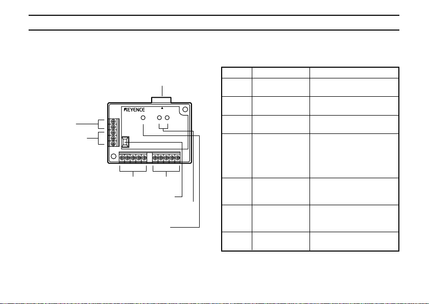
PART NAMES
The following parts identification is common for
both the N-42 and N-48.
2 TRIGGER input
terminals
3 OK/NG output
terminals
4
1 READER port
READER
POWER SD RD
4
Power supply/interface
terminal block
5 Terminator switch
6 Communication status
indicator LEDs
7 POWER LED
No. Name Function
1 READER port Connects to a BL series
or RS-232C equipment.
2 TRIGGER Connect to a sensor for
input terminals trigger input.
3 OK/NG output Output OK/NG signals.
terminals
4 Power supply/ The 24 VDC power supply
interface terminal and
terminal block communication interface
(RS-422A or RS-485)
terminal are provided.
5 Terminator Turns ON/OFF the
switch terminator (termination
resistor: 100Ω).
6 Communication Indicates the RS-422A or
status indicator RS-485 communication
LED status.
7 POWER LED Lights when the power
is turned ON.
Page 5
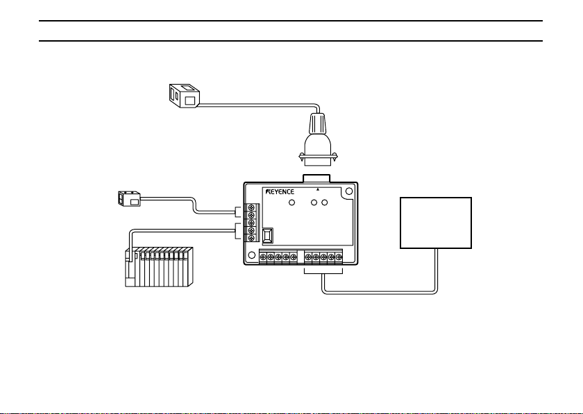
SYSTEM CONFIGURATION
■ N-42
BL series or RS-232C equipment
READER port
Sensor for trigger input
PLC
Trigger
input
OK/NG
output
N-42
POWER SD RD
N-42
READER
Maximum extension distance: 1.2 km
RS-422A
equipment
RS-422A
• When the N-42 is used as an RS-232C/RS-422A converter, connect the RS-232C equipment to the
READER port of the N-42.
• Turn ON the terminator of both the N-42 and the RS-422A equipment (termination resistor: 100 Ω).
5
Page 6
SYSTEM CONFIGURATION
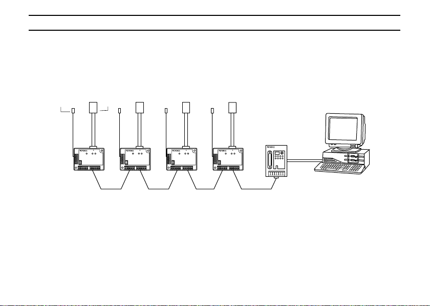
■ N-48
The following diagram shows the system configuration that uses the N-400 multi-drop unit as the
master unit and drives the BL series bar code readers in multi-drop link mode. For details of the multidrop link, see the N-400 User’s Manual.
Sensor for
trigger input
BL series
• Maximum number of
connectable units: 31
• Maximum total extension
distance: 1.2 km
N-400
RS-232C
N-48
*
*
RS-485
Host
• Only the BL-500/180 series enables the multi-drop link connection through the N-400 as shown
above.
• Turn ON the terminator of the equipment marked with an * in the above diagram (termination
resistor: 100 Ω) .
6
Page 7

CONNECTING THE PO WER SUPPLY
24V DC OUT
24V DC IN
RS-485
24 VDC
++
+
––
SG + –
■ N-42
N.C. N.C. N.C.
24V DC IN
++–
24 VDC
■ N-48
Connect a 24 VDC power supply to the 24 V DC IN terminal.
Since the 24 V DC IN and 24 V DC OUT terminals are connected internally, the 24 V DC OUT terminal
can be used as a 24 VDC power output terminal.
CAUTION
• Make sure that a 24 VDC power supply is connected. Using any other power supply may damage
the unit.
• Do not connect power supplies with different voltages to the 24 V DC IN and 24 V DC OUT
terminals. The potential difference between both power supplies may cause abnormal operation.
If your system must meet the UL standards, use a “NEC CLASS 2” power supply for supplying 24
VDC power to these units.
7
Page 8

INPUT/OUTPUT CONNECTIONS
The following I/O connections are common for
both the N-42 and N-48.
■ Connecting trigger input
The trigger input allows the BL series to start
reading bar codes. The trigger input turns ON
when 15 to 26 VDC input is activated.
Contact or
solid-state
15 to 26 VDC
8
TIM
COM
■ Connecting OK/NG output
The BL series uses OK/NG output to compare
the read data with the preset data, or to judge
whether a bar code can be correctly read.
OK
Load
NG
Load
Internal circuit
* Rated load: 30 VDC (100 mA)
* The above circuit diagram shows OK output
COM
only. NG output is provided in the same way.
Internal circuit
Page 9
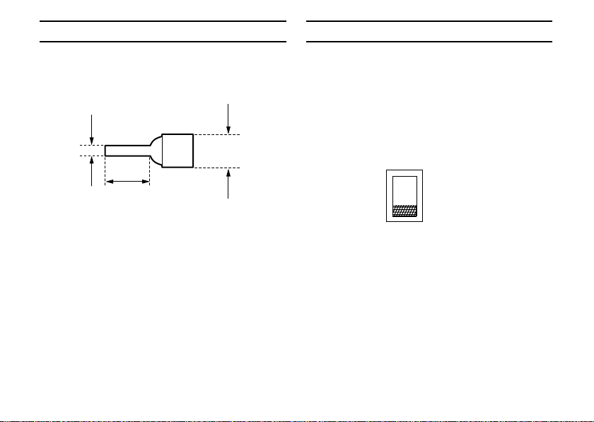
CLIPS USED FOR TERMINALS
To connect the power supply, trigger input and
OK/NG output, you can use the wire-pin clips, as
shown below.
TERMINATOR SWITCH
To connect the N-42/N-48 to RS-422A/RS-485
equipment, turn ON the terminator of the
equipment at both ends of the connection
[marked with * in the system configuration
diagram on p. 6] (termination resistor: 100Ω).
2.0 mm
max.
6 mm min
5 mm max.
<Recommended terminal>
Manufacturer: Japan Solderless Terminal
Mfg.Co.
Model: VTUB-1.25
* The terminator switch is factory-set to OFF.
ON
OFF
9
Page 10

CONNECTING THE BL SERIES
Connect the BL series to the READER port of
the N-42/N-48.
BL Series
READER
POWER SD RD
N-42,N-48
N-42
10
READER port pin assignment
1234
D-sub 9-pin (male)
5
DCE specification (defined as
terminal)
6789
Pin Code Description Signal
No. direction
1 TIM Trigger Output
2 RD (RXD) Send Data Output
3 SD (TXD) Receive Data Input
4 OK OK Input
5 GND (SG) Ground (common to
6 NG NG Input
7 RS (RTS) Request to send Input
8 CS (CTS) Clear to send Output
9 +5 V +5 V power supply Output
#4-40 screw
each signal)
—
Page 11

CONNECTING THE COMMUNICATION INTERFACE
■ N-42
Connect the N-42 to external equipment through
the RS-422A communication interface as
described below.
RS-422A
SG SD+ SD– RD+ RD–
Code Description Signal
SG Ground –
SD+ Sends data to + terminal. Output
SD- Sends data to - terminal. Output
RD+ Receives data from + terminal. Input
RD- Receives data from - terminal. Input
* Turn ON the terminator of both the N-42 and
the external equipment (termination resistor:
100 Ω). (See p. 9.)
* The cable extension distance must be within
1.2 km.
direction
• Connecting N-42 to general RS-422
equipment
To connect the N-42 to another N-42 unit,
perform the same connections.
N-42
SG
SD+
SD–
RD+
RD–
Twisted pair cable
External equipment
(N-42)
SG
RD+
RD–
SD+
SD–
11
Page 12

CONNECTING THE COMMUNICATION INTERFACE
• Connecting N-42 to KV-L2
Twisted pair cable
N-42 KV-L2
SG
SD+
SD–
RD+
RD–
KV-L2 is not available in Europe.
12
SG
RDB
RDA
SDB
SDA
• Connecting N-42 to MELSEC-A series
computer link unit (manufactured by
MITSUBISHI)
Twisted pair cable
N-42
SG
SD+
SD–
RD+
RD–
Link unit
SG
RDA
RDB
SDA
SDB
FG
Page 13

CONNECTING THE COMMUNICATION INTERFACE
■ N-48
To connect the BL series in RS-485 multi-drop
link mode through the N-48, the N-400 multi-drop
unit must be used as the master unit.
For the multi-drop link connecting and operating
procedures, see the N-400 User’s Manual.
The pin assignments for the N-48 and RS-485
equipment are as follows.
Code Description Signal direction
SG Ground –
RS-485+ Sends/receives data to/ Input/Output
RS-485– Sends/receives data to/ Input/Output
from + terminal.
from - terminal.
24V DC OUT
SG SG++––
++––
24V DC IN
RS-485ARS-485
* Up to thirty-one N-48 (BL series) units can be
connected in multi-drop link mode.
* The RS-485 cable’s total extension distance
must be within 1.2 km.
* Turn ON the terminator of the equipment at
both ends of the RS-485 connection (termination resister: 100 Ω) .
13
Page 14

USING N-42 AS RS-232C/RS-422A CONVERTER
The N-42 can be used as a general RS-232C/
RS-422A converter.
For the RS-422A connection, see p. 11 to p.12.
To connect the RS-232C equipment to the
READER port, follow the connection diagram
shown below.
(For pin assignment, see p. 10.)
• Connecting N-42 to PC (with 25-pin
connector)
Connector case
RD
SD
SG
RS
CS
D-sub 9-pin (female)
#4-40 screw
N-42
2
3
5
7
8
PC
FG
1
2
SD
3
RD
7
SG
RS
4
5
CS
DR
6
ER
20
D-sub 25-pin (male)
M2.6 screw
14
• Connecting N-42 to PC (with 9-pin connec-
tor)
Connector
N-42
case
2
RD
3
SD
5
SG
RS
7
CS
8
D-sub 9-pin (female)
#4-40 screw
Connector
case
2PCRD
3
SD
5
SG
RS
7
8
CS
ER
4
DR
6
D-sub 9-pin (female)
#4-40 screw
Page 15

USING N-42 AS RS-232C/RS-422A CONVERTER
CAUTION
• Connecting N-42 to BL-3300 series
Connector
N-42
case
RD
SD
SG
RS
CS
D-sub 9-pin (female)
#4-40 screw
2
3
5
7
8
BL-3300
D-sub 9-pin (female)
#4-40 screw
To connect to the BL-3300 series, use our
optional cable OP-27937 (2 m).
Connector
case
2
SD
3
RD
5
SG
RS
7
CS
8
The READER port pin No. 9 is used for a +5 V
power supply output. Be sure not to use pin No.
9 to connect external equipment. This may
damage the unit.
15
Page 16
INSTALLATION
■ Operating environment
Since the N-42/N-48 is a precision instrument,
choose its operating environment carefully. Avoid
mounting the unit in a location where:
• The ambient temperature may go below 0°C
or above 50°C;
• The relative humidity may go below 35% or
above 85%, or condensation may occur due
to rapid temperature changes;
• A corrosive or inflammable gas is present, or
a high level of dust, salt, iron contents or soot
is present;
• The unit is subject to vibration or impact;
• Water, oil or chemical may splash the unit;
• A strong magnetic field or electric field is
generated.
16
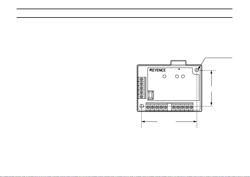
■ Mounting N-42/N-48
To mount the N-42/N-48, use the mounting holes
provided on the unit. The same mounting method
is used for both the N-42 and N-48.
2-ø4.5 mm
mounting hole
READER
POWER SD RD
43.2 mm
N-42
63.2 mm
Page 17
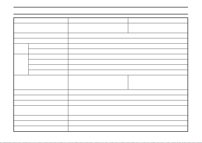
SPECIFICATIONS
Model N-42 N-48
Conversion interface RS-232C ↔ RS-422A RS-232C ↔ RS-485
Connectable bar code reader BL-500 series/BL-180 series
Power supply for bar code reader 5 VDC ±5% (600 mA)
Trigger
input
OK/NG
output
Interface RS-422A
Ambient temperature 0 to 50°C
Relative humidity 35 to 85%
Atmosphere No dust, no corrosive gas
Vibration resistance 10 to 55 Hz, 1.5 mm double amplitude in X, Y and
Power supply voltage 24 VDC +10%/-20%
Current consumption 260 mA max.
Weight Approx. 100 g
Input rating 15 to 26 VDC, 10 mA max.
Max. OFF current 1.0 mA
Output type NPN open-collector
Rated load 30 VDC, 100 mA
Leak current (at OFF) 0.1 mA max.
Residual voltage (at ON) 1 V max.
(level conversion) (level conversion)
(Maximum extension
distance: 1.2 km)
Z directions, two hours respectively
RS-485 (Maximum number of
connectable units: 31, Maximum
total extension distance: 1.2 km)
17
Page 18
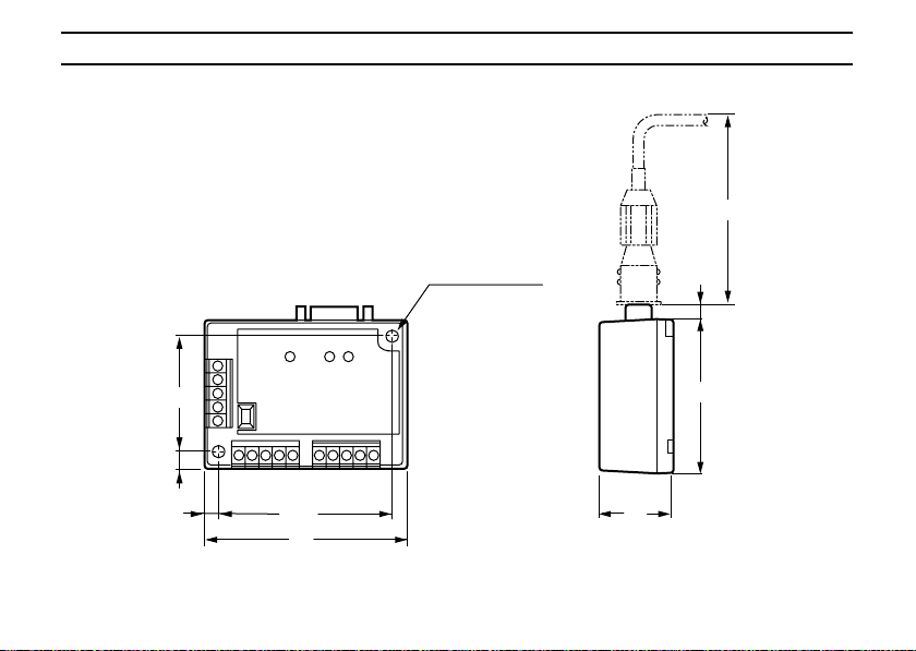
DIMENSIONS
Unit: mm
(70)
18
43.2
5.9
5.9
63.2
75
2 x ø4.5
mounting hole
5.5
55
26
Page 19

19
Page 20

Specifications are subject to change without notice.
KEYENCE CORPORATION OF AMERICA
PHONE: 201-930-0100 FAX: 201-930-0099
Worldwide Headquarters
KEYENCE CORPORATION
1-3-14, Higashi-Nakajima,
Higashi-Yodogawa-ku,
Osaka, 533-8555, Japan
PHONE: 81-6-6379-2211
FAX: 81-6-6379-2131
KEYENCE (UK) LIMITED
PHONE: 01908-696900 FAX: 01908-696777
KEYENCE DEUTSCHLAND GmbH
PHONE: 0711-797371-0 FAX: 0711-7977799
KEYENCE FRANCE S.A.
PHONE: 01 47 92 76 76 FAX: 01 47 92 76 77
KEYENCE SINGAPORE PTE LTD
PHONE: 392-1011 FAX: 392-5055
KEYENCE (MALAYSIA) SDN BHD
PHONE: 03-252-2211 FAX: 03-252-2131
KEYENCE (THAILAND) CO., LTD
PHONE: 02-934-6777 FAX: 02-934-6775
KEYENCE KOREA CORPORATION
PHONE: 02-563-1270 FAX: 02-563-1271
POP-BLU2-I1-1-2321
 Loading...