

Page 1
96M11027
Read this manual before using the system in order to
achieve maximum performance.
Keep this manual in a safe place for future reference.
RS-485 Master Unit
User's Manual
N-410
Page 2

Introduction
Thank you for purchasing the N-410 RS-485 master unit.
The N-410 can be used as a master unit on a multi-drop link network of KEYENCE BL Series
barcode readers, SR Series code readers, and RF Series RFID system.
This manual explains the connections, communications and additional functions for using the
N-410 on a multi-drop link network with BL/SR/RF Series devices.
Please read this manual carefully.
The devices that can be connected to the N-410 are the BL-700 Series, the BL-600 Series, the BL180 Series, the BL-210 Series, the RF-500 Series, the SR-500 Series, the BL-1300 Series, and the SR600 Series.
Manuals related to the N-410
Be sure to read the following manuals when using the N-410.
Manual Contents
BL-700 Series
BL-U1, BL-U2, N-42
User’s Manual
BL-600 Series
User’s Manual
BL-180 Series
User’s Manual
BL-210 Series
User’s Manual
RF-500
Installation and
Connection Manual
RF-500
Operation Manual
AutoID Navigator
User’s Manual
(PDF only)
N-410
User’s Manual
SR-500 Series
User’s Manual
BL-1300 Series
User’s Manual
SR-600 Series
User’s Manual
This explains the connections, wiring, installation, settings and notes for the BL700 Series long-range laser barcode reader and the BL-U1, BL-U2 and N-42
communication units.
This explains the connections, wiring, installation, settings and notes for the BL600 Series ultra-short range laser barcode reader.
This explains the connections, wiring, installation, settings and notes for the BL180 Series ultra-short range CCD barcode reader.
This explains the connections, wiring, installation, settings and notes for the BL210 Series handy laser barcode reader.
This manual explains the connections, installation and operation of the RF-500
Series and related devices.
This section explains the operation of the devices that make up the system, the
settings for operation
the communication commands for those devices.
and
This explains the indicates operation and settings for the AutoID Navigator
general AutoID system setting software.
This manual.
This explains the settings and procedures required for installation, connection
and operation of the N-410 RF-485 master unit.
This explains the connections, wiring, installation, settings and notes for the SR500 Series fixed 2D code reader.
This explains the connections, wiring, installation, settings and notes for the BL1300 Series laser barcode reader.
This explains the connections, wiring, installation, settings and notes for the SR600 Series fixed 2D code reader.
Page 3
Safety Precautions
Important
Note
Reference
This manual explains the usage, procedure and cautions of the N-410.
To get the most out of your N-410, make sure that you have read and understood this manual.
Always keep this manual in a safe place for future reference whenever needed.
Ensure that the manual is passed to the end user in case of transfer of the unit.
Symbols
The following warning symbols are used to ensure safety and to prevent injury and/or damage to
property when using the N-410.
Danger
Warning
Caution
Indicates that the operator is at risk of death or serious physical injury if the
system is improperly operated or this precaution is not followed.
Indicates that the operator is at risk of physical injury if the system is
improperly operated or this precaution is not followed.
Indicates that property damage (including product malfunction) may occur if
the system is improperly operated or if this precaution is not followed.
Indicates cautions and controls that must be observed while using this device.
Indicates an important operating procedure that could be easily overlooked.
Indicates further information that may be useful to know.
Indicates a page in this manual or another manual to refer to.
96M11027
1
Page 4
General Cautions
• Before starting work or before starting the system, confirm that all the functions of the system are
working properly.
• If any product of our company fails, take full safety measures to prevent damage before using the
system again.
• If the system is used beyond published specifications or if the system is modified, the functions
and performance cannot be guaranteed.
• Please note that when the N-410 is used in combination with other instruments, its functions and
performance may be degraded,
• Do not use the N-410 for protecting the human body.
Be Sure to Use this Product Correctly
Caution
• Refer to "2-8 Installation" (Page 2-32) before installing and make sure to install the device in an
appropriate place.
• Use the recommended cables for RS-485 connections and make sure those connections are made as
specified in this manual.
• If the wiring is not handled as specified, communication errors may occur.
"Wiring an RS-485" (Page 2-24)
"Wiring an RS-485" (Page 2-30)
• Be sure to use only 24 V DC power for the N-410, N-R4, N-48, NX-50RS.
Use of any other power source may result in damage
• This is a precision instrument. It may be damaged if dropped. Take care
when carrying or installing this device.
2
Page 5

UL/CE Certification
Notes regarding the international certifications of the N-410
Europe
Notes regarding EMC directives (2004/108/EC)
Keyence Corporation has confirmed that this product complies with the essential
requirements of the applicable EU Directives, based on the following specifications.
Be sure to consider the following specifications when using this product in the
Member States of European Union.
• General certification (EMI) EN61326-1 Class A
• General certification (EMS) EN61326-1
• I/O cables and power cables should be shorter than 30 m.
These specifications do not give any guarantee that the end-product with this product incorporated
complies with the essential requirements of EMC Directive. The manufacturer of the end-product is solely
responsible for the compliance on the end-product itself according to EMC Directive.
America
Notes regarding the FCC
The N-410 is regulated by the FCC.
• General certification FCC Part 15 Subpart B - Unintentional Radiator,
Class A digital device
Notes regarding UL certification
The N-410 is regulated by the UL/CSA and bears UL/C-UL certification.
• Certifications UL508
CAN/CSA C22.2 No. 14-M95
• UL File No. E207185
• UL categories NRAQ, NRAQ7
• Be sure to use an NFPA70 (NEC: National Electrical Code) certified Class 2 electrical output.
• Place this on the control board.
Canada
Notes regarding Canada IC (Industry Canada) regulation
The N-410 is regulated by Canadian Electromagnetic Wave Regulations.
• General regulation ICES-003 - Digital Apparatus, Class A
3
Page 6
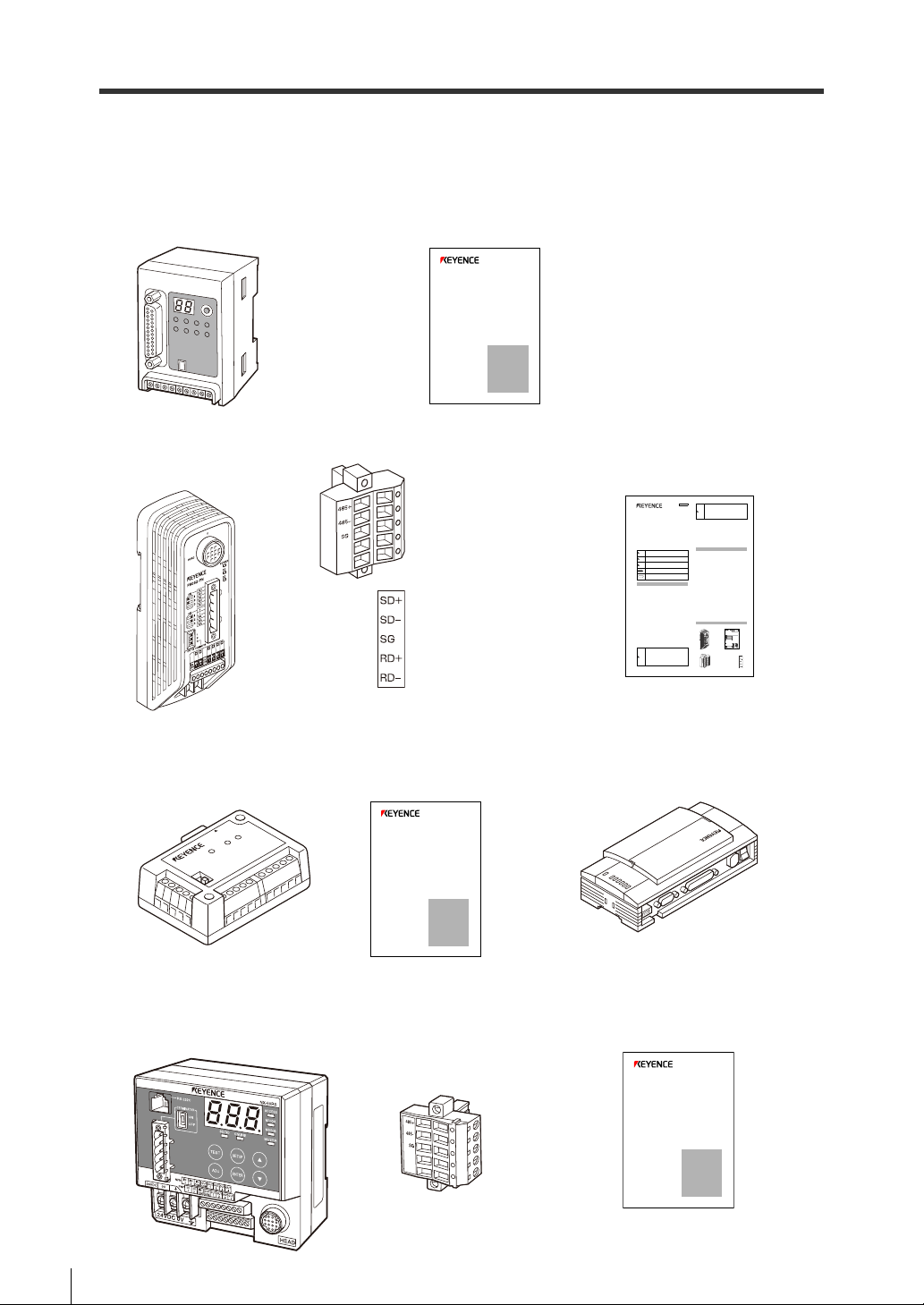
Package Contents
N-410...1
User's manual...1
User's Manual
1
E N-R4-IM
Dedicated Communication Unit
RS-422A/485 Output Type
N-R4
Instruction Manual
■General precautions
• At startup and during operation, be sure to check that the
functions and performance of the N-R4 is operating properly.
• We recommend that you take substantial safety measures to
avoid any damage in the event a problem occurs.
• If the N-R4 is modified or used in any way other than described in
the specifications, its function and performance cannot be
guaranteed.
• When the N-R4 is used in combination with other instruments, the
function and performance may be effected by operating conditions
and the surrounding environment.
• Do not use the N-R4 for the purpose of protecting the human
body.
• The information contained in this manual is subject to change
without notice.
■Notice
When this product is used under the circumstances and operating
environments described below, adhere to the limitations of the ratings,
take adequate measures to ensure safety such as fail-safe installations
and consult a KEYENCE sales representative.
• For use under circumstances or environments which are not
described in the manual
• For use with nuclear power control, railway, aircraft, vehicles,
incinerators, medical equipment, entertainment equipment, safety
devices etc.
• For use in applications where death or serious property damage is
possible and extensive safety precautions are required.
■For properly using the product
Do not install the N-R4 in the following locations:
• Locations subject to direct sunlight
• Locations where the surrounding air temperature is outside the
range of 0 to +50C or locations subject to condensation as the
result of severe changes in temperature
• Locations where the ambient humidity is outside the range of 35
to 85%RH.
• Locations subject to corrosive or flammable gases
• Locations subject to dust, salts, iron dust, or oil smoke
• Locations subject to shock or vibration
• Locations subject to exposure of water, oil, or chemicals
• Locations where strong magnetic or electric fields are generated
■UL certification
The N-R4 complies with the following UL/CSA standards and has
obtained the UL/C-UL certification.
• Applicable standards UL508, UL60950-1
• UL File No. E207185, E167973
• UL category NRAQ/NRAQ7, NWGQ2/NWGQ8
Be sure to observe the following installation and environment conditions.
• Pollution degree 2
• Overvoltage category I
Caution - Do not connect directly to the branch circuit. This product must
be supplied power by a suitable, approved isolated transformer or power
supply not exceeding 200 VA max.
■FCC regulations
The N-R4 complies with the following FCC EMI regulations.
• FCC Part 15 Subpart B, Class B digital device
■Canada IC (Industry Canada) regulations
The N-R4 complies with the following IC EMI regulations.
• ICES-003, Class B digital apparatus
■CE marking
The N-R4 complies with the following essential requirements of the EU
Directive.
• EMC Directive (2004/108/EC)
The following harmonized standards are applied to this product in order
to confirm the compliance.
• Applicable standards (EMI) EN55011, Class A
EN55022, Class B
• Applicable standards (EMS) EN61000-6-2
EN61000-6-1
*The length of the communication and power cables should be less than 30 m.
DANGER
Failure to follow these instructions may lead to death or
serious injury.
WARNING
Failure to follow these instructions may lead to injury.
CAUTION
Failure to follow these instructions may lead to product
damage (product malfunction, etc.).
Note
Provides additional information on proper operation.
TIPS
Indicates useful information or information that aids
understanding of text descriptions.
For Safely Using the Product
CAUTION
•
Do not use the N-R4 in an environment subject to
flammable, explosive, or corrosive gases.
•Be sure that all screws are tightened securely.
•Use crimp contacts of the specified size for wiring.
•The N-R4 uses a 24 VDC power supply. Using a power
supply outside this range or an AC power supply may
cause product failure.
•
Do not disassemble or modify the N-R4. This may cause
product failure.
96M00269
CAUTION
•Locate the cables as far as possible from high-voltage
lines and power lines. Otherwise, generated noise may
cause product failure or malfunctions.
•The N-R4 is a precision instrument. If the unit is
dropped or shock is applied, it may be damaged. Use
caution when unpacking, carrying, and mounting.
•Be sure to observe all warnings, cautions, and
precautions specified in the manual.
Foreign Regulations and Standards
Package Contents List
1
E N-R4-IM
Dedicated Communication Unit
RS-422A/485 Output Type
N-R4
Instruction Manual
General precautions
•At startup and during operation, be sure to check that the
functions and performance of the N-R4 is operating properly.
•We recommend that you take substantial safety measures to
avoid any damage in the event a problem occurs.
•If the N-R4 is used in any way other than described in the
specifications or if modified, its functions and performance cannot
be guaranteed.
•When the N-R4 is used in combination with other instruments,
functions and performance may be degraded, depending on the
operating conditions and the surrounding environment.
•Do not use the N-R4 for the purpose of protecting the human
body.
•The information contained in this manual is subject to change
without notice.
Notice
When the product is used under the circumstances or environment
below, adhere to the limitations of the ratings and functions, take
countermeasures for safety precautions such as fail-safe installations
and consult a KEYENCE sales representative.
•For use under circumstances or environments which are not
described in the manual
•For use with nuclear power control, railway, aircraft, vehicles,
incinerators, medical equipment, entertainment equipment, safety
devices etc.
•For use for applications where death or serious property damage
is possible and extensive safety precautions are required
For properly using the product
Do not install the N-R4 in the following locations:
•Locations subject to direct sunlight
•Locations where the ambient temperature is outside the range of
0to +50°C or locations subject to condensation as the result of
severe changes in temperature
•Locations where the ambient humidity is outside the range of 35
to 85%RH.
•Locations subject to corrosive or flammable gases
•Locations subject to dust, salts, iron dust, or oil smoke
•Locations subject to shock or vibration
•Locations subject to exposure of water, oil, or chemicals
•Locations where strong magnetic or electric fields are generated
UL approval
The N-R4 conforms to the following UL/CSA standards and has obtained
the UL/C-UL approval.
•Conforming standardsUL508, UL60950-1
•UL File No. E207185, E167973
•UL category NRAQ/NRAQ7, NWGQ2/NWGQ8
When using the N-R4 as a UL approved product, be sure to observe the
following installation and environment conditions.
•Pollution degree 2
•Overvoltage category I
FCC regulations
The N-R4 conforms to the following FCC EMI regulations.
•Conforming regulationsFCC Part 15 Subpart B, Class B
digital equipment
Canada IC (Industry Canada regulations)
The N-R4 conforms to the following IC EMI regulations.
•Conforming regulationsICES-003, Class B Digital equipment
CE marking
The N-R4 conforms to the following essential requirements of the EU
directive.
•EMC directive (2004/108/EC)
By checking the conformity to the following EN standards, the conformity
to the essential requirements of the EMC directive is checked and the CE
marking is indicated.
•Conforming standards (EMI)EN55011, Class A
EN55022, Class B
•Conforming standards (EMS)EN61000-6-2
EN61000-6-1
*The length of the communication and power cables should be less than 30 m.
DANGER
Failure to follow these instructions may lead to death or
serious injury.
WARNING
Failure to follow these instructions may lead to injury.
CAUTION
Failure to follow these instructions may lead to product
damage (product malfunction, etc.).
Note
Provides additional information on proper operation.
TIPS
Indicates useful information or information that aids
understanding of text descriptions.
For Safely Using the Product
CAUTION
•
Do not use the N-R4 in an environment subject to
flammable, explosive, or corrosive gases.
•Be sure that all screws are tightened securely.
•Use crimp contacts of the specified size for wiring.
•The N-R4 uses a 24 VDC power supply. Using a power
supply outside this range or an AC power supply may
cause product failure.
•
Do not disassemble or modify the N-R4. This may cause
product failure.
96M00275
CAUTION
•Locate the cables as far as possible from high-voltage
lines and power lines. Otherwise, generated noise may
cause product failure or malfunctions.
•The N-R4 is a precision instrument. If the unit is
dropped or shock is applied, it may be damaged. Use
caution when unpacking, carrying, and mounting.
•Be sure to observe all warnings, cautions, and
precautions specified in the manual.
Foreign Regulations and Standards
Package Contents List
Main unit Instruction manual
Connector for the RS-422A/485Seal for the connectors
(used when wiring RS-422A)
For 422 connector
1
E N-R4-IM
Dedicated Communication Unit
RS-422A/485 Output Type
N-R4
Instruction Manual
General precautions
•At startup and during operation, be sure to check that the
functions and performance of the N-R4 is operating properly.
•We recommend that you take substantial safety measures to
avoid any damage in the event a problem occurs.
•If the N-R4 is used in any way other than described in the
specifications or if modified, its functions and performance cannot
be guaranteed.
•When the N-R4 is used in combination with other instruments,
functions and performance may be degraded, depending on the
operating conditions and the surrounding environment.
•Do not use the N-R4 for the purpose of protecting the human
body.
•The information contained in this manual is subject to change
without notice.
Notice
When the product is used under the circumstances or environment
below, adhere to the limitations of the ratings and functions, take
countermeasures for safety precautions such as fail-safe installations
and consult a KEYENCE sales representative.
•For use under circumstances or environments which are not
described in the manual
•For use with nuclear power control, railway, aircraft, vehicles,
incinerators, medical equipment, entertainment equipment, safety
devices etc.
•For use for applications where death or serious property damage
is possible and extensive safety precautions are required
For properly using the product
Do not install the N-R4 in the following locations:
•Locations subject to direct sunlight
•Locations where the ambient temperature is outside the range of
0to +50°C or locations subject to condensation as the result of
severe changes in temperature
•Locations where the ambient humidity is outside the range of 35
to 85%RH.
•Locations subject to corrosive or flammable gases
•Locations subject to dust, salts, iron dust, or oil smoke
•Locations subject to shock or vibration
•Locations subject to exposure of water, oil, or chemicals
•Locations where strong magnetic or electric fields are generated
UL approval
The N-R4 conforms to the following UL/CSA standards and has obtained
the UL/C-UL approval.
•Conforming standardsUL508, UL60950-1
•UL File No.E207185, E167973
•UL categoryNRAQ/NRAQ7, NWGQ2/NWGQ8
When using the N-R4 as a UL approved product, be sure to observe the
following installation and environment conditions.
•Pollution degree 2
•Overvoltage category I
FCC regulations
The N-R4 conforms to the following FCC EMI regulations.
•Conforming regulationsFCC Part 15 Subpart B, Class B
digital equipment
Canada IC (Industry Canada regulations)
The N-R4 conforms to the following IC EMI regulations.
•Conforming regulationsICES-003, Class B Digital equipment
CE marking
The N-R4 conforms to the following essential requirements of the EU
directive.
•EMC directive (2004/108/EC)
By checking the conformity to the following EN standards, the conformity
to the essential requirements of the EMC directive is checked and the CE
marking is indicated.
•Conforming standards (EMI)EN55011, Class A
EN55022, Class B
•Conforming standards (EMS)EN61000-6-2
EN61000-6-1
*The length of the communication and power cables should be less than 30 m.
DANGER
Failure to follow these instructions may lead to death or
serious injury.
WARNING
Failure to follow these instructions may lead to injury.
CAUTION
Failure to follow these instructions may lead to product
damage (product malfunction, etc.).
Note
Provides additional information on proper operation.
TIPS
Indicates useful information or information that aids
understanding of text descriptions.
For Safely Using the Product
CAUTION
•
Do not use the N-R4 in an environment subject to
flammable, explosive, or corrosive gases.
•Be sure that all screws are tightened securely.
•Use crimp contacts of the specified size for wiring.
•The N-R4 uses a 24 VDC power supply. Using a power
supply outside this range or an AC power supply may
cause product failure.
•
Do not disassemble or modify the N-R4. This may cause
product failure.
96M00275
CAUTION
•Locate the cables as far as possible from high-voltage
lines and power lines. Otherwise, generated noise may
cause product failure or malfunctions.
•The N-R4 is a precision instrument. If the unit is
dropped or shock is applied, it may be damaged. Use
caution when unpacking, carrying, and mounting.
•Be sure to observe all warnings, cautions, and
precautions specified in the manual.
Foreign Regulations and Standards
Package Contents List
Main unitInstruction manual
1
EN-R2-IM
Dedicated Communication Unit
RS-232C Output Type
N-R2
Instruction Manual
General precautions
•At startup and during operation, be sure to check that the
functions and performance of the N-L1 is operating properly.
•We recommend that you take substantial safety measures to
avoid any damage in the event a problem occurs.
•If the N-L1 is used in any way other than described in the
specifications or if modified, its functions and performance cannot
be guaranteed.
•When the N-L1 is used in combination with other instruments,
functions and performance may be degraded, depending on the
operating conditions and the surrounding environment.
•Do not use the N-L1 for the purpose of protecting the human body.
•The information contained in this manual is subject to change
without notice.
Notice
When the product is used under the circumstances or environment
below, adhere to the limitations of the ratings and functions, take
countermeasures for safety precautions such as fail-safe installations
and consult a KEYENCE sales representative.
•For useunder circumstances or environmentswhich are not
described in the manual
•For usewith nuclear power control, railway, aircraft, vehicles,
incinerators, medical equipment, entertainment equipment, safety
devices etc.
•For use for applications where death or serious property damage
is possible and extensive safety precautions are required
For properly using the product
Do not install the N-R2 in the following locations:
•Locations subject to direct sunlight
•Locations where the ambient temperature is outside the range of
0to +50°C or locations subject to condensation as the result of
severe changes in temperature
•Locations where the ambient humidity is outside the range of 35
to85%RH.
•Locations subject to corrosive or flammable gases
•Locations subject to dust, salts, iron dust, or oil smoke
•Locations subject to shock or vibration
•Locations subject to exposure of water, oil, or chemicals
•Locations where strong magnetic or electric fields are generated
UL approval
The N-R2 conforms to the following UL/CSA standards and has obtained
the UL/C-UL approval.
•Conforming standardsUL508, UL60950-1
•UL File No.E207185, E167973
•UL categoryNRAQ/NRAQ7, NWGQ2/NWGQ8
When using the N-R2 as a UL approved product,be sure to observe the
following installation and environment conditions.
•Pollution degree 2
•Overvoltage category I
FCC regulations
The N-R2 conforms to the following FCC EMI regulations.
•Conforming regulationsFCC Part 15 Subpart B, Class B
digital equipment
Canada IC (Industry Canada regulations)
TheN-R2 conforms to the following IC EMI regulations.
•Conforming regulationsICES-003, Class B Digital equipment
CE marking
The N-R2 conforms to the following essential requirements of the EU
directive.
•EMC directive (2004/108/EC)
By checking the conformity to the following EN standards, the conformity
to the essential requirements of the EMC directive is checked and the CE
marking is indicated.
•Conforming standards (EMI)EN55011, Class A
EN55022, Class B
•Conforming standards (EMS)EN61000-6-2
EN61000-6-1
*The length of the communication and power cables should be less than 30 m.
DANGER
Failure to follow these instructions may lead to death or
serious injury.
WARNING
Failure to follow these instructions may lead to injury.
CAUTION
Failure to follow these instructions may lead to product
damage (product malfunction, etc.).
Note
Provides additional information on proper operation.
TIPS
Indicates useful information or information that aids
understanding of text descriptions.
For Safely Using the Product
CAUTION
•Do not use the N-L1 in an environment subject to
flammable, explosive, or corrosive gases.
•Be sure that all screws are tightened securely.
•Use crimp contacts of the specified size for wiring.
•The N-L1 uses a 24 VDC power supply. Using a power
supply outside this range or an AC power supply may
cause product failure.
•Do not disassemble or modify the N-L1. This may cause
product failure.
96M00266
CAUTION
•Locate the cables as far as possible from high-voltage
lines and power lines. Otherwise, generated noise may
cause product failure or malfunctions.
•The N-R2 is a precision instrument. If the unit is
dropped or shock is applied, it may be damaged. Use
caution when unpacking, carrying, and mounting.
•Be sure to observe all warnings, cautions, and
precautions specified in the manual.
Foreign Regulations and Standards
Package Contents List
Main unitInstruction manual
1
EN-R2-IM
Dedicated Communication Unit
RS-232C Output Type
N-R2
Instruction Manual
General precautions
•At startup and during operation, be sure to check that the
functions and performance of the N-L1 is operating properly.
•We recommend that you take substantial safety measures to
avoid any damage in the event a problem occurs.
•If the N-L1 is used in any way other than described in the
specifications or if modified, its functions and performance cannot
be guaranteed.
•When the N-L1 is used in combinationwith other instruments,
functions and performance may be degraded, depending on the
operating conditions and the surrounding environment.
•Do not use the N-L1 for the purpose of protecting the human body.
•The information contained in this manual is subject to change
without notice.
Notice
When the product is usedunder the circumstances or environment
below, adhere to the limitations of the ratings and functions, take
countermeasures for safety precautions such as fail-safe installations
and consult a KEYENCE sales representative.
•For useunder circumstances or environments which are not
described in the manual
•For usewith nuclear power control, railway, aircraft, vehicles,
incinerators, medical equipment, entertainment equipment, safety
devices etc.
•For use for applications where death or serious property damage
is possible and extensive safety precautions are required
For properly using the product
Do not install the N-R2 in the following locations:
•Locations subject to direct sunlight
•Locations where the ambient temperature is outside the range of
0to +50°C or locations subject to condensation as the result of
severe changes in temperature
•Locations where the ambient humidity is outside the range of 35
to85%RH.
•Locations subject to corrosive or flammable gases
•Locations subject to dust, salts, iron dust, or oil smoke
•Locations subject to shock or vibration
•Locations subject to exposure of water, oil, or chemicals
•Locations where strong magnetic or electric fields are generated
UL approval
TheN-R2 conforms to the following UL/CSA standards and has obtained
the UL/C-UL approval.
•Conforming standardsUL508, UL60950-1
•UL File No.E207185, E167973
•UL categoryNRAQ/NRAQ7, NWGQ2/NWGQ8
Whenusing the N-R2 as a UL approved product,be sure to observe the
following installation and environment conditions.
•Pollution degree 2
•
Overvoltage category I
FCC regulations
TheN-R2 conforms to the following FCC EMI regulations.
•Conforming regulationsFCC Part 15 Subpart B, Class B
digital equipment
Canada IC (Industry Canada regulations)
TheN-R2 conforms to the following IC EMI regulations.
•Conforming regulationsICES-003, Class B Digital equipment
CE marking
TheN-R2 conforms to the following essential requirements of the EU
directive.
•EMC directive (2004/108/EC)
By checking the conformity to the following EN standards, the conformity
to the essential requirements of the EMC directive is checked and the CE
marking is indicated.
•Conforming standards (EMI)EN55011, Class A
EN55022, Class B
•Conforming standards (EMS)EN61000-6-2
EN61000-6-1
*The length of the communication and power cables should be less than 30 m.
DANGERFailure to follow these instructions may lead to death or
serious injury.
WARNINGFailure to follow these instructions may lead to injury.
CAUTION
Failure to follow these instructions may lead to product
damage (product malfunction, etc.).
Note
Provides additional information on proper operation.
TIPS
Indicates useful information or information that aids
understanding of text descriptions.
For Safely Using the Product
CAUTION
•Do not use the N-L1 in an environment subject to
flammable, explosive, or corrosive gases.
•Be sure that all screws are tightened securely.
•Use crimp contacts of the specified size for wiring.
•The N-L1 uses a 24 VDC power supply. Using a power
supply outside this range or an AC power supply may
cause product failure.
•Do not disassemble or modify the N-L1. This may cause
product failure.
96M00266
CAUTION
•Locate the cables as far as possible from high-voltage
lines and power lines. Otherwise, generated noise may
cause product failure or malfunctions.
•The N-R2 is a precision instrument. If the unit is
dropped or shock is applied, it may be damaged. Use
caution when unpacking, carrying, and mounting.
•Be sure to observe all warnings, cautions, and
precautions specified in the manual.
Foreign Regulations and Standards
Package Contents List
MainunitInstruction manual
Connector for the RS-422A/485Seal for the connectors
(used when wiring RS-422A)
For 422 connector
Main unit Instruction manual
Connector for the RS-422A/485 Label for the connectors
(used when wiring RS-422A)
For 422 connector
N-R4...1 Instruction manual...1Connector for
RS-422A/485...1
RS-422A
Terminal layout label...1
BL-U1...1N-48...1 Instruction manual...1
NX-50RS...1 RS-485
connector...1
Instruction manual...1
The following parts and devices can be found in this package. Confirm that all parts are present and
accounted for before using the device.
N-410 package contents
N-R4 package contents
N-48 package contents BL-U1 package contents
NX-50RS package contents
4
Instruction Maual
Instruction Maual
Page 7
Organization of this Manual
1234567
Chapter
1
Chapter
2
Chapter
3
Chapter
4
Chapter
5
Chapter
6
N-410 Overview
Installation
N-410 Settings
Controlling Multi-
drop Link Mode
Controlling Multi-
head Mode
Serial
Communication
This chapter outlines the features and functions of the N-410, as well as
the part names and the required system architecture.
This chapter describes how to connect the N-410 and confirm the
connection.
The AutoID Navigator is used to make settings for the N-410. This
chapter describes how to make the settings for the N-410.
This chapter describes how to control multi-drop link mode for the N-410.
This chapter describes how to control multi-head mode for the N-410.
This chapter describes the serial commands and configuration
commands for the N-410 Series
Chapter
7
PLC Link
Appendices
This chapter describes how to set and control the N-410 PLC link.
The chapter describes the exterior dimensions of the N-410, factory
default settings, error codes and other specifications.
5
Page 8

Table of Contents
Safety Precautions . . . . . . . . . . . . . . . . . . . . . . . . . . . . . . . . . . . . . . . . . . . . . . . . . . . . . . . . 1
Be Sure to Use this Product Correctly. . . . . . . . . . . . . . . . . . . . . . . . . . . . . . . . . . . . . . . . . . 2
UL/CE Certification . . . . . . . . . . . . . . . . . . . . . . . . . . . . . . . . . . . . . . . . . . . . . . . . . . . . . . . . 3
Package Contents . . . . . . . . . . . . . . . . . . . . . . . . . . . . . . . . . . . . . . . . . . . . . . . . . . . . . . . . . 4
Organization of this Manual . . . . . . . . . . . . . . . . . . . . . . . . . . . . . . . . . . . . . . . . . . . . . . . . . 5
Table of Contents . . . . . . . . . . . . . . . . . . . . . . . . . . . . . . . . . . . . . . . . . . . . . . . . . . . . . . . . . 6
How to Read this Manual . . . . . . . . . . . . . . . . . . . . . . . . . . . . . . . . . . . . . . . . . . . . . . . . . . . 9
Page Layout . . . . . . . . . . . . . . . . . . . . . . . . . . . . . . . . . . . . . . . . . . . . . . . . . . . . . . . . . . . . . 9
Terms. . . . . . . . . . . . . . . . . . . . . . . . . . . . . . . . . . . . . . . . . . . . . . . . . . . . . . . . . . . . . . . . . . 10
Symbols. . . . . . . . . . . . . . . . . . . . . . . . . . . . . . . . . . . . . . . . . . . . . . . . . . . . . . . . . . . . . . . . 10
Chapter 1 N-410 Overview
1-1 What You Can Do with the N-410 . . . . . . . . . . . . . . . . . . . . . . . . . . . . . . . . . . . . . 1-2
1-2 System Configuration . . . . . . . . . . . . . . . . . . . . . . . . . . . . . . . . . . . . . . . . . . . . . . 1-4
1-3 Part Names . . . . . . . . . . . . . . . . . . . . . . . . . . . . . . . . . . . . . . . . . . . . . . . . . . . . . . . 1-5
Chapter 2 Installation
2-1 Making Settings and Connections . . . . . . . . . . . . . . . . . . . . . . . . . . . . . . . . . . . . 2-2
2-2 N-410 Connections and Wiring. . . . . . . . . . . . . . . . . . . . . . . . . . . . . . . . . . . . . . . 2-5
Installing and Wiring the Input and Output Jacks . . . . . . . . . . . . . . . . . . . . . . . . . . . . . . . .2-5
RS-232C Connections . . . . . . . . . . . . . . . . . . . . . . . . . . . . . . . . . . . . . . . . . . . . . . . . . . . . .2-7
2-3 Connecting and Wiring to the N-R4 Series . . . . . . . . . . . . . . . . . . . . . . . . . . . . 2-10
Connecting to BL-1300 Series/SR Series/RF Series Devices . . . . . . . . . . . . . . . . . . . . . .2-10
Connecting the Power Supply. . . . . . . . . . . . . . . . . . . . . . . . . . . . . . . . . . . . . . . . . . . . . .2-11
I/O Terminal Layout and Wiring . . . . . . . . . . . . . . . . . . . . . . . . . . . . . . . . . . . . . . . . . . . . .2-12
2-4 NX-50RS Connections and Wiring . . . . . . . . . . . . . . . . . . . . . . . . . . . . . . . . . . . 2-16
2-5 N-48 Connections and Wiring. . . . . . . . . . . . . . . . . . . . . . . . . . . . . . . . . . . . . . . 2-20
Connecting to a BL/SR/RF Series Device . . . . . . . . . . . . . . . . . . . . . . . . . . . . . . . . . . . . .2-20
Installing and Wiring the Input and Output Jacks . . . . . . . . . . . . . . . . . . . . . . . . . . . . . . .2-21
Wiring an RS-485. . . . . . . . . . . . . . . . . . . . . . . . . . . . . . . . . . . . . . . . . . . . . . . . . . . . . . . .2-24
2-6 BL-U1 Connections and Wiring . . . . . . . . . . . . . . . . . . . . . . . . . . . . . . . . . . . . . 2-26
Electrical Wiring. . . . . . . . . . . . . . . . . . . . . . . . . . . . . . . . . . . . . . . . . . . . . . . . . . . . . . . . .2-26
Connecting to a BL/SR/RF Series Device . . . . . . . . . . . . . . . . . . . . . . . . . . . . . . . . . . . . .2-26
BL-U1 Dipswitch Settings . . . . . . . . . . . . . . . . . . . . . . . . . . . . . . . . . . . . . . . . . . . . . . . . .2-27
Installing and Wiring the Input and Output Jacks . . . . . . . . . . . . . . . . . . . . . . . . . . . . . . .2-28
Wiring an RS-485. . . . . . . . . . . . . . . . . . . . . . . . . . . . . . . . . . . . . . . . . . . . . . . . . . . . . . . .2-30
2-7 How to Use the Connection Confirmation Test. . . . . . . . . . . . . . . . . . . . . . . . . 2-31
2-8 Installation . . . . . . . . . . . . . . . . . . . . . . . . . . . . . . . . . . . . . . . . . . . . . . . . . . . . . . 2-32
Installation Notes . . . . . . . . . . . . . . . . . . . . . . . . . . . . . . . . . . . . . . . . . . . . . . . . . . . . . . . .2-32
Installing an N-410 . . . . . . . . . . . . . . . . . . . . . . . . . . . . . . . . . . . . . . . . . . . . . . . . . . . . . .2-33
Installing an NX-50RS . . . . . . . . . . . . . . . . . . . . . . . . . . . . . . . . . . . . . . . . . . . . . . . . . . . .2-34
Installing an N-48 . . . . . . . . . . . . . . . . . . . . . . . . . . . . . . . . . . . . . . . . . . . . . . . . . . . . . . .2-34
Installing a BL-U1 . . . . . . . . . . . . . . . . . . . . . . . . . . . . . . . . . . . . . . . . . . . . . . . . . . . . . . .2-35
Installing the N-R4 . . . . . . . . . . . . . . . . . . . . . . . . . . . . . . . . . . . . . . . . . . . . . . . . . . . . . . .2-36
6
Page 9

Chapter 3 N-410 Settings
3-1 Making Settings . . . . . . . . . . . . . . . . . . . . . . . . . . . . . . . . . . . . . . . . . . . . . . . . . . . 3-2
3-2 Sending and Receiving Settings . . . . . . . . . . . . . . . . . . . . . . . . . . . . . . . . . . . . . 3-9
3-3 Using Terminal and Test Mode . . . . . . . . . . . . . . . . . . . . . . . . . . . . . . . . . . . . . . 3-12
Chapter 4 Controlling Multi-drop Link Mode
4-1 Multi-drop Link Mode. . . . . . . . . . . . . . . . . . . . . . . . . . . . . . . . . . . . . . . . . . . . . . . 4-2
Controlling Multi-drop Link Mode . . . . . . . . . . . . . . . . . . . . . . . . . . . . . . . . . . . . . . . . . . . .4-2
Settings . . . . . . . . . . . . . . . . . . . . . . . . . . . . . . . . . . . . . . . . . . . . . . . . . . . . . . . . . . . . . . . .4-3
4-2 Multi-drop Link Mode Data Communication . . . . . . . . . . . . . . . . . . . . . . . . . . . . 4-5
Auto-polling . . . . . . . . . . . . . . . . . . . . . . . . . . . . . . . . . . . . . . . . . . . . . . . . . . . . . . . . . . . . .4-5
Manual Polling. . . . . . . . . . . . . . . . . . . . . . . . . . . . . . . . . . . . . . . . . . . . . . . . . . . . . . . . . . .4-6
Setting Auto-polling/Manual polling . . . . . . . . . . . . . . . . . . . . . . . . . . . . . . . . . . . . . . . . . .4-8
Send Buffer Capacity . . . . . . . . . . . . . . . . . . . . . . . . . . . . . . . . . . . . . . . . . . . . . . . . . . . . .4-9
Chapter 5 Controlling Multi-head Mode
5-1 Multi-head Mode. . . . . . . . . . . . . . . . . . . . . . . . . . . . . . . . . . . . . . . . . . . . . . . . . . . 5-2
Controlling Multi-head Mode. . . . . . . . . . . . . . . . . . . . . . . . . . . . . . . . . . . . . . . . . . . . . . . .5-2
Settings . . . . . . . . . . . . . . . . . . . . . . . . . . . . . . . . . . . . . . . . . . . . . . . . . . . . . . . . . . . . . . . .5-3
5-2 Operating in Multi-head Mode . . . . . . . . . . . . . . . . . . . . . . . . . . . . . . . . . . . . . . . 5-5
Trigger Notification Method . . . . . . . . . . . . . . . . . . . . . . . . . . . . . . . . . . . . . . . . . . . . . . . . .5-5
Read Mode . . . . . . . . . . . . . . . . . . . . . . . . . . . . . . . . . . . . . . . . . . . . . . . . . . . . . . . . . . . . .5-7
Data Transmission Timing . . . . . . . . . . . . . . . . . . . . . . . . . . . . . . . . . . . . . . . . . . . . . . . . . .5-8
Trigger Input Settings . . . . . . . . . . . . . . . . . . . . . . . . . . . . . . . . . . . . . . . . . . . . . . . . . . . . .5-9
5-3 Sending Data in Multi-head Mode . . . . . . . . . . . . . . . . . . . . . . . . . . . . . . . . . . . 5-10
Communication Format . . . . . . . . . . . . . . . . . . . . . . . . . . . . . . . . . . . . . . . . . . . . . . . . . . .5-10
Error Code Settings . . . . . . . . . . . . . . . . . . . . . . . . . . . . . . . . . . . . . . . . . . . . . . . . . . . . . .5-10
5-4 Sending Commands in Multi-head Mode. . . . . . . . . . . . . . . . . . . . . . . . . . . . . . 5-11
Sending Commands to BL/SR/RF Series Devices . . . . . . . . . . . . . . . . . . . . . . . . . . . . . .5-11
N-410 Direct Control Commands and Setting Commands . . . . . . . . . . . . . . . . . . . . . . . .5-11
Chapter 6 Serial Communication
6-1 Serial Communication Outline . . . . . . . . . . . . . . . . . . . . . . . . . . . . . . . . . . . . . . . 6-2
Type of Serial Communication. . . . . . . . . . . . . . . . . . . . . . . . . . . . . . . . . . . . . . . . . . . . . . .6-2
Serial Communication Setup. . . . . . . . . . . . . . . . . . . . . . . . . . . . . . . . . . . . . . . . . . . . . . . . 6-2
6-2 Details of Data Communication . . . . . . . . . . . . . . . . . . . . . . . . . . . . . . . . . . . . . . 6-3
Communication Protocol . . . . . . . . . . . . . . . . . . . . . . . . . . . . . . . . . . . . . . . . . . . . . . . . . . .6-3
Send Buffer Capacity of the N-410 Series . . . . . . . . . . . . . . . . . . . . . . . . . . . . . . . . . . . . .6-5
Communication Format . . . . . . . . . . . . . . . . . . . . . . . . . . . . . . . . . . . . . . . . . . . . . . . . . . . .6-5
6-3 Command Communication with BL/SR/RF Series Devices . . . . . . . . . . . . . . . . 6-6
Command Communication Format . . . . . . . . . . . . . . . . . . . . . . . . . . . . . . . . . . . . . . . . . . .6-6
7
Page 10

6-4 Direct Control Command of the N-410 Series. . . . . . . . . . . . . . . . . . . . . . . . . . . 6-8
Procedure for Command Communication. . . . . . . . . . . . . . . . . . . . . . . . . . . . . . . . . . . . . .6-8
Command Communication Format . . . . . . . . . . . . . . . . . . . . . . . . . . . . . . . . . . . . . . . . . . .6-8
Details of Direct Control Commands. . . . . . . . . . . . . . . . . . . . . . . . . . . . . . . . . . . . . . . . . .6-9
6-5 Setting Commands for the N-410 Series . . . . . . . . . . . . . . . . . . . . . . . . . . . . . . 6-13
Setting Command Communication Procedure . . . . . . . . . . . . . . . . . . . . . . . . . . . . . . . . .6-13
Command communication format . . . . . . . . . . . . . . . . . . . . . . . . . . . . . . . . . . . . . . . . . . .6-14
Setting Command . . . . . . . . . . . . . . . . . . . . . . . . . . . . . . . . . . . . . . . . . . . . . . . . . . . . . . .6-15
Chapter 7 PLC Link
7-1 PLC Link . . . . . . . . . . . . . . . . . . . . . . . . . . . . . . . . . . . . . . . . . . . . . . . . . . . . . . . . . 7-2
Compatible PLCs . . . . . . . . . . . . . . . . . . . . . . . . . . . . . . . . . . . . . . . . . . . . . . . . . . . . . . . .7-2
Usable Devices . . . . . . . . . . . . . . . . . . . . . . . . . . . . . . . . . . . . . . . . . . . . . . . . . . . . . . . . . .7-3
7-2 Device Assignments . . . . . . . . . . . . . . . . . . . . . . . . . . . . . . . . . . . . . . . . . . . . . . . 7-4
Device Assignments for Multi-drop Link Mode . . . . . . . . . . . . . . . . . . . . . . . . . . . . . . . . . .7-4
Device Assignments in Multi-head Mode . . . . . . . . . . . . . . . . . . . . . . . . . . . . . . . . . . . . .7-10
7-3 Settings. . . . . . . . . . . . . . . . . . . . . . . . . . . . . . . . . . . . . . . . . . . . . . . . . . . . . . . . . 7-13
BL Series and SR Series Settings (When Using an NR-4/N-48/BL-U1) . . . . . . . . . . . . . .7-13
BL Series and SR Series Settings (When Using an NX-50RS) . . . . . . . . . . . . . . . . . . . . .7-13
N-410 Settings. . . . . . . . . . . . . . . . . . . . . . . . . . . . . . . . . . . . . . . . . . . . . . . . . . . . . . . . . .7-14
KV Series Settings . . . . . . . . . . . . . . . . . . . . . . . . . . . . . . . . . . . . . . . . . . . . . . . . . . . . . . .7-15
Mitsubishi MELSEC Series Settings . . . . . . . . . . . . . . . . . . . . . . . . . . . . . . . . . . . . . . . . .7-16
Omron SYSMAC Series Settings . . . . . . . . . . . . . . . . . . . . . . . . . . . . . . . . . . . . . . . . . . . .7-18
7-4 PLC Link Errors . . . . . . . . . . . . . . . . . . . . . . . . . . . . . . . . . . . . . . . . . . . . . . . . . . 7-19
Appendices
1 Specifications . . . . . . . . . . . . . . . . . . . . . . . . . . . . . . . . . . . . . . . . . . . . . . . . . . . . A-2
2 External Dimensions . . . . . . . . . . . . . . . . . . . . . . . . . . . . . . . . . . . . . . . . . . . . . . A-6
3 Troubleshooting . . . . . . . . . . . . . . . . . . . . . . . . . . . . . . . . . . . . . . . . . . . . . . . . . . A-9
4 Main Device Display . . . . . . . . . . . . . . . . . . . . . . . . . . . . . . . . . . . . . . . . . . . . . . A-12
5 ASCII Code Table . . . . . . . . . . . . . . . . . . . . . . . . . . . . . . . . . . . . . . . . . . . . . . . . A-13
6 Calculating Checksums . . . . . . . . . . . . . . . . . . . . . . . . . . . . . . . . . . . . . . . . . . . A-14
7 Setting Item List . . . . . . . . . . . . . . . . . . . . . . . . . . . . . . . . . . . . . . . . . . . . . . . . . A-16
8 Factory Default Settings . . . . . . . . . . . . . . . . . . . . . . . . . . . . . . . . . . . . . . . . . . . A-18
9 Index . . . . . . . . . . . . . . . . . . . . . . . . . . . . . . . . . . . . . . . . . . . . . . . . . . . . . . . . . . . A-19
8
Page 11
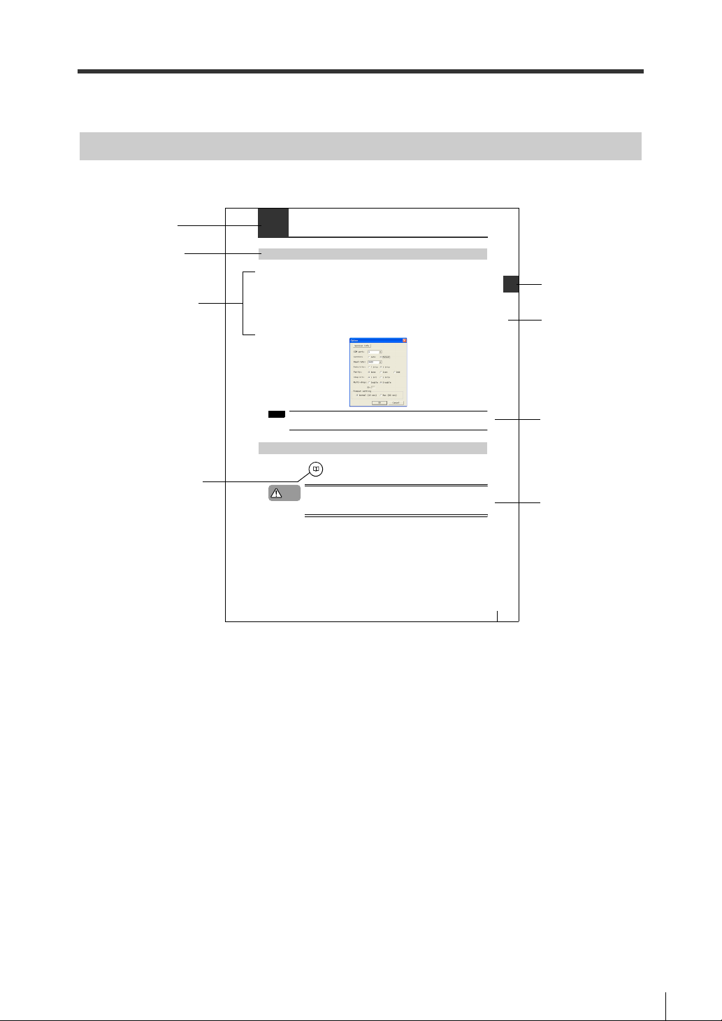
How to Read this Manual
N-410 Settings
3
3-9
3-2
Sending and Receiving Settings
Sending settings to the N-410
The changed settings are forwarded to the N-410. Perform the following steps.
1
Press and hold the N-410 dipswitch for 8 seconds.
When the N-410 display shows "SO (50)", the communications state is as follows.
·
Baud rate: 115200 bit/s · Stop bit: 1 bit
·
Data bits: 8 bit
·
PLC link: None
·
Parity: Even
2
Click the [Option] button on the AutoID Navigator, then make the settings for "COM port."
Make sure that the communication settings for the computer are compatible with those made in step
1. Click the [OK] button when settings are finished.
If "Multi-head mode" is selected, create the network using BL series devices
exclusively or using RF series devices exclusively.
Controlling Multi-head Mode
Sending commands to the N-410 and to BL/SR/RF series devices is the same as in multi-drop
link mode. Refer to "4-1 Multi-drop Link Mode" (pag e 4-2) for more information.
Use normal (sequential) notification if you have both N-48/BL-U1 and NX-
50RS power supplies on the network.
Note
Caution
This is a note.
These notes indicate
operations or
procedure where
errors are common.
Make sure to read
these carefully.
This is a large
headline.
This is the chapter
title.
This is a reference to
a different page or
manual. Related
information can be
found in the location
indicated.
This is a medium
headline.
These are operating
instructions.
* This page was created for the purposes of this explanation and is thus
different from any actual page in this manual.
This is an index.
There is one for each
chapter.
This is a caution.
There is a risk of
damage or breakage
if the information in
these sections is not
heeded.
This section explains the layout of each page and the symbols and words used in the manual.
Page Layout
9
Page 12
Terms
The explanations in this manual use the following terms frequently.
Ter m Meaning
N-410 This indicated the N-410 RS-485 master unit.
BL Series This indicates a BL Series barcode reader.
RF Series This indicates an RF-500 Series RFID system.
N-48 This indicates an N-48 24 V DC communication unit (RS-485 output).
BL-U1 This indicates a BL-U1 100 V AC communication unit.
NX-50RS This indicates an NX-50RS network controller.
AutoID Navigator This indicates the AutoID Navigator general AutoID system setting software.
SR-500 Series This indicates an SR-500 Series 2D code reader.
N-R4 This indicates an N-R4 24 V DC communication unit.
Symbols
The explanations in this manual indicate menus and buttons with the following symbols.
Symbol Meaning
[ ] This indicates a tab or menu in the setting software, or a button name in a dialog box.
" "
This indicates setting items, titles of sections within this manual, the name of a different
manual with relevant information, or words that have been emphasized.
10
Page 13

1
N-410 Overview
This chapter outlines the features and functions of the N-410, as well as the
part names and the required system architecture.
1-1 What You Can Do with the N-410 . . . . . . . . . . . . . . 1-2
1-2 System Configuration . . . . . . . . . . . . . . . . . . . . . . . 1-4
1-3 Part Names . . . . . . . . . . . . . . . . . . . . . . . . . . . . . . . 1-5
1-1
Page 14
1
1-1 What You Can Do with the N-410
N-410
RS-485
BL/SR/RF Series
RS-232C
Host computer
Trigger sensor
N-R4
N-48
BL-U1
or
NX-50RS
Note
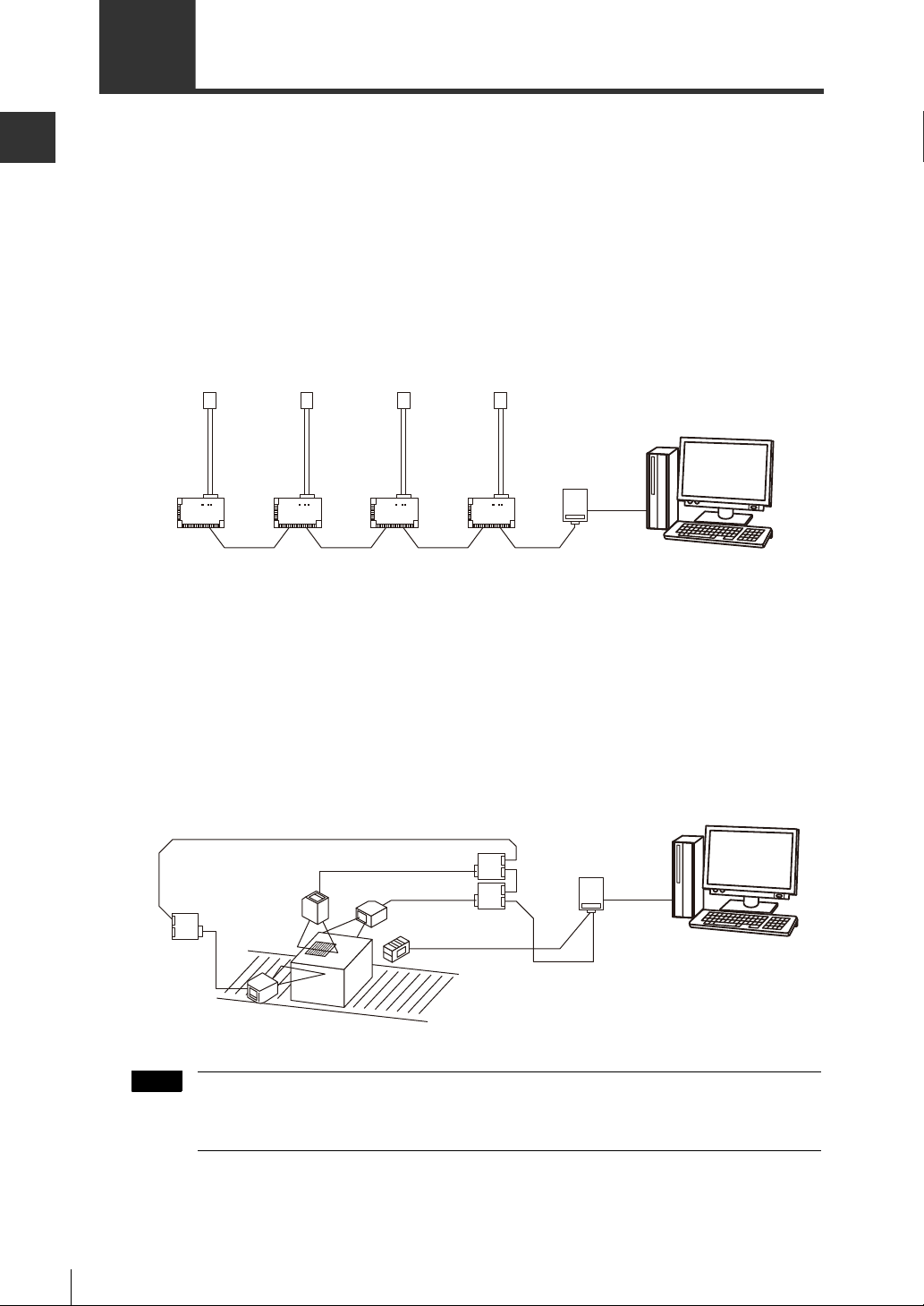
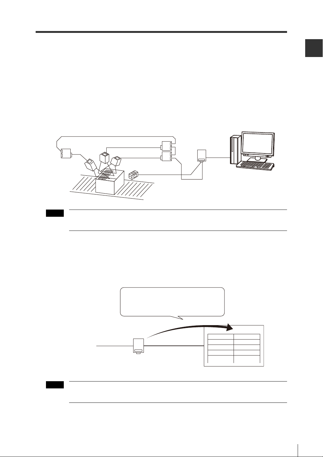
The N-410 allows you to add the following functions to any BL/SR/RF Series device.
N-410 Overview
Multi-drop Link mode
The N-410 allows you to control up to 31 BL/SR/RF Series devices for each host computer. This is
called "multi-drop link".
Communications are over RS-485, making longer distances (up to 1.2 km) possible with high
noise resistance. The connection is through a twist-pair cable (two lines), meaning that minimal
wire is used.
To allow the N-410 to control communication with each BL/SR/RF Series device, the host
computer should be set up to communicate only with the N-410. This uses a very simple program
(The BL/SR/RF Series device that sent each packet of data is identified by an ID number
appended to the head of the packet). The system can thus be constructed so that load on the
host computer is extremely low.
Multi-head mode
If the location of the code or IC tag on a product is unknown or there are multiple codes or IC
tags on a product, more than one unit will be needed to read the information. In these cases,
multiple devices will be needed to scan for barcodes or IC chips in multiple locations or from
multiple angles.
The N-410 can be used in multi-head mode in these cases to allow the host computer to control
multiple BL/SR/RF Series device as one unit.
The number of units that can be connected and the distance over which they can be connected
are the same as for multi-drop link mode, up to 31 units over 1.2 km.
N-R4
N-48
BL-U1
or
NX-50RS
BL/SR/RF
Series
N-410
RS-232C
RS-485
Host computer
1-2
• BL Series, SR Series, and RF Series devices cannot be connected at the same time in
multi-head mode.
• An NX-50RS Series device cannot be connected to an SR-600 Series device.
Page 15
1-1 What You Can Do with the N-410
1
Note
N-410
PLC
DM103
DM104
DM105
DM106
BL Series
SR Series
...
4
$30
$31
$32
...
The N-410 forwards the data read with a
code reader directly to the
PLC memory, so no communication
program is required.
Note
Interference suppression function
(when using a network in multi-drop mode with only BL/SR Series devices)
If the code readers must be positioned very close to each other, such as when reading a
multistage label, as shown below, their light sources may interfere with one another and have a
negative effect on the reading.
The interference suppression function activates the code reader lasers (LEDs) one after another,
thus preventing interference and stabilizing the reading.
Because the lasers are activated in an ordered fashion, the amount of time each laser (LED)
spends deactivated increases as the number of lasers connected increases. If the line speed is
too fast, the laser array may nor be able to make readings.
N-410 Overview
N-410
RS-232C
Host computer
RS-485
N-R4
N-48
BL-U1
or
NX-50RS
BL Series
SR Series
Trigger sensor
• This cannot be connected to RF Series devices.
• An NX-50RS Series device cannot be connected to an SR-600 Series device.
PLC link function (when using a network with only BL/SR Series devices)
The PLC link function allows data from a code reader in multi-drop link mode or multi-head mode to be
forwarded directly to a PLC without a program.
This helps reduce the number of man hours devoted to PLC programming.
• This cannot be connected to RF Series devices.
• An NX-50RS Series device cannot be connected to an SR-600 Series device.
1-3
Page 16
1
1-2 System Configuration
N-410
RS-485
RS-232C
Trigger sensor
N-R4
N-48
BL-U1
or
NX-50RS
AutoID
Navigator
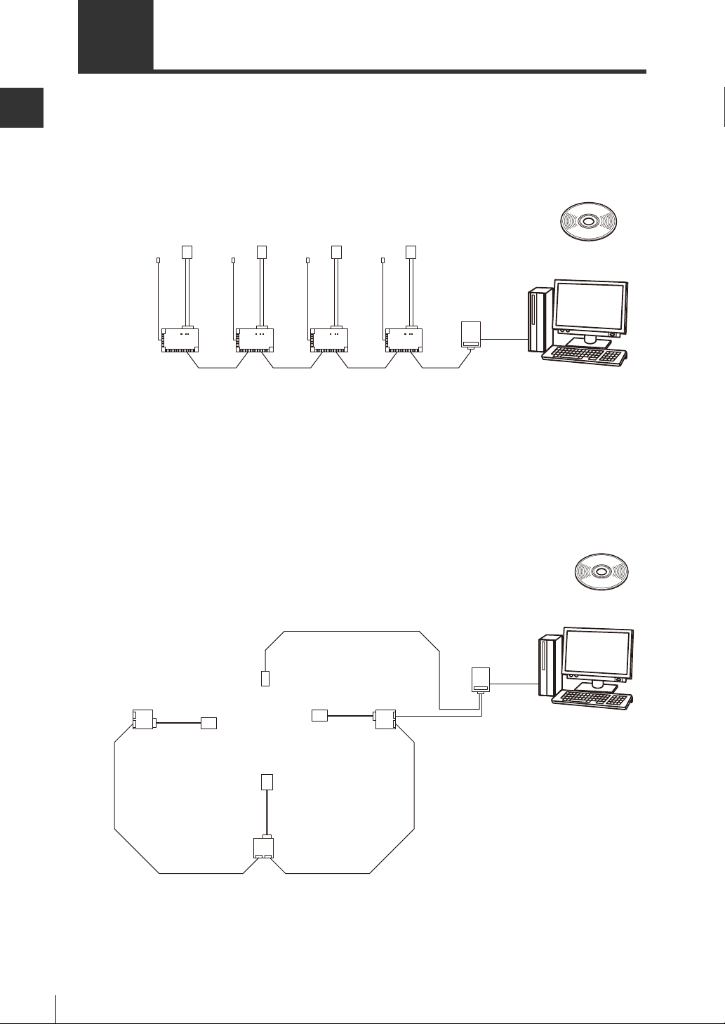
The system configuration for using the N-410 is as follows. The configurations for multi-drop
link mode and multi-head mode will be explained separately.
N-410 Overview
For multi-drop link mode
• Maximum devices connected: 31
• Maximum connection distance: 1.2 km
Trigger
sensor
N-R4
N-48
BL-U1
or
NX-50RS
N-410
RS-232C
RS-485
AutoID
Navigator
* The settings for the N-410 are made with the AutoID Navigator.
* The devices that can be connected are the BL-1300/700/600/500/180/210 Series, the SR-500/
600 Series, and the RF-500 Series.
* The N-410, N-R4, N-48 and NX-50RS all requires a 24 V DC power source.
For multi-head mode (including using interference suppression)
• Maximum devices connected: 31
• Maximum connection distance: 1.2 km
* Connect a trigger sensor to the N-410.
* The devices that can be conned are the BL-1300/700/600/500/180/210 Series, the SR-500/600
Series, and the RF-500 Series.
* The N-410, N-R4, N-48 and NX-50RS all requires a 24 V DC power source.
1-4
Page 17
1
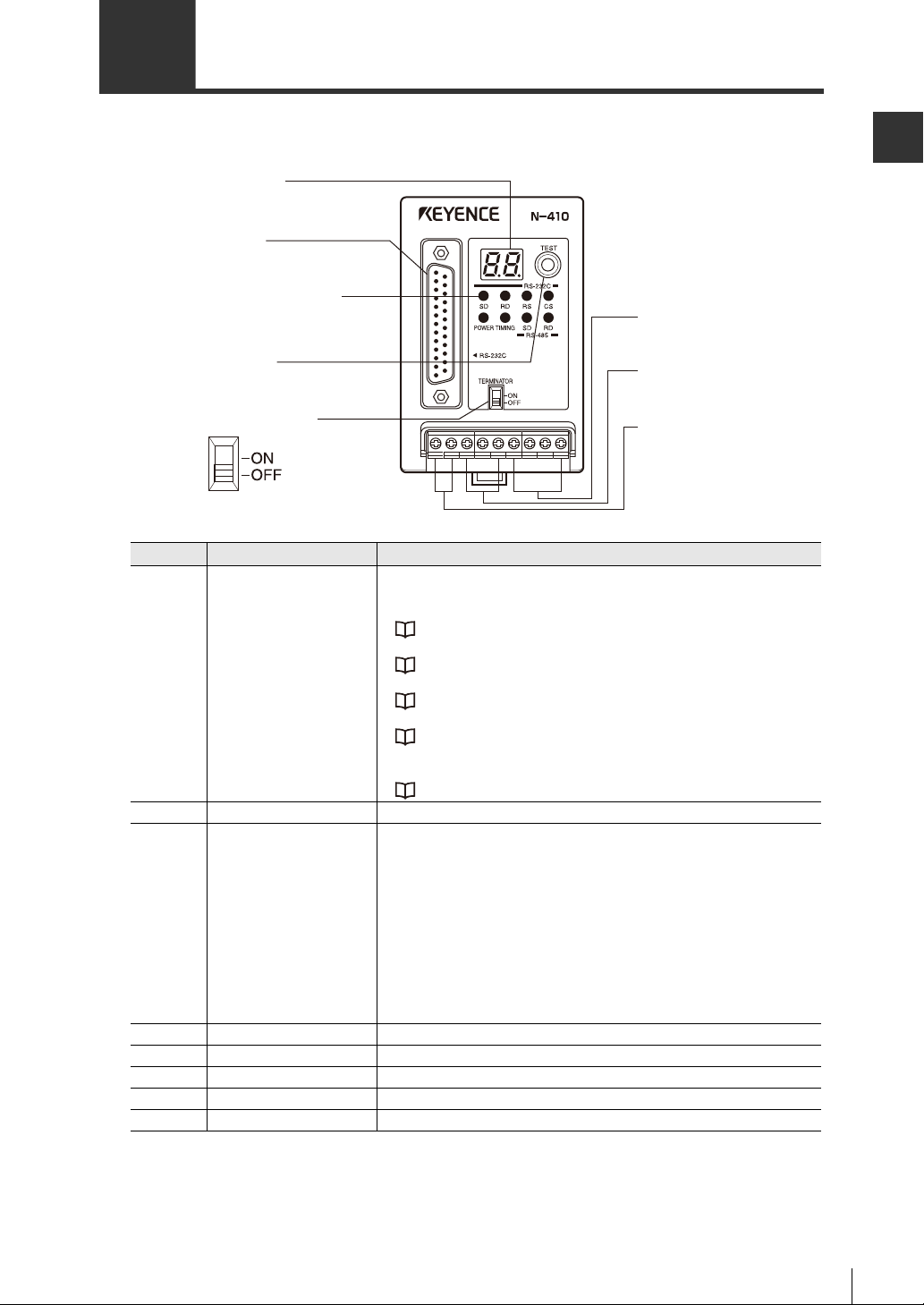
1-3 Part Names
1. Display LED
6. Power terminal
7. RS-485 terminal
8. Trigger input terminal
2. RS-232C
3. Communication state
display LEDs
4. Test switch
5. Terminator switch
N-410
Number Name Function
• Normally displays the ID number of the N-410, which is 00.
• Displays the ID number of any device undergoing a connection
.
test
"2-7 How to Use the Connection Confirmation Test" (Page 2-31)
• Displays "55" during setting mode.
1 Display LED
2 RS-232C Connects the host computer to the PLC.
Communication state
3
display LEDs
4 Test switch Activates test switch mode.
5 Terminator switch Toggles the terminator.
6 Power terminal Connects a 24 V DC power source.
7 RS-485 terminal Connects for multi-drop.
8 Trigger input jack Used for trigger input in multi-head mode.
"4-5 N-410 Setting Commands" (Page 4-22)
• Displays "50" while initiating communications to change settings.
"3-2 Sending and Receiving Settings" (Page 3-9)
• Displays the error state of the N-410.
"Appendix 4 Main device display" (Page A-12)
• Displays the ID number of the currently communicating device
when sending hotline commands.
"Specifying the ID number to send commands to" (Page 4-20)
• Power: Illuminates when power is on.
• Timing:Illuminates when the N-410 is receiving timing signals.
Illuminates when connected to a normal open point and is on.
Illuminates when connected to normal close point and is off.
(RS-232C)
SD, RD, RS, CS: Illuminates when there is communication over the
RS-232C port.
(RS-485)
SD: Illuminates when sending data
RD: Illuminates when receiving data
* When sending and receiving data, both SD and RD illuminate.
N-410 Overview
1-5
Page 18
1
1-3 Part Names
1. Head port
2. Power LED
4. RS-422A/485 connector
5. I/O status LED
6. I/O terminals
7. Power terminal
8. DIN rail mounting tab
9. RS-422A/485
changeover switch
3. Communication status LED
10.Terminating
resistance switch
N-R4
N-410 Overview
States of RS-422A/485 changeover switch and terminating resistance switch
Number Name Function
1 Head port Used to connect the head.
2 Power LED Lights when the power is ON.
Communication status
3
LED
4 RS-422A/485 connector Used to connect to the host (personal computer, PLC).
5 I/O status LED Monitors the ON/OFF status of the I/O terminals.
6 I/O terminals Used to connect I/O signal lines of control units.
7 Power terminal Terminal for 24 V DC power supply input.
8 DIN rail mounting tab Used to secure the N-R4 to a DIN rail.
RS-422A/485
9
changeover switch
Terminating resistance
10
switch
Number
1 Left Right 2 Left Right 3- - Right
RS-422A
communication mode
Monitors the status of communication with the head.
Used to switch between RS-422A and 485 communications.
Used to switch between ON and OFF for terminating resistance.
RS-485
communication mode
Terminating
resistance ON
* Factory settings are by default RS-485 communication and the terminating resistance set to the
OFF position.
1-6
Page 19
1
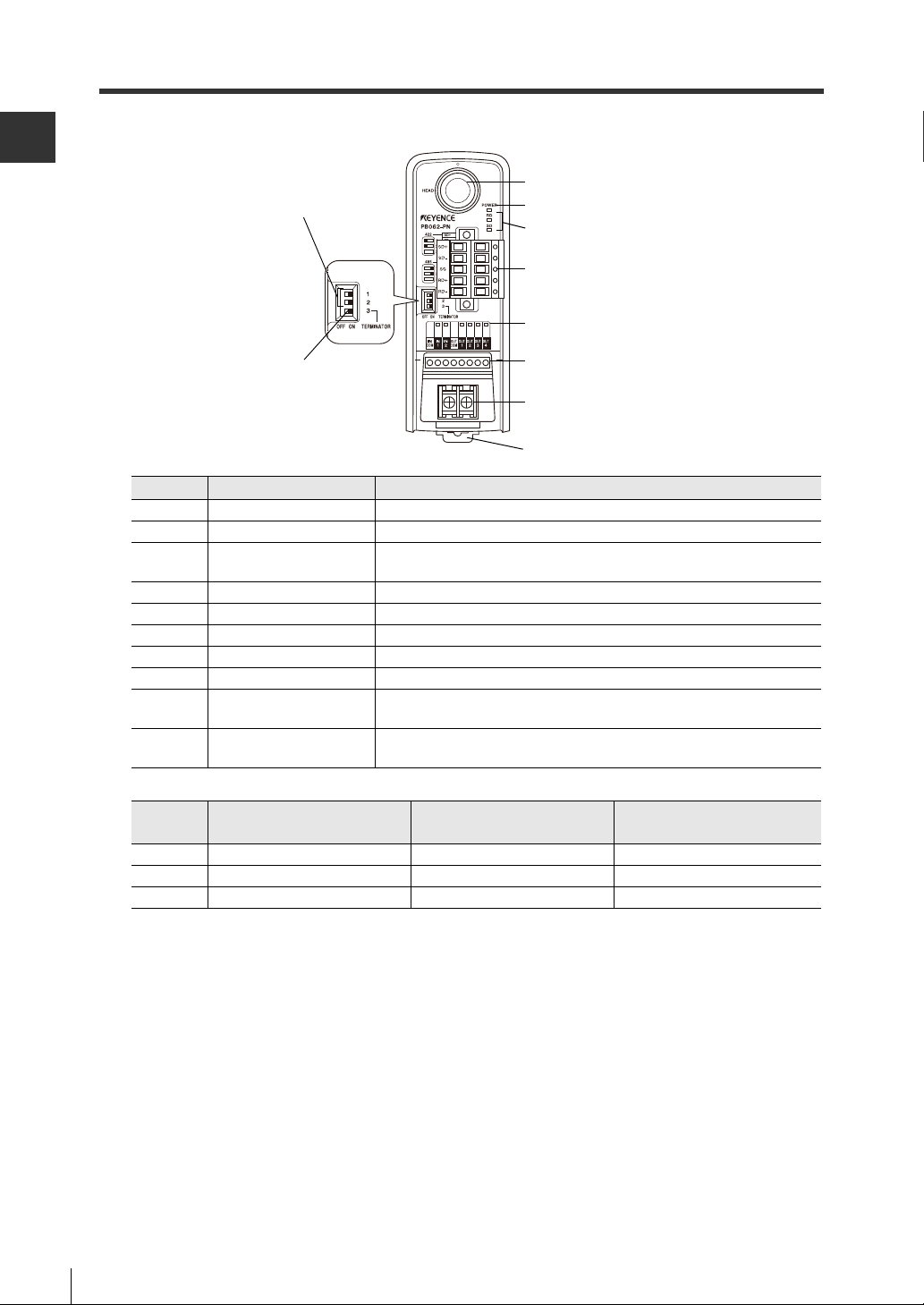
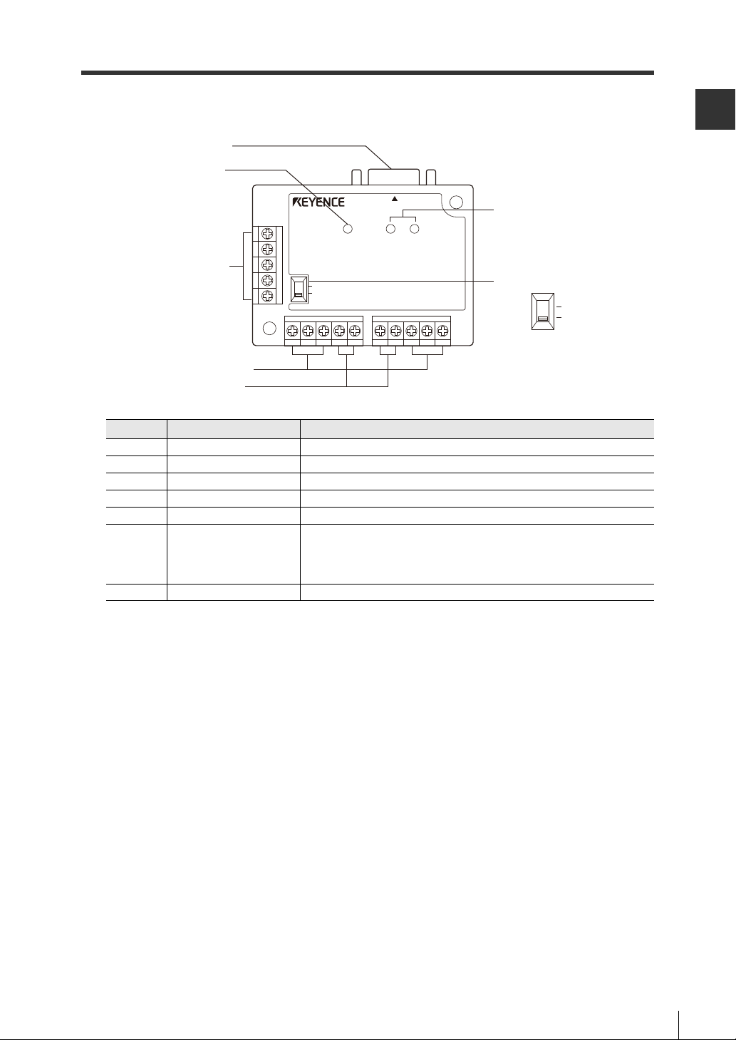
N-48
1-3 Part Names
1. Reader port
2. Power LED
READER
SD RD
N-48
3. Input/output
terminal
TERMINATOR
ON
OFF
POWER
4. RS-485 terminal
5. Power terminal
Number Name Function
1 Reader port Connects to BL/SR/RF Series devices.
2 Power LED Illuminates when power is on.
3 Input/output terminal There are terminals for input and OK/NG output.
4 RS-485 terminal Used for multi-drop connections.
5 Power terminal Connects a 24 V DC power source.
Monitors the state of communications at the reader port.
Communication state
6
display LEDs
7 Terminator switch Toggles the terminator.
SD: Illuminates when a BL/SR/RF Series device sends data.
RD: Illuminates when a BL/SR/RF Series device receives a
command.
6. Communication
state display LEDs
7. Terminator switch
ON
OFF
N-410 Overview
1-7
Page 20
1
1-3 Part Names
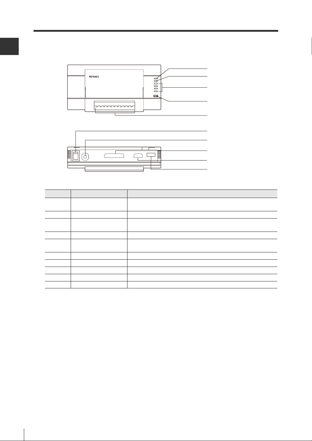
BL-U1
N-410 Overview
1. OK/NG LED
2. Timing LED
3. Communication
state display LEDs
4. Power LED
5. Input/output terminal
6. Power switch
7. Power cable(2m)
8. RS-232C port
9. Reader port
10. Dipswitch
Number Name Function
1OK/NG LED
2 Timing LED Illuminates when trigger input is on.
Communication state
3
display LEDs
4 Power LED Illuminates when power is on.
5 Input/output terminal
6 Power switch Turns the power on or off.
7 Power cable (2m) Use 100 to 240 V AC(50 / 60 Hz).
8 RS-232C port Connects to the computer. Not used for multi-drop connections.
9 Reader port Connects to BL/SR/RF Series devices.
10 Dipswitch Changes communication ports, toggles the terminator.
•Illuminates green when output is OK.
•Illuminates red when output is NG.
Monitors the state of communications at the RS-232C port.
From top to bottom: SD, RD, RS, CS
There are terminals for trigger input, OK/NG output, RS-422A and
RS-485.
1-8
Page 21
1
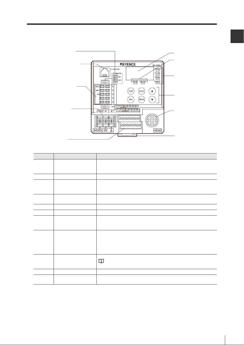
NX-50RS
1. Terminator switch
2. RS-232C connector
3. RS-485 connector
4. Power terminal
5. Input/output
terminal
6. Display
7. Network
communication
state LED
8. Head
communication
state LED
10. Head connector
11. DIN rail
mounting bracket
9. Control switch
Front panel
1-3 Part Names
N-410 Overview
Number Name Function
Toggles the terminator.
Terminator switch
1
RS-232C connector Used to connect to a computer.
2
RS-485 connector
3
Power terminal
4
Input/output terminal Connects input devices such as PLC via NPN/PNP.
5
Display Displays the status of the network controller.
6
Network communication
7
status LED
Head communication
8
state LED
Control switch
9
Head connector Connects to the head or the code reader.
10
DIN rail mounting
11
bracket
Turns on when the network controller is at the end of the main line. Turns off
at all other times.
Used to connect to a field network.
Used when connecting a device such as a network controller to a
multi-drop connection.
Used to connect to a 24 V DC power supply. Use a D type ground for
the FG pin.
Displays the communication status of the network.
SD/RD: Displays whether data is being sent or received.
Online: Displays whether the device is online.
Displays the communication status of the head via LED.
Access: Illuminates when the head is communicating.
M1/OK: Illuminates when the head is outputting an OK signal.
M2/NG: Illuminates when the head is outputting an NG signal.
M3/ERR: Illuminates when the head is outputting an error signal.
Used to control the network.
"RF-500 Series Setup and Connection Manual" "4-1 Network Controller
Functions"
Mounting bracket for DIN rails.
1-9
Page 22

1
1-3 Part Names
N-410 Overview
MEMO
1-10
Page 23

2
Installation
This chapter describes how to connect the N-410 and confirm the
connection.
2-1 Making Settings and Connections . . . . . . . . . . . . . 2-2
2-2 N-410 Connections and Wiring. . . . . . . . . . . . . . . . 2-5
2-3 Connecting and Wiring to the N-R4 Series. . . . . . 2-10
2-4 NX-50RS Connections and Wiring . . . . . . . . . . . . 2-16
2-5 N-48 Connections and Wiring. . . . . . . . . . . . . . . . 2-20
2-6 BL-U1 Connections and Wiring . . . . . . . . . . . . . . 2-26
2-7 How to Use the Connection Confirmation Test . . . 2-31
2-8 Installation . . . . . . . . . . . . . . . . . . . . . . . . . . . . . . . 2-32
2-1
Page 24

2
2-1 Making Settings and Connections
Use the following steps for installation.
<Required items>
• RS-485 master unit N-410
Installation
• BL Series barcode reader, SR Series 2D code reader, RF Series RFID system
The following units are compatible with the N-410.
BL Series- BL700/600/500/180/210 Series
SR Series- SR-500, SR-510
RF Series- RF-500, RF-550
• RS-485 power source for multi-drop (N-48, BL-U1, NX-50RS)
Each BL/SR/RF Series device requires its own communication unit.
• RS-232C type communication unit (BL-U2)
When using an N-48 to power a multi-drop network, a separate communication unit will be
required to change settings on any of the BL/SR/RF Series devices because the N-48 does
not include an RS-232C.
This is not required when using a BL-U1 or an NX-50RS to power a multi-drop network.
• RS-232C cable for N-410
This cable connects the N-410 to the host computer.
Be sure to use a cable with the proper pin settings for the computer or PLC that you are using.
• RS-232C cable for BL/SR/RF Series settings
This is the cable used to connect the computer, BL-U1, BL-U2 or NX-50RS to the computer
when changing settings on a BL/SR/RF Series device. This cable is different than the RS-232C
cable for the N-410 and must be prepared separately.
Refer to the user’s manual for each device for more information about wiring.
• Twist pair cable for RS-485
Use this for the settings cable.
"Wiring an RS-485" (Page 2-24)
"Wiring an RS-485" (Page 2-30)
•Host computer
Use a computer with an RS-232C.
It is possible to exceed the data handling capacity of the host computer when large amounts
of data are being sent from multiple BL/SR/RF Series devices.
In such cases, reduce the number of BL/SR/RF Series devices connected or use a host
computer with a higher data handling capacity.
2-2
Page 25
2-1 Making Settings and Connections
2
<Making Settings and Connections>
1. Set BL Series , SR Series, and RL Series devices
Use the BL/BL 210 Series AutoID Navigator software to change the settings on BL/SR/RF
Series devices. This requires preparing the BL/SR/RF Series devices, the communication unit
for an RS-232C (N-R2, BL-U1, BL-U2 or NX-50S), an RS-232C cable for changing BL/SR/RF
settings and a computer.
Refer to the user’s manual for each device for more information making settings and
connections.
The necessary settings vary greatly depending on the mode being used. Refer to the following
pages.
• Multi-drop Link mode "Settings" (Page 4-3)
• Multi-head mode "Settings" (Page 5-3)
2. Set the N-410
Use AutoID Navigator and the N-410, RS-232C cable for the N-410 and the computer to make
the settings. For more information on using AutoID Navigator, refer to the "AutoID
Navigator User's Manual".
The necessary settings vary depending on the mode being used. Refer to the following pages.
• Multi-drop Link mode "N-410 Settings" (Page 4-4)
• Multi-head mode "N-410 Settings" (Page 5-4)
• PLC link "7-1 PLC Link" (Page 7-2)
Installation
3. Set the host computer and PLC control
Change the settings for baud rate, data bits and stop bit length to match the RS-232C side of
the N-410 settings.
When using a PLC link, refer to "7-3 Settings" (Page 7-13) , then make the settings.
4. Connect BL/SR/RF Series devices to the N-410
First, connect a the BL/SR/RF Series device to a dedicated communication unit (N-R4, N-48,
BL-U1 or NX-50RS).
Then connect the communication unit to the N-410 with the specified cable, (RS-485, twist
pair). Set the terminator settings on both devices to on.
When using a BL-U1, be sure to set the dipswitch to "RS-485".
5. Connect the N-410 to the host computer or the PLC
Be sure that the RS-232C cable you are using has a pin layout compatible with your PLC or
host computer.
6. Confirm that the N-410 and BL/SR/RF Series devices are correctly connected by RS-485
The connection test mode will confirm if the N-410 and RS-485 are connected correctly and if
the AutoID Navigator is set correctly. Use it to confirm that the RS-485 connection is set up
correctly. Refer to "2-7 How to Use the Connection Confirmation Test" (Page 2-31) for more
information.
7. Connect the trigger sensor
Connect one trigger sensor for each power source.
(This is not necessary if reading operation is controlled by reading start and stop commands)
When used in multi-head mode, one trigger device is required for the N-410.
(This is not necessary if reading operation is controlled by reading start and stop commands)
Multi-head mode will not operate properly if a trigger sensor is connected to anything other than the
N-410.
2-3
Page 26

2
2-1 Making Settings and Connections
8. Confirm operation
Test the RS-232C connection between the N-410 and the host computer with the terminal
software in AutoID Navigator.
When using a PLC link, make sure that data is being input to PLC memory.
Installation
2-4
Page 27
2
2-2 N-410 Connections and Wiring
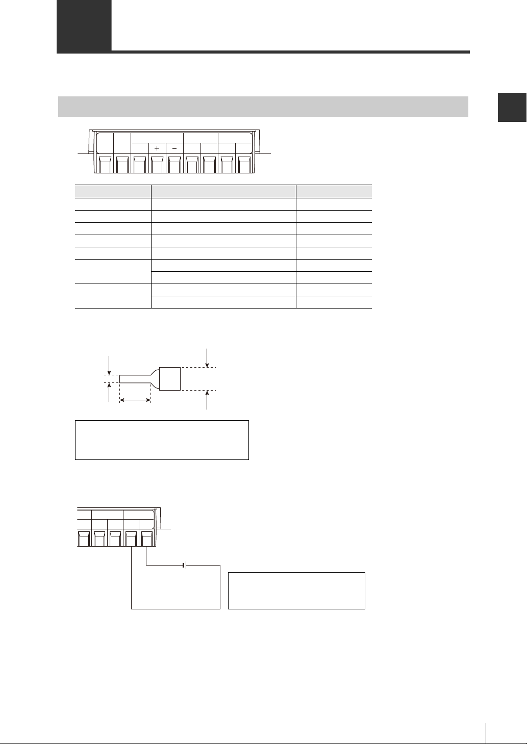
5 mm max.
6 mm min.
2.0 mm
max.
Recommended manufacturer:
Maker: JST Manufacturing Company, Ltd.
Model: VTUB-1.25
–
DC OUT DC IN
24V DC
+
24V 0V 24V 0V
Use an NEC class 2 output
power source for UL
certification.
This section explains how to connect the N-410 to other devices.
Installing and Wiring the Input and Output Jacks
TIM COM
RS-485
SG 24V 0V 24V 0V
Symbol Explanation Signal direction
TIM Trigger input Input
COM Trigger input common Input
RS-485 SG RS-485 ground signal RS-485 + RS-485 + side Input/output
RS-485 - RS-485 - side Input/output
DC OUT
DC IN
24 V DC power source output + side Output
24 V DC power source output - side Output
24 V DC power source input + side Input
24 V DC power source input - side Input
* These appear in this order from left to right on the terminal.
DC OUT DC IN
Installation
Electrical wiring
• A bar terminal (I terminal) like that shown in the figure can be used.
Connect the N-410 to a 24 V DC power supply.
Connect the 24 V DC power source to the "IN" side of the power terminal to use the "OUT" side of
the terminal as a 24 V DC power supply (However, be certain that the power supply coming into
the "IN" side is will have enough power to power the device connected to the "OUT side").
2-5
Page 28
2
2-2 N-410 Connections and Wiring
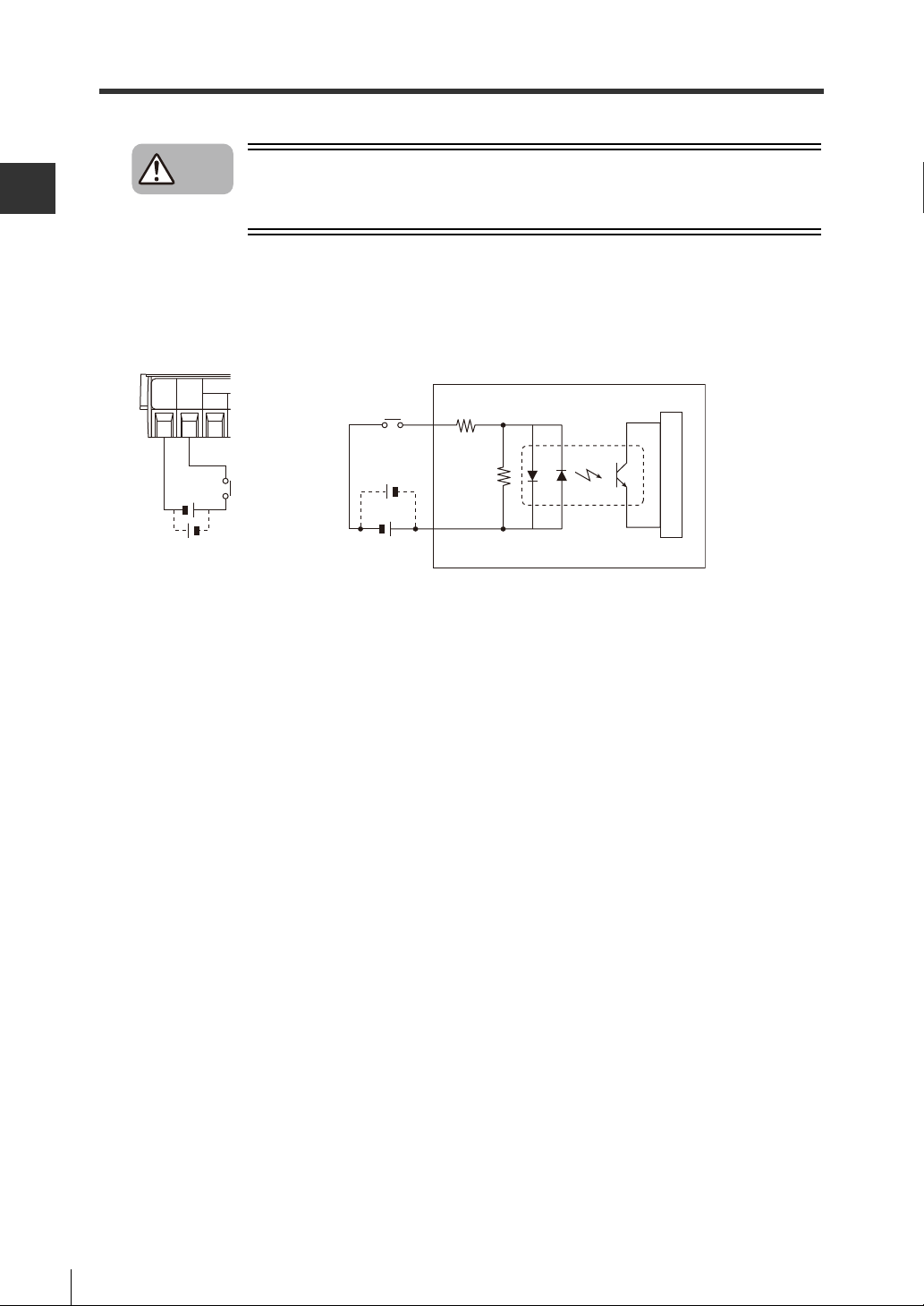
TIM COM
SG
+
+
Contact
or
non-contact
15 to 26V DC
+
+
Circuit diagram
Internal circuit
TIM
COM
Caution
Be sure to use only 24 V DC power for this device. Usage of any other power
supply, including AC power, may damage this device.
Installation
Wiring the trigger input
When used in multi-head mode, the timing device should be connected to the N-410, not the BL/
SR/RF Series devices.
2-6
Page 29

2
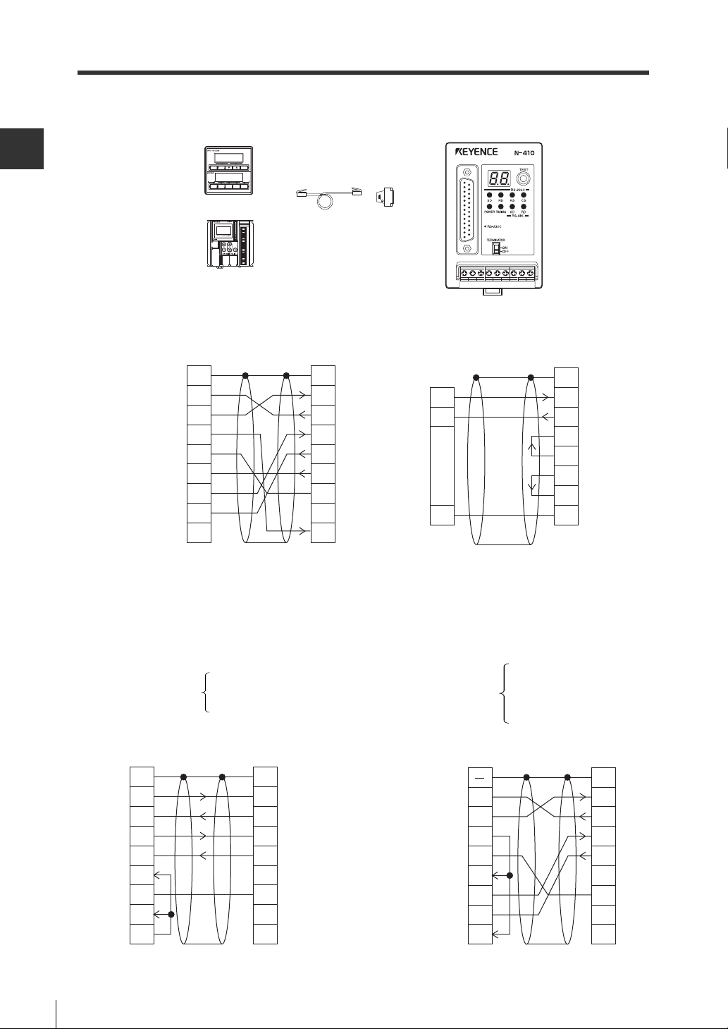
RS-232C Connections
13
25 14
1
D-sub 25 pin (female)
DCE specification
(modem definition)
M2.6 screws
Connecting to a DOS/V computer
FG
SD
RD
RS
CS
DR
SG
N-410
-
Connector case
2RD
3SD
4ER
5SG
6DR
7RS
8CS
DOS/V
CD 1
1
2
3
4
5
6
7
8
ER20
D-sub 9 pin (female)
#4-40 screws
D-sub 25 pin (male)
M2.6 screws
* A KEYENCE OP-29860 option cable
(1.5m) can be used.
Reference
<Pin Layout>
2-2 N-410 Connections and Wiring
Installation
Pin number Symbol Function
1 FG Frame ground 2 SD (TXD) Receive data Input
3 RD (RXD) Send data Output
4 RS (RTS) Send capability Input
5 CS (CTS) Request send Output
6 DR (DSR) Connects internally with pin #20 Output
7 SG Signal ground -
20 ER (DTR) Connects internally with pin #6 Input
<RS-232-C cable wiring>
Connecting to a computer
Signal
direction
Standard straight cables (D-sub 25 pin or D-sub 25 pin - 9 pin) can be used.
2-7
Page 30
2
2-2 N-410 Connections and Wiring
-
2
3SD
4ER
5SG
6DR
7RS
8
1
2
3
4
5
6
7
8
CS
FG
SD
RD
RS
CS
DR
SG
9 20-ER
KV-L20V N-410
D-sub 9 pin (female)
#4-40 screws
D-sub 25 pin (male)
M2.6 screws
Connector case
RD
3SD
5RD
1
1
2
3
4
5
6
20
7
SG
FG
SD
RD
RS
CS
DR
ER
SG
KV-L20V
N-410
Jack
D-sub 25 pin (male)
M2.6 screws
Port 1 Port 2
* A KEYENCE OP-29860 option cable
(1.5m) can be used.
Connecting to a
AJ71UC24
AJ71QC24N/-R2
Connector case
2RD
3SD
4ER
5SG
6DR
7RS
8
1
2
3
4
5
6
7
8
CS
FG
SD
RD
RS
CS
DR
SG
1 20CD ER
MELSEC N-410
D-sub 9 pin (male)
M2.6 screws
D-sub 25 pin (male)
M2.6 screws
A1SJ71UC24-R2/PRF
Connecting to a AJ71QC24N/-R2
QJ71C24N/-R2
Connecting to a KV Series programmable controller port
Use a KEYENCE option cable.
RESET ENTER
Installation
NEXT
F1 F2 F3 F4 F5
KV-10/16/24/40
KV-P
KV-3000/1000/700
OP-24045 (1m)
or
OP-24025 (5m)
OP-26485
Connecting to a KV-L20V
Connecting to a MELSEC Series device
2-8
MELSEC N-410
1FG
2SD
3RD
4RS
5CS
6DR
7SG
8
CD
20 20ER ER
D-sub 25 pin (male)
M2.6 screws
1
2
3
4
5
6
7
8
D-sub 25 pin (male)
M2.6 screws
FG
SD
RD
RS
CS
DR
SG
Page 31

2
SYSMAC Series
CV Series, CS1 Series, (CPU mounted board)
Connecting to a
CS1W-SCB21 (-V1)/41 (-V1)
CS1W-SCU21 (-V1)
CJ1W-SCU21 (-V1)/41 (-V1)
1FG
2SD
3RD
4RS
5CS
9SG
1
2
3
4
5
7
FG
SD
RD
RS
CS
SG
PLC N-410
D-sub 9 pin (male)
M2.6 screws
D-sub 25 pin (male)
M2.6 screws
2-2 N-410 Connections and Wiring
Installation
2-9
Page 32

2
2-3 C
37485
12
9
1112
6
10
Round 12-pin jack
onnecting and Wiring to the N-R4 Series
Connecting to BL-1300 Series/SR Series/RF Series Devices
Use the N-R4 when connecting an N-410 Series device to a BL-1300 Series/SR Series/RF Series
Installation
device. Connect it in the following way.
Pin layout of the head port
Pin
number
1 OUT1 For OUT1 input Input
2 OUT2 For OUT2 input Input
3 TXD Data transmission Input
4 CTS Transmission permitted Output
5 OUT4 For OUT4 input Input
6 IN2 For IN2 output Output
7 RXD Data reception Output
8 RTS Transmission request Input
9 OUT3 For OUT3 input Input
10 IN1 For IN1 input Output
11 +5V +5V power supply Output
12 GND GND –
Caution
Install and remove connection cables with the power OFF.
Name Signal name
Signal
direction
2-10
Page 33

2-3 Connecting and Wiring to the N-R4 Series
2
Power supply
DC 24VDC
Twisted pair cable
* Although the figure shows the model "N-R2", the power supply
terminals are located in the same position on all models.
+10%
-
20%
Connecting the Power Supply
Connect the 24 VDC power supply to the power supply terminal block as shown in the figure.
Installation
Caution
Do not use a power supply other than 24 V DC. Otherwise, product failure
may occur.
Applicable terminals for power supply connection
The dimensions of crimp contacts used for wiring should be as follows:
Terminal Dimensions
Round Terminal a : 6.0 mm Max.
Y terminal a : 6.0 mm Max.
Item Description
Wire size AWG 14 to 22
Tightening torque 0.49 N·m (4.34 lbf·in)
Wire material Copper
Wire type Stranded wire
Electric wire
temperature rating
+60°C
2-11
Page 34

2
2-3 Connecting and Wiring to the N-R4 Series
* Although the figure shows the model
"N-R2", the I/O terminals are located in
the same position on all models.
Reference
1.5 mm max.
5 mm max.
3.5 mm max.
Circuit diagram
IN1, IN2
INCOM
Internal
circuit
I/O Terminal Layout and Wiring
I/O terminal layout
Installation
These terminals are used to connect I/O devices such as a PLC.
Symbol Description
INCOM Common for IN terminal –
IN1
IN2
OUTCOM Common for OUT terminal –
OUT1
OUT2
OUT3
OUT4
Used as an input terminal for
the code reader.
Used as an output terminal from
the code reader.
Caution
• For connection, use stranded copper wire with a gauge of AWG16 to 26.
• Limit the tightening torque for the terminal block screws to 0.19 N•m (1.7
Lbf•in) or less.
Standard The power supply terminal block and the I/O terminal block are insulated from each other.
The INCOM and OUTCOM terminals are insulated from each other.
Signal
direction
Input
Output
Applicable crimp terminal
Use a bar terminal with the following dimensions for the connection.
Wiring the IN1 and IN2 terminals
The IN1 and IN2 terminals are used to input trigger signals, to preset registration data, or to send
laser emission stop signals.
The inputs are energized when 15 to 26.4 V DC is connected between the corresponding input terminals
2-12
.
Page 35

2-3 Connecting and Wiring to the N-R4 Series
2
Photoelectric sensor
Brown (Red)
Black (White)
Blue (Black)
Load
Load
Load
Load
OUT1 to OUT4
OUTCOM
Load
Circuit diagram
Internal circuit
PLC
Connection to a photoelectric sensor manufactured by KEYENCE
For this connection, the IN1 terminal is used as the trigger input terminal.
Wiring the OUT 1 through OUT 4 terminals
The OUT terminals can be used to verify OK/NG readings, and other status outputs from the BL-1300
Series.
The output form is photo MOS relay.
Installation
Connection to a PLC (programmable logic controller) manufactured by
KEYENCE
2-13
Page 36

2
2-3 Connecting and Wiring to the N-R4 Series
485+
485
SG
Unused
Note
485+
485–
SG
485+
485–
SG
485+
485–
SG
RS-485+
RS-485–
RS-485 SG
N-R4 N-R4 N-R4
N-410
*
Set the terminating resistance switches of the N-R4 and N-410 marked with * to ON.
Note
(With a branch) (No branch)
Terminating resistance switch: ON
Terminal layout of RS-485
Installation
• The extended distance of the cable must not exceed 1.2 km.
• Set the terminating resistance switch (100W) of the N-R4 located at the end of the RS485 trunk line to ON.
• To use the multi-drop connection, the N-410 master unit must be used.
Symbol Description
485+ RS-485 + side I/O
485 RS-485 side I/O
SG Signal ground
Signal
direction
Wiring the RS-485 cable
Use a twisted pair cable for RS-485 connection.
Recommended RS-485 cable
Manufacturer: THE FURUKAWA ELECTRIC CO., LTD.
Product name: Instrumentation cable
Model: KPEV-SB (1P) 0.75 mm
2
N-410 (Multi-drop communication)
• Up to 31 units N-R4 units can be connected to a single N-410.
• Limit the total extension of the RS-485 cables to 1.2 km.
• Do not supply power to the N-R4 from the 24 V DC OUT terminal of the N-410.
• Never use a terminal block connection at a midpoint of the RS-485 cable connection.
• Avoid branching of the RS-485 connection as shown in the figure below.
N-R4
2-14
• Set the baud rate of RS-485 devices to 4800 bit/s or faster.
N-R4 N-410
N-R4
*
N-R4
N-R4
N-410
*
N-R4
Page 37

2-3 Connecting and Wiring to the N-R4 Series
2
RS-422A/RS-485 changeover switch and terminating resistance switch
Before using the N-R4, select either RS-422A or RS-485 communication using the switch on the unit.
Moreover, when the N-R4 is located at the end of the communication line, set the terminating
resistance switch (100 ) to ON.
Set the switches according to the table below.
Installation
RS-422A
Number
* The factory setting is RS-485 communication mode and
terminating resistance OFF.
communication
mode
1 Left Right —
2 Left Right —
3— — Right
RS-485
communication
mode
Ter min ating
resistance
ON
2-15
Page 38

2
2-4 NX-50RS Connections and Wiring
The wiring for the NX-50RS is as follows.
Electrical wiring
Power terminal
Installation
If using a crimp contact, use a device of the following dimensions.
Terminal Dimensions
Round terminal a:8.0 mm Max
Y terminal a:6.0mm Max
Item Contents
Wire size AWG14-20
Clamping torque 0.51 N
Wire material Copper
Wire type Strand wire
Electrical
temperature rating
·m (4.5 lbf·in)
°C
+60
Electrical wiring
Connect a 24 V DC power source to the power terminal, as shown in the figure.
Caution
• Use a class 2 output power source for 24 V power.
• Use a D type ground pin (ground resistance no more than 100 ).
Power supply
24 V DC ±10%
Twist
Protective
grounding
24 V DC 0 V
2-16
Page 39

2-4 NX-50RS Connections and Wiring
2
Note
Reference
Connecting BL Series/SR Series/RF Series devices
• Connecting to a BL-700/600/180 Series/BL-210RK device
Round connector converter cable (NX-CD2M)
• Connecting to a BL-1300 Series/SR Series/RF Series device
Installation
An SR-600 Series device cannot be connected to an NX-50RS device.
Installing and wiring the input and output terminals
Caution
The IN and OUT sections of the input/output terminal and the electrical terminal are
insulated from one another.
Use an AWG 16 to AWG 30 wiring.
NPN connector
PNP connector
2-17
Page 40

2
2-4 NX-50RS Connections and Wiring
For BL-700/600/180 Series devices
Pin name Signal name Explanation
IN1 Trigger input
Installation
IN2 - Not used
INCOM
OUTCOM
OUT1 OK output This pin outputs the signal that the read was successful.
OUT2 NG output This pin outputs the signal that there was an error in reading.
OUT3 - Not used
OUT4 - Not used
Trigger input
common
Control output
common
This is the signal input pin. This is used for trigger input to a BL
Series device.
This is the trigger input common.
This is the output control common.
For SR-500 Series devices
Pin name Signal name Explanation
IN1 Trigger input
IN2 Preset input This is used for preset input to a SR Series device.
INCOM Input common This is the input signal common.
OUTCOM Output common This is the output signal common.
OUT1 OK output
OUT2 NG output This pin outputs the signal that there was an error in preset.
OUT3 ERROR output This pin outputs the signal that there was an error in reading.
OUT4 BUSY output
This is the signal input pin. This is used for trigger input to a SR
Series device.
This pin outputs the signal that the read and the preset were
successful.
This pin outputs the signal that the device is in the waiting state or
the preset registration is complete.
For BL-1300 Series/SR-600 Series/RF Series devices
Pin name Signal name Explanation
IN1
IN2
INCOM
OUTCOM
OUT1
OUT2
OUT3
OUT4
Control input 1
Control input 2
Control input
common
Control output
common
Control output 1
Control output 2
Control output 3
Control output 4
This is the signal input pin.
This is used for an input signal assigned to the head.
This is the input control common.
This is the output control common.
This is the signal input pin.
This is used for an input signal assigned to the head.
2-18
Page 41

2
Wiring an RS-485 controller (NX-50RS)
Note
Twist pair cable for RS-485
RS-232C cable
OP-29860
Recommended RS-485 cable
Maker: Furukawa Electric Co., Ltd.
Part name: Instrumentation cable
Model: KPEV-SB(1P) 0.75 mm
2
Importa
The wiring for the NX-50RS field network connector is as follows.
485+
485–
2-4 NX-50RS Connections and Wiring
Installation
RS-485 connector cables can be up to 1.2 km long.
Example connection
SG
Not used
Signal
Name
485+ Data communication + side
485- Data communication - side
SG Signal ground
Explanation
When connecting an NX-50RS to a network pin, turn the terminator switch on.
2-19
Page 42

2
2-5 N-48 Connections and Wiring
N-48
BL series
READER
POWER
TERMINATOR
ON
SD RD
N-48
N-410
Computer
RS-232C cable
(OP-29860)
RS-485
twist pair cable
D-sub converter cable
(RF-CM2D)
(BL-1300, SR:OP-80616)
6789
12345
D-sub9 pin (male)
DCE specification
(modem definition)
#4-40 screws
Connecting to a BL/SR/RF Series Device
Connect a BL-700/600/180 Series or 210RK device to the reader board of the N-48.
Installation
When connecting a BL-1300 Series/SR Series/RF Series device to the N-48, use a option D-sub
converter cable (RF-CM2D).
* The baud rate of a code reader connected to the N-48 should be 38400 bps or less.
Pin Layout
Pin number Symbol Function
1 TIM Trigger input Output
2 RD (RXD) Send data Output
3 SD (TXD) Receive data Input
4 OK OK Input
5 GND (SG) Ground (Common ground for all signals) 6 NG NG Input
7 RS (RTS) Send capability Input
8 CS (CTS) Request send Output
9 +5V 5 V power source output (600mA) Output
Signal
direction
2-20
Page 43

2-5 N-48 Connections and Wiring
2
* View from the left side
of the device
* View from the underside
of the device
5 mm max.
6 mm min.
2.0 mm
max.
(Recommended maker) • Maker: JST Manufacturing Company, Ltd.
• Model: VTUB-1.25
Installing and Wiring the Input and Output Jacks
TIM COM OK NG COM
Symbol Explanation
TIM Trigger input Input
COM Trigger input common Input
OK OK output Output
NG NG output Output
COM Output common -
RS-485 RS-485
SG SG
24V DC OUT 24V DC IN
Symbol Explanation
RS-485 SG RS-485 ground signal RS-485 + RS-485 + side Input/output
RS-485 - RS-485 - side Input/output
24 V DC power source input
24 V DC IN (OUT)
(output) + side
24 V DC power source input
(output) - side
Signal
direction
Signal
direction
Input (Output)
Input (Output)
Installation
• A bar terminal (I terminal) like that shown in the figure can be used.
2-21
Page 44

2
2-5 N-48 Connections and Wiring
15 to 26 V DC
TIM COM OK
Electrical wiring
Connect a 24 V DC power source to the "IN" side, as shown in the figure.
If 24 V DC power is connected to the "IN" side, the "OUT" side can be used for 24 V DC output.
Installation
Caution
• Do not connect to any power voltage other than 24 V DC. Doing so may
damage the device.
• Connecting an RS-485 terminal to the wrong power supply may cause
damage to the N-48 unit.
• Do not connect the in and out sides to different types of power sources. A
potential difference between the two power sources could result in
malfunction.
24V DC OUT 24V DC IN
24V DC
Wiring the trigger input
The trigger input is used to cause a BL/SR/RF Series device to begin reading.
When using the device in multi-head mode, use the trigger input from the N-410 instead of the N-
48.
Circuit diagram
TIM
Internal circuit
COM
2-22
Page 45

2-5 N-48 Connections and Wiring
2
Circuit diagram
Internal circuit
OK/NG
COM
Load
Wiring OK/NG output
A signal indicating whether the comparison of preset data was OK or NG is used as the OK/NG
output that indicates whether a BL/SR/RF Series device was able to make a reading.
OK NG COM
Load
Load
* Rated load: 30V DC (100 mA) max.
Installation
2-23
Page 46

Installation
2
N-48
RS-485 SG
RS-485 +
RS-485 –
24V DC IN +
24V DC IN –
24V DC OUT –
24V DC OUT +
RS-485 –
RS-485 +
RS-485 SG
N-48
RS-485 SG
RS-485 +
RS-485 –
24V DC IN +
24V DC IN –
24V DC OUT –
24V DC OUT +
RS-485 –
RS-485 +
RS-485 SG
N-48
RS-485 SG
RS-485 +
RS-485 –
24V DC IN +
24V DC IN –
24V DC OUT –
24V DC OUT +
RS-485 –
RS-485 +
RS-485 SG
TIM
COM
RS-485 SG
RS-485 +–
RS-485 –
24V DC OUT +
24V DC OUT –
24V DC IN +
24V DC IN –
N-410
*
+
24V DC+
24V DC
24V DC
+
24V DC+
Shield
Twist pair cable
Shield
Twist pair cable
Recommended RS-485 cable (shielded)
Maker: Furukawa Electric Co., Ltd.
Part name: Instrumentation cable
Model: KPEV-SB(1P) 0.75 mm
2
*
2-5 N-48 Connections and Wiring
Wiring an RS-485
Use the "RS-485+" and "RS-485-" terminals for wiring.
*Set the terminator (100 ) for each end of the RS-485 connection to on.
2-24
Page 47

2-5 N-48 Connections and Wiring
2
Note
Recommended RS-485 cable (shielded)
Maker: Furukawa Electric Co., Ltd.
Part name: Instrumentation cable
Model: KPEV-SB(1P) 0.75 mm
2
Note
Note
N-48 N-48 N-410
N-48
N-48 N-48 N-410
N-48
*
*
* Terminator turned on
BAD (Branched) GOOD (Not branched)
• Up to 31 N-48 units can be connected in multi-drop link mode.
• The total length of the RS-485 cable should be under 1.2 km.
• Use the terminator switch to turn the N-48 terminator on or off.
"N-48" (Page 1-7)
The terminator switch can also be used to turn the N-410 terminator on or off.
"N-410" (Page 1-5)
• If using the 24 V DC power supply for the N-48 to power the N-410, a power supply with a capacity
of 80 mA (the current consumption of the N-410) + 260 mA (the current consumption of the N-48) x
n (the number of N-48 devices) is required.
Example: 5 units connected
80 mA + 260 mA x 5 = 1.44 A
Use a power supply with a capacity of 1.44 amps or more.
When supplying the power from the N-410 to the N-48, the RS-485 line between the N-410
and the N-48 can be up to 30 m long.
Also, confirm that all N-48 devices on the network have a power supply of 24 V DC +10%/
-20%.
Installation
Be sure that the RS-485 cable is not connected through a transient terminal.
BAD GOOD
• Do not run this through the same ducts as the power line.
• Do not branch the RS-485 connections as shown below.
2-25
Page 48

2
2-6 BL-U1 Connections and Wiring
FG wire
Caution
BL-U1 Computer
RS-232-C cable (OP-22149)
+
Converter connector (OP-25057)
D-Sub converter cable
(RF-CM2D)
(BL-1300, SR:OP-80616)
To use an AC powered BL-U1, use connections like the following.
Electrical Wiring
Installation
Connect the BL-U1 power cable to the power outlet.
Use an AC power supply within the range of 240 V AC ± 10% (50 / 60 Hz).
Connecting to a BL/SR/RF Series Device
Connect a BL-700/600/180 Series or 210RK device to the reader board of the BL-U1.
When connecting a BL-1300 Series/SR Series/RF Series device to the BL-U1, use a option D-sub
converter cable.
* The baud rate of a code reader connected to the BL-U1 should be 38400 bps or less.
2-26
Page 49

2
Pin layout for BL-U1 reader port
6789
12345
D-sub9 pin (male)
DCE specification (modem
definition)
#4-40screws (female)
123456
OFF
ON
*The diagram at the left
shows the factory settings.
2-6 BL-U1 Connections and Wiring
Installation
Pin
number
1 TIM Trigger input Output
2 RD (RXD) Send RS-232C data Output
3 SD (TXD) Recieve RS-232C data Input
4 OK OK Input
5 GND (SG)
6 NG NG Input
7 RS (RTS) RS-232C send capable Input
8CS (CTS)
9 +5V +5 V power source (1.5A) Output
Symbol Explanation
Ground
(Common ground for all signals)
RS-232C request send (controllable via
dipswitch)
"BL-U1 Dipswitch Settings" (Page 2-27)
Signal
direction
-
Output
BL-U1 Dipswitch Settings
Set the interface to "RS-485 multi-drop" with the BL-U1 dipswitches. Refer to "Wiring an RS485" (Page 2-30) for more information on "RS-485 Terminator."
Dipswitch number 1 2 3 4 5 6
Interface selection
RS-422A Terminator
(100 )
RS-485 Terminator
(100 )
Select Reader port CS
control method
RS-232C ON OFF OFF
RS-422A OFF ON OFF
RS-485 Multi-drop OFF OFF ON
OFF OFF
ON ON
OFF OFF
ON ON
Reflects whether the RS-232 CS
is on or off
Usually on ON
OFF
2-27
Page 50

2
2-6 BL-U1 Connections and Wiring
TIM
Trigger input Sensor power source
(12 V DC, 300 mA)
OK/NG output RS-422A/RS-485
+12V OUT- COM OK NG SDA SDB SG RDA PDB
+
+
Contact or
non-contact
8.5 to 30V DC
TIM +12V OUT–
Installing and Wiring the Input and Output Jacks
Installation
Symbol Explanation Signal direction
TIM Trigger input
+12 V OUT-
COM OK/NG output common -
OK OK output Output
NG NG output Output
SDA RS-422A data sending + side / RS-485 + side
SDB RS-422A data sending - side / RS-485 - side
SG Signal ground RDA RS-422A data reception + side Input
RDB RS-422A data reception - side Input
Sensor power source + side (+12 V DC, 300 mA) Output
Sensor power source + side (0 V) Output
* These appear in this order from left to right on the terminal.
Input
Input
Output/ input-
output
Output/ input-
output
• Use M3.0 screws for the terminal.
• The wiring should use crimp contacts as shown below.
Wiring the trigger input
The trigger input is used to cause a BL/SR/RF Series device to begin reading.
The trigger input interval is on when 8.5 to 30 V DC is input.
The BL-U1 sensor power source can be used as the input power source.
2-28
Round type
6.0 mm max.
Fork type
6.0 mm max.
Page 51

2-6 BL-U1 Connections and Wiring
2
Load
Load
+
* Rated load: 30V DC (100mA) max.
COM OK NG
+
+
Input circuit diagram
Internal circuit
Internal circuit
Output circuit diagram
TIM
+
Load
COM
OK/NG
Wiring OK/NG output
A signal indicating whether the BL/SR/RF Series device was able to make a reading is output
when checking the OK/NG output from a comparison of preset data.
This is open connector output.
Input/output circuit diagram
Installation
2-29
Page 52

2
2-6 BL-U1 Connections and Wiring
SDA
BL-U1
*
SDB
SG
SDA
BL-U1
SDB
SG
SDA
BL-U1
SDB
SG
RS-485 +
RS-485 –
RS-485 SG
*
N-410
Recommended RS-485 cable (shielded)
Maker: Furukawa Electric Co., Ltd.
Part name: Instrumentation cable
Model: KPEV-SB(1P) 0.75 mm
2
Note
Note
BL-U1 BL-U1 N-410
BL-U1
BL-U1 BL-U1 N-410
BL-U1
*
*
* Terminator turned on
BAD (Branched) GOOD (Not branched)
Wiring an RS-485
Use the [SDA] and [SDB] on the BL-U1 terminal for wiring.
Installation
• Up to 31 BL-U1 units can be connected in multi-drop link mode.
• The total length of the RS-485 cable should be under 1.2 km.
• *Set the terminator (100 ) for each end of the RS-485 connection (marked with * above) to on.
Use the dipswitch to turn the BL-U1 terminator on or off.
"BL-U1 Dipswitch Settings" (Page 2-27)
The terminator switch can be used to turn the N-410 terminator on or off.
"N-410" (Page 1-5)
Be sure that the RS-485 cable is not connected through a transient terminal.
BAD GOOD
BL-U1 BL-U1
• Do not run this through the same ducts as the power line.
• Do not branch the RS-485 connections as shown below.
2-30
Page 53

2
2-7
Note
This section explains how to test whether communication functions are operating properly after
connecting the N-410 to the BL/SR/RF Series with an RS-485. The N-410 has the following two
confirmation methods.
• Connection confirmation test mode . . . . . . . . . . . . . Tests whether all of the devices are correctly
• Connected device confirmation test mode . . . . . . .Tests whether all of the devices configured by
How to Use the Connection Confirmation Test
connected.
AutoID Navigator are connected as set.
When using the connection test mode, the settings for the BL/SR/RF Series devices and
the N-410 must be set for a multi-drop connection.
How to use the connection confirmation test mode
1. Once all of the devices have been turned on, press and hold the test switch on the N-410 for two
seconds to enter the connection test mode. Press and hold it for five seconds to enter connection
device confirmation test mode. The N-410 display shows the ID number of any device undergoing
a connection test. If the device is connected properly, the ID number will automatically increment
by one.
2. If there is an ID number that is not connected or that has a connection error, that number will flash
on the display.
To move to the next device, press the test switch once.
(Example) Ten BL/SR/RF Series devices with ID numbers ranging from 1 to 10.
The display will automatically increment from 1 to 10. The test can be stopped
when the number 11 begins to flash.
(Example) Fourteen BL/SR/RF Series devices with ID numbers ranging from 3 to 16.
The display will flash the number 1. Press the test switch once. The display will
then flash the number 2. Press the test switch again. The display will
automatically increment from 3 to 16. The test can be stopped when the
number 17 begins to flash.
3. If there is a BL/SR/RF Series device that should be connected but has an ID number that flashes
during the test, that device is not properly connected. After confirming the following points, run the
connection test again.
• Are the communication settings (baud rate, data bits, parity and stop bit length) for the N-410 RS485 side and the BL/SR/RF Series devices compatible?
• Are theBL/SR/RF Series devices set to multi-drop mode?
• Is the NX-50RS set to network communication mode?
• Are all of the wires properly connected? Are the connections branched or connected to terminals?
"Wiring an RS-485" (Page 2-24)
"Wiring an RS-485" (Page 2-30)
• Do the terminating devices have their terminator switches set to on? Do the non-terminating
devices have their terminator switches set to off?
• Are the BL/SR/RF Series ID numbers set correctly? Are there conflicting ID numbers?
4. Press and hold the test switch for another 2 seconds to close the connection test mode.
Installation
2-31
Page 54

2
2-8 Installation
Installation Notes
This is a precision instrument. Be sure that the operating environment is safe and avoid placing
Installation
the device in locations like the following.
<Operating environment>
• Locations that receive direct sunlight or with a temperature range outside of 0
• Locations with a relative humidity higher than 35 to 85% or locations that are subject to condensation
due to rapid temperature change.
• Areas with explosive or corrosive gasses, dust, salt, iron powder or soot
• Locations where the device may be subject to vibrations or sudden impact
• Locations with a risk of exposure to airborne water, oil or chemical droplets
• Locations with strong magnetic or electrical fields
• Do not lay the cabling for this device in the same conduits that carry electrical power cables.
<For internal installation>
Make sure that the area to which the device will be installed meets the following conditions.
• There is enough space for air flow.
• If the operating temperature goes above between 0
regulate the temperature.
• Do not install this device inside any high voltage devices.
• Install this device as far away from power cords as possible.
°C and 55°C, a strong fan or a cooler will
°C to 55°C
2-32
Page 55

2-8 Installation
2
4-φ5
Mounting hole
100
40
Installing an N-410
There are two methods to install an N-410. Both are shown below.
Direct mounting
Attach the four metal brackets on the back of the N-410 to the mounting surface with screws.
Mounting with DIN rails
Press the device onto the DIN rail until you hear a metallic click. To remove the device, pull the
clip as shown below.
Installation
2-33
Page 56

2
2-8 Installation
DIN rail hooks (upper)
DIN rail
Locked Loose
63.2 mm
43.2 mm
N-42 : 26 mm
Mounting screw
Mounting hole
2-φ4.5 mm
Installing an NX-50RS
Mounting with DIN rails
Installation
This section explains how to install the device on a DIN rail.
1 Place the device above the DIN rail.
Hook the upper DIN rail hooks over the top of the
rail.
2 Press on the device until you hear a click and
the device is firmly fixed to the rail.
2-34
To remove the device from the DIN rail, press down
on the DIN rail clamps while pulling forward on the
device.
Installing an N-48
To install an N-48, fasten the device to the mounting surface with screws in the screw holes.
*The mounting screws are not provided with the device.
Page 57

2
Installing a BL-U1
Mounting bracket
Mounting hole
(4-φ5)
Pull out
BL-U1
150 mm
98 mm
Mounting screw
Mounting clamp
View from the front
DIN rail
DIN rail
Tab
(1) Hook
Mounting on the DIN rail
Mounting
clamp
(2) Press
Protrusion
There are two methods to install a BL-U1.
Fastening with screws
1 Pull the mounting brackets out of the back of the BL-U1.
2 Fasten the BL-U1 to the with screws.
*The mounting screws are not provided with the device.
2-8 Installation
Installation
Mounting with DIN rails
1 Ensure that the mounting clamps on the back of the BL-
U1 are as shown in the diagram.
2 Mount the BL-U1 to the DIN rail as shown in the diagram.
2-35
Page 58

2
2-8 Installation
Mounting clamp
Pull down with a screwdriver
A
B
Mounting tab
Removing the device
1 Pull the mounting clamps into
Installation
position B, then remove the device.
2 After removing the device, push the mounting clamps back in to position A.
Installing the N-R4
Installing the Dedicated Communication Unit to the DIN rail
1 Lower the mounting tab on the back of the N-R4.
Check that the mounting tab is placed in the position shown in the following diagram.
2-36
Page 59

2-8 Installation
2
DIN rail
Protrusion
DIN rail
Hook
Mounting tab
1. Protrusion
2. Push
Installing the Dedicated Communication Unit to the DIN rail
Mounting tab
Lower with a screw
driver or another tool.
A B
2 Install the unit to the DIN rail as shown in the figure. Push the mounting tab back into position.
Installation
Removing the Dedicated Communication Unit from the DIN rail
1 Lower the mounting tab as shown in B in the following diagram, and then remove the N-R4.
2 After the N-R4 is removed, return the mounting tab to the state shown in A.
2-37
Page 60

2
2-8 Installation
MEMO
Installation
2-38
Page 61

3
N-410 Settings
The AutoID Navigator is us ed to m ake settings fo r the N-410. This chapter
describes how to make the settings for the N-410.
For more information on using AutoID Navigator, refer to the "AutoID
Navigator User's Manual".
3-1 Making Settings . . . . . . . . . . . . . . . . . . . . . . . . . . . 3-2
3-2 Sending and Receiving Settings. . . . . . . . . . . . . . . 3-9
3-3 Using Terminal and Test Mode . . . . . . . . . . . . . . . 3-12
3-1
Page 62

3
3-1 Making Settings
Configuration settings for connected devices
Start AutoID Navigator. Register the configuration of devices to be connected to the N-410 in
[Project].
N-410 Settings
1.Register the N-410
Select the N-410 icon and press the [Regist] button, or double click on the N-410 icon. The
selected N-410 will be added under "DefaultProject".
3-2
Page 63

3-1 Making Settings
3
The screen when connecting a BL-600 Series with N-48 (BL-U1)
2.Register connected devices
Register the devices to be connected to the N-410. Select and register the devices to be
connected on the AutoID Navigator screen.
The "ID registration" window will appear when a device is selected. Enter the ID number of the
device (1 to 31).
N-410 Settings
After "ID registration," the device will be added under the N-410 in [Project].
3-3
Page 64

3
3-1 Making Settings
The screen when connecting an RF-500 Series device through an NX-50RS
Note
N-410 Settings
The methods above allow you to create the network configuration you wish to use. Each N-410
allows you to connect up to 31 other devices.
If "Multi-head mode" is selected, create the network using BL Series devices
exclusively or using RF Series devices exclusively.
Main settings
Select either "Multi-drop link mode," "BL Series Multi-head mode" or "RF Series Multi-head mode"
under "Main setting".
3-4
Page 65

3-1 Making Settings
3
Note
• The following settings are required to run the device in either "BL Series Multi-head mode" or "RF
Series Multi-head mode." The following applies only to multi-head mode.
N-410 Settings
1. Select a trigger setup, either "Normal," "Interference suppression" or "Broadcast." If "Interference
suppression" is selected, set the "Interference suppression timer" (50 to 2550 ms).
If "RF Multi-head mode" is selected, "Interference suppression" cannot be selected.
2. Select either "Single" or "Multi" for the "Read mode".
3. Select either "After read" or "At trigger-OFF" for the "Data-send timing".
4. Select the following items for "Trigger input setting".
• Signal type: Select either "Level" or "One-shot" (if "One-shot" is selected, specify a one-shot input
time)
• Input state: Select either "Norm. open" or "Norm. close"
• Select either "2ms" or "10ms" for the input pulse width.
• Input the commands for trigger input on/off. These can be set to anything, up to eight characters. It
is recommended that you use the factory defaults of "LON/LOFF".
3-5
Page 66

3
3-1 Making Settings
Reference
Slave settings
Register the connection types and ID numbers of the BL/SR/RF Series devices to be connected
to the N-410. The four connection types are as follows.
• N-R4/N-48 + BL Series (SR Series) (Connecting an N-48 or BL-U1 to a BL Series or SR Series
device)
• N-R4/N-48 + RF Series (Connecting an N-48 or BL-U1 to an RF Series device)
N-410 Settings
• 50RS + BL Series (SR Series) (Connecting an NX-50-RS to a BL Series device)
• 50RS + RF Series (Connecting an NX-50-RS to an RF Series or SR Series device)
After the connection type and ID number are registered, turning on the N-410 in multi-drop mode will
cause polling to begin (auto-polling function). Register only the connection types and do not check
the check boxes when operating manual polling.
"Auto-polling" (Page 4-5)
"Manual Polling" (Page 4-6)
3-6
Page 67

3-1 Making Settings
3
Selecting a protocol
This section explains how to set the communication protocol for the N-410. Make sure that these
settings are compatible with the communications conditions between the PLC and the host
computer.
N-410 Settings
1. PLC setting
Select "Enable" if communicating over a PLC link. Select "Disable" if communicating with the
host computer.
2. General-protocol mode settings
Set the following.
• Handshaking: "None" "PASS/RTRY" "ACK/NAK"
• Add ID: Read data in multi-head mode does not usually have the ID number of the BL/SR/RF
Series device that that read it appended. The "Add ID" setting can append ID numbers to
this data.
• Checksum: A "checksum" can be appended to the read data to ensure that communications
between the N-410 and the host computer are not corrupted. This does not need
to be done for normal operations.
• Error code setting: The error code can be set to anything, up to eight characters. It is
recommended that you use the factory default of "ERROR."
• Header/Delimiter: Input a hexadecimal number of up to 5 digits.
The factory default setting for the header is "None" and for the delimiter is "CR".
3. PLC Link setting
Make the following settings when using a PLC link.
• Enable/Disable: Select "Enable" to use a PLC link.
• DM head address: Enter a numerical value from the keyboard (0000 to 9900).
• PLC type: Select the PLC to be connected.
• Station No.: Set this to match the communication unit of the PLC (00 to 31).
• Input trigger area: Set this to send trigger input to BL Series devices over the PLC link.
3-7
Page 68

3
3-1 Making Settings
RS-232C settings
This section explains how to set the RS-232C communication settings for the N-410. Make sure
that these settings are compatible with the communications settings between the PLC and the
host computer.
N-410 Settings
* "RTS/CTS" is disabled when using PLC control.
RS-485 settings
This section explains how to set the RS-485 communication settings for the N-410. Make sure
that the settings are compatible with the communication settings of the BL/SR/RF Series devices
and NX-50RS that are connected.
1. Apply to all the slaves
This command makes the communications settings for all of the BL/SR/RF Series devices under the
N-410 in [Project] the same.
If BL Series devices are connected, set the baud rate to 38400 bit/s or less.
2. Slave direct command timeout
This is generally set at 15 seconds. If RF Series devices are connected and the amount of data
being read in is large, set this to 60 seconds.
3-8
Page 69

3
3-2 Sending and Receiving Settings
Reference
Reference
Sending settings to the N-410
The changed settings are forwarded to the N-410. Perform the following steps.
1 Press and hold the N-410 test switch for 8 seconds.
When the N-410 display shows "SO (50)", the communications state is as follows.
· Baud rate: 115200 bit/s · Stop bit: 1 bit
· Data bits: 8 bit · PLC link: None
· Parity: Even
If you know the communication settings of the N-410, you may skip the settings in step 1.
Communication is possible when the computer port setting in step two is compatible with
the communication conditions of the N-410. However, if you are using a PLC link, failure to
complete step 1 will result in you being unable to send settings (because the
communication protocol is specific to the PLC link).
2 Click the [Option] button on the AutoID Navigator, then make the settings for "COM port."
Make sure that the communication settings for the computer are compatible with those made in step
1. Click the [OK] button when settings are finished.
N-410 Settings
If "Auto" is selected for "Connect", the settings will be sent while the AutoID Navigator
changes the communication conditions on the N-410. If you know the RS-232C
communications settings for the N-410 and select "Manual", the time required to change
the communication conditions will be greatly reduced and settings will be sent much faster.
3 Update the connections.
Click the [Connect] button in AutoID Navigator. After the connections have been updated, a
will appear to the left of the N-410 in project View.
3-9
Page 70

3
3-2 Sending and Receiving Settings
Reference
Reference
4 Send the settings to the N-410.
Click the button to send the updated settings to the N-410.
N-410 Settings
5 Press the N-410 test switch once after settings have been sent.
The "SO (50)" status will clear. (If the device is not in the "SO (50)" state, there is no need to press
the test switch.)
Reading N-410 settings
N-410 settings can be read to the computer. Perform the following steps. (These steps are very
similar to those for sending settings.)
1 Press and hold the N-410 test switch for 8 seconds.
When the N-410 display shows "SO (50)", the communications state is as follows.
· Baud rate: 115200 bit/s · Stop bit: 1 bit
· Data bits: 8 bit · PLC link: None
· Parity: Even
If you know the communication settings of the N-410, you may skip the settings in step 1.
Communication is possible when the computer port setting in step two is compatible with the
communication conditions of the N-410.However, if you are using a PLC link, failure to
complete step 1 will result in you being unable to read settings (because the communication
protocol is specific to the PLC link).
2 Click the [Option] button on the AutoID Navigator, then make the settings for "COM port".
Make sure that the communication settings for the computer are compatible with those made in
step 1. Click the [OK] button when settings are finished.
If "Auto" is selected for "Connect", the settings will be read while the AutoID Navigator
changes the communication conditions on the N-410. If you know the RS-232C
communications settings for the N-410 and select "Manual", the time required to change
the communication conditions will be greatly reduced and settings will be read much
faster.
3-10
Page 71

3-2 Sending and Receiving Settings
3
3 Update the connections
Click the [Update connection] button to confirm the connection to the N-410.
4 Read settings from the N-410.
Click the [Receive settings] button to receive the updated settings from the N-410.
5 Press the N-410 test switch once after settings have been recieved.
The "SO (50)" status will clear. (If the device is not in the "SO (50)" state, there is no need to press
the test switch.)
N-410 Settings
3-11
Page 72

3
3-3 Using Terminal and Test Mode
The AutoID Navigator includes "Terminal" and "Test Mode" to confirm that the N-410 is sending data
normally. For more information on using AutoID Navigator, refer to the "AutoID Navigator
User's Manual".
The section explains how to AutoID Navigator to connect to the N-410.
Using Terminal
N-410 Settings
1 Click the [Update connection] button to confirm the connection to the N-410.
2 Select [Terminal] under [Project].
The terminal screen appears.
3 When the BL/SR/RF Series devices connected to the N-410 read data, that data will be
displayed on the screen.
4 Enter a command into the command field of the screen using the keyboard. That command will
be transmitted to the BL/SR/RF Series devices and the N-410.
The format of the command sent will be displayed in the "Check command" field.
3-12
Page 73

3-3 Using Terminal and Test Mode
3
Using Test mode
1 Click the [Update connection] button to confirm the connection to the N-410.
2 Select [Test mode] under [Project]. The Test mode screen appears.
3 Select the test type.
• For a BL Series device
Reading rate check
Tact check
• For an SR Series device
Reading rate check
Tact check
Code position check
N-410 Settings
• For an RF Series device
RF communication stability check
RF communication success-count check
Processing time check
Noise level check
3-13
Page 74

3
3-3 Using Terminal and Test Mode
4 Click the [Start] button to start the test selected in step 3.
N-410 Settings
5 Click the [OK] button to end the test.
3-14
Page 75

4
Controlling Multi-drop Link Mode
This chapter describes how to control multi-drop link mode for the N-410.
4-1 Multi-drop Link Mode . . . . . . . . . . . . . . . . . . . . . . . 4-2
4-2 Multi-drop Link Mode Data Communication . . . . . . 4-5
4-1
Page 76

4
4-1 Multi-drop Link Mode
Controlling Multi-drop Link Mode
Multi-drop link mode allows one host computer to control up to 31 BL/SR/RF Series devices.
To allow the N-410 to control communication with each BL/SR/RF Series device, the host
computer should be set up to communicate only with the N-410. This uses a very simple
program (The BL/SR/RF Series device that sent each packet of data is identified by an ID
number appended to the head of the packet). The system can thus be constructed so that load
on the host computer is extremely low.
Controlling Multi-drop Link Mode
The N410 can be used to control the host computer in three different ways.
• Data communication . . . . . . . . . . . . . . . . . . . . . . . . . . Sends read data to the host computer.
• BL/SR/RF Series command communication . . . . . . . Allows commands to be sent to BL/SR/RF
Series devices.
• N-410 command communication . . . . . . . . . . . . . . . . Controls the N-410 directly and allows N-410
settings to be changed.
Caution
The following pages explain these settings.
When using the multi-drop link mode, the maximum number of characters
(number of data digits) that can be handled in a single communication is 992
(including additional data). Be careful with the number of data digits when
sending or receiving large size data such as an IC tag or 2D code.
4-2
Page 77

4-1 Multi-drop Link Mode
4
Settings
Refer to "2-1 Making Settings and Connections" (Page 2-2) for the procedure for making
settings and connections.
The section explains how to make the settings for the N-410, BL/SR/RF Series devices and the
computer.
Settings for BL/SR/RF Series devices
When using an N-R4/N-48/BL-U1
1. Set multi-drop link to "Enabled".
2. Set the ID number of the BL/SR/RF Series device to be connected to a number from 1 to 31.
Make sure that no ID numbers are duplicated.
3. Change the settings for baud rate, data bits and stop bit length to match the RS-485 side of
the N-410 settings. The factory default settings are as follows.
Machine BL Series SR Series RF Series N-410
Baud rate 9600 bit/s 115200 bit/s 9600 bit/s 115200 bit/s
Data bits 7 bit 8 bit 8 bit 8 bit
Parity Even Even None Even
Stop bit length 1 bit 1 bit 1 bit 1 bit
4. The BL/SR/RF Series device communication protocol disables the RTS/CTS protocol, even if it
is set.
5. Set the BL/SR/RF Series device header to "None". Terminator settings are disabled.
* Change other settings as necessary.
Controlling Multi-drop Link Mode
When using an NX-50RS
1. When using an NX-50RS as a communication unit, the settings above are unnecessary.
Connect the BL/SR/RF Series device to the NX-50RS as is.
2. Use the AutoID Navigator to set the ID numbers on the NX-50RS device to a number from 1 to
31. Make sure that no ID numbers are duplicated.
3.
Change the settings for baud rate, data bits and stop bit length to match the RS-485 side of the N-410
settings.
* For more information on using AutoID Navigator and on NX-50RS settings, refer to the
The factory default settings are as follows.
Machine NX-50RS
Baud rate 115200 bit/s
Data bits 8 bit
Parity Even
Stop bit length 1 bit
"AutoID Navigator User's Manual".
4-3
Page 78

4
4-1 Multi-drop Link Mode
N-410 Settings
Make the following settings in the AutoID Navigator.
1. Set multi-drop link to "Enabled" under "Main setting".
2. Register the connection types and ID numbers of the devices to be connected under "Slave
settings". Do not record these items if using manual polling.
3. Set the communication protocol under "Protocol setting".
4. Change the settings for baud rate, data bits and stop bit length to match those of the host
computer under "RS-232C settings". The RS-232C factory settings for the N-410 are as
follows.
Controlling Multi-drop Link Mode
5. Change the settings for baud rate, data bits and stop bit length to match those of the BL/SR/
* For more information on using AutoID Navigator and on N-410 settings, refer to the "AutoID
Navigator User's Manual".
Machine N-410 (RS-232C)
Baud rate 115200 bit/s
Data bits 8 bit
Parity Even
Stop bit length 1 bit
RF Series device under "RS-485 settings".
Host computer settings
Change the settings for baud rate, data bits and stop bit length to match the RS-232C side of the N410 settings.
4-4
Page 79

4
4-2
% P mm -Header Delimiter(Data)
ID addition
(1) (2)
nnnn
ESC
STXCRCRLFETX
Multi-drop link mode allows code or tag information to be sent to the host computer via either
"auto-polling" or "manual polling".
The options are each explained below.
This is generally set to "auto-polling".
Multi-drop Link Mode Data Communication
Auto-polling
About auto-polling
Auto-polling allows the BL/SR/RF Series devices connected to an N-410 and assigned an ID
number to be continuously polled by the N-410 (using those ID numbers) at startup. The N-410
then continuously sends read data to the host computer.
The load on the host computer program is extremely low because the N-410 handles all of the
data queries automatically.
Communication format
The BL series
device with ID
number 3 read the
barcode "ABC123."
When using auto-polling, data is sent to the host computer from the N-410 in the following format.
Header % P 03
N-410
-
ABC1230010 Delimiter
Controlling Multi-drop Link Mode
• mm=01 to 31: The BL/SR/RF Series device ID number
• nnnn = the number of characters in the data (4 ASCII characters)
* the total of character count for the data is part 1 + part 2.
• (Data) = Data obtained
ERROR : BL/SR/RF Series device unable to obtain data.
OVER : A buffer overflow has occurred.
• Choose from the following for the header and delimiter. The options are not limited to those listed
below (up to five characters).
Header: , , None
Delimiter: , ,
4-5
Page 80

4
4-2 Multi-drop Link Mode Data Communication
Note
N-410
header % P 05 0000-123456
Delimiter
header % P 05 Delimiter
The BL series device
with ID number 5 is
reading the barcode
"123456."
(About settings)
The settings for auto-polling can be made with the AutoID Navigator or with serial commands.
"Slave settings" (Page 3-6)
"Auto-polling control" (Page 4-18)
Using serial commands allows you complete control over auto-polling, starting and stopping it at
any time.
Controlling Multi-drop Link Mode
Manual Polling
(About manual polling)
Manual polling is where the host computer sends a "polling command" to a BL/SR/RF Series
device and receives data from that device.
Unlike "auto-polling", "manual polling" requires that data requests (polling) be sent from the host
computer. This increases the load on the program, but can be used to prevent data from being
sent to the host computer when the host computer cannot receive data (Data is constantly sent
to the host computer regardless of the status of that computer when using "auto-polling").
"Manual polling" is available when "auto-polling" is not activated (when no ID numbers have been
registered in AutoID Navigator).
This requires that the device be registered as a slave.
(Communication procedure and communication format)
Data is sent in the following steps and in the following formats in manual polling.
4-6
Page 81

4-2 Multi-drop Link Mode Data Communication
4
% P mmHeader Delimiter
% P mm -Header Delimiter(Data)
ID addition
(1) (2)
nnnn
,
% P mm CR % P mmSTX ETX
LF
ESC
ESC
STX
CRCRLF
ETX
1. A "polling request" is sent from the host computer.
2. The BL/SR/RF Series device responds with its read data.
• mm = 01 to 31: The BL/SR/RF Series device ID number
• nnnn = the number of characters in the data (4 ASCII characters)
* the total of character count for the data is part 1 + part 2.
• (Data) = Data read
ERROR : A read error has occurred.
e : Nothing has been read
OVER : A buffer overflow has occurred.
"Send Buffer Capacity" (Page 4-9)
NC : No BL/SR/RF Series device bears the specified ID number or the
communication has not been established with that device.
ERR** : Error code (**: Error code)
• The polling command formats are both possible.
At the end of the command, may be added. At the head of the command, may
be added to clear the N-410 receive buffer.
• Read data must be set to be formatted in one of the following ways ("header" and "delimiter"
settings).
"Selecting a protocol" (Page A-16)
Read data can be formatted in the following manners or in any other manner desired.
Header : , , None
Delimiter : , ,
Controlling Multi-drop Link Mode
(About settings)
Manual polling can be used if no ID number has been registered with the AutoID Navigator (once
ID numbers have been recorded, be sure to activate auto-polling mode).
Reference
"Auto-polling" does not send "manual polling" commands from the host computer, but rather
has the N-410 send the data received from BL/SR/RF Series devices to the host computer
as needed, thus reducing the load on the host computer.
4-7
Page 82

4
4-2 Multi-drop Link Mode Data Communication
Check the boxes for
the ID registration
Registration box for the slave
device types
The N-410 Series operates manual-polling
when there is no check in the box.
Make sure to register the slave
device types.
Setting Auto-polling/Manual polling
Set auto-polling and manual polling for the N-410 Series in the following way.
Setting with AutoID Navigator
Set in the "Slave settings" tab of AutoID Navigator.
Register the slave device types and check the boxes for ID registration as shown below when
Controlling Multi-drop Link Mode
setting the auto-polling mode.
Only register the slave device types and do not check the boxes for ID registration when setting
the manual-polling mode.
Send the settings to the N-410 Series device.
4-8
Page 83

4-2 Multi-drop Link Mode Data Communication
4
% P 00 -Header DelimiterOVER
Note
%
P
mm
-Header DelimiterOVER0008
Send Buffer Capacity
(N-410 send buffer)
The N-410 send buffer can hold up to 3000 items (up to 100 KB). If the buffer capacity is
exceeded, a buffer overflow error such as the one below will be sent to the host computer and all
send buffers will be cleared. (Error number "96" will display on the N-410)
When using SR Series or RF Series devices, the buffer will not be large enough to hold
3000 transmissions if the data size (including added data and attribute data) exceed 100
KB.
Send buffers for BL Series, SR Series, and RF Series devices
The BL-1300 Series device has a 8192 byte buffer. BL-700/600/500/180 Series devices have a
400 byte buffer. The BL-210 Series has a one item buffer. The RF Series has a 10 KB buffer.
These buffers hold data while waiting for a query (polling) from the N-410. (The N-410 polls BL/
SR/RF Series devices for the data stored in their buffers.)
If the buffer capacity is exceeded, an error such as the one below will be sent from the BL/SR/RF
Series device to the host computer and all send buffers will be cleared.
BL/SR/RF Series devices that do not have buffer overflows will operate normally.
Controlling Multi-drop Link Mode
*mm = 01 to 31: The BL/SR/RF Series device ID number
A buffer overflow indicates that the polling speed cannot keep up with the BL/SR/RF Series
device between data transmissions. This must be handled in a manner such as the following.
• Set the baud rate between the BL/SR/RF Series devices and the N-410 to maximum to reduce
the polling interval.
• Reduce the number of BL/SR/RF Series devices connected to reduce the polling interval.
• Lengthen the BL/SR/RF Series read interval to reduce the amount of data handled by the N-410.
• When using manual polling, BL/SR/RF Series devices should be altered to send a polling command
before a buffer overflow occurs.
• Delete all unconnected ID numbers in the "ID settings" of the N-410.
4-9
Page 84

4
4-2 Multi-drop Link Mode Data Communication
MEMO
Controlling Multi-drop Link Mode
4-10
Page 85

5
Controlling Multi-head Mode
This chapter describes how to control multi-head mode for the N-410.
5-1 Multi-head Mode. . . . . . . . . . . . . . . . . . . . . . . . . . . 5-2
5-2 Operating in Multi-head Mode . . . . . . . . . . . . . . . . 5-5
5-3 Sending Data in Multi-head Mode . . . . . . . . . . . . 5-10
5-4 Sending Commands in Multi-head Mode . . . . . . . 5-11
5-1
Page 86

Controlling Multi-head Mode
5
N-R4
N-48
BL-U1
or
NX-50RS
Trigger Sensor
RS-485
RS-232C
N-410
BL/SR/RF Series
devices can be
used as one unit.
5-1 Multi-head Mode
Controlling Multi-head Mode
If you do not know where on a product the code is located, if there barcodes in multiple locations
or if the tag location on palletized shipping is variable, the code or tags cannot be read by a single
code reader or RF-ID. In these cases, multiple code readers will be needed to scan for barcodes
or IC chips in multiple locations or from multiple angles.
The N-410 can be used in multi-head mode in these cases to allow the host computer to control
multiple BL/SR/RF Series devices as one unit.
The N-410 can be controlled by the host computer in the following three ways.
• Data communication
Code data and tag access results are sent to the host computer.
• BL/SR/RF Series device command communication
Commands can be sent to BL/SR/RF Series devices.
• N-410 command communication
Allows direct control of the N-410 and allows N-410 settings to be changed.
Sending commands to the N-410 and to BL/SR/RF Series devices is the same as in multi-drop
link mode. Refer to "4-1 Multi-drop Link Mode" (Page 4-2) for more information.
Caution
• BL Series, SR Series, and RF Series devices cannot be mixed in multi-head
mode. Make sure that your networks are either exclusively BL/SR-Series
devices or exclusively RF Series devices when using multi-head mode.
• When using the multi-drop link mode, the maximum number of characters
(number of data digits) that can be handled in a single communication is
992 (including additional data). Be careful with the number of data digits
when sending or receiving large size data such as an IC tag or 2D code.
5-2
Page 87

5-1 Multi-head Mode
5
Note
Settings
Refer to "2-1 Making Settings and Connections" (Page 2-2) for the procedure for making
settings and connections.
The section explains how to make the settings for the N-410, BL/SR/RF Series devices, the NX50RS and the computer.
Settings for BL/SR/RF Series devices
When using an N-R4, N-48 and BL-U1
1. Set multi-drop link to "Enabled".
2. Set the ID number of the BL/SR/RF Series device to be connected to a number from 1 to
31.Make sure that no ID numbers are duplicated.
3. Change the settings for baud rate, data bits and stop bit length to match the RS-485 side of the N-410
settings. The factory default settings are as follows.
Model BL Series SR Series RF Series N-410
Baud rate 9600 bit/s 115200 bit/s 9600 bit/s 115200 bit/s
Data bits 7 bit 8 bit 8 bit 8 bit
Parity Even Even None Even
Stop bit length 1 bit 1 bit 1 bit 1 bit
4. The communication protocol disables the RTS/CTS protocol, even if it is set.
5. Set the header to "None". Terminator settings are disabled.
*Change other settings as necessary.
Controlling Multi-head Mode
When using an NX-50RS
1. When using an NX-50RS as a power supply, the settings above are unnecessary.
Connect the BL/SR/RF Series device to the NX-50RS as is.
2. Use the AutoID Navigator to set the ID numbers on the NX-50RS device to a number from 1 to
31. Make sure that no ID numbers are duplicated.
3. Change the settings for baud rate, data bits and stop bit length to match the RS-485 side of the N-410
settings. The factory default settings are as follows.
Model NX-50RS
Baud rate 115200 bit/s
Data bits 8 bit
Parity Even
Stop bit length 1 bit
* For more information on using AutoID Navigator and on NX-50RS settings, refer to the
"AutoID Navigator User's Manual"
Do not change the factory-configured status of the following items. The default settings are
in parentheses.
• Read mode (Single read mode)
• Data transmission timing (after read)
• Read error code (ERROR)
5-3
Page 88

Controlling Multi-head Mode
5
Note
5-1 Multi-head Mode
N-410 Settings
Make the following settings in the AutoID Navigator.
1.Set the "BL Series Multi-head mode" and "RF Multi-head mode" settings under "Main setting" to
match the network you are using.
2.Use the following settings for multi-head mode
• Trigger notification method
• Read mode
• Data transmission timing
• Trigger input measurement
3.Register the connection types and ID numbers of the devices to be connected under "Slave
settings".
4.Set the communication protocol under "Protocol setting".
5.
Change the settings for baud rate, data bits and stop bit length to match those of the host computer
under "RS-232C settings". The RS-232C factory settings for the N-410 are as follows.
Model N-410 (RS-232C)
Baud rate 115200 bit/s
Data bits 8 bit
Parity Even
Stop bit length 1 bit
6. Change the settings for baud rate, data bits and stop bit length to match those of the BL/SR/
RF Series device and NX-50RS under "RS-485 settings".
* For more information on using AutoID Navigator and on N-410 settings, refer to the
"AutoID Navigator User's Manual".
Make sure to use auto-polling mode when using the N-410 Series device in multi-head
mode.
Host computer settings
Change the settings for baud rate, data bits and stop bit length to match the RS-232C side of the
N-410 settings.
5-4
Page 89

5
5-2 Operating in Multi-head Mode
Multi-head mode allows multiple BL/SR/RF Series devices to be controlled as one device.
The N-410 settings must match those of the BL/SR/RF Series devices that it is connected to.
Trigger Notification Method
Select the trigger input method from the N-410 to the connected BL/SR/RF Series devices.
Set the settings to match the configuration of the network connected to the N-410.
1.Normal (sequential) notification
Use this setting if the network configuration has the BL/SR/RF Series devices connected to the
N-410 through an N-R4, N-48 and BL-U1.
2.Broadcast notification
Use this setting if the network configuration has the BL/SR/RF Series devices connected to the
N-410 through an NX-50RS. This is useful if there are many BL/SR/RF Series devices on the
network, or if the RF Series devices are handling a large amount of data.
Controlling Multi-head Mode
Caution
3.Interference suppression (Only available for multi-head mode on a BL (SR) Series network)
Multi-head mode normally activates all of the BL Series or SR Series device light sources at the
same time.
When this happens, if the distance between code readers is small, the laser (LED) of one code
reader can be sensed by the photoreceptor of a nearby device, causing interference. This can
result in inability to read or instability (Interference will definitely result if the laser (LED) from
device overlaps the laser from another device).
As shown on the next page, interference suppression prevents the connected code readers from
illuminating at the same time, instead illuminating the lasers (LEDs) in order of ascending ID number. This
prevents interference between the lasers and allows much greater reading stability.
Operational differences that depend on the read mode and the measurement format are the
same as for normal multi-head mode.
Use normal (sequential) notification if you have both N-R4/N-48/BL-U1 and
NX-50RS communication units on the network.
5-5
Page 90

Controlling Multi-head Mode
5
Trigger input
BL light source
(ID1)
BL light source
(ID2)
BL light source
(ID3)
A
A
A
Note
5-2 Operating in Multi-head Mode
• The time of illumination for each BL/SR Series device laser (A) can be changed in the
settings. Lengthening A increases read stability, but this cannot be done with a high line
speed. Alternatively, reducing A allows for higher line speeds, however this may reduce read
stability.
Interference suppression increases the amount of time that a code reader laser is inactive,
using this function on a high-speed line drastically reduces that amount of time available for
scanning, thus increasing the risk of being unable to read.
5-6
Page 91

5-2 Operating in Multi-head Mode
5
Trigger input
The following timing chart is an example when three devices are connected.
ID1 operation
Read
ID2 operation
*Sends one piece of
operation result data.
*Operation
result data
ID3 operation
Communication
output
Trigger input
The following timing chart is an example when three devices are connected.
ID1 operation
Read
Read
ID2 operation
*Sends each piece of
data as soon as it has been read.
*Read error
ID3 operation
Communication
output
Read Mode
Single mode
• Single mode sends the first data read by the BL/SR/RF Series device array to the host computer.
(Once one BL/SR/RF Series device on the network has read in data, the others will cease
operation.) This allows multiple BL/SR/RF Series devices to be controlled as one device.
• When trigger input is ON, an error will result only if none of the connected BL/SR/RF Series devices
are able to read data.
• Data will normally be sent as soon as it has been read, but it is possible to have the data sent after
the trigger input has been turned OFF.
Controlling Multi-head Mode
Multi mode
• In multi mode, all data obtained by the connected BL/SR/RFSeries devices while the trigger input is
on is sent.
• BL/SR/RF Series devices that encounter an error do not send any data.
• When trigger input is on, a single error code will be sent only if none of the connected BL/SR/RF
Series devices are able to read data.
• Data will normally be sent as soon as it has been read, but it is possible to have the data sent after
the trigger input has been turned OFF.
5-7
Page 92

Controlling Multi-head Mode
5
Trigger input
<When data was read> <When data was not read>
*Read error
Communication
output
Read
Trigger input
<When data was read> <When data was not read>
*Read error
Communication
output
Read
5-2 Operating in Multi-head Mode
Data Transmission Timing
Select one of the following triggers to send data to the host computer.
• After read
Data is sent immediately after it has been read.
• After trigger OFF
This sends data when the trigger signal coming into the N-410 is turned off (This occurs after a
set time after measurement if one-shot synchronization has been used).
5-8
Page 93

5-2 Operating in Multi-head Mode
5
Trigger input
<When data was read> <When data was not read>
*Read error
Communication
output
Read
Trigger input
<When data was read> <When data was not read>
*Read error
Measurement time Measurement time
Communication
output
Read
Trigger Input Settings
This sets the measurement method, input polarity and the input time constant for the N-410
trigger input signal.
Measurement method
• Level synchronization
Data is read while the trigger input is on.
• One-shot synchronization
Once trigger input has been detected, data is read for a specified time (100 to 2500 ms).
Controlling Multi-head Mode
Input polarity
Select the polarity of the trigger input.
• Norm. open
• Norm. close
Input time constant
Select one of the following two input time constants.
•2 ms
• 10 ms
Trigger input on/off command
Set the commands for command control of read operations (trigger input ON/OFF). This can be set to
any string of up to eight characters. However, it is recommended that you use the default
settings. The default settings are as follows.
• Trigger input on command: LON
• Trigger input off command: LOFF
5-9
Page 94

Controlling Multi-head Mode
5
Header Delimiter
(Data)
nnnn
(1)
(2)
—mm%P
Header Delimiter
(Data)
nnnn
(1)
(2)
ESC
STXCRCRLFETX
5-3 Sending Data in Multi-head Mode
Communication Format
The following communication formats are available.
When an ID number is appended
mm : ID numbers (0 to 31)
nnnn : Data size (4 bytes) : nnnn is indicated with the sum of the numbers of the characters of
(1) and (2).
Data : Data sent from the head
• Read data
• ERROR (Read error)
• OVER (Buffer overflow)
• ERRmm (mm: Error code)
When an ID number is not appended
The ID number of the head connected (%Pmm-) is deleted.
Select this format when it is not necessary to know which head read the data.
nnnn : Data size (4 bytes) : nnnn is indicated with the sum of the numbers of the characters of
(1) and (2).
Header/Delimiter
The following types can be selected for a header/delimiter.
Header : / / None
Delimiter : / /
It is also possible to change up to 5 free characters.
Error Code Settings
Error codes are sent when BL/SR/RF Series devices connected to the N-410 cannot read
data.This can be set to any string of up to eight characters. However, it is recommended that you
use the default settings. The default settings are as follows.
• Error code setting: ERROR
Caution
5-10
N-410 error codes can be set to any string of characters. However, do not
change the error codes on the BL/SR/RF Series devices.
Page 95

5
5-4
T mm -Header DelimiterSerial command%
T mm -Header DelimiterResponse%
Note
Header
DelimiterCommand
Header
DelimiterResponse
Sending commands in multi-head mode is identical to sending commands in multi-drop link
mode.
Refer to "4-3 Sending Commands to BL/SR/RF Series Devices" (Page 4-13) for more information.
This section the basics will be outlined here.
Sending Commands in Multi-head Mode
Sending Commands to BL/SR/RF Series Devices
This data communication format does not append the ID number of the BL/SR/RF Series device.
However, the ID number of the BL/SR/RF Series device to which the command is being sent must
be included in the command, as shown below.
BL/SR/RF Series device commands
Response
[mm= 01 to 31 (ID number)]
Refer to "4-3 Sending Commands to BL/SR/RF Series Devices" (Page 4-13) for more
information on formats.
Use the specific ID polling command before using the read test mode.
"Turn auto-polling on for a specific ID" (Page 4-18)
Make sure to turn this off after use.
N-410 Direct Control Commands and Setting Commands
N-410 commands are the same as in multi-drop link mode.
N-410 commands
Response
Controlling Multi-head Mode
Refer to "4-4 N-410 Direct Control Commands" (Page 4-15) or "4-5 N-410 Setting Commands"
(Page 4-22) for more information on formats.
5-11
Page 96

Controlling Multi-head Mode
5
5-4 Sending Commands in Multi-head Mode
MEMO
5-12
Page 97

6
Serial Communication
This chapter describes the serial commands and configuration commands
for the N-410 Series
6-1 Serial Communication Outline. . . . . . . . . . . . . . . . . 6-2
6-2 Details of Data Communication . . . . . . . . . . . . . . . 6-3
6-3
6-4 Direct Control Command of the N-410 Series . . . . 6-8
6-5 Setting Commands for the N-410 Series . . . . . . . 6-13
Command Communication with BL/SR/RF Series Devices
. . . . 6-6
6-1
Page 98

Serial Communication
6
6-1 Serial Communication Outline
Serial communication can be used to send data from an N-410 Series device to a host computer,
as well as to send operating directions from the host to BL, SR, and RF Series devices via the N410 Series device. In addition, it is also possible to change the settings of the N-410 Series
without using the AutoID Navigator setting software.
Type of Serial Communication
Two types of communication are available between the N-410 Series device and a host
computer.
Both types use ASCII code for communication data.
Data communication
It refers to the communication that the N-410 Series device sends data to a host computer.
Command communication
It refers to communication of operational and setting commands sent from a host computer to BL,
SR, and RF Series devices that are connected to the N-410 Series.
Serial Communication Setup
Users must set the communication parameters for the N-410 Series device and the host
computer before starting serial communication.
Communication parameters for the N-410 Series device can be specified by using the AutoID
Navigator setting software.
Setting the RS-232C of the N-410 Series device
• Baud rate : 9600, 19200, 38400, 57600, or 115200 bit/s
• Data length : 7/8 bits
• Parity : None/even/uneven
• Stop bit length : 1/2 bit
Factory-default communication settings of the N-410 Series device
The setting of the RS-232C is as follows when the N-410 Series device is shipped.
Baud rate 115200 bit/s
Data length 8 bits
Parity Even
Stop bit length 1 bit
Reference
Reset the communication settings of the N-410 Series device to the default values by pressing
and holding down the Test switch while the 7-segment LED displays "50".
Reset the communication settings of the N-410 Series device to the default values by
pressing and holding down the Test switch while the 7-segment LED displays "50".
6-2
Page 99

6
6-2 Details of Data Communication
N-410
Read data
N-410
Read data
Response (PASS,RTRY)
This section describes the communication protocols and formats used for data communication.
Communication Protocol
The N-410 Series supports the following four handshaking protocols (data transfer procedures).
Both multi-drop Link Mode Data Communication (Auto-polling/manual polling), multi-head mode
data communication operate in the same way.
No handshake
• The read data is sent to the host computer constantly. In other words, transmission is unregulated.
PASS/RTRY protocol
Serial Communication
• After read data is sent, the N-410 waits for a response (PASS or RTRY) from the host computer.
If a PASS (normal function) signal is sent to the N-410, one transmission has been completed and
the next can begin.
The N-410 does not send a response to a PASS signal.
• If the N-410 receives a RTRY (resend request) while waiting for a PASS signal, it resends the data and
resumes waiting for a PASS signal.
The N-410 does not reply to a RTRY signal if it has already received a PASS signal.
• Reading can occur while the device is waiting for a PASS signal. If this happens, the read data will
be stored in the N-410 send buffer.
If the send buffer capacity is exceeded, the N-410 will send an OVER message to the host computer all
data in the send buffer will be cleared.
In this case, the N-410 will halt and will reactivate upon receiving an OVCLR signal or having the
TEST switch pressed.
Refer to "Send Buffer Capacity" (Page 4-9) for more information on send buffer capacity and
the OVER signal.
6-3
Page 100

6
6-2 Details of Data Communication
CR
STX
ETX
ESC
LF
Note
ACK
NAK
Note
• The PASS and RTRY formats
PASS , PASS ,
are all possible. At the head of the command, or at the end may be added.
• All commands can be received while waiting for a PASS signal. In this case, a response
(such as OK) to a command can be sent without delay.
• If an SSET command is sent to the N-410 while it is waiting for a PASS signal, the send buffer
will be cleared and setting mode will be initiated.
"Changing to setting mode" (Page 4-20)
Serial Communication
ACK/NAK protocol
This is similar to the PASS/RTRY protocol explained above except that, instead of PASS
(06H) is sent and instead of RTRY, (15h) is sent. Besides the differences in the
character strings used, all operations are identical.
RTS/CTS protocol
• Turning off the RS-232C RTS signal allows the device to wait to send data. When RTS is turned on,
the data is sent.
• Reading can still occur while RTS is turned off. If this happens, the read data will be stored in the
N-410 send buffer.
Data in the send buffer will be cleared if there is a buffer overflow. In this case, the N-410 will halt,
RTS will be turned on and the N-410 will send an OVER signal to the host computer. The N-410 will
reactivate upon receiving an OVCLR signal or having the TEST switch pressed.
Refer to "Send Buffer Capacity" (Page 4-9) for more information on send buffer capacity and
the OVER signal.
RTS/CTS can be used with other protocols.
6-4
 Loading...