

Page 1
User's Manual
Multi-Drop Controller for BL Series
96M0353
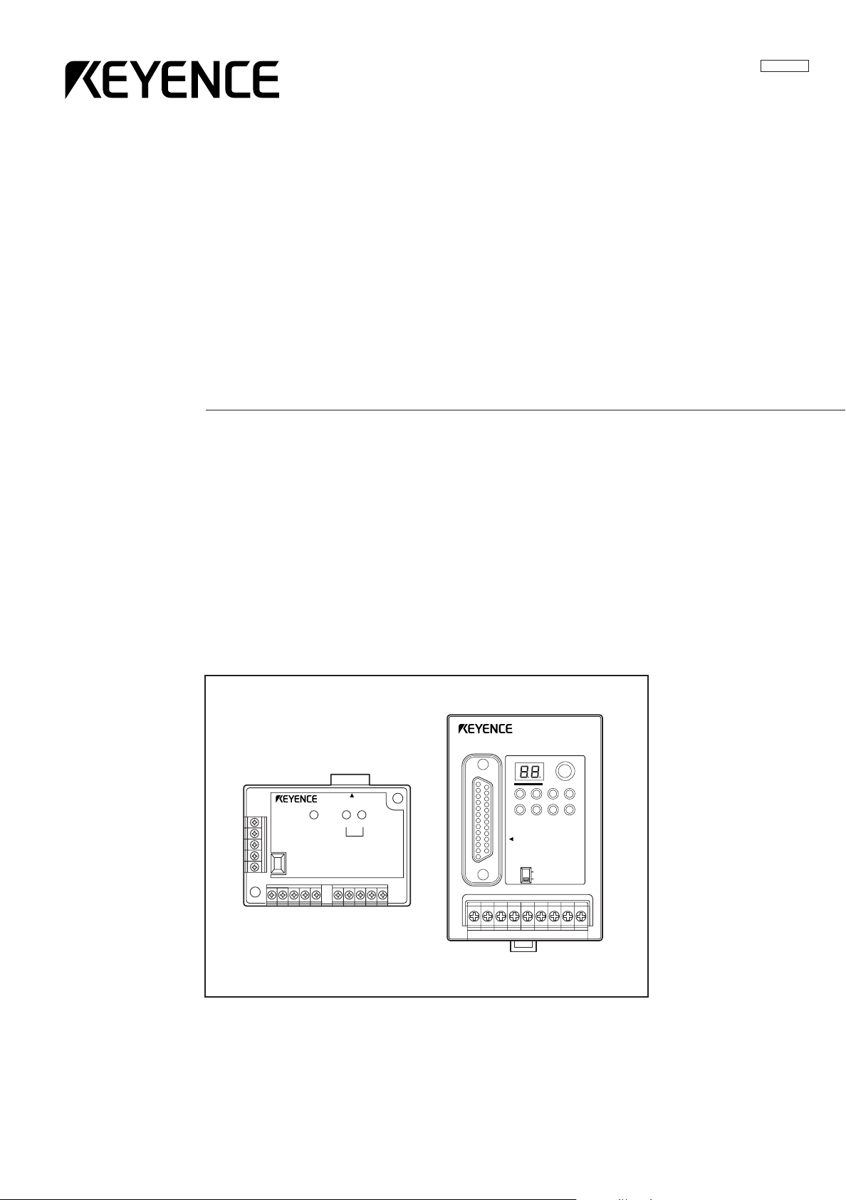
N-400
READER
POWER SD RD
TERMINATOR
ON
OFF
SD RD
POWER TIMING
RS-232C
TERMINATOR
ON
OFF
N-400
TEST
RS-232C
CS RS
SD
RS-455
RD
Page 2

Software License Agreement
Please read this license agreement carefully and be sure you accept its terms
before you use the software. By using the software you signify that you consent to
be bound by the terms and conditions of this agreement.
Keyence grants to you, and you accept a license to use the programs and the
related materials delivered with this agreement.
The manual and the software are copyrighted with all rights reserved. Your rights of
ownership are subject to the limitations and restrictions imposed by copyright laws.
Under the copyright laws, you may not copy the manual or software, in whole or in
part, without the written consent of Keyence, except in the normal use of the
software or to make a backup copy.
It is illegal to copy, reproduce, or transmit any part of the manual or the software in
any form or by any means (including translation to another language, computer
language, or format)except as permitted by the Copyright law. You are permitted to
write the contents of the software into the machine memory of your computer so
that the software can be executed. The software may be associated with one
computer and may be used by more than one person on that computer, or may be
associated with one person and used by that person on more than one computer.
However, in no event shall two or more persons use the software at the same time.
You may not rent or lease the software, but you transfer the software and accompanying written materials on a permanent basis provided you retain no copies and
the recipient agrees to the terms of this agreement. You may not reverse engineer,
decompile, or disassemble the software.
Keyence warrants that if you discover physical defects in the media on which this
software is distributed, or in the manual distributed with the software, Keyence will
replace the media or manual at no charge to you, provided you return the defective
items, postage prepaid and with proof of purchase, within ninety days of the date of
purchase. Keyence reserves the right to revise this software and manual without
obligation to notify any person of such revision. In no event will Keyence be liable
for loss of profits or goodwill or other indirect, special, incidental, or consequential
damages resulting from any defect in the software, media, or manual. Keyence’s
liability for damages to you or others will in no event exceed the total amount paid
by you for the software. In particular, Keyence shall have no liability for any data
stored in or used with Keyence’s products, including the costs of recovering such
data.
MS Windows, Windows 95 are registered trademarks of Microsoft Corporation. All
other company, product names in this publication are registered trademarks of their
respective owners.
i
Page 3
Safety Precautions
This instruction manual describes the operation and function of the N-400. Read
this manual carefully to ensure safe use and maximum performance from your N-
400.
The N-400 can be connected to the BL-700, BL-180 and BL-500 series.
Symbols
The following symbols alert you to important messages. Be sure to read these
messages carefully.
General Precautions
WARNING
CAUTION
Note:
• At startup and during operation, be sure to monitor the functions and performance of the N-400.
•We recommend that you take substantial safety measures to avoid any damage
in the event a problem occurs.
• Do not open or modify the N-400 or use it in any way other than described in
the specifications.
•When the N-400 is used in combination with other instruments, functions and
performance may be degraded, depending on operating conditions and the
surrounding environment.
Failure to follow instruction may lead to injury. (electric
shock, burn, etc.)
Failure to follow instructions may lead to product damage.
Provides additional information on proper operation.
• Do not use the N-400 for the purpose of protecting the human body.
Warnings and Cautions Specific to the N-400
CAUTION
• To operate the N-400/N-48, use a 24 VDC power supply.
Using a different type of power supply may damage the unit.
• This unit is a precision instrument and may be damaged if dropped. Be
careful when carrying and mounting the unit.
• To install this unit, read “Chapter 2, 2.6 Mounting Procedure” in this manual
thoroughly for instructions on proper mounting conditions.
• For the RS-485 connections, use the recommended cable and follow the
instructions given in this manual. (
or “Chapter 2, 2.4.5 Connecting RS-485”.
following these instructions may cause a communication error.
➮
See “Chapter 2, 2.3.3 Connecting RS-485”
) Connecting the RS-485 cable without
ii
Page 4

List of Package Contents
The N-400 includes the following equipment and accessories. Before using the
unit, ensure that all of these items are included with your N-400.
■ N-400 package contents
• N-400 (x 1)
• User’s Manual (x 1)
• N-400 setup software (x 1)
■ N-48 package contents
• N-48 (x 1)
• Instruction manual (x 1)
■ BL-U1 1. package contents
• BL-U1 (x 1)
■ BL-U2 package contents
• BL-U2 (x 1)
1. BL-U1 is not available in Europe. Use BL-U2 instead.
iii
Page 5

Contents
Chapter 1 Overview of the N-400
Chapter 2 Installation Procedure
1.1 Functions of the N-400 ..........................................................................2
1.2 System Configuration ............................................................................4
1.3 Part Names .............................................................................................5
2.1 Installing the N-400 ..............................................................................10
2.2 Connecting N-400 and Wiring .............................................................12
2.2.1 Terminals of I/O terminal block and wiring..............................................12
2.2.2 Connecting RS-232C..............................................................................13
2.3 Connecting N-48 and Wiring ...............................................................16
2.3.1 Connecting the BL series........................................................................16
2.3.2 Terminals of I/O terminal block and connection......................................16
2.3.3 Connecting RS-485.................................................................................19
2.4 Connecting BL-U1 and Wiring ............................................................21
2.4.1 Connecting power supply........................................................................21
2.4.2 Connecting BL series..............................................................................21
2.4.3 Setting BL-U1 DIP switches....................................................................22
2.4.4 Terminals of I/O terminal block and wiring..............................................23
2.4.5 Connecting RS-485.................................................................................25
2.5 Using Connection Test Mode .............................................................26
2.6 Mounting Procedure ............................................................................27
2.6.1 Precautions for mounting environment ...................................................27
2.6.2 Mounting N-400 ......................................................................................28
2.6.3 Mounting N-48 ........................................................................................28
2.6.4 Mounting BL-U1......................................................................................29
Chapter 3 N-400 Setup Procedure
3.1 Installing Setup Software ....................................................................32
3.2 Setup Software Operating Procedure ................................................34
3.2.1 Operating procedure...............................................................................34
3.2.2 Description on each setup screen...........................................................35
3.2.3 Outline of operation.................................................................................36
3.3 Details of Operating Procedure .........................................................38
3.3.1 Setting procedure....................................................................................38
3.3.2 Reading/Saving/Printing File...................................................................44
3.4 Sending/Receiving Settings ................................................................48
3.5 Using Terminal .....................................................................................52
3.6 List of Error Messages ........................................................................55
iv
Page 6

Chapter 4 Multi-Drop Link Mode Control Procedure
4.1 Multi-Drop Link Mode ..........................................................................58
4.1.1 Controlling multi-drop link mode .............................................................58
4.1.2 Setup procedure .....................................................................................60
4.2 Data Communication in Multi-Drop Link Mode .................................61
4.2.1 Auto polling .............................................................................................61
4.2.2 Manual polling.........................................................................................62
4.2.3 Capacity of Transmission Buffer.............................................................63
4.2.4 Handshaking protocol .............................................................................65
4.3 Command Transmission To BL Series ..............................................66
4.4 N-400 Direct Control Commands ........................................................69
4.4.1 Communication procedure......................................................................69
4.4.2 Description of commands .......................................................................70
4.5 N-400 Setup Command ........................................................................75
4.6 Communication Time Consideration ..................................................83
Chapter 5 Multi-Head Mode Control Procedure
5.1 Multi-head Mode ...................................................................................88
5.1.1 Controlling multi-head mode...................................................................88
5.1.2 Setup procedure .....................................................................................89
5.2 Reading Operation in Multi-Head Mode .............................................91
5.2.1 Difference in operation depending on reading mode..............................91
5.2.2 Trigger input signal type..........................................................................93
5.2.3 Data transmission timing.........................................................................94
5.3 Data Communication in Multi-Head Mode .........................................95
5.3.1 Communication format............................................................................95
5.3.2 Handshaking protocol .............................................................................95
5.3.3 Read error code......................................................................................95
5.4 Command Communication in Multi-Head Mode ...............................96
5.4.1 Sending a command to BL series...........................................................96
5.4.2 N-400 direct control/setup commands ....................................................96
5.5 Interference Suppression Function ...................................................97
5.6 Communication Time ..........................................................................98
v
Page 7

Chapter 6 PLC Link
6.1 PLC Link .............................................................................................102
6.1.1 List of PLCs used for PLC link ..............................................................102
6.1.2 Devices used for PLC link.....................................................................103
6.2 Setup Procedure ................................................................................104
6.2.1 Setting the BL Series ............................................................................104
6.2.2 Setting the N-400..................................................................................105
6.2.3 Setting the PLC.....................................................................................106
6.3 Device Assignment ............................................................................108
6.3.1 Device assignment in multi-drop link mode ..........................................108
6.3.2 Device assignment in multi-head scan mode .......................................113
6.4 PLC Link Error ....................................................................................116
Appendices
Appendix A Specifications .....................................................................120
Appendix B Dimensions .........................................................................122
Appendix C Sample Programs ...............................................................124
Appendix D Troubleshooting .................................................................131
Appendix E Indications on the N-400 ....................................................133
Appendix F ASCII Code Table ................................................................134
Appendix G Checksum Calculation Method .........................................135
Appendix H Setup Parameter List ..........................................................137
Appendix I Default Setting List .............................................................139
Appendix J Sample Printout of Setting List .........................................140
Sample programs for multi-drop link......................................124
Sample program for PLC link ................................................126
WARRANTIES
WARRANTIES AND DISCLAIMERS ............................................................141
vi
Page 8

vii
Page 9

Chapter 1
Overview of the N-400
1.1 Functions of the N-400 .........................................................2
1.2 System Configuration ..........................................................4
1.3 Part Names ............................................................................5
Page 10
Chapter 1 Overview of The N-400
1.1 Functions of the N-400
The N-400 multi-drop controller allows the following functions to be added to the BL
series.
1
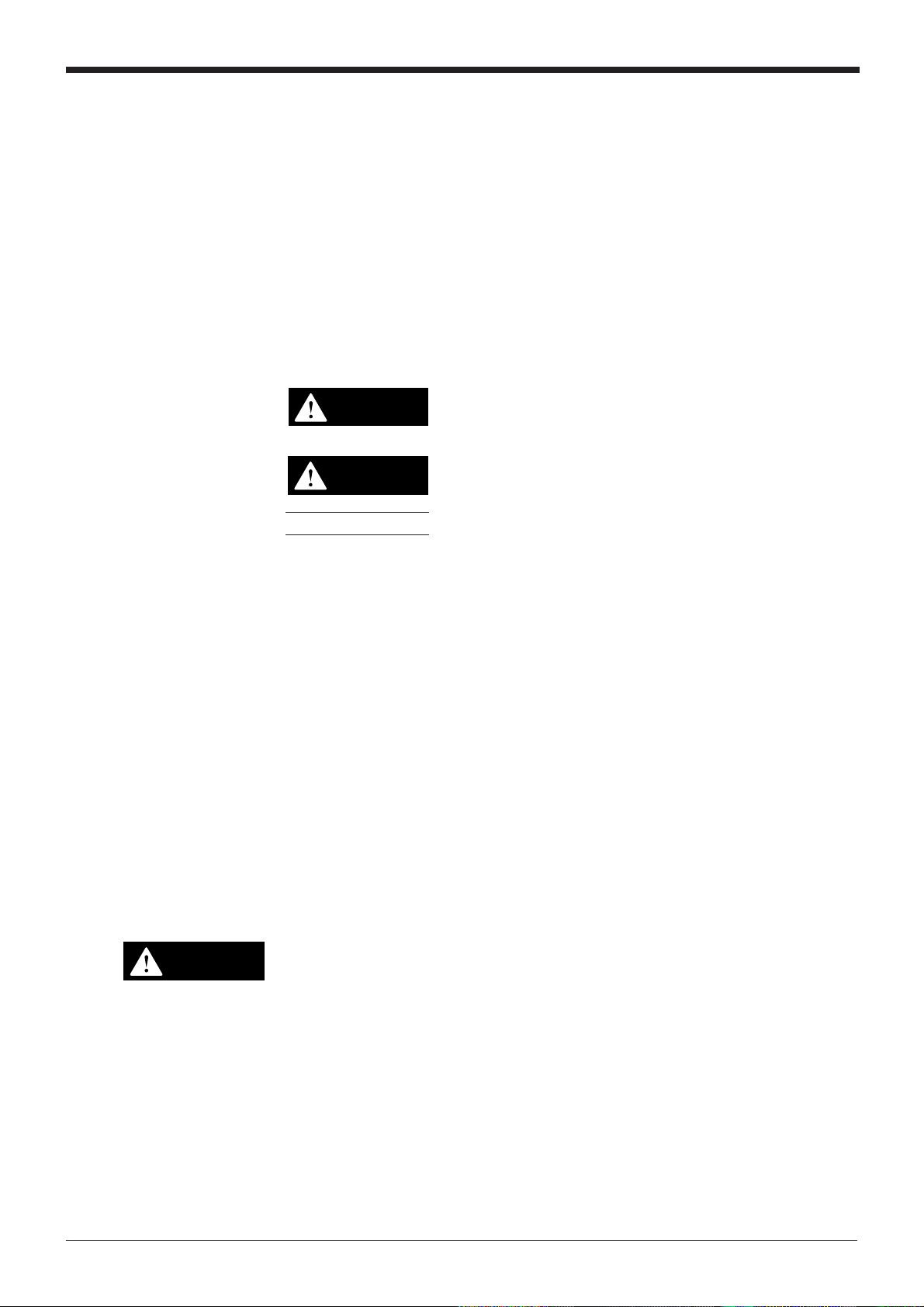
Multi-drop link function (mode)
Note: The BL-U1 and N-48 can be used as an RS-232C to RS-485 converter.
However, the BL-U1 is not available in Europe.
The N-400 can control up to thirty-one BL series units using a host computer,
enabling the multi-drop link configuration.
The communication path is an RS-485 cable, which provides high noise-resistance
and enables data transmission over a long distance (up to 1.2 km). Since a twisted
pair cable (two cables) is used for the connections, the multi-drop link configuration
can be realized with simple wiring.
The N-400 controls the complicated communication (RS-485 communication)
between each BL series and the N-400. Since the host computer works only for
communication with the N-400, it can be operated with a simple program. (The ID
number assigned to the head of the transmitted data allows you to identify the BL
series unit that sends the data.) Therefore, the host computer’s job is reduced with
this system configuration.
BL series
N-400
RS-232C
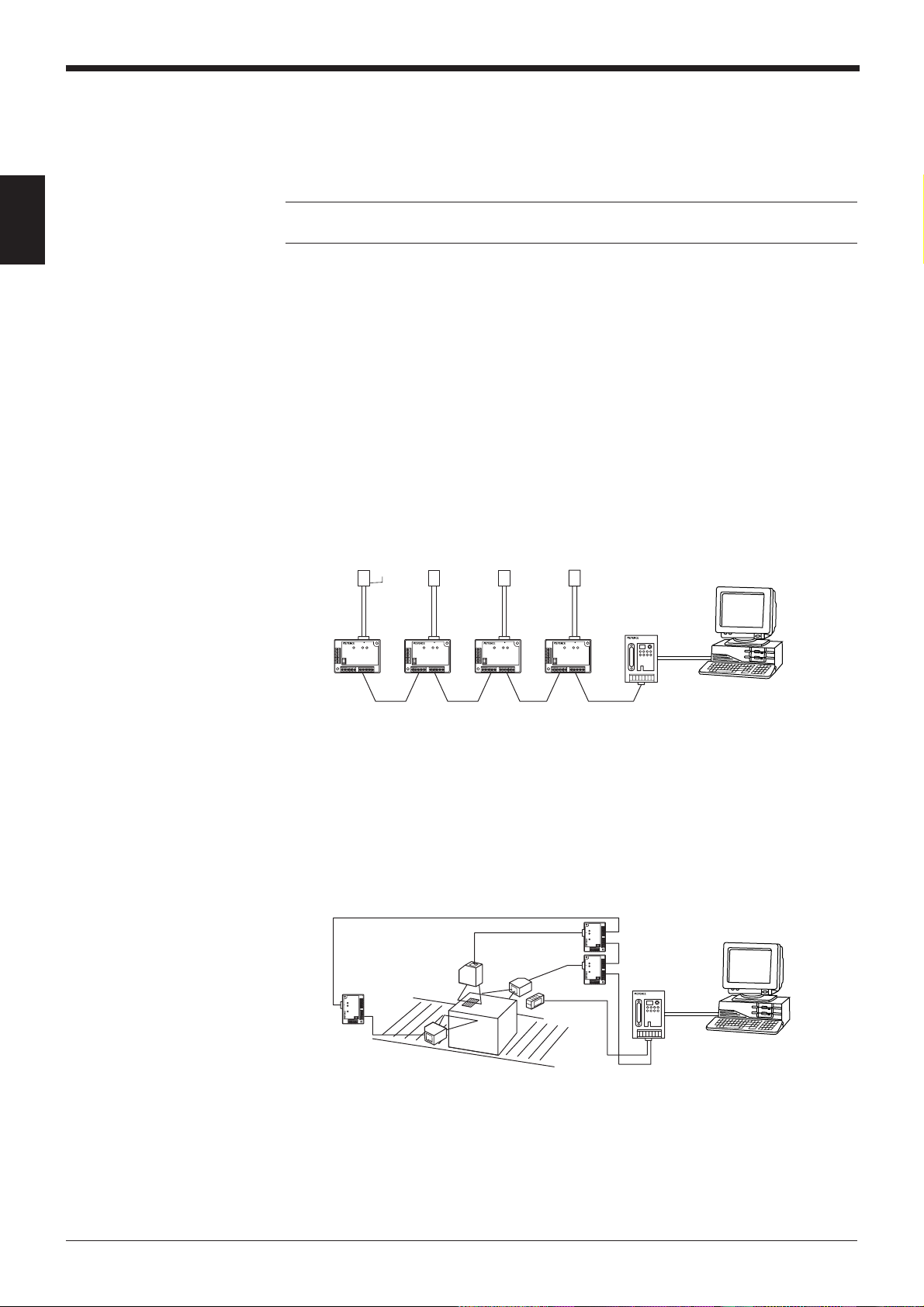
Multi-head scan function (mode)
If the position of bar codes is unknown in a product, or bar codes are printed in
several positions, the bar codes cannot be read with a single bar code reader. In
such cases, several bar code readers need to be mounted in various positions or at
various angles.
When the N-400 controller is used in multi-head scan mode, a host computer can
control several BL series units as if they were a single unit.
N-48
or
BL-U1
N-48
or
BL-U1
*
BL series
Sensor for
trigger input
RS-485
N-400
RS-485
*
RS-232C
Host
Host
2
Page 11
Chapter 1 Overview of The N-400
■ Mutual-interference suppression function (in multi-head scan mode)
When several bar code readers are mounted close to each other, for example when
reading multi-stage labels as shown below, the units’ light sources (laser beams)
interfere with each other, affecting the reading stability.
The mutual-interference suppression function allows the BL series’ laser beams to
turn ON sequentially, thus suppressing the mutual interference to ensure stable
readings.
Since the laser beams turn ON sequentially, the duration of laser OFF time (when
each unit is not reading a bar code) becomes longer as the number of connected
units is increased. Therefore, the bar code readers may fail to read bar codes if the
line speed is set too fast.
BL series
N-400
N-48
or
BL-U1
Sensor for
trigger input
RS-232C
Host
1
RS-485
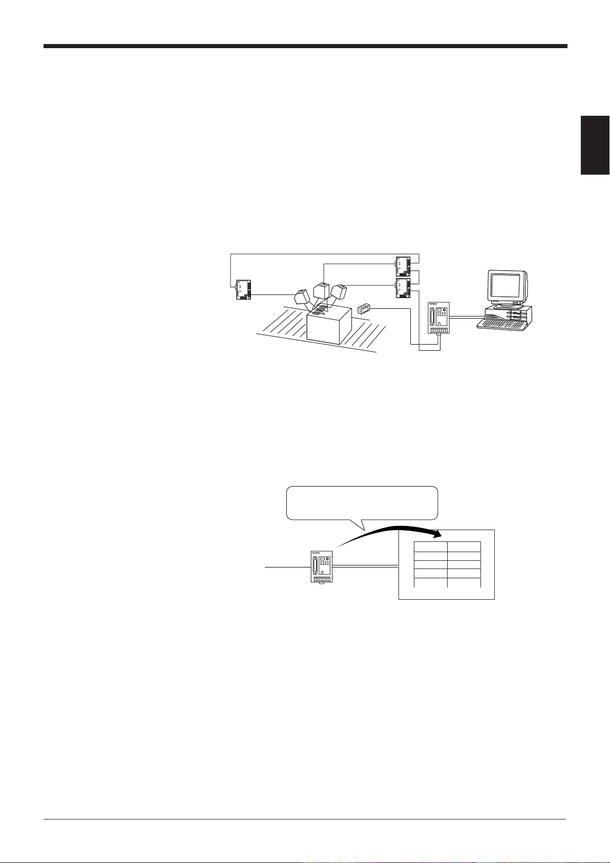
■ PLC link function
In the multi-drop link mode or multi-head scan mode, the PLC link function enables
the BL series’ data to be sent to a PLC without a communication program. Using
this function, you can reduce the number of steps for a PLC program.
No communication program is necessary,
because the N-400 stores the data read by
the BL series directly into the PLCs memory.
N-400
To BL
DM103
DM104
DM105
DM106
•
•
•
4
&30
&31
&32
•
•
•
3
Page 12
Chapter 1 Overview of The N-400
N-400
RS-232C
RS-485
Host
Sensor for
trigger input
BL series
*
*
N-48
or
BL-U1
N-400 setup
software
for Windows
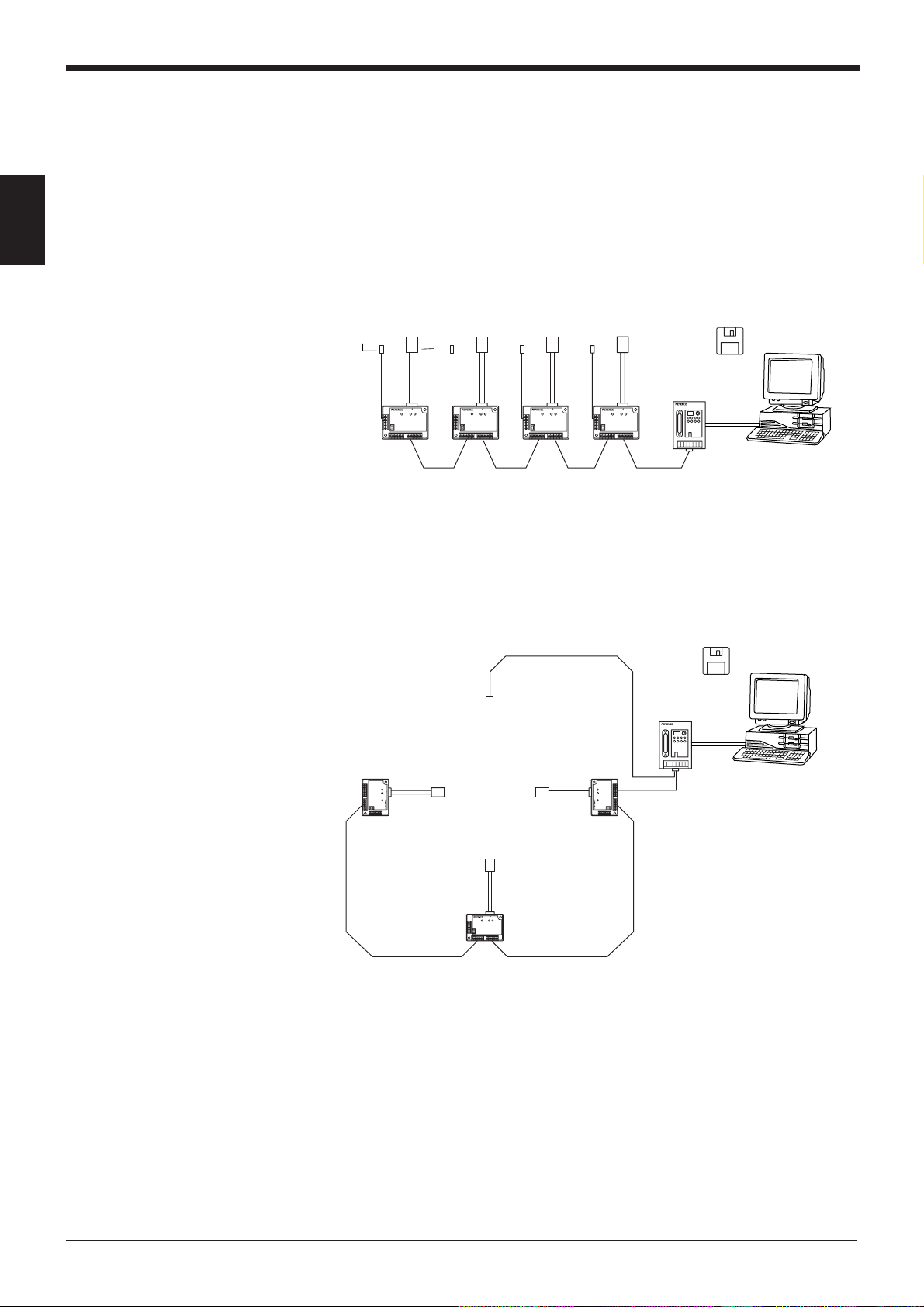
1.2 System Configuration
The system configurations using the N-400 controller are as follows:
This section describes multi-drop link mode and multi-head scan mode individually.
1
Multi-drop link mode
• Maximum number of connectable units: 31
• Maximum extension distance: 1.2 km
* The N-400 can be connected to the BL-700/BL-500/BL-180 series bar code
* Additional 24 VDC power supply is required for the N-400 and N-48.
readers.
Multi-head scan mode (with the interference suppression function)
• Maximum number of connectable units: 31
• Maximum extension distance: 1.2 km
Sensor for
trigger input
N-48
or
BL-U1
* Connect the sensor for trigger input to the N-400.
* The N-400 can be connected to the BL-700/BL-500/BL-180 series bar code
readers.
* Additional 24 VDC power supply is required for the N-400 and N-48.
N-400
RS-485
RS-232C
*
N-400 setup
software
for Windows
Host
4
Page 13
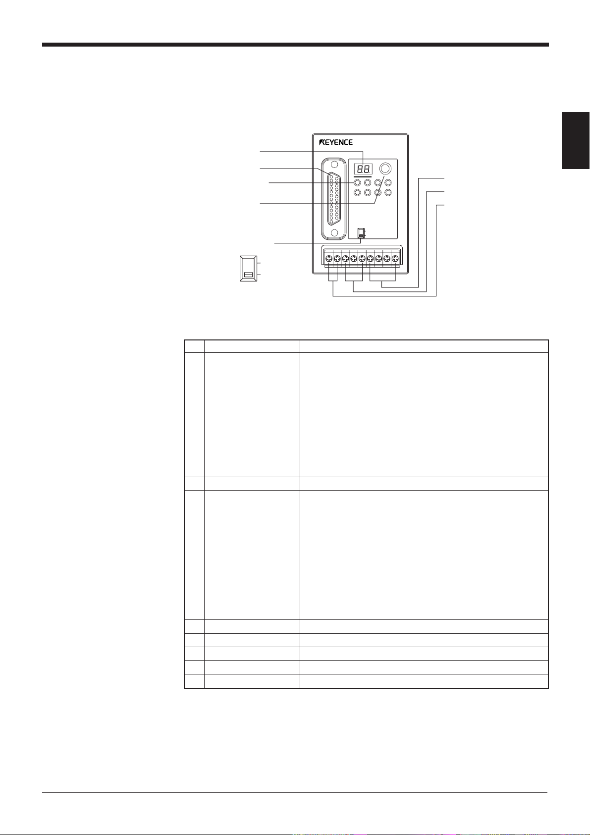
1.3 Part Names
N-400
Chapter 1 Overview of The N-400
SD RD
POWER TIMING
TERMINATOR
ON
OFF
N-400
TEST
RS-232C
CS RS
SD
RS-455
6 Power supply terminal
RD
7 RS-485 terminal
8 Trigger input terminal
1 Display LEDs
2 RS-232C port
3 Communication
status indicator LEDs
4 Test switch
5 Terminator switch
ON
OFF
No. Name Function
1 Display LEDs • Normally displays “00” (ID number of the N400).
• Displays the ID number of the device being tested.
(➮ See p. 26.)
• Displays “S1 (51)” to indicate setup mode.
(➮ See p. 75.)
• Displays “S0 (50)” to indicate initial communication status
after a setting change.
• Displays the N-400’s error condition.
(➮ See p. 48.)
(➮ See 131.)
• Displays the ID number of the device currently connected
when sending a hotline command.
(➮ See p. 73.)
2 RS-232C port • Connect a host computer or PLC to this connector.
3 • POWER: Lit when power is ON.
Communication
status indicator LEDs
• TIMING: Lit when the trigger input connected to the N-400
is ON.
(For the RS-232C connections)
Lit when the SD, RD, RS and CS signals are ON.
(For the RS-485 connections)
SD: Lit when the N-400 is sending data.
RD: Lit when the N-400 is receiving data.
* Both the SD and RD indicators are lit when the N-400 is
receiving data.
4 Test switch Starts the connection test mode.
5 Terminator switch Switches the terminator’s ON/OFF status.
6 Power supply terminal Connect a 24 VDC power supply.
7 RS-485 terminal Used for the multi-drop link connection.
8 Trigger input terminal Used for trigger input in multi-head scan mode.
1
5
Page 14
Chapter 1 Overview of The N-400
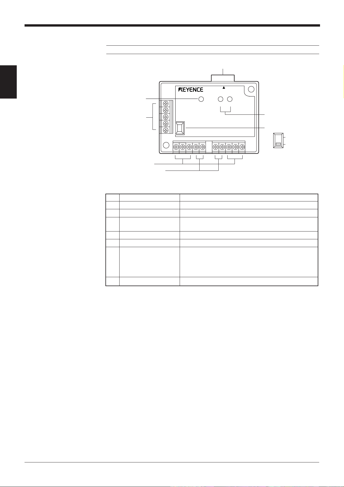
N-48
1
Note: BL-U1 is not available in the Europe area.
1 READER port
READER
2 POWER LED
POWER SD RD
3 I/O terminals
4 RS-485 terminals
5 Power supply terminals
6 Communication
status indicator
LEDs
7 Terminator switch
ON
OFF
No. Name Function
1 READER port Connect the BL series to this port.
2 POWER LED Lit when power is ON.
3 I/O terminals Includes the trigger input terminal and OK/NG output
terminals.
4 RS-485 terminals Used for multi-drop link mode.
Power supply terminals
5 Connect a 24 VDC power supply to these terminals.
6 Allows you to monitor the communication status of the
Communication status
indicator LEDs
7 Terminator switch Turns the terminator ON/OFF.
READER port.
SD: Lit when the BL series is sending data.
RD: Lit when the BL series is receiving a command.
6
Page 15
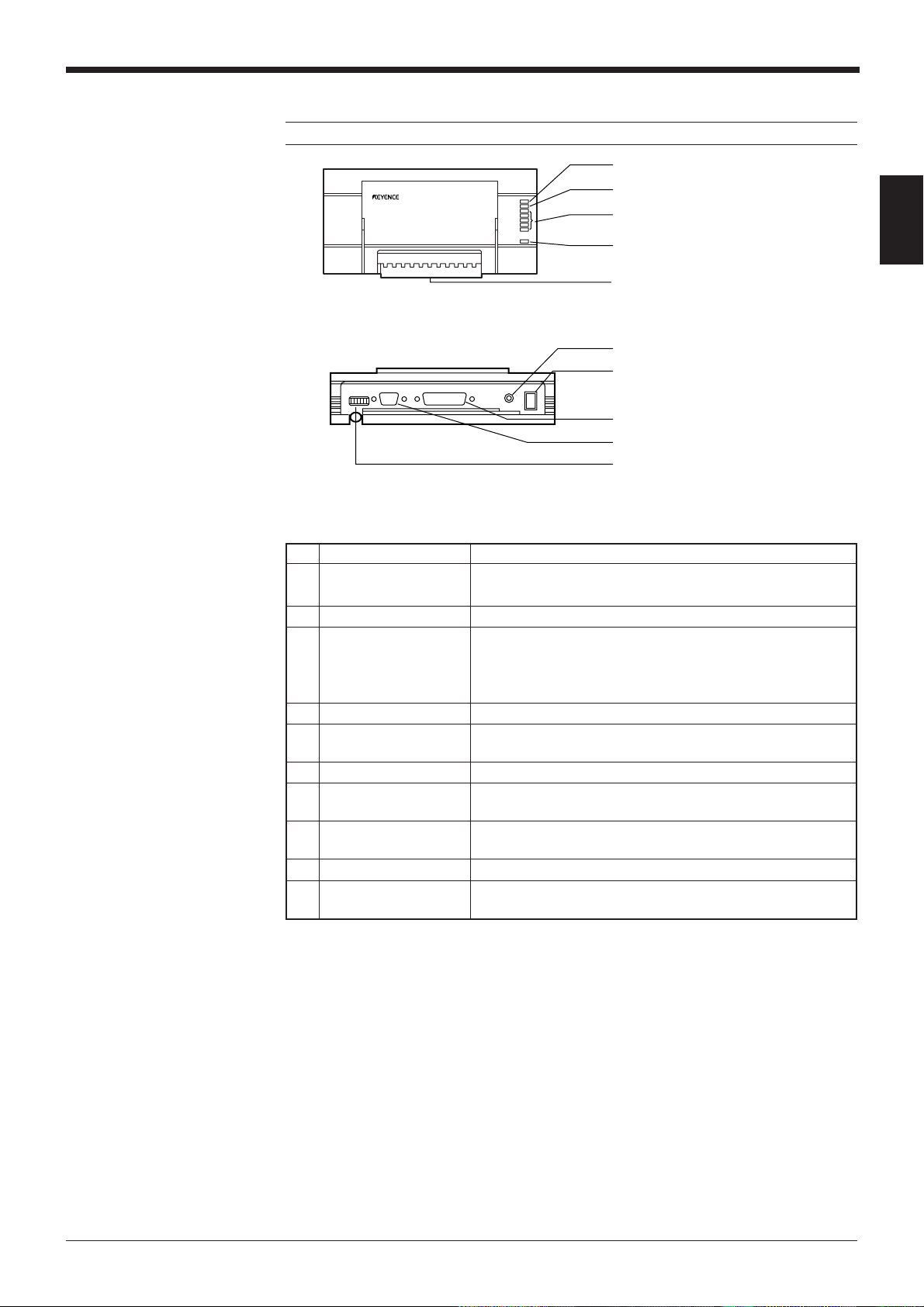
BL-U1
Note: The BL-U1 is not available in Europe
Chapter 1 Overview of The N-400
1 OK/NG LED
2 TIMING LED
3 Communication status indicator
LEDs
4 POWER LED
5 I/O terminal block
6 Power switch
7 Power supply cable (2 m)
8 RS-232C port
9 READER port
0 DIP switches
1
No. Name Function
1 OK/NG LED • When OK output is ON: The green LED lights.
• When NG output is ON: The red LED lights.
2 TIMING LED Lit when trigger input is ON.
3 • Allows you to monitor the communication status of the RS-
Communication status
indicator LEDs
4 POWER LED Lit when power is ON.
5 I/O terminal block Includes the trigger input terminal, OK/NG output terminals,
6 Power switch Turns the power ON/OFF.
Power supply cable
7 Use a 100 to 240 VAC (50/60 Hz) power supply.
(2 m)
8 RS-232C port Connect a personal computer to this port. This port is
9 READER port Connect the BL series to this port.
0 DIP switche Switches the communication port, and turns the terminator
232C port.
• The SD, RD, RS and CS indicators are provided in this
order from the top.
RS-422A terminal and RS-485 terminal.
unused in multi-drop link mode.
ON/OFF.
7
Page 16

Chapter 1 Overview of The N-400
1
8
Page 17

Chapter 2
Installation Procedure
2.1 Installing the N-400 .............................................................10
2.2 Connecting N-400 and Wiring ............................................12
2.2.1 Terminals of I/O terminal block and wiring.............................12
2.2.2 Connecting RS-232C.............................................................13
2.3 Connecting N-48 and Wiring ..............................................16
2.3.1 Connecting the BL series.......................................................16
2.3.2 Terminals of I/O terminal block and connection.....................16
2.3.3 Connecting RS-485 ...............................................................19
2.4 Connecting BL-U1 and Wiring ...........................................21
2.4.1 Connecting power supply ......................................................21
2.4.2 Connecting BL series.............................................................21
2.4.3 Setting BL-U1 DIP switches...................................................22
2.4.4 Terminals of I/O terminal block and wiring.............................23
2.4.5 Connecting RS-485 ...............................................................25
2.5 Using Connection Test Mode ............................................26
2.6 Mounting Procedure ...........................................................27
2.6.1 Precautions for mounting environment ..................................27
2.6.2 Mounting N-400 .....................................................................28
2.6.3 Mounting N-48 .......................................................................28
2.6.4 Mounting BL-U1.....................................................................29
Page 18

Chapter 2 Installation Procedure
2.1 Installing the N-400
2
■ Equipment used
• N-400 multi-drop controller
• BL series bar code readers
The N-400 can be connected to the BL-700, BL-500 and BL-180 series bar
code readers.
• N-48 (or BL-U1) power supply unit for BL series (RS-485 mode)
Each bar code reader requires one N-48 (or BL-U1) power supply.
• BL-U2 (or BL-U1) power supply unit for BL series (RS-232C mode)
To change the BL series’ settings, one BL-U2 or BL-U1 power supply unit is
required.
To use the N-48 for multi-drop link, an additional BL-U2 24 VDC power supply
unit is required. (The N-48 does not provide an RS-232C port.)
(The BL-U1 can be used as an RS-232C or RS-485 power supply.)
• RS-232C cable for the N-400
This cable is used to connect the N-400 and the host computer.
Use a cable appropriate for the personal computer and the PLC’s pin assignment. OP-98769 cable and OP-25057 connector are available.
• RS-232C cable for BL series setup
This cable is used to connect the BL-U2 (or BL-U1) and the host computer to
change the BL series’ settings. Since the wiring of this cable is different from
that of the RS-232C cable for the N-400, both cables must be prepared.
For wiring the BL-U2 and BL-U1, see the “BL-U2 Instruction Manual” and “BL
series User’s Manual”, respectively.
OP-27937 cable is available for BL-U2. (OP-22149 cable and OP-25057 are
available for BL-U1.)
• Twisted pair cable for the RS-485
Prepare the recommended cable.
• Host computer
Use a personal computer with an RS-232C port.
When large quantities of data are sent from several BL series, they may exceed
the host computer’s data processing capacity.
If this occurs, reduce the number of the connected BL series units, or enhance
the data processing capacity (including the programming language) of the host
computer.
■ Setup and connection
1) Setting the BL series bar code readers
Prepare the BL series unit, the BL-U2 (or BL-U1) RS-232C power supply unit,
the RS-232C cable used for setup, and a personal computer. Set up the BL
series using the BL series setup software.
For connection and setup procedures, see the “BL series User’s Manual”.
For the pin assignment of the connection cable between the BL-U2 and the host
computer, see the “BL-U2 Instruction Manual”.
(➮ See pp. 19, 20 and 25.)
10
The setting contents vary slightly depending on the mode being used. Refer to
the following pages for more information.
• Multi-drop link mode: p. 60
• Multi-head scan mode: p. 87
Page 19

Chapter 2 Installation Procedure
2) Setting the N-400
Prepare the N-400, the RS-232C cable for the N-400, and a personal computer.
Set up the N-400 using the N-400 setup software.
For the setup software operating procedure, see pp. 32 and following.
The setting contents vary slightly depending on the mode being used.
•Multi-drop link mode: p. 60
•Multi-head scan mode: p. 88
• PLC link: p. 102
3) Setting a host computer/PLC
For the RS-232C communication, set the baud rate, data length, parity and stop
bit length according to the settings of the N-400.
To use a PLC link, set up the PLC according to pp. 104 and 105.
4) Connection between the BL series and N-400 (See pp. 19, 20 and 25.)
Connect the N-48 (or BL-U1) power supply unit to the BL series. Then connect
the specified cable (twisted pair cable) between the power supply and the N-
400. Turn ON the equipment terminator at both ends of the connection.
When using the BL-U1, set the DIP switch to “RS-485”. (See p. 22.)
5) Connection between the N-400 and host computer/PLC (See pp. 13 to 15.)
To connect the N-400 to the host computer or PLC, use the RS-232C cable
whose pin assignment conforms to that of the host computer and PLC.
6) Checking the RS-485 connection between the N-400 and the BL series
The N-400 provides a connection test mode that checks whether the RS-485
connection is correct or not. Using this function, check whether the RS-485
communication can be correctly performed.
For the procedure for using this function, see p. 26.
7) Connecting a sensor for trigger input
Connect a sensor for trigger input to each N-48 or BL-U1 unit. (This sensor is
not required when controlling the BL series’ reading operation using the read
start/end commands.)
2
To use the BL series in multi-head scan mode, connect a sensor for trigger input
to the N-400. (This sensor is not required when controlling the BL series’ reading operation using the read start/end commands.)
If the sensor for trigger input is directly connected to each BL series, the BL
series cannot operate normally.
8) Checking operation
Using the terminal software included in the N-400 setup software, check
whether the RS-232C communication between the N-400 and host computer
can be performed correctly. (See p. 52.)
To use a PLC link, check whether data is stored in the PLC’s memory.
11
Page 20
Chapter 2 Installation Procedure
2.2 Connecting N-400 and Wiring
This section describes the procedure for connecting the N-400 to external equipment.
TIM
COM
2
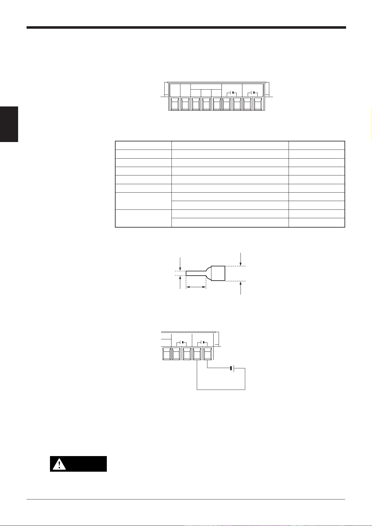
2.2.1 Terminals of I/O terminal block and wiring
Symbol Description Signal direction
TIM Trigger input Input
COM Common terminal for trigger input Input
RS-485 SG RS-485 signal ground –––
RS-485 + RS-485 + terminal Input/Output
RS-485 - RS-485 - terminal Input/Output
24 VDC OUT 24 VDC power output + terminal Output
24 VDC power output - terminal Output
24 VDC IN 24 VDC power input + terminal Input
24 VDC power input - terminal Input
* Viewed from the left of the terminal block.
• The following I-type clips can be used for the connections.
SG
RS-485
+-
24V DC IN
+–
24V DC IN
+–
Connecting power supply
2.0 mm
max.
6 mm min
5 mm max.
The N-400 operates with a 24 VDC power supply.
24V DC IN
+–
–
24V DC IN
+–
24 VDC
+
When a 24 VDC power supply is connected to the power supply “IN” terminal, the
“OUT” terminal can be used as the 24 VDC power supply output terminal. (Note:
The power supply connected to the “IN” terminal must have a capacity high enough
to supply power to the equipment connected to the “OUT” terminal.)
Using this function, the “OUT” terminal can be used as a 24 VDC power supply for
each BL series connected in the multi-drop link configuration. (For a connection
example, see p. 19.)
12
CAUTION
To operate the N-400, be sure to use a 24 VDC power supply. Using a power
supply exceeding 24 VDC or using an AC power supply may damage the unit.
If your system must comply with UL regulations, be sure to use the power
supply with NEC class 2 output.
Page 21
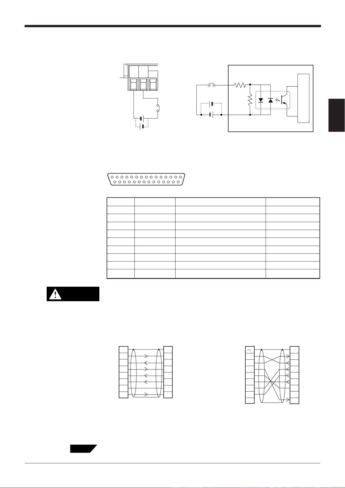
Connecting trigger input
To use multi-head scan mode, connect the trigger input to the N-400 only, instead
of to each BL series unit.
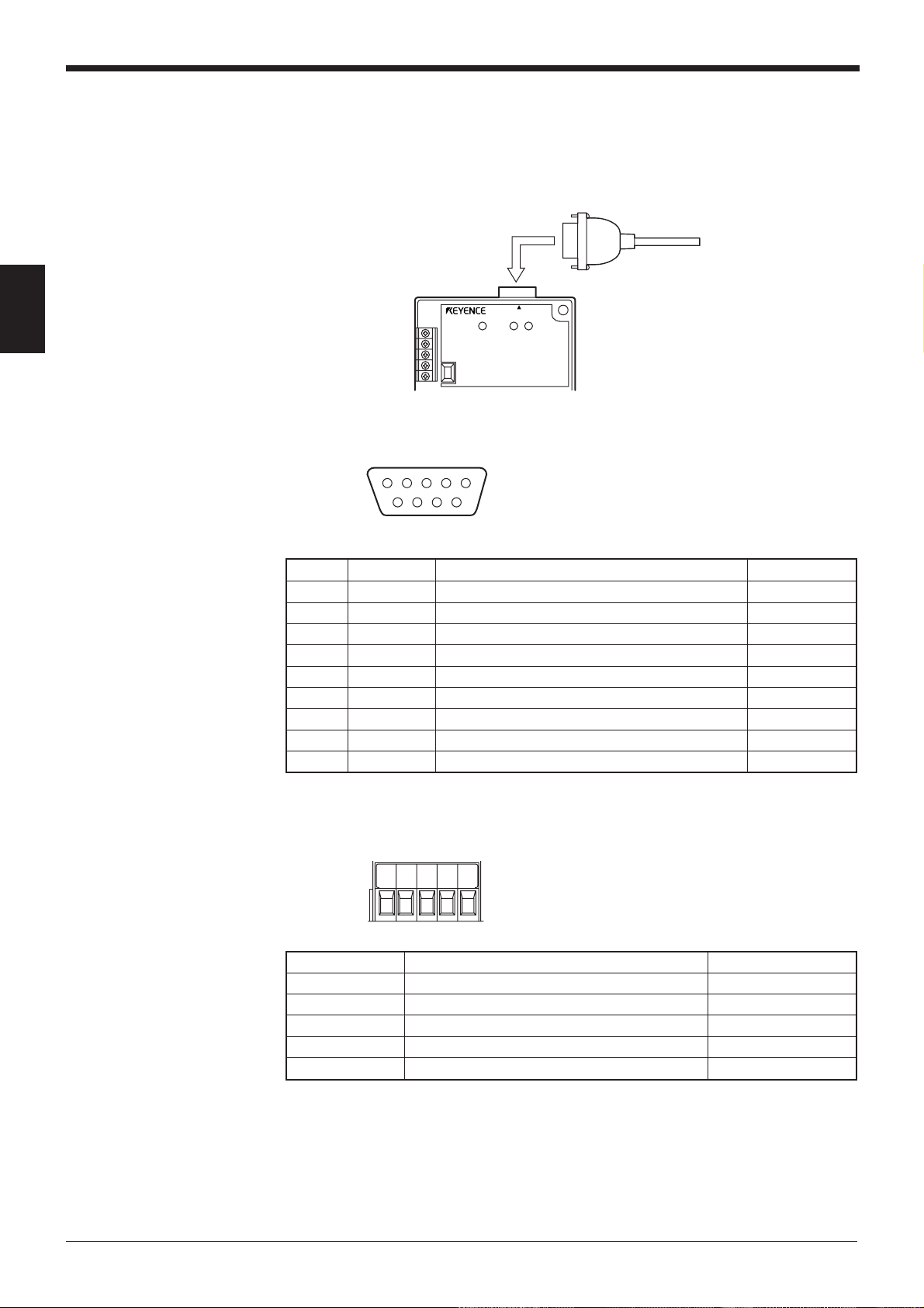
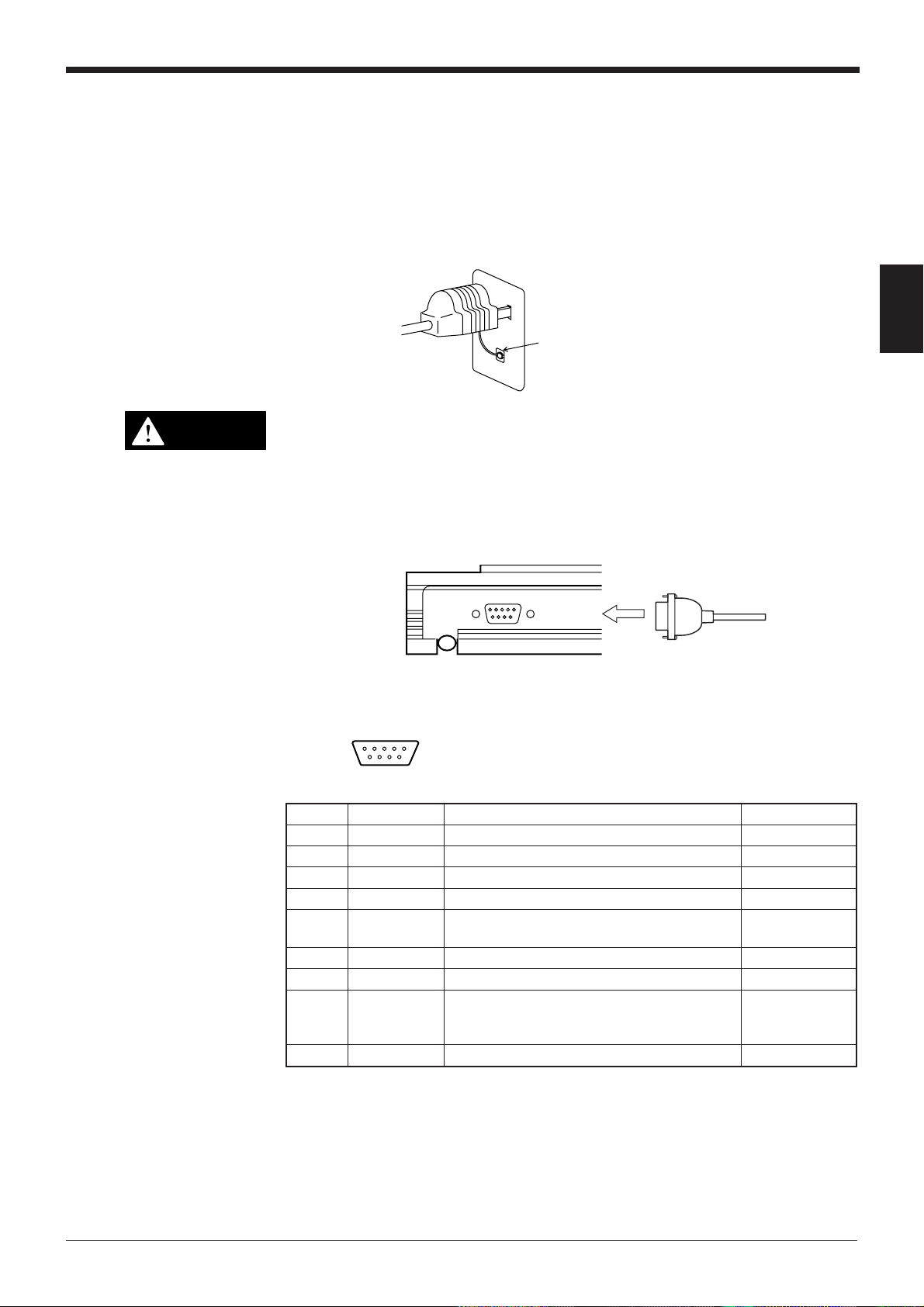
2.2.2 Connecting RS-232C
TIMSGCOM
+
+
15 to 26 VDC
Contact
or solid state
Chapter 2 Installation Procedure
TIM
+
Internal circuit
+
COM
2
Pin assignment
CAUTION
RS-232C cable connections
Tips
13 1
D-sub 25-pin (male)
DCE specification (defined as terminal)
25 14
M2.6 screw
Pin No. Symbol Function Signal direction
1FG Frame ground —
2 SD (TXD) Sends data. Input
3 RD (RXD) Receives data. Output
4 RS (RTS) Ready to send data. Input
5 CS (CTS) Request to send data. Output
6 DR (DSR) Connected to pin No. 20 inside. Output
7SG Signal ground —
20 ER (DTR) Connected to pin No. 6 inside. Input
25 +5 V 5 V power supply output (100 mA) Output
Pin No. 25 is used for a 5 V power supply output. Do not connect this terminal to the ground terminal or any other terminal when it is unused. Doing this
may damage the N-400 or the external device connected to this terminal.
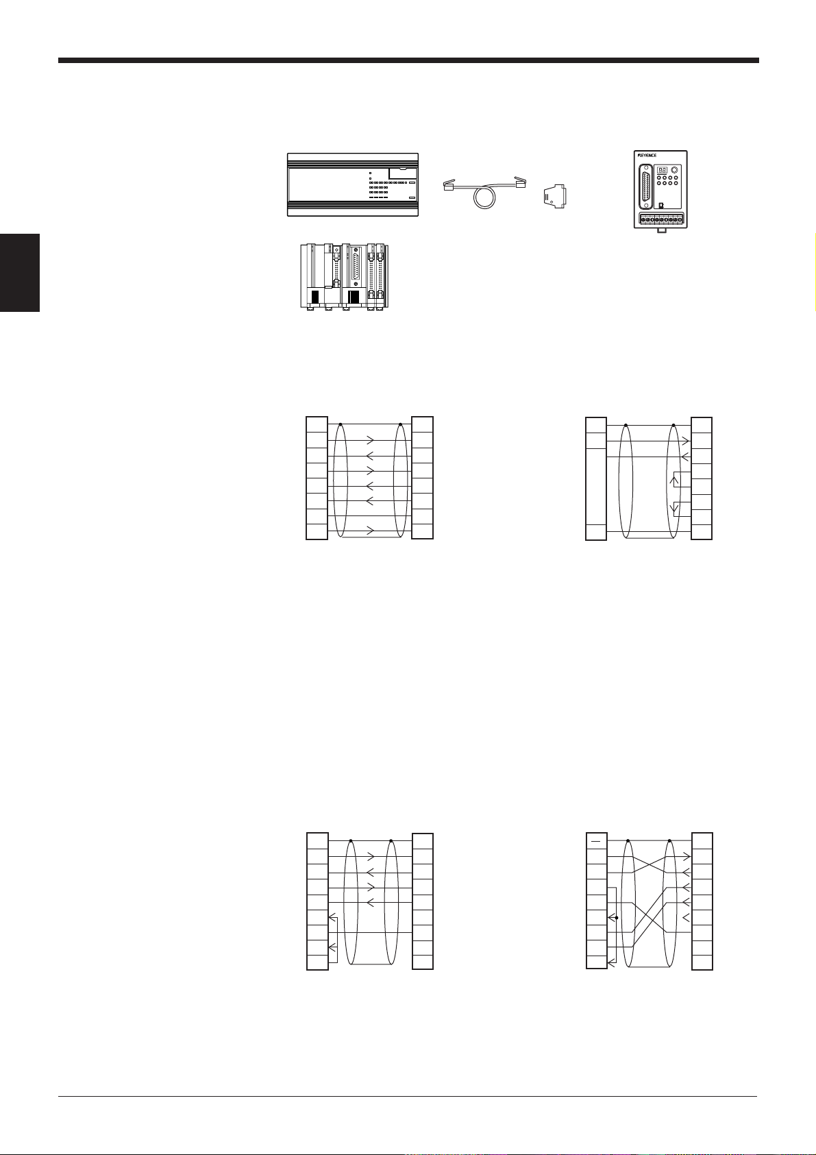
■ Connecting personal computer
• Connecting the computer with 25-pin • Connecting IBM PC
Computer
2
SD
3
RD
4
RS
CS
5
6
DR
SG
7
ER
20
D-sub 25-pin (male)
M2.6 screw
* The OP-98769 cable (1.5 m: manufactured
by KEYENCE) can be used.
N-400
FGFG
11
2
SD
3
RD
4
SG
RS
5
6
CS
DR
7
ER
20
D-sub 25-pin (male)
M2.6 screw
Connector case
RD
SD
ER
SG
DR
RS
CS
CD
D-sub 9-pin (female)
#4-40 screw
* The OP-98769 cable (1.5 m: manu
PC
2
3
4
5
6
7
8
N-400
1
FG
SD
2
RD
3
4
RS
5
CS
6
DR
7
SG
8
201
ER
D-sub 25-pin (male)
M2.6 screw
factured by KEYENCE) and the
OP25057 conversion connector can
be used.
A commercially-available straight cable (D-sub 25 pin - 25 pin, or D-sub 25 pin - 9
pin) can be used.
13
Page 22
Chapter 2 Installation Procedure
2
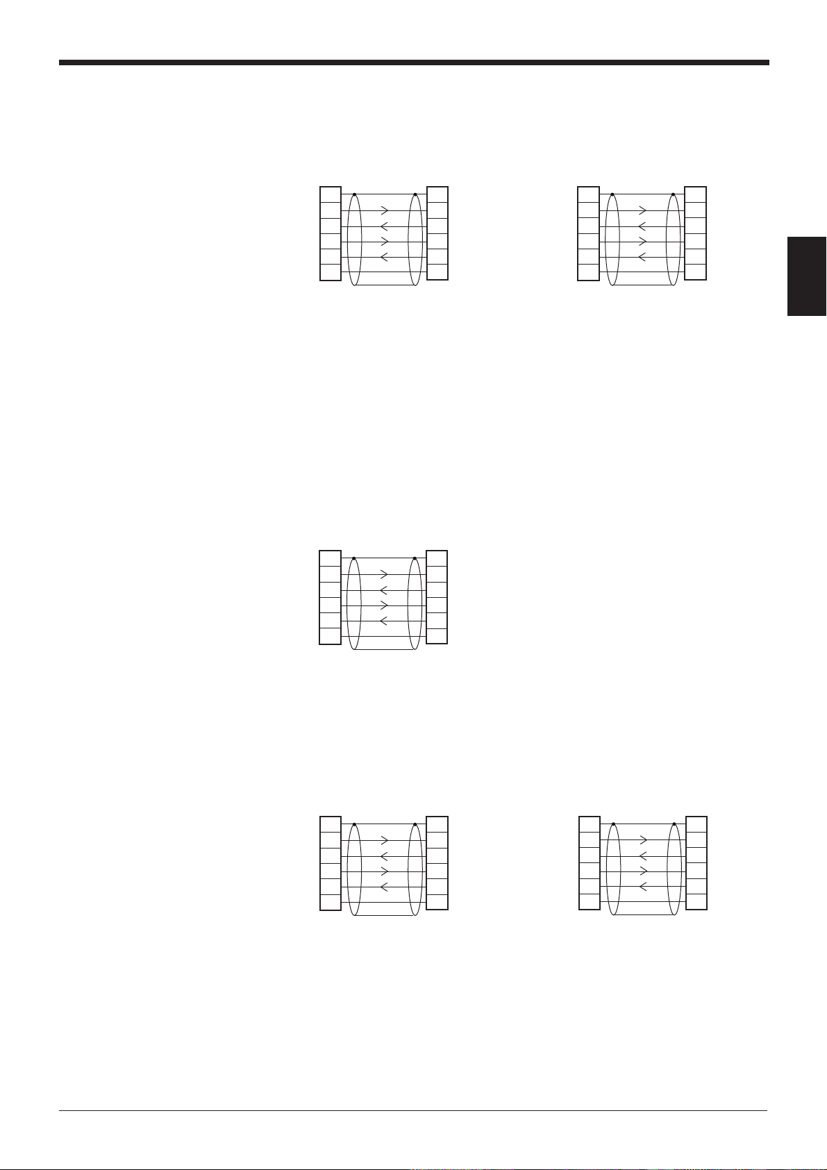
■ Connecting KV series/Handheld programmer port
Use the optional cable manufactured by KEYENCE.
KV-10, 16, 24
KV-40, 80
or
OP-24025 (5 m)
OP-96369OP-24045 (1 m)
POWER TIMING
TERMINATOR
N-400
TEST
RS-232C
CS RS
SD RD
RD
SD
RS-455
ON
OFF
1.
KV-300
■ Connecting KV-L2
1.
1. KV-300 and KV-L2 are not available in Europe.
Port 1 Terminal block
KV-L2
2
SD
3
RD
4
RS
CS
5
6
DR
SG
7
ER
20
D-sub 25-pin (male)
M2.6 screw
* The OP-98769 cable (1.5 m: manufactured
by KEYENCE) or a commercially-available
straight cable can be used.
N-400
FGFG
11
2
SD
3
RD
4
SG
RS
5
6
CS
DR
7
ER
20
D-sub 25-pin (male)
M2.6 screw
KV-L2
5
RD
SG
Terminal block
1. KV-300 and KV-L2 are not available in Europe.
■ Connecting MELSEC-A series
N-400
FGSD
13
2
SD
3
RD
4
RS
CS
5
6
DS
ER
20
SG
71
D-sub 25-pin (male)
M2.6 screw
14
Connection with AJ71C24, AL71C24-S*,
A0J2-C214S1, AJ71UC24
N-400Link unit
FGFG
11
2SD
3
RD
4
RS
CS
5
6
DR
SG
7
CD
8
ER
D-sub 25-pin (male)
M2.6 screw
2
SD
3
RD
4
RS
CS
5
DR
6
SG
7
8
ER
2020
D-sub 25-pin (male)
M2.6 screw
Connection with A1SJ71C24-R2/PRF,
A2CCPUC24, A2CCPUC24-PRF,
A1SJ71UC24-R2/PRF
Connector case
RD
SD
ER
SG
DR
RS
CS
CD
D-sub 25-pin (male)
M2.6 screw
Link unit
2
3
4
5
6
7
8
N-400
1
FG
SD
2
RD
3
4
RS
5
CS
6
DR
7
SG
8
201
ER
D-sub 25-pin (male)
M2.6 screw
Page 23
■ SYSMAC-C series
Connection with C-200H-LK201(-V1),
C-500-LK203, C-500-LK201-V1, C120LK201-V1
Chapter 2 Installation Procedure
Connection with C-20H, C-28H,
C-40H, C-60H, C-80H
Link unit
2
SD
3
RD
4
RS
CS
5
SG
7
D-sub 25-pin (male)
M2.6 screw
N-400
FGFG
11
2
SD
3
RD
4
RS
CS
5
SG
7
D-sub 25-pin (male)
M2.6 screw
* The OP-98769 cable (1.5 m: manufactured by
KEYENCE) or a commercially-available
straight cable can be used.
Connection with C-200HS(CPU21/23/31/
33), CQM1(CPU21/41/42/43/44), C200HE(CPU42), C200HG(CPU43/63),
C200HX(CPU44/64), C200HWCOM02/
COM04/COM05/COM06
SD
RD
RS
CS
SG
PLC
2
3
4
5
9
N-400
11
2
3
4
5
7
FGFG
SD
RD
RS
CS
SG
PLC
2
SD
3
RD
4
RS
CS
5
SG
7
D-sub 25-pin (male)
M2.6 screw
N-400
FGFG
11
2
SD
3
RD
4
RS
CS
5
SG
7
D-sub 25-pin (male)
M2.6 screw
2
D-sub 25-pin (male)
M2.6 screw
D-sub 25-pin (male)
M2.6 screw
■ SYSMAC-CV series
Connection with CV500-LK201(Port 1) Connection with CV500-
LK201(Port 2), CV500, CV1000,
CVM1
Link unit
2
SD
3
RD
4
RS
CS
5
SG
7
D-sub 25-pin (male)
M2.6 screw
N-400
FGFG
11
2
SD
3
RD
4
RS
CS
5
SG
7
D-sub 25-pin (male)
M2.6 screw
* The OP-98769 cable (1.5 m: manufactured by
KEYENCE) or a commercially-available straight
cable can be used.
PLC
2
SD
3
RD
4
RS
CS
5
SG
9
D-sub 25-pin (male)
M2.6 screw
D-sub 25-pin (male)
M2.6 screw
N-400
11
2
3
4
5
7
FGFG
SD
RD
RS
CS
SG
15
Page 24
Chapter 2 Installation Procedure
2.3 Connecting N-48 and Wiring
2.3.1 Connecting the BL series
Connect the BL series to the READER port of the N-48.
2
Pin assignment
N-48
READER
POWER SD RD
12345
D-sub 9-pin (male)
DCE specification (defined as terminal)
#4-40 screw
6789
Pin No. Symbol Function Signal direction
1 TIM Trigger input Output
2 RD (RXD) Receives data. Output
3 SD (TXD) Sends data. Input
4OKOK Input
5 GND (SG) Ground (Common ground for respective signal) —
6NGNG Input
7 RS (RTS) Ready to send data. Input
8 CS (CTS) Request to send data. Output
9 +5 V 5 V power supply output (600mA) Output
BL series
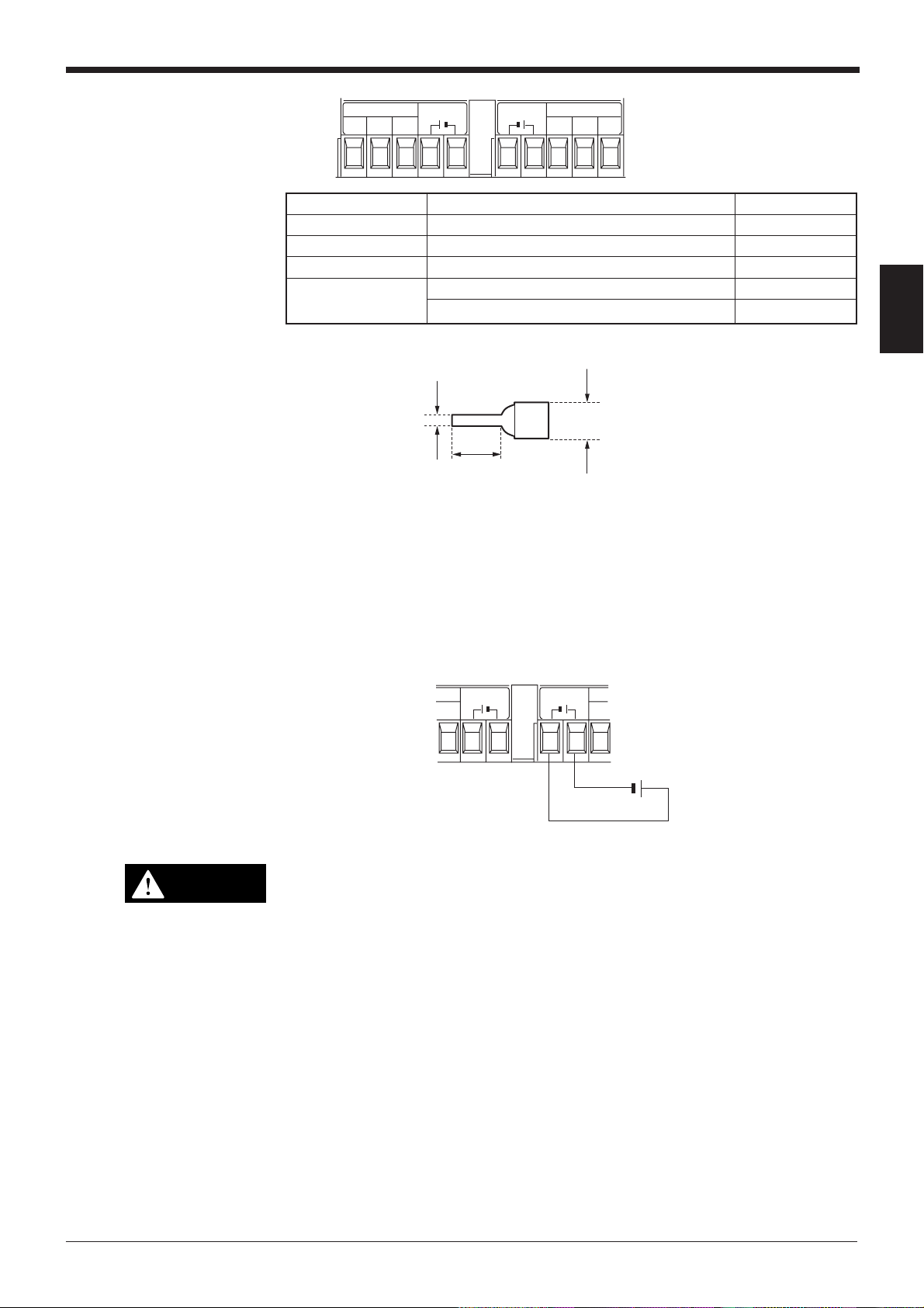
2.3.2 Terminals of I/O terminal block and connections
TIM
COM
OK NG
COM
* Viewed from the left of the unit
Symbol Description Signal direction
TIM Trigger input Input
COM Common terminal for trigger input Input
OK OK output Output
NG NG output Output
COM Common terminal for output Output
16
Page 25
Chapter 2 Installation Procedure
Connecting power supply
RS-485 RS-485
SG SG
Symbol Description Signal direction
RS-485 SG RS-485 signal ground –––
RS-485 + RS-485 + terminal Input/Output
RS-485 - RS-485 - terminal Input/Output
24 VDC IN (OUT) 24 VDC power supply input (output) + terminal Input(Output)
24V DC OUT
++--
24 VDC power supply input (output) - terminal Input(Output)
24V DC IN
+–
* Viewed from the bottom of the unit
• The following I-type clips can be used for connections.
2.0 mm
max.
6 mm min
5 mm max.
2
CAUTION
Connect a 24 VDC power supply to the “IN” terminal.
When a 24 VDC power supply is connected to the “IN” terminal, the “OUT” terminal
can be used as a 24 VDC power supply output terminal. In this case, the “OUT”
terminal can be used as a power supply for other N-48 unit connected in the multidrop link configuration. (➮
For a connection example, see p. 19.
24V DC OUT
--
24V DC IN
+–
24 VDC
+
)
• Do not connect a power supply other than 24 VDC or the unit may be
damaged.
• Connecting a power supply to the RS-485 terminal may damage the N-48.
• Do not connect different types of power supplies to the IN and OUT terminals or the unit may not start normally due to the potential difference
between the power supplies.
17
Page 26
Chapter 2 Installation Procedure
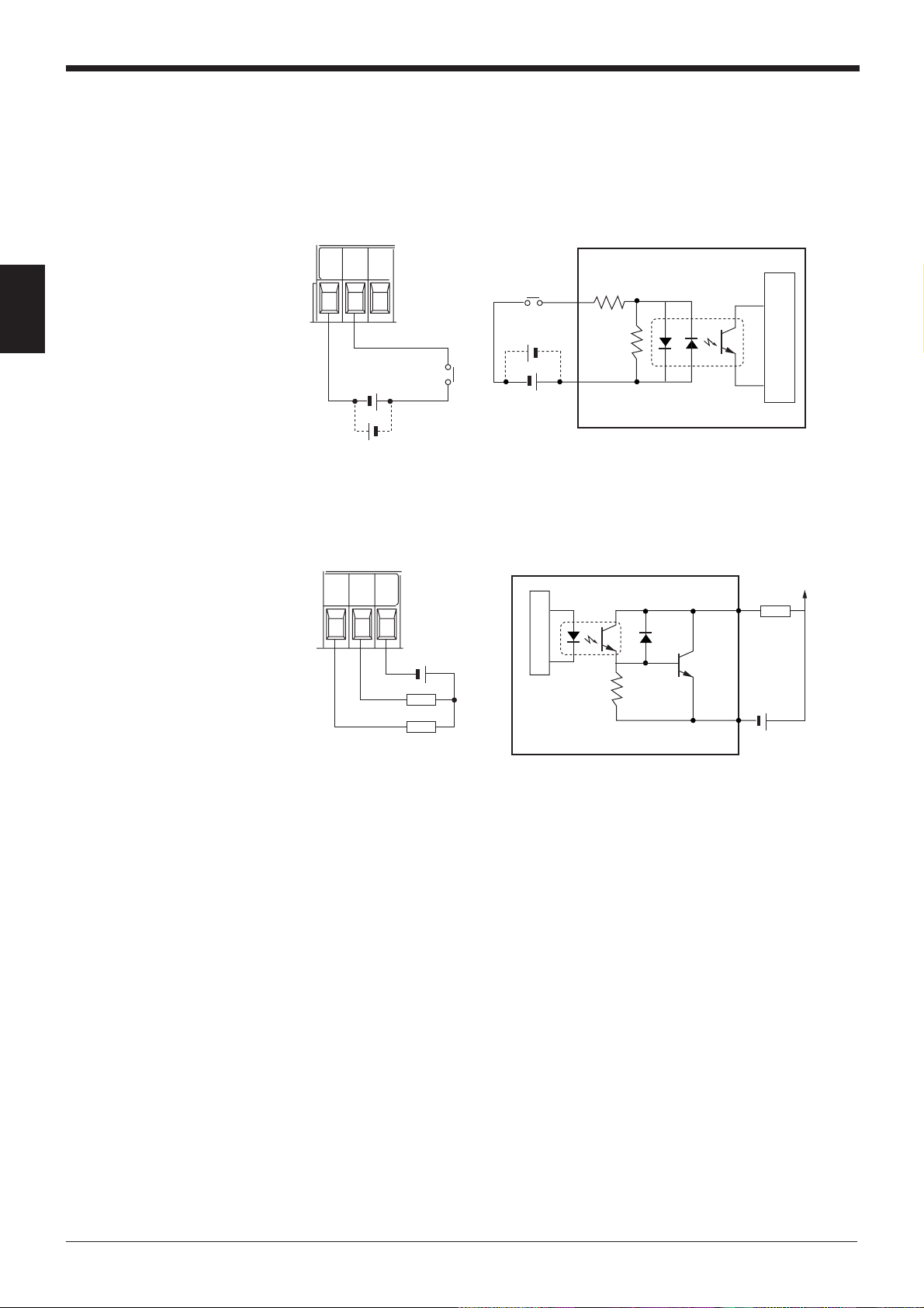
Connecting trigger input
2
Connecting OK/NG output
The trigger input allows the BL series to start reading bar codes (turn on the laser
beam).
To connect the BL series in multi-head mode, send the trigger input to the N-400
instead of the N-48.
TIM
COM
OK
TIM
+
Internal circuit
+
+
15 to 26 VDC
+
COM
The OK/NG output indicates the result of the comparison with preset data, or
indicates whether reading is successful or not.
OK NG
*Rated load: 30 V max. (100mA)
COM
Load
Load
Load
+
Internal circuit
+
18
Page 27

2.3.3 Connecting RS-485
For the RS-485 connections, use the “RS-485 +” and “RS-485 -” terminals provided
on the terminal block.
Chapter 2 Installation Procedure
RS-485 SG
RS-485 +
RS-485 –
24V DC IN +
24V DC IN –
24V DC OUT –
24V DC OUT +
RS-485 +
RS-485 –
RS-485 SG
RS-485 SG
RS-485 +
RS-485 –
24V DC IN +
24V DC IN –
N-48
Shield cable
Twisted pair cable
*
+
24 VDC
TIM
COM
RS-485 SG
RS-485 +
RS-485 –
24V DC OUT +
24V DC OUT –
24V DC IN +
24V DC IN –
N-400
2
24V DC OUT –
24V DC OUT +
RS-485 +
RS-485 –
RS-485 SG
RS-485 SG
RS-485 +
RS-485 –
24V DC IN +
24V DC IN –
24V DC OUT –
24V DC OUT +
RS-485 +
RS-485 –
RS-485 SG
N-48
*
N-48
19
Page 28
Chapter 2 Installation Procedure
• The diagram on the previous page shows the connections to supply 24 VDC
power to the N-48 from the power supply connected to the N-400. In this case,
the 24 VDC power supply connected to the N-400 must have a capacity of at
least “140 mA (N-400 current consumption) + 260 mA (N-48 current consumption) x n (Number of N48 units connected)”.
Example
When five N-48 units are connected:
140 mA + 260 mA x 5 = 1.44 A
Use a power supply with at least 1.44 A capacity.
2
Note: The RS-485 cable can be extended up to 1.2 km. With the power supply
cable, however, the 1.2 km extension is not guaranteed.
To extend the power supply cable as shown in the connection diagram on the
previous page, ensure that the power voltage supplied to all the N-48 units is within
the range of 24 VDC -20% to +10%.
• To connect a 24 VDC power supply to each N-48 unit, remove the 24 VDC
wiring shown in the previous page. To connect the power supply, use the following cable.
Recommended RS-485 cable
• 0.75 mm2 x 2 cores, sheilded
• Up to thirty-one N-48 (BL series) units can be connected in multi-drop link mode.
• The total extension length of the RS-485 cable must be within 1.2 km.
• Turn ON the equipment terminator (termination resistance: 100 Ω) at both ends
of the RS-485 connection (marked with * in the figure above).
• Turn ON/OFF the N-48 terminator using the terminator switch. (
• Turn ON/OFF the N-400 terminator using the terminator switch. (
➮
See p. 7.
➮
See p. 6.
)
)
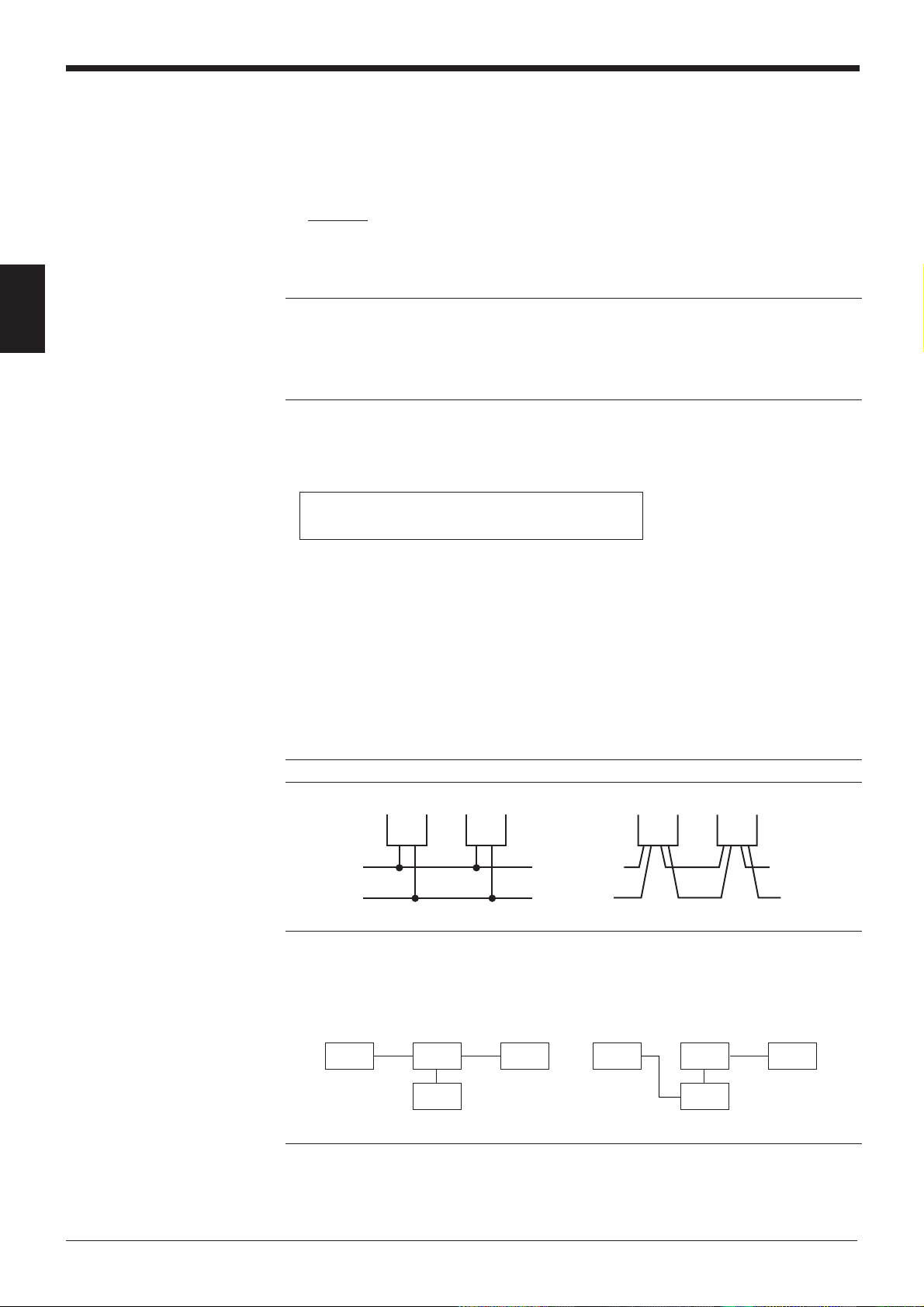
Note: Be sure not to connect the RS-485 cable using the terminal block.
Incorrect
Note 1: Do not place the RS-485 cable in the same conduit as a power cable.
Note 2: Do not branch the RS-485 connection as shown below.
Incorrect
(Connection with branch)
N-48 N-48
N-48
N-400 N-48 N-48
C orrect
(Connection without branch)
*
Correct
N-48
N-400
*
Terminator ON
*
20
Page 29
2.4 Connecting BL-U1 and Wiring
To use the BL-U1 AC power supply, connect it as described below.
2.4.1 Connecting power supply
Plug the BL-U1 power cable into an outlet.
Chapter 2 Installation Procedure
2
FG line
CAUTION
Use a power supply of 100 to 240 VAC ±10% (50/60 Hz).
2.4.2 Connecting BL series
Connect the BL series to the READER port of the BL-U1.
BL-U1 READER port pin assignment
Pin No. Symbol Function Signal direction
1 TIM Trigger input Output
2 RD (RXD) Receives RS-232C data. Output
3 SD (TXD) Sends RS-232C data. Input
4OKOK Input
5 GND (SG) Ground (Common ground for respective —
6NGNG Input
7 RS (RTS) Ready to send RS-232C data. Input
8 CS (CTS) Request to send RS-232Cdata. Output
9 +5 V +5 V power supply (1.5 A) Output
1234
6789
5
D-sub 9-pin (male)
DCE specification (defined as terminal)
#4-40 screw (female)
signal)
(Control method can be selected with the DIP
switches. See p. 22.)
21
Page 30
Chapter 2 Installation Procedure
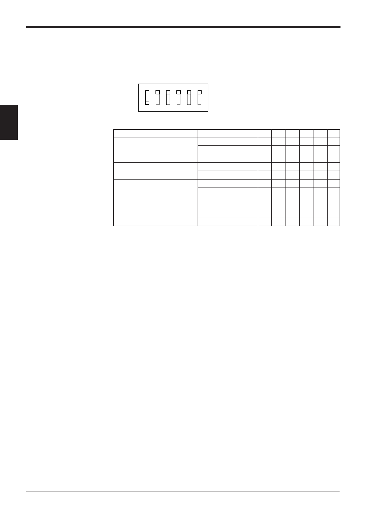
2.4.3 Setting BL-U1 DIP switches
Switch the interface setting to “RS-485 multi-drop” using the BL-U1 DIP switches.
Switch the RS-485 terminator according to p. 25.
OFF
2
ON
123456
Interface selection RS-232C ON OFF OFF
RS-422A terminator OFF OFF
(Termination resistance: 100 Ω)ON ON
RS-485 terminator OFF OFF
(Termination resistance: 100 Ω)ON ON
Selection of READER port ON or OFF according
CS control method to the RS-232C port OFF
* The figure on the left shows the default settings.
DIP Switch No. 1 2 3 4 5 6
RS-422A OFF ON OFF
RS-485 multidrop OFF OFF ON
CS signal status.
Normally ON ON
22
Page 31
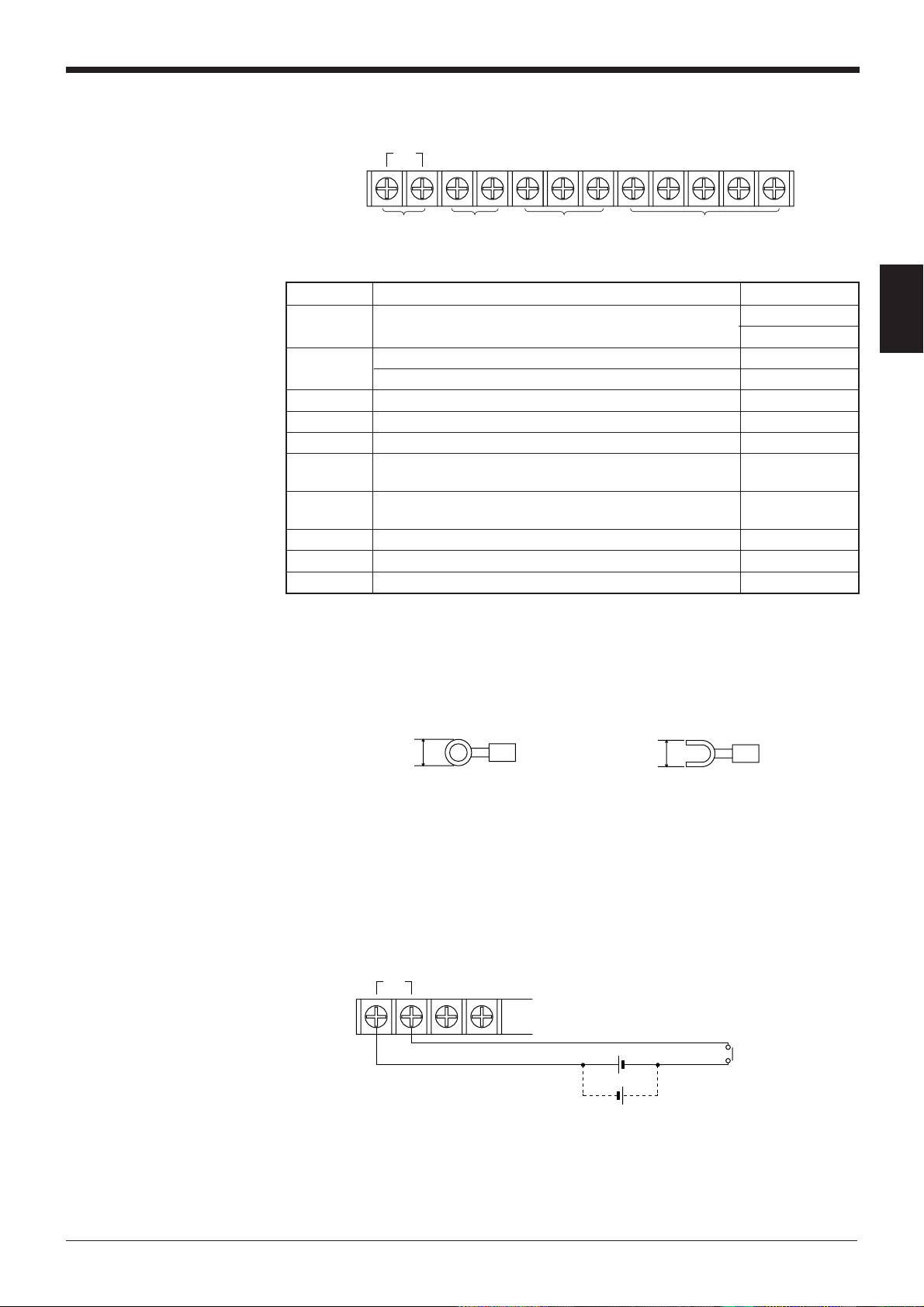
2.4.4 Terminals of I/O terminal block and wiring
TIM +12V OUT– COM OK NG SDA SDB SG RDA RDB
Chapter 2 Installation Procedure
Trigger
input
Symbol Description Signal direction
TIM Trigger input Input
+12 V OUT + terminal of power supply for sensor (12 VDC, 300 mA) Output
– terminal of power supply for sensor (0 V) Output
COM Common terminal for OK/NG output —
OK OK output Output
NG NG output Output
SDA + terminal for RS-422A data transmission/ Output,
RS-485 + terminal Input/Output
SDB – terminal for RS-422A data transmission/ Output,
RS-485 - terminal Input/Output
SG Signal ground —
RDA + terminal for RS-422A data reception Input
RDB – terminal for RS-422A data reception Input
Power supply
for sensors
(12 VDC, 300 mA)
OK/NG output
RS-422A/RS-485
Input
* Viewed from the left of the terminal block
• M3.0 screws are used for the terminal block.
• Use the following crimp terminals for connections.
2
Connecting trigger input
6.0 mm or
less
Round-shape
6.0 mm or
less
Fork-shape
The trigger input allows the BL series to start reading bar codes (turn on the laser
beam).
The trigger input is turned ON when 8.5 to 30 VDC input is activated between the
trigger input terminals.
The BL-U1 power supply for the sensor can be used as the input power supply.
TIM +12V OUT–
+
+
8.5~30VDC
Contact or
solid-state
23
Page 32

Chapter 2 Installation Procedure
Connecting OK/NG output
The OK/NG output is used to differentiate between acceptable and unacceptable
results based on the comparison with the preset data, and to indicate whether or
not the BL series successfully read bar codes.
The OK/NG output is an open-collector output.
COM OK NG
*Rated load: 30 V max. (100 mA)
2
I/O circuit diagram
Input circuit diagram
TIM
Load
Load
+
3.3KΩ
2.4
KΩ
Internal circuit
Output circuit diagram
Internal circuit
OK/NG
COM
Load
+
24
Page 33

2.4.5 Connecting RS-485
Incorrect Correct
BL-U1
BL-U1
For the RS-485 connections, use the “SDA” and “SDB” terminals provided on the
terminal block.
*
Chapter 2 Installation Procedure
BL-U1 BL-U1 BL-U1
SDA
SDB
SG
SDA
SDB
SG
SDA
SDB
SG
*
N-400
RS-485 +
RS-485 –
RS-485 SG
Recommended RS-485 cable
• 0.75 mm2 x 2 cores, shielded
• Up to thirty-one BL-U1 (BL series) units can be connected in multi-drop link
mode.
• The total extension length of the RS-485 cable must be within 1.2 km.
• Turn ON the equipment terminator (termination resistance: 100 Ω) at both ends
of the RS-485 connection (marked with * in the above diagram).
• Turn ON/OFF the BL-U1 terminator using the terminator switch. (See p. 22.)
• Turn ON/OFF the N-400 terminator using the terminator switch. (See p. 6.)
Note: Be sure not to connect the RS-485 cable using the terminal block.
2
Note 1: Do not place the RS-485 cable in the same conduit as a power cable.
Note 2: Do not branch the RS-485 connection as shown below.
Incorrect
(Connection with branch)
BL-U1 BL-U1
N-400 N-400
Correct
(Connection without branch)
BL-U1BL-U1
*
BL-U1
BL-U1
* Terminator ON
*
25
Page 34

Chapter 2 Installation Procedure
2.5 Using Connection Test Mode
This section describes the procedure for performing a connection test after the N400 and the BL series (N-48 or BL-U1) are connected with the RS-485 cable.
Note: To use the connection test mode, ensure that the settings of the connected
BL series and those of the N-400 are switched to “multidrop link” mode.
1) When you press and hold the N-400 test switch for approximately 2 seconds
after the power to all devices is turned ON, the connection test mode is acti-
2
vated. The N-400 displays the ID number of the device being tested. If the
devices are properly connected, the ID number is automatically incremented.
2) If any device is not connected or is improperly connected, the ID number
corresponding to the device flashes.
To go to the next step during the connection test, press the test switch once.
Example 1
When ten BL series (ID Nos. 1 to 10) are connected:
The displayed ID number automatically changes from “1” to “10”, and then “11”
will flash if the connection test result is “OK”.
Example 2
When fourteen BL series (ID Nos. 3 to 16) are connected:
When “1” flashes, press the test switch once. When “2” flashes, press the test
switch again. The displayed number changes from “3” to “16”, and then “17” will
flash if the connection test result is “OK”.
3) If an ID number of any BL series flashes, the BL series unit is not properly
connected. After checking the following points, perform the connection test
again.
• Check that the RS-485 communication parameters (baud rate, data length,
parity and stop bit length) of the N-400 match to those of the BL series.
• Check that the BL series is set to “multi-drop link” mode.
• Check that all cables are properly connected. Ensure that the connections are
not branched and that no cables are connected using the terminal block. (
See pp. 19, 20 and 25.
• Check that the equipment terminators at both ends of the connection are ON
and the terminators of other equipment are OFF.
• Check that the BL series’ ID numbers are properly assigned. Make sure that the
same ID number is not assigned to different devices.
)
➮
26
4) Pressing and holding the test switch for approximately 2 seconds again resets
the connection test mode.
Page 35

2.6 Mounting Procedure
2.6.1 Operating environment precautions
Chapter 2 Installation Procedure
CAUTION
This unit is a precision instrument and you must take care in choosing the
operating environment.
■ Ambient environments
Do not install the unit in place as shown below
• The unit is exposed to direct sunlight, or the ambient temperature may fall
below 0°C (32°F) or exceed 50°C (122°F);
• The relative humidity may exceed the range of 35 to 85%, or condensation may
occur due to rapid temperature changes;
• Corrosive gas or inflammable gas is present, or a high level of dust, salt, iron
particles or soot is present;
• The unit is subject to vibration or impact;
•Water, oil or chemicals may splash the unit;
•A strong magnetic field or electric field is generated.
• Do not place the cables in the same conduit as a power cable.
2
■ In-panel installation
To mount the N-400 in a panel, carefully observe the following instructions.
• Provide enough ventilation space.
• If the ambient temperature may fall below 0°C (32°F) or exceed 50°C (122°F),
provide a fan or air conditioner.
• Do not mount this unit in a panel where a high voltage device is installed.
• Place this unit as far away from power lines as possible.
27
Page 36
Chapter 2 Installation Procedure
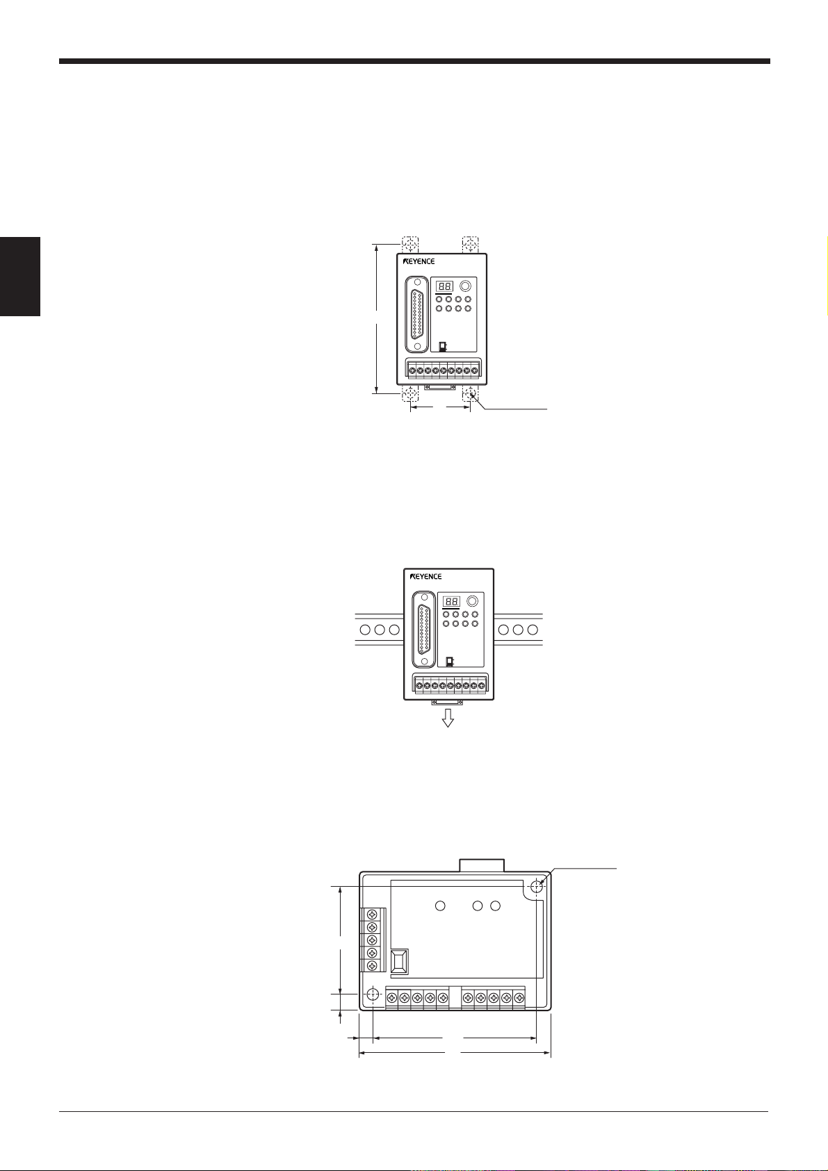
2.6.2 Mounting N-400
Direct mounting
2
To mount the N-400, you can use one of the following two methods:
Pull the brackets provided at four positions on the rear of the N-400, and fix them
with screws.
N-400
TEST
RS-232C
CS RS
SD RD
RD
SD
POWER TIMING
TERMINATOR
RS-455
ON
OFF
100
DIN-rail mounting
2.6.3 Mounting N-48
40
4 x ø5
mounting hole
To mount the N-400 on a DIN-rail, press the unit against the DIN rail until it clicks.
To remove the unit, pull the hook in the direction indicated by arrow.
N-400
TEST
RS-232C
CS RS
SD RD
RD
SD
POWER TIMING
RS-455
TERMINATOR
ON
OFF
28
To mount the N-48, use the mounting hole.
POWER SD RD
43.2
5.9
5.9
63.2
75
4 x ø5
mounting hole
Page 37

2.6.4 Mounting BL-U1
To mount the BL-U1, you can use one of the following two methods:
Positions of direct mounting
Pull the brackets provided at four positions on the rear of the BL-U1, and fix them
with screws.
Chapter 2 Installation Procedure
4 x ø5
DIN-rail mounting
98
150
1. Hook the BL-U1 in the groove of the DIN rail from the top, and press the bottom
of the BL-U1 against the DIN rail until it clicks.
2. Make sure that the DIN-rail mounting hook is set in condition “A”. If it is not,
push it inward.
3. To remove the BL-U1 from the DIN rail, pull the hook so that it is set in condition
“B”.
4. To mount the unit on the DIN rail again, restore the hook to condition “A”.
2
AB
29
Page 38

Chapter 2 Installation Procedure
2
30
Page 39

Chapter 3
N-400 Setup Procedure
3.1 Installing Setup Software ...................................................32
3.2 Setup Software Operating Procedure ...............................34
3.2.1 Operating procedure..............................................................34
3.2.2 Description on each setup screen .........................................35
3.2.3 Outline of operation ...............................................................36
3.3 Details of Operating Procedure ........................................38
3.3.1 Setting procedure ..................................................................38
3.3.2 Reading/Saving/Printing File .................................................44
3.4 Sending/Receiving Settings ..............................................48
3.5 Using Terminal ....................................................................52
3.6 List of Error Messages .......................................................55
Page 40

Chapter 3 N-400 Setup Procedure
3.1 Installing Setup Software
The N-400 includes the setup software for the Windows version only.
The operating environments and the procedure for installing this setup software
are described below.
■ Hardware requirments
• IBM PC/AT 100% compatible
CPU: 80386 or higher
Memory: 4 MB or more
Floppy disk drive: 3.5 inch floppy disk drive (1.44 Mb compatible)
Serial port: A minimum of one RS-232C port is required.
■ OS requirements
3
Installation procedure
• MS-Windows 3.1 or MS-Windows 95
1. Insert the N-400 setup software system disk into the floppy drive.
2. Perform the following procedure.
•Windows 3.1:
Execute “Run” in the icon menu of the program manager.
•Windows 95:
Select “Run” from the "Start" menu.
3. Run the “SETUP” file from the floppy disk drive.
(This step is common to both the Windows 3.1 and Windows 95.)
Type in as follows:
A: \SETUP
32
Page 41

Chapter 3 N-400 Setup Procedure
4. The N-400 setup software installer starts. Follow the instructions in the install
window. (Typically, the installation procedure can be completed simply by
pressing [Next (N)] twice.)
5. The setup software is normally installed in the following directory:
C: \KEYENCE\N400
If this directory is correct, click on [Next (N)]. If you wish to change the directory,
click on [Browse (R)..], and select the desired directory.
6. When installation starts, the file copy process is displayed as a graph. When the
installation is completed, the following message appears.
7. For Windows 3.1, double-click on the [N400] icon in the [KEYENCE] group to
start the setup software.
For Windows 95, start the program from the "Start" menu.
3
33
Page 42

Chapter 3 N-400 Setup Procedure
3.2 Setup Software Operating Procedure
3.2.1 Operating procedure
To set up the N-400 using the setup software, follow the procedure below.
1. Connect the N-400 to the host computer using the RS-232C cable.
➮
For the recommended cable, see 2.2.2 Connecting RS-232C.
2. Start the N-400 setup software.
3. Select a setup item, and set it to the desired condition.
4. Before sending the updated settings to the N-400, click on [COM PORT] to
match the communication parameters of the personal computer with the current
3
settings of the N-400.
The default settings of the N-400 are as follows:
• Baud rate: 9600 bit/s
• Data length: 7 bit
• Parity: Even
• Stop bit length: 1 bit
Immediately after you purchase the N-400, set [COM PORT] to the above
settings.
If you do not know the current settings of the N-400, press the N-400 test switch
for approximately 5 seconds. When the N-400 displays “S0(50)”, the N-400 is
automatically set to the above settings. The N-400 can communicate with the
host computer if the “COM PORT” settings are same as the above.
5. Click on [Transfer] to send the updated settings to the N-400.
(The current settings of the N-400 can also be read.)
6. Select [FILES] to save or print the settings, as required.
7. After the setup procedure is completed, click on [Exit] to close the setup software.
34
Page 43
3.2.2 Description on each setup screen
Chapter 3 N-400 Setup Procedure
▼
▲
Displays the name of the setup file
currently being edited. If the file has
been read from the setup file, the file
name is specified as “File: ...”. If the
file has been read from the N-400, the
file name is marked with “N-400”. If
the file name is the initial setting,
“default” is displayed.
If the file name has been changed
from the initial setting (the condition
immediately after it is read from the
file), “changed” is displayed.
HOST MODE:
• Sets auto-polling mode (multi-drop link) and multi-head scan mode
• Sets the interference suppression function in multi-head mode
• Sets read mode, measuring method and trigger input in multi-head mode
• Sets a read error code and trigger ON/OFF commands in multi-head mode
PROTOCOL:
• Sets the handshaking protocol
• Sets the header and delimiter
• Sets the PLC link
3
ID SETUP:
• Registers the ID number of the connected BL Bar Code Reader
RS-232C:
• Sets the baud rate, data length, stop bit length and parity for the RS-232C
communication
• Setting the RTS/CTS protocol
RS-485:
• Sets the baud rate, data length, stop bit length and parity for the RS-485 communication
FILES:
• Saves, reads or prints settings
COM PORT:
• Sets the communication parameters (baud rate, etc.) of the host computer
according to the settings of the N-400 before communication starts between the
N-400 and host computer.
TRANSFER:
• Sends updated settings to the N-400, or reads the current settings of the N-400.
MONITOR:
• Checks if the N-400 can operate normally.
EXIT:
• Quits the N-400 setup software.
35
Page 44

Chapter 3 N-400 Setup Procedure
3.2.3 Outline of operation
This section describes the basic operations of the N-400 setup software.
To enter settings, place the mouse pointer on the item to be changed, and click the
left mouse button.
Mouse pointer
3
Clicking on
Clicking on
Clicking on
• • •
Used to select the item to be changed.
Used to select any of several options.
The selected item is marked with • .
Used to select whether to enable or disable this function.
To enable this function, the mark is checked with “√”. (For the Windows Ver. 3.1,
it is checked with “x”.)
Clicking on
➞
Used to select any of several options.
36
Page 45

Entering a value
Entering characters
Chapter 3 N-400 Setup Procedure
After clicking in the frame, enter a value using the keyboard.
If the entered value exceeds the setting range, an error message is displayed.
(
➮
See p. 55.
When you click in the frame labeled “ASC”, you can enter characters using the
keyboard.
When you click in the frame labeled “HEX”, you can enter characters using hexadecimal numbers (00 to 7F). This function is used to enter control characters (00 to
21h ASCII codes, such as [CR] and [STX]).
)
3
37
Page 46

Chapter 3 N-400 Setup Procedure
3.3 Details of Operating Procedure
3.3.1 Setting procedure
HOST MODE
In the HOST MODE, select “Multi-drop link” or “Multi-head scan”.
3
1. If you select “Multi-head scan” mode, the following setup items appear. The
following steps are effective for “Multi-head scan” mode only.
2. To use the “Interference Suppression” function, the following setup items
appear.
38
“TIMER” indicates the reading time of each BL series in the interference suppression mode. Enter a value using the keyboard.
3. “Data-send” is displayed only when “Read mode” is set to “Single”.
4. Enter a read error code using the keyboard. The read error code can be
changed to any eight character string. Set this code so that it conforms to the
read error code of the connected BL series.
Normally, you should use the default setting (ERROR) without changing it (as
well as the BL series’ read error code).
Page 47

5. When you click on [Trigger setup], you can set the trigger input in multi-head
mode.
➮
Tips
MULTI-DROP LINK (Multi-drop link mode): p. 58
➮
MULTI-HEAD SCAN (Multi-head scan mode): p. 86
➮
Interference Suppression: p. 95
➮
Read mode: pp. 89 to 90
➮
Data-send: p. 92
➮
Read error code: p. 93
TRIGGER SETUP (only when Multi-head scan is selected)
The Trigger Setup screen is used to set the trigger input for Multi-head scan mode.
Chapter 3 N-400 Setup Procedure
3
Tips
1. Set “Trigger Input/Signal Type” to “Level” or “One-shot”.
If you select “One-shot”, the one shot input time is displayed.
2. Enter the “Command for Trigger ON” and “Command for Trigger OFF” using the
keyboard. These commands can be changed to any eight character string. Set
these commands so that they conform to the trigger ON/OFF commands of the
connected BL series.
Normally, you should use the default settings (LON and LOFF) without changing them (as well as the BL series’ trigger ON/OFF commands).
➮
Trigger Input/Signal Type: p. 91
➮
Command for Trigger ON, Command for Trigger OFF: p. 72
39
Page 48

Chapter 3 N-400 Setup Procedure
PROTOCOL (when "Use PLC" is disabled)
The PROTOCOL screen is used to set “Handshaking protocol” and various items
to enable the "Use PLC".
3
1. When “Use PLC” is disabled, set the “Handshaking protocol” as shown above.
2. Select “Header” and “Delimiter” from the displayed items. You can change the
read data format by setting these items. If you select “Custom”, the following
screen appears. These items can be set to any five character string using the
keyboard.
Note: When customizing the header and delimiter, you modify them based on the
previously selection. When selecting "custom," if you currently use "CR", "0D"
appears in hex and "." in ASCII (It is not a period but stands for "CR"). If "none"
was used previously, nothing appears.
3. Normally, the ID number of the BL series that executed reading is not added to
the read data in multi-head scan mode. However, you can set “Add ID” so that
the ID number is added to the read data.
4. “Checksum” can be added to read data to check incompatible data translation
between the N-400 and the host computer. Normally, this function is not necessary.
40
Tips
➮
Handshaking protocol: pp. 65 and 66
➮
Header, Delimiter: p. 61
➮
Checksum: pp.133 and 134
Page 49
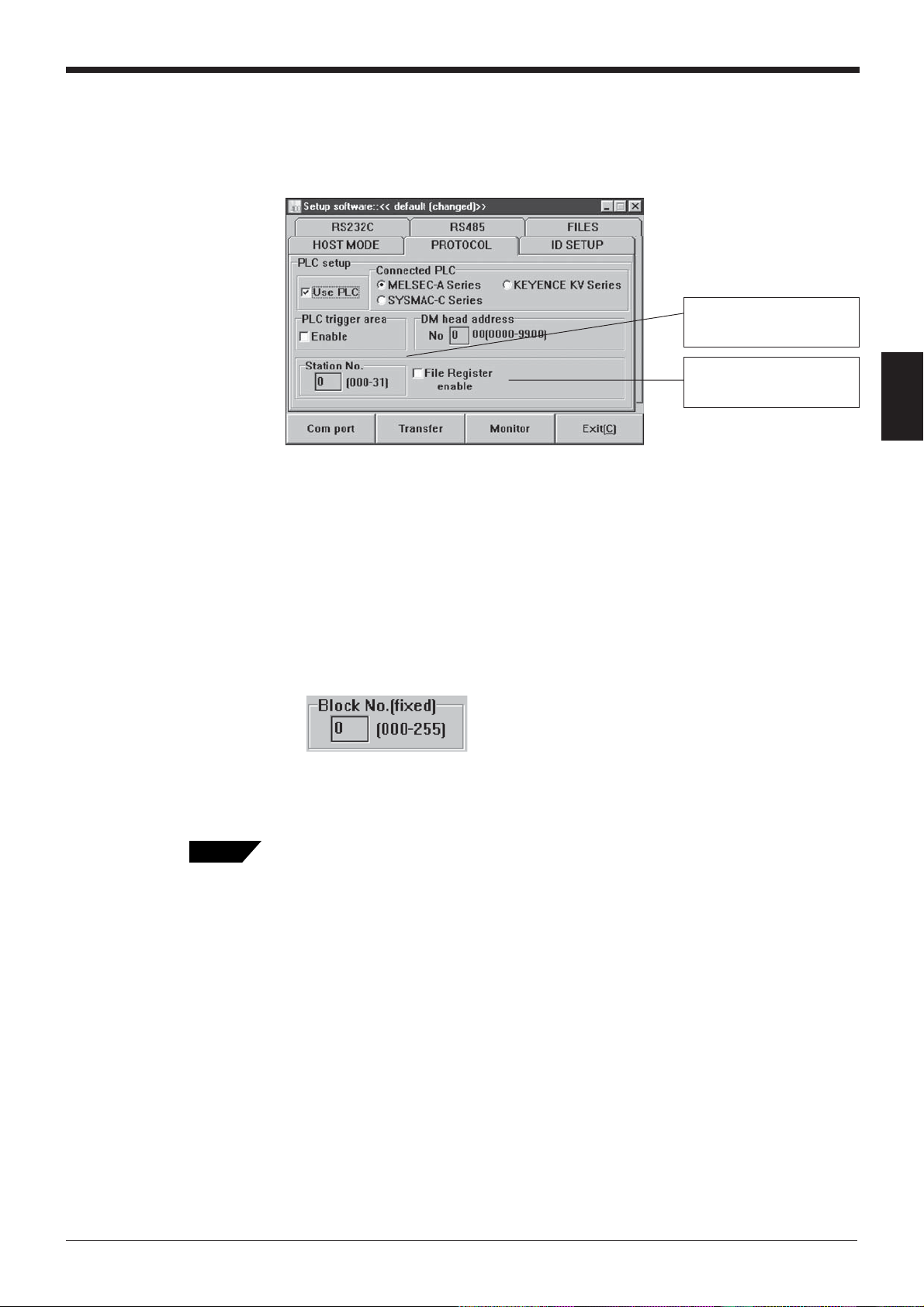
PROTOCOL (when "Use PLC" is enabled)
To enable the "Use PLC", set each item as follows:
S018
Chapter 3 N-400 Setup Procedure
The setting of the station
number is not displayed
▼
▼
when “KV Series” is selected.
The setting of the file register
is displayed only when
“MELSEC-A” is selected.
3
Tips
1. Set “Connected PLC”, “DM head address” and “Station No.”.
To set “DM head address”, enter a value (0000 to 9900) using the keyboard.
2. To send a trigger signal to the BL series when the PLC link is enabled, set
“PLC trigger area”.
3. To use “File Register”, set “File Register” to “Enable”. When “File Register” is
enabled, the following screen appears. The “File Register” can be used with
the Mitsubishi MELSEC-A series only.
Enter the block number (000 to 255) of the file register using the keyboard.
➮
PLC link: p. 100
➮
PLC trigger area: p. 106
➮
DM head address: p. 106
➮
File register: p. 101
41
Page 50

Chapter 3 N-400 Setup Procedure
ID SETUP
3
The ID SETUP screen is used to register the ID numbers of the connected BL
series. When you register the ID numbers in multidrop link mode, polling automatically starts when the N-400 starts up. To perform manual polling, skip the ID
SETUP.
RS-232C
Tips
➮
Auto polling: p. 61
➮
Manual polling: p. 62
The RS-232C screen is used to set the RS-232C communication parameters for
the N-400. Set these parameters so that they conform to those of the host computer or PLC.
42
Tips
1. Setting “RTS/CTS” is disabled when “Use PLC” is selected.
➮
RTS/CTS: p. 66
Page 51

RS-485
Chapter 3 N-400 Setup Procedure
The RS-485 screen is used to set the RS-485 communication parameters for the
N-400. Set these parameters so that they conform to those of the connected BL
series.
3
Note: We recommend that you set the baud rate to “38400 bits/s” to increase the
processing speed, since the RS-485 communication between the N-400 and the
BL series transfers a large volume of data.
43
Page 52

Chapter 3 N-400 Setup Procedure
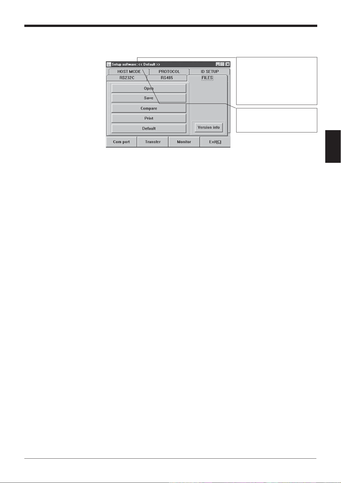
3.3.2 Reading/Saving/Printing File
The FILES screen is used to save updated settings in a file, to read a saved setting
file, and to print the contents of a setting file.
3
• Open: Reads a saved setting file.
• Save: Saves updated settings in a file.
• Compare: Compares the settings currently edited with a file previously saved.
• Print: Prints contents of a setting file.
• Default (Initialize settings): Restores updated settings to the default settings.
• Version info: Displays the version information of this software.
Reading a previously saved setting file
1. To read a previously saved setting file, click on [Open]. The following screen will
appear.
44
2. When you click on [OK] after selecting a file, the selected file can be opened.
Page 53
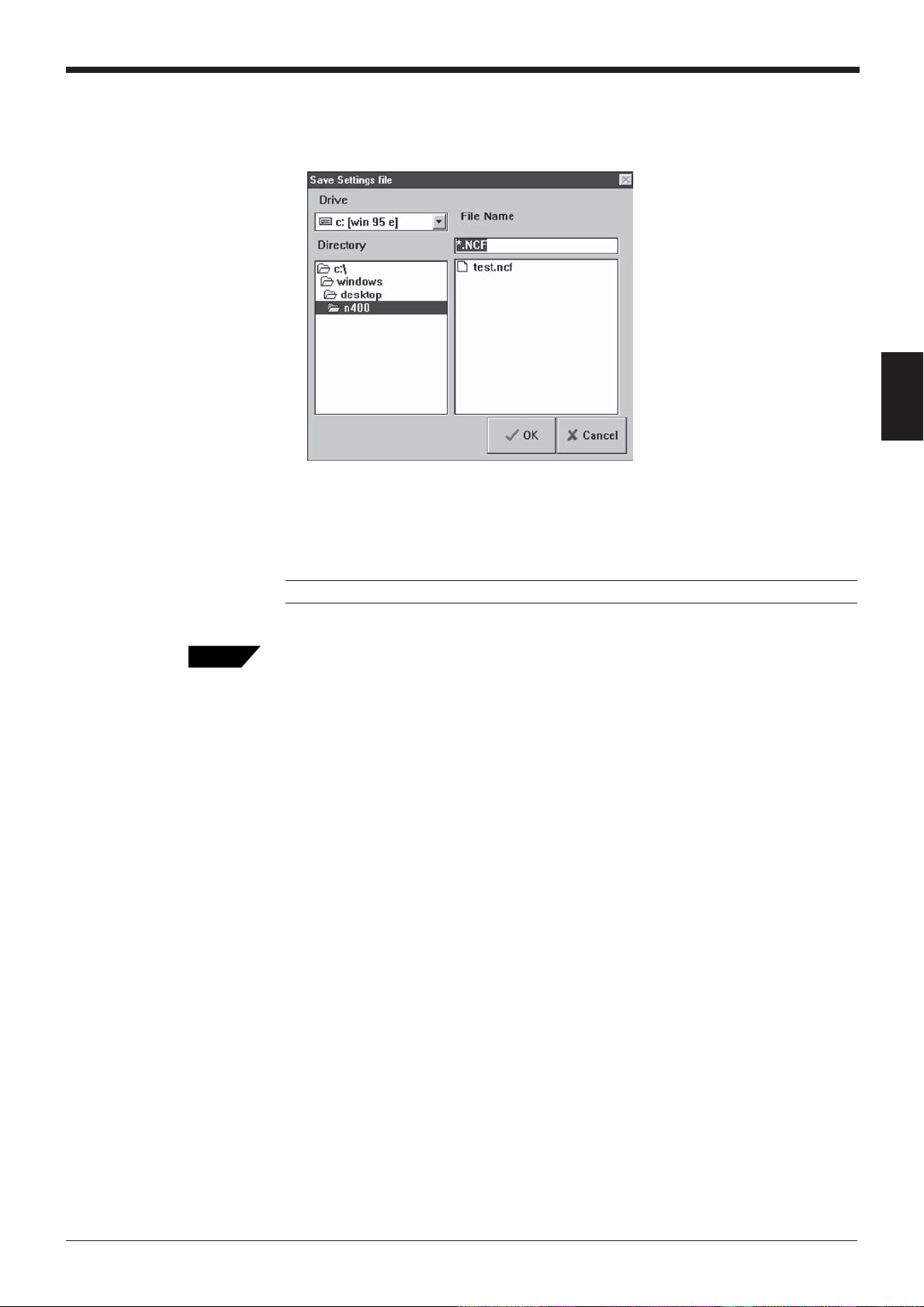
Saving updated settings in a file
1. To save updated settings in a file, click on [Save]. The following screen will
appear.
2. Click on the file name entry field, and enter a file name using the keyboard.
Specify a file name within eight characters. Be sure to add the extension “NCF”.
After entering the file name, click on [OK] to save the file.
Chapter 3 N-400 Setup Procedure
3
Tips
Note: This software cannot accept a long file name in Windows 95.
When the saved setting file is sent to the N-400, the name of the file is simultaneously sent to the N-400. When you read the settings of the N-400 using this
software, the file name is also read. It is convenient for maintenance since you can
find the file that stores the settings.
To enter a file name, use alphanumerics (letters and numbers) only. Otherwise, the
file name cannot be sent to the N-400, because it can only recognize alphanumerics. To send a file name, be sure to enter the file name using alphanumerics and
then save it. (If the file name is not saved, it cannot be sent to the N-400.)
45
Page 54

Chapter 3 N-400 Setup Procedure
Comparing the settings currently edited with a saved file
1. To compare the settings currently edited with the setting file previously saved,
click on [Compare].
3
2. Select a file to be compared, and click on [OK]. Then, the system compares the
selected file with the settings currently edited, and displays the result.
Matched Not matched
46
Page 55

Chapter 3 N-400 Setup Procedure
Printing contents of a setting file
1. To print settings, click on [Print]. The following screen will appear.
2. Adjust “Printer Setup” as required, and click on [OK]. Printing will then start.
Restoring the settings currently edited to the default (initial) settings
3
1. To restore the settings currently being edited to the default settings, click on
[Default (Initialize settings)].
2. If you try to initialize the settings currently being edited without saving them, the
following message appears. If you wish to execute initialization, click on [OK].
Note: The initialization procedure described in this section is used to initialize the
settings being edited with the setup software. The settings on the N-400 cannot be
initialized.
47
Page 56

Chapter 3 N-400 Setup Procedure
3.4 Sending/Receiving Settings
Sending updated settings to the N-400
To send updated settings to the N-400, perform the following procedure.
1. Press and hold the N-400 test switch for five seconds. When the N-400 displays
“S0 (50)”, the communication parameters are temporarily set as follows:
• Baud rate: 9600 bits/s
• Step bit length: 1 bit
• Data length: 7 bits
• PLC link: Disabled
• Parity: Even
3
Tips
If you know the current communication parameter settings of the N-400, this step is
not necessary. You can send data to the N-400 by setting the communication
parameters of the host computer using [COM PORT] so that they conform to the
current settings of the N-400. However, if PLC link is enabled, you cannot send
data to the N-400 without performing this step because the handshaking protocol is
set for PLC link only.
2. Click on [COM PORT] to set the communication parameters of the host computer according to the values listed in the step 1. (above procedure). Select an
RS-232C port, and click on [OK].
3. Click on [Send setting (Save in N-400 EEP-ROM]. The updated settings are
then sent to the N-400.
48
Page 57
Chapter 3 N-400 Setup Procedure
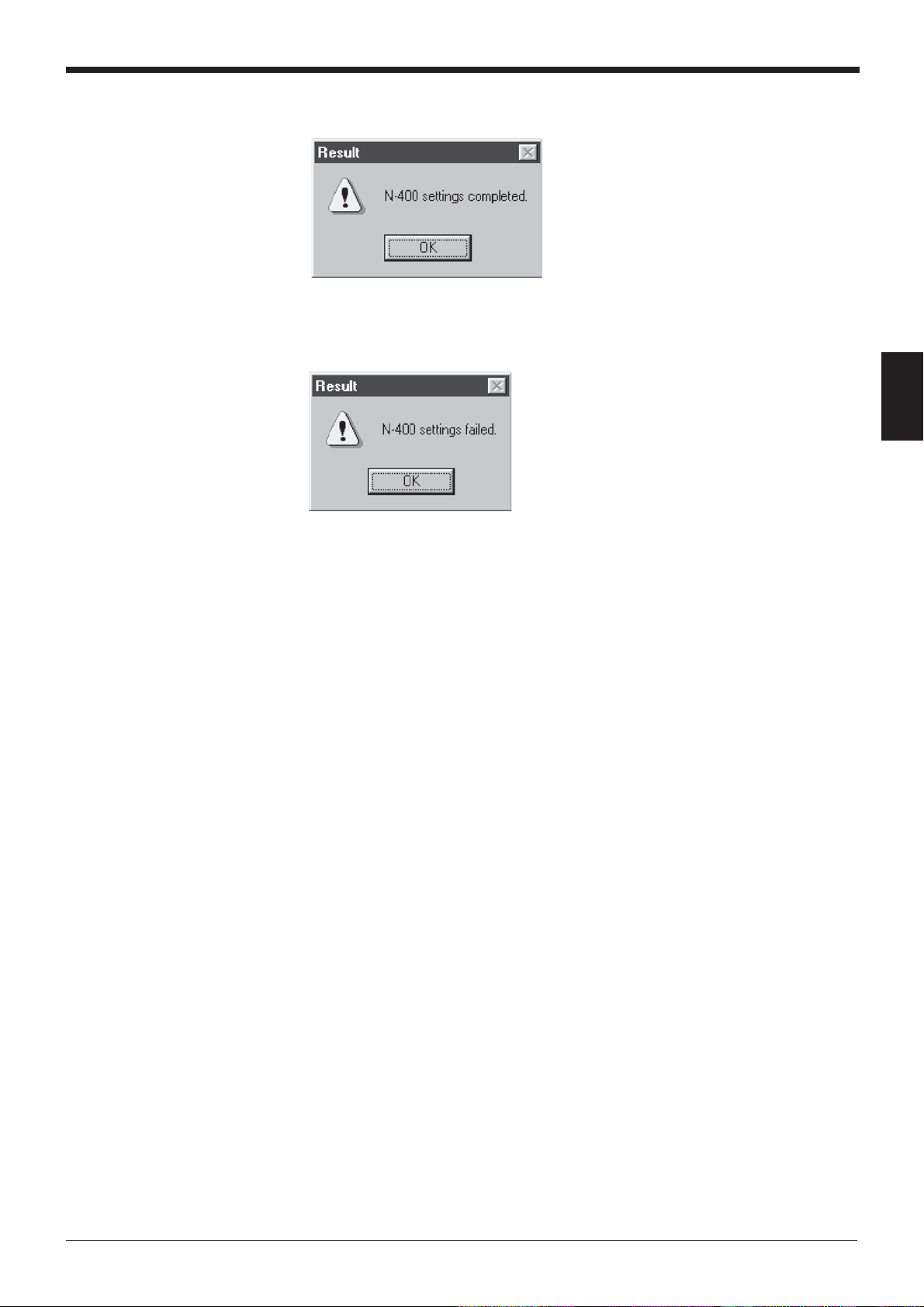
4. If the settings were successfully sent to the N-400, the following message
appears.
If the host computer failed to send the data to the N-400, the following message
appears.
3
If this message is displayed, check the following points:
• Check that [COM PORT] is set to the values listed in step 1. when the N-
400 displays “S0 (50)”.
• Check that the power to the N-400 is ON.
• Check that the RS-232C cable pin assignment of the N-400 is the same as
that of the host computer.
5. After the settings are sent, press the N-400 test switch once to reset the “S0
(50)” condition. (If the N-400 does not display “S0 (50)”, you do not need to
press the test switch. )
When the N-400 displays “00”, the sending procedure is completed. (The
communication parameters of the N-400 are set to the updated settings.)
49
Page 58

Chapter 3 N-400 Setup Procedure
Reading the current settings of the N-400
To read the current settings of the N-400, perform the following procedure. (This
procedure is almost the same as the procedure for sending settings.)
1. Press and hold the N-400 test switch for five seconds. When the N-400 displays
“S0 (50)”, the communication parameters are temporarily set as follows:
• Baud rate: 9600 bits/s
• Data length: 7 bits
• Parity: Even
• Step bit length: 1 bit
• PLC link: Disabled
3
Tips
If you know the current communication parameter settings of the N-400, step 1. is
not necessary. You can send data to the N-400 by setting the communication
parameters of the host computer using [COM PORT] so that they conform to the
current settings of the N-400. However, if PLC link is enabled, you cannot send
data to the N-400 without performing step 1., because the handshaking protocol is
set for PLC link only.
2. Click on [COM PORT] to set the communication parameters of the host computer according to the values listed in step 1. Select an RS-232C port and click
on [OK].
50
3. Click on [Send setting (Save in N-400 EEP-ROM)].
When you click on [Read N-400 settings], the settings of the N-400 can be read
on the host computer.
Page 59

Chapter 3 N-400 Setup Procedure
4. If the settings of the N-400 were successfully read, the following message
appears.
If the host computer failed to read the data, the following message appears.
3
If this message is displayed, check the following points:
• Check that [COM PORT] is set to the values listed in step 1. when the N-
400 displays “S0 (50).”
• Check that the power to the N-400 is ON.
• Check that the RS-232C cable pin assignment of the N-400 is the same as
that of the host computer.
5. After the settings are read, press the N-400 test switch once to reset the “S0
(50)” condition. (If the N-400 does not display “S0 (50)”, you do not need to
press the test switch. )
When the N-400 displays “00”, the reading procedure is completed.
51
Page 60

Chapter 3 N-400 Setup Procedure
3.5 Using Monitor
3
This setup software provides the “Monitor” program to check if the N-400 can send
data properly. The “Monitor” program allows you to display the data read by the BL
series on the host computer’s monitor screen, and also to send a command from
the host computer to the N-400 or BL series.
1. Click on [COM PORT] to set the communication parameters of the host computer according to the current settings of the N-400.
2. Click on [Monitor]. The MONITOR screen will appear.
3. When the BL series reads bar codes, the data read by the BL series is listed on
the screen (in the [Received Data] field). A record of up to 1000 lines of data
can be obtained. Using the scroll bar at the right of the [Received Data] field,
you can see the previous data.
4. If you click [Stop], received data is not listed. (The button name is changed to
[Start].) If you try to display received data again, click on [Start].
52
Page 61
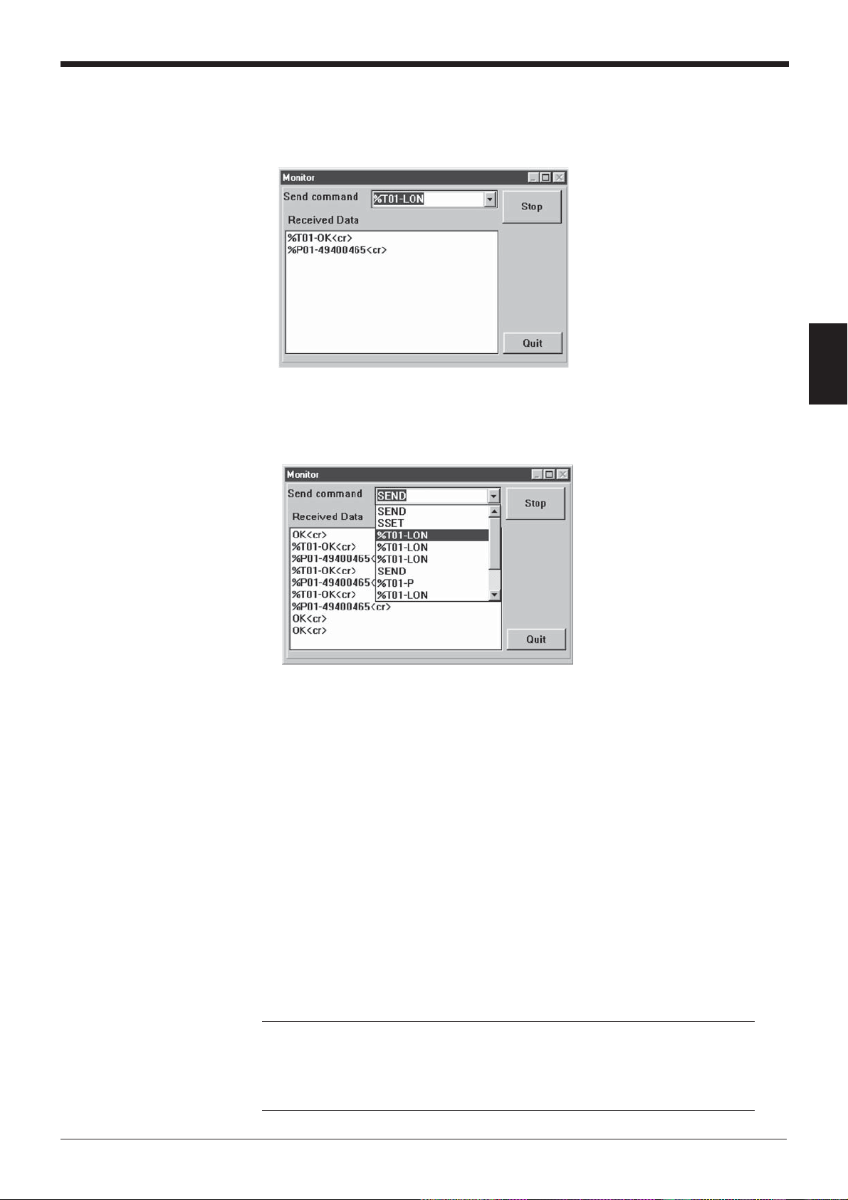
Chapter 3 N-400 Setup Procedure
5. When you enter a command in the “Send command” field, you can send
the command to the N-400 (or BL series). The format of the command to
be sent is “[Command] + [CR]”. Typing command and pressing [ENTER]
key sends the command.
6. When you click on the [ARROW] button in the “Send command” field, the
commands previously sent are listed. (Up to 100 commands can be listed.)
3
7. Click on [Quit] to quit this mode.
Procedure for starting BL test mode using the “Monitor” screen
To start the BL series “Reading rate check” mode by sending a command
from the host computer to the N-400 in multidrop link mode, send the command using the “Monitor” screen according to the procedure below.
■ Using the N-400 in multi-drop link mode
1. Send the “Specific ID polling” command (see p. 72) so that polling is
performed only for the BL series to be tested. To send the command using
the Monitor screen, be sure to enter the command using uppercase
characters. [CR] of the following command corresponds to the [Enter] key
of the personal computer.
POLEmm[CR] * mm = 01 to 31 (ID number of BL series)
Note: When only a few BL series units are connected, you need not send this
command. However, when many BL series units are connected, the cycle of
the N-400’s polling for each BL series becomes longer than the reading cycle
of the test mode, causing the data to be stored in the N-400 buffer. To prevent
this, be sure to send the above command.
53
Page 62

Chapter 3 N-400 Setup Procedure
3
2. Send the test mode command to the BL series to be tested. When the test
mode is started, data read by the BL series is listed in the [Received Data] field
of the Monitor screen.
%Tmm-TEST1[CR] * mm = 01 to 31: ID number of BL series
3. To quit the test mode, send the test mode end command.
%Tmm-QUIT[CR] * mm = 01 to 31: ID number of BL series
4. To continue the test mode with a BL series of a different ID number, repeat
steps 1. to 3.
5. When you finish using the test mode, reset the “Specific ID polling” command. If
the auto polling mode is selected, send the “Auto polling ON” command. If the
manual polling mode is selected, send the “Auto polling OFF” command.
• Auto polling: POLE00[CR]
•Manual polling: POFF[CR]
■ Using the N-400 in multi-head scan mode
1. Send the “Specific ID polling” command (see p. 72) so that polling is performed
only for the BL series to be tested. To send the command using the Monitor
screen, be sure to enter the command using uppercase characters. [CR] of the
following command corresponds to the [Enter] key of the personal computer.
POLEm[CR] * mm = 01 to 31 (ID number of BL series)
Note: In multi-head scan mode, the N-400 performs polling only when the BL
series read bar codes. Therefore, to use the test mode, you need to send the
“Polling ON” command or “Specific ID polling” command before starting the test
mode so that polling is always enabled.
2. Send the test mode command to the BL series to be tested.
%Tmm-TEST1[CR] * mm = 01 to 31: ID number of BL series
3. To quit the test mode, send the test mode end command.
%Tmm-QUIT[CR] * mm = 01 to 31: ID number of BL series
4. To continue the test mode with a BL series of a different ID number, repeat
steps 1. to 3.
54
5. When you finish using the test mode, send the “Polling OFF” command.
POFF[CR]
Page 63

3.6 List of Error Messages
Error message Contents
Chapter 3 N-400 Setup Procedure
Errors
during
setup
Errors
communication
Errors file
editing
“Timer value incorrect. [OK]” The setting of the trigger ON time exceeds
the range of 1 to 255 (x10 ms) in the interference suppression mode.
“Station number incorrect.”
[OK]
“Block number incorrect.
[OK]”
“N400 settings failed. [OK]”
“N-400 failed to open. [OK]” Communication with N-400 (for reading
“Accessing file during
rejected. [OK]”
“File not found. [OK]” The file name is incorrect. Enter a correct file
“File name incorrect. [OK]”
The setting of the station number exceeds
the range of 000 to 255.
The setting of the block number exceeds the
range of 0 to 255 when the file register is
used in PLC link.
Communication with N-400 (for sending
settings) is abnormal.
settings) is abnormal.
No floppy disk is inserted. The floppy disk is
write-protected.
The floppy disk is full.
name.
3
55
Page 64

Chapter 3 N-400 Setup Procedure
3
56
Page 65

Chapter 4
Multi-Drop Link Mode Control Procedure
4.1 Multi-Drop Link Mode .........................................................58
4.1.1. Controlling multi-drop link mode ............................................58
4.1.2 Setup procedure ....................................................................60
4.2 Data Communication in Multi-Drop Link Mode ................61
4.2.1 Auto polling ............................................................................61
4.2.2 Manual polling........................................................................62
4.2.3 Capacity of Transmission Buffer............................................63
4.2.4 Handshaking protocol ............................................................65
4.3 Command Transmission To BL Series .............................66
4.4 N-400 Direct Control Commands ......................................69
4.4.1 Communication procedure.....................................................69
4.4.2 Description of commands ......................................................70
4.5 N-400 Setup Command ......................................................75
4.6 Communication Time Consideration .................................83
Page 66

Chapter 4 Multi-Drop Link Mode Control Procedure
4.1 Multi-Drop Link Mode
4.1.1. Controlling multi-drop link mode
Multi-drop link mode can control up to thirty-one BL series units through a host
computer.
Since the complex communication (RS-485 communication) between each BL
series unit and the N-400 is controlled by the N-400, the host computer controls the
communication with the N-400 only, and consequently can be operated with a
simple program. (The ID number assigned to the header of the transmitted data
allows you to identify the BL series unit that sent the data.) Therefore, multi-drop
link mode provides a system configuration that allows use of a simpler program on
the host computer.
The procedures for controlling the N-400 through a host computer are classified
into the following three methods:
• Data communication: Used to send bar code data read by the BL series to the
host computer.
4
• Command communication to the BL series: Used to send commands to the BL
series.
• Command communication to the N-400: Used to control the N-400 directly or
change the settings of the N-400.
* All of the above communication is performed using ASCII codes.
Details on these control methods are described on the following pages.
58
Page 67

Setting the Baud Rate of the BL Series
In order to increase the response speed of the BL-500/180 series when it is connected in the multi-drop link mode through the N400, we recommend that the baud
rate for RS-485 communication between the BL-500/180 series and the N-400 be
set to 38400 bps.
The baud rate cannot be set through normal operations to between 19200 and
38400 bps with the BL series setup software included with the BL-500/180 series.
(The baud rate can be set to be in the above range using serial commands.)
However, the BL-500/180 series’ baud rate can be set between 19200 and 38400
bps by performing the following procedure. (The following procedure is not described in the “BL-500/180 Series User’s Manual”.)
The following procedure refers to the BL-180 series setup software. The procedure
is exactly the same for the BL-500 series.
1. Display the “Communication Setup” screen with the BL series setup software.
Chapter 4 Multi-Drop Link Mode Control Procedure
4
2. Select either “7 bits” or “8 bits” for the “data length” parameter on the communication setup screen by clicking on the appropriate value. (The selected item is
enclosed in a dotted line box.)
3. Press the [@] key once.
4. After the above operation, select “baud rate”. Baud rates of 19200 to 38400 bps
are added to this parameter. Select the desired baud rate.
* Perform the above operation every time you start the setup software.
59
Page 68

Chapter 4 Multi-Drop Link Mode Control Procedure
4.1.2 Setup procedure
For setup and connection procedures, see p. 10. This section describes the procedures for setting the N-400, BL series and host computer only.
Setting the BL series
Using the BL setup software or serial communication, set the BL as follows:
1. Set “Multi-drop Link” to “Enable”.
2. Assign ID numbers (1 to 31) to the connected BL series. Be sure not to assign
the same ID number to different units.
3. Set the RS-485 communication parameters (baud rate, data length, parity and
stop bit length) for the BL series according to the N-400’s settings. The default
settings for the BL series and the N-400 are as follows:
Baud rate: 9600 bps
Data length: 7 bits
Parity: Even
4
Stop bit length: 1 bit
Setting the N-400
Note: To increase the response speed, set the BL series’ baud rate to 38400 bps.
4. Setting “Handshaking protocol” or “RTC/CTS” is not effective.
5. Set “Header” to “None”. Setting “Delimiter” is not effective.
* Set other parameters as required.
Using the N-400 setup software, set the N-400 as follows:
1. Set the host mode to multi-drop link mode. (
2. Set the handshaking protocol on the “PROTOCOL” screen. (
3. Enter the ID numbers of the connected BL series on the “ID SETUP” screen.
(
➮
See p. 41.
To perform manual polling, do not register ID numbers.
4. Set the baud rate, data length, parity and stop bit length according to the host
computer’s settings on the “RS-232C” screen. (
5. Set the baud rate, data length, parity and stop bit length according to the BL
series’ settings on the “RS-485” screen. (
)
➮
See p. 38.
➮
➮
See p. 43.
)
See p. 42.
)
➮
See p. 40.
)
)
Setting the host computer
60
Note: To increase the response speed, set the RS-485 communication baud rate
to 38400 bps. (Set the BL series’ baud rate to this value as well.)
Set the RS-232C communication parameters (baud rate, data length, parity and
stop bit length) for the host computer according to the N-400’s settings.
Page 69
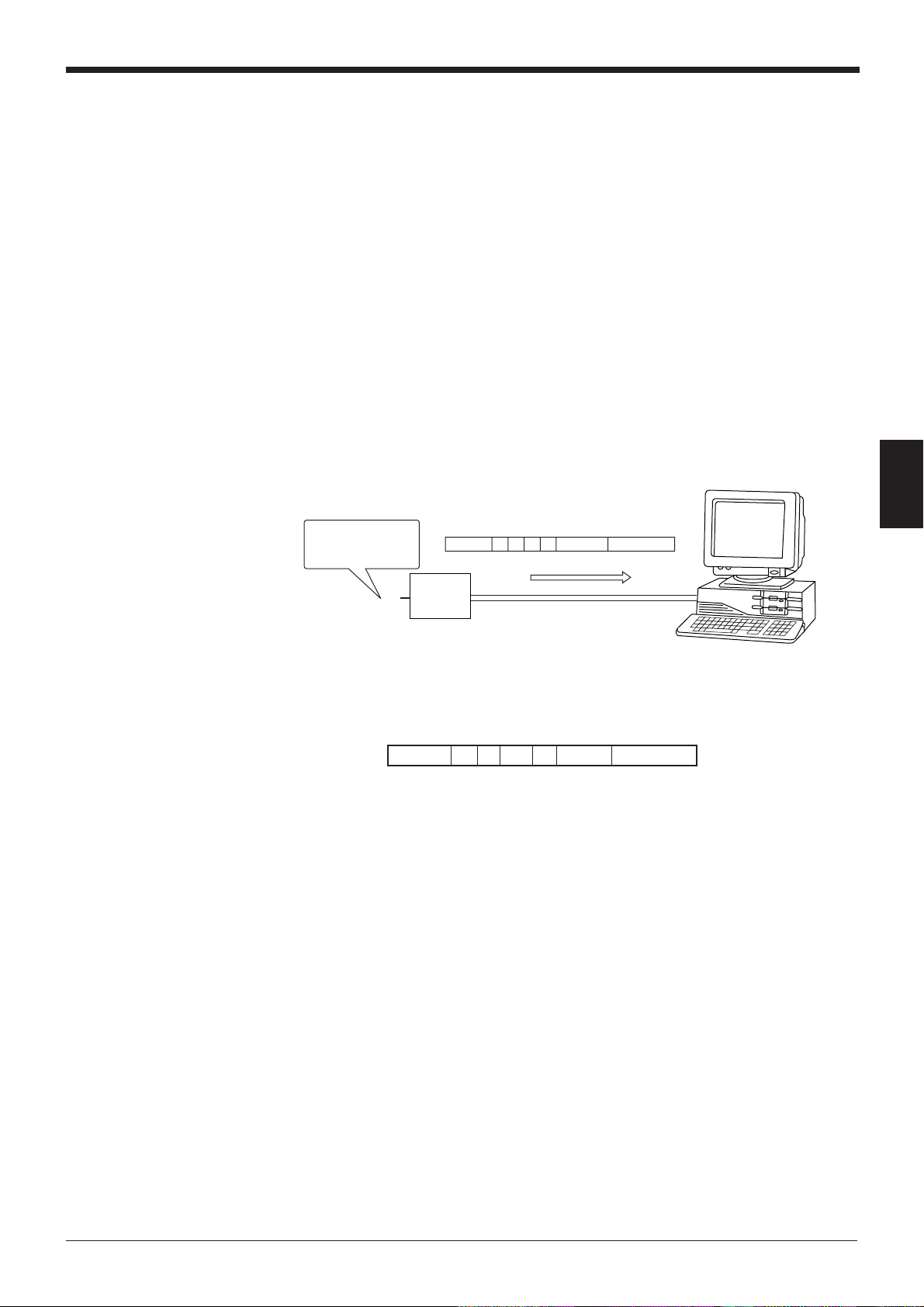
Chapter 4 Multi-Drop Link Mode Control Procedure
4.2 Data Communication in Multi-Drop Link Mode
In multi-drop link mode, the bar code data read by the BL series is sent to the host
computer through either “Auto polling” or “Manual polling”.
The following sections describe these polling methods individually.
You should normally use auto polling mode.
4.2.1 Auto polling
■ Auto polling mode
When the ID numbers of the BL series connected to the N-400 have been registered in auto polling mode, the N-400 automatically executes polling (queries the
BL series of the specified ID number about its data). The obtained data is constantly sent to the host computer from the N-400.
Since the N-400 automatically queries the BL series about its data, the host computer can be operated using a simple program.
■ Communication format
4
The BL series with ID
No. 3 reads bar code
data as “ABC123”.
• • •
In auto polling mode, the N-400 sends the read data to the host computer in the
following format:
Header % P mm – (Data) Terminator
• mm = 01 to 31: ID number of BL series
• (Data) = Read data
OVER: “BUFFER OVERFLOW” error has occurred. (
• Select the header and delimiter from the following formats. The header and
delimiter can be changed to any string of five characters or less.
Header: [ESC], [STX], None
Delimiter: [CR], [CR][LF], [ETX]
Header % P 03 – ABC123 Terminator
N-400
➮
See p. 63.
)
■ Setting auto polling mode
To set auto polling mode, use the N-400 setup software (
commands (
Using the serial commands, you can easily control auto polling (stop or start auto
polling).
➮
see p. 71
).
➮
see p. 42
) or serial
61
Page 70

Chapter 4 Multi-Drop Link Mode Control Procedure
4.2.2 Manual polling
■ Manual polling
When you send a polling command from the host computer to a desired BL series
while in manual polling mode, the BL series sends back its data to the host computer.
In manual polling mode, the host computer is operated with a more complex
program than in auto polling mode, because the host computer executes the
polling. However, manual polling mode allows data to be sent back to the host
computer only when the host computer can receive the data. For this purpose,
manual polling mode is useful. (In auto polling mode, data is constantly sent to the
host computer regardless of the conditions of the host computer.)
When auto polling is not performed (when the BL series’ ID numbers have not
been registered with the N-400 setup software), manual polling mode can be used.
■ Sequence and format for communication
In manual polling mode, data is sent in the following sequence and format:
4
The BL series with ID
No. 5 reads bar code
data as “123456”.
• • •
N-400
1. Send a polling command from the host computer.
Header % P mm Terminator
2. The BL series sends back its bar code data.
Header % P mm – (Data) Terminator
•mm = 01 to 31: ID number of BL series
• (Data) = Read data
e: This code is sent back when the BL series has read no data.
Header % P 05 Terminator
Header % P 05 – 123456 Terminator
62
OVER: “BUFFER OVERFLOW” error has occurred. (
NC: The BL series with the specified ID number does not exist, or is not con-
nected for communication.
SERR: Communication error has occurred.
➮
See p. 63
)
Page 71

Chapter 4 Multi-Drop Link Mode Control Procedure
• The polling command can be received in either of the following formats:
%PmmCR , %STX P mm ETX
[LF] can be added to the end of the command. When [ESC] is added to the
head of the command, data stored in the N-400’s receiving buffer can be
cleared.
• Specify the read data format by selecting the “Header” and ”Delimiter” from the
following formats. (
Header: [ESC], [STX] None
Delimiter: [CR], [CR][LF], [ETX]
■ Setting manual polling mode
If ID numbers have not been registered with the N-400 setup software, manual
polling mode can be used. (When ID numbers have been registered, the N-400
automatically selects auto polling mode.)
Reference: Auto polling mode simplifies the host computer’s program since the
polling command is constantly sent to each BL series from the N-400, instead of
from the host computer.
➮
See p. 40.
) The read data format can be changed.
4
4.2.3 Capacity of Transmission Buffer
■ Transmission buffer of N-400
The N-400’s transmission buffer can store up to 24 Kbytes (24576 characters).
The number of characters stored in the transmission buffer per piece of data is the
number of characters of the data (including the additional data such as number of
decodings) plus two characters indicating the data attributes.
Example 1
When the number of bar code digits is 10 (with no additional data)
24576 / (10 + 2) = 2048
The transmission buffer can store 2048 pieces of data.
Example 2
When the number of bar code digits is 20 (with no additional data)
24576 / (20 + 2) = 1117
The transmission buffer can store 1117 pieces of data.
If the number of read data exceeds the buffer capacity, the N-400 sends back the
following “BUFFER OVERFLOW” error code to the host computer, and clears all
data stored in the transmission buffer. (The N-400 displays error code “97”.)
Header % P 00 – OVER Terminator
63
Page 72

Chapter 4 Multi-Drop Link Mode Control Procedure
■ Transmission buffer of BL series
The BL-500/BL-180 series provides a transmission buffer that can store 400 bytes
(400 characters). This buffer temporarily stores the BL series’ data and the N-400
executes polling for the data stored in this buffer. The data is stored until polling is
executed.
Five characters per piece of data indicating the data attributes are added to the
number of characters of the data (including the additional data such as number of
decodings) when stored in the transmission buffer .
Example 1
When the number of bar code digits is 10 (with no additional data)
400 / (10 + 5) = 26
The transmission buffer can store 26 pieces of data.
Example 2
When the number of bar code digits is 20 (with no additional data)
400 / (20 + 5) = 16
The transmission buffer can store 16 pieces of data.
4
If the number of read data exceeds the buffer capacity, the BL series until causing
the BUFFER OVERFLOW error sends the following error code to the host computer, and clears all data stored in the BL series.
The other BL series units which did not cause the error can continue to operate
normally.
%PmmCR , %STX P mm ETX
* mm = 01 to 31: ID number of BL series
The BUFFER OVERFLOW error occurs when the BL series’ reading interval is
shorter than the polling interval. To prevent this error, take the following actions:
• Reduce the polling interval by setting the baud rate to 38400 bps (the highest
rate) for the RS-485 communication between the N-400 and each BL series
unit.
• Reduce the polling interval by reducing the number of connected BL series
units.
• Reduce the amount of data to be processed by the N-400 by increasing the BL
series’ reading interval.
• In manual polling mode, modify the program so that the polling command is
sent to the BL series before the BUFFER OVERFLOW error occurs with the BL
series.
64
• Erase all ID numbers of disconnected BL series on the “ID SETUP” screen of
the N-400 setup software.
Page 73

4.2.4 Handshaking protocol
The N-400 supports the following four types of data communication modes
(handshaking protocols).
The handshaking protocols described in the following sections are common to both
auto polling mode and manual polling mode.
No handshaking
• The N-400 automatically sends read data to the host computer without using any
handshaking protocol.
PASS/RTRY protocol
• • •
Chapter 4 Multi-Drop Link Mode Control Procedure
Read data
N-400
4
Read data
• • •
N-400
Response (PASS,RTRY)
• After sending read data to the host computer, the N-400 waits for the response
(PASS or RTRY) from the host computer.
When the host computer sends the “PASS (quit)” command to the N-400,
communication of one piece of data is completed, and the N-400 is ready to
send the next data.
The N-400 sends back no data in response to the “PASS” command.
• If the “RTRY” (request to re-send) command is sent to the N-400 while the N400 is waiting for the “PASS” command, the N-400 sends the same data again,
and waits for the “PASS” command.
After the N-400 receives the “PASS” command, the N-400 sends back no data
even if the “RTRY” command is sent to the N-400.
• The BL series can read bar code data even when the N-400 is waiting for the
“PASS” command. In this case, the read data is stored in the transmission buffer
of the N-400. (
If the amount of read data exceeds the buffer capacity, the N-400 sends back
the “BUFFER OVERFLOW” error code to the host computer (
clears all data stored in the transmission buffer.
In this case, the N-400 stops its operation. The N-400’s operation restarts when
the “PASS” command is sent to the N-400 in response to the “OVER” code.
➮
For the capacity of the transmission buffer, see p. 63.
➮
see p. 63
)
), and
65
Page 74

Chapter 4 Multi-Drop Link Mode Control Procedure
• The “PASS” and “RTRY” commands can be received in either of the following
formats:
PASS [CR], or [STX] PASS [ETX]
[ESC] can be added to the head of the command, or [LF] can be added to the
end of the command.
Note 1: Even when the N-400 is waiting for the “PASS” command, it can still
receive any type of command. In this case, the N-400 immediately sends back a
response (e.g. “OK”) to the host computer.
ACK/NAK protocol
4
RTS/CTS control
Note 2: If the “SSET” command (
for the “PASS” command, the N-400 clears the data stored in the transmission
buffer and goes into SETUP mode.
• The ACK/NAK protocol uses [ACK] (06H) instead of “PASS”, and [NAK] (15H)
instead of “RTRY” described in the above protocol. The operation is the same
as the above protocol; only the response codes are different.
•When the RTS signal is turned OFF during RS-232C communication, the N-400
becomes ready for data transmission. When the RTS signal is turned ON, the
N-400 starts sending data. This cannot stop/start the data transmission once
data is being sent. It is effective for controling the transmission of a set of data.
• Even when the RTS signal is OFF, the BL series can read bar code data. In this
case, the read data is stored in the transmission buffer of the N-400. (
buffer capacity, see p. 63.
ity, the N-400 clears all data stored in the transmission buffer. In this case, the
N-400 stops its operation. The N-400’s operation restarts when the RTS signal
is turned ON, or when the N-400 sends back the “OVER” code to the host
computer. (
➮
See p. 63.
➮
see p. 73
) If the amount of read data exceeds the buffer capac-
)
) is sent to the N-400 while it is waiting
➮
For the
Note 1: The RTS/CTS control can be used together with other handshaking
protocols.
Note 2: When the RTS signal is OFF, the N-400 does not send back a response
(e.g. “OK) to the host computer.
66
Page 75
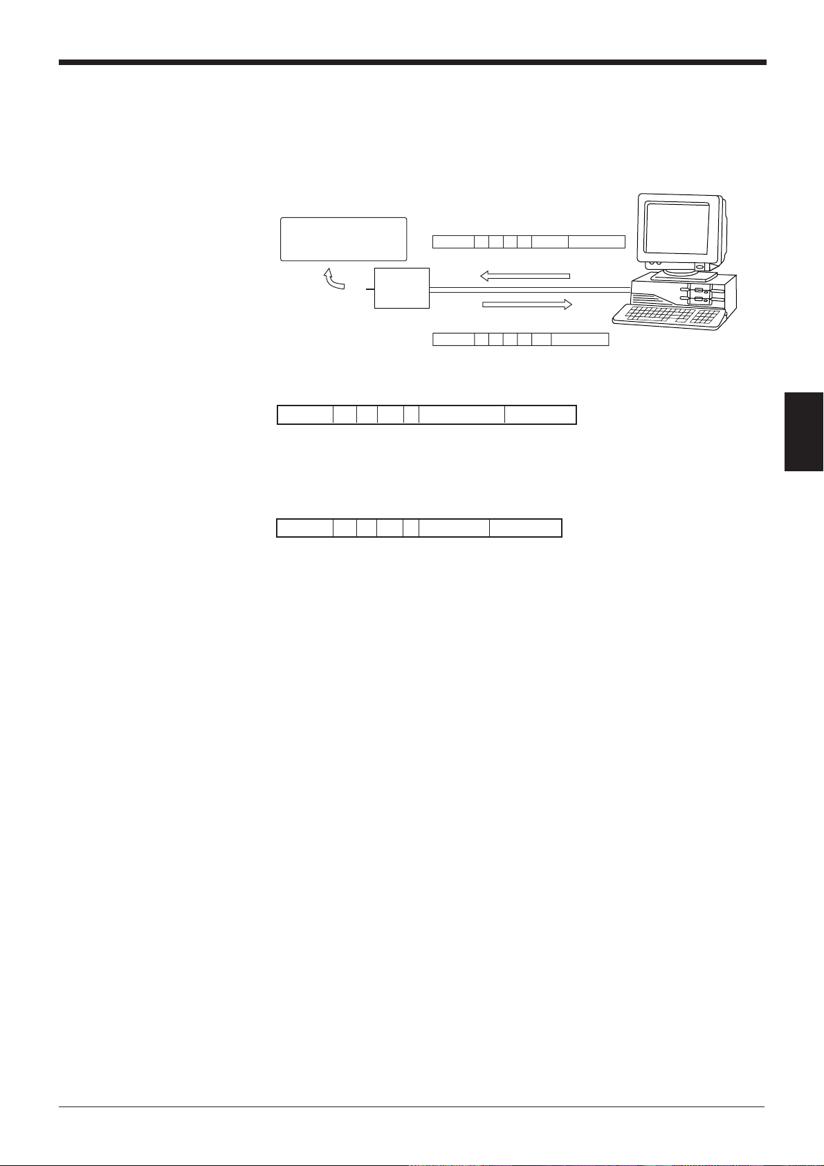
Chapter 4 Multi-Drop Link Mode Control Procedure
4.3 Command Transmission To BL Series
All the serial commands that can be used for the BL series can be sent from the
host computer through the N-400 to the BL series. Send these commands in the
following sequence and format:
The BL series with ID No. 3
starts the reading rate
measurement test mode.
• • •
N-400
1. Send a command in the following format from the host computer.
Header % T 03 – TEST1 Terminator
Header % T 03 – OK Terminator
Header % T mm –
2. When the command is received by the BL series, the BL series sends back a
response in the following format:
Header % T mm – Terminator Response
• mm = 01 to 31: ID number of BL series
• (Response) = Response to the command (“OK”, “ERROR”, etc.)
NC: “Disconnection” error. This error occurs when the BL series with the speci-
fied ID number does not exist.
SERR: Communication error
* For the serial commands, the response to the serial commands, and the error
codes, see the BL series User’s Manual. The BL series does not send any
response to some of the direct control commands (TEST1, LON, etc.). However, the BL series always send back a response when they are used in multidrop link mode.
Serial command
Terminator
4
• OK: Normal processing
• ERR00: Incorrect command
67
Page 76

Chapter 4 Multi-Drop Link Mode Control Procedure
•When the command format is [Command] [CR], the response format is [Re-
sponse] [CR]. When the command format is [STX][Command][ETX], the
response format is [STX][Response][ETX].
Command Response
Command CR Response CR
STX Command ETX STX Response ETX
* [LF] can be added to the end of the command. However, [LF] is not added to
the response.
*When [ESC] is added to the head of the command, the N-400’s receiving buffer
is cleared. However, [ESC] is not added to the response.
Example: Sending “LON” to start reading the BL series with ID No. 5
4
Command being sent:
Response:
Command being sent:
Response:
Note: When the reading rate check mode (TEST1) start command is sent to the BL
series, the data is stored in the BL series’ buffer, causing the buffer overflow error,
unless auto polling is performed.
Even if auto polling is performed, the buffer overflow error may occur because the
polling interval is longer than the BL series’ reading interval when many BL series
are connected. In this case, send the “Specific ID polling ON” command to the N400 (
➮
see p. 72
for the BL series to be tested.
After using the specific ID polling mode, be sure to reset this command.
%T05– OK CR
STX% T 05 – OK ETX
) to control the N-400 directly so that auto polling is performed only
%T05–LON CR
ESCSTX % T 05 – LON ETX
68
Page 77
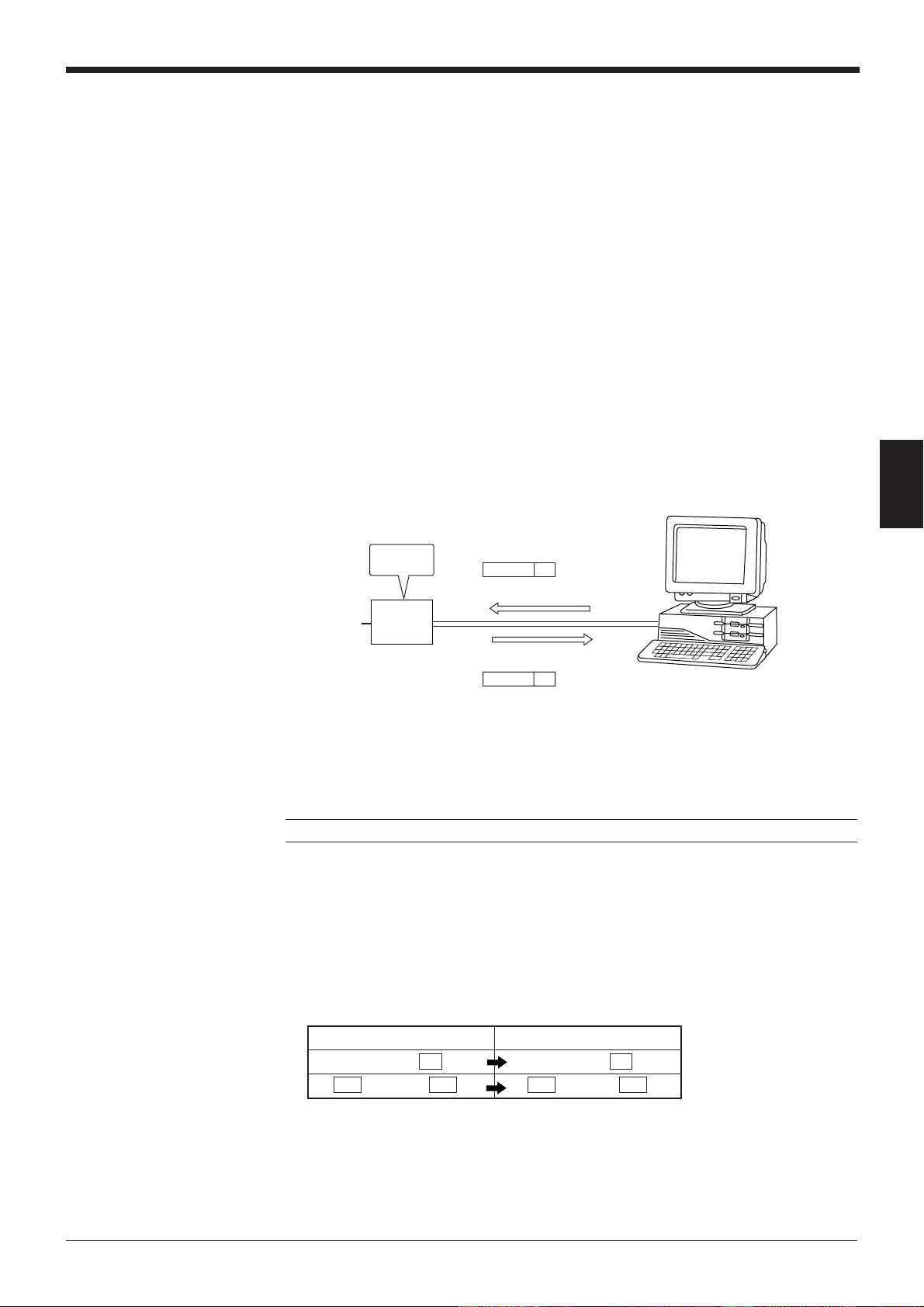
Chapter 4 Multi-Drop Link Mode Control Procedure
4.4 N-400 Direct Control Commands
You can perform the following controls by sending a command to the N-400.
1) Assigning an ID number to the BL series for which auto polling is performed.
2) Setting auto polling mode to ON/OFF
3) Checking if the BL series is properly connected
4) Reading control command in multi-head scan mode
5) Resetting the N-400
The above control 1) can be set with the N-400 setup software. (
above control 3) can be performed using the connection test switch provided on the
N-400. (
➮
See p. 51.
4.4.1 Communication procedure
■ Sequence and format for communication
Auto
ON
• • •
N-400
1. Send a direct control command to the N-400 from the host computer.
2. After the N-400 receives the command, the N-400 sends back a response (e.g.
“OK” or “NG”) to the host computer.
polling
➮
See p. 42.
)
) The
4
POLE00 CR
OK CR
(For a description of the commands, see the following pages.)
Note: If an incorrect command is sent, the N-400 sends back no response.
The ID number is not specified in the command/response format.
The N-400 returns the response with the same header and delimieter as it
receives.
When the command format is [Command][CR], the response format is
[Response][CR]. When the command format is [STX][Command][ETX], the
response format is [STX][Response][ETX].
Command Response
Command CR Response CR
STX Command ETX STX Response ETX
* [LF] can be added to the end of the command. However, [LF] is not added to
the response.
*When [ESC] is added to the head of the command, the N-400’s receiving buffer
is cleared. However, [ESC] is not added to the response.
69
Page 78

Chapter 4 Multi-Drop Link Mode Control Procedure
Example: When the “Polling ON” command is sent to the N-400
When “POLE00 [CR]” is sent to the N-400, the response is “OK [CR]”.
When “[STX] POLE00 [ETX]” is sent to the N-400, the response is “[STX]
OK [ETX]”.
When “[ESC] POLE00 [CR]” is sent to the N-400, the response is “OK
[CR].”
4.4.2 Description of commands
The following is a description of each command.
Registering and checking the ID numbers of the BL series
for which auto polling is performed.
Registers ID numbers for auto polling and checks which ID numbers are registered.
* The following commands are intended for the N-400. These commands do not
4
check whether the BL series of the registered ID number is connected.
● Registering all ID numbers
Command: ID00nnnnn...
n = 0: Do not register
n = 1: Register
Response: OK
ERR07... :“n” is any value other than “0” or “1”.
Description:
“n” corresponds to the ID number (1 to 31) in ascending order. (Thirty-one “n”s
are required.) If you need to register ID numbers 2, 3 and 4, the command is
ID000111000.....
● Checking all ID numbers
Command: IDCHK
Response: nnnnn...
n = 0: Not registered
n = 1: Registered
Description:
“n” corresponds to the ID number (1 to 31) in ascending order. (Thirty-one “n”s
are required.)
70
● Registering individual ID number
Command: IDmmn...
mm = 01 to 31 (ID number)
n = 0: Do not register
n = 1: Register
Response: OK
ERR01...: “mm” exceeds the range of “01” to “31”.
ERR07: “n” is any value other than “0” or “1”.
Page 79

Chapter 4 Multi-Drop Link Mode Control Procedure
● Checking individual ID number
Command: IDCHKmm
[mm = 01 to 31 (ID number)]
Response:
ON: Registered
OFF: Not registered
ERR01: “mm” exceeds the range of “01” to “31”.
● Registering serial ID numbers
Command: IDMAXmm
[mm = 01 to 31 (ID number)]
Response: OK
ERR01: “mm” exceeds the range of “01” to “31”.
Description: Registers all ID numbers not more than “mm”.
When “mm” is “00”, registering serial numbers is disabled.
● Checking serial ID numbers
Command: IDMAX
4
Saving registered ID numbers
The registered ID numbers for auto polling are saved in the N-400.
Controlling auto polling
Setting auto polling mode to ON or OFF.
● Auto polling ON
Response: MAXmm
mm = 01 to 31 (ID number)
mm = 00 : Not registered
mm = 99: The registered ID numbers are not serial numbers.
Description:
Registers all ID numbers not more than “mm”.
When the registered ID numbers are not serial numbers, the response is “99”.
Command: IDSAVE
Response: OK
Command: POLE00
Response: OK
Example: Sending the command to start auto polling (When ten BL series units are
connected)
1. Send “ID001111111111000000000000000000000 [CR]” (or “IDMAX10 [CR]”).
2. The N-400 sends back “OK [CR]”.
3. Send “POLE00 [CR].”
4. The N-400 sends back “OK [CR]”.
71
Page 80

Chapter 4 Multi-Drop Link Mode Control Procedure
● Specific ID polling ON
Command: POLEmm
[mm = 01 to 31 (ID number)]
Response: OK
ERR01: “mm” exceeds the range of “01” to “31”.
The “Specific ID polling ON” command is used to execute polling for the BL
series with the specified ID number only.
When the N-400 executes polling for several BL series in reading rate check
mode, a large amount of data is continuously sent from the BL series, which
causes the buffer overflow error because the polling interval is longer than the
reading interval.
To perform the reading rate check, use the “Specific ID polling ON” command.
● Checking auto polling
Command: POLE
Response: mm OFF
mm = 01 to 31 (ID number)
4
Auto polling is performed for the BL series specified by “IDmm” only.
mm = 00: Auto polling ON
OFF: Auto polling OFF
● Auto polling OFF
Command: POFF
Response: OK
Checking connections in multi-drop link mode
Checks if the RS-485 communication between the N-400 and each BL series is
normal.
Command: SRCmm
[mm = 01 to 31 (ID number)]
Response:
OK: Connection is correct.
NC: “Disconnection” error
SERR: Communication error
ERR01: “mm” exceeds the range of “01” to “31”.
Controlling reading operation
Used to activate the reading trigger signal using a command in multi-head scan
mode.
* This command can be used in multi-head scan mode only.
● Starting reading
Command: LON
Response: None
72
● Ending reading
Command: LOFF
Response: None
You can start/end reading operation by sending the above command in the
same way as when using trigger input.
These commands can be used in multi-head mode only.
Page 81

• The “LON” command corresponds to “Trigger input: ON”, and the “LOFF”
•When the bar code data read by the BL series has already been sent to the
• These commands can be changed to any string of up to eight characters.
Reset
Resets the data stored in the N-400.
Clearing transmission buffer
Clears the transmission buffer of the N-400 and all BL series.
Checking trigger input status
Chapter 4 Multi-Drop Link Mode Control Procedure
command corresponds to “Trigger input: OFF”.
host computer, you do not need to send the “LOFF” command (in “Single Label”
reading mode only).
Command: RESET
Response: OK
Command: BCLR
Response: OK
4
Used to monitor the ON/OFF status of the trigger input connected to the N-400.
* This command can be used in multi-head scan mode only.
Command: TIMCHK
Response: ON OFF
Shift to SETUP mode
Used to go to the SETUP mode. (See p. 4-19.)
Command: SSET
Response: OK
Specifying the ID number of command transmission destination (Hotline command)
Normally, when a command is sent to the BL series, the ID number of the BL
series is added to the command.
If you send the following command, you can send a command to the specified BL
series without adding its ID number to the command.
After using this command, be sure to reset it.
● Specifying the Destination ID number for command transmission
Command: TRCIMmm
[mm = 01 to 31 (ID number)]
Response: OK
ERR01: “mm” exceeds the range of “01” to “31”.
● Resetting the destination ID number for command transmission
Command: TROFF
Response: OK
73
Page 82

Chapter 4 Multi-Drop Link Mode Control Procedure
● Checking the destination ID number for command transmission
Command: TRCOM
Response: mm
[mm = 01 to 31 (ID number)
mm = 00: ID number is not specified.]
■ Description of the procedure
1. Send the “TRCOMmm” command. (The N-400 sends back “OK”.)
The N-400 displays the specified ID number.
2. You can then send a command to the specified BL series without adding its ID
number.
(For the commands sent to the BL series, see the BL series User’s Manual.)
Example
• To start reading: Send “LON [CR]”.
• To end reading: Send “LOFF [CR]”.
• To go to the SETUP mode: Send “SSET [CR]”.
4
3. When the N-400 fails to send a command to the BL series, the BL series sends
back the following response:
NC: The BL series with the specified ID number is disconnected.
SERR: Communication error
4. After the command transmission is completed, be sure to send “TROFF”.
Otherwise, the N-400 cannot receive any commands.
74
Page 83

4.5 N-400 Setup Command
This section describes the procedure for changing the N-400’s settings by sending
a command to the N-400.
To change the settings of the N-400, you should normally use the N-400 setup
software instead of these commands.
■ Details of the communication
1. Send the “SSET” direct control command to the N-400.
The N-400 then goes into SETUP mode. (In SETUP mode, the N-400 displays
“S1(51)”.)
When this command is processed normally, the N-400 sends back “OK”.
2. After the N-400 goes into SETUP mode, send the command of the item to be
changed (setting change command) to the N-400.
When this command is processed normally, the N-400 sends back “OK”.
If an error occurs, the N-400 sends back “ERR**”. (** is the error code.)
Chapter 4 Multi-Drop Link Mode Control Procedure
3. To confirm the N-400’s current settings, send the setting check command to the
N-400.
When this command is processed normally, the N-400 sends back the data on
the current settings.
If an error occurs, the N-400 sends back “ERR**”.(** is the error code.)
4. To save the settings in the EEPROM of the N-400, send the “SAVE” command
to the N-400.
If updated settings are saved in the EEPROM, these settings take effect the
next time the N-400 is turned ON.
When this command is processed normally, the N-400 sends back “OK”.
If an error occurs, the N-400 sends back “ERR**”. (** is the error code.)
5. To exit SETUP mode and perform normal reading operation, send the “SEND”
command to the N-400.
When this command is processed normally, the N-400 sends back “OK”.
If an error occurs, the N-400 sends back “ERR**”. (** is the error code.)
■ Communication format
The ID number is not specified in the command/response format.
The N-400 returns the response with the same header and delimieter as it
receives.
4
When the command format is [Command][CR], the response format is
[Response][CR]. When the command format is [STX][Command][ETX], the
response format is [STX][Response][ETX].
Command Response
Command CR Response CR
STX Command ETX STX Response ETX
* [LF] can be added to the end of the command. However, [LF] is not added to
the response.
*When [ESC] is added to the head of the command, the N-400’s receiving buffer
is cleared. However, [ESC] is not added to the response.
75
Page 84

Chapter 4 Multi-Drop Link Mode Control Procedure
■ Response error codes
If an incorrect setup command is sent to the N-400, the N-400 sends back the
cause of the error (error code).
Error response: ERR** (** is the error code.)
Error code Cause of error
00 Undefined command
01 The ID number exceeds the setting range.
02 The number included in the command does not correspond to anything.
05 The number included in the command is too long.
06 “hhh...” is too short.
07 “N” is any value other than “0” or “1”.
08 “n” exceeds the setting range.
4
09 “nnn” or “nn” exceeds the setting range.
10 “hhh...” is not specified as HEX codes (hexadecimal numbers).
11 Setting “hhh... = FF” is impossible.
12 “hhh...” exceeds the specified number of characters.
14 The data stored in the EEPROM may be corrupted. Initialize the settings.
15 The area storing the initial settings is incorrect.
76
Page 85

Description of setup commands
■ Saving settings/Initializing settings/Quitting SETUP mode
Function Command Response Description Error code
Saving settings SAVE OK See p. 74. 00, 02,
in the EEPROM 05, 14
Initializing DFLT OK Resets the current settings 00, 02,
settings to the default values and 05, 14,
Quitting SEND OK See p. 74. 00, 02,
SETUP mode 05, 14
■ HOST MODE
Chapter 4 Multi-Drop Link Mode Control Procedure
saves them in the EEPROM. 15
Function
Mode
Interference
suppression
Trigger
ON time in
interference
suppression
mode
Read mode
Data transmission timing
(Effective in
signal label
mode only)
Read error
code
Command
Change
Confirm RP00 00n
Change
Change WP47nnn
Confirm
Change
Confirm RP12 12n
Change
Confirm RP13
Change
Confirm RP55
WP00n
WP06n
RP06Confirm 06n
RP47
WP12n
WP13n OK
WP55hhh..
Response
OK
OK
OK
47nnn
OK
13n
OK
55hhh..
Description
n = 0: Multi-drop link
n = 1: Multi-head scan
mode
n = 0: Disable
n = 1: Enable
nnn = 001 to 255
(Units: 10 ms)
n = 0: Single
n = 1: Multi-label 1
n = 2: Multi-label 2
n = 0: After read
n = 1: At trigger
hhh... = Read error code
(up to eight characters)
* To set a read error code,
use HEX (hexadecimal)
codes.
* hhh... = FF: Read error
code is not set.
Error code
00, 02,
05, 07,
14
4
00, 02,
05, 07,
09, 14
00, 02,
05, 08,
14
00, 02,
05, 07,
14
00, 02,
05, 10,
12, 14
Tips
To set a read error code, use the following command format.
Example: To set the read error code to “BR”
B R
WP554252 * B = 42h, R = 52h
77
Page 86

Chapter 4 Multi-Drop Link Mode Control Procedure
■ TRIGGER INPUT SETUP (Effective in multi-head scan mode only)
4
Function
Trigger
input signal
type
One-shot
input time
Trigger
input
time
State of
trigger input
Characters of
trigger ON
command
Change
Characters of
trigger OFF
command
Command
Change
Confirm RP05 05n
Change
Change WP04n
Confirm
Change
Confirm RP03 03n
WP56hhh...
Confirm RP56
Change
Confirm 57hhh..
WP05n
WP42nnn
RP42Confirm 42nnn
RP04
WP03n
OK hhh... =
WP57hhh..
Response
OK
OK
OK
04n
OK
56hhh...
OK
Description
n = 0: Level
n = 1: One-shot
nnn = 001 to 255
(Units: 100 ms)
n = 0: 2 ms
n = 1: 10 ms
n = 0: Normally open
n = 1: Normally closed
Trigger ON command
(up to eight characters)
* To set this command,
use HEX (hexadecimal)
codes.
hhh... = Trigger OFF
command (up to eight
characters)
* To set this command,
use HEX (hexadecimal)
codes.
Error code
00, 02,
05, 07,
14
00, 02,
05, 07,
09, 14
00, 02,
05, 07,
14
00, 02,
05, 06,
11, 14
00, 02,
05, 06,
11, 14
Tips
To set the characters of the trigger ON/OFF commands, use the following command format:
Example: To change the trigger ON command to “[CR]” or “[STX]S[ETX]”.
S
WP5653 * S = 53h
78
Page 87

■ PROTOCOL SETUP
Chapter 4 Multi-Drop Link Mode Control Procedure
Function
Handshaking
protocol 1
Handshaking
protocol 2
Header
Delimiter
Adding
checksum
Command
Change
Confirm RP07 07n
Change OK
Change
Confirm RP51
Change
Confirm
Change WP39n OK
Confirm
WP07n
WP08n
WP51hhh...
WP52hhh...
R39 39n
RP39 39n
Response
OK
08n
OK
51hhh...
OK
Description
n = 0: No handshaking
n = 1: Use protocol
*To set details of the
protocol, use
handshaking protocol 2.
n = 0: PASS/RTRY
protocol
n = 1: ACK/NAK protocolRP08Confirm
hhh... = Header (up to
five characters)
* To set a header, use
HEX (hexadecimal)
codes.
* hhh... = FF: Header is
not set.
hhh... = Delimiter (up to
five characters)
* To set a delimiter, use
HEX (hexadecimal)
codes.
* hhh... = FF: Delimiter is
not set.
n = 0: Do not add
n = 1: Add
Error code
00, 02,
05, 07,
14
00, 02,
05, 10,
12, 14
4
00, 02,
05, 07,
14
79
Page 88

Chapter 4 Multi-Drop Link Mode Control Procedure
■ PROTOCOL SETUP (only when PLC link is used)
4
Function
PLC link model
Trigger input
through PLC
link
DM head
address
PLC / station
number
File register
block number
Command
Change
Confirm
Change
Confirm
Change
Confirm
Change
Confirm
Change
Confirm RP41 41nnn
WP36n
RP36
WP37n
RP37
WP40nn
RP40
WP43nn OK
RP43
WP41nnn
Response
OK
36n
OK
37n
OK
40nn
43nn
OK
Description
n = 0: PLC link disabled
n = 1: SYSNAC-C
n = 2: MELSEC-A
n = 3: KV
n = 4: MELSEC-A (File
register is used.)
n = 0: Disable
n = 1: Enable
nn = 00 to 99
(0000 to 9900)
nn = 00 to 31
nnn = 000 to 255
Error code
00, 02,
05, 08,
14
00, 02,
05, 07,
14
00, 02,
05, 07,
09, 14
80
Page 89

■ ID SETUP
Chapter 4 Multi-Drop Link Mode Control Procedure
Function
Registering ID
number (for
each unit)
Registering
serial numbers
(Register all ID
numbers more
than the
specified
number.)
Registering all
serial numbers
Command
Change
Confirm
Change
Confirm
Change
Confirm
■ RS-232C SETUP
Response
WIDmmn
RIDmm
WIDMAXmm
RWIDMAXmm
WIDAnnn...n OK
RIDA
OK
mmn
OK
MAXmm
Annn...n
Description
mm = 01 to 31 (ID 3
number)
n = 0: Do not register
n = 1: Register
mm = 01 to 31 (ID 4
number)
* If “mm” is “99” in the
response, serial ID
numbers are not
registered.
n = 0: Do not register
n = 1: Register
* “n” corresponds to ID
numbers (1 to 31) in
ascending order.
Error code
00, 01,
02, 05,
07, 14
00, 01,
02, 05,
14
00, 02,
05, 07,
14
4
Function
Baud rate
Data length
Parity Change
Parity type
Stop bit length
Command
Change
Confirm
Change
Confirm
Confirm RP31
Change WP32n
Confirm RP32 32n
Confirm
Response
WP35n OK
RP35
WP30n
RP30
WP31n OK
WP33nChange OK
RP33 33n
35n
OK
30n
31n
OK n = 0: Even
Description
n = 5: 38400 bps
n = 6: 31250 bps
n = 7: 19200 bps
n = 0: 9600 bps
n = 1: 4800 bps
n = 2: 2400 bps
n = 3: 1200 bps
n = 4: 600 bps
n = 0: 7 bits
n = 1: 8 bits
n = 0: None
n = 1: Set parity
* To set the parity type,
use the "Parity type"
command.
n = 1: Odd
n = 0: 1 bit
n = 1: 2 bits
Error code
00, 02,
05, 08,
14
00, 02,
05, 07,
14
RTS/CTS
control
Change WP22n OK n = 0: Disable
Confirm RP322 22n
n = 1: Enable
81
Page 90

Chapter 4 Multi-Drop Link Mode Control Procedure
■ RS-485 SETUP
4
Function
Baud rate
Data length
Parity Change
Parity type
Stop bit length
Command
Change
Confirm
Change
Confirm
Confirm RP71
Change WP72n
Confirm RP72 72n
Confirm
Response
WP75n OK
RP75
WP70n
RP70
WP71n OK
WP73nChange OK
RP73 73n
75n
OK
70n
71n
OK n = 0: Even
Description
n = 5: 38400 bps
n = 6: 31250 bps
n = 7: 19200 bps
n = 0: 9600 bps
n = 1: 4800 bps
n = 2: 2400 bps
n = 3: 1200 bps
n = 4: 600 bps
n = 0: 7 bits
n = 1: 8 bits
n = 0: None
n = 1: Set parity
* To set the parity type,
use the "Parity type"
command.
n = 1: Odd
n = 0: 1 bit
n = 1: 2 bits
Error code
00, 02,
05, 08,
14
00, 02,
05, 07,
14
82
Page 91

Chapter 4 Multi-Drop Link Mode Control Procedure
N400
(RS-485)
BL
N400
(RS-232C)
Host
123 1234451123 23455
b a
AA
BB
4.6 Communication Time Consideration
This section describes how to calculate the time required for data transmission and
for command transmission in multi-drop link mode.
■ How to calculate data transmission time
The following is the timing chart for multi-drop link mode communication .
Through the RS-485 communication between the N-400 and each BL series unit,
data transmission is constantly performed from the BL series to the N-400.
When the N-400 sends the polling command to a BL series with a specified ID
number, the data read by the BL series is sent to the host computer through the
RS-232C interface of the N-400.
4
* The above timing chart shows the case in which five BL series units are con-
nected.
Therefore, data transmission is delayed by a certain time duration until the polling
command is sent to the BL series after the BL series reads bar code data.
First, obtain the time duration required for the RS-485 data transmission.
In the RS-485 data transmission from the BL series to the N-400, the required time
varies depending on whether the BL series has stored bar code data (the BL series
has already read bar code data) or not.
In the above timing chart, “a” (the RS-485 data transmission time is short) shows
the case in which the BL series has stored no data, and “b” (the RS-485 data
transmission time is long) shows the case in which the BL series has stored some
data.
• a: RS-485 data transmission time required when the BL series has stored no
data
Baud rate (for RS-485) Communication time (a)
9600 bps 27.9 ms
38400 bps 12.8 ms
• b: RS-485 data transmission time required when the BL series has stored some
data
Baud rate (for RS-485) Communication time (b)
Number of data Number of data Number of data
digits: 10 digits: 20 digits: 32
9600 bps 64 ms 74 ms 86 ms
38400 bps 28 ms 32 ms 37 ms
83
Page 92

Chapter 4 Multi-Drop Link Mode Control Procedure
From the above data, the RS-485 data transmission time (“A” shown in the timing
chart on the previous page) is obtained as follows:
• Maximum time: A = a x n + b (n = Number of connected BL series)
• Minimum time: A = b
* The above table shows the case in which one BL series sends data to the N-
400. When several BL series simultaneously send data, the required time may
be longer than the above.
The time duration “b” (corresponding to the case in which the BL series has
stored some data) is prolonged.
Next, obtain the time duration required for the RS-232C data transmission.
The RS-232C data transmission time (“B” shown in the timing chart on the previous
page) can be obtained from the following formula:
Amount of data + (1: Set Parity) + Start/Stop bit
B =
Baud rate
x
(Number of data digits + Header/Delimiter + 5)
4
Baud rate (for RS-232C) Communication time (b)
Number of data Number of data Number of data
digits: 10 digits: 20 digits: 32
9600 bps 21.3 ms 33.8 ms 48.8 ms
38400 bps 5.4 ms 8.5 ms 12.2 ms
From the above data, the total communication time is obtained as follows:
Communication time = A + B
■ Command communication time
When you send a command (e.g. Laser ON command) to the BL series, obtain the
time duration for how long it takes for the BL series to receive the command after
you send it to the N-400.
The communication time required to send a command to the BL series consists of
the time required for the RS-232C command transmission from the host computer
to the N-400, and the time required for the RS-485 command transmission from the
N-400 to each BL series.
However, since each BL series constantly sends its data to the N400, the command transmission from the N-400 to the BL series must be performed in the
interval of the data transmission from the BL series to the N-400.
84
N-400
(RS-485)
Host
(RS-232C)
BL
N-400
a b
123 142
C
Command Command
Command Command
E E
3551235144
D
D
C
First, obtain the time (C) required for the RS-232C command transmission from the
host computer to the N-400. Calculate this time duration by substituting the number
of command characters (e.g. LON: three characters, LOFF: four characters) for the
number of data digits in formula B given above.
Page 93

Chapter 4 Multi-Drop Link Mode Control Procedure
Baud rate (for RS-232C) Communication time (B)
Command = LON Command = LOFF
9600 bp 12.5 ms 13.8 ms
38400 bps 3.2 ms 3.5 ms
Then, obtain the time duration (D) required for the RS-485 command transmission
from the N-400 to the BL series. When the reading start command (LON) or reading end command (LOFF) is sent to the BL series, for example, the communication
time is as follows:
Baud rate (for RS-485) Communication time (D)
Command = LON Command = LOFF
9600 bp 29 ms 30 ms
38400 bps 11.5 ms 11.8 ms
From the above data, the total communication time (E) can be obtained as follows:
Maximum time: E = C + b + D
* b: Time required for the data transmission from the BL series to the N-400 when
the BL series has stored some data
Minimum time: E = C + D
4
85
Page 94

Chapter 4 Multi-Drop Link Mode Control Procedure
4
86
Page 95

Chapter 5
Multi-Head Mode Control Procedure
5.1 Multi-head Mode .................................................................88
5.1.1 Controlling multi-head mode..................................................88
5.1.2 Setup procedure ....................................................................89
5.2 Reading Operation in Multi-Head Mode ............................91
5.2.1 Difference in operation depending on reading mode.............91
5.2.2 Trigger input signal type ........................................................93
5.2.3 Data transmission timing .......................................................94
5.3 Data Communication in Multi-Head Mode ........................95
5.3.1 Communication format...........................................................95
5.3.2 Handshaking protocol ............................................................95
5.3.3 Read error code.....................................................................95
5.4 Command Communication in Multi-Head Mode ..............96
5.4.1 Sending a command to BL series..........................................96
5.4.2 N-400 direct control/setup commands ...................................96
5.5 Interference Suppression Function ..................................97
5.6 Communication Time .........................................................98
Page 96
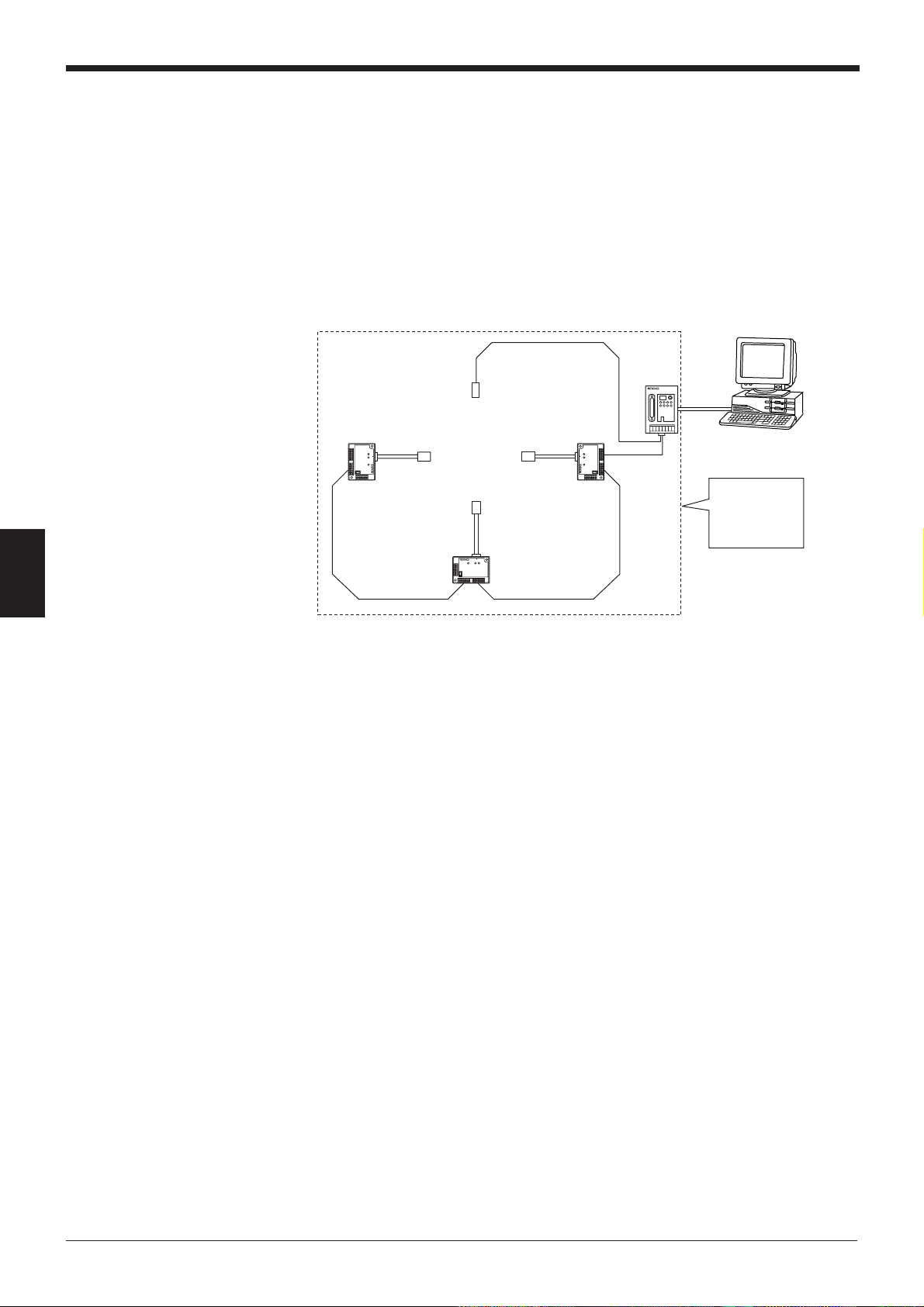
Chapter 5 Multi-Head Mode Control Procedure
N-400
RS-232C
RS-485
Host PC
Sensor for
trigger input
*
N-48
or
BL-U1
The host
computer can
control several BL
series like it would
be a single unit.
5.1 Multi-head Mode
5.1.1 Controlling multi-head mode
If the bar code position on a product is unknown, or if bar codes are printed in
several positions, the bar code data cannot be read with a single bar code reader.
In such cases, several bar code readers need to be mounted in various positions or
at various angles.
When the N-400 is used in multi-head mode, the host computer can control several
BL series like it would be a single unit.
5
The procedures for controlling the N-400 using the host computer are classified
into the following three methods:
• Data communication: Used to send bar code data read by the BL series to the
host computer.
• Command communication to the BL series: Used to send a command to the BL
series.
• Command communication to the N-400: Used to control the N-400 directly or
change the settings of the N-400.
* All of the above communication methods use ASCII codes.
The procedures for sending a command to the BL series or the N-400 are the
same as for multi-drop link mode. For details, see the descriptions on multi-drop
link mode.
88
Page 97

5.1.2 Setup procedure
For setup and connection procedures, see p. 10. This section describes the
procedures for setting the N-400, BL series and host computer only.
Setting the BL series
1. Set “Multi-drop Link” to “Enable”. (Click the button.)
2. Assign ID numbers (1 to 31) to the connected BL series. Be sure not to
3. Set the RS-485 communication parameters (baud rate, data length,
Note: To increase the response speed, set the BL series’ baud rate to
38400 bps.
Chapter 5 Multi-Head Mode Control Procedure
assign the same ID number to different units.
parity and stop bit length) for the BL series according to the N-400’s
settings. The default settings for the BL series and the N-400 are as
follows:
Baud rate: 9600 bps
Data length: 7 bits
Parity: Even
Stop bit length: 1 bit
4. Setting “Handshaking protocol” or “RTS/CTS” is not effective.
5. Set “Header” to “None”. Setting the terminator is not effective.
6. Set the BL series’ reading mode to “Single label”.
7. Set the trigger input signal type to “Level”.
8. Set the read error code of the BL series according to the N400’s setting.
Normally, the read error code is set to “ERROR” (default setting).
9. Set the reading start command and read end commands according to
the N-400’s settings. Normally, these commands are set to “LON” and
”LOFF” respectively (default settings).
* Set other parameters as required.
5
89
Page 98

Chapter 5 Multi-Head Mode Control Procedure
Setting the N-400
Using the N-400 setup software, set the N-400 as follows:
5
1. Set the host mode to multi-head mode (Click the button). (
2. In multi-head mode, connect the trigger input to the N-400 so that all BL series
connected to the N-400 are controlled as if they are a single bar code reader.
You must set the “Read mode” and “Trigger input signal type” of the N-400.
3. Enter the ID numbers of the connected BL series on the “ID SETUP” screen.
(
➮
See p. 42.
4. Set the baud rate, data length, parity and stop bit length according to the host
computer’s settings on the “RS-232C SETUP” screen. (
5. Set the baud rate, data length, parity and stop bit length according to the BL
series’ settings on the “RS-485 SETUP” screen. (
Note: To increase the response speed, set the RS-485 communication baud rate
to 38400 bps. (Set the BL series’ baud rate to this value as well.)
6. Set the read error code of the N-400 according to the BL series’ setting. Normally, the read error code is set to “ERROR” (default setting).
7. Set the reading start command and read end commands according to the BL
series’ settings. Normally, these commands are set to “LON” and ”LOFF”
respectively (default settings).
)
➮
➮
➮
See p. 42.
See p. 43.
See p. 38.
)
)
)
Setting the host computer
Set the RS-232C communication parameters (baud rate, data length, parity and
stop bit length) for the host computer according to the N-400’s settings.
90
Page 99
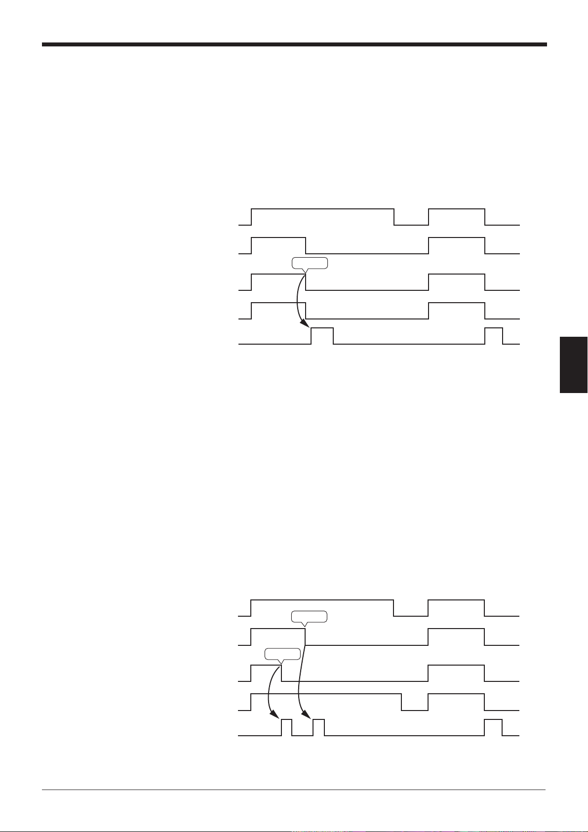
Chapter 5 Multi-Head Mode Control Procedure
5.2 Reading Operation in Multi-Head Mode
5.2.1 Difference in operation depending on reading mode
Multi-head mode can control several BL series like they are a single bar code
reader. The N-400 provides the “Level” and “Oneshot” trigger signal types, and the
“Single” label and “Multi” label reading modes.
“Single” label reading mode
The following timing chart shows the case in which three BL series are connected.
Timing input
Light source of
BL series with
ID No. 1
Light source of
BL series with
ID No. 2
Light source of
BL series with
ID No. 3
Reading
• In the “Single” label reading mode, a piece of data which was first read by any
• If all of the connected BL series units cannot read bar code data while the
• Normally, the BL series sends data immediately after reading it. However, you
“Multi 1” label reading mode
The following timing chart shows the case in which three BL series are connected.
Communication
output
* A piece of data which was read
first is sent.
* Read error
of several BL series is sent to the host computer. (When any of the connected
BL series reads bar code data, all light sources of the other BL series are turned
OFF.) Therefore, several BL series can be operated like a single bar code
reader.
trigger input is ON, a read error code is output.
can set the data transmission timing so that data is sent after the trigger input is
turned OFF. (
Timing input
➮
See p. 94.
)
Reading
5
Light source of
BL series with
ID No. 1
Light source of
BL series with
ID No. 2
Light source of
BL series with
ID No. 3
Communication
output
Reading
* Data is sent sequentially starting with
the earliest data.
* Read error
91
Page 100

Chapter 5 Multi-Head Mode Control Procedure
Header 1234 Terminator Header ABC Terminator Header ERROR T erminator
Header ERROR Terminator Header ERROR Terminator Header ERROR Terminator
The BL series with ID No. 1
reads bar code data as “1234”.
The BL series with ID No. 2
reads bar code data as “ABC”.
Read error occurred in the BL
series with ID No.3.
Read errors have occurred in the BL series
with ID Nos. 1, 2 and 3.
• In “Multi 1” reading mode, all connected BL series units read bar code data
while the trigger input is ON, and send the individual data immediately after
reading it.
•A BL series that causes a read error sends no data.
• If all of the connected BL series cannot read bar codes while the trigger input is
ON, a read error code is output.
“Multi 2” reading mode
The following timing chart shows the case in which three BL series are connected.
5
Reading
Reading
ID•••
123 123
A B
Timing input
Light source of
BL series with
ID No. 1
Light source of
BL series with
ID No. 2
Light source of
BL series with
ID No. 3
Communication
output
• In “Multi 2” reading mode, all connected BL series read bar code data while the
trigger input is ON, and send the individual data after the trigger input is turned
OFF, starting with the smallest ID number.
• In “Multi 2” reading mode, every connected BL series sends a piece of data. A
BL series which causes a read error sends an error code.
Example: In the above timing chart, the communication output is as follows:
Communication output (A):
Communication output (B):
92
 Loading...