

Page 1
Setting and Support Software LS-H1W
for LS-7600/7000 Series
LS-Navigator
User’s Manual
Read this manual before using the system in order to obtain
full performance.
Keep this manual in a safe place for future reference.
96136E
Page 2
2
Safety Precautions
This manual describes the functions and usage for LS-Navigator, the setting and support software LS-H1W for
LS-7600/7000 series. Read this manual carefully before starting to use the software to ensure the optimum
performance and full functionality of the LS-Navigator. Keep this manual in a safe place for future reference.
Symbols
The following symbols and conventions alert you to important messages.
Symbol Description
WARNING
CAUTION
Note
Reference
Failure to follow instructions may lead to personal injury, such as burns or electric shock.
Failure to follow instructions may lead to product damage.
Provides additional information on proper operations that can be easily mistaken.
Provides advanced and useful information for operation.
General Cautions
• At startup and during operation, be sure to monitor the functions and performance of the software.
•
We recommend that you take substantial safety measures to avoid any damage in the event that a problem occurs.
• Do not modify the product or use it in any way other than described in the specifications.
• When the software is used in combination with other devices, functions and performance may be diminished,
depending on the operating conditions and surrounding environment.
Copyrights
• Windows 7, Vista, Windows XP, Windows 2000 Professional is the registered trademark of Microsoft Corporation, U.S.A.
• Pentium is the registered trademark of Intel Corporation, U.S.A.
• Other company names and product names are registered trademarks or trademarks of the respective companies.
For detailed operations for each controller (LK-7600/7500/7000), see the “User's Manual” for the
controller.
LS-Navigator-M-NO0-J
Page 3

Terms of the Software License Agreement
LS-Navigator is available to you provided that you agree with the following license agreement.
Read the following agreements carefully before using this software.
By using the LS-Navigator, you signify that you agree with the statements herein and the contract is accepted.
License agreement
1. License of use
KEYENCE grants the user the nonexclusive right to use this software in accordance with terms of this agreement.
2. Copyright
The copyright on the software and supplied documentation belong to KEYENCE Corporation. The user holds
only the license for its use.
3. Prohibited matter
The user may not copy this software and sell or distribute it to a third party. However, when using this software on
a computer that is connected to the KEYENCE product that was purchased with this software, this software may
be installed onto multiple computers for the same company. Also, you may copy this software for the purpose of
keeping backup copy for your personal use.
4. Escape clause
KEYENCE Corporation shall not be held liable by the user or a third party for any damages arising from the use
of the software.
5. Cancellation of contract
KEYENCE may terminate this agreement if the user fails to comply with the terms of this agreement. In such
event, the user must either return the software and all copies to KEYENCE or destroy.
LS-Navigator-M-NO0-E
96136E
1
Page 4

MEMO
2
LS-Navigator-M-NO0-E
Page 5
Organization of the Manual
Chapter
1
Chapter
2
Chapter
3
Chapter
4
Chapter
5
Appendix
LS-Navigator
Overview
Getting Started
Names and Functions
of Parts of the Window
Operation Flow from
Startup to Shutdown
Functions and
Operation Procedures
Appendix
This chapter describes the key functions, the conditions for use, and the system
environment for the LS-Navigator.
This chapter describes how to connect the computer and the controller, and how to
install or uninstall LS-Navigator.
This chapter describes the names and functions of each part of the LS-Navigator
window.
This chapter describes the basic flow of operations for the LS-Navigator from startup
to shutdown.
This chapter describes the operation procedures and the functions for each menu in the
LS-Navigator.
This chapter describes error messages and shortcut keys.
1
2
3
4
5
A
LS-Navigator-M-NO0-E
3
Page 6

MEMO
4
LS-Navigator-M-NO0-E
Page 7

Table of Contents
Safety Precautions
Terms of the Software License Agreement. . . . . . . . . . . . . . . . . . . . . . . . . . . . . . . . . . . . . . . . . . . . . . . 1
License agreement . . . . . . . . . . . . . . . . . . . . . . . . . . . . . . . . . . . . . . . . . . . . . . . . . . . . . . . . . . . .1
Organization of the Manual. . . . . . . . . . . . . . . . . . . . . . . . . . . . . . . . . . . . . . . . . . . . . . . . . . . . . . . . . . . 3
Table of Contents . . . . . . . . . . . . . . . . . . . . . . . . . . . . . . . . . . . . . . . . . . . . . . . . . . . . . . . . . . . . . . . . . . 5
Chapter 1 LS-Navigator Overview
1-1 LS-Navigator Overview. . . . . . . . . . . . . . . . . . . . . . . . . . . . . . . . . . . . . . . . . . . . . . . . . . 1-2
Controller program setting function . . . . . . . . . . . . . . . . . . . . . . . . . . . . . . . . . . . . . . . . . . . . . 1-2
Backup and restore functions for all controller settings . . . . . . . . . . . . . . . . . . . . . . . . . . . . . . 1-3
Measurement value monitoring and control function . . . . . . . . . . . . . . . . . . . . . . . . . . . . . . . 1-3
Function for transferring measurement values to an Excel sheet. . . . . . . . . . . . . . . . . . . . . . . 1-4
Setting conditions . . . . . . . . . . . . . . . . . . . . . . . . . . . . . . . . . . . . . . . . . . . . . . . . . . . . . . . . . . . 1-4
1-2 System Environment . . . . . . . . . . . . . . . . . . . . . . . . . . . . . . . . . . . . . . . . . . . . . . . . . . . 1-5
Chapter 2 Getting Started
2-1 Connecting the Controller and the Computer. . . . . . . . . . . . . . . . . . . . . . . . . . . . . . . . . 2-2
Connecting . . . . . . . . . . . . . . . . . . . . . . . . . . . . . . . . . . . . . . . . . . . . . . . . . . . . . . . . . . . . . . . . 2-2
2-2 Installing . . . . . . . . . . . . . . . . . . . . . . . . . . . . . . . . . . . . . . . . . . . . . . . . . . . . . . . . . . . . . 2-3
Example of installation on Windows XP . . . . . . . . . . . . . . . . . . . . . . . . . . . . . . . . . . . . . . . . . 2-3
2-3 Uninstalling . . . . . . . . . . . . . . . . . . . . . . . . . . . . . . . . . . . . . . . . . . . . . . . . . . . . . . . . . . . 2-6
Example of uninstallation on Windows XP . . . . . . . . . . . . . . . . . . . . . . . . . . . . . . . . . . . . . . . 2-6
Chapter 3 Names and Functions of Parts of the Window
3-1 Main Window . . . . . . . . . . . . . . . . . . . . . . . . . . . . . . . . . . . . . . . . . . . . . . . . . . . . . . . . . 3-2
Names and functions of parts of the main window . . . . . . . . . . . . . . . . . . . . . . . . . . . . . . . . . 3-2
3-2 Menu Bar . . . . . . . . . . . . . . . . . . . . . . . . . . . . . . . . . . . . . . . . . . . . . . . . . . . . . . . . . . . . 3-3
Command names and functions for each menu . . . . . . . . . . . . . . . . . . . . . . . . . . . . . . . . . . . . 3-3
3-3 Tool Bar . . . . . . . . . . . . . . . . . . . . . . . . . . . . . . . . . . . . . . . . . . . . . . . . . . . . . . . . . . . . . 3-5
Names and functions of the tools . . . . . . . . . . . . . . . . . . . . . . . . . . . . . . . . . . . . . . . . . . . . . . . 3-5
Chapter 4 Operation Flow from Startup to Shutdown
4-1 Basic Flow of Operations . . . . . . . . . . . . . . . . . . . . . . . . . . . . . . . . . . . . . . . . . . . . . . . . 4-2
4-2 Basic Procedures for Operation . . . . . . . . . . . . . . . . . . . . . . . . . . . . . . . . . . . . . . . . . . . 4-3
LS-Navigator-M-NO0-E
Operation flow from startup to shutdown . . . . . . . . . . . . . . . . . . . . . . . . . . . . . . . . . . . . . . . . 4-2
Basic procedures from startup to shutdown . . . . . . . . . . . . . . . . . . . . . . . . . . . . . . . . . . . . . . . 4-3
5
Page 8

Chapter 5 Operating and Setting Functions
5-1 Setting and Changing the Connection . . . . . . . . . . . . . . . . . . . . . . . . . . . . . . . . . . . . . . 5-2
Setting and changing the connected controller. . . . . . . . . . . . . . . . . . . . . . . . . . . . . . . . . . . . . 5-2
5-2 Reading and Saving Setting Files . . . . . . . . . . . . . . . . . . . . . . . . . . . . . . . . . . . . . . . . . 5-3
Reading setting files . . . . . . . . . . . . . . . . . . . . . . . . . . . . . . . . . . . . . . . . . . . . . . . . . . . . . . . . . 5-3
Saving setting files . . . . . . . . . . . . . . . . . . . . . . . . . . . . . . . . . . . . . . . . . . . . . . . . . . . . . . . . . . 5-4
5-3 Setting and Changing Units . . . . . . . . . . . . . . . . . . . . . . . . . . . . . . . . . . . . . . . . . . . . . . 5-5
5-4 Viewing the Measurement Value . . . . . . . . . . . . . . . . . . . . . . . . . . . . . . . . . . . . . . . . . . 5-6
5-5 Sending, Receiving, and Initializing Settings . . . . . . . . . . . . . . . . . . . . . . . . . . . . . . . . . 5-7
Sending settings . . . . . . . . . . . . . . . . . . . . . . . . . . . . . . . . . . . . . . . . . . . . . . . . . . . . . . . . . . . . 5-7
Receiving settings. . . . . . . . . . . . . . . . . . . . . . . . . . . . . . . . . . . . . . . . . . . . . . . . . . . . . . . . . . . 5-8
Initializing setting parameters . . . . . . . . . . . . . . . . . . . . . . . . . . . . . . . . . . . . . . . . . . . . . . . . . 5-9
5-6 Backing up or Restoring All Settings . . . . . . . . . . . . . . . . . . . . . . . . . . . . . . . . . . . . . . 5-10
Backing up all settings for the controller . . . . . . . . . . . . . . . . . . . . . . . . . . . . . . . . . . . . . . . . 5-10
Restoring all settings for the controller . . . . . . . . . . . . . . . . . . . . . . . . . . . . . . . . . . . . . . . . . 5-11
5-7 Setting RS-232C Communication Conditions. . . . . . . . . . . . . . . . . . . . . . . . . . . . . . . . 5-12
5-8 Verifying and Changing the Program No.. . . . . . . . . . . . . . . . . . . . . . . . . . . . . . . . . . . 5-18
5-9 Transferring the Measurement Values t
5-10 Settin
g the Measurement Conditions for the Program . . . . . . . . . . . . . . . . . . . . . . . . . 5-22
Limits . . . . . . . . . . . . . . . . . . . . . . . . . . . . . . . . . . . . . . . . . . . . . . . . . . . . . . . . . . . . . . . . . . . 5-22
Calibration . . . . . . . . . . . . . . . . . . . . . . . . . . . . . . . . . . . . . . . . . . . . . . . . . . . . . . . . . . . . . . . 5-23
Area settings . . . . . . . . . . . . . . . . . . . . . . . . . . . . . . . . . . . . . . . . . . . . . . . . . . . . . . . . . . . . . . 5-24
Output settings . . . . . . . . . . . . . . . . . . . . . . . . . . . . . . . . . . . . . . . . . . . . . . . . . . . . . . . . . . . . 5-25
Settings list . . . . . . . . . . . . . . . . . . . . . . . . . . . . . . . . . . . . . . . . . . . . . . . . . . . . . . . . . . . . . . . 5-26
o Excel . . . . . . . . . . . . . . . . . . . . . . . . . . . . . . 5-19
Appendix
1. Error Message List . . . . . . . . . . . . . . . . . . . . . . . . . . . . . . . . . . . . . . . . . . . . . . . . . . . . . A-2
During operation. . . . . . . . . . . . . . . . . . . . . . . . . . . . . . . . . . . . . . . . . . . . . . . . . . . . . . . . . . . .A-2
When starting up. . . . . . . . . . . . . . . . . . . . . . . . . . . . . . . . . . . . . . . . . . . . . . . . . . . . . . . . . . . .A-3
General application. . . . . . . . . . . . . . . . . . . . . . . . . . . . . . . . . . . . . . . . . . . . . . . . . . . . . . . . . .A-3
2. Shortcut Key List . . . . . . . . . . . . . . . . . . . . . . . . . . . . . . . . . . . . . . . . . . . . . . . . . . . . . . . A-4
3. Index . . . . . . . . . . . . . . . . . . . . . . . . . . . . . . . . . . . . . . . . . . . . . . . . . . . . . . . . . . . . . . . . A-5
6
LS-Navigator-M-NO0-E
Page 9

1
LS-Navigator Overview
This chapter describes the key functions, the setting conditions,
and the system environment for the LS-Navigator.
1-1 LS-Navigator Overview....................................... 1-2
1-2 System Environment .......................................... 1-5
LS-Navigator-M-NO1-E
1-1
Page 10

1-1 LS-Navigator Overview
This chapter describes the functions and setting conditions for the LS-Navigator.
1
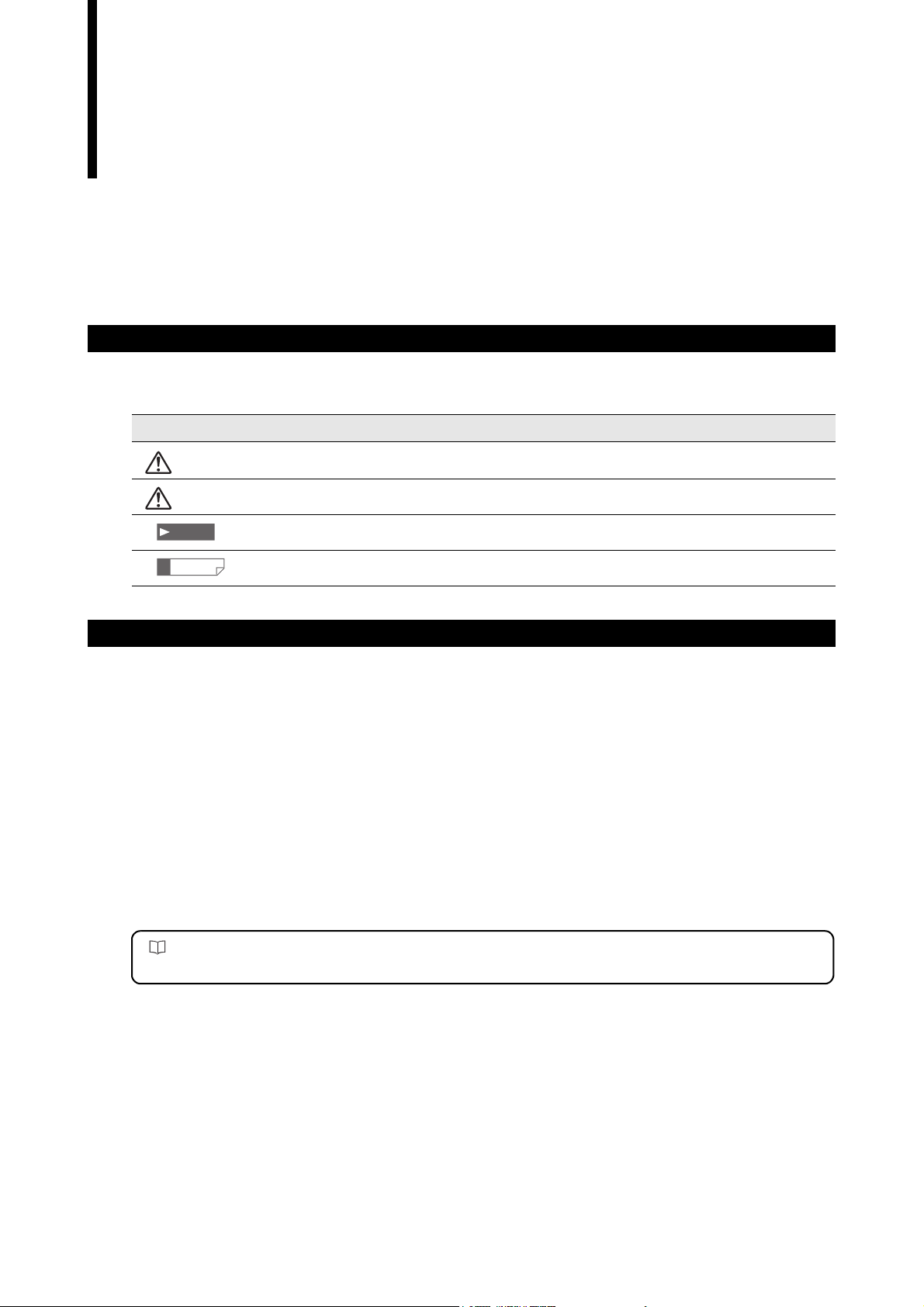
Controller program setting function
1. Receives program settings for the controller on the computer and allows the user to verify the data.
2. Sends settings created on the computer to the controller and sets the program.
3. Reduces the time for settings with copy and paste functions when making settings for multiple controllers or
programs.
The following settings (parameters) for the controller can be verified and changed. Use the controller to change
parameters that are not listed.
Valid parametersDefault values
[OUT1] [OUT2]
[Limit settings]
Limit UPPER 1 1
STA N DA R D 1 0 1 0
LOWER -1 -1
HH 40 40
HI 30 30
LO 0 0
LL -10 -10
HOLD-H ON/OFF OFF OFF
Setting value
HOLD-L ON/OFF OFF OFF
Setting value0 0
00
[Output settings]
Calculation A1 +1 0
A2 0 +1
Averaging times 512 512
Measurement mode NormalNormal
Self-timing time 100 100
Offset 0 0
Analog output Scaling value 1000 1000
+10V = 30 30
-10V = 0 0
[Area 1] [Area 2]
[Area settings]
HeadHead 1 Head 1
Area settings Ar
Edge detection threshold 50 50
[Calibration settings]
Calibration T1-A 0 0
ea DIA DIA
SEG (start
SEG (end) +3E +3E
Area check OFF OFF
T2-A 0 0
T1-B 0 0
T2-B 0 0
) +2E +2E
1-2
LS-Navigator-M-NO1-E
Page 11
1-1 LS-Navigator Overview
Backup and restore functions for all controller settings
1. Reads and backs up the settings for all 16 programs on the controller (all of the parameters for limit settings,
calibration settings, area settings, and output settings) and the environment settings on the computer.
2. Restores the settings from the backup file created on the computer, in the event that the settings are erased
from the controller.
Note
There is no limit to the settings (parameters) that can be backed up or restored for the controller. Even parameters that
cannot be set by the program setting function can be backed up or restored.
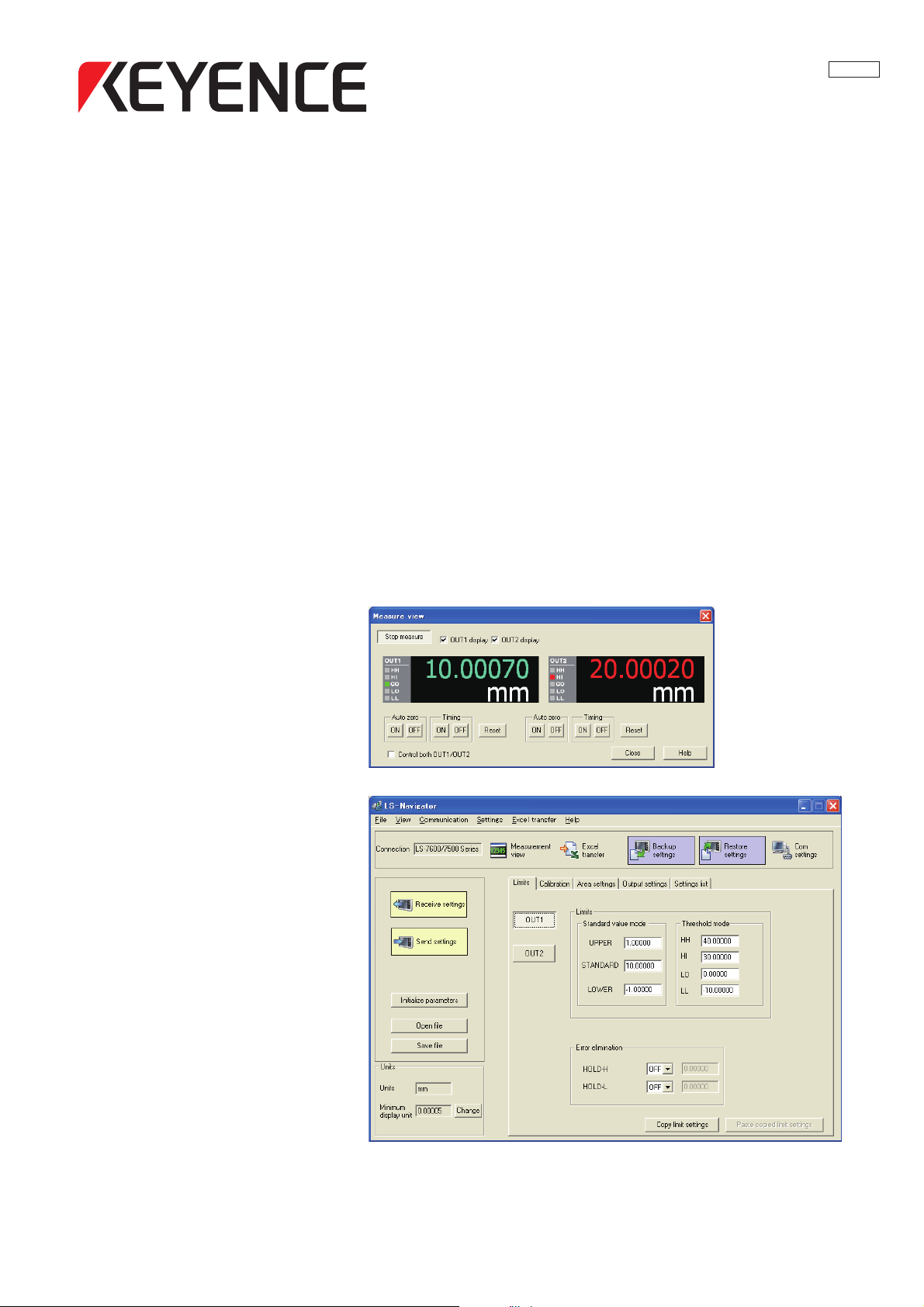
Measurement value monitoring and control function
The measurement values or judgment results that are measured on the controller can be monitored in real time on
the computer. The view can be selected from OUT1 display, OUT2 display, or simultaneous display of OUT1 and
OUT2. The value can be controlled by using auto-zero, timing, or the reset button.
1
Example of the measurement view menu
LS-Navigator-M-NO1-E
1-3
Page 12
1
1-1 LS-Navigator Overview
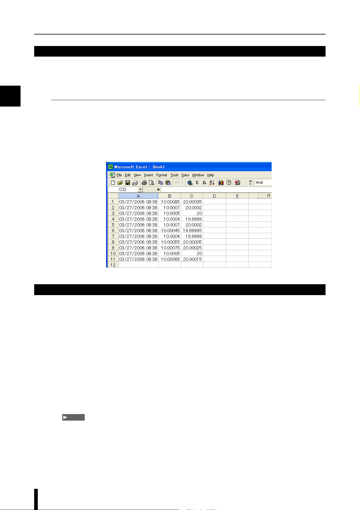
Function for transferring measurement values to an Excel sheet
The measured values that are received from the controller can be transferred to an Excel sheet with the
specifications from the specified logging method
Logging methods
1. Click logging : Transfers the measurement values when the button is clicked.
2. Timer logging : Transfers the measurement values at specified intervals.
3. External trigger logging: Transfers the measurement values when the controller communication setting is
[Printer Mode] and a trigger (timing input) is entered from the controller.
Example of transfer to an Excel sheet
Setting conditions
Operations that use LS-Navigator require certain setting conditions.
Set the following conditions before using the software.
1. Switch the controller to [Measurement] mode when communicating between the computer and the controller.
2. The connected model selected on the LS-Navigator (computer) must be the same as the controller model (LS-
7600/LS-7500/LS-7000 series).
3. The connected model selected on the LS-Navigator (computer) must be the same as the controller model (LS-
7600/LS-7500/LS-7000 series).
4. The settings for [Units] ([D-UNIT]) and [Minimum display unit] ([D-RES]) must be the same for the LS-
Navigator (computer) and the controller (LS-7600/LS-7500/LS-7000 series).
5. [PANEL] must be set for [P-SELECT] in the environment settings for the controller.
[NORMAL] must be set for [D-MODE].
Note
When [Ext trig logging] is selected as the method for transferring the measurement value to the Excel sheet, select
[PRINTER1] or [PRINTER2] for [D-MODE].
6. When [TERMINAL] is set for [P-SELECT] in the environmental settings for the controller, the selected
program number cannot be sent or read. Also, backup and restore functions cannot be executed for all of the
settings.
1-4
LS-Navigator-M-NO1-E
Page 13

1-2 System Environment
The following system requirements are necessary to use LS-Navigator.
CPU Pentium III 400 MHz or greater
Compatible OS
Memory capacity 64 MB or greater
Display VGA (800 x 600 pixels) or greater, 256 colors or greater
Hard drive space 10 MB or greater
Interface RS-232C (serial port) interface built-in
Excel Excel 2010/2007/2003/2002/2000
*1 Home Premium, Professional, and Ultimate editions each are supported.
*2 Ultimate, Business, Home Premium, and Home Basic editions each are supported. For Windows Vista, Ver.
1.2 or above are supported.
*3 Professional and Home Edition editions each are supported.
Windows 7
Windows Vista
Windows XP
Windows 2000 Professional
*1
*2
*3
1
LS-Navigator-M-NO1-E
1-5
Page 14

1
MEMO
1-6
LS-Navigator-M-NO1-E
Page 15

2
Getting Started
This chapter describes how to connect the computer and the controller,
and how to install or uninstall LS-Navigator.
2-1 Connecting the Controller and the Computer ..... 2-2
2-2 Installing ............................................................. 2-3
2-3 Uninstalling......................................................... 2-6
LS-Navigator-M-NO2-E
2-1
Page 16
2
2-1
This section describes how to connect the controller and the computer by using RS-232C.
Note
This operation varies depending on the location and direction of the RS-232C port on the computer. Refer to the manual
that comes with the computer when connecting the RS-232C cord.
Connecting the Controller and the Computer
Connecting
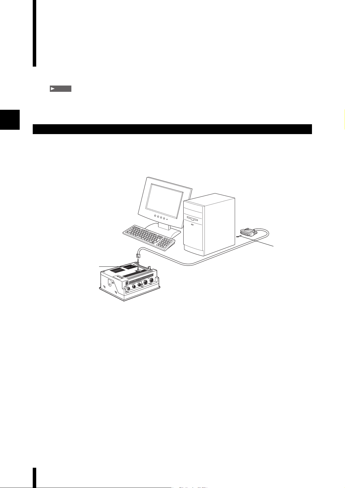
Connect the controller (LS-7600/7500/7000) and the computer by using RS-232C.
Use the cord OP-35382 (D-sub 9-pin) or OP-25253 (D-sub 25-pin) for connection.
Connection diagram
Computer
2
RS-232C cord
1
Controller
• LS-7600 series
• LS-7500 series
• LS-7000 series
Connect to the RS-232C connector for the
1
controller by using the cord OP-35382 (D-
sub 9-pin) or OP-25253 (D-sub 25-pin).
Connect to the RS-232C port for the
2
computer by using the cord OP-35382 (D-
sub 9-pin) or OP-25253 (D-sub 25-pin).
This procedure describes and example when
using OP-25253 (D-sub 25-pin).
OP-35382 (D-sub 9-pin)
or
OP-25253(D-sub 25-pin)
2-2
LS-Navigator-M-NO2-E
Page 17
2-2 Installing
This section describes the procedures for installing LS-Navigator to a computer.
Example of installation on Windows XP
This procedure describes how to install the software on Windows XP.
• Close all active applications before starting the installation.
• When installing on Windows 7, Windows Vista, Windows XP Professional Edition or Windows 2000
Professional, log in with a user name that has Administrator rights.
Insert the CD that contains this software
1
into the CD-ROM drive of the computer.
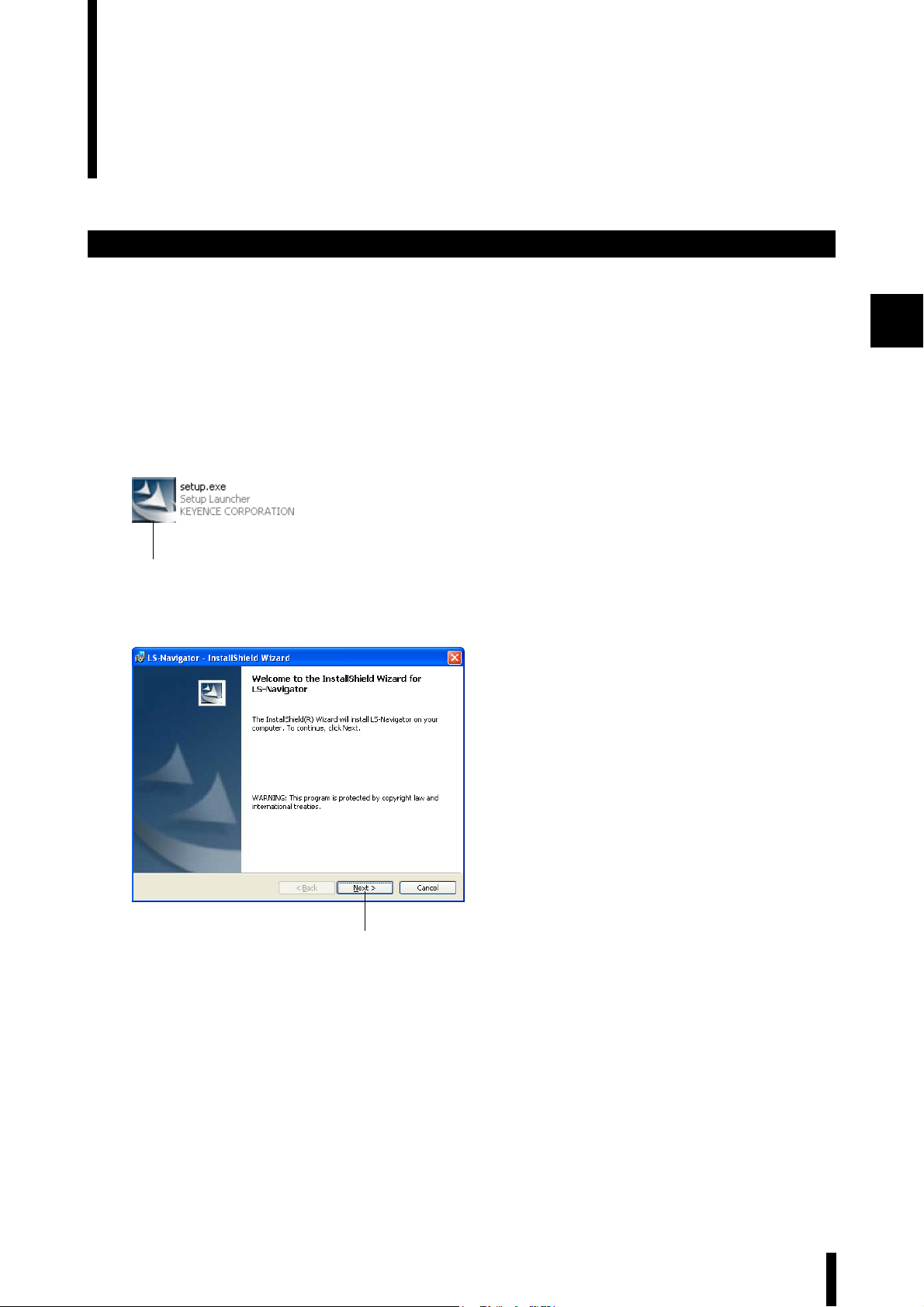
Double click on [setup.exe] in the [LS-
2
Navigator Installer] folder.
The installation software starts up and the
“Welcome” window for the InstallShield Wizard
2
appears.
2
Click on the [Next] button.
3
The [Customer Information] dialog appears.
3
LS-Navigator-M-NO2-E
2-3
Page 18
2
2-2 Installing
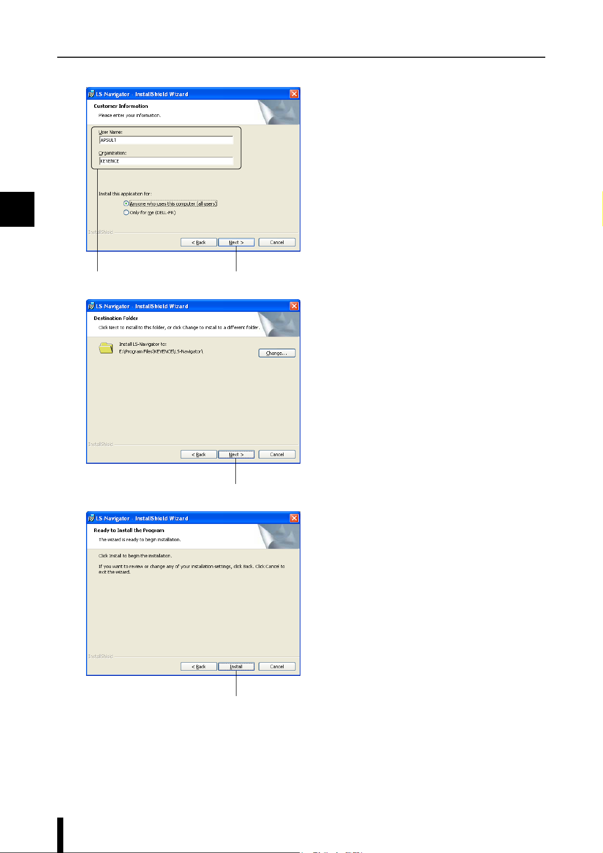
Enter the information into [User Name] and
4
[Company Name], and then click on the
[Next] button.
The [Destination Folder] dialog appears.
•
The default setting installs the software to "C:\Program
Files\KEYENCE\LS-Navigator".
• To install the software to a different folder, click
on the [Change] button and select the folder in the
[Change Current Destination Folder] dialog.
44
Click on the [Next] button.
5
A window appears with the message that the
program is ready to be installed.
5
Click on the [Install] button.
6
6
2-4
LS-Navigator-M-NO2-E
Page 19
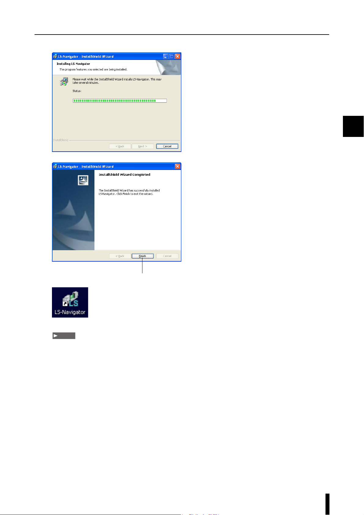
The program is installed.
7
When installation finishes, the
8
[InstallShield Wizard Completed] window
appears. Click on the [Finish] button to
complete the process.
An [LS-Navigator] shortcut appears on the
Desktop, and [LS-Navigator] appears under
[KEYENCE Applications] in the Windows
[Start] menu.
2-2 Installing
2
8
Note
The help file for this software was created in PDF file format. The viewing software Adobe Reader from Adobe Systems
Incorporated must be installed onto your computer to use the help file. We recommend using version 7.0 or greater. You
can download the latest version of Adobe Reader for free from the Adobe Systems Incorporated web site: http://
www.adobe.com
LS-Navigator-M-NO2-E
2-5
Page 20
2
2-3 Uninstalling
This section describes the procedures for uninstalling LS-Navigator from a computer.
Example of uninstallation on Windows XP
This procedure describes how to uninstall the software on Windows XP.
• Close all active applications before starting the uninstall process.
• When uninstalling on Windows 7, Windows Vista, Windows XP Professional Edition or Windows 2000
Professional, log in with a user name that has Administrator rights.
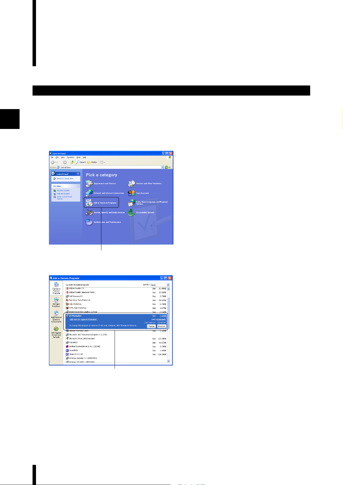
Double click on [Add or Remove Programs]
1
in the Control Panel.
The [Add or Remove Programs] window appears.
1
Select [LS-Navigator] and click on
2
[Remove].
The [Add or Remove Programs] dialog appears.
Follow the on-screen directions to
2
If the program is not uninstalled after performing steps 1 to 3, continue on and perform the following steps 4 to 6.
Step 4: Insert the CD that contains the software into the drive and double click on [setup.exe] in the [LS-
Navigator Installer] folder. A window appears to confirm uninstallation for LS-Navigator.
3
uninstall the software.
2-6
Step 5: Click on the [Remove] button.
A window appears to confirm completion of the uninstallation.
Step 6: Click on the [Finish] button to complete the process.
LS-Navigator-M-NO2-E
Page 21

3
Names and Functions of
Parts of the Window
This chapter describes the names and functionsof each part of the LS-Navigator window.
3-1 Main Window...................................................... 3-2
3-2 Menu Bar............................................................ 3-3
3-3 Tool Bar .............................................................. 3-5
LS-Navigator-M-NO3-E
3-1
Page 22

3-1 Main Window
This section describes the main window.
Names and functions of parts of the main window
3
Communication and file
operation area
Initializes parameters, opens or
saves setting files, and receives
or sends controller parameters.
Menu bar
Displays the operational
menus for LS-Navigator.
Too l bar
Displays the connected
model and buttons for
frequently used menus.
Program setting area
Set the parameters for [Limits],
[Calibration], [Area settin
[Outpu
t settings], and then check
the settings in [Settings list].
For more details, see "Setting
the Program" (Page 5-18).
gs], and
3-2
Unit setting area
Set and change the units and minimum
display unit for the selected program.
For more details, see “Setting and
Changing Units” (Page 5-5).
Copy and paste
Copies and pastes the parameters for each
of the measurement condition settings.
LS-Navigator-M-NO3-E
Page 23

3-2 Menu Bar
This section describes the command names and the functions for each menu in the menu bar.
Command names and functions for each menu
File menu
Command name Function Reference page
Open file Reads a saved setting file for the
controller.
Save file Saves a setting file for the
controller.
Exit Exits LS-Navigator. Page 4-5
View menu
Page 5-3
Page 5-4
3
Communication menu
Command name Function Reference page
Measure view Displays the measurement value
for the controller.
Command name Function Reference page
Send settingsSends parameters set on the
computer to the controller.
Receive settings Receives setting parameters for
the controller on the computer.
Backup settingsSaves all of the program setting
parameters for the controller on
the computer as a backup file.
Restore settings Restores all of the program setting
parameters for the controller from
a backup file saved on the
computer.
Page 5-6
Page 5-7
Page 5-8
Page 5-10
Page 5-11
LS-Navigator-M-NO3-E
3-3
Page 24

3
3-2 Menu Bar
Settings menu
Command name Function Reference page
Change connection Change the model of the
Communication
settings
Change program
No.
verification
Option Sets whether to display the
connected controller (LS-7600/LS-
7500 series or LS-7000 series).
Reference
•Changing the connected model
sets the following setting data to
the default values: Limit settings,
Calibration settings, Area
settings, and Output settings.
•Changing the connected model
also changes the extension for
the backup file.
Sets the communication
conditions for the RS-232C
connection that connects the
computer
Switches and verifies the program
No. for the connected controller.
“Welcome” message at startup.
and the controller.
Page 5-2
Page 5-12
Page 5-18
-
Excel transfer menu
Help
Command name Function Reference page
Start logging Performs settings for transferring
measurement values to an Excel
sheet or settings for the logging
method.
Command name Function Reference page
View help Displays this manual as a PDF file. -
AboutDisplays the version of LS-
Navigator.
Page 5-19
-
3-4
LS-Navigator-M-NO3-E
Page 25

3-3 Tool Bar
This section describes the names and functions of each tool in the tool bar.
Names and functions of the tools
Tool bar
Connection
Tool name Function Reference page
Connection Displays the model of the currently
connected controller.
3
Page 5-2
Measurement view
Excel transfer
Backup settings
Tool name Function Reference page
Measurement view Displays the measurement values
acquired from the controller in the
[Measure view] window.
Tool name Function Reference page
Excel transfer Records the measurement values
Tool name Function Reference page
Backup
settings
acquired from the controller in an
Excel sheet.
Saves all of the settings for the
controller on the computer as a
backup file.
Page 5-6
Page 5-19
Page 5-10
LS-Navigator-M-NO3-E
3-5
Page 26

3
3-3 Tool Bar
Restore settings
Communication settings
Tool name Function Reference page
Restore settings Restores all of the settings for the
Tool name Function Reference page
Communication
settings
controller from a backup file saved
on the computer.
Sets the communication
conditions for the RS-232C
connection that connects the
computer and the controller.
Page 5-11
Page 5-12
3-6
LS-Navigator-M-NO3-E
Page 27

4
Operation Flow from Startup
to Shutdown
This chapter describes the basic flow of operations for the LS-Navigator from startup to shutdown.
4-1 Basic Flow of Operations.................................... 4-2
4-2 Basic Procedures for Operation ......................... 4-3
LS-Navigator-M-NO4-E
4-1
Page 28

4
4-1 Basic Flow of Operations
The following chart shows the flow of operations for the LS-Navigator from startup to shutdown.
Operation flow from startup to shutdown
Connect the controller and the computer by using RS-232C.
Page 2-2
Start up the controller and set it to [Measurement] mode.
Next, start up the computer.
Page 1-4
Start up LS-Navigator.
Page 4-3
select the model for the controller that is connected to the computer and
When [Read controller
settings] is selected
Set the same RS-232C communication
conditions and settings as used on the
controller.
The settings are read from the
In the main window, the software can be used to display measurement
In the [Select the settings to display at startup] dialog,
choose the setting contents to read.
Page 5-12
controller.
Page 4-4
values, set programs on the controller, backup settings,
and send or receive setting files. Page 4-5
Page 4-4
When [Read from file] or [Start with
defaults] are selected, the software
reads the default values or the data
saved to a file.
Page 4-4
Set the same RS-232C communication
conditions and settings as used on the
controller.
Page 5-12
4-2
Exit LS-Navigator.
Page 4-5
LS-Navigator-M-NO4-E
Page 29

4-2 Basic Procedures for Operation
This chapter describes the basic procedures for operation for the LS-Navigator from startup to shutdown.
Basic procedures from startup to shutdown
Run LS-Navigator by double clicking on the
1
[LS-Navigator] shortcut icon on the
Desktop or by clicking on [All Programs] in
the Start menu and selecting [LSNavigator] from [KEYENCE Application].
The “Welcome” message appears. This message
indicates that there are restrictions on the
parameters that can be set on the software.
Note
Uncheck the box next to [Show this message on next
startup] to skip this message on the next startup.
For the parameters that can be set, see Page 1-2.
Click on the [Close] button.
2
The [Select the settings to display at startup]
window appears.
4
LS-Navigator-M-NO4-E
2
4-3
Page 30

4-2 Basic Procedures for Operation
Select the model of the controller
3
connected to the computer from the
following options.
LS-7000 Series, LS-7600/LS-7500 Series
Note
The model of the controller connected to the
computer must be the same as the model selected in
this window on LS-Navigator.
Select the method for reading the setting
4
contents from the following options.
Read controller settings, Read from file, Start
with defaults
4
4
3
■ When [Read controller settings] is
selected
After the [Communicating...] message appears,
the [Parameter update results] message is
displayed. Click on the [OK] button to display the
main window.
Note
When selecting [Read controller settings], click on
the [Communication Settings] button and change the
values in the [Communication settings] dialog so that
the values for the RS-232C communication
conditions on the software are the same as on the
controller. Click on the [Comm check] button to check
whether the RS-232C communication conditions are
the same on the controller and the computer.
For more details, see “Setting RS-232C
Communicatio
manual.
■ When [Read from file] is selected
The [Open] dialog appears. Select the file to load
and click on the [Open] button to display the
main window.
For more details, see “Reading setting files”
(Page 5-3).
n Conditions” (Page 5-12) in this
4-4
■ When [Start with defaults] is selected
The [Select the settings to display at startup]
window disappears and the main window is
displayed.
LS-Navigator-M-NO4-E
Page 31

Main window
4-2 Basic Procedures for Operation
Perform necessary actions such as
5
displaying the measurement values,
sending or receiving setting files, setting
the measurement conditions for the
program, or backing up and saving the
settings.
For more details, see “Chapter 5: Operating and
Setting Functions” (Page 5-1).
4
Select [Exit] from the [File] menu to exit LS-
6
Navigator.
6
LS-Navigator-M-NO4-E
4-5
Page 32

4
MEMO
4-6
LS-Navigator-M-NO4-E
Page 33

5
Operating and Setting
Functions
This chapter describes how to operate the functions and perform settings in the LS-Navigator.
5-1 Setting and Changing the Connection................ 5-2
5-2 Reading and Saving Setting Files ......................5-3
5-3 Setting and Changing Units................................ 5-5
5-4 Viewing the Measurement Value ........................ 5-6
5-5 Sending, Receiving, and Initializing Settings...... 5-7
5-6 Backing up or Restoring All Settings ................ 5-10
5-7 Setting RS-232C Communication Conditions...5-12
5-8 Verifying and Changing the Program No. ......... 5-18
5-9 Transferring the Measurement Values to Excel 5-19
5-10 Setting the Measurement Conditions for the
Program............................................................ 5-22
LS-Navigator-M-NO5-E
5-1
Page 34

5
5-1
This section describes how to set and change the controller connected to the computer.
Setting and changing the connected controller
Setting and Changing the Connection
Select [Change connection] from the
1
1
[Settings] menu.
A message appears to confirm changing the
model.
Click on the [OK] button.
2
The [Model selection] dialog appears.
2
Select the model to set.
3
For this example, select LS-7600/LS-7500 series.
43
Click on the [OK] button.
4
The connected model is changed and
[Connection] in the tool bar changes to [LS-7600/
LS-7500 Series].
Example of the [Connection] display
5-2
LS-Navigator-M-NO5-E
Page 35

5-2 Reading and Saving Setting Files
This section describes how to read setting files from the computer and save files to the computer.
Reading setting files
Select [Open file] from the [File] menu.
1
1
1
Or click on the [Open file] button in the
communication and file operation area.
The [Open] dialog appears.
5
Select a setting file (extension: *.lsc) and
2
click on the [Open] button.
The setting file is read.
2
LS-Navigator-M-NO5-E
5-3
Page 36

5-2 Reading and Saving Setting Files
Saving setting files
Select [Save file] from the [File] menu.
1
Or click on the [Save file] button in the
1
1
parameter settings area.
The [Save As] dialog appears.
Enter a file name and click on the [Save]
2
button.
The setting file is saved.
5
2
5-4
LS-Navigator-M-NO5-E
Page 37

5-3 Setting and Changing Units
Set the same values for [Units] and [Minimum display unit] on LS-Navigator as for the controller
program.
Click on the [Change] button in the unit
1
setting area.
The [Unit setting] dialog appears.
1
Use the pull-down menu to set the values
2
for [Units] and [Minimum display unit] the
same as in the controller.
Reference
Yo u can check the settings for [Units] and [Minimum
display unit] in the controller by looking at [Option]
settings in [Setting] mode.
See the “Minimum Display Unit” section in the
“User’s Manual” for each controller.
5
LS-Navigator-M-NO5-E
32
Click on the [OK] button to complete the
3
settings.
The set information appears in the unit setting
area.
5-5
Page 38

5
5-4 Viewing the Measurement Value
The measurement values that are measured on the controller can be monitored in real time on the computer.
Note
The communication settings for the computer and the controller must be set correctly for this function to operate.
The settings can be verified by clicking on the [Comm check] button in the [Communication settings] menu. This menu
can be displayed by clicking on the [Com settings] button on the tool bar.
See “Setting RS-232C Communication Conditions” (Page 5-12) in this manual.
Select [Measure view] from the [View]
1
1
1
menu.
Or click on the [Measurement view] icon on
the tool bar.
The [Measure view] window appears.
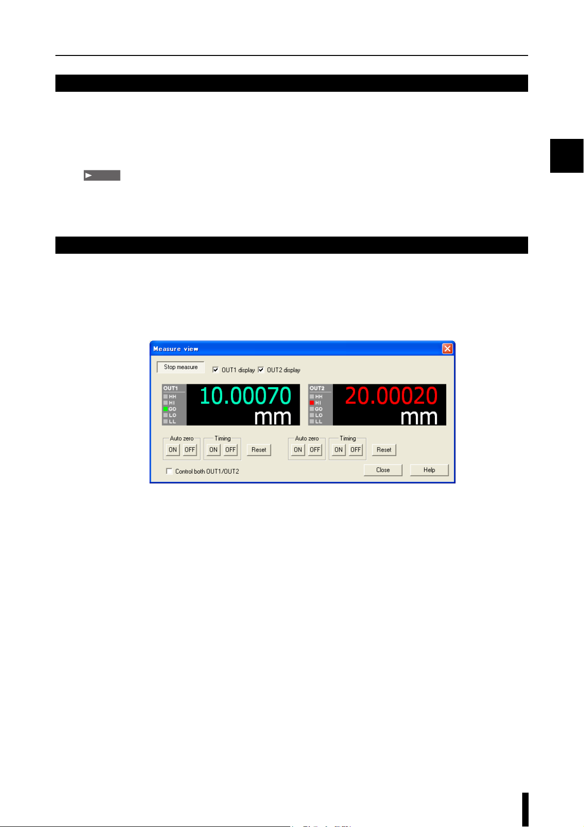
Click on the [Start measure] button in the
2
[Measure view] window.
The measurement values from the controller
appear in the [Measure view] window.
2
1 2
4 5
1. Switches between starting and stopping acquisition of the measurement value.
2. When a check mark is placed in the box, the measurement value for [OUT1] on the controller is displayed.
3. When a check mark is placed in the box, the measurement value for [OUT2] on the controller is displayed.
4. Displays the level of the limit judgment.
5. Turns on or off the [Auto zero] function.
See the “Automatic Zero Function” section in the “User’s Manual” for each controller.
6. Turn this option on to control both OUT1 and OUT2 simultaneously.
7. Turns on or off [Timing].
Use with the measurement mode function to control the measurement.
8. Resets the measurement values.
6
3
8
7
5
7
34
8
5-6
LS-Navigator-M-NO5-E
Page 39

5-5
This section describes how to send and receive setting files between the computer and
controller, as well as how to initialize them.
Sending settings
Sending, Receiving, and Initializing Settings
Select [Send settings] from the
1
1
[Communication] menu.
Or click on the [Send settings] button in
the communication and file operation area.
The [Send] dialog appears.
Select either [Current program No.] or
2
[Specify the program No.] and select a
program No. from the pull down menu.
Click on the [OK] button, and the
3
[Communicating] dialog appears.
32
When the communication is complete, the
[Parameter update results] window appears and
the sent parameters are displayed.
5
LS-Navigator-M-NO5-E
5-7
Page 40

5-5 Sending, Receiving, and Initializing Settings
4
Click on the [Close] button to complete the
4
process.
5
Receiving settings
Select [Receive settings] from the
1
[Communication] menu.
1
Or click on the [Receive settings] button in
the communication and file operation area.
The [Receive] dialog appears.
Select either [Current program No.] or
2
[Specify the program No.] and select a
program No. from the pull down menu.
Click on the [OK] button, and the
3
[Communicating...] dialog appears.
5-8
32
LS-Navigator-M-NO5-E
Page 41

5-5 Sending, Receiving, and Initializing Settings
When the communication is complete, the
[Parameter update results] window appears and
the received parameters are displayed.
Click on the [Close] button to complete the
4
process.
4
Initializing setting parameters
This section describes how to initialize setting parameters read by LS-Navigator.
1
Click on the [Initialize parameters] button
1
in the parameter settings area.
A message appears to confirm that all of the
parameters will be initialized.
5
LS-Navigator-M-NO5-E
Click on the [OK] button to initialize all of
2
the setting parameters on the LSNavigator
Reference
The setting parameters on the controller are not
initialized. Send the settings to initialize the setting
parameters on the controller.
2
.
5-9
Page 42

5-6
This section describes how to back up or restore all 16 programs and environment setting
information for the controller.
Backing up all settings for the controller
Backing up or Restoring All Settings
Select [Backup settings] from the
1
[Communication] menu.
Or click on the [Backup settings] icon on
the tool bar.
1
1
The [Save As] dialog appears.
5
Enter a file name and click on the [Save]
2
button.
The [Communicating...] dialog appears and the
software begins backing up the setting parameters
for the controller. After the backup finishes, the
backup completion message appears.
The backup files use the following extensions.
• For LS-7600/7500 : .lsbh
• For LS-7000 : .lsbs
2
Click on the [OK] button to complete the
3
process.
5-10
3
LS-Navigator-M-NO5-E
Page 43

Restoring all settings for the controller
1
1
5-6 Backing up or Restoring All Settings
Select [Restore settings] from the
1
[Communication] menu.
Or click on the [Restore settings] icon on
the tool bar.
The [Open] dialog appears.
Enter the name of the backup file that you
2
want to restore and click the [Open] button.
The [Communicating...] dialog appears and the
software begins backing up the settings for the
controller. After the restoration finishes, the
restoration completion message appears.
5
2
Click on the [OK] button to complete the
3
process.
3
LS-Navigator-M-NO5-E
5-11
Page 44

5
5-7
This section describes how to set the same RS-232C communication conditions on LS-
Navigator as used on the connected controller.
Setting RS-232C Communication Conditions
The software can check the following RS-
1
232C communication conditions for the
controller environment settings.
• Baud rate ([BAUDRATE])
• Stop bit ([STOPBIT])
• Data length ([D-LENGTH])
• Data mode ([D-MODE])
• Data send mode ([D-SEND])
Use the following procedure to check the RS232C communication conditions.
For the LS-7600/7500 series
Press and hold the [ESCAPE] button while in
[Setting] mode for at least three seconds, and then
check the settings in the [Environment settings]
menu that appears.
For more details, see “Environment Settings” in
the “User’s Manual” for the LS-7600/7500 series.
For the LS-7000 series
Press the [FUNC] key once during [Program]
view, and then check the settings in the [RS232C] view that appears.
For more details, see “RS-232C” in the “User’s
Manual” for the LS-7000 series.
Select [Communication settings] from the
2
[Settings] menu.
2
2
Or click on the [Com settings] icon on the
tool bar.
The [Communication settings] dialog appears.
5-12
LS-Navigator-M-NO5-E
Page 45

5-7 Setting RS-232C Communication Conditions
Click on the [Setting wizard] button in the
3
[Communication settings] dialog.
[Setting Wizard] is different for the LS-7600/
7500 series and the LS-7000 series starting from
step 4.
3
For the LS-7600/7500 series
For the LS-7000 series
Click on the [Next] button.
4
A confirmation message on the [Setting Wizard]
asks whether the RS-232C cable is connected to
the communication port.
4
5
LS-Navigator-M-NO5-E
4
5-13
Page 46

5-7 Setting RS-232C Communication Conditions
5
For both the LS-7600/LS-7500 series and
the LS-7000 series
5
For the LS-7600/7500 series
Select the port for RS-232C
5
communication.
Select between COM1 to COM8 from the pulldown menu.
Select the serial port number on the computer for
the connected controller.
Click on the [Next] button.
6
A message appears on the [Setting Wizard],
instructing the user to switch the controller to the
environment settings display. Use the following
procedure to display the environment settings for
the controller.
For the LS-7000 series
■ For the LS-7600/7500 series
Press and hold the [ESCAPE] button for at least
three seconds while in [Setting] menu of the
controller. The controller switches to the
environment settings display.
■ For the LS-7000 series
Press the [PROG] key while pressing the [FUNC]
6
key in the sub-display menu for the controller.
The display switches to [PROG]. Press the
[FUNC] key to switch the display to [RS-232C].
5-14
6
LS-Navigator-M-NO5-E
Page 47

For the LS-7600/7500 series
5-7 Setting RS-232C Communication Conditions
Click on the [Next] button.
7
A message appears on the [Setting Wizard],
instructing the user to set the same values as
shown for the communication settings on the
controller.
The communication settings for the LS-7600/7500
series and the LS-7000 series are different in the
following manner.
(1)
(2)
(3)
(4)
6
(1) Set the same value for [Baud rate] as displayed on the controller.
Select among 1200, 2400, 4800, 9600, 19200, 36400, 57600, or 115200 from the pull-down menu.
(2) Set the same value for [Parity] as displayed on the controller.
Select among NONE, ODD, or EVEN from the pull-down menu.
(3) Set the same value for [Stop bit] as displayed on the controller.
Select between 1 and 2 from the pull-down menu.
(4) Set the same value for [Data length] as displayed on the controller.
Select between 7 and 8 from the pull-down menu.
5
LS-Navigator-M-NO5-E
5-15
Page 48

5
5-7 Setting RS-232C Communication Conditions
For the LS-7000 series
The following steps describe the different methods for checking each of the communication conditions on the
controller
(1) Baud rate
Press the [ENT] key on the controller to switch the display
to [BAUDRATE].
Set the same value for [Baud rate] as displayed on the
controller.
Select among 1200, 2400, 4800, 9600, 19200, 36400,
57600, or 115200 from the pull-down menu.
(2) Parity
Press the [FUNC] key on the controller to switch the display
to [PARITY].
Set the same value for [Parity] as displayed on the
controller.
Select among NONE, ODD, or EVEN from the pull-down
menu.
(3) Stop bit
(4) Data length
Press the [FUNC] key on the controller to switch the display
to [STOPBIT].
Set the same value for [Stop bit] as displayed on the
controller.
Select between 1 and 2 from the pull-down menu.
Press the [FUNC] key on the controller to switch the display
to [D-LENGTH].
Set the same value for [Data length] as displayed on the
controller.
Select between 7 and 8 from the pull-down menu.
5-16
LS-Navigator-M-NO5-E
Page 49

5-7 Setting RS-232C Communication Conditions
Check that the [D-MODE] setting on the
8
controller is [NORMAL], and then click on
the [Next] button on the [Setting Wizard].
For the LS-7600 series
For the LS-7000 series
After checking all of the messages, click on
9
the [End] button.
The display returns to the [Communication
settings] window. Use the following procedure to
check the [D-MODE] setting for the controller.
■ For the LS-7600/7500 series
Press and hold the [ESC] button for at least three
seconds while in [Setting] menu of the controller.
Check the [D-MODE] setting in the
[Environment Setting] menu that appears.
■ For the LS-7000 series
Press the [FUNC] key four times in the [RS-232C
display] menu for the controller. Press the [▲]
9
and [▼] keys to select [D-MODE] and check the
setting.
5
10
9
Switch the controller to [Measurement]
10
mode and click on the [Comm check]
button in the [Communication settings]
dialog for LS-Navigator.
The “Connection status OK” message appears
and settings are completed.
LS-Navigator-M-NO5-E
5-17
Page 50

5
5-8
This section describes how to change and verify the program No. that is read by the computer.
Verifying and Changing the Program No.
Select [Change program No. verification]
1
from the [Settings] menu.
The [Change program No. verification] dialog
1
appears.
Note
For the LS-7600/7500 series, the displayed value for
program No. is “00 to 15”.
For the LS-7000 series, the displayed value for
program No. is “0-9, A-F”.
To verify the program No. that is currently being read,
click on the [Check] button.
To c h ange the program No., select the program No.
to read from the pull-down menu
and click on the [Run] button.
Note
When switching the program number, [PANEL] must be set for [P-SELECT] in the environment settings for the controller.
For more details, see the “Details of Environment Settings” section in the “User’s Manual” for each controller.
5-18
LS-Navigator-M-NO5-E
Page 51

5-9
This section describes how to transfer measurement values that are read from the controller to
an Excel sheet.
Transferring the Measurement Values to Excel
Select [Start logging] from the [Excel
1
1
1
transfer] menu.
Or click on the [Excel transfer] icon on the
tool bar.
The [Logging] dialog appears.
Set the appropriate values for the transfer
2
items, the transferring sheet name, the
logging method, and any other required
parameters.
Select the items to transfer to the Excel sheet.
Items that can be transferred: Date (mdyhms),
OUT1, OUT2
Set the name of the Excel sheet to
transfer information to, and set the cell to
start writing.
Set the logging method and logging
cycle (seconds).
From the pull-down menu, select
one of the following three types of
logging methods: [Click logging],
[Timer logging], and [Ext trig
logging].
When [Timer logging] is selected,
set [Logging cycle]. The cycle can
be set in 1 second intervals from 1
to 600 seconds.
When [Ext trig logging] is selected,
select [PRINTER1] or [PRINTER2]
for [D-MODE].
3
5
LS-Navigator-M-NO5-E
5-19
Page 52

5-9 Transferring the Measurement Values to Excel
For click logging
For timer logging
Click on the [Start logging] button.
3
The dialog for the selected logging method
appears.
Data is transferred to the Excel sheet every time
the [Measurement value output] button is clicked.
5
After clicking on the [Start output] button, data is
transferred to the Excel sheet at the intervals set
in [Logging cycle].
The [Start output] button changes to the
[Outputting...] button.
5-20
LS-Navigator-M-NO5-E
Page 53

For trigger logging
PRINTER1
Tr ansfers only the
measurement values.
PRINTER2
Tr ansfers the measurement
values and the limit
judgment results.
5-9 Transferring the Measurement Values to Excel
After clicking on the [Start receiving data]
button, data is transferred to the Excel sheet every
time there is a timing input from the input
terminal on the controller.
The data outputs as seen to the left with [D-
MODE] settings.The [Start receiving data] button
changes to the [Standby...] button.
Note
・ When performing trigger logging, set the same settings
for LS-Navigator and [D-MODE] in the controller, and
then select [PRINTER1] or [PRINTER2].
・ [D-SEND] on the controller can be set to “S1: Output
All Measured Values” or “S2: Output NG Measured
Valued”.
・ To stop trigger logging and return the LS-Navigator to
normal operations, set [D-MODE] in the controller to
[NORMAL].
For more details, see the “Connecting to
Printers” section in the “Userís Manual” for
each controller.
5
Example of transfer to an Excel sheet
(for timer logging)
Click on the [Measurement value output],
4
[Start output], or [Start receiving data]
button in the dialog.
The measurement values are transferred to the
Excel sheet.
Note
Measurement values cannot be transferred if the
Excel file is being used for other applications.
To stop the timer logging, click on the
5
[Outputting...] button.
To stop external trigger logging, click on
the [Standby...] button.
Note
The output cycle for timer logging uses the internal
clock in the computer.
Cumulative errors in the internal clock may lead to
errors in the output cycle.
LS-Navigator-M-NO5-E
5-21
Page 54

5-10
This section describes how to set the measurement conditions for [Limits], [Calibration], [Area
settings], and [Output settings].
Setting the Measurement Conditions for the Program
Limits
Click on the [Limits] tab in the program
1
setting area.
The [Limits] window appears.
Set [Limits] for OUT1 and OUT2.
2
5
Set the standard value, as well as the
upper and lower limits for the deviation.
The measurement is judged as one of
three levels: HI, GO, or LO.
1
Select the output (OUT1
or OUT2).
Copies the limit settings from
OUT1 or OUT2 and pastes
them into OUT1 or OUT2.
Set the upper limits and lower limits with
absolute values. The measurement is judged
as one of five levels: HH, HI, GO, LO, or LL.
Reference
The range for each parameter depends on the
settings for [Units] and [Minimum display unit].
If dust or foreign objects become attached to
the measurement target, the displayed
measurement value may become extremely
inaccurate. If dust or foreign objects become
attached to the measurement target, the
displayed measurement value may become
extremely inaccurate
set on, measurement values that exceed the
upper limit for errors (HOLD-H) or fall below the
lower limit for errors (HOLD-L) are automatically
detected and eliminated. Select [ON] from the
pull-down menu and enter the upper limit or
lower limit for errors in the text box.
. When this para
meter is
5-22
Note
・ Use the controller to change settings in limit mode.
For more details, see the “Tolerance Settings” section in the “User’s Manual” for each controller.
・ Set the same values for [Units] and [Minimum display unit] in the settings for the controller and LS-Navigator. (Refer to
Page 5-5.)
LS-Navigator-M-NO5-E
Page 55

Calibration
5-10 Setting the Measurement Conditions for the Program
Click on the [Calibration] tab in the
1
program setting area.
The [Calibration] window appears.
Set [Logic calibration] for area 1 and area
2
2.
1
Enter the values for two points (target 1 and target
2) on the workpiece.
The values are displayed as follows:
Before calibration After calibration
FirstT1-A: Displayed
Second T2-A: Displayed
The value for calibration span is automatically
calculated after the above values are entered.
The calibration span is display
value.
value for target 1
before calibration
value for target 2
before calibration
T1-B: Displayed
value for target 1
after calibration
T2-B: Displayed
value for target 2
after calibration
ed as a ref
erence
5
Select the area (area 1 or
area 2).
Copies the calibration settings
from area 1 or area 2 and pastes
them into area 1 or area 2.
Note
When setting the calibration mode, enter values
that meet the following relationship:
T1-A < T2-A and T1-B < T2-B
Set the values so that the calibration span is
greater than 0.5 and smaller than 2.0.
Note
These settings are effective when [Calibration
Settings] for the controller is set to logic calibration
mode.
For more details, see the “Calibration Settings”
section in the “User’s Manual” for each controller.
LS-Navigator-M-NO5-E
5-23
Page 56

5
5-10 Setting the Measurement Conditions for the Program
Area settings
1
Click on the [Area settings] tab in the
1
program setting area.
The [Area settings] window appears.
Set which area of the target to measure.
2
Select the head (head 1 or head 2) to use
for measurement.
Select [ON] or [OFF] from the pull-down
menu. When the parameter is set to [ON],
set the total number of edges for
measurement. When the value has a
different number of edges, the
measurement value becomes invalid. This
prevents the output of measurement values
that are incorrect due to dust or oil on the
measurement head.
Parameter range: 2 to 127
Set two areas
(area 1 or area
2) on the
measurement
target.
Select the measurement method from the pull-down menu.
Measurement
method
DIA Set this method when measuring the outer diameter of a round bar or a transparent body. This method
T- E D G E Set this method when measuring the gap between rollers or when setting a position. T-EDGE measures the
E Set this
B-EDG
SEG Set this method when measuring the inner diameter of a disk or when measuring pitch.
Set the detection threshold value
when measuring a target that has high
transparency. Enter a value into the
text box.
Parameter range: 10 to 99%
Type of measurement
measures the target from the first falling edge (an edge where a bright portion becomes dark) to the last
rising edge (an edge where a dark portion becomes bright).
width of the first bright portion on the top of the target.
method when measuring the gap between rollers or when setting a position. B-EDGE measures the
width of the last bright portion on the top of the target.
This method measures the width between two specified edges: the start edge where measurement is
started and the end edge where measurement is finished.
Parameter range: 0, ±1 to ±127, E or P
Copies the calibration settings from area 1
or area 2 and pastes them into area 1 or
area 2.
5-24
LS-Navigator-M-NO5-E
Page 57

Output settings
5-10 Setting the Measurement Conditions for the Program
Click on the [Output settings] tab in the
1
program setting area.
The [Output settings] window appears.
Various processes are performed on the
2
values measured from area 1 and area 2,
and these results are output as OUT1 and
OUT2.
1
When the measurement mode is set to
[Self-timing hold] mode, set the selftiming time.
Parameter range: 1 to 9999 ms
This parameter can only be set during
[Self-timing hold] mode.
Calculations are performed using the
measurement values obtained from
measuring the two areas set in [Area
settings].
Select a value from the pull-down menu.
Valid settings:
0, +1, +1/2, -1, -1/2
Set the number of times for averaging from
the pull-down menu.
Set a larger value to average variations in
more
the measurement value and pro
stable result. Set a smaller value to
measure at high speeds.
Valid number of times for averaging:
1, 2, 4, 8, 16, 32, 64, 128, 256, 512, 1024,
2048, 4096
Select the method for output. Some methods
output the raw measurement value, while
others continuously measure a changing
value using a timing and output the maximum
or minimum values. Select the measurement
mode from the pull-down menu. The modes
as divided according to target and conditions
for measurement.
Valid measurement modes:
Normal, peak hold, bottom hold, peak-topeak hold, average hold, auto peak hold,
auto bottom hold, auto peak-to-peak hold,
sample hold 1, sample hold 2, self-timing
hold
For more details, see “Measuring Mode”
in the “User’s Manual” for each controller.
vide a
5
LS-Navigator-M-NO5-E
5-25
Page 58

5
5-10 Setting the Measurement Conditions for the Program
Copies the output settings from OUT1 or
OUT2 and pastes them into OUT1 or OUT2.
The entered value is added to or subtracted from the measurement
value.
When an offset value is set while using the auto zero function, the
offset appears on the display momentarily.
Valid range:
With the defaults, the range is -99.99999 to 99.99999 mm.
Reference
The offset value changes according to the units and the minimum
display unit setting.
For more details, see the sections “Display Unit” and “Minimum
Display Unit” in the “User’s Manual” for each controller.
Analog voltage is output for the measurement value.
For standard value mode: When the limit mode is
standard value, the standard value is represented by 0
V, and the output voltage is greater or smaller
depending on the deviation. Select one of the following
values from the pull-down menu.
Valid values:
1, 2, 5, 10, 20, 50, 100, 200, 500, 1000, 2000, 5000,
10000 µm/V
Threshold m
mode, set the measurement valu
output at +10 V and -10 V. These values determine the
scaling for the output.
Set the measurement values so that the absolute
value of their difference satisfies the conditions of the
following for mula.
Absolute value of { (Measurement value for +10 V) (Measurement value f
value for X changes depending on the minimum
The
display unit setting.
The following chart indicates the relationship between
X and the minimum display unit.
Minimum display unit (mm) X (mm)
0.00001, 0.00002, 0.00005 0.02
0.0001, 0.0002 0.2
0.001, 0.01, 0.1 2
0.01, 0.02, 0.05 20
0.1, 0.2 200
1 2000
For more details, see the “Analog Output Settings”
section in the “User’s Manual” for each controller.
Set the same values for [Units] and [Minimum display
unit] in the settings f
(Refer to Page 5-5.)
ode: When the limit mode is threshold
or -10V) } X
or the controller and LS-Navi
es that you want to
>_
gator.
5-26
Settings list
1
Click on the [Settings list] tab in the
1
program setting area.
A list of the set parameters appears in the
[Settings list] window.
Copy the settings to clipboard. Paste the
2
settings in another application, such as
Excel.
Reference
The parameters that have been changed from their
default values are displayed in blue.
2
LS-Navigator-M-NO5-E
Page 59

A
Appendix
This chapter describes error messages and shortcut keys.
1Error Message List .............................................A-2
2 Shortcut Key List ................................................A-4
3 Index...................................................................A-5
LS-Navigator-M-APP-E
A-1
Page 60

A
1 Error Message List
This section describes information about the displayed error messages that appear when an error occurs.
During operation
During data communication
Error message Cause Reference page
Failed to communicate. Communication is not possible when the
No response from the
controller.
controller is in setting mode.
Check whether the PC and controller have
the same communication settings.
Check whether the controller D-MODE
settings are correct.
Check the communication settings. The communication settings are not the
Check whether the cables are connected
correctly.
This port number is invalid.
Choose another port.
Process failed to finish correctly.
Restart the application.
Set the same values for units and
minimum display unit in the controller
settings and LS-Navigator settings.
Settings cannot be transferred if the units
are not the same.
the method for switching p
Set
settings in “PANEL”.
This backup file includes the dual head
mode in the setting contents. Check that
the connected model is LS-7600.
rogram
The controller is in setting mode. Page 1-4
The communication settings are not the
same on the PC and the controller.
The controller D-MODE settings are not
correct.
same on the PC and the controller.
The cables are not connected correctly. Page 2-2
An invalid port is selected. Page 5-12
When the data transfer process
finish.
The units for the controller and the LS-
Navigator are different.
The setting is not “PANEL”. Page 1-4
The backup file includes dual head mode
in the settings.
fails to
Page 5-12
Page 5-17
Page 5-12
Page 4-3
Page 5-5
Page 5-10
A-2
During Excel transfer
Error message Cause Reference page
Select at least one item to transfer. No items are selected for transfer. Page 5-19
Failed to output to Excel. Excel is being used. Page 5-19
Enter the sheet name to transfer items to. A sheet name for transferring items is not entered. Page 5-19
The following cannot be used in the name: Invalid characters are used in the sheet name. Page 5-19
The cell position is not set correctly. An invalid cell position is select
The loggi
Set the logging cycle between 1 and 600. The cycle is set in an invalid range. Page 5-19
No further information can be written. The system is attempting to write in an invalid range for
Enter up to 31 letters for the sheet name.
ng method is not selected correctly. The logging method is not selected correctly. Page 5-19
Excel.
On the logging menu, the [Start logging] button was
pressed when more than 31 letters were entered for the
sheet name. (Every character is treated the same as one
letter.)
ed. Page 5-19
Page 5-19
Page 5-19
LS-Navigator-M-APP-E
Page 61

1 Error Message List
Saving and reading settings
Error message Cause Reference page
The file name is too long. The file path name is too long. (The maximum path
name length is 255 characters.)
Failed to read the file.
Check that the correct file is set.
The file may be corrupted. Page 5-3
The file may be an incorrect type of data.Page 5-3
Page 5-4
Output settings
Error message Cause Reference page
Set the value for scaling within the range. Set the value for scaling within the range.
See the “Analog Output Settings” section in the “User’s
Manual” for each controller.
Page 5-26
Limit settings
Error message Cause Reference page
The upper limit must be larger than the lower limit. The lower limit is larger than the upper limit. Page 5-22
The value exceeds the standard value + upper limit. Set
the value between ( ) and ( ).
* The values displayed within the parentheses ( ) vary
depending on the units and the minimum display unit.
The HH setting must be larger than the HI setting.
The LO setting must be larger than the LL setting.
The HOLD-H value must be larger than the HOLD-L
value.
The value exceeds the setting range for standard value
per limit.
+ up
Se
e the “Units, Default Minimum Values, and Setting
Ranges” section in the “User’s Manual” for each
controller.
The HI setting is larger than the HH setting.
The LL setting is larger than the LO setting.
The HOLD-L value is larger than the HOLD-H value. Page 5-22
Page 5-22
-
Page 5-22
Page 5-22
A
Settings list
Error message Cause Reference page
Failed to copy to the clipboard. When the Windows OS fails to copy to the clipboard. Page 5-26
Reference: An error message may be displayed from the Windows OS.
When starting up
Error message Cause Reference page
Start with defaults.Appears when related files start up automatically and
the reading process fails.
Page 4-3
General application
Error message Cause Reference page
The HELP file cannot be opened. When the PDF HELP file cannot be opened because
the HELP file does not exist or Adobe Reader is not
installed.
-
LS-Navigator-M-APP-E
A-3
Page 62

A
2 Shortcut Key List
This section provides the shortcut keys that can be used on LS-Navigator.
Menu Submenu Shortcut keys Operation
File Open file Ctrl + O Opens a saved setting file.
Save file Ctrl + S Saves the settings as a file.
View Measure view F10 + V + V Switches between showing and hiding the
Communication Send settings F10 + C + SSends the information set on LS-Navigator to the
Receive settings F10 + C + L
Backup settings F10 + C + B Saves all of the settings on the connected controller to
Restore settings F10 + C + R Replaces all of the settings on the connected
Settings Change connection F10 + S + G Changes the model of the connected controller.
Communication settings F10 + S + C Performs the communication settings.
Change program No. verification F10 + S + P Switches and verifies the program No. for the
ption F
O
Excel Transfer Start logging F10 + E + S Tr ansfers the logging data to an Excel file.
Help View help F1 Runs help.
About F10 + H + A Displays the version of LS-Navigator.
10 + S + O Sets whether to display the “Welcome” message at
measurement view window.
controller.
Loads controller settings into LS-Navigator.
a file.
controller with the data from a backup file.
connected controller.
startup.
A-4
LS-Navigator-M-APP-E
Page 63

3 Index
A
Analog voltage . . . . . . . . . . . . . . . . . . . . . . . . 5-26
Area settings . . . . . . . . . . . . . . . . . . . . . . . . . 5-24
Auto zero function . . . . . . . . . . . . . . . . . . . . . . 5-6
B
Backup settings . . . . . . . . . . . . . . . . . . . 3-5, 5-10
Baud rate . . . . . . . . . . . . . . . . . . . . . . . 5-15, 5-16
B-EDGE . . . . . . . . . . . . . . . . . . . . . . . . . . . . . 5-24
C
Calibration . . . . . . . . . . . . . . . . . . . . . . . . . . . 5-23
Change connection . . . . . . . . . . . . . . . . . . . . . 5-2
Change program No. verification . . . . . . . . . . 5-18
Click logging . . . . . . . . . . . . . . . . . . . . 5-19, 5-20
Communication and file operation area . . . . . . 3-2
Communication menu . . . . . . . . . . . . . . . . . . . 3-3
Communication settings . . . . . . . . . . . . 3-6, 5-12
Connection . . . . . . . . . . . . . . . . . . . . . . . . . . . 3-5
Copy and paste . . . . . . . . . . . . . . . . . . . . . . . . 3-2
D
Data length . . . . . . . . . . . . . . . . . . . . . 5-15, 5-16
DIA . . . . . . . . . . . . . . . . . . . . . . . . . . . . . . . . . 5-24
H
Help . . . . . . . . . . . . . . . . . . . . . . . . . . . . . . . . . 3-4
I
Initialize parameters . . . . . . . . . . . . . . . . . . . . 5-9
Install . . . . . . . . . . . . . . . . . . . . . . . . . . . . . . . . 2-3
L
Limits . . . . . . . . . . . . . . . . . . . . . . . . . . . . . . . 5-22
Logging cycle . . . . . . . . . . . . . . . . . . . . . . . . 5-19
M
Measure view . . . . . . . . . . . . . . . . . . . . . .3-5, 5-6
Measurement mode . . . . . . . . . . . . . . . . . . . 5-25
Menu bar . . . . . . . . . . . . . . . . . . . . . . . . . .3-2, 3-3
Minimum display unit . . . . . . . . . . . . . . . . . . . 5-5
O
Offset . . . . . . . . . . . . . . . . . . . . . . . . . . . . . . 5-26
Open file . . . . . . . . . . . . . . . . . . . . . . . . . . . . . 5-3
Output settings . . . . . . . . . . . . . . . . . . . . . . . 5-25
P
A
E
Error message . . . . . . . . . . . . . . . . . . . . . . . . . A-2
Excel transfer . . . . . . . . . . . . . . . . . . . . . . . . . . 3-5
Excel Transfer menu . . . . . . . . . . . . . . . . . . . . 3-4
External trigger logging . . . . . . . . . . . . . . . . . 5-19
F
File menu . . . . . . . . . . . . . . . . . . . . . . . . . . . . . 3-3
LS-Navigator-M-APP-E
Parameter settings area . . . . . . . . . . . . . . . . . 5-4
Parity . . . . . . . . . . . . . . . . . . . . . . . . . . .5-15, 5-16
Port . . . . . . . . . . . . . . . . . . . . . . . . . . . . . . . . 5-14
Program setting area . . . . . . . . . . . . . . . . . . . 3-2
R
Receive settings . . . . . . . . . . . . . . . . . . . . . . . 5-8
Restore settings . . . . . . . . . . . . . . . . . . .3-6, 5-11
RS-232C communication conditions . . . . . . . 5-12
A-5
Page 64

A
3 Index
S
Save file . . . . . . . . . . . . . . . . . . . . . . . . . . . . . . 5-4
SEG . . . . . . . . . . . . . . . . . . . . . . . . . . . . . . . . 5-24
Send settings . . . . . . . . . . . . . . . . . . . . . . . . . . 5-7
Setting wizard . . . . . . . . . . . . . . . . . . . . . . . . 5-13
Settings list . . . . . . . . . . . . . . . . . . . . . . . . . . 5-26
Settings menu . . . . . . . . . . . . . . . . . . . . . . . . . 3-4
Shortcut key . . . . . . . . . . . . . . . . . . . . . . . . . . . A-4
Standard value mode . . . . . . . . . . . . . . . . . . 5-26
Start logging . . . . . . . . . . . . . . . . . . . . . . . . . 5-19
Start measure . . . . . . . . . . . . . . . . . . . . . . . . . 5-6
Stop bit . . . . . . . . . . . . . . . . . . . . . . . . 5-15, 5-16
T
T-EDGE . . . . . . . . . . . . . . . . . . . . . . . . . . . . . 5-24
Threshold mode . . . . . . . . . . . . . . . . . . . . . . . 5-26
Timer logging . . . . . . . . . . . . . . . . . . . . 5-19, 5-20
Timing . . . . . . . . . . . . . . . . . . . . . . . . . . . . . . . 5-6
Tool bar . . . . . . . . . . . . . . . . . . . . . . . . . . 3-2, 3-5
Transfer to the Excel sheet . . . . . . . . . . . . . . 5-19
Trigger logging . . . . . . . . . . . . . . . . . . . . . . . . 5-21
U
Uninstall . . . . . . . . . . . . . . . . . . . . . . . . . . . . . . 2-6
Unit setting area . . . . . . . . . . . . . . . . . . . 3-2, 5-5
Units . . . . . . . . . . . . . . . . . . . . . . . . . . . . . . . . 5-5
V
View menu . . . . . . . . . . . . . . . . . . . . . . . . . . . . 3-3
A-6
LS-Navigator-M-APP-E
Page 65

MEMO
Page 66

Revision History
Creation date Version number Contents of revision
May, 2006 First edition
December, 2007 Second edition Windows Vista supported.
December, 2008 Third edition
January, 2011 First revision Windows 7 supported.
Page 67

WARRANTIES AND DISCLAIMERS
(1) KEYENCE warrants the Products to be free of defects in materials and workmanship for a period of one (1) year from
the date of shipment. If any models or samples were shown to Buyer, such models or samples were used merely to
illustrate the general type and quality of the Products and not to represent that the Products would necessarily
conform to said models or samples. Any Products found to be defective must be shipped to KEYENCE with all
shipping costs paid by Buyer or offered to KEYENCE for inspection and examination. Upon examination by
KEYENCE, KEYENCE, at its sole option, will refund the purchase price of, or repair or replace at no charge any
Products found to be defective. This warranty does not apply to any defects resulting from any action of Buyer,
including but not limited to improper installation, improper interfacing, improper repair, unauthorized modification,
misapplication and mishandling, such as exposure to excessive current, heat, coldness, moisture, vibration or
outdoors air. Components which wear are not warranted.
(2) KEYENCE is pleased to offer suggestions on the use of its various Products. They are only suggestions, and it is
Buyer's responsibility to ascertain the fitness of the Products for Buyer’s intended use. KEYENCE will not be
responsible for any damages that may result from the use of the Products.
(3) The Products and any samples ("Products/Samples") supplied to Buyer are not to be used internally in humans, for
human transportation, as safety devices or fail-safe systems, unless their written specifications state otherwise.
Should any Products/Samples be used in such a manner or misused in any way, KEYENCE assumes no
responsibility, and additionally Buyer will indemnify KEYENCE and hold KEYENCE harmless from any liability or
damage whatsoever arising out of any misuse of the Products/Samples.
(4) OTHER THAN AS STATED HEREIN, THE PRODUCTS/SAMPLES ARE PROVIDED WITH NO OTHER
WARRANTIES WHATSOEVER. ALL EXPRESS, IMPLIED, AND STATUTORY WARRANTIES, INCLUDING,
WITHOUT LIMITATION, THE WARRANTIES OF MERCHANTABILITY, FITNESS FOR A PARTICULAR PURPOSE,
AND NON-INFRINGEMENT OF PROPRIETARY RIGHTS, ARE EXPRESSLY DISCLAIMED. IN NO EVENT SHALL
KEYENCE AND ITS A FFILIATED ENTITIES BE LIABLE TO ANY PERSON OR ENTITY FOR ANY DIRECT,
INDIRECT, INCIDENTAL, PUNITIVE, SPECIAL OR CONSEQUENTIAL DAMAGES (INCLUDING, WITHOUT
LIMITATION, ANY DAMAGES RESULTING FROM LOSS OF USE, BUSINESS INTERRUPTION, LOSS OF
INFORMATION, LOSS OR INACCURACY OF DATA, LOSS OF PROFITS, LOSS OF SAVINGS, THE COST OF
PROCUREMENT OF SUBSTITUTED GOODS, SERVICES OR TECHNOLOGIES, OR FOR ANY MATTER ARISING
OUT OF OR IN CONNECTION WITH THE USE OR INABILITY TO USE THE PRODUCTS, EVEN IF KEYENCE OR
ONE OF ITS AFFILIATED ENTITIES WAS ADVISED OF A POSSIBLE THIRD PARTY’S CLAIM FOR DAMAGES OR
ANY OTHER CLAIM AGAINST BUYER. In some jurisdictions, some of the foregoing warranty disclaimers or damage
limitations may not apply.
BUYER'S TRANSFER OBLIGATIONS:
If the Products/Samples purchased by Buyer are to be resold or delivered to a third party, Buyer must provide such
third party with a copy of this document, all specifications, manuals, catalogs, leaflets and written information provided
to Buyer pertaining to the Products/Samples.
E 1110-2
Page 68

Copyright (c) 2011 KEYENCE CORPORATION. All rights reserved. 111042E 1011-1 96136E Printed in Japan
 Loading...