

Page 1

96M12219
User’s Manual
High-speed, High-precision Digital Micrometer
LS-7000 Series
Page 2

Preface
This instruction manual provides necessary information on the operation and maintenance
of the LS-7000 Series along with precautions. Please read the manual carefully and be
sure you understand the information provided before attempting to install and operate the
LS-7000 Series. Keep this manual handy for future reference.
Please make sure that the end users are provided with this manual.
Symbols
The following symbols are used for the list of precautions to ensure safety and to prevent
personal injury and/or property damage when using the LS-7000 Series.
The following symbols alert you to important messages. Be sure to read these messages
carefully.
DANGER
WARNING
CAUTION
Important:
Note:
Tips
Reference:
Failure to follow instructions may lead to death or serious injury.
Failure to follow instructions may lead to injury.
Failure to follow instructions may lead to product damage
(product malfunctions, etc.).
Provides important precautions and restrictions on proper operation.
Provides additional information on proper operation.
Provides useful information on proper operation.
Provides reference pages.
General precautions
1. No part of this manual may be reprinted or reproduced in any form or by any means
without the prior written permission of KEYENCE CORPORATION.
2. The content of this manual is subject to change without notice.
3. KEYENCE has thoroughly checked and reviewed this manual. Please contact the sales
office listed at the end of this manual if you have any questions or comments regarding
this manual, or if you find an error.
4. KEYENCE assumes no liability for damages resulting from the use of the information in
this manual, item 3 above notwithstanding.
5. KEYENCE will replace any incomplete or incorrectly collated manual.
6. All company names and product names in this manual are registered trademarks or
trademarks of their respective owners.
Page 3

Safety Precautions
■ General precautions
• At startup and during operation, be sure to monitor the functions and performance of
the LS-7000 Series.
•Take sufficient safety measures to prevent damage to the human body and/or equipment that may be caused if this product should fail to operate properly.
• Do not modify the LS-7000 Series or use it in any way other than as described in the
specifications. Its functions and performance are not guaranteed under said
conditions.
• When the LS-7000 Series is used in combination with other instruments, its functions
and performance may be degraded, depending on the operating conditions and
surrounding environment.
• Do not use the LS-7000 Series for the purpose of protecting the human body.
• Do not expose the LS-7000 Series and peripheral devices to sudden temperature
change, as this may cause condensation.
■ Precautions
WARNING
■ Operation
• Always use the LS-7000 Series at 24 VDC, otherwise a fire,
electric shock or product failure may result.
• Prepare the applicable AC power supply cable if you use LSS11.
• Secure the GND line of the power cable of the AC power
supply stand to protective ground, otherwise an electric shock
or product failure may result.
• Do not disassemble or modify the LS-7000 Series.
This may cause fire or electric shock.
■ When abnormal conditions are encountered
If the following conditions are encountered, immediately turn off
the power. Continuing to use the LS-7000 Series. under abnormal conditions may cause fire, electric shock or equipment
failure.
Contact your nearest KEYENCE sales office for repairs.
•When water or foreign matter enters the controller.
• When the LS-7000 Series. is dropped or the housing is
damaged.
• When the controller produces smoke or an abnormal smell.
96M12219
i
Page 4

CAUTION
■ Usage
• Be sure to turn off the power to the LS-7000 Series and any
connected devices before connecting or disconnecting the
cables. Otherwise, the camera and connected devices may be
damaged.
• Do not turn off the power while setting a parameter. Otherwise,
the settings may be partially or completely lost.
• Do not block the ventilation slots on the LS-7000 Series and
peripheral devices. A rise in inner temperature may cause
equipment failure.
■ Proper environment and conditions
To use the LS-7000 Series properly and safely, do not install
the LS-7000 Series in locations with the following conditions.
Use of this equipment in an improper environment may cause
fire, electric shock, or equipment failure.
• Locations with high humidity, a large amount of dust, or poor
ventilation
• Locations where the temperature rises excessively due to
direct sunlight, etc.
• Locations where corrosive or flammable gas exists
• Locations where the LS-7000 Series is directly subjected to
vibration or impact
• Locations where water, oil or chemicals may splash the LS7000 Series
• Locations where static electricity is easily built up
■ Countermeasures against Noise
The LS-7000 Series may malfunction or fail to operate due to
noise generated from power lines or high-tension lines. If the LS7000 Series is operated close to such noise sources, use a noise
filter, wire the cable of the LS-7000 Series in an independent
conduit, or locate the LS-7000 Series in an area with proper
insulation from noise.
ii
Page 5

Note: ■ Influence of Ambient Operating Temperature
Ensure that the ambient operating temperature is constant. A
change in the ambient operating temperature may result in
measurement errors. If the ambient operating temperature
changes by 10°C, it will take approximately 60 minutes for the
interior temperature distribution of the LS-7000 Series to be
uniform.
■ Warming Up
Do not operate the LS-7000 Series for approximately 30 minutes
after it is turned on. The internal circuitry of the LS-7000 Series is
not stable immediately after it is turned on. The measured value
drifts gradually as a result.
■ Influence of Dust and Dirt
A measurement error may result due to dirt, dust, water, or oil in
any of the following cases.
• Cover glass: Blow off the dirt, dust, water or oil on the cover
glass with clean air. If the cover glass is excessively dirty, wipe
the glass with a soft cloth moistened with isopropyl alcohol.
• Target surface: Blow off the dirt, dust, water or oil on the surface with clean air or wipe the surface.
• Intrusion of dirt, dust, water or oil blown or sprayed into optical
sensing area: Install a protection cover or perform air purging.
■ Influence of Vibration
The measured value of an object may fluctuate if the object is
vibrating. If that happens, increase the averaging number. This
will ensure highly accurate measurement.
■ Targets
The measured value of an object may have an error due to the
shape and surface condition. Locate a reference object within the
measuring area and use the calibration function of the LS-7000
Series to correct the error if that happens.
■ Influence of Air Flow
The measured value of an object may fluctuate due to a slow
flow of air. In that case, the following countermeasures are
effective.
• Protect the measuring head with a cover.
• Use a fan to mix the air vigorously between the transmitter and
receiver.
■ Maintenance
Do not wipe the LS-7000 Series with a damp cloth or a cloth
moistened with benzine or paint thinner. This may cause the
discoloration or deformation of the LS-7000 Series. If the LS7000 Series is excessively dirty, use a tightly squeezed cloth
moistened with thin neutral detergent. Then wipe the LS-7000
Series with a soft dry cloth.
■ Precautions for LED
The LS-7010/LS-7030/LS-7070 Measuring Head uses an LED light source. Abide by the
following precautions when using the unit.
CAUTION
• Do not look at the LED light source for a long time.
The LED used as the light source is classified into class 1
according to IEC60825-1 standards. Basically the light beam of
the LED is safe, but do not look at the LED for a long time.
• Do not disassemble the unit.
The unit does not incorporate a mechanism to stop the emission
of the LED when the unit is disassembled. Never attempt to
disassemble the unit, otherwise you will be exposed to LED light.
iii
Page 6

Precautions for CE Markings
Keyence confirms that the LS-7000 Series meets EC directive requirements. The LS-7000
Series bears CE markings. Keep the following conditions if the LS-7000 Series is used in
European countries.
■ EMC Directives
Keep the following condition so that the LS-7000 Series will satisfy EN61326-1
requirements.
• The power cable and I/O cable connected to the controller are both less than 30m in
length.
• Attach the OP-31973 Clamp-type Ferrite Core to the cable between the controller and
measuring head. The attaching position is as close as possible to the cable end on
the controller side, where the core must be snapped onto the cable to form a one-turn
loop.
Ferrite core
OP-31973
■ Low-voltage Directives
When using the LS-S11 AC Power Supply Stand as a dedicated power supply to the LS7000 Series, keep the following conditions so that the LS-S11 will satisfy EN61010-1
requirements. The LS-S11 satisfies EN60825-1 (LED Class 1) requirements with no
conditions attached.
Environment Conditions
Installation category (Overvoltage category): II (see note 1)
Pollution degree: 2 (see note 2)
Operation and Installation Conditions
• The LS-S11 AC Power Stand is a dedicated power supply for the LS-7000 Series.
Never use the LS-S11 for other purposes.
• When using the LS-7000 Series in European countries, check that the AC power
supply cable satisfies EC directive requirements certified by an authorized third party.
Consult your Keyence representative for the AC power supply cable in detail.
• Before turning the LS-7000 Series on, connect the ground terminal of the AC power
supply cable to the protective ground terminal of the power supply.
• Be sure to use a time lag fuse rated 250 V, 3.15 A for the replaceable fuse of the LSS11.
Note 1: Installation categories (overvoltage categories) include impulse overvoltage regu-
Note 2: The pollution degree refers to the level of solid, liquid, or gas contamination that
iv
lations at transient overvoltage levels specified by EC directives.
Installation category II indicates a level where power is provided from fixed
installations, such as distribution panels.
deteriorates the dielectric strength or surface resistance of the LS-7000 Series.
Pollution degree 2 indicates the normal indoor environment (free of non-conductive contamination).
Page 7
About this Manual
The following section provides information on the configuration of each page of this manual
along with symbols and terms used in this manual.
Page Configuration and Symbols
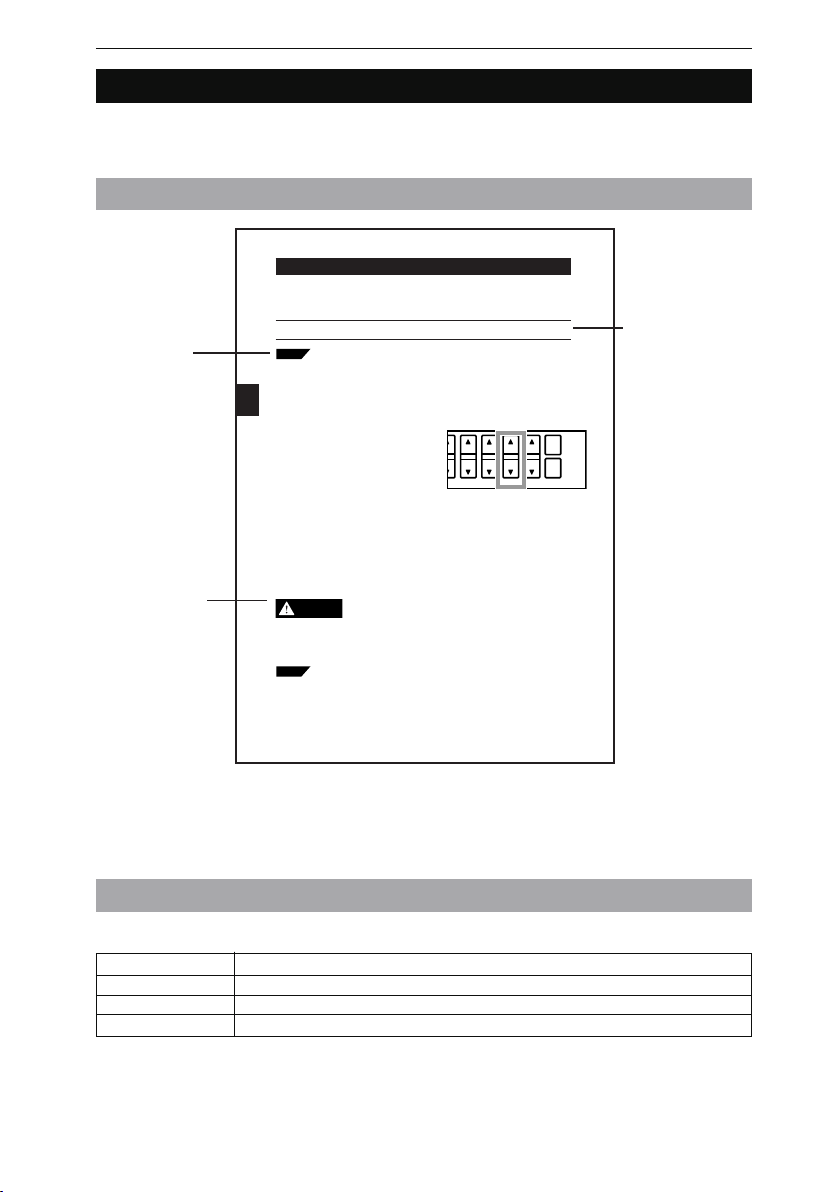
Chapter 3 Operation Control
Automatic Zero Function
The automatic zero function sets measuring values to zero (0.00000) instantly. This function is convenient for zero-point calibration for a variety of target. Furthermore,
master calibration is possible by using this function in combination with the offset function.
Tips: Describes
information that will
deepen the user’s
comprehension of
the manual along
with other useful
information.
Caution: Indicates
information that, if
not heeded, could
result in relatively
serious or minor
injury, damage to
the LS-7000 Series,
or faulty operation.
Note: This function will not be available while the controller is awaiting the result of
measurement, during which the LCD monitor will display “– – –. – – – –.”)
The automatic zero value will not be lost after the LS-7500 Series is turned
Tips
off. The automatic zero value for each program will be stored.
Automatic zero settings are made through the following functional components.
• Control panel
• External terminal
3
• RS-232C interface
■ Control Panel
If a single measuring value is displayed, an
automatic zero setting will be made for the
corresponding OUT number only.
If both measuring values are displayed, an
automatic zero setting will be made for the
selected OUT number on the screen.
1
Press the [ZERO] key once. Automatic
zero will be set.
To cancel the setting, press the [ZERO]
key again.
■ External I/O Terminal
Automatic zero will be set by short-circuiting the I/O, ZERO, and COM terminals on the
rear panel of the controller together.
Refer to Section 7 I/O Terminals on page 7-1 for details.
CAUTION
Tips
3-10
• Do not look at the LED light source for a long time.
The LED used as the light source is classified into class 1
according to IEC60825-1 standards. Basically the light beam of
the LED is safe, but do not look at the LED for a long time
Master Calibration with Offset Function (Automatic Offset Function)
Set the size of a master workpiece to an offset value and make an automatic
zero setting while measuring the master workpiece. Then the size of the
master workpiece will be displayed as an offset value. Refer to 3-3 Measurement of Outer Diameter and Width (with Two Measuring Heads) on page 3-4
for an application example.
Refer to Offset on page 5-43 for the offset function in detail.
AREA DISP
HOLD
ZERO
Note: Describes
items that need the
user’s attention in
order to prevent
mistakes in the
operation of the
LS-7000 Series.
❈ The above page sample is for your reference only. It does not coincide with any of
the actual pages of this manual.
Definition of Terms
This manual uses the following terms.
Term Description
LS-7000 Series Refers to the LS-7001 controller and the measuring head as a set.
Controller Refers to the LS-7001 controller.
Measuring head Refers to the LS-7010/LS-7030/LS-7070 measuring head.
v
Page 8

Optimum Measurement Methods
Refer to the following methods, and select the optimum measurement method according to
the type of target.
Measurement of Outer Diameter
of a Round Bar or Wire
Measurement of Average Outer
Diameter of Round Bar or Wire
Measurement of Sheet Width
D
Measurement of outer diameter and
width (with single measuring head)
(Page 2-2)
Measurement of Inner
Diameter of a Disc
Measurement of inner diameter and
clearance (Page 2-5)
Measurement of Connector
Pins and IC Pins
Y
X
Measurement of outer diameter and
width (with two measuring heads in X
and Y directions) (Page 2-3)
Measurement of Outer Diameter
and Eccentricity of a Roller
Measurement of outer diameter and
eccentricity (Page 2-6)
L
Measurement of outer diameter and
width (with two measuring heads for
larger objects) (Page 2-4)
Measuring Robot Movement
and Positioning of LCD Plate
Measurement of movement and
positioning (Page 2-7)
Measurement of pitch (Page 2-8)
vi
Page 9

Configuration of Manual
Chapter 1 Getting Started
Provides information on precautions and necessary preparations
required.
Chapter 2 Easy Setting Guide
Provides information on targets and settings for typical applications
respectively.
Chapter 3 Operation Control
Provides information on setting control items on the control panel while
the LS-7000 Series is in measurement operation.
Chapter 4 Function Settings
Provides information on the overview of program settings and setting
methods.
Chapter 5 Environment Settings
Provides information on basic operation settings.
Chapter 6 I/O Terminals
Provides information on the specifications of the I/O terminals and
timing charts.
1
2
3
4
5
6
Chapter 7 RS-232C
Provides information on how to connect external devices and the
communications function to operate the LS-7000 Series through the
external devices.
Chapter 8 Specifications
Provides the specifications, characteristics, and external dimensions of
the LS-7000 Series.
Chapter 9 Troubleshooting
Provides information on troubleshooting and error messages.
Appendix
Provides a list of options and the index of the manual.
7
8
9
Appendix
vii
Page 10

Measured va
between the r
setting. (See pa
LS-7001 Operation Map
Select the area (See page 3-4)
Press the Up or Down key to
select the area.
AREA
The selected area appears on the
AREA display.
POSITION monitor
The POSITION monitor is lit according to the
position and size of the target.
FOCUS monitor
The FOCUS monitor is lit according
to the distance between the
transmitter and receiver.
To make lit range changes, refer to
page 4-14.
Program Settings
Area, calibration, output, or option
setting:
Press the key and select the
item with key.
PROG
FUNC
AREA
1
2
FUNC
POSITION
FOCUS
ESCPROG
PRINT
ENT
No.
PROG No.
Environment setting:
Press the key while pressing
the key.
Set item selection:
Press the or key.
Set item cancellation:
Press the key.
Entering set item:
Press the key.
viii
FUNC
PROG
ESC
ENT
Program selection
Press the Up or Down key.
PROG No.
Page 11

OUT 1
OUT 2
HI
GO
LO
TIM
HI
GO
LO
HOLD
ZERO
LS-7000
Tolerance setting (See page 4-50)
Reference value mode
Upper limit setting:
Reference value setting:
Lower limit setting:
Press the
Press the
Press the
HI
GO
LO
Threshold setting
HI value setting:
HH value setting:
LO value setting:
LL value setting:
Press the
Press the
Press the
Press the
HI
HI
LO
LO
Value change while setting
LO
Press the key
below the value
HOLD
ZERO
flashing.
Hold function (See page 3-5)
key.
key.
key.
key.
key 2X.
key.
key 2X.
Measured value display selection
Press the Up or Down key.
DISP
Measured value display varies
between the reference value mode
and threshold mode for tolerance
setting. (See page 3-2)
Press the key.
HOLD
Auto zero function (See page 3-6)
Press the key.
To cancel the function, press the
ZERO
key again.
ZERO
ix
Page 12

Contents
Safety Precautions ..............................................................................................................i
Precautions for CE Markings ........................................................................................... iv
About this Manual .............................................................................................................. v
Page Configuration and Symbols .................................................................................... v
Definition of Terms .......................................................................................................... v
Optimum Measurement Methods .................................................................................... vi
Configuration of Manual .................................................................................................. vii
LS-7001 Operation Map .................................................................................................. viii
Contents.............................................................................................................................. x
Chapter 1 Getting Started
Outline and Features of LS-7000 Series ....................................................................... 1-2
System Applications ....................................................................................................... 1-3
Package Checks .............................................................................................................. 1-4
LS-7001 ....................................................................................................................... 1-4
LS-7010 ....................................................................................................................... 1-4
LS-7030 ....................................................................................................................... 1-4
LS-7070 ....................................................................................................................... 1-5
LS-C✱✱A ..................................................................................................................... 1-5
LS-S11 ......................................................................................................................... 1-6
Functions and Nomenclature ......................................................................................... 1-7
Controller ..................................................................................................................... 1-7
Measuring Head ........................................................................................................... 1-9
Mounting and Connection ............................................................................................ 1-11
Mounting the Measuring Head ................................................................................... 1-11
Mounting the Controller .............................................................................................. 1-13
Connection .................................................................................................................1-17
Turning AC Power Supply Stand On and Off .............................................................. 1-19
Measurement and Setting Overview ........................................................................... 1-20
Resetting to Initial Status .............................................................................................1-21
Chapter 2 Easy Setting Guide
Measurement of Outer Diameter and Width (with Single Measuring Head) .............. 2-2
Measurement of Outer Diameter and Width (with Two Measuring Heads)................. 2-3
Measurement of Outer Diameter and Width
(with Two Measuring Heads for Larger Objects) ..........................................................2-4
Measurement of Inner Diameter and Clearance ........................................................... 2-5
Measurement of Outer Diameter and Eccentricity ....................................................... 2-6
Measurement of Movement and Positioning ................................................................ 2-7
Measurement of Pitch .....................................................................................................2-8
Chapter 3 Operation Control
Selection of Measured Value Display ............................................................................ 3-2
Area Monitor ....................................................................................................................3-4
Hold Function ..................................................................................................................3-5
Automatic Zero Function................................................................................................ 3-6
Panel Lock Function ....................................................................................................... 3-7
Program Changes ........................................................................................................... 3-8
x
Page 13

Chapter 4 Function Settings
Flow of Program Settings ............................................................................................... 4-2
Default Values and Possible Setting Ranges ............................................................... 4-4
Copying Program Setting Details and Initialization ..................................................... 4-6
Area Settings ...................................................................................................................4-7
Area Selection .............................................................................................................. 4-9
Focus Monitor ............................................................................................................ 4-14
Area Check ................................................................................................................ 4-15
Difference Check........................................................................................................ 4-16
Function Output Selection .......................................................................................... 4-17
Change of Edge Detection Threshold ........................................................................ 4-18
Calibration Settings ...................................................................................................... 4-20
Calibration Type Selection ......................................................................................... 4-23
Logic Calibration Settings .......................................................................................... 4-23
Two-point Calibration Settings ................................................................................... 4-25
One-point Calibration Settings ................................................................................... 4-26
Initialization of Calibration .......................................................................................... 4-26
Output Settings ............................................................................................................. 4-28
Area Calculation ......................................................................................................... 4-30
Number of Averaging Measurements......................................................................... 4-31
Measuring Mode ........................................................................................................ 4-33
Offset ......................................................................................................................... 4-43
Analog Output Settings .............................................................................................. 4-44
Comparator Output Setting ........................................................................................ 4-47
Tolerance (LIMIT) Settings ........................................................................................... 4-50
Limit Range ................................................................................................................ 4-50
Limit Settings ............................................................................................................. 4-51
Hold Value Elimination ............................................................................................... 4-52
Option Settings ............................................................................................................. 4-54
Tolerance Mode (LIMITS)........................................................................................... 4-56
Timing Mode .............................................................................................................. 4-56
Display Unit ................................................................................................................ 4-57
Minimum Display Unit ................................................................................................ 4-58
I/O Mode .................................................................................................................... 4-59
Units, Default Minimum Values, and Setting Ranges ................................................. 4-60
Chapter 5 Environment Settings
Possible Environment Settings ...................................................................................... 5-2
Default Settings ............................................................................................................ 5-2
Changing Environment Settings .................................................................................. 5-3
Flow of Environment Setting Display ........................................................................... 5-4
Details of Environment Settings .................................................................................... 5-5
Program ....................................................................................................................... 5-5
RS-232C ...................................................................................................................... 5-7
Head .......................................................................................................................... 5-10
Beep ........................................................................................................................... 5-12
Panel Lock ................................................................................................................. 5-13
xi
Page 14

Chapter 6 I/O Terminals
Nomenclature and Functions of I/O Terminals ............................................................. 6-2
Te r minal Block .............................................................................................................. 6-2
Connector I/O ............................................................................................................... 6-4
Functions ..................................................................................................................... 6-7
Electrical Specifications ............................................................................................... 6-9
Timing Chart ..................................................................................................................6-11
Chapter 7 RS-232C
Specifications .................................................................................................................. 7-2
Communication using Serial Commands ..................................................................... 7-4
Connecting to a PC/PLC Link Unit ............................................................................... 7-4
Connecting to KV Series .............................................................................................. 7-5
Outline of Command Formats ...................................................................................... 7-6
Measurement Serial Commands ................................................................................. 7-7
Setup Serial Commands ............................................................................................ 7-12
Serial Commands to check the LS Settings ............................................................... 7-19
Batch Commands ...................................................................................................... 7-20
Timing Chart .............................................................................................................. 7-21
ASCII Table ................................................................................................................ 7-22
Communication using an External Synchronous Trigger ......................................... 7-23
Chapter 8 Specifications
Specifications .................................................................................................................. 8-2
Controller ..................................................................................................................... 8-2
Measuring Head ........................................................................................................... 8-3
Optional Accessories ................................................................................................... 8-3
Characteristics ................................................................................................................ 8-4
Measurement Range and Accuracy ............................................................................. 8-4
Temperature Characteristics ........................................................................................8-5
Response Delay Time .................................................................................................. 8-6
Focus Characteristics................................................................................................... 8-6
Mode Specifications ....................................................................................................... 8-7
External Dimensions....................................................................................................... 8-8
Chapter 9 Troubleshooting
Troubleshooting Guide ................................................................................................... 9-2
Error Messages ............................................................................................................... 9-6
Appendix
List of Optional Accessories........................................................................... Appendix-2
Setting Record Sheet ....................................................................................... Appendix-3
Environment Setting Record Sheet ................................................................ Appendix-5
Index ................................................................................................................. Appendix-6
xii
Page 15

Chapter 1
Getting Started
This section provides information on the configuration of the
LS-7000 Series, precautions, and necessary preparations
required before operating the LS-7000 Series. Familiarize
yourself with this section before using the LS-7000 Series.
Outline and Features of LS-7000 Series .............................. 1-2
System Applications ............................................................. 1-3
Package Contents ................................................................ 1-4
Functions and Nomenclature ............................................... 1-7
Mounting and Connection .................................................. 1-11
Supply Stand On and Off ................................................... 1-19
Setting Overview ................................................................ 1-20
Resetting to Initial Status ................................................... 1-21
1-1
Page 16

Chapter 1 Getting Started
Outline and Features of LS-7000 Series
1
The LS-7000 Series is a high-speed, high-accuracy digital micrometer used for the dimensional measurement of objects without coming into contact with the objects. It is such a
versatile model that it has a wide range of applications including in-line measurement and
offline measurement.
■ Special Features
High-speed Sampling of 2400 Times per Second
Ensures high-speed sampling that is twice as fast as the sampling speed of conventional models. The continuous measurement of extruded products and the in-line
measurement of moving workpieces are possible.
Repeat Accuracy of ±0.15
μm
Incorporates the latest optical system, thus ensuring excellent repeat accuracy that is
twice as high as the accuracy of conventional models, thus supporting the manufacture
of high-precision products.
Connecting Two Measuring Heads for two-channel Simultaneous Measurement
Two measuring heads can be used in combination for the simultaneous measurement
of two targets.
Stable Detection of Transparent Objects with Threshold Change
The threshold change function supported by the DE processor makes it possible to
detect transparent objects stably.
■ Principle of Measurement
The high-intensity GaN green LED radiates light, which will be changed into uniform
parallel light through the special diffusion unit and collimator lens and emitted to the
target in the measuring range. Then the shadow image of the target will appear on the
HL-CCD (high-speed linear CCD) through the telecentric optical system. The output
incident signal of the HL-CCD will be processed by the DE (digital edge-detection)
processor in the controller and CPU. As a result, the dimensions of the target will be
displayed and output.
1-2
HL-CCD for
measurement use
Receiver Transmitter
A/D
conversion
Telecentric optical
system
Target
DE
processor
Controller
High-intensity GaN
green LED
Special diffusion unit
CPU
Collimator lens
Control input
Control output
BCD output
Analog output
RS-232C interface
Page 17

System Applications
Chapter 1 Getting Started
The LS-7000 Series has a wide range of applications when used in combination with
commercially available peripheral devices.
Printer
The results of measurement
are printed.
RS-232C
PC
Control values or measuring
values are retrieved over RS232C.
RS-232C
LS-7001
Programmable Logic
Controller
Control output and measured
values are retrieved and
programs for measurement
timing control are changed.
Comparator output
BCD output
RS-232C
Timing input
Auto zero input
Reset input
Program number selection
1
Comparator output
Indicator Light and Buzzer
Alarms are generated according to
the output of discrimination
results.
Analog output
Recorder
The results of
measurement are
recorded.
Timing input
Photoelectric Sensor or
Proximity Sensor
Timing input signals are sent
whenever objects are detected.
1-3
Page 18

Chapter 1 Getting Started
Package Checks
1
Check that nothing is missing from the LS-7000 Series package before use.
LS-7001
Controller Four Panel Mounting
Brackets
`
LS-7000 Series
User’s Manual
LS-7010
Measuring Head
Allen-head bolt
(Five, M3 x 45 with a washer)
Allen-head bolt
(Four, M4 x 20)
96M1613
1-4
LS-7030
Measuring Head
Allen-head bolt
(Six, M5 x 45 with a washer)
Allen-head bolt
(Four, M4 x 20)
Page 19

LS-7070
Chapter 1 Getting Started
Measuring Head
Allen-head bolt
(Six, M4 x 50 with a washer)
Allen-head bolt
(Four, M5 x 20)
LS-C✱✱A
Extension Cable (Cable between the controller and measuring head)
1
LS-C3A: 3-m cable
✱✱... LS-C10A: 10-m cable
✱✱... LS-C30A: 30-m cable
Up to two cables are connectable, provided that the
total length of the cables does not exceed 40 m.
1-5
Page 20

1
Chapter 1 Getting Started
LS-S11
Stand Unit Base Unit
Screws (Four, M4 x 8)
❈ Keyence ships each package with utmost care and attention. If there should be any
improper or damaged product, contact your Keyence representative.
1-6
Page 21

Functions and Nomenclature
Chapter 1 Getting Started
The following section provides information on the functions and nomenclature of the
controller and measuring head.
Controller
Control Panel
(Page 1-8, Control Panel)
Controller (Rear Side)
Connector I/O
Used for signal I/O
(Page 6-2, Section 6 I/O Pin)
Modular Connector
Used to connect the console connector
or RS-232C cable connector.
(Page 7-4, 7-5, Section 7 RS-232C)
Terminal Block
Used for signal I/O
(Page 6-2, Section 6 I/O Terminals)
1
Controller (Bottom)
Power Input Pins (24 VDC)
Provide 24 VDC power supply.
DC IN
Connect the LS-S11 AC Power Supply
Cable.
Extension Cable
Connect the cable between the controller and
the measuring head.
1-7
Page 22

1
Chapter 1 Getting Started
■ Control Panel
(1)
AREA
(3)
(4)
(5)
1
2
POSITION
FOCUS
OUT 1
OUT 2
HI
GO
LO
TIM
HI
GO
LO
(19)
(20)
(21)
(2)
(17)
(6)
(7)
FUNC
ESCPROG
PRINT
ENT
PROG No.
AREA DISP
HOLD
ZERO
LS-7000
(16)
(15)
(8) (10) (9) (11) (12) (18) (13) (14)
(1) Main display: The measured value is displayed. Refer to Selection
of Measured Value Display on page 3-2.
(2) Sub display: Used to display tolerance or measured values while
the LS-7000 Series is in measuring operation. The set
value is displayed while in value setting. Refer to
Selection of Measured Value Display on page 3-2.
(3) Area monitor display: The number of the selected area is displayed. Refer
to Area Monitor on page 3-4.
(4) Position display: The position of the target in the selected area is
displayed. Refer to Area Monitor on page 3-4.
(5) Focus display: The focus status of the selected area is displayed.
Refer to Area Monitor on page 3-4.
(6)
(Setting) key: Press this key to set program details. Refer to
PROG
Program Changes on page 3-8.
(7)
(Function) key: Press this key to set the setting item. Refer to Section
FUNC
4 Function Settings.
(8)
(9)
(10)
/ key: Press the Up or Down key to select the set item.
key: Press this key to finish the present setting.
ESC
key: Press this key to enter the set item or print the meas-
ENT
ured value from the printers.
(11) Program number display: The selected program number is displayed.
(12) Program selection key: Press this key to select the program number when
measuring. (Page 3-8, Program Change)
(13) Area monitor selection key: Press this key to select the area number when
measuring. (Page 3-4, Area Monitor)
1-8
Page 23

Chapter 1 Getting Started
(14) Display selection key: Press this key to select the main display or sub
display when measuring. (Page 3-2, Switching
Display Screen)
ZERO
(15)
key: Press this key to select the auto zero function. (Page
3-6, Automatic Zero Function)
(16)
key: Press this key to select the hold function. (Page 3-5,
HOLD
Hold Function)
(17)
, GO, and LO keys: Press these keys to make tolerance settings. (Page 4-
HI
50, Limit Setting)
and keys: Press these keys to select the set value or item.
(18)
(19) Output selection display: Indicates whether the measured value on the main
display is OUT1 or OUT2.
(20) Comparator result display: Displays the comparator result of the main display.
(21) Timing display: Lit when timing input into the main display turns ON.
Measuring Head
LS-7010
Multi-purpose
Mounting Holes
A fixture for targets can
be attached.
Receiver (R Head)
Receives light from
the transmitter.
Extension Cable
Connected to the controller.
Cover Glass
Transmitter (T Head)
Emits light for
measurement.
TR Base
Used to mount the
transmitter and receiver.
TR Cables
Used to connect the transmitter
Mounting Holes
Used to mount the
measuring head.
1
1-9
Page 24

1
Chapter 1 Getting Started
LS-7030
Multi-purpose
Mounting Holes
A fixture for targets can
be attached.
Receiver (R Head)
Receives light from
the transmitter.
Extension Cable
Connected to the controller.
LS-7070
Multi-purpose
Mounting Holes
A fixture for targets can
be attached.
Receiver (R Head)
Receives light from
the transmitter.
Cover Glass
Cover Glass
TR Base
Used to mount the
transmitter and receiver.
TR Cables
Used to connect the
transmitter and receiver.
Mounting Holes
Used to mount the measuring head.
Transmitter (T Head)
Emits light for
measurement.
Transmitter (T Head)
Emits light for
measurement.
1-10
Mounting Holes
Used to mount the measuring head.
Extension Cable
Connected to the controller.
TR Base
Used to mount the
transmitter and receiver.
TR Cables
Used to connect the
transmitter and receiver.
Page 25

Chapter 1 Getting Started
Mounting and Connection
Mount the measuring head and the controller, and connect them with the cables.
■ Mounting the Measuring Head
The measuring head can be mounted with or without the TR base employed, according
to the type of targets and operating environment.
The following section provides information on how to mount the measuring head with or
without the TR base employed, along with mounting conditions required.
■ Mounting the Controller
Mount the controller to panels, such as control or operation panels, or to the LS-S11 AC
Power Supply Stand. The LS-S11 Power Supply Stand is sold separately.
■ Connection
After the measuring head and the controller are mounted, connect them with the cables.
Mounting the Measuring Head
■ Mounting Restrictions
The transmitter and receiver must abide by the following restrictions when the measuring head is mounted.
Vertical Position Mismatching Angle Mismatching
1
±1 mm max.
±1 mm max.
The values are the same
for LS-7010, LS-7030, and
LS-7070.
TransmitterReceiver
TransmitterReceiver
±0.25° max
±0.25° max
±0.25° max
±0.25° max
TransmitterReceiver
TransmitterReceiver
TransmitterReceiver
TransmitterReceiver
1-11
Page 26

1
Chapter 1 Getting Started
■ With TR Base
The transmitter and receiver are mounted to the TR base at the time of shipment. This
section provides how to install the transmitter and receiver (LS-7030 in this case) that
are mounted on the TR base.LS-7010 and LS-7070 can also be installed in the same
way.
Use the four, M4x20 Allen-head bolts, which
are provided with the package, to mount the
TR base. To mount the TR base with the
bolts on the surface of the TR base, use the
mounting holes on the surface.
To mount the TR base with the bolts on the
back of the TR base, use the 10-mm-deep
M4 (10-mm-deep M5 for LS-7070) mounting
holes on the back.
■ Without TR Base
Take the following steps to use the transmitter and receiver (LS-7030 in this case) after
dismounting them from the TR base. LS-7010 and LS-7070 can also be used in the
same way.
1 Loosen the bolts on the back of the
TR base and remove the measuring
head.
1-12
2 Mount the measuring head.
Use the side mounting holes on the
transmitter and receiver as shown in the
illustration. Mount them with the Allenhead bolts provided with the package.
Page 27

Use the 5-mm-deep M4 bottom mounting
holes of the transmitter and receiver as
shown in the illustration.
Mounting the Controller
■ Mounting Restrictions
Be aware of the following items when mounting the controller.
Chapter 1 Getting Started
1
CAUTION
Note: • For the maintenance, operability, and ventilation of the LS-7000
• Do not install the controller upside down.
• Do not block the ventilation louver. Otherwise, the interior heat
may cause the controller to malfunction.
Series, separate the controller as far as possible from peripheral structures or parts.
• The mounting angle must abide by the following restrictions.
30˚
Side
Display
panel
• Check that the controller will not be exposed to the heat radiation of peripheral devices.
• Separate the controller as much as possible from devices with
arc generation, such as electromagnetic switches or non-fuse
breakers.
1-13
Page 28

1
Chapter 1 Getting Started
■ Mounting to Panel
The controller can be mounted to control panels with the mounting brackets provided
with the package. Arrange the following panel mounting dimensions.
207
+1
169
0
+1
124
0
200
Unit: mm
1 Mount the controller from the front
side of the panel.
1-14
2 Attach resin caps to the mounting
brackets.
3 Insert the mounting brackets to the
four mounting holes on the side of
the controller respectively.
Mounting holes
Mounting holes
Page 29

4 Secure the mounting brackets with a
Phillips screwdriver.
Chapter 1 Getting Started
1
CAUTION
• Tighten the mounting screws to a maximum torque of 0.4 Nm.
Do not tighten up the mounting screws excessively, otherwise
the panel or controller casing may be deformed.
• Do not remove the gasket, otherwise the controller will not
satisfy IP64 conditions.
■ Mounting to AC Power Supply Stand
The following section provides information on how to mount the controller to the AC
power supply stand (sold separately). The AC power supply stand consists of a stand
unit and base unit. Mount the controller to the stand unit first. Connect the power supply
cable and extension cable (i.e., the cable between the controller and measuring head).
Then mount them to the base unit.
1 Remove the gasket around the
controller.
Gasket
2 Mount the controller to the stand.
Use the two screws provided with the
package and secure the controller on the
side.
The stand must be located
on the groove from which
the gasket was removed.
Secure these
potions with screws.
1-15
Page 30

1
Chapter 1 Getting Started
3 Connect the cable between the con-
troller and measuring head.
If only a single measuring head is used,
connect the cable to the HEAD1 connector.
Cable between
controller and
measuring head
4 Connect the power supply cable of
the AC power supply stand to the
controller.
5 Mount the stand unit to the base unit.
Mount the stand unit with the two screws
provided with the package.
1-16
(2) Lean the stand unit in the
direction indicated by the
arrow. Pay utmost attention so
that the connected cable will
not be caught by the stand unit.
(1) Lean the stand unit in the
front direction and insert
the tab.
(3) Secure these portions
with screws.
Page 31

Chapter 1 Getting Started
Tips
The back of the AC power supply
stand has legs. Erect the legs and
use the AC power supply stand if
required.
Connection
Connect the measuring head, controller, and power supply with the cables.
Do not supply power to the controller while connecting the
CAUTION
Make the following three connections.
• Transmitter and Receiver: Connect the cables from the transmitter and receiver
• Measuring head and controller: Connect the cable between the controller and measur-
• Power supply cable: Supply 24 VDC to the controller directly or through the
cables. If the AC power supply stand is used, turn off the AC
power supply stand while connecting the cables. The measuring head, controller, or peripheral devices may be damaged if
power is supplied while connecting the cables.
respectively.
ing head.
AC power supply stand.
LS-7001
1
KZ-U3 24-VDC Power Supply
(Optional)
Power supply cable to the AC
power supply stand
Cable between controller
and measuring head
(LS-C3A/LS-C10A/LS-C30A)
Up to two cables are connectable,
provided that the total length of
the cables does not exceed 40 m.
Cable between controller
and measuring head
(LS-C3A/LS-C10A/LS-C30A)
Up to two cables are connectable,
provided that the total length of
the cables does not exceed 40 m.
Measuring head
(LS-7010/LS-7030/LS-7070)
Measuring head
(LS-7010/LS-7030/LS-7070)
Cable between transmitter and receiver
(OP-42182/OP-42183) (Optional)
Up to two cables are connectable,
provided that the total length of
the cables does not exceed 6 m.
1-17
Page 32

1
Chapter 1 Getting Started
■ Transmitter and Receiver
Connect the cables of the transmitter
and receiver respectively.
Connect both connectors so that the
notched part of each connector will coincide
with each other in position.
Receiver side
Transmitter side
■ Measuring Head and Controller
Connect the cables of the controller and
the measuring head.
Connect both connectors so that the
notched part of each connector will coincide
with each other in position.
Measuring
Controller side
head side
■ Power Supply Cable
Supply 24 VDC to the controller through I/O terminals 1 and 2 on the rear panel of
the controller. Secure the wires to the terminals with a Phillips screwdriver.
● Using AC Power Supply Stand (Sold
Separately):
Connect the output cable of the AC
power supply stand to the DC IN connector of the controller. Then connect
the AC cord provided with the AC power
supply stand to the electric outlet.
Turning AC Power
1-18
24 VDC
Page 33

Supply Stand On and Off
Chapter 1 Getting Started
This section provides information on how to turn the AC power supply stand on and off.
■ Turning Power On
1 Turn on the POWER switch on the
rear panel of the AC power supply
stand.
■ Turning Power Off
1 Turn off the POWER switch on the
rear panel of the AC power supply
stand.
Measurement and
1
1-19
Page 34

Chapter 1 Getting Started
Setting Overview
1
The LS-7000 Series is in measurement operation according to a variety of settings. The
following section provides information on each mode in detail and how to switch between
modes.
Power
On
RUN Mode
POSITION
AREA
1
2
FOCUS
Measures according to the set
program.
(See Section 3 Operation Control on
page 3-1)
PROGPROG
HI
GO
LO
OUT 1
OUT 2
HI
GO
LO
TIM
Press the key
while pressing the
FUNC
key.
PROG
Tolerance Setting
GO
HI
OUT 1
OUT 2
HI
The above keys
GO
LO
can be pressed to
TIM
make tolerance
HI
settings whether or
not the LS-7000
GO
Series is in
measurement
LO
operation.
(See Section 4 Tolerance(LIMIT)
Settings on page 4-50)
PROG
LO
Environment Settings
Make basic settings for the
operation of the LS-7000
Series.
(See Section 5 Environment
Settings on page 5-1)
Program Settings
Settings for measurement are registered as programs. The following settings
are possible.
• Area Setting
Set the measuring part.
• Compensation Setting
Set the compensation detail of errors in measurement.
• Output Setting
Set the processing and output details of the measuring value.
• Option Setting
Set the display unit and other items.
See Section 4 Function Settings on page 4-1.
The LS-7000 Series will be reset to the initial status by turning
the LS-7000 Series ON with the key pressed. (Page 1-21)
ZERO
1-20
Page 35

Resetting to Initial Status
Chapter 1 Getting Started
The following section provides information on how to reset all the programs and environment settings to factory-set values.
Tips
Refer to 5-2 Resetting All Programs on page 5-5 if the resetting of only the
programs to factory-set values is required.
1 Turn on the LS-7000 Series with the
ZERO
key pressed.
This display will appear when the LS-
AREA DISP
HIGH-ACCURACY CCD MICROMETER
HOLD
ZERO
7000 Series is turned ON.
POSITION
AREA
1
2
FOCUS
2 Press the or key and select
Yes.
3 Press the
ENT
key after the initializa-
tion of the LS-7001 is confirmed.
FUNC
ESCPROG
PRINT
ENT
1
OUT 1
OUT 2
HI
GO
LO
TIM
HI
GO
LO
1-21
Page 36

1
Chapter 1 Getting Started
MEMO
1-22
Page 37

Chapter 2
Easy Setting Guide
The LS-7000 Series is used for a variety of measurement
applications if the LS-7000 Series is set properly. This section
provides information on targets and settings for typical
applications respectively.
Measurement of Outer Diameter and Width
(with Single Measuring Head) ............................................. 2-2
Measurement of Outer Diameter and Width
(with Two Measuring Heads) ............................................... 2-3
Measurement of Outer Diameter and Width
(with Two Measuring Heads for Larger Objects) ................. 2-4
Measurement of Inner Diameter and Clearance ................. 2-5
Measurement of Outer Diameter and Eccentricity .............. 2-6
Measurement of Movement and Positioning ....................... 2-7
Measurement of Pitch ......................................................... 2-8
2-1
Page 38

2
Chapter 2 Easy Setting Guide
Measurement of Outer Diameter and Width (with Single Measuring Head)
In the following example, a single measuring head is used to measure the outer diameter
of an object in one direction. The result of measurement is displayed as OUT1.
D
Measures the outer diameter in one direction.
■ Set Values
Set item
Area setting
Calibration
Output
setting
Tolerance setting
AREA
Operation
Averaging
Measuring mode
Offset
AREA 1
Head 1 DIA
Make settings if required.
OUT 1 OUT 2
A1: 1.0
A2: OFF
Select the value according to the line speed.
Normal
No settings are required.
Set the upper and lower limit values.
Set value
AREA 2
No settings are required.
No settings are required.
■ Reference
2-2
Area Settings (Page 4-7)
Calibration Settings (Page 4-20)
Output Settings (Page 4-28)
Tolerance Settings (Page 4-50)
Page 39

Chapter 2 Easy Setting Guide
Measurement of Outer Diameter and Width (with Two Measuring Heads)
In the following example, two measuring heads are used to measure the average outer
diameter of an object in two directions. The measurement of the object in two directions
ensures high accuracy. The result of measurement is displayed as OUT1.
Y
X
X+Y
D=
2
Measures the outer diameter in two directions.
2
■ Set Values
Set item
Area setting
Output
setting
Tolerance setting
AREA
Calibration
Operation
Averaging
Measuring mode
Offset
■ Reference
Area Settings (Page 4-7)
Calibration Settings (Page 4-20)
Output Settings (Page 4-28)
Tolerance Settings (Page 4-50)
Set value
AREA 1
Head 1 DIA
Make settings if required.
OUT 1 OUT 2
A1: 0.5
A2: 0.5
Select the value according to the line speed.
Normal
No settings are required.
Set the upper and lower limit values.
Head 2 DIA
No settings are required.
AREA 2
2-3
Page 40

2
L= (X+Y)
Chapter 2 Easy Setting Guide
Measurement of Outer Diameter and Width (with Two Measuring Heads for Larger Objects)
A sheet cannot be located in the measuring area of a single measuring head if the width or
diameter of the sheet is excessively large. In that case, the sheet can be measured with
two measuring heads as shown below with the automatic zero function and the master
workpiece used. The result of output is displayed as OUT1.
L
■ Set Values
■ Reference
2-4
Set item
Area setting
Output
setting
Tolerance setting
Automatic Zero Function: Measure the master workpiece and make automatic zero
settings. (Page 3-6)
Area Settings (Page 4-7)
Calibration Settings (Page 4-20)
Output Settings (Page 4-28)
Tolerance Settings (Page 4-50)
AREA
Calibration
Operation
Averaging
Measuring mode
Offset
Head 1 B-EDGE
Make settings if required.
A1: –1.0
A2: –1.0
Select the value according to the line speed.
Normal
Input the size of master workpiece.
Set the upper and lower limit values.
AREA 1
OUT 1 OUT 2
Set value
AREA 2
Head 2 B-EDGE
No settings are required.
Page 41

Chapter 2 Easy Setting Guide
Measurement of Inner Diameter and Clearance
In the following example, the inner diameter of the workpiece is measured while the
workpiece moves. The maximum value measured is taken as the inner diameter of the
workpiece. The result of output is displayed as OUT1.
2
■ Set Values
Set item
Area setting
Output
setting
Tolerance setting
AREA
Calibration
Operation
Averaging
Measuring mode
Offset
■ Reference
Area Settings (Page 4-7)
Calibration Settings (Page 4-20)
Output Settings (Page 4-28)
Tolerance Settings (Page 4-50)
Set value
AREA 1
Head 1 SEG
(001-E, 002-E)
Make settings if required.
OUT 1 OUT 2
A1: 1.0
A2: OFF
Select the value according to the line speed.
Peak hold
No settings are required.
Set the upper and lower limit values.
No settings are required.
No settings are required.
AREA 2
2-5
Page 42

2
Chapter 2 Easy Setting Guide
Measurement of Outer Diameter and Eccentricity
In the following example, the outer diameter and eccentricity of the roller is measured while
the roller moves. The outer diameter is displayed as OUT1, and the eccentricity is displayed as OUT2.
Eccentricity
Outer diameter
■ Set Values
Set item
Area setting
Output
setting
Tolerance setting
AREA
Calibration
Operation
Averaging
Measuring mode
Offset
■ Reference
Area Settings (Page 4-7)
Calibration Settings (Page 4-20)
Output Settings (Page 4-28)
Tolerance Settings (Page 4-50)
Set value
AREA 1
Head 1 DIA Head 1 T-EDGE
Make settings if required.
OUT 1 OUT 2
A1: 1.0
A2: OFF
1
Average hold
No settings are required No settings are required
Set the upper and lower limit values.
A1: OFF
A2: 1.0
Select the value according to the rpm.
Peak-to-peak hold
AREA 2
2-6
Page 43

Chapter 2 Easy Setting Guide
Measurement of Movement and Positioning
In the following example, the movement or position of the workpiece is measured. The
result of output is displayed as OUT1.
■ Set Values
Set item
Area setting
Calibration
Output
setting
Tolerance setting
AREA
Operation
Averaging
Measuring mode
Offset
AREA 1
Head 1 SEG.
(000-E, 002-E)
Make settings if required.
OUT 1 OUT 2
A1: 1.0
A2: OFF
Select the value according to the line speed
Normal
No settings are required
Set the upper and lower limit values.
Set value
AREA 2
No settings are required
No settings are required
2
■ Reference
Area Settings (Page 4-7)
Calibration Settings (Page 4-20)
Output Settings (Page 4-28)
Tolerance Settings (Page 4-50)
2-7
Page 44

2
Chapter 2 Easy Setting Guide
Measurement of Pitch
The single pitch of connectors pins or IC pins is measured by the LS-7000 Series. Furthermore, multiple pitch of pins is measured with the program function or RS-232C interface
used.
The center pitches of the two portions
are measured at a time.
■ Set Values
■ Reference
2-8
Set item
Area setting
Calibration
Output
setting
Tolerance setting
AREA
Operation
Averaging
Measuring mode
Offset
Head 1 SEG
(002-P, 004-P)
Make settings if required.
A1: 1.0
A2: OFF
Select the value according to the line speed
Sample hold 1/2
No settings are required
Set the upper and lower limit values.
RS-232C (Page 7-1)
Area Settings (Page 4-7)
Calibration Settings (Page 4-20)
Output Settings (Page 4-28)
Tolerance Settings (Page 4-50)
Set value
AREA 1
Head 1 SEG
(004-P, 006-P)
OUT 1 OUT 2
A1: OFF
A2: 1.0
Select the value according to the line speed
Sample hold 1/2
No settings are required
AREA 2
Page 45

Chapter 3
Operation Control
This section provides information on setting control items on
the control panel while the LS-7000 Series is in measurement
operation.
Selection of Measured Value Display ......................... 3-2
Area Monitor................................................................ 3-4
Hold Function .............................................................. 3-5
Automatic Zero Function ............................................. 3-6
Panel Lock Function.................................................... 3-7
Program Changes ....................................................... 3-8
3-1
Page 46

3
Chapter 3 Operation Control
Selection of Measured Value Display
Displayed values on the main and sub displays can be switched. The main display can
display the measured results of OUT1 (or OUT2) and the sub display can display tolerance
comparator set values or measured values simultaneously. Four display types can be
selected in two tolerance modes (i.e., the reference value mode and threshold mode).
Refer to Option settings on page 4-54 for the selection of the reference value mode or
threshold mode.
Press the DISP (display) key and select
the value or item.
The following displayed values can be
selected.
AREA DISP
■ Tolerance Mode with Reference Value
HOLD
ZERO
OUT 1
OUT 2
HI
GO
LO
POSITION
AREA
1
2
FOCUS
TIM
HI
GO
LO
OUT1 is lit.
OUT1 measured value is displayed.
OUT1 upper limit is displayed.
OUT1 reference value is displayed.
OUT1 lower limit is displayed.
DISPDISP
OUT 1
OUT 2
HI
GO
LO
POSITION
AREA
1
2
FOCUS
TIM
HI
GO
LO
OUT2 is lit.
OUT2 measured value is displayed.
OUT2 upper limit is displayed.
OUT2 reference value is displayed.
OUT2 lower limit is displayed.
DISPDISP
OUT 1
OUT 2
HI
GO
LO
POSITION
AREA
1
2
FOCUS
TIM
HI
GO
LO
OUT1 is lit.
OUT1 measured value is displayed.
OUT2 measured value is displayed.
DISPDISP
OUT 1
OUT 2
HI
GO
LO
POSITION
AREA
1
2
FOCUS
TIM
HI
GO
LO
OUT2 is lit.
OUT2 measured value is displayed.
OUT1 measured value is displayed.
3-2
Page 47

■ Tolerance Mode with Threshold
Chapter 3 Operation Control
OUT 1
OUT 2
HI
GO
LO
POSITION
AREA
1
2
FOCUS
TIM
HI
GO
LO
Out 1 is lit.
Out 1 measured value is displayed.
Out 1 HI value is displayed.
Out 1 LO value is displayed.
DISPDISP
OUT 1
OUT 2
HI
GO
LO
POSITION
AREA
1
2
FOCUS
TIM
HI
GO
LO
Out 2 is lit.
Out 2 measured value is displayed.
Out 2 HI value is displayed.
Out 2 LO value is displayed.
3
DISPDISP
OUT 1
OUT 2
HI
GO
LO
POSITION
AREA
1
2
FOCUS
TIM
HI
GO
LO
Out 1 is lit.
Out 1 measured value is displayed.
Out 2 measured value is displayed.
DISPDISP
OUT 1
OUT 2
HI
GO
LO
POSITION
AREA
1
2
FOCUS
TIM
HI
GO
LO
Out 2 is lit.
Out 2 measured value is displayed.
Out 1 measured value is displayed.
Tips
The displayed settings are saved in the program settings.
3-3
Page 48

3
Chapter 3 Operation Control
Area Monitor
The area monitor display can be used to confirm the insertion positions of the targets in
AREA1 or AREA2 to be selected.
Press the AREA key on the control panel
and select the area.
The following items will be displayed when
the area is selected.
AREA DISP
The selected area number is lit.
HOLD
ZERO
Tips
AREA
1
2
POSITION
POSITION Monitor
The POSITION monitor is lit
according to the position and size of
the target in the CCD scanning
range.
FOCUS
FOCUS monitor
The FOCUS monitor is lit according
to the distance between the
receiver and target.
AREA
1
2
AREAAREA
POSITION
FOCUS
The displayed settings are saved in the program settings.
3-4
Page 49

Chapter 3 Operation Control
Hold Function
Measured values can be held and displayed. Furthermore, measuring mode combinations
allow the measurement of a variety of values, such as maximum and minimum values. The
types of measured values held vary with the measuring mode.
Refer to Measuring Mode on page 4-33 for details.
Measured values are held and displayed through the following functional components.
• Control panel
• External I/O terminals
• RS-232C interface
■ Control Panel
If either the OUT1 or OUT2 measured value is displayed, the displayed value will be
held. If both OUT1 and OUT2 measured values are displayed, both values will be held.
3
Press the
When the measured value is held, the TIM
indicator on the right-hand side of the main
display will be lit. To cancel the hold status,
press the
Tips
key on the control panel.
HOLD
key again.
HOLD
By pressing the
measured value kept on hold will
be reset.
ESC
key, the
HOLD
ZERO
AREA DISP
■ External I/O Terminals
Measured values will be held by short-circuiting the timing input terminal and COM
terminal together on the rear panel of the controller.
Refer to Section 6 I/O Terminals on page 6-1 for the external input terminals to be used.
■ RS-232C Interface
Commands sent by external devices through the RS-232C interface make it possible to
put measured values on hold.
Refer to Section 7 RS-232C on page 7-1 for the commands in detail.
3-5
Page 50

Chapter 3 Operation Control
Automatic Zero Function
The automatic zero function sets measured values to zero (0.00000) instantly. This function
is convenient for zero-point calibration for a variety of targets. Furthermore, master calibration is possible by using this function in combination with the offset function.
3
Note: This function will not be available while the controller is awaiting the result of
Tips
Automatic zero settings are made through the following functional components.
• Control panel
• External terminal
• RS-232C interface
measurement, during which the monitor will display “– – –. – – – –.”)
The automatic zero value will not be lost after the LS-7000 Series is turned
off. The automatic zero value for each program will be stored.
■ Control Panel
When only the OUT1 or OUT2 measured value is displayed, auto zero setting is made
for the displayed value. If both OUT1 and OUT2 values are displayed, auto zero setting
is made for both values.
Press the
Press the
zero setting.
ZERO
key on the control panel.
key again to cancel the auto
ZERO
HOLD
ZERO
AREA DISP
■ External I/O Terminal
Auto zero setting is made by short-circuiting the ZERO and COM terminals on the rear
panel of the controller. Refer to Section 6 I/O Terminals on page 6-1 for details.
Note: Automatic zero cannot be canceled through the external I/O terminals.
■ RS-232C Interface
Commands sent by external devices through the RS-232C interface make it possible to
set or cancel the automatic zero function. Refer to Automatic Zero ON/OFF on page 710 for details.
Tips
3-6
Master Calibration with Offset Function (Automatic Offset Function)
Set the size of a master workpiece to an offset value and make an automatic
zero setting while measuring the master workpiece. Then the size of the
master workpiece will be displayed as an offset value. Refer to Measurement
of Outer Diameter and Width (with Two Measuring Heads) on page 2-4 for an
application example. Refer to Offset on page 4-43 for the offset function in
detail.
Page 51

Chapter 3 Operation Control
N
O
Panel Lock Function
The panel lock function is used to lock the control panel so that no key input will be enabled. As a result, there will be no risk of making setting changes with careless key input.
Panel Lock Types
The following types of panel locks are possible with the PAN-LOC settings as environment
settings. Refer to Panel Lock on page 5-13 for details.
• Set the panel lock type to ALL: All keys will be locked.
• Set the panel lock type to PART: All keys excluding the DISP and AREA keys for the
display change function and
for the tolerance setting function and
locked. Select this type if you make tolerance changes
frequently without changing any other setting.
, GO, and LO keys
HI
key will be
HOLD
3
Panel Lock Display
The decimal in the PROG No. display will flash
while the panel is locked.
Tips
The panel lock status will not be
lost after the LS-7000 Series is
C
T
T
PROG No.
turned off or program number
changes are made.
Panel lock settings are made through the following functional components.
• Control panel
• RS-232C interface
■ Control Panel
Press the and keys on the
control panel together for 2 seconds.
To cancel the panel lock status, repeat the
FUNC
ESCPROG
PRINT
ENT
above.
■ RS-232C Interface
Commands sent by external devices through the RS-232C interface make it possible to
set or cancel the panel lock function. Refer to Panel Lock ON/OFF on page 7-11.
PR
3-7
Page 52

3
Chapter 3 Operation Control
Program Changes
The following section provides information on how to call 16 programs saved in the LS7000 Series.
Names and Number of Programs
The selected program is displayed on the
display monitor next to the [PROGRAM No.]
key.
It is possible to register 16 alphanumeric
characters (i.e., 0 through 9 and A through F)
for program numbers.
Programs are selected through the following
functional components.
• Control panel
• External I/O terminals
• RS-232C interface
C
NT
T
PROG No.
Note: The operation method varies with the P-SELECT setting as an environmental
setting. Refer to Program on page 5-5 for environment settings in detail.
P-SELECT setting Operation method
PANEL
TERMINAL
■ Control Panel
Press the [PROGRAM No.] key ( or
key) on the control panel.
The program numbers will be displayed in
sequence by pressing the key repeatedly.
Control panel/RS-232C interface
I/O terminals (P1 through P4)
ESC
PRINT
ENT
PROG No.
■ External I/O Terminals
External I/O terminals P1 through P4 on the rear panel of the controller can be used for
program selection. Refer to Section 6 I/O Terminals on page 6-1 for external I/O terminals to be used and program numbers in detail.
■ RS-232C Interface
Commands sent by external devices through the RS-232C interface make it possible to
select programs. Refer to PROGRAM No. on page 7-11 for the RS-232C interface in
detail.
3-8
Page 53

Chapter 4
Function Settings
The LS-7000 Series is available to the measurement of a
variety of items by making setting changes. These settings
can be registered as programs that can be used whenever
required. This section provides information on the overview of
program settings and setting methods.
Flow of Program Settings ............................................4-2
Default Values and Possible Setting Ranges.............. 4-4
Copying Program Setting Details and Initialization ..... 4-6
Area Settings............................................................... 4-7
Calibration Settings ................................................... 4-20
Output Settings ......................................................... 4-28
Tolerance (LIMIT) Settings ........................................ 4-50
Option Settings.......................................................... 4-54
4-1
Page 54

Chapter 4 Function Settings
Outp
Me
Optio
Flow of Program Settings
The following section provides information on the types and flows of program settings
available to the LS-7000 Series along with the relationship between the program settings
and external I/O.
4
Area Settings
(See page 4-7)
Measuring head Selection
Measuring head 1 (HEAD1)
Measuring head 2 (HEAD2)
Area Selection
Optional Settings
DIA
T-EDGE
B-EDGE
SEG
Select the number of
edges and mode (E/P)
■
Focus monitor
■
Area check
■
Difference check
■
Function output
■
Edge detection threshold
Averaging
number
Difference
value
Area 1
Area 2
Calibration Settings
(See page 4-20)
Calibration Settings (Optional)
■
Calibration mode selection
Logic calibration
Two-point calibration
One-point calibration
■
Calibration Value Initialization
Environment Settings
■
Program
■
RS-232C
■
Head
4-2
(See page 5-1)
■
■
Buzzer
Panel lock
Page 55

Chapter 4 Function Settings
Output Settings
(See page 4-28)
Optional Settings
■
Area calculation
■
Averaging number
■
Offset
(in combination with the automatic zero function)
Measuring Mode Settings
Output Settings
■
Analog output settings
Scaling (Reference value/Threshold)
Analog update mode
Output waiting voltage
■
Comparator output settings
Strobe output
Output logic
Off-delay time
OUT1
OUT2
External I/O
ZERO
TIMING
RESET
Analog output
Comparator output
Function output
4
Option Settings
■
Tolerance mode
Reference value
Threshold
(See page 4-54)
■
Unit
mm
μm
inch
mil
■
Minimum display unit
■
I/O mode
SUB
BCD
BCD output
4-3
Page 56

4
Chapter 4 Function Settings
Default Values and Possible Setting Ranges
The following programs settings are made by default.
Items in parentheses indicate what is displayed on the monitor.
■ Area Settings (AREA) (Page 4-7)
Item
Measuring head selection (HEAD No.)
Area (AREA)
Focus monitor (FOCUS)
Area check (A-TEST)
Difference
check (DIFF)
Function output setting (FUNCTION)
Edge detection threshold (LEVEL)
Averaging number (AVE)
Difference value
■ Calibration Settings (CALIB) (Page 4-20)
Item
Calibration mode (CAL-MODE)
T1-A/T1-B/T2-A/T2-B
Default
1
DIA
5
OFF
1
1000
FOCUS
50
Default
THEORY
Possible setting range
1, 2
Diameter (DIA)
Top edge (T-EDGE)
Bottom edge (B-EDGE)
Segment (SEG)
Specified SEG edge number: -127 to +127
SEG mode: Edge (E) or Pitch (P)
0 to 9
OFF (No area check), 2 to 127
1, 2, 4, 8, 16
1 to 9999 (in μm, mm, inch, or mil)
Focus monitor (FOCUS),
Area check (A-TEST),
Difference check (DIFF)
10 to 99
Possible setting range
Logic calibration (THEORY),
2-point calibration (2-TARGET),
or 1-point calibration (1-TARGET)
–99.99995 to +99.99995mm ❈
■ Tolerance Settings (LIMIT) (Page 4-50)
Item Default
HH output range (HH)
Threshold
mode
(TOL)
Reference
value mode
(DEV)
HI output range (HI) +30.00000
LO output range (LO) 0.00000
LL output range (LL) -10.00000
HOLD-H OFF
HOLD-L OFF
STANDARD +10.00000
UPPER +1.00000
LOWER -1.00000
HOLD-H OFF
HOLD-L OFF
4-4
Possible setting range
+40.00000
-99.99995 to +99.99995mm ❈
OFF, -99.99995 to +99.99995mm ❈
-99.99995 to +99.99995mm ❈
OFF, -99.99995 to +99.99995mm ❈
Page 57

■ Output Settings (OUTPUT) (Page 4-28)
Item Default
Area calculation (CALC)
Averaging number (AVERAGE)
Measuring mode (MEA-MODE) Normal
Offset (OFFSET)
Threshold
(TOL)
Reference
value (DEV)
Analog output setting: Analog update mode (A-SET)
Analog output setting: Output
waiting voltage (A-CONT)
Comparator output setting: Strobe
output time (STOBE-T)
Comparator output setting: Output
logic (OUT-SET)
Comparator output setting:
Off-delay time (OFF-DLY)
Scaling at +10 V
(A-OUT +10)
Scaling at –10 V
(A-OUT –10)
Scaling (A-UNIT)
OUT1: A1 1.0 A2 OFF
OUT2: A1 OFF A2 1.0
512
0.00000
+30.00000
0.00000
1000 μm/V
OFF OFF, ON
+10.5V
0.4ms
N.O.
0ms
Chapter 4 Function Settings
Possible setting range
OFF, 1.0, 0.5, –1.0, –0.5
1, 2, 4, 8, 16, 32, 64, 128, 256, 512, 1024,
2048, 4096
Normal (NORMAL)
Peak hold (P-HOLD)
Bottom hold (B-HOLD)
Peak-to-peak hold (D-HOLD)
Average hold (AV-HOLD)
Automatic peak hold (A-P-HOLD)
Automatic bottom hold (A-B-HOLD)
Automatic peak-to-peak hold (A-D-HOLD)
Sample hold 1 (S-HOLD1)
Sample hold 2 (S-HOLD2)
Self-timing hold (SELF-T)
Self-timing period: 1 to 9999 ms
(By default set to 100 ms)
-99.99995 to +99.99995mm ❈
1, 2, 5, 10, 20, 50, 100, 200, 500, 1000, 2000,
5000, 10000 μm/V
+10.5V, Hold, 0V
0.4, 0.8, 1.6, 3.3, 6.6, 13.3, 26.6ms
Normally open (N.O.)
Normally closed (N.C.)
0, 0.4, 0.8, 1.6, 3.3, 6.6, 13.3, 26.6ms
4
■ Option Settings (OPTION) (Page 4-54)
Item Default
Tolerance mode (LIMITS) DEV
Timing mode (T-MODE) ASYNC
Unit (D-UNIT) mm (UNIT1)
Minimum display unit (D-RES) 0.00005
I/O mode (C-OUT) SUB
Reference value (DEV) or threshold (TOL)
Synchronous (SYNC) or asynchronous (ASYNC)
mm (UNIT1), μm (UNIT2), inch (UNIT3), mil (UNIT4)
mm: 0.00001, 0.00002, 0.00005,
SUB mode (SUB), BCD mode (BCD)
❈ Displayed values are based on a minimum display unit of 0.00005 millimeters. Refer
to page 4-60 for other types of minimum display units.
Possible setting range
0.0001, 0.0002, 0.001,
0.01, 0.1
4-5
Page 58

Chapter 4 Function Settings
Copying Program Setting Details and Initialization
The LS-7000 Series can be initialized so that the details of programs will return to ones set
by default. Furthermore, the LS-7000 Series has a function making it possible to copy the
details of any program to different programs.
Copying Program Setting Details
The details of any program can be copied to different programs by using the P-COPY
item as an environment setting. Refer to Copying Programs on page 5-5 for details.
Types of Initialization
The following three types of initialization are available.
• Initialization of a single program
• Initialization of all programs
• Total initialization of all programs and environment settings.
4
■ Initialization of Single Program
The details of a single program can be initialized by using the P-COPY item as an
environment setting. Refer to Copying Programs on page 5-5 for details.
■ Initialization of All Programs
The details of all programs can be initialized by using the P-CLEAR item as an environment setting menu. Refer to Resetting All Programs on page 5-6.
■ Program Initialization
The LS-7000 Series can be initialized so that the details of programs and environment
settings will return to ones set by default. Refer to Resetting to Initial Status for details
on page 1-21.
4-6
Page 59

Chapter 4 Function Settings
Area Settings
Area settings are used to determine the measurements taken from a variety of objects
placed in the beam. The LS-7000 Series can use up to two measuring heads to set two
measurements (AREA1 and AREA2) for simultaneous measurements.
Area Settings
Area settings include the following items.
• Area: Select the measuring head number together with
the DIA, T-EDGE, B-EDGE, or SEG mode.
• Focus monitor: A function to check whether the target is within the
measuring range. Set the best measuring range
(i.e., the distance between the target and transmitter) with this function.
• Area check: Set the total number of edges to be measured. If
the number of edges detected does not coincide
with the set value, the measured value will be
invalidated.
• Difference check: If there is a radical change between measured
values, the change will be detected and output.
Set the value for the change to be detected.
• Function output selection: Set the items to be output from the output terminal
on the rear panel.
• Edge detection threshold change: Set the threshold to be detected when measuring
highly transparent objects.
Area Setting Procedure
Make settings while monitoring the sub display.
The following procedure is for area settings for measuring head 1.
4
1 Press the
PROG
key.
2 Check that the area to be set will
ENT
appear. Press the
To set AREA2, press the
press the
ENT
key.
key.
FUNC
key. Then
3 The area setting screen will appear.
Press the
area item.
key to select another set
FUNC
FUNC
ESCPROG
PRINT
ENT
HI
GO
LO
HI
GO
LO
4-7
Page 60
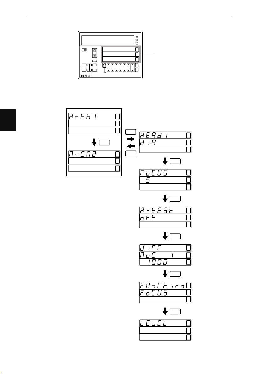
Chapter 4 Function Settings
Flow of Area Setting Display
AREA
1
2
FUNC
OUT 1
OUT 2
HI
GO
LO
AREA DISP
LS-7000
TIM
HI
GO
LO
HOLD
ZERO
This part changes.
POSITION
FOCUS
ESCPROG
PRINT
ENT
PROG No.
4
Area Setting
FUNC
HI
GO
PRINT
LO
ENT
ESC
HI
GO
LO
FUNC
Area Setting
HI
(See page 4-9)
GO
LO
Focus Monitor
HI
(See page 4-14)
GO
LO
FUNC
Area Check
HI
(See page 4-15)
GO
LO
FUNC
Difference
HI
Check
GO
(See page 4-16)
LO
FUNC
Function
HI
Output
GO
Selection
LO
(See page 4-17)
4-8
FUNC
Change of
HI
Edge Detection
GO
Threshold
LO
(See page 4-18)
Page 61

Chapter 4 Function Settings
Area Selection
Area
When a target is located in the measuring area as shown below, the light into the
receiver is partly obstructed, thus creating a shadow.
The contour of the shadow is called “edge.” The area is surrounded by the edge line.
The LS-7000 Series can measure objects with area designation or edge designation.
Area designation is possible in DIA, T-EDGE, or B-EDGE mode. Edge designation is
possible in SEG mode.
EDGE
AREA
Target
Transmitter Receiver
■ DIA (Diameter)
When the LS-7000 Series is in DIA measurement operation, it measures the outer
diameters of round bars or transparent
objects. The area between the top of the
first shadow and the bottom of the last
shadow is measured as shown in the
illustrations.
AREA
AREA
EDGE
EDGE
EDGE
4
Target
Transmitter
Target
Transmitter Receiver
Receiver
This space is
measured.
This space is
measured.
4-9
Page 62

Chapter 4 Function Settings
■ T-EDGE (Top Edge)/B-EDGE (Bottom Edge)
Select either of these settings for the gap
measurement or positioning of rollers.
4
When the LS-7000 Series is in T-EDGE measurement operation, it measures the width of
the bright portion between the top of the measuring head and the first shadow in the
measuring area.
When the LS-7000 Series is in B-EDGE measurement operation, it measures the width of
the bright portion between the bottom of the measuring area and the bottom of the last
object in the beam.
This space is measured in
T-EDGE mode or B-EDGE
mode.
This space is measured in
T-EDGE mode.
This space is measured in
B-EDGE mode.
Tips
Target
Transmitter
Target
Transmitter
Receiver
Receiver
Setting the reference edge within the measuring area enables measurements
in higher repeat accuracy.
■ SEG (Segment)
Select this setting for the measurement of the inner diameters of discs or the measurement of pitches.
The edge where the measurement of the object in the measuring area starts is called
“start edge” and the edge where the measurement terminates is called “end edge.” The
space between these edges specified is measured.
Segment measurement is performed in E mode or P mode. If objects are measured
with the virtual center of the light axis set, use edge 0.
Setting Range
• Edge or pitch numbers can be designated between –127 and 127.
• The duplicated designation of an edge or pitch number will set the measured value to
0.
• If edges or pitches are designated in reverse order, negative measured values will be
obtained.
4-10
Page 63

E (Edge) Mode
The LS-7000 Series measures objects
based on the edges in this mode.
Chapter 4 Function Settings
Set the edge numbers to positive values beginning with the top of the measuring head.
The following example shows positive edge numbers and measuring portions.
Top
Outer diameter 1
Clearance
Outer diameter 2
1E
2E
3E
4E
5E
6E
Bottom
Outer diameter 1: Space between 2E and 3E
(+2E to +3E)
Outer diameter 2: Space between 4E and 5E
(+4E to +5E)
Clearance: Space between 3E and 4E
(+3E to +4E)
Set the edge numbers to negative values beginning with the bottom of the measuring
head. The following example shows negative edge numbers and measuring portions.
Top
Outer diameter 1: Space between –5E and –4E
(–5E to –4E)
Outer diameter 2: Space between –3E and –2E
(–3E to –2E)
Clearance: Space between –4E and –3E
(–4E to –3E)
Outer diameter 1
Clearance
Outer diameter 2
-6E
-5E
-4E
-3E
-2E
-1E
Bottom
4
4-11
Page 64

Chapter 4 Function Settings
LO
P (Pitch) Mode
The LS-7000 Series measures objects
based on the middle point between the
edges of the objects in this mode.
In this example as shown, five P-mode
edges exist, based on which the LS-7000
measures the center pitch of the target in
the measuring area.
Center pitch: The space between 2P and
4P
4
Top
1E
1P
2E
2P
Target center pitch
3E
4E
5E
6E
Bottom
3P
4P
5P
Edge 0
Edge 0 refers to a method of measurement, in which the center of the optical
axis is used as an origin. In this case,
set the edge number to 0.
Use this method to position the objects or measure the movement or deviation of
objects.
Top
Edge position of workpiece
: Space between+1E and 0
(+1E to 0E)
In the edge 0 method, the E and
P modes will not make any difference.
Tips
Center of
optical axis
35.5 ± 0.2
1E
Edge 0
2E
Bottom
Use edge 0 method if higher repetitive accuracy is required from the measurement of objects.
■ Setting Procedure
1 Select the area to be set and press the
ENT
key.
4-12
2 Press the or key and select
the measuring method.
Set the following items that appear on the
HI
GO
LO
Page 65

screen.
H
Z
HI
Measuring head No. 1
HI
Measuring head No. 2
Chapter 4 Function Settings
POSITION
AREA
1
2
FOCUS
ESCPROG
PRINT
FUNC
ENT
PROG No.
HI
DIA (Diameter)
HI
T-EDGE (Top edge)
HI
B-EDGE (Bottom edge)
GO
SEG (Segment)
LO
AREA DISP
SEG (Segment) Setting
Input the start edge (pitch) number.
The value must be smaller than the end
edge (pitch number).
HI
Select the E or P
The setting part
flashes.
GO
mode as desired.
LO
Input the end edge
(pitch) number.
The value must be
larger than the start
edge (pitch) number.
Note: • The duplicated designation of an edge or pitch number will set the meas-
ured value to 0.
• If edges or pitches are designated in reverse order, negative measured
values will be obtained.
(1) Input the start edge (pitch) number.
LO
Press this key to set
the value to a positive
or negative one.
HOLD
ZERO
4
(2) Press the
ENT
key.
Select the E or P mode
Press these keys
with these keys.
to set the value.
4-13
Page 66

Chapter 4 Function Settings
H
Z
The input value is entered and the value in the next line flashes.
(3) Input the end edge (pitch) number.
4 Press the
ENT
key.
The input value is entered and the area display appears again.
Focus Monitor
The focus monitor is a function that makes it possible to check whether the target is located within the range where the highest precision measurement of the target is ensured.
The focus monitor range is the distance between the receiver and target in the measuring
area. When the target is within the range specified, the FOCUS indicator will light.
4
FOCUS display is lit
The center of the measuring area
Focus display is OFF
Setting Range
The value is set at 10 levels between 0 and 9. Set the value to 0 if the focus monitor
function is not used. Refer to Focus Characteristics on page 8-6 for the set values and
focus range in detail.
Tips
The result of focus monitoring can be externally output as function output.
Refer to Selection of Function Output on page 4-17 for details.
■ Setting Method
1 Select the area to be set and press
ENT
the
2 Press the
key.
FUNC
key.
HI
GO
LO
4-14
3 Press the or key and set the
value.
4 Press the
set.
The input value is entered and the area
display appears again.
key after the value is
ENT
POSITION
AREA
1
2
FOCUS
ESCPROG
PRINT
FUNC
ENT
PROG No.
AREA DISP
Page 67

Chapter 4 Function Settings
H
Z
Area Check
Set the total number of edges to be measured. If the number of edges detected does not
coincide with the set value, the measured value will be invalidated.
This function makes it possible to prevent the measurement of abnormal values that may
result if dust or oil is stuck on the measuring head.
The monitor will display the following data if the
measured value is invalidated.
POSITION
AREA
1
2
FOCUS
Setting Range
The setting range is between 2 and 127. Set the value to OFF if no area check is made.
OUT
OUT
HI
GO
LO
TIM
HI
GO
LO
Tips
The result of area checking can be external output as function output. Refer to
Selection of Function Output on page 4-17 for details.
■ Setting Method
1 Select the area to be set and press
ENT
the
2 Press the
key.
key twice.
FUNC
3 Press the or key and make
ON/OFF settings.
ON Setting
(1) Input the number of edges to be measured.
The setting part
flashes.
Press these keys
to set the value.
4
HI
GO
LO
POSITION
AREA
1
2
FOCUS
ESCPROG
PRINT
FUNC
ENT
PROG No.
AREA DISP
LO
HOLD
ZERO
4 Press the
ENT
key after the value is set.
The input value is entered and the area display appears again.
4-15
Page 68

Chapter 4 Function Settings
E
G
L
E
2
G
L
Difference Check
If there is a radical change between measured values, the change will be detected and
output.
Setting Range
• Difference average: 1 to 16 times
• Difference value: 1 to 9999 μm
4
Note: The results of difference checks will be output externally, provided that DIFF
function output settings are made properly in advance. Refer to Function
Output Selection on page 4-19 for details.
The result output of a difference check is a 26.6-ms-long single output signal,
which is not displayed on the control panel.
■ Setting Method
1 Select the area to be set and press
ENT
the
2 Press the
key.
FUNC
key three times.
3 Press the or key and set the averaging number.
POSITION
AREA
1
Averaging times
4 Press the
ENT
key.
2
FOCUS
ESCPROG
PRINT
FUNC
ENT
PROG No.
AREA DISP
H
Z
The setting
part flashes.
Press these
keys to set
the value.
The input value is entered and the difference value display flashes.
5 Press the or key and set the difference value.
HI
GO
LO
The setting
part flashes.
FOCUS
ESCPROG
PRINT
FUNC
ENT
PROG No.
Press these keys
to set the value.
AREA DISP
H
Z
Difference
value
4-16
Page 69

Chapter 4 Function Settings
H
Z
6 Press the
ENT
key after the value is set.
The input value is entered and the area display appears again.
Function Output Selection
Select either Focus, Area, or Difference to be output from the output terminal block on the
rear panel.
Setting Range
Any one of the following items is selectable for output. Refer to Section 6 I/O Terminals
on page 6-1 for the FUNCTION output terminals in details.
• Focus monitor
• Area check
• Difference check
■ Setting Method
1 Select the area to be set and press
ENT
the
2 Press the
key.
FUNC
key four times.
3 Press the or key and set the output item.
POSITION
AREA
1
2
Selected item
FOCUS
ESCPROG
PRINT
FUNC
ENT
PROG No.
AREA DISP
4
HI
GO
LO
The following items are displayed for
setting.
HI
Focus monitor
HI
Area check
HI
Difference check
4 Press the
ENT
key.
The input value is entered and the area
display appears again.
4-17
Page 70

4
Chapter 4 Function Settings
Change of Edge Detection Threshold
The following section provides information on how to make threshold changes for the
measurement of highly transparent objects.
Transparent
tape
Optical
reception
Brighter
Measuring range
Light blocked
by tape
Optical reception
Brighter
Threshold
(50%)
Threshold
(80%)
Darker
Detection impossible
50% threshold
When measuring a highly transparent
target, such as a plastic tape, the
amount of light blocked by the tape is
minimal. Therefore, the tape may not be
detected if the threshold is low.
Darker
Position Position
In that case, increase the threshold level
so that the tape will be detected
Detection
possible
80% threshold
Setting Range
The threshold can be set between 10% and 99% in 1% increments.
Note: • Only a single threshold can be set for each measuring head.
• In the measurement using the window edge such as T-EDGE or B-EDGE,
the measurement may become unstable with a higher threshold. In such a
case, use the reference edge or edge 0.
■ Optical Reception Waveform Output
While making a threshold setting for the target in the measuring area, an oscilloscope
can be used to output the optical reception waveform of the target so that the threshold
can be adjusted while monitoring the waveform.
10V
Approx. 6.5 V
0V
Approx.
10 ms
Trigger pulse
Optical reception waveform
(OUT1 analog output on terminal 22)
Threshold level
(OUT2 analog output on terminal 23)
4-18
Approx. 450 ms
Page 71

■ Setting method
E
G
L
Chapter 4 Function Settings
1 Select the area to be set and press
ENT
the
2 Press the
key.
FUNC
key five times.
3 Press the or key and set the threshold.
POSITION
AREA
1
2
Threshold
FOCUS
ESCPROG
PRINT
FUNC
ENT
4 Press the
ENT
key.
The input value is entered and the area display appears again.
PROG No.
Press these keys
to set the value.
AREA DISP
The setting part
flashes.
H
Z
HI
GO
LO
4
4-19
Page 72
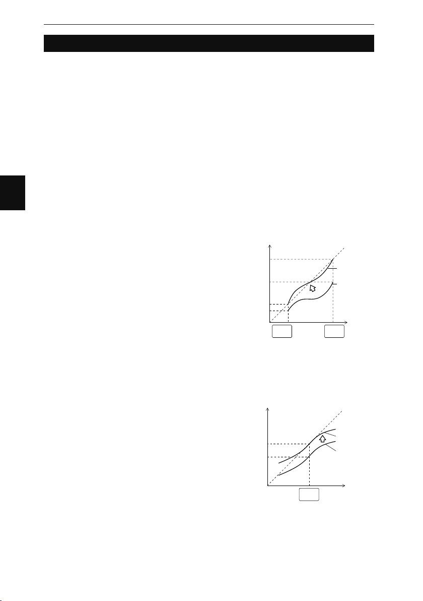
4
Chapter 4 Function Settings
Calibration Settings
The measured value of a target may have a subtle error due to the surface condition and
angle of the target. Calibration settings correct for this error. It is possible to make calibration settings for each area independently.
■ Types of Calibration Settings
Select the type of calibration from the following ones in advance. Refer to Calibration
Type Selection on page 4-23.
Logic calibration: Logic calibration requires two types of master workpieces that are
different to each other in size. Calibration is performed according
to pre-calibration and post-calibration values that are input by the
user. This type of calibration is used for the measurement of the
distance between two workpieces, for example.
Two-point calibration: Two-point calibration requires two types of master workpieces that
are different to each other in size.
One-point calibration: One-point calibration requires a single master workpiece. This
calibration is used for the size measurement of a single type of
workpiece.
Logic Calibration/Two-point Calibration
Prepare target 1 (T1) and target 2 (T2) as
two measuring points. The LS-7000 Series
performs calibration on these points based
on the T1-A and T2-A display values, which
are obtained before calibration, and the T2B and T2-B display values, which are
obtained after calibration. In this case, the
non-calibrated display values are converted
into the calibrated display values with the
span value (inclination) and shift value of
the workpiece determined by the LS-7000
Series internally.
One-point Calibration
Prepare target 1 (T1) as a single measuring
point. The LS-7000 Series performs calibration on this point based on the display value
before calibration and that after calibration.
In this case, the non-calibrated display
value is converted into the calibrated display
value with the span (inclination) and shift
value of the workpiece determined by the
LS-7000 Series internally. The span value is
always set to 1.
Display value
T2-B
(T2 after calibration)
(T2 before calibration)
(T1 after calibration)
(T1 before calibration)
(T1 after calibration)
(T1 before calibration)
T2-A
T1-B
T1-A
Display value
T1-B
T1-A
T1
(1st point)
T1
(1st point)
Display value
after calibration
Display value
before calibration
T2
(2nd point)
Display value
after calibration
Display value
before calibration
Ideal straight
line
Workpiece
size
Ideal straight
line
Workpiece
size
4-20
Page 73

■ Procedure for Calibration Settings
Make calibration settings while monitoring the sub display.
Chapter 4 Function Settings
1 Press the
2 Press the
key.
PROG
key four times.
FUNC
The “Calib” display appears.
FUNC
ESCPROG
PRINT
ENT
HI
GO
LO
4
4-21
Page 74

Chapter 4 Function Settings
Flow of Calibration Setting Display
POSITION
AREA
1
2
FOCUS
ESCPROG
PRINT
FUNC
ENT
OUT 1
OUT 2
HI
GO
LO
TIM
HI
GO
This part changes.
LO
HOLD
PROG No.
AREA DISP
ZERO
LS-7000
4
Calibration settings
ENT
HI
GO
LO
ESC
AREA 1 Calibration
Logic calibration
2-point calibration
1-point calibration
or
HI
GO
LO
HI
GO
LO
HI
GO
LO
or
THEORY (See page 4-23)
2-TARGET (See page 4-25)
1-TARGET (See page 4-26)
Initialization of
Calibration
(See page 4-26)
HI
GO
LO
FUNC
AREA 2 Calibration
Logic calibration
2-point calibration
1-point calibration
HI
GO
LO
HI
GO
LO
HI
GO
LO
or
HI
GO
LO
or
4-22
FUNC
FUNC
HI
GO
LO
HI
GO
LO
Calibration Type Selection (See page 4-23)
Page 75

Chapter 4 Function Settings
E
G
L
Calibration Type Selection
The following section provides information on how to set the calibration type for each area.
1 Press the
setting.
2 Press the
Press the
AREA2 calibration type.
3 Press the or key and select
the AREA1 calibration type.
The following items are displayed for
setting.
4 Press the
key for calibration
ENT
key twice.
FUNC
key three times to set the
FUNC
LO
Logic calibration
LO
Two-point calibration
LO
One-point calibration
key.
ENT
AREA
1
2
FUNC
POSITION
FOCUS
ESCPROG
PRINT
ENT
PROG No.
HI
GO
LO
AREA DISP
The input item is entered and the calibration setting display appears again.
Logic Calibration Settings
Make logic calibration settings as explained below.
Setting Range
Logic calibration does not require master workpieces. Input the non-calibrated values and
calibrated values of two measuring points (target 1 and target 2). Logic calibration uses the
following values
T1-A: Target 1 display value before calibration
T1-B: Target 1 display value after calibration
T2-A: Target 2 display value before calibration
T2-B: Target 2 display value after calibration
4
H
Z
Make settings so that the following conditions will be satisfied.
T1-A < T2-A and T1-B < T2-B
Furthermore, set the calibration span between 0.5 and 2.0.
4-23
Page 76

Chapter 4 Function Settings
4
1 Press the
ENT
key for calibration
setting.
The AREA1 calibration display appears.
Press the
key to make AREA2
FUNC
settings.
2 Input T1-A Value.
Indicates that AREA1
is selected.
Press this key to set
the value to a
positive or negative
one.
3 Press the
ENT
key.
POSITION
A
FOCUS
ESCG
PRINT
C
ENT
PROG No.
AREA DISP
The input value is entered and the value in the next line flashes.
4 Input T1-B Value.
The input
part flashes.
Indicates that
the T1-A value
HI
is displayed.
GO
LO
HOLD
ZERO
Press these keys to set
the value.
The input part
flashes.
HI
GO
LO
HI
GO
LO
5 Press the
ENT
key.
6 Input T2-A Value.
7 Press the
The input value is entered and the value in the next line flashes.
ENT
key.
8 Input T2-B Value.
9 Press the
The input item is entered and the calibration setting display appears again.
Note: If the calibration conditions are not satisfied, “Error-1” will appear on the main
4-24
ENT
key.
display. Reset the error status by pressing the
the calibration settings again.
ENT
key or
key and make
ESC
Page 77

Chapter 4 Function Settings
Two-point Calibration Settings
Make two-point calibration settings as explained below.
Setting Range
Two-point calibration requires two types of master workpieces that are different to each
other in size. If the master workpieces are target 1 (T1) and target 2 (T2) respectively,
make settings so that the following conditions will be satisfied.
T1 < T2
Furthermore, set the calibration span between 0.5 and 2.0.
Note: In the case of two-point calibration, the number of averaging measurements is
fixed at 4,096 times.
1 Press the
setting.
The AREA1 calibration display appears.
ENT
key for calibration
HI
GO
LO
2 Set the master workpiece, monitor the measured value, and input the T1 value.
Indicates that
HI
GO
LO
the T1 value is
displayed.
Displays the
measured value.
The input part
flashes.
Indicates that AREA1 is selected.
Press this key to set the value
to a positive or negative one.
3 Press the
ENT
key.
POSITION
A
FOCUS
ESCG
PRINT
C
ENT
PROG No.
HOLD
ZERO
AREA DISP
Press these keys to set
the value.
4 Set the other master workpiece, monitor the measured value, and input the T2
value.
5 Press the
The input item is entered and the calibration setting display appears again.
Note: If the calibration conditions are not satisfied, “Error-1” will appear on the main
ENT
key.
display. Reset the error status by pressing the
the calibration settings again.
ENT
key or
key and make
ESC
4
4-25
Page 78

Chapter 4 Function Settings
One-point Calibration Settings
Make one-point calibration settings as explained below.
4
Note: In the case of one-point calibration, the number of averaging measurements is
fixed at 4,096 times.
1 Press the
setting.
The AREA1 calibration display appears.
ENT
key for calibration
HI
GO
LO
2 Set the master workpiece, monitor the measured value, and input the T1 value.
Indicates that AREA1 is selected.
Indicates that AREA1 is selected.
POSITION
Press this key to set the value
to a positive or negative one.
3 Press the
ENT
key.
A
FOCUS
ESCG
PRINT
C
ENT
PROG No.
HI
GO
LO
HOLD
ZERO
AREA DISP
Press these keys to set
the value.
The input item is entered and the calibration setting display appears again.
Note: If the calibration conditions are not satisfied, “Error-1” will appear on the main
display.
Reset the error status by pressing the
ENT
key or
ESC
calibration settings again.
Indicates that
the T1 value is
displayed.
Displays the
measured value
The input part
flashes.
key and make the
Initialization of Calibration
Take the following procedure to initialize the calibration values you are setting or you have
already set (i.e., to return the values to the ones set by default).
In this case, the span value is by default set to 1 and the shift value is by default set to 0.
Note: It is possible to initialize the calibration value of each area independently.
1 Press the
setting.
The AREA1 calibration display appears.
4-26
key for calibration
ENT
HI
GO
LO
Page 79

Initializing AREA1 Calibration Value
E
G
L
E
G
L
E
G
L
(1) Press the
or key.
“Reset” appears on the screen.
(2) Confirm the area to be initialized and
ENT
press the
key.
Initialization of AREA2 Calibration Value
(1) Press the
FUNC
key.
The AREA2 settings appear.
AREA
1
2
FUNC
Chapter 4 Function Settings
POSITION
AREA
1
2
FOCUS
ESCPROG
PRINT
FUNC
POSITION
FOCUS
ESCPROG
PRINT
ENT
ENT
PROG No.
PROG No.
AREA DISP
AREA DISP
H
Z
4
H
Z
(2) Press the
or key.
“Reset” appears on the screen.
(3) Confirm the area to be initialized
and press the
ENT
key.
POSITION
AREA
1
2
FOCUS
ESCPROG
PRINT
FUNC
ENT
PROG No.
AREA DISP
H
Z
4-27
Page 80

4
Chapter 4 Function Settings
Output Settings
Values measured in AREA1 and AREA2 can be processed in a variety of ways and output
as OUT1 and OUT2 signals. This section provides information on the details and methods
of output settings.
Possible Output Settings
The following output settings are possible.
• Area calculation: The measured values of two-area points specified by area settings are used for calculation
processing.
• Number of averaging measurements: Set the number of measuring times.
• Measuring mode: Measured values are output “as is” or processed as maximum and minimum timing output
values.
• Offset: An offset value is a desired value that can be
added to or subtracted from measured values.
• Analog output: Analog voltages are output according to the
measured values.
• Comparator output: Set the details of output that turns ON according to the judgment results of measured values.
Output Settings
Make output settings while monitoring the sub display.
4-28
1 Press the
2 Press the
PROG
FUNC
key.
key twice.
To make OUT2 settings, press the
key again.
FUNC
FUNC
ESCPROG
PRINT
ENT
HI
GO
LO
Page 81

Flow of Output Setting Display
POSITION
AREA
1
2
FOCUS
ESCPROG
PRINT
FUNC
ENT
PROG No.
AREA DISP
LS-7000
OUT 1
OUT 2
HI
GO
LO
TIM
HI
GO
LO
HOLD
ZERO
Chapter 4 Function Settings
This part changes.
Output Settings
FUNC
HI
HI
GO
LO
HI
GO
LO
ENT
ESC
Area Calculation (See page 4-30)
GO
LO
FUNC
HI
Number of Averaging Measurements
GO
(See page 4-31)
LO
FUNC
HI
Measuring Mode (See page 4-33)
GO
LO
4
FUNC
HI
OFFSET (See page 4-43)
GO
LO
FUNC
DEV
TOL
HI
GO
LO
Scaling
(See page 4-44)
HI
GO
LO
FUNC
HI
Analog Update Mode (See page 4-46)
GO
LO
FUNC
HI
Output Waiting Voltage (See page 4-47)
GO
LO
FUNC
HI
Strobe Output Time (See page 4-47)
GO
LO
FUNC
HI
Output Logic (See page 4-48)
GO
LO
FUNC
HI
OFF-delay Time (See page 4-49)
GO
LO
4-29
Page 82

Chapter 4 Function Settings
Area Calculation
The measured values from the two memory areas are used for calculation processing.
Setting Range
Select the coefficient from the following.
OFF (No coefficient will be multiplied and the value will be 0), 1.0, 0.5, -1.0, or -0.5
■ Examples of Area Calculation
By multiplying the measured values with the coefficient selected, automatic size calculation will be obtained. Set the coefficient as explained below to obtain the desired
output value.
No Calculation is Performed
4
A1
A2
Obtaining the Outer Diameter from Two
Measuring Heads
Set AREA1 for DIA of measuring head 1
and AREA2 for DIA in measuring head 2.
A1
A2
Obtaining the object width from Two
Measuring Heads
Set AREA1 for B-EDGE in measuring head
1 and AREA2 for B-EDGE in measuring
head 2.
A1
A2
1.0
OFF
0.5
0.5
–1.0
–1.0
■ Setting Method
1 Press the
setting is displayed.
ENT
key when the output
HI
GO
4-30
LO
Page 83
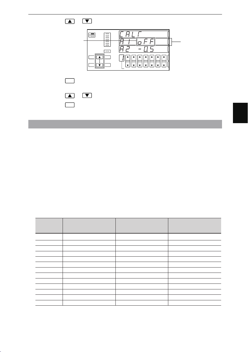
Chapter 4 Function Settings
E
G
L
2 Press the or key and set the coefficient for AREA1.
POSITION
AREA
1
The setting part flashes.
2
FOCUS
ESCPROG
PRINT
FUNC
ENT
PROG No.
AREA DISP
H
Z
AREA1 setting
3 Press the
ENT
key.
The input value is entered and the AREA2 value flashes.
4 Press the or key and set the coefficient for AREA2.
5 Press the
The input item is entered and the output setting display appears again.
Number of Averaging Measurements
Take the following procedure to determine the number of times to average measured
values.
Setting Range
Select the number of averaging measurements from the following.
1, 2, 4, 8, 16, 32, 64, 128, 256, 512, 1024, 2048, and 4096
If you want to average the fluctuation of measured values and obtain stable results,
select a comparatively large number. For high-speed measurement, the number selected should be comparatively small.
■ Averaging Time and Refresh Cycle
The LS-7000 Series averages measured values in a moving averaging method, thus
making it possible to output the measured values within a short time.
The following table lists the averaging time, the number of moving averaging data items,
and the refresh cycle of a target according to the number of averaging measurements.
Number of
averaging
measurements
1 0.42 1 0.42
2 0.83 2 0.83
4 1.67 2 0.83
8 3.33 2 0.83
16 6.67 2 0.83
32 13.33 2 0.83
64 26.67 2 0.83
128 53.33 2 0.83
256 106.67 4 1.67
512 213.33 8 3.33
1024 426.67 16 6.67
2048 853.33 32 13.33
4096 1706.67 64 26.67
key.
ENT
Averaging time (ms)
Number of moving
data samples
Refresh cycle (ms)
4
❈Measurement averaging time does not indicate the measuring response time of the
LS-7000 Series. Refer to Measuring Response Time on page 8-6 for details.
4-31
Page 84

Chapter 4 Function Settings
E
G
L
4
Example: If the averaging number is eight, the LS-7000 Series will output the data as
shown below.
Internal data
(2,400 samples/s)
Output data
1
2 3 4 5 6 7 8 9
Measurement averaging time
Measurement averaging time
Measurement averaging time
10 11 12 13 14
ABC
Refresh
Refresh
cycle
cycle
Data samples 1 through 8 are
averaged, and data A is output.
Data samples 3 through 10 are
averaged, and data B is output.
Data samples 5 through 12 are
averaged, and data C is output.
■ Setting Method
1 Press the
setting is displayed.
2 Press the
3 Press the or key and set the
averaging number.
key when the output
ENT
key.
FUNC
Averaging times
AREA
1
2
FUNC
POSITION
FOCUS
ESCPROG
PRINT
ENT
PROG No.
AREA DISP
HI
GO
LO
H
Z
4-32
4 Press the
ENT
key.
The input item is entered and the output setting display appears again.
Note:
When the measurement mode is set to Average Hold, set the averaging
number to 1.
Page 85

Chapter 4 Function Settings
Measuring mode
The Measuring mode allows the LS-7000 Series to capture and hold measured values.
Setting Range
The LS-7000 Series has 11 types of Measuring modes. Refer to the following information for the outline of each mode.
Normal
The measured
value is displayed
and output as it
occurs.
Bottom Hold
The minimum
value during the
period specified
is displayed and
output.
Average Hold
The average
value during the
period specified
is displayed and
output.
Auto Bottom Hold
The minimum
value measured
in displayed and
output as it
occurs.
Sample Hold 1
The instantaneous
value at the time
specified is
displayed and
output.
Synchronous input
(timing input)
Measured
value
Sampling time
Measured value
Sampling time
Minimum value
Minimum value
Average
value
Sample Hold 1
value
Peak Hold
The maximum
value during the
period specified
is displayed and
output.
Peak-to-peak Hold
The maximum-tominimum value
during the period
specified is
displayed and
output.
Auto Peak Hold
The maximum
value measured
is displayed and
output as it
occurs.
Auto Peak-to-peak Hold
The maximum-tominimum value
measured is
displayed and
output as it occurs.
Sample Hold 2
The value
measured during
the period specified
is displayed and
output.
Synchronous input
(timing input)
Max. value
Measured value
Sampling time
Measured value
Sampling time
Sampling time
Maximum-tominimum value
Max. value
Maximum-tominimum value
Sample hold 2
value
4
Self-timing Hold
The measured value is displayed and
output with no external timing input (i.e.,
timing input). The self-timing period is
adjustable between 1 and 9,999 ms.
ST
time
Workpiece insertion
Self-timing value
Sampling time
4-33
Page 86

Chapter 4 Function Settings
Application Example of Measuring modes
Select the measurement mode according to the type of target and measuring condition.
The following applications are typical examples of measurement in a variety of Measuring modes.
Application Applicable RUN mode
4
Continuous measurement of
wire, tube, or fiber
Measurement of maximum
value within specified period
Measurement of minimum
value within specified period
Measurement of maximum-tominimum value within specified
period
Measurement of average
values within specified period
Measurement of maximum
value per rotation
Measurement of minimum
value per rotation
Measurement of maximum-tominimum fluctuation or
eccentricity per rotation
Measurement of average value
per rotation
Single workpiece
measurement
Normal
Peak Hold
Auto Peak Hold
Bottom Hold
Auto Bottom Hold
Peak-to-peak Hold
Auto Peak-to-peak Hold
Average Hold
Peak Hold
Auto Peak Hold
Bottom Hold
Auto Bottom Hold
Peak-to-peak Hold
Auto Peak-to-peak Hold
Average Hold
Sample Hold 1
Sample Hold 2
Self-timing Hold
4-34
Page 87

Chapter 4 Function Settings
Timing Chart
The following table lists timing charts for respective measuring modes.
RUN mode Timing chart name Reference page
Normal
Peak Hold/Bottom Hold/
Peak-to-peak Hold/Average Hold
Auto Peak Hold/Auto Bottom Hold/
Auto Peak-to-peak Hold
Sample Hold 1
Sample Hold 2
Self-timing Hold
Normal
Peak Hold
Auto Peak Hold
Sample Hold 1
Sample Hold 2
Self-timing Hold
4-35
4-36
4-37
4-38
4-39
4-40
■ Normal
The value is continuously measured, displayed, and output in normal mode.
Measured value
Waiting for judgment
(---------- displayed)
HI set value
LO set value
HI output
GO output
LO output
Judgment awaiting output
(Comparator waiting output)
Timing input
RESET input
RS-232C output
• In addition to the above output signals, HH output and LL output are available though they are omitted from
the above chart.
• In the above chart, the ON status of each output means that NPN open collector output is ON, provided
that it is normally open type. If it is normally closed type, the signal will be inverted.
• The ON status of each input means that the input is short-circuited to the COM terminal.
• RS-232C output is ON in synchronization with timing input if the D-SEND item as an environment setting is
set to S1 or S2 only. Refer to Data Transmission Mode on page 5-9 for environment settings in detail.
• For strobe output in detail, refer to Strobe Output Time on page 4-48.
• For BCD output in detail, refer to BCD Output on pages 6-9 and 6-13.
OFF
OFF
OFF
OFF
OFF
OFF
OFF
ON
ON
ON
ON
ON
ON
ON
Measured value in normal mode
Internal measured value
Measured value
RESET processing
4
t
Tips
• If RESET input is ON while timing input is ON, awaiting the result of measurement, the monitor will display the result waiting status “---.-----” until the
timing input is turned OFF.
• Comparator waiting output can be OFF-delayed. Refer to OFF-delay Time
on page 4-49 for the details of OFF-delays.
• Timing input and reset input can be sent by RS-232C control. Refer to page
7-8 for details.
4-35
Page 88

Chapter 4 Function Settings
■ Peak Hold
• Peak hold: The maximum value during the sampling period specified by
• Bottom hold: The minimum value during the sampling period specified is
• Peak-to-peak hold: The maximum-to-minimum value during the period specified is
• Average hold: The average value during the sampling period specified is dis-
external timing input is displayed and output as shown below.
displayed and output.
displayed and output.
played and output.
4
Measured value
Waiting for judgment
(---------- displayed)
Internal
measured value
Sampling
period
Timing input
RESET input
Comparator output
Judgment awaiting output
(Comparator waiting output)
Strobe output
BCD output
RS-232C output
• Timing input is OFF during sampling periods. The maximum value during the sampling period immediately
before timing input will be output when the timing input turns ON.
• In the following cases, the monitor will display the result waiting status “---.-----” until the first measured
value is determined.
The LS-7000 is turned on, setting changes are made, program number changes are made, RESET
input is ON, or auto zero is input.
• Comparator output turns ON according to the measured value.
• In the above chart, the ON status of each output means that NPN open collector output is ON, provided
that it is normally open type. If it is normally closed type, the signal will be inverted.
• The ON status of each input means that the input is short-circuited to the COM terminal.
• RS-232C output turns ON in synchronization with timing input if the D-SEND item as an environment
setting is set to S1 or S2 only. Refer to Data Transmission Mode on page 5-9 for environment settings in
detail.
• If timing input is ON during reset processing, the monitor will display the result waiting status
“---.-----.”
OFF
OFF
OFF
OFF
OFF
ON
ON
ON
ON
ON
Sampling period
Judgment
Measured value Measured value Measured value
Peak hold measured value
processing
Judgment
Measured valueMeasured value
RESET
Sampling period
t
Judgment
Measured value
4-36
Tips
Note:
• If a workpiece is eliminated during a sampling period and it becomes a
period without the internal measured value obtained, the maximum value of
the rest of the normal measured values will be output.
• Timing input and RESET input can be under RS-232C control. Refer to
page 7-8 for details.
• Strobe output time can be changed. Refer to Strobe Output Time on page 448 for details.
When the measurement mode is set to Average Hold, set the averaging
number to 1.
Page 89

Chapter 4 Function Settings
■ Auto Peak Hold
• Auto peak hold: The maximum value measured by the LS-7000 Series in
• Auto bottom hold: The minimum value measured by the LS-7000 Series in
• Auto peak-to-peak hold: The maximum-to-minimum value measured by the LS-7000
Waiting for judgment
(---------- displayed)
continuous measurement operation is displayed and output.
continuous measurement operation is displayed and output.
Series in continuous measurement operation is displayed
and output .
Measured value
Auto peak hold measured value
Internal
measured value
RESET
processing
JudgmentJudgment
Measured value
Timing input
RESET input
Comparator output
Judgment awaiting output
(Comparator waiting output)
• Comparator output turns ON according to the measured value.
• In the above chart, the ON status of each output means that NPN open collector output is ON, provided
• The ON status of each input means that the input is short-circuited to the COM terminal.
• RS-232C output is ON in synchronization with timing input if the D-SEND item as an environment setting is
• For strobe output in detail, refer to Strobe Output Time on page 4-48.
• For BCD output in detail, refer to BCD Output on pages 6-9 and 6-13.
• If timing input is ON during reset processing, the monitor will display the result waiting status “---.-----.”
Tips
RS-232C output
that it is normally open type. If it is normally closed type, the signal will be inverted.
set to S1 or S2 only. Refer to Data Transmission Mode on page 5-9 for environment settings in detail.
• If RESET input is ON while timing input is ON, awaiting the result of meas-
OFF
OFF
OFF
OFF
ON
ON
ON
ON
urement, the monitor will display the result waiting status “---.-----” until the
timing input is turned OFF.
• Timing input and reset input can be under RS-232C control. Refer to page
7-8 for details.
• If a workpiece is missing and there is a period without the internal measured
value obtained, the monitor will display the result waiting status “---.-----.” The
LS-7000 Series will start measurement with the previous auto peak value
maintained when the internal measured value is obtained.
4
t
4-37
Page 90
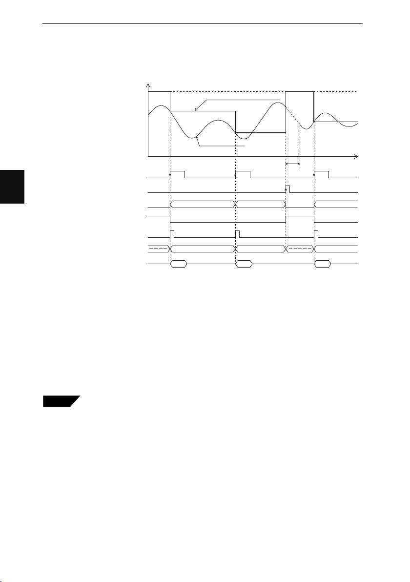
4
Chapter 4 Function Settings
■ Sample Hold 1
The instantaneous value at the time specified by external timing input is displayed, and
the value is output as shown below.
Measured value
Waiting for judgment
(---------- displayed)
Timing input
RESET input
Comparator output
Judgment awaiting output
(Comparator waiting output)
• When timing input turns ON, the internal measured value will be held. Then the value will be output.
• In the following cases, the monitor will display the result waiting status “---.-----” until the first measured
value is determined.
• Comparator output turns ON according to the measured value.
• In the above chart, the ON status of each output means that NPN open collector output is ON, provided
that it is normally open type. If it is normally closed type, the signal will be inverted.
• The ON status of each input means that the input is short-circuited to the COM terminal.
• RS-232C output is ON in synchronization with timing input if the D-SEND item as an environment setting is
set to S1 or S2 only. Refer to Data Transmission Mode on page 5-9 for environment settings in detail.
• If timing input is ON during reset processing, the monitor will display the result waiting status
“---.-----.”
Strobe output
BCD output
RS-232C output
The LS-7000 is turned on, setting changes are made, program number changes are made, RESET
input is ON, or auto zero is input.
OFF
OFF
OFF
OFF
OFF
ON
ON
ON
ON
ON
Measured value Measured value Measured value
Sample hold measured value
Internal
measured value
Judgment
RESET
processing
Judgment Judgment
Measured valueMeasured valueMeasured value
t
4-38
Tips
• Timing input and RESET input can be under RS-232C control. Refer to
page 7-8 for details.
• Strobe output time can be changed. Refer to Strobe Output Time on page 448 for details.
Page 91

Chapter 4 Function Settings
■ Sample Hold 2
The value measured during the period specified by external timing input is displayed,
and the value is output as shown below.
Measured value
Waiting for judgment
(---------- displayed)
Internal measured value
Sample hold measured value
Judgment
Measured value
Sampling
period
Judgment
Measured value
RESET
time
Sampling
period
Judgment
Measured value
Timing input
RESET input
Comparator output
Judgment awaiting output
(Comparator waiting output)
Strobe output
BCD output
RS-232C output
OFF
OFF
OFF
OFF
OFF
Sampling
ON
ON
ON
ON
ON
period
Measured value Measured value Measured value
• When timing input is ON, input data is sampled for the averaging number. The determined internal
measured value will be held. Then the value will be output.
• In the following cases, the monitor will display the result waiting status “---.-----” until the first measured
value is determined.
The LS-7000 is turned on, setting changes are made, program number changes are made, RESET
input is ON, or auto zero is input.
• Comparator output turns ON according to the measured value.
• In the above chart, the ON status of each output means that NPN open collector output is ON, provided
that it is normally open type. If it is normally closed type, the signal will be inverted.
• The ON status of each input means that the input is short-circuited to the COM terminal.
• RS-232C output is ON in synchronization with timing input if the D-SEND item as an environment setting is
set to S1 or S2 only. Refer to Data Transmission Mode on page 5-9 for environment settings in detail.
• If timing input turns ON while the LS-7000 Series is in process of resetting, the process of resetting will be
interrupted and sampling will start.
• If the internal measured value during a sampling period becomes “---.-----,” the monitor will display the
result waiting status “---.-----.”
Tips
• Timing input and RESET input can be under RS-232C control. Refer to
page 7-8 for details.
• Strobe output time can be changed. Refer to Strobe Output Time on page 448 for details.
t
4
4-39
Page 92
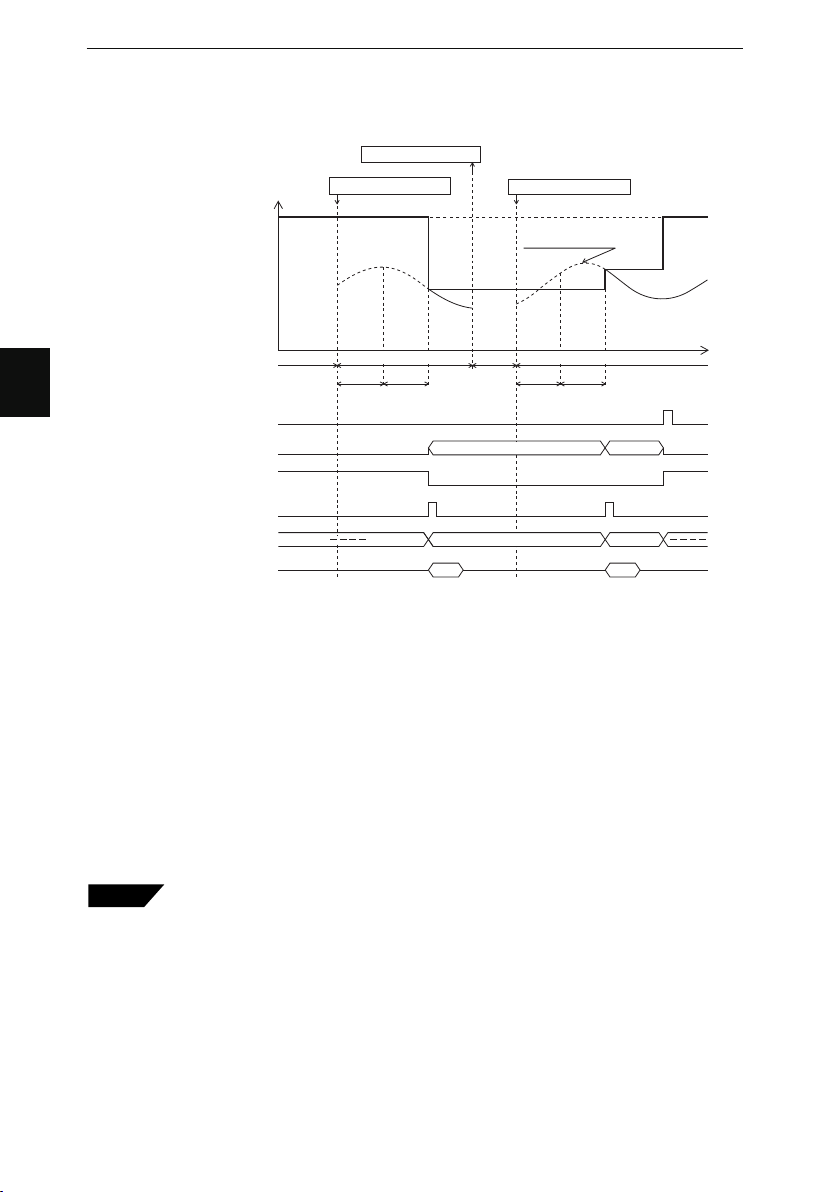
Chapter 4 Function Settings
■ Self-timing Hold
The LS-7000 Series in self-timing hold operation will detect targets automatically with
no external timing input. Then the measured value is displayed and output.
Warkpiece removed
Measured value
Waiting for judgment
(---------- displayed)
Workpiece insertion
Workpiece insertion
Internal
measured value
4
RESET input
Comparator output
Judgment awaiting output
(Comparator waiting output)
Strobe output
BCD output
RS-232C output
OFF
OFF
OFF
OFF
ON
ON
ON
ON
No internal
measured value
Internal measured value Internal measured value
Sampling
ST
period
time
No internal
measured value
Judgment
Measured value
Measured value Measured value
time
Sampling
ST
period
Judgment
Measured value
• When a workpiece is within the sensing distance, the emergence of the internal measured value will be
used as a trigger. Then data will be sampled for the averaging number after the preset self-timing (ST)
period is over. The determined internal measured value will be held. Then the value will be output.
• In the following cases, the monitor will display the result waiting status “---.-----” until the first measured
value is determined.
The LS-7000 is turned on, setting changes are made, program number changes are made, RESET
input is ON, or auto zero is input.
• Comparator output turns ON according to the measured value.
• In the above chart, the ON status of each output means that NPN open collector output is ON, provided
that it is normally open type. If it is normally closed type, the signal will be inverted.
• The ON status of each input means that the input is short-circuited to the COM terminal.
• RS-232C output is ON in synchronization with timing input if the D-SEND item as an environment setting is
set to S1 or S2 only. Refer to Data Transmission Mode on page 5-9 for environment settings in detail.
• Timing input is ignored.
• If the internal measured value during a sampling period becomes “---.-----,” the monitor will display the
result waiting status “---.-----.”
Tips
• RESET input can be under RS-232C control. Refer to page 7-8 for details.
• Strobe output time can be changed. Refer to Strobe Output Time on page 448 for details.
• The monitor will display “TIM” until the next workpiece is located in the
measuring area after the present measured value is determined.
t
4-40
Page 93

Chapter 4 Function Settings
● Self-timing Hold and Area Settings
The LS-7000 Series in self-timing hold operation will detect a target when the target is
within the optical axis. Then the LS-7000 Series will start sampling after a certain period
(i.e., a self-timing period) elapses. Therefore, the target may enter the measuring area
from any direction as shown below.
The LS-7000 Series will detect the target within the optical axis when the LS-7000
Series confirms a certain number of edges and not at the moment the target enters the
optical axis. The confirmation condition varies with the measurement method selected
as an area setting. Refer to the following examples.
Diameter (DIA) Measurement
The target will be detected when the number of edges in the optical axis is four or over.
Edge
1
2
Edge
1
2
3
4
4
The number of edges in the optical axis is
two. The target has not been detected yet.
The number of edges in the optical axis is
four or over. The target has been detected.
Segment (SEG) Measurement
The target will be detected when the number of edges in the optical axis coincides with
the number of edges specified.
In the following example, settings are made so that the width between edges 002 and
003 will be measured.
1
Edge
2
The specified edge value (003) has not
been detected within the optical axis. The
target has not been detected.
The specified edge value has been
detected within the optical axis. The
target has been detected.
Edge
1
2
3
4
Note: The LS-7000 Series in self-timing hold mode cannot be used for the following
measurement applications, when the LS-7000 Series will be always in measurement operation regardless of whether there is a target or not (because the
internal measured value always exists).
Example: • T-EDGE (Top edge) measurement
• B-EDGE (Bottom edge) measurement
• SEG (Segment) measurement of 001 and 002 edge widths
4-41
Page 94

Chapter 4 Function Settings
E
G
L
Setting Method
4
1 Press the
key when the output
ENT
setting is displayed.
2 Press the
key twice.
FUNC
3 Press the or key and set the
measuring mode.
The following displayed items can be selected.
GO
Normal
GO
Peak hold
GO
Bottom hold
GO
Peak to peak hold
GO
Average hold
GO
Auto peak hold
HI
GO
LO
POSITION
AREA
1
2
FOCUS
ESCPROG
PRINT
FUNC
ENT
PROG No.
GO
Auto bottom hold
GO
Auto peak to peak hold
GO
Sample hold 1
GO
Sample hold 2
GO
Self timing hold
LO
AREA DISP
H
Z
4-42
Self-timing Hold Setting
The possible setting range is from 1 to 9999 ms.
The selectable
part flashes.
(1) Press the or key and set the
self-timing period.
HI
GO
LO
POSITION
A
FOCUS
ESCG
PRINT
C
ENT
Self-timing period
detected
PROG No.
AREA DISP
HI
GO
LO
HOLD
ZERO
Press these keys
to set the value.
Page 95

Chapter 4 Function Settings
4 Press the
ENT
key.
The input item is entered and the output setting display appears again.
Offset
An offset value is a desired value that can be added to or subtracted from measured
values. If the offset value is set, it is possible to display the offset value immediately on the
screen by using the auto zero function.
Setting Range
The range can be set between –99.99999 and 99.99999 mm. This range varies with the
display unit or minimum display unit setting. Refer to Display Unit on page 4-57 and
Minimum Display Unit on page 4-58.
Input positive or negative values to increase or decrease the set value.
1 Press the
setting is displayed.
2 Press the
key when the output
ENT
key three times.
FUNC
HI
GO
LO
3 Press the or key and set the offset value.
POSITION
Press this key to set the value
to a positive or negative one.
A
FOCUS
ESCG
PRINT
C
ENT
PROG No.
AREA DISP
HI
GO
LO
HOLD
ZERO
The selectable
part flashes.
4
Press these keys
to set the value.
4 Press the
ENT
key.
The input item is entered and the output setting display appears again.
■ Master Calibration with Automatic Zero (Automatic Offset) Function
The automatic zero function sets measured values to the preset size values (i.e., offset
values) of master workpieces. Refer to Measurement of Outer Diameter and Width (with
Two Measuring Heads for Larger Objects) on page 2-4 for an application example. For
the details of the automatic zero function, refer to Automatic Zero Function on page 3-6.
4-43
Page 96

4
Chapter 4 Function Settings
Analog Output Settings
The LS-7000 Series has analog voltage output according to the measured value. The
range of analog voltage output is between –10 and +10 V.
Setting Range
The following analog output settings are available.
• Scaling (reference value): In reference value mode (LIMITS), the deviation is output
as a positive or negative voltage based on the reference
value of 0 V. Select the scaling of deviation from the following: 1, 2, 5, 10, 20, 50, 100, 200, 1000, 2000, 5000, and
10000 μm/V
• Scaling (threshold): In threshold mode, set the measurement values to be
output at +10 V and –10 V respectively so that the scaling
value will be decided.
The absolute value of the difference between these values
must satisfy the following condition.
{(Measured value at +10 V) – (Measured value at –10 V)}
X
Value X varies with the minimum display unit.
The relationship between value X and minimum display unit
is shown below.
>
=
0.2
2
Minimum display unit (μm)
0.01, 0.02, 0.05
0.1, 0.2
1
0.00001, 0.00002, 0.00005
0.0001, 0.0002
0.001, 0.01, 0.1
X(mm)
0.02
• Analog Update Mode The measured value after area calculation is output after
the analog scaling of the value regardless of whether the
display value is held or not. The function is ON/OFF
selectable.
• Output Waiting Voltage Set the output voltage of the LS-7000 Series when the
display shows “---.-----.” The items selectable are 0 V, 10.5
V, and HOLD (holding the previous voltage before the LS7000 Series began waiting for the result of the measurement).
■ Scaling
There is a difference in scaling settings between the LS-7000 Series in tolerance mode
with reference values used and that with thresholds used. Refer to Tolerance Mode
(LIMITS) on page 4-56 for details.
● Tolerance Mode with Reference Value
Based on a reference value of 0 V, the
deviation is output as positive or negative
voltage. The voltage can be changed while
the result waiting status is “---.-----.” (See
page 4-47)
(Positive value
over range)
(Negative value
below range)
Voltage
+10.5V
+10V
–10V
–10.5V
0V
Scaling is changeable
at 13 steps.
Measured value
Reference value set by
tolerance
X(μm)Minimum display unit (mm)
20
200
2000
4-44
Page 97

Chapter 4 Function Settings
The following table shows the relationship of scaling values along with their output
ranges and resolutions.
Scaling value [μm/V] Output range Resolution (❈)
1 ±10μm 0.01μm
2 ±20μm 0.01μm
5 ±50μm 0.02μm
10 ±100μm 0.04μm
20 ±200μm 0.08μm
50 ±500μm 0.2μm
100 ±1mm 0.4μm
200 ±2mm 0.8μm
500 ±5mm 2μm
1000 ±10mm 4μm
2000 ±20mm 8μm
5000 ±50mm 20μm
10000 ±100mm 40μm
❈If the minimum display unit selected is larger than the resolution selected, the mini-
mum display unit will be used as applicable resolution.
■ Setting Method
4
1 Press the
ENT
key when the output
setting is displayed.
2 Press the
FUNC
key four times.
3 Press the or key and set the scaling value.
4 Press the
The input item is entered and the output setting display appears again.
● Tolerance Mode with Threshold
Set the measurement values to be output at
10 V and –10 V respectively so that the
scaling value will be decided. The voltage
can be changed while the result waiting
status is “---.-----.” (See Page 4-47)
ENT
key.
(Positive value
over range)
(Negative value
below range)
Voltage
+10.5V
+10V
–10V
–10.5V
0V
030
+10V :30mm
0mm
–10V :
HI
GO
LO
Measured value
4-45
Page 98
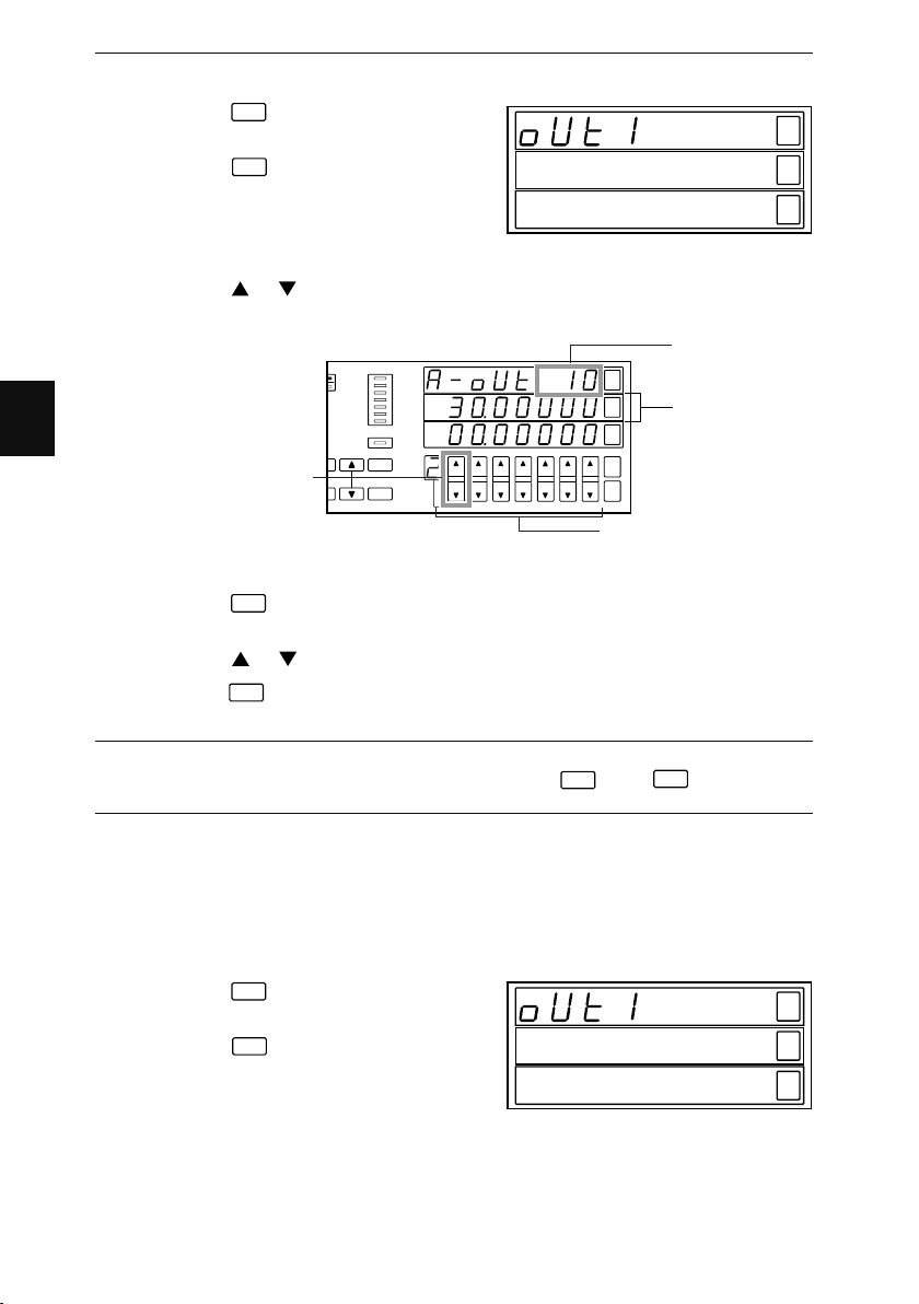
4
Chapter 4 Function Settings
Setting Method
1 Press the
ENT
key when the output
setting is displayed.
2 Press the
FUNC
key four times.
3 Press the or key and set the +10 V value.
POSITION
A
FOCUS
Press this key to a
positive or negative
one.
ESCG
PRINT
C
ENT
PROG No.
HI
GO
LO
HOLD
ZERO
AREA DISP
Press these keys to
set the value.
Indicates +10 V
value.
The selectable
part flashes.
HI
GO
LO
4 Press the
ENT
key.
The input item is entered and the value in the next line flashes.
5 Press the or key and set the -10 V value.
6 Press the
The input item is entered and the output setting display appears again.
Note: If the input conditions are not satisfied, “Error-4” will appear on the main
display. Reset the error status by pressing the
the settings again.
■ Analog update mode
If the analog update mode is ON, the measured value after area calculation will be
output after analog scaling.
1 Press the
setting is displayed.
2 Press the
key.
ENT
key when the output
ENT
key five times.
FUNC
ENT
key or
ESC
key and make
HI
GO
LO
4-46
Page 99

Chapter 4 Function Settings
E
G
L
E
G
L
POSITION
3 Press the or key and set the
analog update mode.
4 Press the
The input item is entered and the output
setting display appears again.
ENT
key.
AREA
1
2
FUNC
FOCUS
ESCPROG
PRINT
ENT
PROG No.
■ Output Waiting Voltage
Take the following steps to set the voltage to be output when the display shows
“- - - - - - - -.”
1 Press the
setting is displayed.
2 Press the
3 Press the or key and set the
voltage.
4 Press the
The input item is entered and the output
setting display appears again.
key when the output
ENT
key six times.
FUNC
key.
ENT
AREA
1
2
FUNC
POSITION
FOCUS
ESCPROG
PRINT
ENT
PROG No.
AREA DISP
AREA DISP
H
Z
HI
GO
LO
4
H
Z
Comparator Output Setting
Adjust the comparator output settings.
Setting Range
The following comparator output settings are available.
• Strobe output time: Select the ON-time of the strobe output (i.e., one-shot output
• Output logic: Set the logic of the comparator output and WAITING output to NO
• OFF-delay time: Select the OFF-delay time of the comparator output from 0.0, 0.4,
time) from 0.4, 0.8, 1.6, 3.3, 6.6, 13.3, and 26.6 ms.
(normally open) or NC (normally closed).
0.8, 1.6, 3.3, 6.6, 13.3 and 26.6 ms.
4-47
Page 100

Chapter 4 Function Settings
E
G
L
E
G
L
■ Strobe Output Time
Take the following steps to set the ON-time of strobe output.
4
1 Press the
ENT
key when the output
setting is displayed.
2 Press the
3 Press the or key and set the
output time.
4 Press the
The input item is entered and the output
setting display appears again.
FUNC
key seven times.
ENT
key.
POSITION
AREA
1
2
FOCUS
ESCPROG
PRINT
FUNC
ENT
PROG No.
■ Output Logic
The logic of comparator output and WAITING output can be set to NO (normally open)
or NC (normally closed).
1 Press the
setting is displayed.
2 Press the
3 Press the or key and set
the output logic.
The following displayed items can be
selected.
ENT
key when the output
FUNC
key eight times.
N.O.
GO
(Normally open)
N.C.
GO
(Normally closed)
POSITION
AREA
1
2
FOCUS
ESCPROG
PRINT
FUNC
ENT
PROG No.
AREA DISP
AREA DISP
HI
GO
LO
H
Z
HI
GO
LO
H
Z
4-48
4 Press the
ENT
key.
The input item is entered and the output setting display appears again.
 Loading...