

Page 1

Instruction
Manual
High-speed Laser Scan Micrometer
96M12426
LS-5000 Series
Page 2

Safety Precautions
WARNING
CAUTION
CAUTION
This instruction manual describes the operation and function of the LS-5000 series.
Read this manual carefully to ensure safe use and maximum performance from
your LS-5000 series.
The LS-5000 series uses a semiconductor laser as the light source. Before using
the product, see “Laser Safety Precautions” on page 1 to learn the safe and correct
method of using the LS-5000 series.
Symbols
The following symbols alert you to important messages. Be sure to read these
messages carefully.
Failure to follow instruction may lead to injury. (electric
shock, burn, etc.)
Failure to follow instructions may lead to product damage.
General Precautions
Note:
• At startup and during operation, be sure to monitor the functions and performance of the LS-5000 series.
• We recommend that you take substantial safety measures to avoid any damage
in the event a problem occurs.
• Do not open or modify the LS-5000 series or use it in any way other than
described in the specifications.
• When the LS-5000 series is used in combination with other instruments, functions and performance may be degraded, depending on operating conditions
and the surrounding environment.
• Do not use the LS-5000 series for the purpose of protecting the human body.
This is a class A (EN55011: EMI standard) product. In a domestic environment this
product may cause radio interference in which case the user may be required to
take adequate measures.
Provides additional information on proper operation.
i
Page 3

Checking the Contents of the Package
The LS-5000 series includes the following items. Be sure to check that no item is
missing or damaged.
■ LS-5501 Package
• Built-in display type controller: 1
• Instruction manual: 1
• AC power cables: 2
■ LS-5001 Package
• Separate type controller: 1
• Instruction manual: 1
• Communication cable (OP-26401 + OP-96368): 1
• LS-VIEWER Software (3.5-inch FD, Instruction manual): 1
■ LS-5041/5121 Package
• Scanning head (Transmitter, receiver and mounting base): 1
• Mounting brackets: 4
• ROM board: 1
1. Two types of AC power cables are provided with the built-in display model LS-5501. One is for 125
VAC and the other is for 250 VAC. Select either according to your local power supply type.
2. The serial nos. of both units should be identical.
1.
2.
2.
Warranty
Notice
See page 125.
• No part of this instruction manual may be reprinted or reproduced without the
prior written permission of KEYENCE CORPORATION.
• KEYENCE assumes no responsibility for the contents of this manual. No liability
is assumed for damages resulting from a program created by customers.
• The contents of this manual are subject to change without notice.
96M12426
ii
Page 4

Contents
Chapter 1 Laser Safety Precautions
Chapter 2 Before Using the LS-5000 Series
1.1 Classification .......................................................................................... 2
1.2 Warning Labels ...................................................................................... 2
1.3 Label Location ........................................................................................ 3
1.4 Safety Consideration .............................................................................3
1.5 Safety Features Provided with the LS-5000 Series ............................. 4
1.6 Preparation for Operation ..................................................................... 6
2.1 System Configuration and Connections ............................................. 8
2.1.1 System Configuration ................................................................................ 8
2.1.2 Connection Procedure .............................................................................. 9
2.2 Names and Functions of Indicators and Switches ...........................12
2.3 Part Names ........................................................................................... 13
Chapter 3 Quick Start Reference
3.1 Quick Start Reference ......................................................................... 16
3.1.1 Procedure for Starting Measurement ......................................................16
Chapter 4 Installation
4.1 Mounting the Scanning Head ............................................................. 18
4.2 Mounting the Controller ...................................................................... 19
Chapter 5 Outline of Measurements
5.1 Area/Segment/Edge .............................................................................22
5.2 Normal mode ........................................................................................22
5.2.1 DIA mode ................................................................................................ 23
5.2.2 T.EDGE (TOP EDGE) mode/B.EDGE (BOTTOM EDGE) mode ............ 23
5.2.3 SEG (m,n) mode ..................................................................................... 23
5.3 Pitch mode ............................................................................................ 24
iii
Page 5

Chapter 6 Normal mode
6.1 Normal Mode Screens ......................................................................... 24
6.2 Initial Screen ......................................................................................... 27
6.3 Setting Measuring Mode ..................................................................... 28
6.4 Setting Functions ................................................................................. 29
1 [HOLD] Hold Function...................................................................... 30
2 [ZERO] Auto-zero Function ............................................................. 31
3 [SCREEN] Screen Selection Function ............................................. 32
4 Limit Setup ....................................................................................... 35
5 [CALIB] Calibration Setup ................................................................ 36
6 [PROGRAM] Program Selection Function ....................................... 38
7 Area Setup ....................................................................................... 39
8 Calculation Setup ............................................................................. 41
9 Average ........................................................................................... 44
0 Measuring Mode ..............................................................................46
A Digit Suppression Function .............................................................. 54
B Offset Function ................................................................................ 55
C Analog Output Function ...................................................................57
D I/O Slot Setup .................................................................................. 59
E Inspection ........................................................................................ 60
F One-scan Mode ............................................................................... 62
G Program Selection Method Setup .................................................... 64
H Display Unit ...................................................................................... 65
I Area Check Function ....................................................................... 66
J Initialize ............................................................................................ 67
K Mode Change .................................................................................. 68
Chapter 7 Pitch Mode
7.1 Pitch Mode Screens ............................................................................. 70
7.2 Initial Screen ......................................................................................... 71
7.3 Setting Measurement ........................................................................... 72
7.4 Setting Functions ................................................................................. 72
1 Screen Selection Function ............................................................... 73
2 Limit Setup ....................................................................................... 75
3 Program Selection Function ............................................................76
4 Setting Number of Pitches ...............................................................77
5 Average ........................................................................................... 79
6 Digit Suppressing Function .............................................................. 80
7 Measuring Mode ..............................................................................81
8 Masking ...........................................................................................84
9 Mode Change .................................................................................. 85
iv
Page 6

Chapter 8 RS-232C I/O
8.1 RS-232C Communication Protocol .................................................... 88
8.2 Remote Control Function .................................................................... 90
8.3 Command List ......................................................................................97
Chapter 9 Expansion I/O Board
9.1 Control I/O Board ...............................................................................100
9.1.1 Part Names and Pin Assignment .......................................................... 100
9.1.2 I/O Terminal Operations ........................................................................ 101
9.1.3 Specifications ........................................................................................102
Chapter 10 Display System Setup
10.1 Display System Setup .....................................................................104
10.1.1 Adjusting Backlight Intensity ...............................................................104
10.1.2 Reversing Display ............................................................................... 105
10.1.3 Adjusting Contrast .............................................................................. 106
10.1.4 Setting Backlight OFF Time ................................................................ 107
10.1.5 Adjusting Buzzer Volume.................................................................... 108
10.1.6 Numeric Keys .....................................................................................109
10.2 Display Hardware Check Function ................................................. 110
10.3 Replacing Protective Sheet ............................................................. 111
10.4 Display Panel-lock Function ...........................................................112
Appendices
Appendix A Specifications ........................................................................114
Appendix B Initial Setting .......................................................................... 116
Appendix C Troubleshooting Guide ......................................................... 118
Appendix D Error Messages ...................................................................... 120
Appendix E Minimum Input Time and Output Response Time .............. 121
Appendix F Dimensions ............................................................................122
WARRANTIES AND DISLAIMERS 125
v
Page 7

Chapter 1
Laser Safety Precautions
1.1 Classification ........................................................................ 2
1.2 Warning Labels ..................................................................... 2
1.3 Label Location ...................................................................... 3
1.4 Safety Consideration ............................................................ 3
1.5 Safety Features Provided with the LS-5000 Series ........... 4
1.6 Preparation for Operation .................................................... 6
Page 8

Chapter 1 Laser Safety Precautions
CAUTION
1.1 Classification
1
1.2 Warning Labels
LS-5041 LS-5121
Laser FDA (CDRH) Part 1040.10 Class II Laser Product
Class IEC60825-1 Class 2 Laser Product
■ LS-5041
Warning label/Aperture label
FDA Class II IEC Class 2
IEC (French) Classe 2 DIN Klasse 2
■ LS-5121
Warning label/Aperture label
FDA Class II IEC Class 2
AVOID EXPOSURE
LASER RADIATION
IS EMITTED FROM
THIS APERTURE.
CAUTION
LASER RADIATIONDO NOT STARE INTO BEAM
SEMICONDUCTOR LASER
WAVELENGTH
OUTPUT
PULSE DURATION
CLASS II LASER PRODUCT
655nm
45µW
14µs
IEC (French) Classe 2 DIN Klasse 2
2
Page 9

1.3 Label Location
LS-5121T
SCANNING AREA
Aperture
CAUTION
■ LS-5041
■ LS-5121
Chapter 1 Laser Safety Precautions
Aperture
1
LS-5041T
SCANNING AREA
The IEC/DIN Warning labels are packed with the scanning head. Stick the Warning
labels on the scanning head or the vicinity where the scanning head is mounted in
order to be easily seen by the operators.
1.4 Safety Consideration
Use of controls or adjustments or the performance of procedures other than those
specified herein may result in hazardous radiation exposure.
The LS-5041 employ a visible semiconductor laser for its light source. The beam is
not harmful to the skin. The possible health hazard is in exposing the eyes to the
laser beam. Damage to the eyes occur if the operator stares directly into the beam.
3
Page 10

Chapter 1 Laser Safety Precautions
WARNING
1
Follow the safety precautions below to ensure operator safety:
• Operate the LS-5000 series only according to the procedures described in
this instruction manual.
Otherwise, injury may occur due to exposure to the laser beam.
• Do not disassemble the scanning head.
Laser emission from the LS-5000 series is not automatically stopped if the
scanning head is disassembled. If you disassemble the scanning head for
inspection or repair, you may be exposed to the laser beam. If the LS-5000
series malfunctions, contact KEYENCE immediately.
• Do not look directly into the laser beam.
Looking directly into the laser beam may result in serious eye injury.
• Protective enclosure
We recommend that you install a protective enclosure around the scanning
head to prevent any person from getting near the scanning head during operation.
• Protective goggles
We recommend that you wear protective goggles when using the LS-5000
series.
• You must stop all laser emissions before cleaning the laser aperture. Otherwise,
you may be exposed to the laser beam.
• Be aware of the optical axis of the laser beam.
If you may be exposed to a specularly-reflected or diffused laser beam, provide
an enclosure with reflectivity and thermal characteristics adequate to interrupt
the laser beam.
Install the LS-5041 so that the optical axis of the laser beam will not be at the
same height as your eyes when operating the LS-5000 series.
1.5 Safety Features Provided with the LS-5000 Series
The LS-5000 series comes with the following safety features:
• Laser emission remote control terminals
Rear of the LS-5001 Rear of the LS-5501
4
Laser emission remote
control input terminal
Laser emission remote
control input terminal
Page 11

Chapter 1 Laser Safety Precautions
LS-5041T
LS-5041T
LS-5041T
LS-5041T
LS-5121T
LS-5121T
• LASER ON alarm indicator
The scanning head has an LED which indicates that the laser beam is currently
being emitted or is about to start.
Even when you are wearing safety goggles, you can check whether the indicator is
lit or not.
Laser ON alarm indicator
• Laser beam shield
The LS-5000 series includes a laser beam shield which is to be attached to the
scanning head’s transmitter. Attach this shield when your eyes may be exposed to
the laser beam, for example during operation at the front of the scanning head.
■ LS-5041
Appearance with the laser
beam shield attached
Appearance with the laser
beam shield not attached
1
Laser beam shield
■ LS-5121
Appearance with the laser
beam shield attached
Appearance with the laser
beam shield not attached
* FDA safety standards do not require a laser beam shield to be provided with
Class II laser products. However, the shield should be used if necessary.
5
Page 12

CAUTION
1.6 Preparation for Operation
■ Suppressing noise interference
Be sure to isolate the connection cable from high-voltage or power lines. If the
connection cable is placed in the same conduit as these lines, the LS-5000 series
may malfunction due to noise interference.
■ Cooling fan
Do not block the cooling fan at the bottom of the LS-5501. If the cooling fan is
blocked, the LS-5501 may overheat and malfunction.
■ Operating environments
• Use the controller at an ambient temperature of 0°C to 45°C (32 to 113°F), No
freezing.
• Fluctuations in the ambient temperature cause measurement errors; therefore,
the ambient temperature should be kept constant. If the temperature changes
by 10°C (18°F), the LS-5000 series will take approximately 60 minutes until the
temperature distribution in the unit becomes even.
• Do not allow any substance which may refract the laser beam, such as water
and oil, to adhere to the scanning head.
* Blow dust off the protective glass using clean air. Wipe off any remaining dust
using a soft cloth moistened with alcohol.
Note 1: Measurement conditions
When the target oscillates, the measured value may fluctuate. The measurement
accuracy can be improved when the number of averaging measurements is set
higher.
Note 2: Target
When the target shape or luster varies, a measurement error may occur. In this
case, place a standard target in the measuring area and perform the calibration
using the [CALIB] key.
6
Page 13

Chapter 2
Before Using the LS-5000 Series
2.1 System Configuration and Connections ............................. 8
2.1.1 System Configuration .............................................................. 8
2.1.2 Connection Procedure ............................................................. 9
2.2 Names and Functions of Indicators and Switches .......... 12
2.3 Part Names .......................................................................... 13
Page 14

Chapter 2 Before Using the LS-5000 Series
LS-5501
I/O board (LS-B11)
ROM board
LS-5041/5121
Connection cable (option)
LS-C3: 3m
LS-C10: 10 m
LS-C50: 50 m
24 VDC
LS-5001
LS-5041/5121
Connection cable (option)
LS-C3: 3m
LS-C10: 10 m
LS-C50: 50 m
ROM
board
Expansion slots
Power
supply
I/O board (LS-B11)
Personal computer
LS-VIEWER
operating software
for Windows 95
2.1 System Configuration and Connections
The LS-5000 series includes the display unit, controller and scanning head.
This section describes the system configuration and connections of the LS-5000
series.
2.1.1 System Configuration
The LS-5000 series includes the display unit, controller and scanning head. The
controller can be used separately.
2
The LS-5000 series also offers I/Oboard, as well as a control unit which
incorporates the display unit and controller in a single body.
• Separate display type
• Built-in display type
Note: The scanning head and ROM board are calibrated as a pair. Be sure to
combine the units that have the same serial number.
8
Page 15

CAUTION
2.1.2 Connection Procedure
Frame cover Frame cover
Screws Screws
Frame cover Frame cover
Connecting the Scanning Head
Be sure to turn the power off before connecting the scanning head.
■ Connection of ROM Board
1. Remove the frame cover.
Chapter 2 Before Using the LS-5000 Series
LS-5001
2. Insert the ROM board.
LS-5001
Note: Insert the ROM board into HEAD 1 first.
LS-5501
LS-5501
2
3. Tighten the screws.
LS-5001
4. Re-attach the frame cover.
LS-5001
LS-5501
LS-5501
9
Page 16

Chapter 2 Before Using the LS-5000 Series
Transmitter Receiver
Transmitter Receiver
LS-C3 (3 m)
To ROM board
2
■ Connecting Transmitter and Receiver
1. Connect the cable between the transmitter and receiver.
Use the extension cable if necessary.
Extension cable between transmitter and receiver: OP-26540 (3 m)
OP-26816 (10 m)
2. Connect the cable between the transmitter and receiver to the scanning head
and ROM board. (This cable is optional.)
Connection cable
LS-C3 3 m
LS-C10 10 m
LS-C50 50 m
10
Page 17

Connecting I/O Board
CAUTION
Frame cover Frame cover
Screws Screws
Chapter 2 Before Using the LS-5000 Series
Be sure to turn the power off before connecting the I/O board.
1. Remove the frame cover.
LS-5501LS-5001
2
2. Insert the I/O board.
Note: Use the slot 1 first. When the slot 1 is used, use the slot 2.
LS-5001
3. Tighten the screws.
4. Re-attach the frame cover.
LS-5501
LS-5501LS-5001
LS-5501LS-5001
11
Page 18

Chapter 2 Before Using the LS-5000 Series
DISPLAY
DATA
LIMIT
SETUP
7 8 9
4 5 6
1 2 3
0 • –
ESCAPE
CANCEL
ENTER
5 • 0 0 0 0 –
ESCAPEENTER
2.2 Names and Functions of Indicators and Switches
This section describes the names and functions of the indicators and switches.
■ Names and Functions of Indicators and Switches
Display Name Description
Menu button Used to move to each function’s setup screen.
2
Setup/Select Used to set values or select settings.
button
Select button Used to select settings or programs.
Screen Select When you press the [Screen Select] button, you
button will move to the screen indicated on the button.
In the example on the left, you will move to the
DISPLAY DATA screen.
Numeric keys Used to set values.
[ENTER] key: Used to accept the setting.
[ESCAPE] key: Used to exit from the numeric keys
screen.
[CANCEL] key: Used to reset the preset value to
zero.
Sign key: Used to change the sign.
▲
[▲] [ ] keys: Used to move between setting
items.
■ Input Procedure Using Numeric Keys
Example: Enter “-5.0000”.
12
Page 19

2.3 Part Names
7
12
3
4
2
5 6
1
10
8
9
233
4
5
12
11
7
6
This section describes the part names of each model.
LS-5001 (Separate display type)
Front
1 I/O connector (LS-B11)
2 Analog output BNC connector (LS-B11)
3 Scanning head connecting port
4 DIP switch
5 Laser emission control input terminal
6 Program selection input terminal
7 Power supply terminal (24 VDC)
Chapter 2 Before Using the LS-5000 Series
2
LS-5501 (Built-in display type)
Front Rear
1 Measured value display and function setup/operating unit
2 I/O connector (LS-B11)
3 Analog output BNC connector (LS-B11)
4 Scanning head connecting port
5 DIP switch
6 Laser emission control input terminal
7 Program selection input terminal
8 Power supply switch
9 Power supply input
0 Fuse holder (250 V, 3.15 A)
A Expansion slot 1 for I/O board
B Expansion slot 2 for I/O board
13
Page 20

Chapter 2 Before Using the LS-5000 Series
1
2 3
4
5
676
LS-5041/5121 (Scanning head)
2
1 Laser ON alarm indicator
2 Transmitter (T)
3 Laser emission aperture
4 Receiver (R)
5 Connecting cable between scanning head and controller
6 Connecting cable between transmitter and receiver
7 Scanning head mounting frame
14
Page 21

Chapter 3
Quick Start Reference
3.1 Quick Start Reference ........................................................ 16
3.1.1 Procedure for Starting Measurement.....................................16
Page 22
Chapter 3 Quick Start Reference
3.1 Quick Start Reference
This section describes the procedures for starting measurement for trial operation.
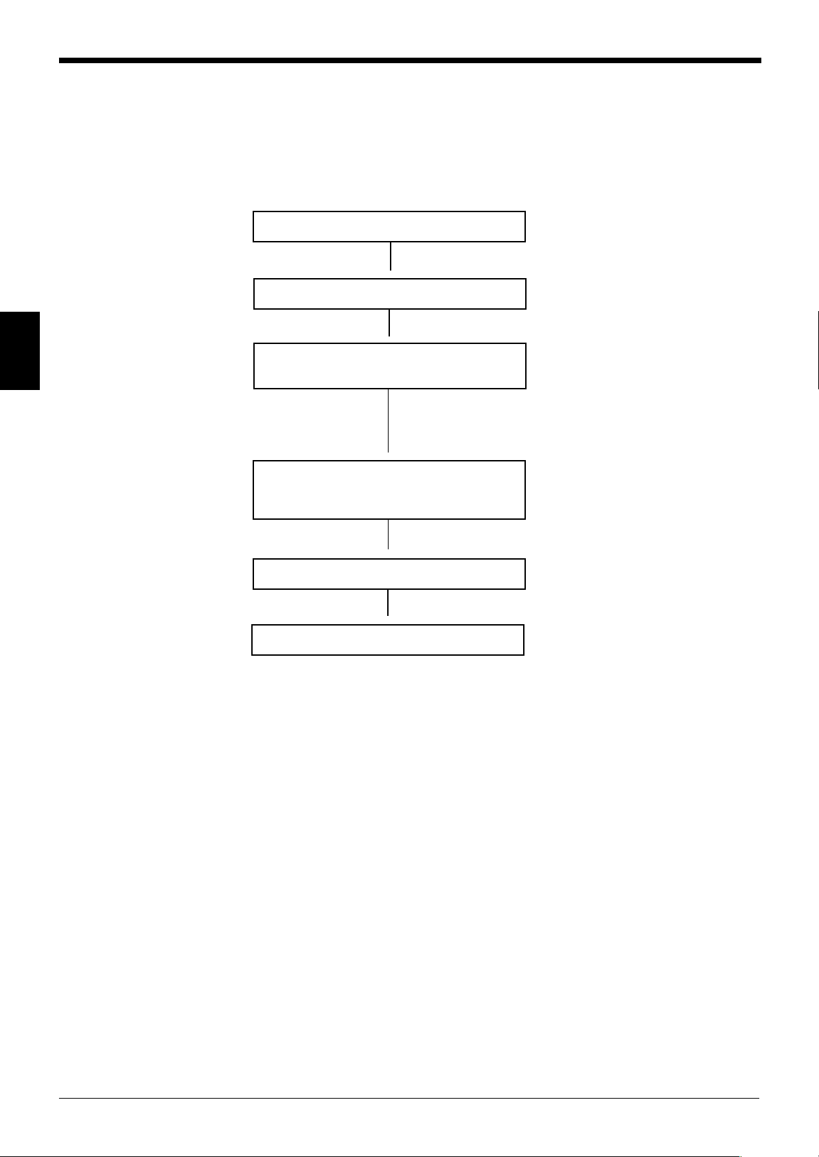
3.1.1 Procedure for Starting Measurement
3
Connect the controller and scanning head.
▲
Turn the power on.
▲
Align the optical axis of the transmitter and
receiver.
▲
The 5001 series starts laser emission in
approximately 5 seconds, at which time the
measurement begins.
▲
Place a target in the measuring area.
▲
The measured value is soon displayed.
For information on the connection
procedure, see p. 8.
• When the transmitter and receiver are
fixed to the scanning head mounting
frame, optical axis alignment is not
necessary.
• For information on the scanning head
mounting allowance, see p. 18.
For information on checking the optical
axis, see p. 60 and 61.
For information on the measuring area,
see p. 115.
The factory setting for the number of
averaging measurements is 768 for DIA
mode.
Before changing the measuring mode or the number of averaging measurements,
read this instruction manual thoroughly for the correct settings.
For setting items, see the table of contents.
The following is reference page numbers for typical operations.
• Changing the DIA mode to EDGE mode ............................................... p.39, 40
• Changing the number of averaging measurements ............................... p.44, 45
• Changing the measuring mode ........................................................... p.46 to 51
• Simultaneous measurement ........................................................................p.32
• (X + Y)/2 measurement using two scanning heads ............................... p.41, 42
16
Page 23

Chapter 4
Installation
4.1 Mounting the Scanning Head ............................................18
4.2 Mounting the Controller ..................................................... 19
Page 24

Chapter 4 Installation
Transmitter Receiver
Transmitter Receiver
Within ±1 mm
Within ±1 mm
Transmitter Receiver
Transmitter Receiver
Within ±1 mm
Within ±1 mm
Receiver
Receiver
Within ±0.25° Within ±0.25°
Within ±0.25° Within ±0.25°
Transmitter
Transmitter
Receiver
Transmitter
Transmitter
Receiver
4.1 Mounting the Scanning Head
The LS-5000 series comes with the transmitter and receiver fixed to the scanning
head mounting frame. To use the LS-5000 series with the transmitter and receiver
removed from the mounting frame, mount the scanning head so that the following
specifications are met. This will eliminate measurement errors caused by optical
axis misalignment.
Allowance for Mounting the Scanning Head
■ Horizontal deviation of transmitter and receiver positions
4
■ Inclination of transmitter and receiver
* Values in parentheses are for the LS-5121.
Note: For information on the optical axis checking function, see “Head Inspection”
on p. 60.
18
Page 25

4.2 Mounting the Controller
DIN rail
LS-5121T
SCANNING AREA
LS-5121R
SCANNING AREA
This section describes how to mount the controller (LS-5001).
Mounting the LS-5001
The LS-5001 can be mounted to a DIN rail.
Hook the upper claw first, and then press the controller against the DIN rail until it
clicks.
Chapter 4 Installation
4
Mounting the Scanning Head Front Protection Cover (For LS-5121)
Application example of front protection cover
Transmitter
The LS-5121 transmitter and receiver come with a protection cover for the scanning head.
Mount the cover as shown in order to prevent the front glass of the scanning head
from being scratched or broken.
Receiver
19
Page 26

Chapter 4 Installation
4
20
Page 27

Chapter 5
Outline of Measurements
5.1 Area/Segment/Edge ............................................................ 22
5.2 Normal Mode ....................................................................... 22
5.2.1 DIA Mode ............................................................................... 23
5.2.2 T.EDGE (TOP EDGE) Mode /
B.EDGE (BOTTOM EDGE) Mode ......................................... 23
5.2.3 SEG (m,n) Mode .................................................................... 23
5.3 Pitch Mode ........................................................................... 24
Page 28

Chapter 5 Outline of Measurements
Edge 0
Edge 1
Edge 2
Edge 3
Edge 4
Edge 5 (n-1)
Edge 6 (n)
Photodiode for synchronization
Laser
scanning
direction
Target
Transmitter Receiver
Photodiode for synchronization
Transmitter Receiver
Roller
Rotating
This width can be
measured when
SEG(m,n) is set to (0,2) in
Normal mode.
5.1 Area/Segment/Edge
When a target is placed in the measuring area, there are areas where the laser
beam is received (laser beam enters the receiver), and where the laser beam is
interrupted by the target (shadow of the target is projected on the receiver). The
border between the light and dark areas is called “EDGE”. Each section divided by
the edge is called a “SEGMENT”. The measurement "AREA" is determined by two
edges and includes all "SEGMENTS" between these two edges.
* The edge number is counted in the laser scanning direction starting at T.EDGE
(top edge).
5
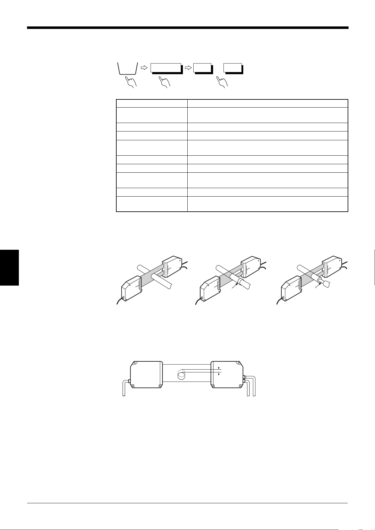
5.2 Normal Mode
Note: EDGE 0
The position of the photodiode for synchronization is called “EDGE 0”.
EDGE 0 can be used as a reference point during roller oscillation measurement or
sheet edge control. (No reference edge is required.)
Example: Roller oscillation measurement
➮
For the setting procedure, see p. 39.
The LS-5000 series has two measuring modes; NORMAL and PITCH. NORMAL
mode provides four types of measurement3: “DIA”, “T.EDGE (Top Edge)”,
“B.EDGE (Bottom Edge)” and “SEG(m,n)”.
The function of each mode is described below. Select the mode that suits your
measurement condition.
DIA mode
Measurement of outer diameter
of rod or electric wire
22
T.EDGE/B.EDGE modes
Measurement of gap
between rollers or position
of target
edge
SEG(m,n) mode
Setting the measurement
position to measure inner
diameter using
a bearing
Page 29

5.2.1 DIA Mode
Photodiode for synchronization
Laser
scanning
direction
Target
Measured
width
Transmitter Receiver
Photodiode for synchronization
Target
Measured
width
Transmitter Receiver
Photodiode for synchronization
Target
The T.EDGE mode
measures this width.
The B.EDGE mode
measures this width.
Transmitter Receiver
Photodiode for synchronization
Target
Both the T.EDGE and B.EDGE
modes measure this width.
Transmitter Receiver
Photodiode for synchronization
Target
This width is measured
when SEG(3,4) is set.
Transmitter Receiver
0
1
2
3
4
5
6
Chapter 5 Outline of Measurements
Example: Outer diameter measurement using a rod or transparent object
The width between the lower edge of the first light segment and the top edge of the
last light segment is measured.
• When one target is measured
• When several targets are measured
5.2.2 T.EDGE (TOP EDGE) Mode / B.EDGE (BOTTOM EDGE) Mode
Example: Measurement of a gap between rollers
T.EDGE: Measures the width of the first light segment.
B.EDGE: Measures the width of the last light segment.
5.2.3 SEG (m,n) Mode
Example: Inner diameter measurement using a bearing
When two edges are specified, the width between these edges is measured.
5
* (m,n) indicates any number between 0 and 254. “m” should be smaller than “n”.
Note: DIA mode
Since DIA mode is basically intended for outer diameter measurement of a rod,
transparent tube or other round surface, the measurement error due to the round
surface is calibrated.
To perform outer diameter measurement of a round target, select DIA mode.
23
Page 30

Chapter 5 Outline of Measurements
LASER ON DISPLAY DATA PITCH P. 1
HEAD1OKMax
Min
0.5010
0.4990
HEAD2OKMax
Min
0.6010
0.5990
HEAD3OKMax
Min
0.7020
0.6980
HEAD4OKMax
Min
0.8020
0.7980
SCREEN
DISPLAY
DATA
LIMIT
SETUP
PROGRAM OPTIONS
DISPLAY
DATA
Pitch
Optical axis
5.3 Pitch Mode
➮
For the setting procedure, see p. 72.
Pitch mode enables pitch measurement using connector pins or IC leads.
This mode measures each center-to-center pitch, and displays the maximum and
minimum values.
5
Note 1: When Pitch mode is selected, only one measurement can be performed
with one scanning head.
Note 2: When Pitch mode is selected, the comparator output is activated as shown
below:
HI3 = Alarm output
HI2 = Disabled
HI1 = Output when the measured value exceeds the upper/lower limit.
GO = Output when the measured value is within the upper/lower limit.
LO1: Disabled
LO2: Disabled
LO3: Disabled
24
The analog output and RS-232C output are activated as shown below.
Analog output: Held at +10V.
RS-232C output: Output according to the command.
➮
See p. 97.
Page 31

Chapter 6
Normal Mode
6.1 Normal Mode Screens ........................................................ 26
6.2 Initial Screen ....................................................................... 27
6.3 Setting Measuring Mode .................................................... 28
6.4 Setting Functions ............................................................... 29
1 [HOLD] Hold Function .................................................... 30
2 [ZERO] Auto-zero Function ............................................ 31
3 [SCREEN] Screen Selection Function ........................... 32
4 Limit Setup ..................................................................... 35
5 [CALIB] Calibration Setup .............................................. 36
6 [PROGRAM] Program Selection Function ..................... 38
7 Area Setup ..................................................................... 39
8 Calculation Setup ........................................................... 41
9 Average .......................................................................... 44
0 Measuring Mode............................................................. 46
A Digit Suppression Function ............................................ 54
B Offset Function ............................................................... 55
C Analog Output Function.................................................. 57
D I/O Slot Setup ................................................................. 59
E Inspection ....................................................................... 60
F One-scan Mode .............................................................. 62
G Program Selection Method Setup .................................. 64
H Display Unit .................................................................... 65
I Area Check Function ...................................................... 66
J Initialize .......................................................................... 67
K Mode Change ................................................................. 68
Page 32
Chapter 6 Normal Mode
LASER ON SCREEN
NOR
MAL
P. 1
DISPLAY DATA
DISPLAY DATA
DISPLAY GRAPH
DISPLAY GRAPH
ONOUT1
SET SET
OFFOUT2
OUT1
OFFOUT3
OFFOUT4
LASER ON DISPLAY GRAPHOUT1
NOR
MAL
P. 1
SETUP SCREEN
40.0000
0.0000
DATA: 25.77110
AREA
OUT1
OUT4
OUTPUT
INSPECT
UTILITY
LASER ON DISPLAY DATA
NOR
MAL
P. 1
OUT1 HI3
HI1 20.0000
LO1 15.0000
OFF
OFF
ZERO
HOLD
SCREEN
SCREEN
DISPLAY
DATA
DISPLAY
DATA
LIMIT
SET UP
PROGRAMCALIB
OPTIONS
54.21595
LASER ON SELECT OUTPUT
NOR
MAL
P. 1
DISPLAY
DATA
LIMIT
SET UP
LIMIT
SET UP
PROGRAMCALIB
OPTIONS
OUT1
OUT2
OUT3
OUT4
Select Output No. to set the limits.
LASER ON AREA SETUP
NOR
MAL
P. 1
DIAHEAD1
( 2, 3)
ESCHELP
SET
HEAD No.
EDGE No.
A1
SEGMENT
DIAHEAD2
( 2, 3)
SET
HEAD No.
EDGE No.
A2
SEGMENT
SEGMENT
SEGMENT
DIAHEAD3
( 2, 3)
SET
HEAD No.
EDGE No.
A3
DIAHEAD4
( 2, 3)
SET
HEAD No.
EDGE No.
A4
OUTPUT MODEOUT1LASER ON P. 1
+A1 OFF OFF OFF
AREA1 AREA2 AREA3 AREA4
100
AVERAGE
CALCULATE
1 (0.833ms)
MEASURING MODE
SELF-TIMING
INTERVAL (ms)
NORMAL
DIGIT
SUPPRESS
NONE
ESCHELP NEXT
NOR
MAL
HEAD1
HEAD4
LASER ON CALIBRATE AREA
NOR
MAL
P. 1
DISPLAY
DATA
LIMIT
SET UP
PROGRAMCALIB
CALIB
PROGRAM
OPTIONS
OPTIONS
AREA1
AREA2
AREA3
AREA4
Select Area No. to calibrate.
LASER ON OUTPUT MODE
NOR
MAL
P. 1
OUT1
OUT2
OUT3
I/O SLOT
SETUP
OUT4
ESC
Select Output to set.
LASER ON I/O SLOT SETUP
NOR
MAL
P. 1
I/O OUT1
OUT2
OUT1
OUT2
SLOT1 CH1
I/O
I/O
I/O
CH2
SLOT2 CH1
CH2
ESC
I/O SLOT SETUP
LASER ON SELECT PROGRAM No.
NOR
MAL
P. 1
DISPLAY
DATA
LIMIT
SET UP
PROGRAMCALIB
OPTIONS
Selected program No.
1
5 87642 31
13 1615141210 119
LASER ON INSPECT
NOR
MAL
P. 1
HEAD1
HEAD2
HEAD3
HEAD4
ESC
Select Head to inspect.
INSPECTHEAD1LASER ON P. 1
BEAM INTENSITY
HEAD R
: OK
: OKOPTICAL AXIS
ESC
NOR
MAL
LASER ON OPTIONS
NOR
MAL
P. 1
DISPLAY
DATA
LIMIT
SET UP
PROGRAMCALIB OPTIONS
AREA
OUTPUT
INSPECT
UTILITY
Select Option to setup.
MODE
CHANGE
Normal
-> Pitch
LASER ON UTILITY
NOR
MAL
P. 1
AREA CHECK
INITIALIZE
ON
PANEL
mm
ONE-SCAN MODE
PROGRAM SELECT
DISPLAY UNIT
ESC
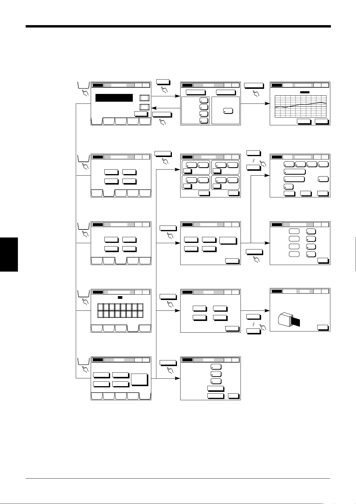
6.1 Normal Mode Screens
DISPLAY DATA screen
➮
See p.30.
LIMIT SETUP screen
➮
See p.35.
CALIBRATE screen
SCREEN SELECT screen DISPLAY GRAPH screen
➮
See p. 33.
➮
See p. 33.
AREA SETUP screen OUTPUT MODE screen
➮
See p.41-58.
I/O SLOT SETUP screen
➮
See p.39.
OUTPUT MODE screen
6
➮
See p.36.
SELECT PROGRAM NO.
screen
➮
See p.38.
OPTIONS screen
➮
See p.39.
➮
See p.41.
INSPECT screen
➮
See p.60.
UTILITY screen
➮
See p.62-68.
➮
See p.59.
HEAD INSPECT screen
➮
See p.60.
26
Page 33

6.2 Initial Screen
LASER ON DISPLAY DATA
NOR
MAL
P. 1
OUT1 54.21595
HI1 20.0000
LO1 15.0000
HI3
OUT2 54.21595
HI1 20.0000
LO1 15.0000
HI3
OFF OFF
ZERO HOLD
OUT3 54.21595
HI1 20.0000
LO1 15.0000
HI3
OUT4 54.21595
HI1 20.0000
LO1 15.0000
HI3
SCREEN
DISPLAY
DATA
LIMIT
SETUP
PROGRAMCALIB
OPTIONS
Chapter 6 Normal Mode
Displays the measured
value, comparator output
and upper/lower limits
(HI1, LO1) for OUT1.
Auto-zero switch
Laser ON/OFF
status
To the DISPLAY
DATA screen
To the LIMIT
SETUP screen
Screen title
To the CALIB
screen
Measuring
mode
To the
SELECT
PROGRAM
NO. screen
Program No.
Hold switch
Screen
selecting
switch
To the
OPTION S
screen
6
27
Page 34
Chapter 6 Normal Mode
LASER ON AREA SETUP
NOR
MAL
P. 1
DIAHEAD1
( 2, 3)
ESCHELP
SET
HEAD No.
EDGE No.
A1
SEGMENT SEGMENT
SEGMENT SEGMENT
DIAHEAD2
( 2, 3)
SET
HEAD No.
EDGE No.
A2
DIAHEAD1
( 2, 3)
SET
HEAD No.
EDGE No.
A3
DIAHEAD1
( 2, 3)
SET
HEAD No.
EDGE No.
A4
AREA
OPTIONS
A3
A4
A1
A2
DIAHEAD2
( 2, 3)
SET
HEAD No.
EDGE No.
A2
SEGMENT
Set the measurement mode
[DIA, T.EDGE, B.EDGE, SEG(m,n)].
(AREA SETUP
screen)
A2 (Measuring area 2)
Set the scanning
head number (1 to 4).
OUTPUT MODEOUT1LASER ON P. 1
+A1 OFF OFF OFF
AREA1 AREA2 AREA3 AREA4
100
AVERAGE
CALCULATE
1 (0.833ms)
MEASURING MODE
SELF-TIMING
INTERVAL (ms)
NORMAL
DIGIT
SUPPRESS
NONE
ESCHELP NEXT
NOR
MAL
OUTPUT
OPTIONS
Digit
Calculation
No. of Averaging
Measurements
Measurement
mode
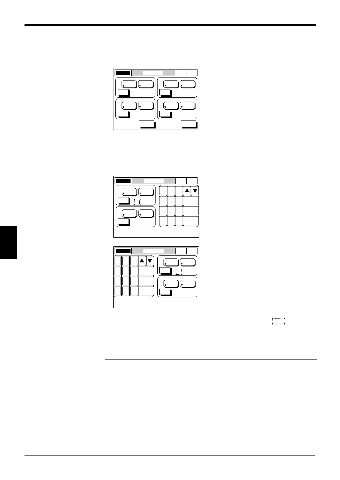
6.3 Setting Measuring Mode
Setting Scanning Head and Measurement
1. Setting Measuring Area
The LS-5000 series can simultaneously perform four measurements and outputs
with one scanning head, and different measurements and outputs with four scanning heads.
The place for which the measurement condition is set is called the “measuring
area” (A1 to A4), where the scanning head number and measuring mode can be
set.
(➮ See note.)
6
28
Note: The LS-5002 and 5502 can only control a single scanning head.
2. Setting Output Mode
The LS-5000 series can accept measurement data from multiple scanning heads
and perform calculations on the data for displaying and outputting the comparator
result.
Using the preset measuring area (A1 to A4), you can set various calculation and
measuring modes, as well as the number of averaging measurements as shown
below.
Page 35
Chapter 6 Normal Mode
LASER ON DISPLAY DATA
NOR
MAL
P. 1
OFF OFF
ZERO HOLD
SCREEN
DISPLAY
DATA
LIMIT
SETUP
PROGRAMCALIB
OPTIONS
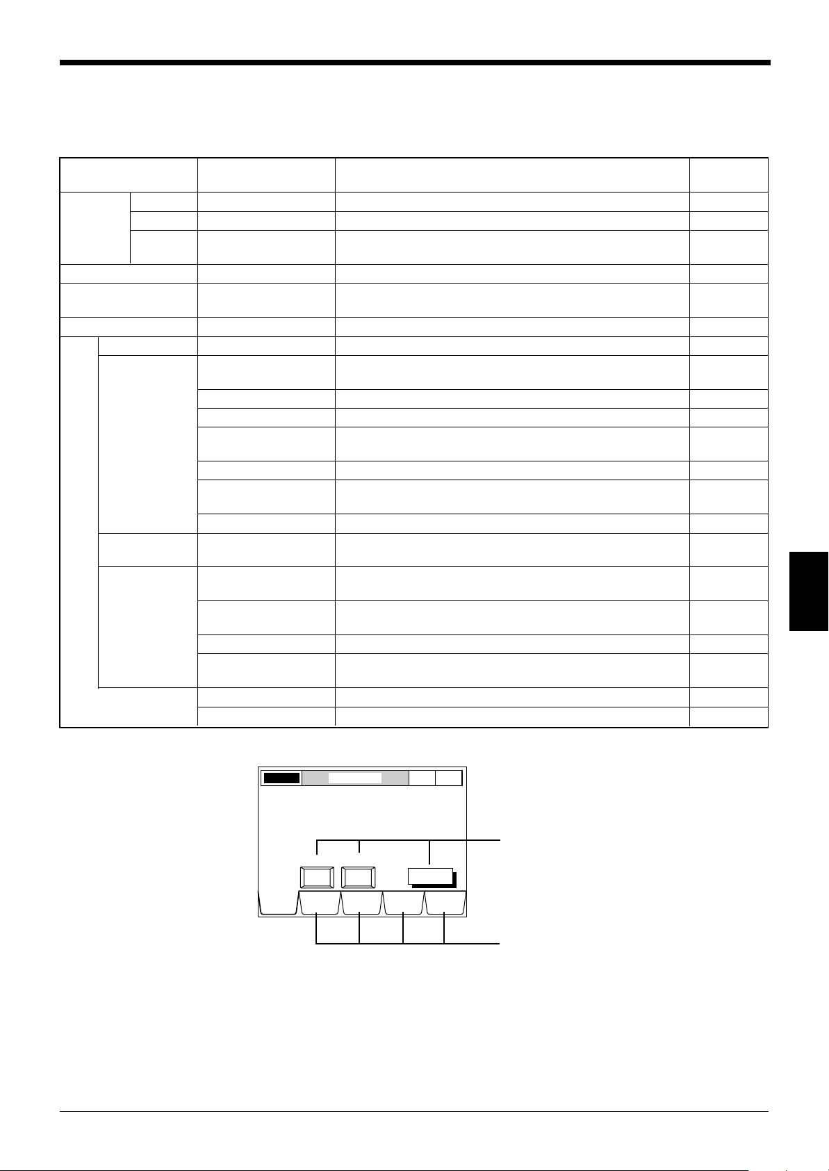
Button
Tag
6.4 Setting Functions
Names and functions
Tag/Button Function Description Reference
page
DISPLAY HOLD Hold A measured value can be held or reset. 30
DATA ZERO Auto-zero A measured value can be instantaneously reset to “0.000”. 31
SCREEN Screen Selection The DISPLAY DATA screen or DISPLAY GRAPH screen 32 to 34
can be selected.
LIMIT SETUP Limit Setup 7 level tolerance limits can be set for each output. 35
CALIB Calibration Setup Minute measurement fluctuations caused by a change in the 36
target surface condition or target inclination can be corrected.
PROGRAM Program Selection Measurement data is stored and called as programs. 38
AREA Area Setup DIA, T.EDGE, B.EDGE or SEG(m,n) can be selected. 39
OUTPUT Calculation Setup Calculation can be performed with each measuring area 41
(A1 to A4).
Average Measurement results can be averaged. 44
M. Mode Nine measuring modes are provided. 46 to 53
Offset Any value can be added to or subtracted from the displayed 55
value.
Digit Sets the number of digits after the decimal point. 54
Analog Output An analog voltage (within ±10 V) proportional to the displayed 57
value can be output.
I/O Slot Setup Expansion I/O boards can be set. 59
INSPECT Inspect The scanning head conditions (optical axis, intensity) can 60
OPTIONS
UTILITY One-Scan Function Data obtained with only one surface of the 12-surface polygon 62
Program Selection The program selection method (front panel or rear terminals) 64
Display Unit The display units can be selected (“mm” or “inch”). 65
Area Check The number of edges in the measuring area can be 66
Initialize All settings are reset to the initial values. 67
Mode Change Normal mode or Pitch mode can be selected. 68
be checked.
mirror becomes effective.
can be selected.
checked.
6
29
Page 36

Chapter 6 Normal Mode
DISPLAY
DATA
OFF
HOLD HOLD
ON
LASER ON DISPLAY DATA
NOR
MAL
P. 1
OUT1 54.21595
HI1 20.0000
LO1 15.0000
HI3
OUT2 54.21595
HI1 20.0000
LO1 15.0000
HI3
OFF OFF
ZERO HOLD
OUT3 54.21595
HI1 20.0000
LO1 15.0000
HI3
OUT4 54.21595
HI1 20.0000
LO1 15.0000
HI3
SCREEN
DISPLAY
DATA
LIMIT
SETUP
PROGRAMCALIB
OPTIONS
LASER ON DISPLAY DATA
NOR
MAL
P. 1
OUT1 54.21595
HI1 20.0000
LO1 15.0000
HI3
OUT2 54.21595
HI1 20.0000
LO1 15.0000
HI3
OFF ON
ZERO HOLD
OUT3 54.21595
HI1 20.0000
LO1 15.0000
HI3
OUT4 54.21595
HI1 20.0000
LO1 15.0000
HI3
SCREEN
DISPLAY
DATA
LIMIT
SETUP
PROGRAMCALIB
OPTIONS
11
1 [HOLD] Hold Function
11
The hold function allows the displayed value and output value to be held or reset
regardless of the measuring mode.
■ Setting Procedure
1. Select the DISPLAY DATA screen.
Press the [DISPLAY DATA] button. The screen shown below is displayed.
6
2. Set the hold function.
Press the [HOLD OFF] button. [HOLD OFF] is changed to [HOLD ON].
Note: The hold function cannot be set separately for each output from this screen.
To set this function separately for each output, send the hold signal from the
control I/O board (Option). (Short-circuit the Tim input terminal and the GND
terminal.)
30
Page 37

22
DISPLAY
DATA
OFF
ZERO ZERO
ON
LASER ON DISPLAY DATA
NOR
MAL
P. 1
OUT1 54.21595
HI1 20.0000
LO1 15.0000
HI3
OUT2 54.21595
HI1 20.0000
LO1 15.0000
HI3
OFF OFF
ZERO HOLD
OUT3 54.21595
HI1 20.0000
LO1 15.0000
HI3
OUT4 54.21595
HI1 20.0000
LO1 15.0000
HI3
SCREEN
DISPLAY
DATA
LIMIT
SETUP
PROGRAMCALIB
OPTIONS
LASER ON DISPLAY DATA
NOR
MAL
P. 1
OUT1 0.00000
0.00000
0.00000
0.00000
HI1 20.0000
LO1 15.0000
LO1
OUT2
HI1 20.0000
LO1 15.0000
LO1
OFF
ON
ZERO HOLD
OUT3
HI1 20.0000
LO1 15.0000
LO1
OUT4
HI1 20.0000
LO1 15.0000
LO1
SCREEN
DISPLAY
DATA
LIMIT
SETUP
PROGRAMCALIB OPTIONS
2 [ZERO] Auto-zero Function
22
The auto-zero function can instantaneously reset the displayed value to “0.0000”.
This function simplifies zero-point adjustment when targets are changed over.
■ Setting Procedure
1. Select the DISPLAY DATA screen.
Chapter 6 Normal Mode
Press the [DISPLAY DATA] button. The screen below is displayed.
2. Set the auto-zero function.
Press the [ZERO OFF] button. [ZERO OFF] is changed to [ZERO ON].
The following two methods will also activate the auto-zero input.
• Short-circuit the auto-zero input terminal and the GND terminal of the control I/O
board (Option).
The auto-zero function can be set separately for each output.
• Send a command through the RS-232C board from external equipment such as
a computer.
You can reset the auto-zero function by sending the command.
➮
See p. 93.
Note 1: The auto-zero function cannot be reset with the control I/O input.
6
Note 2: When the displayed value is “- - - - -”, the auto-zero function cannot be
activated.
Note 3: When the auto-zero function is activated from the front panel, all outputs
are simultaneously reset to “0.0000”.
31
Page 38

Chapter 6 Normal Mode
LASER ON DISPLAY DATA
NOR
MAL
P. 1
OUT1 54.21595
HI1 20.0000
LO1 15.0000
HI3
OUT2 54.21595
HI1 20.0000
LO1 15.0000
HI3
OFF OFF
ZERO HOLD
OUT3 54.21595
HI1 20.0000
LO1 15.0000
HI3
OUT4 54.21595
HI1 20.0000
LO1 15.0000
HI3
SCREEN
DISPLAY
DATA
LIMIT
SETUP
PROGRAMCALIB
OPTIONS
DISPLAY
DATA
SCREEN DISPLAY DATA DISPLAY GRAPHor
OUT1 54.21595 H13 OUT3 5421595 H13
HI
LO
OUT2 54.21595 H13 OUT4 5421595 H13
HI
LO
HI
LO
HI
LO
200000
200000
200000
200000
200000
200000
200000
200000
33
3 [SCREEN] Screen Selection Function
33
The screen selection function allows you to select the DISPLAY DATA screen (1 to
4 data displays) or the DISPLAY GRAPH screen.
<DISPLAY DATA>
Example 1: When several scanning heads are used
6
<DISPLAY GRAPH>
Example 2: Measurement of wire’s outer diameter
■ Setting Procedure <DISPLAY DATA>
1. Select the DISPLAY DATA screen.
Press the [DISPLAY DATA] button. The screen shown below is displayed.
32
2. Select the SCREEN SELECT screen.
Press the [SCREEN] button.
Page 39

Chapter 6 Normal Mode
OUT1 OUT2 OUT3 OUT4
LASER ON SCREEN
NOR
MAL
P. 1
DISPLAY DATA DISPLAY GRAPH
ONOUT1
SET SET
OFFOUT2
OUT1
OFFOUT3
OFFOUT4
LASER ON DISPLAY GRAPHOUT1
NOR
MAL
P. 1
SETUP SCREEN
40.0000
0.0000
DATA: 25.77110
LASER ON SCREEN
NOR
MAL
P. 1
DISPLAY DATA DISPLAY GRAPH
ONOUT1
SET SET
OFFOUT2
OUT1
OFFOUT3
OFFOUT4
3. Set the output to be displayed. (
➮
For setting outputs, see p.41.
)
Turn ON the output to be displayed.
If an output is not to be displayed, press the [ON] button once to turn it OFF.
4. Return to the DISPLAY DATA screen.
Press the [DISPLAY DATA] button to return to the DISPLAY DATA screen.
■ Setting Procedure <DISPLAY GRAPH>
1. Perform steps 1 and 2 described on the previous page to go to the SCREEN
SELECT screen shown below.
2. Select “DISPLAY GRAPH”.
Select the output to be graphically displayed.
OUT1 to OUT4 are switched in the above order.
Press the [DISPLAY GRAPH] button.
3. Perform “GRAPH SETUP”.
Press the [SETUP] button.
6
33
Page 40
Chapter 6 Normal Mode
LASER ON SETUPOUT1
NOR
MAL
P. 1
RANGE
TIME
MAX:
MIN:
40.0000
0.0000
SAMPLING
FREQ:
NO. OF DATA:
1 X 0.1S
100
SETUPOUT2LASER ON
NOR
MAL
P. 1
87
5 64
2 31
0
9
ENTER
CANCEL
ESCAPE
MAX: 40.0000
MIN:
SAMPLING
FREQ:
NO. OF DATA:
0.0000
1 X 0.
100
SETUPOUT1LASER ON
NOR
MAL
P. 1
87
5 64
2 31
. -0
9
ENTER
CANCEL
ESCAPE
MAX: 40.0000
MIN:
SAMPLING
FREQ:
NO. OF DATA:
0.0000
1 X 0.
100
4. Set the range of GRAPH display.
Perform “RANGE SETUP”. Press the [RANGE] button.
6
Select the item from MAX or MIN using the [▲] [ ] arrow keys.
▲
Enter a value using the numeric keys and press [ENTER].
Press [ESCAPE] to complete the entry.
Press [CANCEL] to cancel the entry. The
value returns to the previous value.
5. Perform “TIME SETUP”.
Press the [TIME] button. Select the item from SAMPLING FREQ or NO. OF
DATA using the [▲] [ ] arrow keys. Enter a value using the numeric keys and
▲
press [ENTER].
Press [ESCAPE] to complete the entry.
Press [CANCEL] to cancel the entry. The
value returns to the previous value.
34
Note 1: Range Setup
The maximum and minimum range setup values are as follows:
Max.: 999.9999 (9.99999)
Min.: -99.9999 (-0.99999)
* Values in ( ) are the maximum and minimum values displayed in inches.
When the displayed value exceeds the above range, “OVER” is displayed and the
entered value cannot be accepted.
Note 2: Time Setup
The maximum and minimum values for the sampling frequency and the number of
displayed data are as follows:
Sampling frequency
Max.: 30000 x 0.1 s (3000 s) Min.: 1 (0.1 s)
Number of displayed data
Max.: 600 Min.: 2
When the sampling frequency or the number of displayed data exceeds the above
range, “OVER” is displayed and the entered value cannot be accepted.
Note 3: The above maximum and minimum values are independent of tolerance
limits.
Page 41
44
OUT1 • • • OUT4
LIMIT
SETUP
LASER ON SELECT OUTPUT
NOR
MAL
P. 1
DISPLAY
DATA
LIMIT
SETUP
PROGRAMCALIB
OPTIONS
OUT1
OUT2
OUT3
OUT4
Select Output No. to set the limits.
LIMIT SETUPOUT1LASER ON
NOR
MAL
P. 1
87
5 64
2 31
. -0
9
ENTER
CANCEL
ESCAPE
HI3 30.0000
HI2 25.0000
HI3 20.0000
LO1 15.0000
LO2 10.0000
LO3 5.0000
4 Limit Setup
44
Chapter 6 Normal Mode
7-level-tolerance-limits can be set separately for four outputs. (
setting output
.)
➮
See p.41 for
■ Setting Procedure
1. Select the LIMIT SETUP screen.
Press the [LIMIT SETUP] button. The screen shown below is displayed.
2. Set tolerance limits.
Press the button corresponding to the output for which you wish to set tolerance
limits.
6
Select a desired tolerance limit using the [▲]/[ ] arrow keys.
Enter a value using the numeric keys, and press [ENTER].
Press [ESCAPE] to complete the entry.
Press [CANCEL] to cancel the entry. The value returns to the previous value.
Note 1: When a measured value exceeds the tolerance range, the measured value
is displayed in reverse. The differentiation result corresponding to the tolerance
limits is output from the display unit and the control I/O (option) board.
Note 2: Tolerance limits must conform to the following condition:
HI3 > HI2 > HI1 > LO3 > LO2 > LO1
Otherwise, the tolerance value cannot be entered. (The “ERR” message appears
on the display and the entered value cannot be accepted.)
Note 3: The maximum and minimum tolerance limit values are as follows:
Max.: 999.9999 (9.99999)
Min.: -99.9999 (-0.99999)
* Values in ( ) are the maximum and minimum values displayed in inches.
▲
35
Page 42
Chapter 6 Normal Mode
AREA1CALIB • • • AREA4
CALIBRATEAREA2LASER ON
NOR
MAL
P. 1
DATA
54.21595
ESC
CALIBRATE
RESET
LASER ON CALIBRATE AREA
NOR
MAL
P. 1
DISPLAY
DATA
LIMIT
SETUP
PROGRAMCALIB
OPTIONS
AREA1
AREA2
AREA3
AREA4
Select Segment No. to calibrate.
CALIBRATEAREA1LASER ON
NOR
MAL
P. 1
87
5 64
2 31
.0
9
ENTER
CANCEL
ESCAPE
TARGET1 0.0000
DATA 54.21595
TARGET1 0.0000
Enter calibration
values for targets
1 and 2, and press
OK.
OK
55
5 [CALIB] Calibration Setup
55
Minute measurement fluctuations caused by a change in the target surface condition or target inclination can be corrected with each AREA. (
AREA.
)
➮
See p.39 for setting
■ Setting Procedure
1. Select the CALIBRATE AREA screen.
Press the [CALIB] button. The screen shown below is displayed.
6
2. Press the button corresponding to the area for which you wish to perform
calibration.
Press the [RESET] button to reset the calibration. The calibration value is reset
to the factory setting.
Press the [CALIBRATE] button to go to the CALIBRATE screen.
36
3. Insert sample workpiece 1 to check the measured value.
Enter the value of sample workpiece 1 using the numeric keys, and accept the
value by pressing the [ENTER] button.
Page 43

Chapter 6 Normal Mode
4. Insert sample workpiece 2 to check the measured value.
Enter the value of sample workpiece 2 using the numeric keys, and accept the
value by pressing the [ENTER] button.
When you press the [OK] button, the calibration is performed and a message
regarding the calibration result is displayed.
Input Conditions
Workpiece 1 < Workpiece 2
0.5 ≤ Span ≤ 2
If the above conditions are not satisfied, the “Calibration Error” message is
displayed.
When the above conditions are satisfied, the “Calibration OK” message is
displayed.
6
37
Page 44

Chapter 6 Normal Mode
P1 P2 P3 P4 GND
• • •
PROGRAM
1 16
LASER ON SELECT PROGRAM No.
NOR
MAL
P. 1
DISPLAY
DATA
LIMIT
SETUP
PROGRAMCALIB
OPTIONS
Selected program No.
1
5 87642 31
13 1615141210 119
66
6 [PROGRAM] Program Selection Function
66
The LS-5000 series can store all measurement conditions as a program. Up to 16
programs can be stored and loaded easily.
■ Setting Procedure
1. Select the SELECT PROGRAM NO. screen.
Press the [PROGRAM] button.
2. Select a program number.
Press the button corresponding to the program number to be loaded.
6
38
Note 1: When the program selection method is set to the rear terminals, the
program number cannot be switched on the front panel.
➮
See p. 63.
Note 2: To switch a program number using the rear terminals, change the combination of the following four terminals and GND terminal.
Terminal No.
Program No. P1 P2 P3 P4
1 OFF OFF OFF OFF
2ONOFF OFF OFF
3 OFF ON OFF OFF
4ONONOFF OFF
5 OFF OFF ON OFF
6ONOFF ON OFF
7 OFF ON ON OFF
8ONONONOFF
9 OFF OFF OFF ON
10 ON OFF OFF ON
11 OFF ON OFF ON
12 ON ON OFF ON
13 OFF OFF ON ON
14 ON OFF ON ON
15 OFF ON ON ON
16 ON ON ON ON
ON: This terminal and the GND terminal are short-circuited.
OFF: This terminal is open.
Note 3: The system setup for the display unit (
➮
see p. 104
) cannot be stored by
the program function.
Page 45
77
LASER ON OPTIONS
NOR
MAL
P. 1
DISPLAY
DATA
LIMIT
SETUP
PROGRAMCALIB OPTIONS
AREA
OUTPUT
INSPECT
UTILITY
Select Option to setup.
MODE
CHANGE
Normal
-> Pitch
LASER ON AREA SETUP
NOR
MAL
P. 1
DIAHEAD1
( 2, 3)
ESCHELP
SET
HEAD No.
EDGE No.
A1
SEGMENT SEGMENT
SEGMENT SEGMENT
DIAHEAD2
( 2, 3)
SET
HEAD No.
EDGE No.
A2
DIAHEAD3
( 2, 3)
SET
HEAD No.
EDGE No.
A3
DIAHEAD4
( 2, 3)
SET
HEAD No.
EDGE No.
A4
HEAD1 HEAD2 HEAD3 HEAD4
DIA
T. EDGE B. EDGE
SEG
OPTIONS
AREA
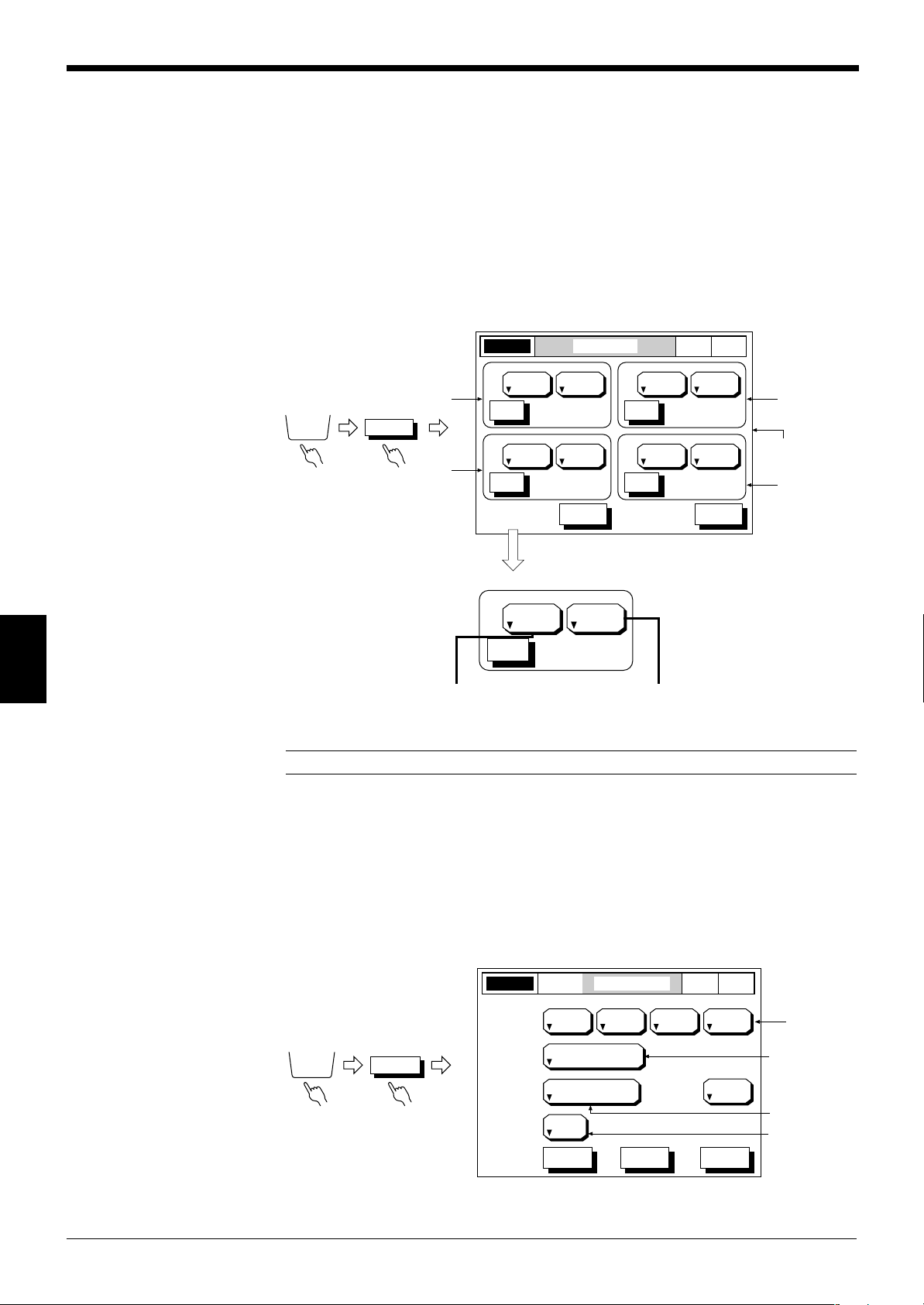
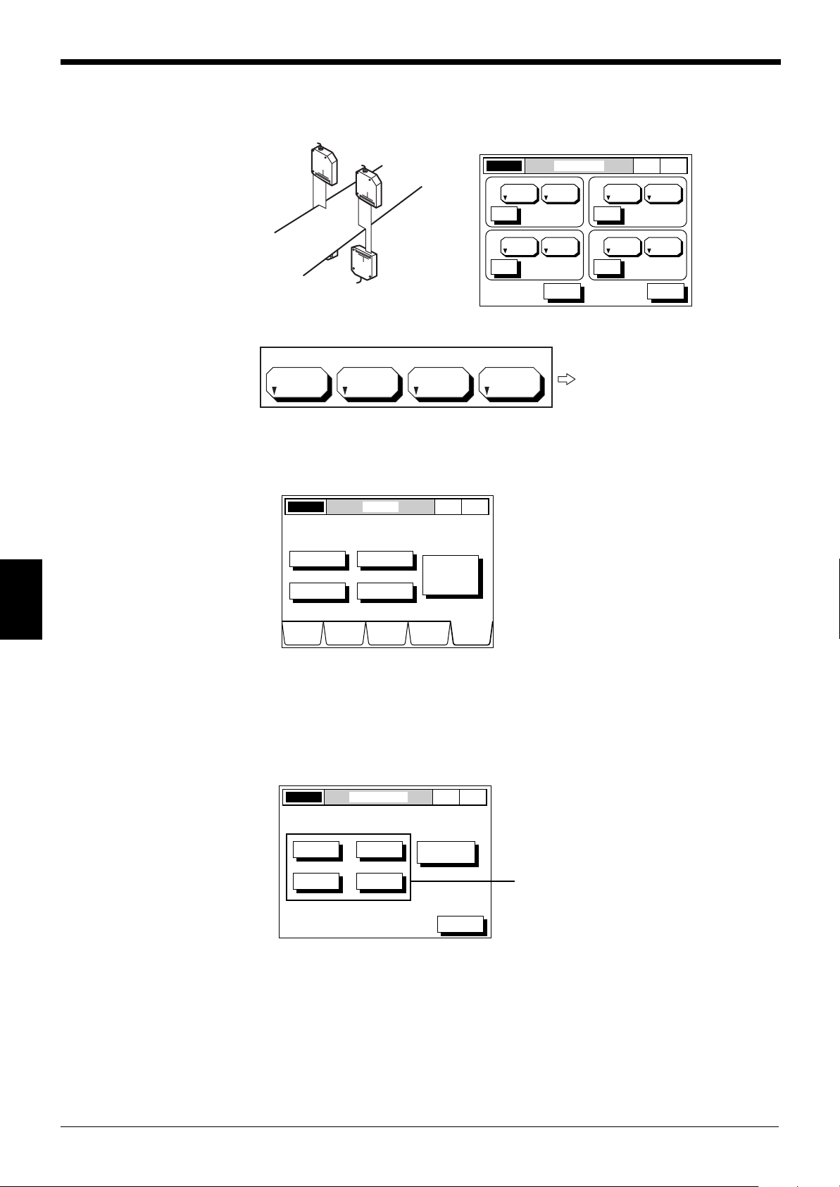
7 Area Setup
77
Chapter 6 Normal Mode
The scanning head (Head 1 to Head 4) and measuring mode (DIA, T.EDGE,
B.EDGE, SEG(m,n))can be selected for a measuring area. Up to 4 areas can be
set at the same time. (
➮
see p. 22 for Area.
)
■ Setting Procedure
1. Select the OPTIONS screen.
Press the [OPTIONS] button.
2. Select the AREA SETUP screen.
Press the [AREA] button.
3. Set the scanning head number.
When you press the [HEAD No.] button, the scanning head number is switched
in the following order.
4. Set the segment.
When you press the [SEGMENT] button, the segment is switched in the following order.
6
Note 1: The edge number setting is effective only when “SEG” is selected as the
SEGMENT.
Note 2: When either of DIA, T.EDGE, or B.EDGE is selected for a scanning head,
SEG cannot be selected for the same head. Also, when SEG is selected, DIA,
T.EDGE, and B.EDGE cannot be selected for the same head.
Note 3: When only one scanning head is connected, the head number remains
“HEAD 1” even if the head number button is pressed.
39
Page 46
Chapter 6 Normal Mode
LASER ON AREA SETUP
NOR
MAL
P. 1
SEGHEAD1
( 2, 3)
ESCHELP
SET
HEAD No. SEGMENT
SEGMENT SEGMENT
SEGMENT
EDGE No.
A1
SEGHEAD1
( 2, 3)
SET
HEAD No.
EDGE No.
A2
SEGHEAD1
( 2, 3)
SET
HEAD No.
EDGE No.
A3
SEGHEAD1
( 2, 3)
SET
HEAD No.
EDGE No.
A4
LASER ON AREA SETUP
NOR
MAL
P. 1
SEGHEAD1
( 2 , 3)
SET
HEAD No.
EDGE No.
A1
SEGMENT
SEGMENT
SEGHEAD1
( 2, 3)
SET
HEAD No.
EDGE No.
A2
87
5 64
2 31
. -0
9
ENTER
CANCEL
ESCAPE
( 2 , 3)
LASER ON AREA SETUP
NOR
MAL
P. 1
SEGHEAD1
SET
HEAD No.
EDGE No.
A3
SEGMENT
SEGMENT
SEGHEAD1
( 2, 3)
SET
HEAD No.
EDGE No.
A4
87
5 64
2 31
. -0
9
ENTER
CANCEL
ESCAPE
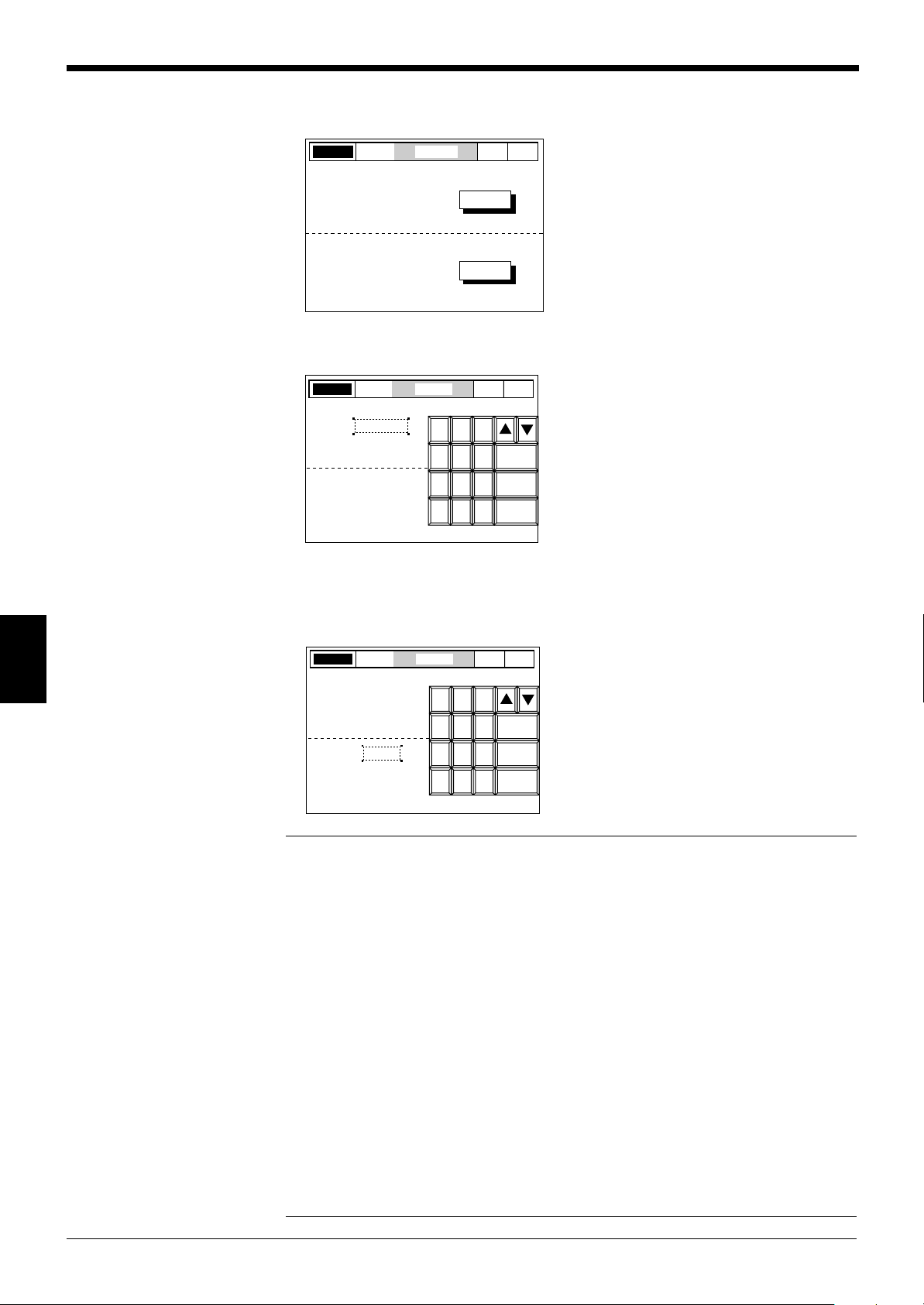
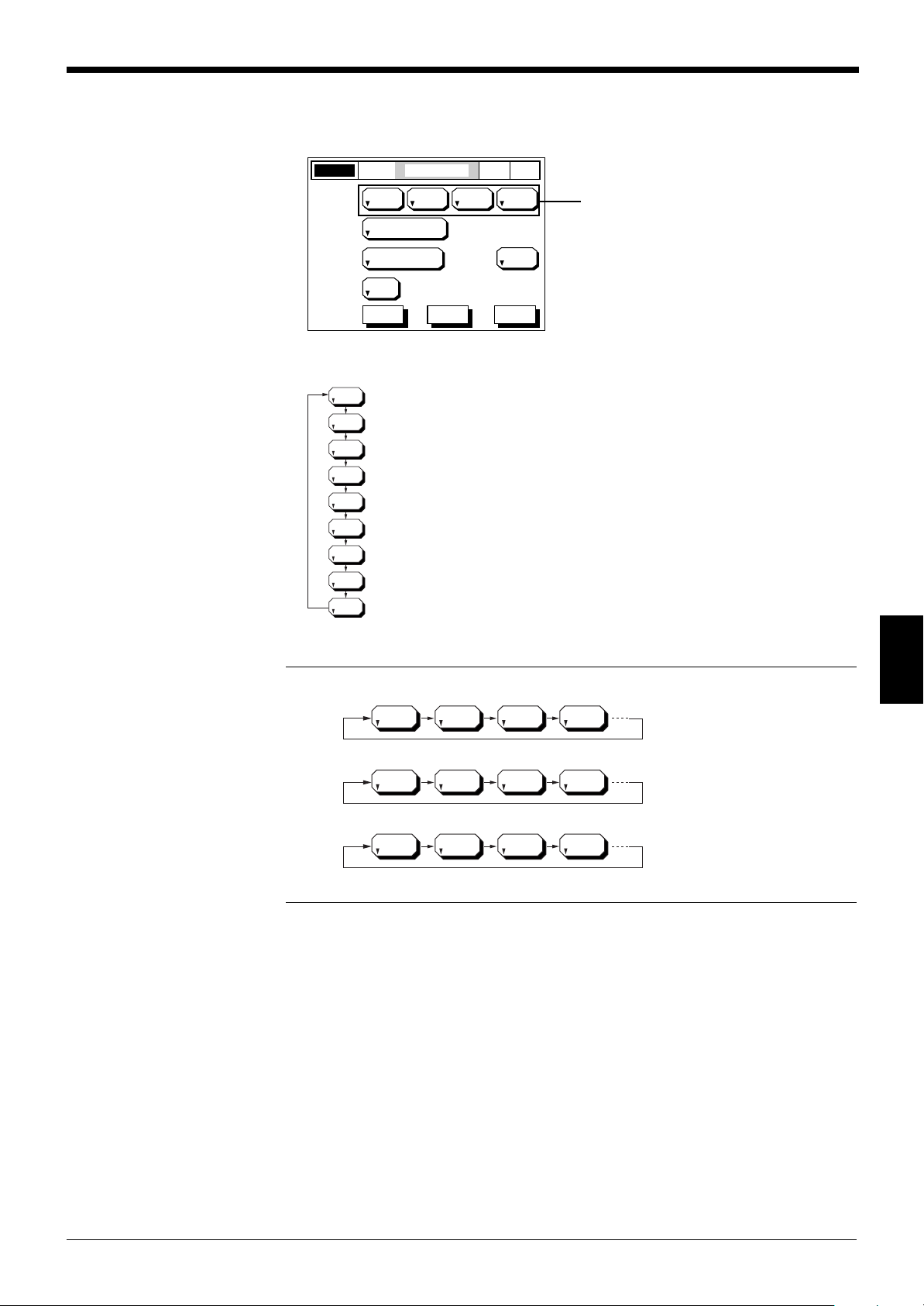
■ Procedure for Setting Edge Number (Only when SEG is selected.)
1. Select the AREA SETUP screen.
Perform steps 1 and 2 described on the previous page to go to the screen
shown below.
2. Set the EDGE number.
Press the [SET] button corresponding to the area for which you wish to set the
edge number.
6
You can enter a value in the space indicated by the dotted line .
Enter a value using the numeric keys, and press [ENTER] key.
Press [ESCAPE] to complete the entry.
Press [CANCEL] to cancel the entry. The value returns to the previous value.
Note 1: The edge number (m,n) must conform to the condition: m < n.
When “m” is larger than “n”, the “ERR” message is displayed and the entered value
cannot be accepted.
Note 2: When you press the [HELP] button, descriptions about the measuring mode
(DIA, T.EDGE/B.EDGE and SEG) are displayed on the screen.
40
Page 47

88
OPTIONS
OUTPUT OUT1 • • • OUT4
OUTPUT MODEOUT1LASER ON P. 1
+A1 +A2 +A3 OFF
AREA1 AREA2 AREA3 AREA4
500
AVERAGE
CALCULATE
1 (0.833ms)
MEASURING MODE
SELF-TIMING
INTERVAL (ms)
NORMAL
DIGIT
SUPPRESS
NONE
ESCHELP NEXT
NOR
MAL
+A1 +A2 –A3 OFF
AREA1 AREA2 AREA3 AREA4
LASER ON AREA SETUP
NOR
MAL
P. 1
EDGEI
EDGEI
HEAD1
( 2, 3)
ESCHELP
SET
HEAD No.
EDGE No.
A1
SEGMENT
HEAD2
( 2, 3)
SET
HEAD No.
EDGE No.
A2
SEGMENT
DIAHEAD3
( 2, 3)
SET
HEAD No.
EDGE No.
A3
SEGMENT
DIAHEAD4
( 2, 3)
SET
HEAD No.
EDGE No.
A4
SEGMENT
+A1/2 +A2/2 OFF OFF
AREA1 AREA2 AREA3 AREA4
8 Calculation Setup
88
Chapter 6 Normal Mode
The following calculation modes can be set for the area (A1 to A4) specified on the
AREA SETUP screen. Addition and subtraction using data of several areas can be
set.
■ Calculation for each area
OFF : The measured value is not used for calculation.
+A# : The measured value is output without changes.
+A#/2 : The measured value is multiplied by “1/2”.
+A#/3 : The measured value is multiplied by “1/3”.
:
–A#/4 : The measured value is multiplied by “-1/4”.
* A# indicates either of A1 to A4.
Calculation using data of several areas
Calculation setup
When the calculation modes are set as shown above, the calculation result of
“+A1+(+A2)+(-A3)” is output.
[Example 1]
When two scanning heads are installed along two axes, the average value of the
wire’s outer diameter is output.
[AREA SETUP]
6
Setting Status
1/2 of the outer diameters
measured with HEAD 1 and
HEAD 2 are added.
41
Page 48
Chapter 6 Normal Mode
LASER ON AREA SETUP
NOR
MAL
P. 1
EDGEI
EDGEI
HEAD1
( 2, 3)
ESCHELP
SET
HEAD No.
EDGE No.
A1
SEGMENT
HEAD2
( 2, 3)
SET
HEAD No.
EDGE No.
A2
SEGMENT
DIAHEAD3
( 2, 3)
SET
HEAD No.
EDGE No.
A3
SEGMENT
DIAHEAD4
( 2, 3)
SET
HEAD No.
EDGE No.
A4
SEGMENT
–A1 –A2 OFF OFF
AREA1 AREA2 AREA3 AREA4
LASER ON OPTIONS
NOR
MAL
P. 1
DISPLAY
DATA
LIMIT
SETUP
PROGRAMCALIB OPTIONS
AREA
OUTPUT
INSPECT
UTILITY
Select Option to setup.
MODE
CHANGE
Normal
-> Pitch
LASER ON OUTPUT MODE
NOR
MAL
P. 1
OUT1
OUT2
OUT3
I/O SLOT
SETUP
OUT4
ESC
Select Output to set.
[Example 2]
Two scanning heads are used to measure a sheet width.
[AREA SETUP]
Setting Status
The measured values of HEAD
1 and HEAD 2 are both multiplied by “-1”, and the resulting
values are added.
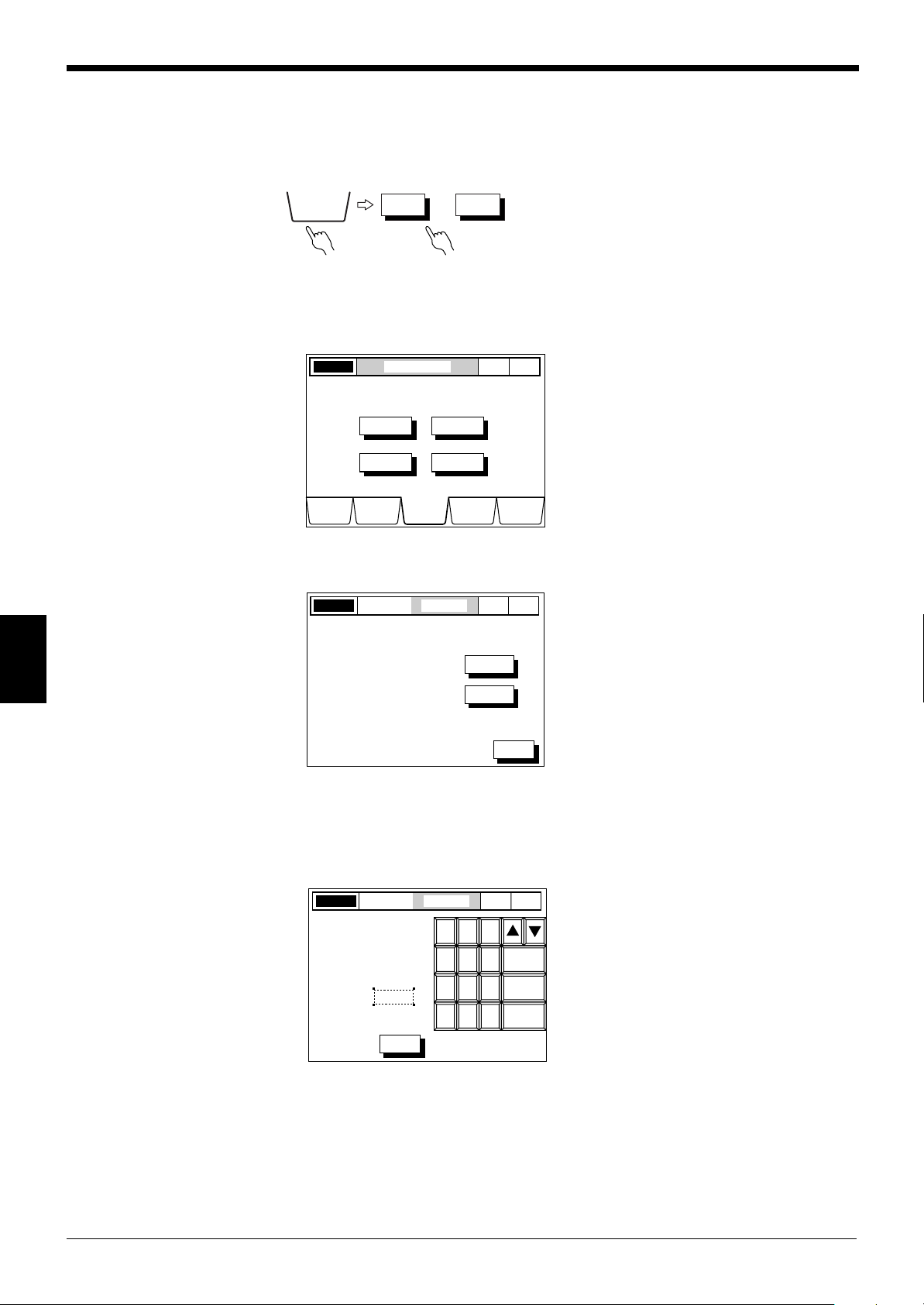
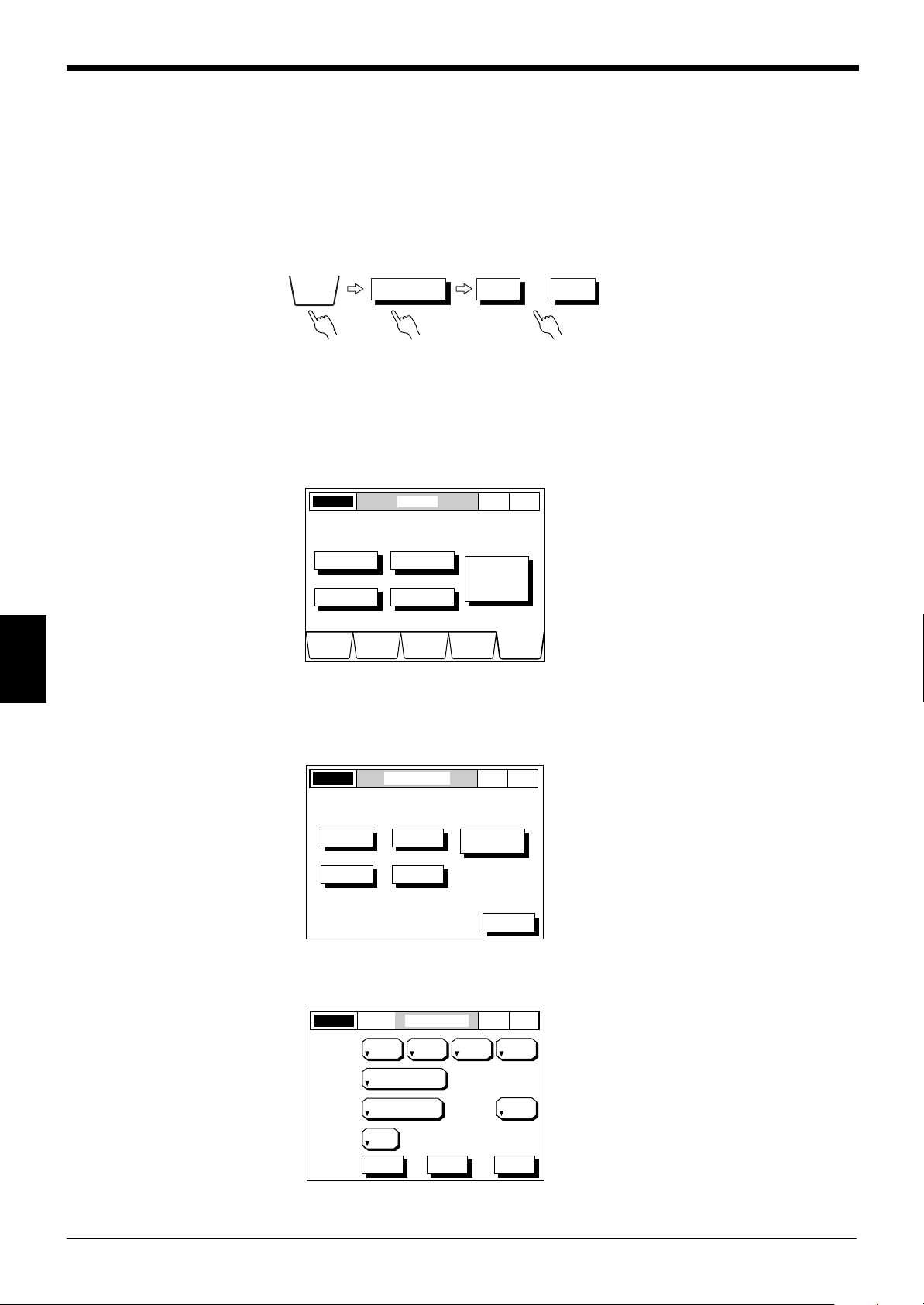
■ Setting Procedure
1. Select the OUTPUT MODE screen.
Press the [OPTIONS] button. The screen shown below is displayed.
6
2. Select the output number to be set.
Press the [OUTPUT] button.
Press the button corresponding to the output number for which calculation setup
is to be performed.
[OUTPUT] button
42
Page 49
Chapter 6 Normal Mode
OFF
–A1/4
+A1
+A1/2
+A1/3
+A1/4
–A1
–A1/2
–A1/3
OFF +A2 +A2/2 +A2/3
OFF +A3 +A3/2 +A3/3
OFF +A4 +A4/2 +A4/3
For AREA 2
For AREA 3
For AREA 4
OUTPUT MODEOUT1LASER ON P. 1
+A1 OFF OFF OFF
AREA1 AREA2 AREA3 AREA4
100
AVERAGE
CALCULATE
1 (0.833ms)
MEASURING MODE
SELF-TIMING
INTERVAL (ms)
NORMAL
DIGIT
SUPPRESS
NONE
ESCHELP NEXT
NOR
MAL
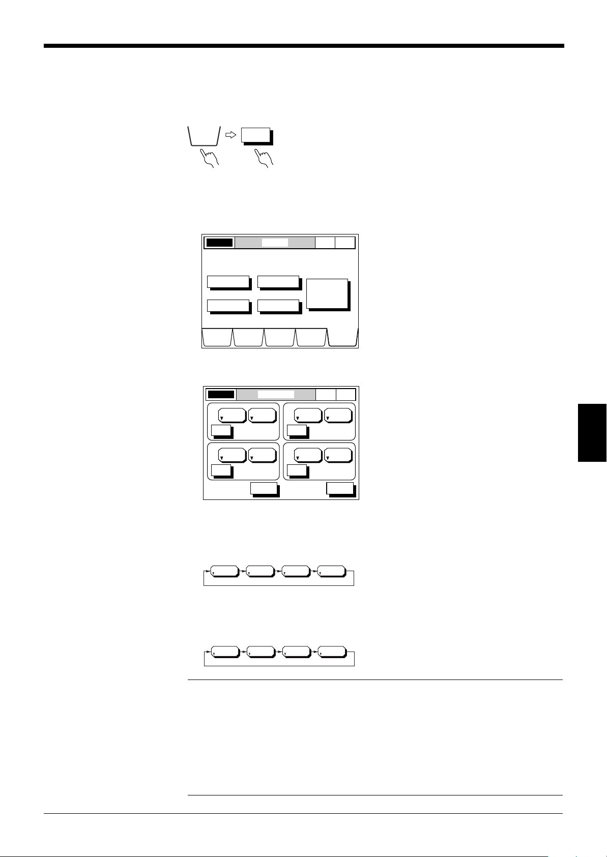
3. Set the calculation modes.
Every time you press the [CALCULATE] button, the setting changes as shown
below. (For AREA 1)
[CALCULATE] button
OFF: Calculation is set to OFF.
+A1: The measured value is output without changes.
+A1/2: The measured value is multiplied by “1/2”.
+A1/3: The measured value is multiplied by “1/3”.
+A1/4: The measured value is multiplied by “1/4”.
Note:
–A1: The measured value is multiplied by “–1”.
–A1/2: The measured value is multiplied by –1/2”.
–A1/3: The measured value is multiplied by “–1/3”.
–A1/4: The measured value is multiplied by “–1/4”.
6
43
Page 50
Chapter 6 Normal Mode
OPTIONS
OUTPUT OUT1 • • • OUT4
LASER ON OPTIONS
NOR
MAL
P. 1
DISPLAY
DATA
LIMIT
SETUP
PROGRAMCALIB OPTIONS
AREA
OUTPUT
INSPECT
UTILITY
Select Option to setup.
MODE
CHANGE
Normal
-> Pitch
LASER ON OUTPUT MODE
NOR
MAL
P. 1
OUT1
OUT2
OUT3
I/O SLOT
SETUP
OUT4
ESC
Select Output to set.
OUTPUT MODEOUT1LASER ON P. 1
+A1 OFF OFF OFF
AREA1 AREA2 AREA3 AREA4
100
AVERAGE
CALCULATE
1 (0.833ms)
MEASURING MODE
SELF-TIMING
INTERVAL (ms)
NORMAL
DIGIT
SUPPRESS
NONE
ESCHELP NEXT
NOR
MAL
99
9 Average
99
The number of averaging measurements can be set based on the application as
follows.
• Increase the number of averaging measurements:
To average fluctuations in measured values to obtain stable data
• Reduce the number of averaging measurements:
To increase high speed differentiation speed
■ Setting Procedure
1. Select the OPTIONS screen.
Press the [OPTIONS] button.
2. Select the OUTPUT MODE screen.
Press the [OUTPUT] button.
6
3. Set the number of averaging measurements.
Press the button corresponding to the output number for which the number of
averaging measurements is to be set.
Press the [AVERAGE] button and set a number of averaging measurements.
44
Page 51

Chapter 6 Normal Mode
[Relationship between number of averaging measurements and averaging time]
No. of averaging Averaging time
measurements
1 0.833 ms
2 1.67 ms
4 3.33 ms
8 6.67 ms
12 10 ms
24 20 ms
48 40
Note: The averaging time is not the same as output response time.
➮
For output response time, see p. 121.
No. of averaging Averaging time
measurements
96 80 ms
192 160 ms
384 320 ms
768 640 ms
1538 1.28 s
3072 2.56 s
6144 5.12 s
6
45
Page 52
Chapter 6 Normal Mode
Measures
this diameter.
Measures
this diameter.
Measures
this width.
OPTIONS
OUTPUT OUT1 • • • OUT4
00
0 Measuring mode
00
The LS-5000 series provides the following nine measuring modes.
Mode Description
Normal The measured value and comparator output are displayed/
output at any time.
Peak hold The maximum value during a specified period is measured.
Bottom hold The minimum value during a specified period is measured.
Difference hold The difference between the maximum and minimum values
during a specified period is measured.
Auto peak hold The maximum measured value is retained.
Auto bottom hold The minimum measured value is retained.
Auto difference hold The difference between the maximum and minimum values is
retained.
Sample hold The instantaneous value at a specified time is measured.
Self-timing Automatic measurement without using external synchronous
input. Only with DIA or SEG (m, n).
6
[Applications of each mode]
• Normal mode
Used for normal continuous measurement.
• Difference hold
• Auto difference hold
• Peak hold
• Auto peak hold
Used to measure the maximum value of the target.
• Bottom hold
• Auto bottom hold
Used to measure the
minimum value of the
target.
46
Page 53

Chapter 6 Normal Mode
LASER ON OPTIONS
NOR
MAL
P. 1
DISPLAY
DATA
LIMIT
SETUP
PROGRAMCALIB OPTIONS
AREA
OUTPUT
INSPECT
UTILITY
Select Option to setup.
MODE
CHANGE
Normal
-> Pitch
LASER ON OUTPUT MODE
NOR
MAL
P. 1
OUT1
OUT2
OUT3
I/O SLOT
SETUP
OUT4
ESC
Select Output to set.
NORMAL PEAK BOTTOM DIFFERENCE
AUTO-DIFFERENCE AUTO-BOTTOM AUTO-PEAK SELF-TIMING SAMPLE
OUTPUT MODEOUT1LASER ON P. 1
+A1 OFF OFF OFF
AREA1 AREA2 AREA3 AREA4
100
AVERAGE
CALCULATE
1 (0.833ms)
MEASURING MODE
SELF-TIMING
INTERVAL (ms)
NORMAL
DIGIT
SUPPRESS
NONE
ESCHELP NEXT
NOR
MAL
500 1000 10 50 100 200
■ Setting Procedure
1. Select the OPTIONS screen.
Press the [OPTIONS] button.
2. Select the OUTPUT MODE screen.
Press the [OUTPUT] button.
Press the button corresponding to the output number for which the measuring
mode is to be set.
3. Set the measuring mode.
Press the [MEASURING MODE] button to set the measuring mode.
Every time the [MEASURING MODE] button is pressed, the indication changes
in the above order.
[When the self-timing mode is selected] [Only with DIA or SEG (m, n)]
4. Set the self-timing interval.
Press the [SELF-TIMING INTERVAL] button to set the self-timing interval.
Every time the [SELF-TIMING INTERVAL] button is pressed, the setting
changes in the following order.
6
47
Page 54

Chapter 6 Normal Mode
* When the synchronous input is ON, the displayed value/comparator output is retained.
Preset upper limit
Displayed value
Preset lower limit
HI OUT
ON
OFF
ON
OFF
ON
OFF
ON
OFF
GO OUT
LO OUT
Synchronous
input
(t)
Internal
measurement
Measured
value
ON
OFF
Synchronous
input
Power-ON or
RESET input
(t)
After the power-ON or RESET input is activated,
“-----” is displayed until the synchronous input is turned ON.
Peak hold value
Sampling
period
Sampling
period
Sampling
period
Note 1: The self-timing setting is effective only when self-timing mode is selected.
Note 2: The self-timing interval should be set longer than the averaging time.
Note 3: Self-timing mode is enabled only when DIA or SEG(m,n) is selected.
(When T.EDGE or B.EDGE is selected, self-timing mode is disabled.)
● Normal mode
The measurement value/comparator output can be displayed/output at any time.
Timing Diagram
6
● Peak hold mode
The maximum value during a specified period can be measured.
The sampling period is the duration between the falling edge and the next rising
edge of the synchronous input.
Timing Diagram
48
Note: When the reset input terminal and the GND terminal are short-circuited, the
retained value is reset and measurement starts again.
Page 55
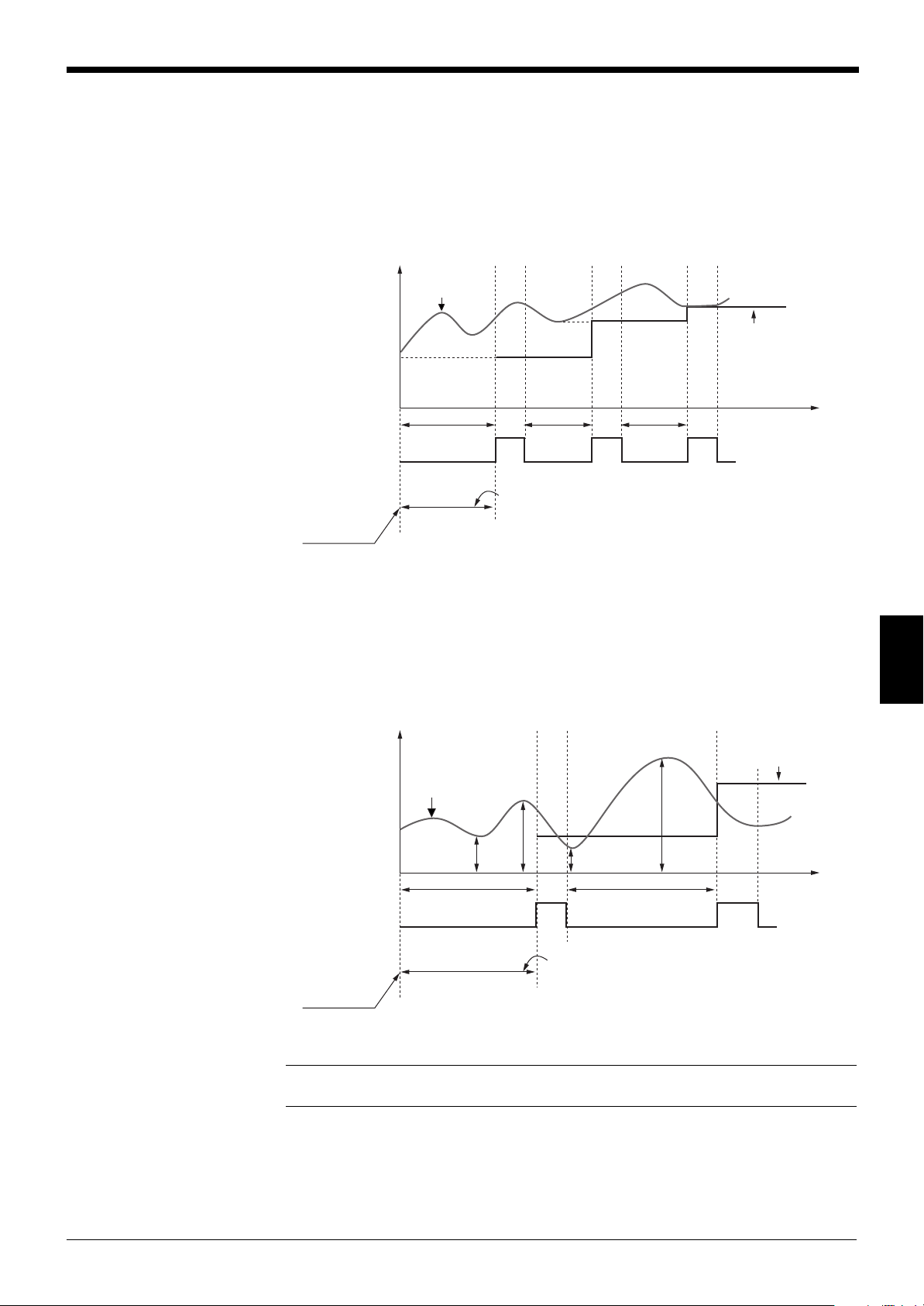
Chapter 6 Normal Mode
ON
OFF
Synchronous
input
Power-ON or
RESET input
(t)
After the power-ON or RESET input is activated,
“-----” is displayed until the synchronous input is turned ON.
Bottom hold
displayed value
Sampling
period
Sampling
period
Sampling
period
Internal
measurement
Measured
value
ON
OFF
Synchronous
input
Measured
value
Power-ON or
RESET input
(t)
After the power-ON or RESET input is activated,
“-----” is displayed until the synchronous input is
turned ON.
Difference hold
displayed value
Sampling
period
Sampling
period
Internal
measurement
b
b'
P
P'
(P-b)
(P'-b')
● Bottom hold mode
The minimum value during a specified period can be measured.
The sampling period is the duration between the falling edge and the next rising
edge of the synchronous input.
Timing Diagram
● Difference mode
The difference between the maximum and minimum values during a specified
period can be measured.
6
Timing Diagram
Note: When the reset input terminal and the GND terminal are short-circuited, the
retained value is reset to the present value and measurement starts again.
49
Page 56

Chapter 6 Normal Mode
ON
OFF
Synchronous
input
ON
OFF
Reset input
(t)
Auto bottom hold value
Measured
value
Internal
measurement
ON
OFF
Synchronous
input
ON
OFF
Reset input
(t)
Auto peak hold value
Internal
measurement
Measured
value
● Auto peak hold mode
The maximum value after measurement starts can be measured.
Timing Diagram
6
● Auto bottom hold mode
The minimum value after measurement starts can be measured.
Timing Diagram
Note: When the reset input terminal and the GND terminal are short-circuited, the
retained value is reset to the present value and measurement starts again.
50
Page 57

Chapter 6 Normal Mode
ON
OFF
Synchronous
input
ON
OFF
Power-ON or
RESET input
(t)
Auto difference
hold value
Measured
value
Internal
measurement
ON
OFF
Synchronous
input
Power-ON or
RESET input
(t)
Sample hold
value
Measured
value
Internal
measurement
After the power-ON or RESET input is activated,
“-----” is displayed until the synchronous input is turned ON.
● Auto difference hold mode
The difference between the maximum and minimum values after measurement
starts can be measured.
Timing Diagram
● Sample hold mode
The instantaneous value at a specified time can be measured.
Timing Diagram
Note: When the reset input terminal and the GND terminal are short-circuited, the
retained value is reset to the present value and measurement starts again.
6
51
Page 58

Chapter 6 Normal Mode
Internal measurement
Self-timing value
No target
No target
Target enters the
measuring area
Target goes out
of the measur-
ing area
Preset
self-timing
interval
Preset
self-timing
interval
Internal
synchronous
signal
Measured
value
ON
(t)
OFF
After the power-ON or RESET input is activated,
“-----” is displayed until the internal synchronous signal is turned ON.
Target enters the
measuring area
Target goes out
of the measur-
ing area
● Self-timing mode
Measurement is automatically performed according to the internal synchronous
signal.
Timing Diagram
6
Note 1: When the self-timing hold mode is used, the external synchronous input is
ignored.
Note 2: When the reset input terminal and the GND terminal are short-circuited,
the retained value is reset and measurement starts again.
■ Target recognition method in self-timing mode
The LS-5000 series’ self-timing mode takes a specified duration to start sampleholding after the LS-5001 has recognized that a target has been placed in the
measuring area. (The target recognition method varies depending on the
SEGMENT.)
The LS-5001 can measure a target regardless of the direction it enters the
measuring area from.
52
Page 59

Chapter 6 Normal Mode
1
Edge No.
2
1
Edge No.
2
3
4
Target recognition method by measuring mode
• DIA mode: A target is recognized when the number of edges in the measuring
area is two or more.
The target has not yet been recognized.
The LS-5001 recognizes that a
target has been placed in the
measuring area when the number of
edges in the measuring area is two
or more.
• SEG (m, n) mode: A target is recognized when a specified number of edges is
generated in the measuring area.
When SEG(2,3) is set:
The target has not yet been recognized because the specified number
of edges (Edge No.) is not present in
The target has been recognized
when the specified number of edges
is generated in the measuring area.
the measuring area.
6
53
Page 60
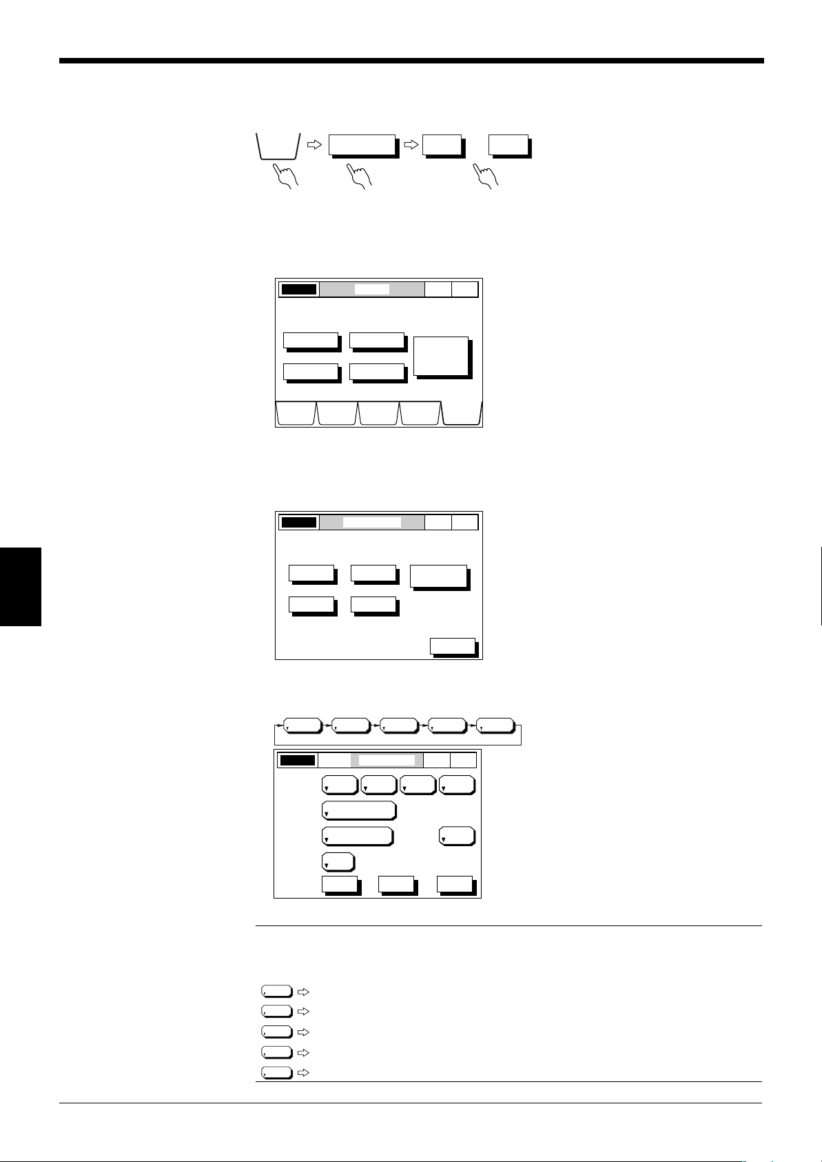
Chapter 6 Normal Mode
OPTIONS
OUTPUT OUT1 • • • OUT4
LASER ON OPTIONS
NOR
MAL
P. 1
DISPLAY
DATA
LIMIT
SETUP
PROGRAMCALIB OPTIONS
AREA
OUTPUT
INSPECT
UTILITY
Select Option to setup.
MODE
CHANGE
Normal
-> Pitch
LASER ON OUTPUT MODE
NOR
MAL
P. 1
OUT1
OUT2
OUT3
I/O SLOT
SETUP
OUT4
ESC
Select Output to set.
OUTPUT MODEOUT1LASER ON P. 1
+A1 OFF OFF OFF
AREA1 AREA2 AREA3 AREA4
100
AVERAGE
CALCULATE
1 (0.833ms)
MEASURING MODE
SELF-TIMING
INTERVAL (ms)
NORMAL
DIGIT
SUPPRESS
NONE
ESCHELP NEXT
NOR
MAL
NONE
1234
NONE
1
2
3
4
AA
A Digit Suppression Function
AA
The digits after the decimal point can be suppressed as required.
■ Setting Procedure
1. Select the OPTIONS screen. Press the [OPTIONS] button.
2. Select the OUTPUT MODE screen. Press the [OUTPUT] button.
6
3. Change the number of digits.
Press the button corresponding to the output number for which the number of
digits is to be changed.
Every time you press the [DIGIT SUPPRESS] button, the display changes in
the following order. The value indicates the number of digit to be suppressed.
54
Note: The relationship between each switch setting and the number of displayed
digits is as follows:
Example
(Displays 5 digits after the decimal point: 10.00000 mm/1.000000 inch)
(Displays 4 digits after the decimal point: 10.0000 mm/1.00000 inch)
(Displays 3 digits after the decimal point: 10.000 mm/1.0000 inch)
(Displays 2 digits after the decimal point: 10.00 mm/1.000 inch)
(Displays 1 digit after the decimal point: 10.0 mm/1.00 inch)
Page 61
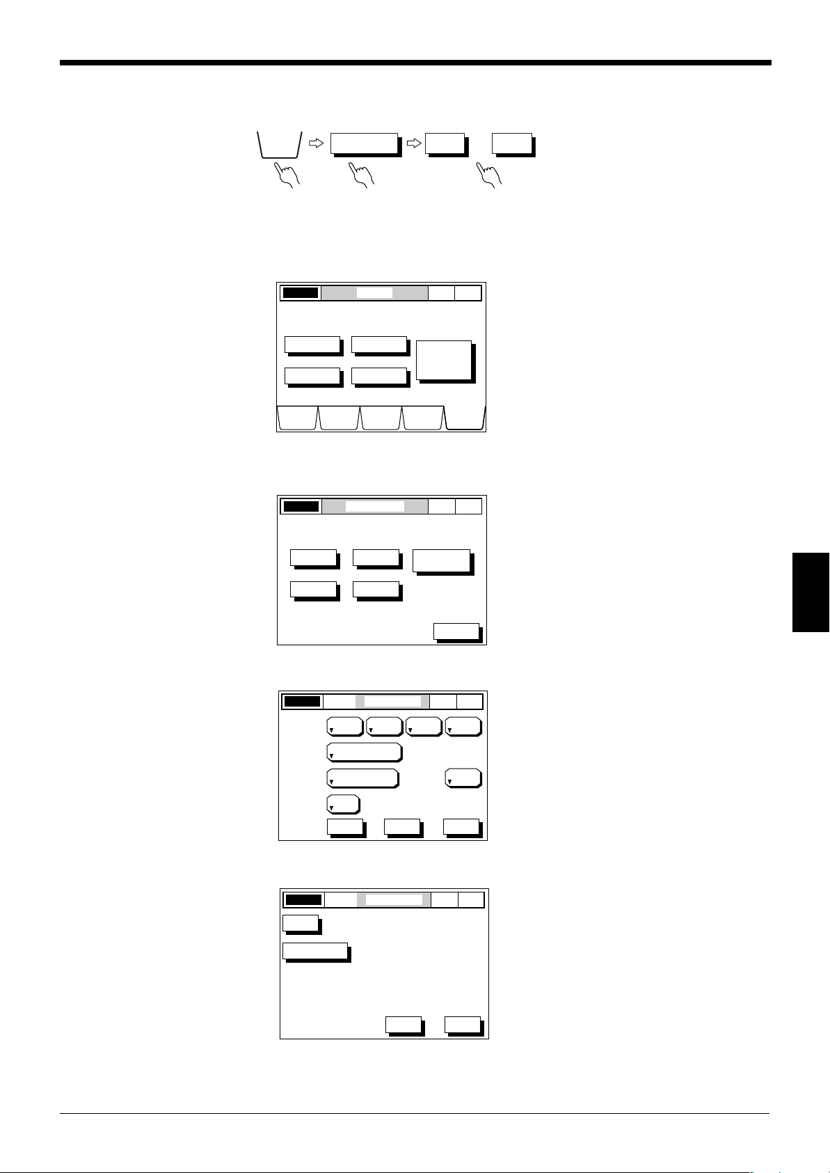
BB
OPTIONS
OUTPUT OUT1 • • • OUT4
LASER ON OPTIONS
NOR
MAL
P. 1
DISPLAY
DATA
LIMIT
SETUP
PROGRAMCALIB OPTIONS
AREA
OUTPUT
INSPECT
UTILITY
Select Option to setup.
MODE
CHANGE
Normal
-> Pitch
LASER ON OUTPUT MODE
NOR
MAL
P. 1
OUT1
OUT2
OUT3
I/O SLOT
SETUP
OUT4
ESC
Select Output to set.
OUTPUT MODEOUT1LASER ON P. 1
+A1 OFF OFF OFF
AREA1 AREA2 AREA3 AREA4
100
AVERAGE
CALCULATE
1 (0.833ms)
MEASURING MODE
SELF-TIMING
INTERVAL (ms)
NORMAL
DIGIT
SUPPRESS
NONE
ESCHELP NEXT
NOR
MAL
OUTPUT MODEOUT1LASER ON P. 1
NOR
MAL
OFFSET
+10 V=
-10 V=
40.0000
0.0000
0.0000
ANALOG OUT
ESCPREV
B Offset Function
BB
Chapter 6 Normal Mode
The desired value can be added to or subtracted from the displayed value.
■ Setting Procedure
1. Select the OPTIONS screen. Press the [OPTIONS] button.
2. Select the OUTPUT MODE screen. Press the [OUTPUT] button.
3. Press the button corresponding to the output number for which the offset
function is to be set.
4. Press the [NEXT] button.
6
5. Set the offset function. Press the [OFFSET] button.
55
Page 62

Chapter 6 Normal Mode
OUTPUT MODEOUT1LASER ON P. 1
NOR
MAL
87
5 64
2 3
.-
1
0
9
ENTER
CANCEL
ESCAPE
OFFSET
+10 V=
-10 V=
40.0000
0.0000
0.0000
ANALOG OUT
6. Enter an offset value using the numeric keys, and press [ENTER].
Press [ESCAPE] to complete the entry.
Press [CANCEL] to cancel the entry.
The value returns to the previous value.
Note: The maximum and minimum offset values are as follows:
Max.: 999.9999 (9.99999)
Min.: -99.9999 (-0.99999)
Values in ( ) are in inches.
6
56
Page 63

CC
+10 V
Analog
output
Displayed
value
-10 V
10.000 30.000
LASER ON OPTIONS
NOR
MAL
P. 1
DISPLAY
DATA
LIMIT
SETUP
PROGRAMCALIB OPTIONS
AREA
OUTPUT
INSPECT
UTILITY
Select Option to setup.
MODE
CHANGE
Normal
-> Pitch
C Analog Output Function
CC
Chapter 6 Normal Mode
An analog voltage proportional to the displayed value can be output using an
optional I/O board in the range of ±10 V.
The analog output scaling range is between -99.9999 and 999.9999 in “mm” (-
0.99999 and -99.9999 in “inch”), and the ripple is 5 mV.
● Scaling
The analog output is scaled to set the changing rate (inclination) of the analog
output relative to the displayed value. Enter a value to be displayed, relative to +10
V and -10 V respectively.
When the analog output is set to “+10 V = 30.000” and “-10 V = 10.000”, the
relation between analog output and displayed value is as follows:
Note: Resolution
The resolution of the LS-5000 series’ analog output is 5 mV. The resolution in
displayed value varies depending on the scaling.
Example 1
When the analog output is set to “+10 V = 10.000” and “-10 V = -10.000”:
20 (V) : 0.005 (V) = 20 (mm) : x (mm) x = 0.005 mm
Example 2
When the analog output is set to “+10 V = 40.000” and “-10 V = 0.0000”:
20 (V) : 0.005 (V) = 40 (mm) : x (mm) x = 0.010 mm
■ Setting Procedure
1. Select the OPTIONS screen. Press the [OPTIONS] button.
2. Select the OUTPUT MODE screen. Press the [OUTPUT] button.
6
57
Page 64

Chapter 6 Normal Mode
LASER ON OUTPUT MODE
NOR
MAL
P. 1
OUT1
OUT2
OUT3
I/O SLOT
SETUP
OUT4
ESC
Select Output to set.
OUTPUT MODEOUT1LASER ON P. 1
+A1 OFF OFF OFF
AREA1 AREA2 AREA3 AREA4
100
AVERAGE
CALCULATE
1 (0.833ms)
MEASURING MODE
SELF-TIMING
INTERVAL (ms)
NORMAL
DIGIT
SUPPRESS
NONE
ESCHELP NEXT
NOR
MAL
OUTPUT MODEOUT1LASER ON P. 1
NOR
MAL
OFFSET
+10 V=
-10 V=
40.0000
0.0000
0.0000
ANALOG OUT
ESCPREV
OUTPUT MODEOUT1LASER ON P. 1
NOR
MAL
87
5 64
2 3
.-
1
0
9
ENTER
CANCEL
ESCAPE
OFFSET
+10 V=
-10 V=
40.0000
0.0000
0.0000
ANALOG OUT
+10 V
-10 V
10.000 30.000
3. Set the analog output function.
Press the button corresponding to the output for which the analog output function is to be set.
4. Press the [NEXT] button.
6
5. Press the [ANALOG OUTPUT] button.
Using the numeric keys, enter an analog output value in the location indicated
by the dotted line.
Press [ESCAPE] to complete the entry.
Press [CANCEL] to cancel the entry.
The value returns to the previous value.
58
Note 1: When “-----” is displayed, the analog output is retained at +10 V.
Note 2: When the displayed value exceeds the preset scaling range, the analog
output is retained at +10 V. (When the displayed value falls below the scaling
range, the analog output is retained at -10 V.)
[Example]
When the analog output is set to “+10 V = 30.000” and “-10 V =
10.000”:
When the displayed value is 30 or more, the analog output is
retained at +10 V.
When the displayed value is 10 or less, the analog output is
retained at -10 V.
Page 65

DD
OPTIONS
OUTPUT MODE
I/O SLOT
SET UP
LASER ON OPTIONS
NOR
MAL
P. 1
DISPLAY
DATA
LIMIT
SETUP
PROGRAMCALIB OPTIONS
AREA
OUTPUT
INSPECT
UTILITY
Select Option to setup.
MODE
CHANGE
Normal
-> Pitch
LASER ON OUTPUT MODE
NOR
MAL
P. 1
OUT1
OUT2
OUT3
I/O SLOT
SETUP
OUT4
ESC
Select Output to set.
OUT1 OUT2 OUT3 OUT4
NONE
LASER ON I/O SLOT SETUP
NOR
MAL
P. 1
I/O OUT1 HEAD1
NONE HEAD2
NONE HEAD1
NONE HEAD2
SLOT1 CH1
I/OCH2
NONESLOT2 CH1
NONECH2
ESC
LASER ON I/O SLOT SETUP
NOR
MAL
P. 1
NONE
NONE
NONE
NONE
NONE
NONE
NONE
NONE
SLOT1 CH1
CH2
SLOT2 CH1
CH2
ESC
D I/O Slot Setup
DD
Chapter 6 Normal Mode
The expansion I/O board can be set.
➮
See p. 100.
■ Setting Procedure
1. Select the OPTIONS screen. Press the [OPTIONS] button.
2. Select the OUTPUT MODE screen. Press the [OUTPUT] button.
3. Press the [I/O SLOT SETUP] button.
4. Set the output number.
Every time you press the button, the display changes in the following order.
The I/O board mounted in the expansion slot is shown.
Note 1: When there is no I/O board mounted
in the expansion slot, the display is as
shown on the right.
6
Note 2: When an I/O board is mounted in
the expansion slot, the same output number
cannot be set for different channels.
59
Page 66
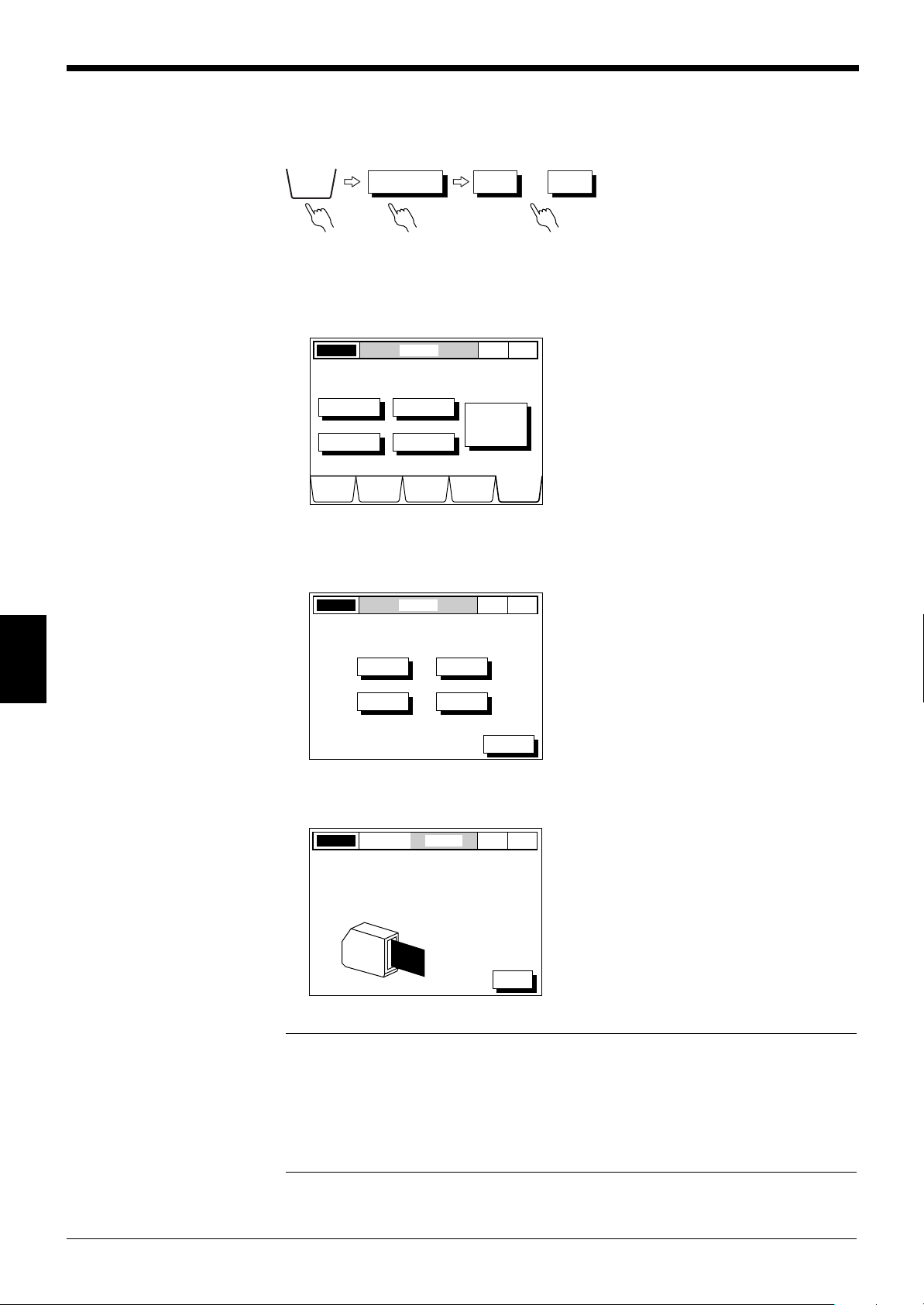
Chapter 6 Normal Mode
OPTIONS
OUTPUT OUT1 • • • OUT4
LASER ON OPTIONS
NOR
MAL
P. 1
DISPLAY
DATA
LIMIT
SETUP
PROGRAMCALIB OPTIONS
AREA
OUTPUT
INSPECT
UTILITY
Select Option to setup.
MODE
CHANGE
Normal
-> Pitch
LASER ON INSPECT
NOR
MAL
P. 1
HEAD1
HEAD2
HEAD3
HEAD4
ESC
Select Head to inspect.
INSPECTHEAD1LASER ON P. 1
BEAM INTENSITY
HEAD R
: OK
: OKOPTICAL AXIS
ESC
NOR
MAL
EE
E Inspection
EE
The scanning head can be checked for conditions such as dust on the front
surface, laser condition, and optical axis alignment.
■ Setting Procedure
1. Select the OPTIONS screen. Press the [OPTIONS] button.
2. Select the INSPECT screen. Press the [INSPECT] button.
6
3. Check the condition of the scanning head.
Press the button corresponding to the scanning head to be inspected.
When the condition of the scanning head is normal, the display is as shown
below.
60
Note 1: During the scanning head inspection, measurement is interrupted. (The
comparator output and analog output are the same as when “-----” is displayed.)
Comparator output: All outputs are OFF.
Analog output: Retained at +10 V.
Note 2: When any problem occurs with the laser diode, the message “LASER” is
displayed on the screen.
Page 67

Chapter 6 Normal Mode
INSPECTHEAD1LASER ON P. 1
BEAM INTENSITY
HEAD R
: OK
: NGOPTICAL AXIS
ESC
NOR
MAL
INSPECTHEAD1LASER ON P. 1
BEAM INTENSITY
HEAD R
: OK
: NGOPTICAL AXIS
ESC
NOR
MAL
INSPECTHEAD1LASER ON P. 1
BEAM INTENSITY
HEAD R
: OK
: NGOPTICAL AXIS
ESC
NOR
MAL
INSPECTHEAD1LASER ON P. 1
BEAM INTENSITY
HEAD R
: OK
: OKOPTICAL AXIS
ESC
NOR
MAL
INSPECTHEAD1LASER ON P. 1
BEAM INTENSITY
HEAD R
: OK
: NGOPTICAL AXIS
ESC
NOR
MAL
INSPECTHEAD1LASER ON P. 1
BEAM INTENSITY
HEAD R
: OK
: NGOPTICAL AXIS
ESC
NOR
MAL
INSPECTHEAD1LASER ON P. 1
BEAM INTENSITY
HEAD R
: OK
: NGOPTICAL AXIS
ESC
NOR
MAL
INSPECTHEAD1LASER ON P. 1
BEAM INTENSITY
HEAD R
: OK
: NGOPTICAL AXIS
ESC
NOR
MAL
INSPECTHEAD1LASER ON P. 1
BEAM INTENSITY
HEAD R
: OK
: NGOPTICAL AXIS
ESC
NOR
MAL
INSPECTHEAD1LASER ON P. 1
BEAM INTENSITY
HEAD R
: NG
: NGOPTICAL AXIS
ESC
NOR
MAL
INSPECTHEAD1LASER ON P. 1
ESC
NOR
MAL
Laser beam is tgurned off.
Optical axis cannot be checked.
Receiver Transmitter Receiver Transmitter
Receiver
Transmitter
Receiver
Transmitter
Receiver Transmitter
Receiver Transmitter
Receiver Transmitter
Receiver Transmitter
Receiver Transmitter
● Optical axis misalignment indications
Optical axis misalignment is indicated when the receiver is tilted relative to the
optical axis.
The receiver is
tilted upward.
The receiver is
tilted to the
upper right
(viewed from
the transmitter).
Normal Alignment
The transmitter
is tilted to the
right (viewed
from the
transmitter).
The optical
axis is aligned.
The receiver is
tilted to the
upper left
(viewed from
the transmitter).
The receiver is
tilted to the left
(viewed from
the transmitter).
6
No optical axis enters the receiver.
The receiver is
tilted to the
lower right
(viewed from
the
transmitter).
Laser beam is not emitted.
The receiver is
tilted
downward.
The receiver is
tilted to the
lower left
(viewed from
the transmitter).
61
Page 68

Chapter 6 Normal Mode
LASER ON OPTIONS
NOR
MAL
P. 1
DISPLAY
DATA
LIMIT
SETUP
PROGRAMCALIB OPTIONS
AREA
OUTPUT
INSPECT
UTILITY
Select Option to setup.
MODE
CHANGE
Normal
-> Pitch
LASER ON UTILITY
NOR
MAL
P. 1
AREA CHECK
INITIALIZE
ON
PANEL
mm
ONE-SCAN MODE
PROGRAM SELECT
DISPLAY UNIT
ESC
Optical axis
OPTIONS
UTILITY
FF
F One-scan Mode
FF
Data on only one of the 12 surfaces of the polygon mirror becomes effective.
(This mode negates slight changes in the optical axis caused by the polygon mirror
surface runout.) This is effective for measuring a narrow gap as shown below.
■ Setting Procedure
1. Select the OPTIONS screen.
Press the [OPTIONS] button.
6
2. Select the UTILITY screen.
Press the [UTILITY] button.
3. Set the one-scan mode.
Press the [ONE-SCAN MODE] button to turn it ON.
Every time you press this button, the display toggles between ON and OFF.
62
Page 69

Chapter 6 Normal Mode
0.3 mm or more gap width is required.
Note: The laser beam spot diameter is 0.2 mm at a distance of 80 mm from the
transmitter. For gap measurement, however, a gap width of 0.3 mm or more is
required.
When the one-scan mode is used, the averaging time1. is longer than in normal
measuring mode.
No. of averaging measurements and averaging time
when one-scan mode is ON/OFF
OFF ON Averaging time
11 10 ms
21 10 ms
41 10 ms
81 10 ms
12 1 10 ms
24 2 20 ms
48 4 40 ms
96 8 80 ms
192 16 160 ms
384 32 320 ms
768 64 640 ms
1536 128 1280 ms
3072 256 2460 ms
6144 512 5120 ms
6
1. The averaging time is not the same as mean output response time. For the
output response time, see p. 121.
63
Page 70
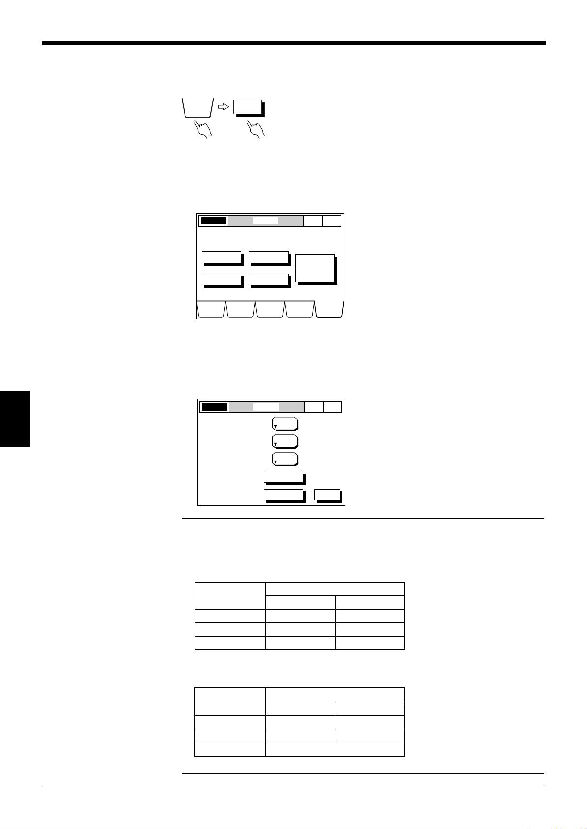
Chapter 6 Normal Mode
OPTIONS
UTILITY
LASER ON OPTIONS
NOR
MAL
P. 1
DISPLAY
DATA
LIMIT
SETUP
PROGRAMCALIB OPTIONS
AREA
OUTPUT
INSPECT
UTILITY
Select Option to setup.
MODE
CHANGE
Normal
-> Pitch
LASER ON UTILITY
NOR
MAL
P. 1
AREA CHECK
INITIALIZE
ON
PANEL
mm
ONE-SCAN MODE
PROGRAM SELECT
DISPLAY UNIT
ESC
GG
G Program Selection Method Setup
GG
The program selection method can be set to the front panel or the rear terminals.
■ Setting Procedure
1. Select the OPTIONS screen. Press the [OPTIONS] button.
2. Select the UTILITY screen. Press the [UTILITY] button.
6
3. Set the program selection method.
Press the [PROGRAM SELECT] button to select [PANEL] or [EXT].
Every time you press the button, the display toggles between [PANEL] and
[EXT].
Note 1: When the program selection method is set to [PANEL], program selection
can be performed using the front panel and the RS-232C input.
Note 2: When the program selection method is set to [EXT], program selection can
be performed using the terminal input only.
Program selection
Panel Terminal
Front panel Enabled Disabled
Terminal input Disabled Enabled
RS-232C input Enabled Disabled
64
Note 3: When the panel lock function is used, program selection is performed as
shown below.
Program selection
Panel Terminal
Front panel Disabled Disabled
Terminal input Disabled Enabled
RS-232C input Enabled Disabled
➮
For information on the panel lock function, see p. 112.
Page 71
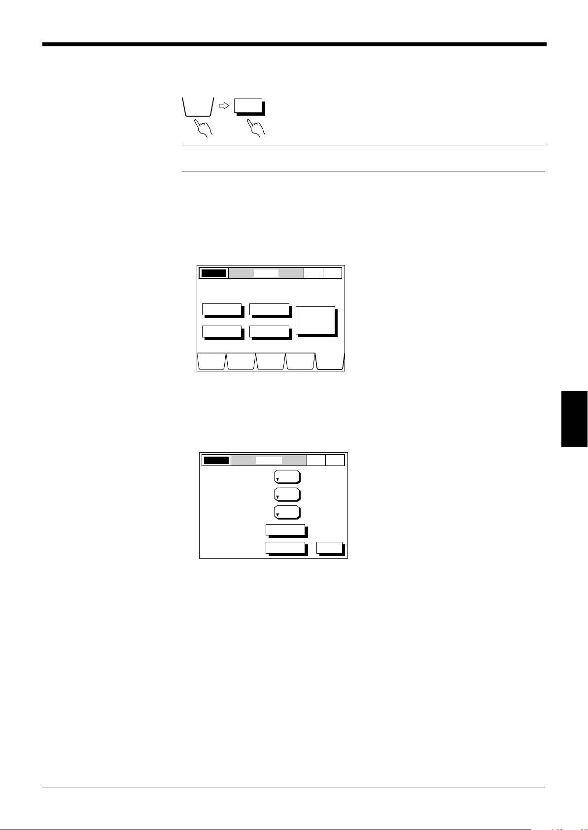
HH
OPTIONS
UTILITY
LASER ON OPTIONS
NOR
MAL
P. 1
DISPLAY
DATA
LIMIT
SETUP
PROGRAMCALIB OPTIONS
AREA
OUTPUT
INSPECT
UTILITY
Select Option to setup.
MODE
CHANGE
Normal
-> Pitch
LASER ON UTILITY
NOR
MAL
P. 1
AREA CHECK
INITIALIZE
ON
PANEL
mm
ONE-SCAN MODE
PROGRAM SELECT
DISPLAY UNIT
ESC
H Display Unit
HH
Chapter 6 Normal Mode
The measured value can be displayed in millimeters or inches.
Note: When the display units setting is changed, the preset values (tolerance
limits, etc.) of the selected program number are reset to the initial settings.
■ Setting Procedure
1. Select the OPTIONS screen.
Press the [OPTIONS] button.
2. Select the UTILITY screen.
Press the [UTILITY] button.
3. Set the display unit.
Press the [DISPLAY UNIT] button to select [mm] or [inch].
Every time you press the button, the display toggles between [mm] and [inch].
6
65
Page 72

Chapter 6 Normal Mode
LASER ON OPTIONS
NOR
MAL
P. 1
DISPLAY
DATA
LIMIT
SETUP
PROGRAMCALIB OPTIONS
AREA
OUTPUT
INSPECT
UTILITY
Select Option to setup.
MODE
CHANGE
Normal
-> Pitch
LASER ON UTILITY
NOR
MAL
P. 1
AREA CHECK
INITIALIZE
ON
PANEL
mm
ONE-SCAN MODE
PROGRAM SELECT
DISPLAY UNIT
ESC
LASER ON AREA CHECK
NOR
MAL
P. 1
OFF
ESC
SET
HEAD No.
HEAD1A1
NO. OF
EDGES
( 4 )
DIA
SEGMENT
OFF
SET
HEAD No.
HEAD1A2
NO. OF
EDGES
( 4 )
DIA
SEGMENT
SEGMENT
SEGMENT
OFF
SET
HEAD No.
HEAD1A3
NO. OF
EDGES
( 4 )
DIA
OFF
SET
HEAD No.
HEAD1A4
NO. OF
EDGES
( 4 )
DIA
II
I Area Check Function
II
When the number of edges changes during measurement, the area check function
displays the “----” error message. It also cancels the measured value by detecting
the difference from the preset total number of edges.
■ Effective Application
When dust or oil adheres to the scanning head or no target is placed in the
measuring area, the area check function prevents an abnormal measured value
from being displayed or output.
■ Setting Procedure
1. Select the OPTIONS screen.
Press the [OPTIONS] button.
2. Select the UTILITY screen.
Press the [UTILITY] button.
6
3. Press the [AREA CHECK] button.
4. Set the number of edges.
Press the [SET] button.
66
Enter a value using the numeric keys.
Press the [OFF] button to turn it ON.
Every time you press the button, the display toggles between [ON] and [OFF].
Page 73

JJ
OPTIONS
UTILITY AREA CHECK
LASER ON OPTIONS
NOR
MAL
P. 1
DISPLAY
DATA
LIMIT
SETUP
PROGRAMCALIB OPTIONS
AREA
OUTPUT
INSPECT
UTILITY
Select Option to setup.
MODE
CHANGE
Normal
-> Pitch
LASER ON UTILITY
NOR
MAL
P. 1
AREA CHECK
INITIALIZE
ON
PANEL
mm
ONE-SCAN MODE
PROGRAM SELECT
DISPLAY UNIT
ESC
LASER ON INITIALIZE
NOR
MAL
P. 1
Initialize the current settings?
YES NO
LASER ON INITIALIZE
NOR
MAL
P. 1
The current settings
will be initialized.
OK CANCEL
J Initialize
JJ
Chapter 6 Normal Mode
This function resets all settings to the initial values.
■ Setting Procedure
1. Select the OPTIONS screen.
Press the [OPTIONS] button.
2. Select the UTILITY screen.
Press the [UTILITY] button.
3. Perform initialization.
Press the [INITIALIZE] button.
➮
See p. 116 and 117.
4. Press the [YES] button.
5. Press the [OK] button.
6
67
Page 74

Chapter 6 Normal Mode
OPTIONS
MODE CHANGE
Normal
Pitch
LASER ON OPTIONS
NOR
MAL
P. 1
DISPLAY
DATA
LIMIT
SETUP
PROGRAMCALIB OPTIONS
AREA
OUTPUT
INSPECT
UTILITY
Select Option to setup.
MODE
CHANGE
Normal
-> Pitch
LASER ON MODE CHANGE
NOR
MAL
P. 1
Change the Pitch Mode?
YES NO
LASER ON MODE CHANGE
NOR
MAL
P. 1
Mode changed to Pitch.
OK CANCEL
KK
K Mode Change
KK
The measuring mode can be changed from Normal mode to Pitch mode.
■ Setting Procedure
1. Select the OPTIONS screen.
Press the [OPTIONS] button.
2. Change the measuring mode.
Press the [CHANGE MODE Normal -> Pitch] button.
6
3. Press the [YES] button.
Press the [OK] button.
68
Page 75

Chapter 7
Pitch Mode
This section describes functions and settings procedures for Pitch mode.
7.1 Pitch Mode Screens ............................................................ 70
7.2 Initial Screen ....................................................................... 71
7.3 Setting Measurement ......................................................... 72
7.4 Setting Functions ............................................................... 73
Page 76
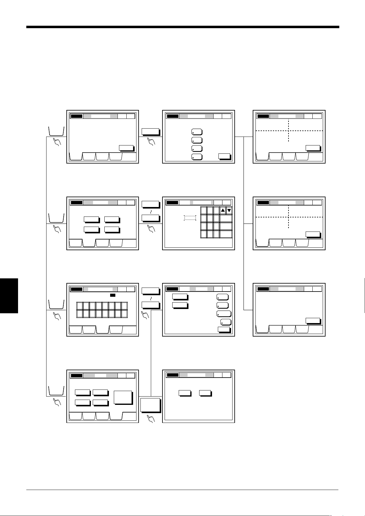
Chapter 7 Pitch Mode
LASER ON OPTIONS P. 1PITCH
DISPLAY
DATA
LIMIT
SET UP
PROGRAM OPTIONS
HEAD1
HEAD2
HEAD3
HEAD4
MODE
CHANGE
Pitch
-> Normal
MODE
CHANGE
Pitch
-> Normal
LASER ON DISPLAY DATA P. 1
PITCH
HEAD1 OK
Max 0.5010
Min
ESC
ONHEAD1
OFFHEAD2
OFFHEAD3
OFFHEAD4
Set Output to display data.
LASER ON DISPLAY SETUP
PITCH
P. 1
0.4990
SCREEN
SCREEN
HEAD1
HEAD4
DISPLAY
DATA
LIMIT
SET UP
PROGRAM OPTIONS
LASER ON DISPLAY DATA PITCH P. 1
HEAD1OKMax
Min
0.5010
0.4990
HEAD2OKMax
Min
0.6010
0.5990
HEAD3OKMax
Min
0.7020
0.6980
HEAD4OKMax
Min
0.8020
0.7980
SCREEN
DISPLAY
DATA
LIMIT
SET UP
PROGRAM OPTIONS
LASER ON DISPLAY DATA PITCH P. 1
HEAD1OKMax
Min
0.5010
0.4990
HEAD2OKMax
Min
0.6010
0.5990
HEAD3OKMax
Min
0.7020
0.6980
SCREEN
DISPLAY
DATA
LIMIT
SET UP
PROGRAM OPTIONS
DISPLAY
DATA
LIMIT
SETUP
PROGRAM
LASER ON LIMIT SETUP P. 1PITCH
DISPLAY
DATA
LIMIT
SET UP
PROGRAM OPTIONS
HEAD1
HEAD2
HEAD3
HEAD4
Select Head to set the limits.
LIMIT SETUPHEAD1LASER ON P. 1PITCH
87
5 64
2 31
0
9
ENTER
CANCEL
ESCAPE
+0.0100
1.0000
UPPER LIMIT:
REFERENCE:
LOWER LIMIT: -0.0100
HEAD1
HEAD4
LASER ON DISPLAY DATA PITCH P. 1
HEAD1
OK
Max 0.5010
Min 0.4990
HEAD2
OK
Max 0.6010
Min 0.5990
SCREEN
DISPLAY
DATA
LIMIT
SET UP
PROGRAM OPTIONS
OPTIONSHEAD1LASER ON P. 1PITCH
MASK1:
PITCH No.
NO. OF
PITCHES
MASKING
10
0
MASK2:
PITCH No.
0
MASK3:
PITCH No.
0
AVERAGE
8
DIGIT
SUPPRESS
NONE
MEASURING MODE
NORMAL
SELF-TIMING
INTERVAL (ms)
100
ESC
LASER ON SELECT PROGRAM No. P. 1PITCH
DISPLAY
DATA
LIMIT
SET UP
PROGRAM
OPTIONS
Selected program No.
1
5 87642 31
13 1615141210 119
OPTIONS
LASER ON MODE CHANGE P. 1PITCH
Change to Normal mode?
YES NO
7.1 Pitch Mode Screens
DISPLAY DATA screen
➮
See p.73.
LIMIT SETUP screen
➮
See p.75.
SELECT PROGRAM NO. screen
DISPLAY SETUP screen DISPLAY DATA screen
➮
See p.73.
➮
See p.73.
LIMIT SETUP screen DISPLAY DATA screen
➮
See p.75.
➮
See p.73.
MEASUREMENT SETUP screen DISPLAY DATA screen
7
➮
See p.76.
OPTIONS screen
➮
See p.77.
70
➮
See p.77 - 84.
MODE CHANGE screen
➮
See p.85.
➮
See p.73.
Page 77

7.2 Initial Screen
LASER ON DISPLAY DATA PITCH P. 1
HEAD1OKMax
Min
0.5010
0.4990
HEAD2OKMax
Min
0.6010
0.5990
HEAD3OKMax
Min
0.7020
0.6980
HEAD4OKMax
Min
0.8020
0.7980
SCREEN
DISPLAY
DATA
LIMIT
SETUP
PROGRAM OPTIONS
Chapter 7 Pitch Mode
Only the maximum and
minimum values of
scanning head 1 are
displayed.
Laser ON/OFF
status
To the
DISPLAY
DATA screen
To the LIMIT
SETUP
screen
Screen title
To the SELECT
PROGRAM NO.
screen
Measuring mode
Program
No.
Screen
selection
switch
To the
OPTIONS
screen
7
71
Page 78

Chapter 7 Pitch Mode
OPTIONSOUT1LASER ON P. 1PITCH
MASK1:
PITCH No.
NO. OF
PITCHES
MASKING
HEAD1 HEAD4
10
0
MASK2:
PITCH No. 0
MASK3:
PITCH No. 0
AVERAGE
8
DIGIT
SUPPRESS
NONE
MEASURING MODE
NORMAL
SELF-TIMING
INTERVAL (ms)
100
ESC
OPTIONS
7.3 Setting Measurement
When Pitch mode is selected, only one measurement can be performed with one
scanning head, unlike in Normal mode. Therefore, Pitch mode setup must be
performed for each scanning head.
■ Setting Procedure
Indicates the scanning head number
for which Pitch mode is being set.
7
Set the number of pitches.
Set the masking function.
Set the number
of averaging
measurements.
Set the digit
suppression
function.
Set the
measuring
mode.
72
Page 79

7.4 Setting Functions
DISPLAY
DATA
SCREEN
LASER ON DISPLAY SETUP P. 1
ONHEAD1
ONHEAD2
ONHEAD3
ONHEAD4
ESC
Set Output to display data.
LASER ON DISPLAY DATA PITCH
PITCH
P. 1
HEAD1OKMax
Min
0.5010
0.4990
HEAD2OKMax
Min
0.6010
0.5990
HEAD3OKMax
Min
0.7020
0.6980
HEAD4OKMax
Min
0.8020
0.7980
SCREEN
DISPLAY
DATA
LIMIT
SETUP
PROGRAM OPTIONS
LASER ON DISPLAY SETUP P. 1
ONHEAD1
OFFHEAD2
OFFHEAD3
OFFHEAD4
ESC
Set Output to display data.
LASER ON DISPLAY DATA PITCH
PITCH
P. 1
HEAD1 OK
Max 0.5010
Min 0.4990
SCREEN
DISPLAY
DATA
LIMIT
SET UP
PROGRAM OPTIONS
Switch Function Description Reference
DATA DISPLAY Screen Selection Measurement results are 72, 73
LIMIT SETUP Limit Setup Upper and lower limits can be set 75
PROGRAM Program Measurement conditions can be 76
SELECT Selection stored and retrieved as programs.
OPTIONS No. of Pitches Set the number of pitches 77
Chapter 7 Pitch Mode
displayed.
relative to the reference value for
each output.
according to the target.
Average Measurement results can be 79
averaged.
Digit suppression The number of digits after the 80
decimal point can be set.
M. Mode Three measuring modes are 81-83
provided.
Masking Set the pitch number for the 84
For each scanning head
Mode Change Normal mode or Pitch mode 85
measurement to be canceled.
can be selected.
page
1 1
1 Screen Selection Function
1 1
Using the screen selection function, set the measured value display screen (OUT1
to OUT4).
[Example 1: Four measurement results are displayed.]
[Example 2: One measurement result is displayed.]
7
73
Page 80

Chapter 7 Pitch Mode
LASER ON DISPLAY DATA PITCH P. 1
HEAD1 OK
Max 0.5010
Min 0.4990
HEAD2 OK
Max 0.6010
Min 0.5990
SCREEN
DISPLAY
DATA
LIMIT
SETUP
PROGRAM OPTIONS
LASER ON DISPLAY SETUP P. 1
ONHEAD1
ONHEAD2
ONHEAD3
ONHEAD4
ESC
Set Output to display data.
PITCH
LASER ON DISPLAY DATA PITCH P. 1
HEAD1OKMax
Min
0.5010
0.4990
HEAD2OKMax
Min
0.6010
0.5990
HEAD3OKMax
Min
0.7020
0.6980
HEAD4OKMax
Min
0.8020
0.7980
SCREEN
DISPLAY
DATA
LIMIT
SETUP
PROGRAM OPTIONS
■ Setting Procedure
1. Select the DISPLAY DATA screen.
Press the [DISPLAY DATA] button.
Press the [SCREEN] button.
2. Select the data display screen.
Press the button corresponding to the output to be displayed to turn it ON.
Press the [ESC] button.
7
3. The screen has been changed.
74
Page 81

22
HEAD1 • • • HEAD4
LIMIT
SETUP
LASER ON LIMIT SETUP P. 1PITCH
DISPLAY
DATA
LIMIT
SETUP
PROGRAM OPTIONS
HEAD1
HEAD2
HEAD3
HEAD4
Select Head to set the limits.
LIMIT SETUPHEAD1LASER ON P. 1PITCH
87
5 64
2 31
0
9
ENTER
CANCEL
ESCAPE
+0.0100
1.0000
UPPER LIMIT:
REFERENCE:
LOWER LIMIT: -0.0100
2 Limit Setup
22
Chapter 7 Pitch Mode
The reference value, upper limit, and lower limit can be set separately for each of
the four scanning heads.
■ Setting Procedure
1. Select the LIMIT SETUP screen.
Press the [LIMIT SETUP] button.
2. Set tolerance limits.
Press the button corresponding to the output for which tolerance limits are to be
set.
Set tolerance limits using the numeric keys, and press [ENTER].
Press [ESCAPE] to complete the entry.
Press [CANCEL] to cancel the entry. The value returns to the previous value.
Note: When the measured value exceeds the tolerance range, the value is displayed in reverse. The differentiation result relative to the tolerance limits is output
from the display unit and the control I/O board (optional).
When the measured value exceeds the upper limit or falls below the lower limit, the
HI1 output is turned on.
7
In PITCH mode, the Upper-Lower Limit indicates the difference from the Reference
value. If a measured value of more than 1.1000 mm is to be checked and the
Reference value is set to 1.000 mm, the Upper Limit should be +0.1000. If 0.9000
mm is to be checked, the Lower Limit should be -0.1000 mm.
75
Page 82

Chapter 7 Pitch Mode
LASER ON SELECT PROGRAM No. P. 1PITCH
DISPLAY
DATA
LIMIT
SETUP
PROGRAM
OPTIONS
Selected program No.
1
5 87642 31
13 1615141210 119
• • •
PROGRAM
1 16
33
3 Program Selection Function
33
The LS-5000 series can store all the measurement conditions as a program. Up to
16 programs can be stored and loaded easily.
■ Setting Procedure
1. Select the SELECT PROGRAM NO. Screen.
Press the [PROGRAM] button.
2. Select a program number.
Press the button corresponding to the desired program number.
7
Note: When the program selection method is set to the rear terminals, the program
number cannot be changed using the front panel.
➮
See p. 64.
76
Page 83

44
1
2
3
The number
of pitches is "3".
HEAD1
NO. OF
PITCHES
• • • HEAD4
OPTIONS
LASER ON OPTIONS P. 1PITCH
DISPLAY
DATA
LIMIT
SETUP
PROGRAM OPTIONS
HEAD1
HEAD2
HEAD3
HEAD4
MODE
CHANGE
Pitch
-> Normal
OPTIONSHEAD1LASER ON P. 1PITCH
MASK1:
PITCH No.
NO. OF
PITCHES
MASKING
10
0
MASK2:
PITCH No.
0
MASK3:
PITCH No.
0
AVERAGE
8
DIGIT
SUPPRESS
NONE
MEASURING MODE
NORMAL
SELF-TIMING
INTERVAL (ms)
100
ESC
OPTIONSHEAD1LASER ON P. 1PITCH
87
5 64
2 31
0
9
ENTER
CANCEL
ESCAPE
NO. OF
PITCHES
MASKING
10 AVERAGE
8
MASK1:
PITCH No.
0
MASK2:
PITCH No.
0
MASK3:
PITCH No.
0
4 Setting Number of Pitches
44
The number of pitches can be set up to 100, depending on the target.
Example: IC lead pitch measurement
■ Setting Procedure
1. Select the OPTIONS screen.
Press the [OPTIONS] button.
Chapter 7 Pitch Mode
2. Set the number of pitches.
Press the button corresponding to the output for which the number of pitches is
to be set.
3. Press the [NO. OF PITCHES] button.
7
4. Enter a value using the numeric keys, and press [ENTER].
Press [ESCAPE] to complete the entry.
Press [CANCEL] to cancel the entry. The value returns to the previous value.
77
Page 84

Chapter 7 Pitch Mode
Missing pin
LASER ON DISPLAY DATA PITCH P. 1
HEAD1 Err
Max - - - - - - -
Min - - - - - - -
SCREEN
DISPLAY
DATA
LIMIT
SETUP
PROGRAM OPTIONS
Note 1: Up to 100 pitches can be set.
Note 2: When the number of pitches for a target is different from the preset number
of pitches, “-----” is displayed and "Err" appears. (When the error message is
displayed, the HI3 output of the control I/O board (optional) is turned ON.)
7
78
Page 85

55
HEAD1 • • • HEAD4
OPTIONS
LASER ON OPTIONS P. 1PITCH
DISPLAY
DATA
LIMIT
SETUP
PROGRAM OPTIONS
HEAD1
HEAD2
HEAD3
HEAD4
MODE
CHANGE
Pitch
-> Normal
1
24816
OPTIONSHEAD1LASER ON P. 1PITCH
MASK1:
PITCH No.
NO. OF
PITCHES
MASKING
10
0
MASK2:
PITCH No.
0
MASK3:
PITCH No.
0
AVERAGE
8
DIGIT
SUPPRESS
NONE
MEASURING MODE
NORMAL
SELF-TIMING
INTERVAL (ms)
100
ESC
5 Average
55
Chapter 7 Pitch Mode
The number of averaging measurements can be set, according to the application,
as follows:
• Increase the number of averaging measurements to average fluctuations in
measured values to obtain stable data.
• Reduce the number of averaging measurements to increase differentiation
speed.
■ Setting Procedure
1. Select the OPTIONS screen. Press the [OPTIONS] button.
2. Set the number of averaging measurements.
Press the button corresponding to head number for which the number of
averaging measurements is to be set.
Press this button and set the number of averaging measurements.
Every time you press this button, the display changes in the following order.
7
[Relationship between No. of averaging measurements and averaging time]
No. of averaging measurements Averaging time
1 10 ms
2 20 ms
4 40 ms
8 80 ms
16 160 ms
Note: The averaging time is not the same as mean output response time. For
information on output response time, see p. 121.
79
Page 86

Chapter 7 Pitch Mode
LASER ON OPTIONS P. 1PITCH
DISPLAY
DATA
LIMIT
SETUP
PROGRAM OPTIONS
HEAD1
HEAD2
HEAD3
HEAD4
MODE
CHANGE
Pitch
-> Normal
NONE
1234
OPTIONSHEAD1LASER ON P. 1PITCH
MASK1:
PITCH No.
NO. OF
PITCHES
MASKING
10
0
MASK2:
PITCH No.
0
MASK3:
PITCH No.
0
AVERAGE
8
DIGIT
SUPPRESS
NONE
MEASURING MODE
NORMAL
SELF-TIMING
INTERVAL (ms)
100
ESC
HEAD1 • • • HEAD4
OPTIONS
NONE
1
2
3
4
66
6 Digit Suppression Function
66
The number of digits after the decimal point can be suppressed as desired.
■ Setting Procedure
1. Select the OPTIONS screen.
Press the [OPTIONS] button.
2. Set the number of digits.
Press the button corresponding to the scanning heads for which the number of
digits is to be set.
7
Press this button to select the number of digits.
Every time you press this button, the display changes in the following order.
Note: The relationship between each switch setting and the displayed digits is as
follows:
Example
(Displays 5 digits after the decimal point: 10.00000 mm/1.000000 inch)
(Displays 4 digits after the decimal point: 10.0000 mm/1.00000 inch)
(Displays 3 digits after the decimal point: 10.000 mm/1.0000 inch)
(Displays 2 digits after the decimal point: 10.00 mm/1.000 inch)
(Displays 1 digit after the decimal point: 10.0 mm/1.00 inch)
80
Page 87

77
LASER ON OPTIONS P. 1PITCH
DISPLAY
DATA
LIMIT
SETUP
PROGRAM OPTIONS
HEAD1
HEAD2
HEAD3
HEAD4
MODE
CHANGE
Pitch
-> Normal
NORMAL SAMPLE
SELF-TIMING
OPTIONSHEAD1LASER ON P. 1PITCH
MASK1:
PITCH No.
NO. OF
PITCHES
MASKING
10
0
MASK2:
PITCH No.
0
MASK3:
PITCH No.
0
AVERAGE
8
DIGIT
SUPPRESS
NONE
MEASURING MODE
NORMAL
SELF-TIMING
INTERVAL (ms)
100
ESC
100 200 500 1000 10 50
OPTIONSHEAD1LASER ON P. 1PITCH
MASK1:
PITCH No.
NO. OF
PITCHES
MASKING
10
0
MASK2:
PITCH No.
0
MASK3:
PITCH No.
0
AVERAGE
8
DIGIT
SUPPRESS
NONE
MEASURING MODE
NORMAL
SELF-TIMING
INTERVAL (ms)
100
ESC
7 Measuring Mode
77
Chapter 7 Pitch Mode
The LS-5000 series provides the following three measuring modes.
Mode Description
Normal The measured value and differentiation results are displayed/output
at any time.
Sample hold The instantaneous value at a specified time is measured.
Self-timing Automatic measurement without using external synchronous input.
■ Setting Procedure
1. Select the OPTIONS screen. Press the [OPTIONS] button.
2. Set the measuring mode.
Press the button corresponding to the head for which the measuring mode is to
be set.
Press this button to select the measuring mode.
Every time you press this button, the display changes in the following order.
[When self-timing mode is selected]
3. Set the self-timing interval.
Every time you press this button, the display changes in the following order.
7
Note: The self-timing interval can be set only when self-timing mode is selected.
81
Page 88

Chapter 7 Pitch Mode
OK OUT
ON
Upper limit
Max. Value
Min. value
Lower limit
OFF
NG OUT
Synchronous input retains the
output status until it turns off.
ON
OFF
Err
Synchronous
input
ON
OFF
ON
OFF
OK
ON
OFF
NG
ON
OFF
Err
ON
OFF
ON
OFF
Upper limit
Max. Value
Min. value
Lower limit
Synchronous
input
● Normal mode
The maximum and minimum values of the measured pitch and the differentiation
result can be displayed/output at any time.
Timing Diagram
7
• The output when the synchronous input is turned ON is retained.
• When the reset input is turned ON while the synchronous input is ON, “—” is
displayed and the Err output is turned ON.
● Sample hold mode
The instantaneous value at a specified time can be measured.
Timing Diagram
82
• The value when the synchronous input is turned ON is retained.
• When the reset input is turned ON, “—” is displayed and the Err output is turned
ON.
Page 89
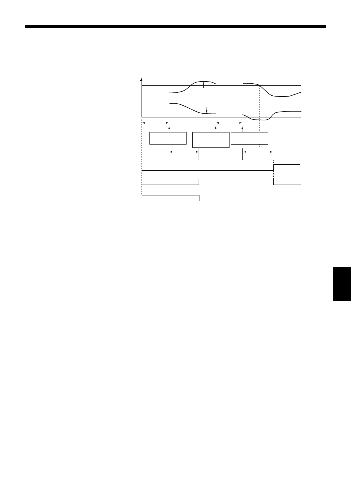
Chapter 7 Pitch Mode
OK
ON
OFF
NG
ON
OFF
OFF
Err
ON
No target
Target enters the
measuring area
No target
Preset
self-timing
interval
Preset
self-timing
interval
Upper limit
Max. value
Min. value
Lower limit
Target enters the
measuring area
Target goes out of
the measuring
area
● Self-timing hold mode
Measurement can be automatically performed according to the internal synchronous signal.
Timing Diagram
• When the self-timing period has passed after a target is placed in the measuring
area, the measured value is retained.
• The previous value is retained until the self-timing period has passed after the
next target is placed in the measuring area.
• If the number of pitches of an actual target is different from the preset number of
pitches, self-timing mode is not activated even when the target is placed in the
measuring area.
7
83
Page 90

Chapter 7 Pitch Mode
1 13
Pitches to be canceled
Scanning direction
Optical
axis
HEAD1 • • • HEAD4
OPTIONS
LASER ON OPTIONS P. 1PITCH
DISPLAY
DATA
LIMIT
SETUP
PROGRAM OPTIONS
HEAD1
HEAD2
HEAD3
HEAD4
MODE
CHANGE
Pitch
-> Normal
OPTIONSHEAD1LASER ON P. 1PITCH
MASK1:
PITCH No.
NO. OF
PITCHES
MASKING
10
0
MASK2:
PITCH No.
0
MASK3:
PITCH No.
0
AVERAGE
8
DIGIT
SUPPRESS
NONE
MEASURING MODE
NORMAL
SELF-TIMING
INTERVAL (ms)
100
ESC
OPTIONSHEAD1LASER ON P. 1PITCH
87
5 64
2 31
0
9
ENTER
CANCEL
ESCAPE
NO. OF
PITCHES
MASKING
10 AVERAGE
8
MASK1:
PITCH No.
0
MASK2:
PITCH No.
0
MASK3:
PITCH No.
0
88
8 Masking
88
Up to three pitches can be excluded from measurement, based on the application,
as shown below.
If pitch (1) and pitch (13) are included in the measurement of connector lead
pitches as shown on the right, the maximum value becomes larger than the actual
value. The masking function is useful to cancel these unnecessary part in such a
case.
■ Setting Procedure
1. Select the OPTIONS screen. Press the [OPTIONS] button.
2. Set the masking function.
Press the button corresponding to the output for which the masking function is
to be set.
7
84
3. Press the [MASKING] button.
In this example, set the No. of Pitches to 13.
Enter the pitch number to be canceled using the numeric keys, and press
[ENTER]. Press [ESCAPE] to complete the entry. Press [CANCEL] to cancel
the entry. The value returns to the previous value.
In this example, set MASK1 to 1 and MASK2 to 13.
Note 1: Pitch number is counted from Pitch 1 in the scanning direction (from the top of the scanning
head to the bottom).
Note 2: When the total number of pitches changes (i.e. due to lead breakage), the control I/O board’s
HI3 output is turned ON which indicates an "Error with No. of Pitches”. (Except for the self-timing mode)
Page 91

99
LASER ON OPTIONS P. 1PITCH
DISPLAY
DATA
LIMIT
SETUP
PROGRAM OPTIONS
HEAD1
HEAD2
HEAD3
HEAD4
MODE
CHANGE
Pitch
-> Normal
LASER ON MODE CHANGE P. 1PITCH
Change to Normal mode?
YES NO
LASER ON MODE CHANGE P. 1PITCH
Mode changed to Normal.
OK CANCEL
OPTIONS
MODE CHANGE
Pitch
Normal
9 Mode Change
99
Chapter 7 Pitch Mode
The measuring mode can be changed from Pitch mode to Normal mode.
■ Setting Procedure
1. Select the OPTIONS screen.
Press the [OPTIONS] button.
2. Change the measuring mode from Pitch mode to Normal mode.
Press the [MODE CHANGE Pitch ➞ Normal] button.
3. Press the [YES] button.
4. Press the [OK] button.
7
85
Page 92

Chapter 7 Pitch Mode
7
86
Page 93

Chapter 8
RS-232C I/O
8.1 RS-232C Communication Protocol ...................................88
8.2 Remote Control Function ................................................... 90
8.3 Command List ..................................................................... 97
Page 94

Chapter 8 RS-232C I/O
1 2 3 456
3
5
4
2
3
4
6
7
8
5
SD
RD
SG
SD
RD
RS
CS
DR
ER
SG
LS PC
RJ11 modular
connector
9 pin D-sub
connector
3
5
4
2
3
4
5
6
20
7
SD
RD
SG
SD
RD
RS
CS
DR
ER
SG
LS PC
RJ11 modular
connector
25 pin D-sub
connector
1 2 3 4
ON
OFF
ON
OFF
STX +ETX
C
R
DIP switch 2
DIP switch
8.1 RS-232C Communication Protocol
Using the RS-232C interface, the LS-5000 series can communicate with a personal
computer. Data transmission and setting changes can be remotely controlled.
■ Pin Assignment
Pin No. Signal code Description Direction
1— No connection —
2— No connection —
3 SD (TXD) Inputs data from Input
4 SG (GND) Signal ground —
5 RD (RXD) Outputs measured Output
6— No connection —
Example of Connections
of signal
external equipment
value data
8
Do not connect terminals (1), (2) and (6).
■ Communication Protocol
Conforming to EIA RS-232C
These settings can be changed by adjusting DIP switch 2.
DIP switch 2 setting OFF ON
Duplex Full
Synchronization Start-stop
Data format ASCII
Data length 8
Stop bit length 1
Parity check None Even
Baud rate 9600
Delimiter CR STX + ETX
Applicable Personal computer, KV series (KV mode)
external equipment KV-300 with KV-L2
(Non procedure mode)
When DIP switch 2 is set to ON and “STX + ETX” is selected, OUT1’s measured
value is output continuously.
■ Setting Delimiter
88
Page 95

■ Examples of Connections
OP-26401 + OP-96368
(D-sub 9-pin connector + cable)
Personal computer
Straight cable
KV-10/16/24/40/80
KV-300 Series*
Cross cable OP-96607
Straight cable
OP-96368 (cable) + OP96369
(D-sub 25-pin connector)
AC
power supply
KV-U4
CPU
KV-300
Serial Interface
module KV-L2
• Connection with a personal computer
Delimiter: CR
• Connection with the KV series
Chapter 8 RS-232C I/O
Data format (Delimiter: STX + ETX)
The displayed value is output continuously.
* KV-300 series is not available in European area.
8
89
Page 96

Chapter 8 RS-232C I/O
LS-5000 series
During
measurement
During
measurement
Sends the measured
value once
Personal computer
Sends [M] [1] [CR]
End
Waiting to
receive data
8.2 Remote Control Function
You can control the LS-5000 series remotely by sending an ASCII command from
external equipment, such as a personal computer.
Character codes corresponding to the ASCII command can be used for remote
control.
Measured Value Output
RS-232C command list I
Function command received
Output of
measured value
1. Upper line: Character code, Lower line: ASCII code (Hex)
1.
[M] [#] [CR] Send a measured value once.
4DH#0DH
[N] [#] [CR] Send a measured value continuously.
4EH#0DH
[O] [CR] Stop continuous transmission of
4FH 0DH meas ured value.
Description
8
Note 1: "#" is a character code between 0 and 4, or the ASCII code corresponding
to the character code.
0: Outputs data from all output numbers.
1 to 4: Outputs data from the specified output number (OUT1 to OUT4).
Note 2: When the ASCII (character) command given in command list I is received,
the measured value is sent either once or continuously.
■ Operating Procedure
Example: Send the measured value from OUT No. 1 once.
90
Page 97

Chapter 8 RS-232C I/O
LS-5000 series
During
measurement
Sends the measured
value continuously
Stops the continuous
data transmission
Personal computer
Sends [N] [2] [CR]
Sends [O] [CR]
End
Receives data
continuously
During continuous
data transmission
First data Second data Third data 4th data 5th data 6th data 7th data 8th data 9th data 10th data
123 . 45670CR
(Displayed value: 123.45670)
–SP0.98765CR
(Displayed value:-0.98765)
First data Second data Third data 4th data 5th data 6th data 7th data 8th data 9th data 10th data
11th data 12th data 13th data 14th data 15th data 16th data 17th data 18th data 19th data 20th data
SP SP 1.23456 ,
SP SP 0.98765C
R
(Displayed value: Max: 1.23450, Min.: 0.98765)
Example: Send the measured value from OUT No. 2 continuously.
Note 1: When the LS-5000 series receives the “N” (continuous output) command in
either peak hold, bottom hold, difference hold, sample hold or self-timing mode, the
LS-5000 series sends the measured value once every time the synchronous input
is turned on (the measured value is confirmed).
Note 2: When the LS-5000 series receives the “N” (continuous output) command in
either normal, auto peak, auto bottom or auto difference hold mode, the LS-5000
series continuously sends the measured value.
■ Data format
• Received Command: [M] [1] [CR]
• Transmitted data
In Normal mode
In Pitch mode
8
91
Page 98

Chapter 8 RS-232C I/O
First data Second data Third data 4th data 5th data 6th data 7th data 8th data 9th data 10th data
11th data 12th data 13th data 14th data 15th data 16th data 17th data 18th data 19th data 20th data
123 . 45670 ,
–SP0 . 98765 ,
21th data 22th data 23th data 24th data 25th data 26th data 27th data 28th data 29th data 30th data
SP SP 1.23455 ,
31th data 32th data 33th data 34th data 35th data 36th data 37th data 38th data 39th data 40th data
–98 . 76540C
R
(Displayed value: OUT1: 123.45670, OUT2: -0.98765,
OUT3: 1.23455, OUT4: -98.76540)
First data Second data Third data 4th data 5th data 6th data 7th data 8th data 9th data 10th data
11th data 12th data 13th data 14th data 15th data 16th data 17th data 18th data 19th data 20th data
SP SP 1.23400 ,
SP SP 1.23000 ,
21th data 22th data 23th data 24th data 25th data 26th data 27th data 28th data 29th data 30th data
SP 10 . 56785 ,
31th data 32th data 33th data 34th data 35th data 36th data 37th data 38th data 39th data 40th data
SP 10 . 55785 ,
41th data 42th data 43th data 44th data 45th data 46th data 47th data 48th data 49th data 50th data
SP SP 2.34560 ,
51th data 52th data 53th data 54th data 55th data 56th data 57th data 58th data 59th data 60th data
SP SP 2.45670 ,
61th data 62th data 63th data 64th data 65th data 66th data 67th data 68th data 69th data 70th data
SP SP 0.34560 ,
71th data 72th data 73th data 74th data 75th data 76th data 77th data 78th data 79th data 80th data
SP SP 0.23455CR
(Displayed value: OUT1 Max.: 1.23400, Min.: 1.23000, OUT2 Max.: 10.56785,
Min.: 10.55785, OUT3 Max.: 2.34560, Min.: 2.45670, OUT4 Max.: 0.34560, Min. 0.23455)
• Received Command: [M] [0] [CR]
• Transmitted data
In Normal mode
In Pitch mode
8
92
Page 99

Control Command 1
Chapter 8 RS-232C I/O
Transmitted data for each display is as follows:
Example
Display status Normal mode Pitch mode
OUT1 123.45670 Max.: 999.99995
Min.: -99.99995
OUT2 -99.99995 Max.: - - -.- - - - -
Min.: - - -.- - - - -
OUT3 - - -.- - - - - Max.: - - -.- - - - - (No setting)
Min.: - - -.- - - - - (No setting)
OUT4 999.99995 Max.: 0.00005
Min.: -0.00005
Received command Transmitted data
[M] [1] [CR] 123.45670 999.99995
-99.99995
[M] [0] [CR] 123.45670 (OUT1) 999.99995 (OUT1 Max.)
-99.99995 (OUT2) -99.99995 (OUT1 Min.)
- - -.- - - - - (OUT3) - - -.- - - - - (OUT2 Max.)
999.9995 (OUT4) - - -.- - - - - (OUT2 Min.)
- - -.- - - - - (OUT3 Max.)
- - -.- - - - - (OUT3 Min.)
0.00005 (OUT4 Max.)
-0.00005 (OUT4 Min.)
Command list II
Function Command received
Timing [T] [#] [CR] Turns ON the synchronous input
54H#0DH
[U] [#] [CR] Turns OFF the synchronous input
55H#0DH
Reset [Q] [#] [CR] Reset input
51H#0DH
Auto-zero [V] [#] [CR] Auto-zero input
56H#0DH
[W] [#] [CR] Resets the auto-zero input
57H#0DH
1.
Description
1. Upper line: Character code, Lower line: ASCII code
Note 1: "#" is a character code between 0 and 4, or the ASCII code corresponding
to the character code.
0: Outputs data from all output numbers.
1 to 4: Outputs data from the specified output number (OUT1 to OUT4).
Note 2: When the LS-5000 series receives the ASCII (character) code given in
code list II, it performs the specified operation.
8
93
Page 100

Chapter 8 RS-232C I/O
LS-5000 series
During
measurement
During
measurement
Synchronous input for
OUT1 is turned ON
Personal computer
Sends [T] [1] [CR]
End
■ Operating Procedure
Example: Turn ON the synchronous input.
Note 1: The operating procedure for functions other than “synchronous input: ON”
is similar to the above.
Note 2: The timing, reset and auto-zero terminal input, and the RS-232C command
input can be simultaneously used.
Control Command 2
8
Command list III
Function Command received
Program No. [P] [#] [#] [CR] Program number is changed
Selection 50H##0DH
1.
Description
1. Upper line: Character code, Lower line: ASCII code
Note 1: # is a character code between 1 and 16, or the ASCII code corresponding
to the character code.
1 to 16: The program number can be changed to a number between 1 and 16.
Note 2: When the LS-5000 series receives the ASCII (character) code given in
code list III, it performs the specified operation.
94
 Loading...