

Page 1

Instruction
Manual
Laser Scan Micrometer
96M10280
LS-3100(W) Series
Page 2
S
AFETY
P
RECAUTIONS
This manual describes how to install the LS-3100(W) Series as well as its
operating procedures and precautions. Please read this manual carefully to
get the best from your LS-3100(W) Series.
Symbols
General Pecautions
The following symbols alert you to important messages. Be sure to read
these messages carefully.
WARNING
CAUTION
Note
• At startup and during operation, be sure to monitor the functions and
performance of the LS-3100(W) series.
• We recommend that you take substantial safety measures to avoid any
damage in the event a problem occurs.
• Do not open or modify the LS-3100(W) series or use it in any way other
than described in the specifications.
• When the LS-3100(W) series is used in combination with other instruments, functions and performance may be degraded, depending on
operating conditions and the surrounding environment.
Failure to follow instructions may lead to injury.
(electric shock, burn, etc.)
Failure to follow instructions may lead to product
damage.
Provides additional information on proper operation.
• Do not use the LS-3100(W) series for the purpose of protecting the
human body.
■ Best Management Practice for Perchlorate Materials — California
only
When you sell, manufacture and/or waste the products containing
perchlorate material in California, the following statement must appear on
the exterior of all outer shipping packages and on consumer packages,
based on California Code of Regulations.
“Perchlorate Material – special handling may apply, See
www.dtsc.ca.gov/hazardouswaste/perchlorate.”
Note: Alternative option is to indicate this statement on your MSDS or
manual accompanying with each product.
This product includes a CR coin type cell containing perchlorate material. If
you ship this product (or your product including this product) to California,
you must ensure to comply with this regulation.
Page 3

Unpacking
Check that the following items are included in your LS system package.
• Controller ....................................................................................... 1
• Scanning head ............................................................................... 1
• Laser beam cover (attached to scanning head) ............................ 1
• Connection cable ........................................................................... 3
• Power cable ................................................................................... 1
• Power switch key ........................................................................... 2
• Instruction manual ......................................................................... 1
• Laser beam axis alignment tool ..................................................... 1
1. Or number purchased.
2. LS-3033, 3060 only. (Not provided with LS-3033 SO)
WARRANTIES AND DISCLAIMERS
See page 97.
1.
1.
1.
1, 2.
96M10280
Page 4

CONTENTS
Chapter 1 Laser Safety Precautions 1
1-1. Classification ............................................................................................... 1
1-2. Warning Labels ...........................................................................................1
1-3. Label Location ............................................................................................. 2
1-4. Safety Consideration ................................................................................... 2
1-5. Safety Features Provided with the LS-3100 Series .................................... 3
1-6. Preparation for Operation ...........................................................................4
1-7. Connecting 2 Scanning Heads ...................................................................6
Chapter 2 Trial Operation 7
Chapter 3
Chapter 3 Quick Setup Procedures 8
3-1. Common Settings .......................................................................................9
Setting the Number of Measurements for Averaging ............................9
Tolerance Settings ..............................................................................10
3-2. Measurement Procedures ......................................................................... 10
Outer Diameter Measurements........................................................... 10
Gap Measurement 1 ...........................................................................11
Gap Measurement 2 ...........................................................................11
Measuring Roundness ........................................................................12
Measuring Eccentricity ........................................................................12
Measuring Target Displacement within the Measuring Range ........... 13
Measuring Edge Movement ................................................................13
3-3. Using LS-3100D(W) Controller with 2 Scanning Heads ...........................14
Chapter 4 Functions and Controls 15
4-1. Part Names ...............................................................................................15
Controller ..................................................................................................15
Scanning Heads ........................................................................................ 16
4-2. Indicators and Displays ............................................................................. 18
4-3. Panel Keys ................................................................................................ 19
Numeric Keys ............................................................................................ 19
SET Key .................................................................................................... 19
CLR Key .................................................................................................... 19
ENT Key .................................................................................................... 20
UP/DOWN Key .........................................................................................20
ZERO (Auto-Zero) Key .............................................................................20
HOLD Key ................................................................................................. 20
Page 5

AVE Key .................................................................................................... 21
Averaging Methods ........................................................................ 21
PRM Selector Key ..................................................................................... 22
Analog Voltage Range ................................................................... 22
LIMIT ...................................................................................................23
Tolerance Limits and Comparator Output ...................................... 24
DIGIT SUPPRESS ..............................................................................26
HOLD ..................................................................................................27
BAUD RATE ....................................................................................... 27
UNIT.................................................................................................... 27
BUZZER.............................................................................................. 28
HEAD2 ................................................................................................28
POSITION CHECK (Model: LS-3033/3060 only) ................................28
LIMIT (tolerance limits for 3-step differentiation) Key ...............................29
SEG (segment) Key ..................................................................................30
FNC (function) Key ...................................................................................32
Segment Selector ............................................................................... 32
Segment Check .................................................................................. 35
Output Channel ...................................................................................37
MODE, OFFSET, and LIMIT for CH2 ................................................. 39
MODE Key ................................................................................................40
CAL (calibration) Key ................................................................................41
DISP (subdisplay) Key ..............................................................................43
OFS (offset) Key ....................................................................................... 43
PROG (program) Key ...............................................................................45
Storing (SAVE) Settings...................................................................... 45
Retrieving (LOAD) Settings................................................................. 46
Table of I/O Terminals ........................................................................ 47
Analog Voltage Output ................................................................... 47
Comparator Output ........................................................................47
Program Selector Input Terminals ......................................................48
AUTO ZERO Terminals ......................................................................48
HOLD Terminal ...................................................................................48
Laser Emission Control Input Terminal ...............................................48
4-4. I/O Terminal .............................................................................................. 49
RS-232C I/O Terminal ..............................................................................49
36-pin Connector (Control I/O) .................................................................. 62
Input Signal .........................................................................................63
Output Signal ......................................................................................63
Functions of Terminal Blocks .................................................................... 63
Analog Voltage Output Terminals .......................................................63
Control Input Terminals....................................................................... 64
Control Output Terminals ....................................................................64
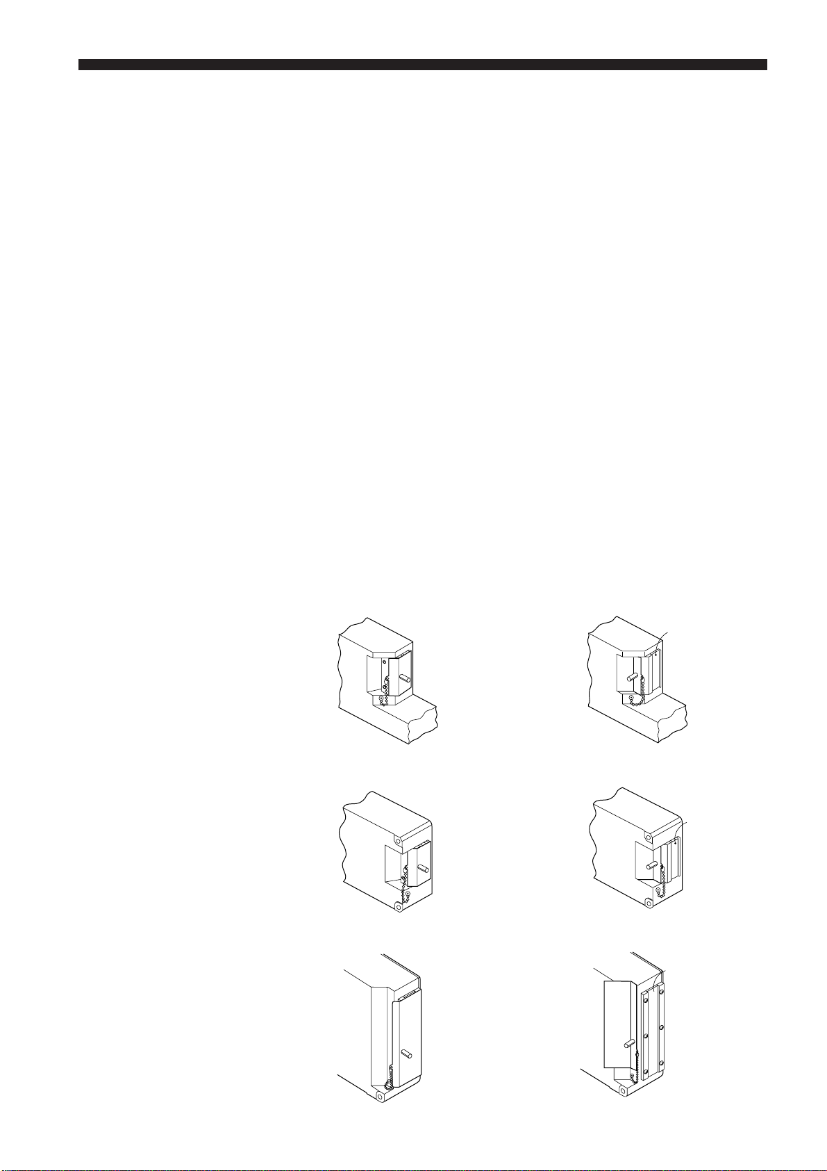
Chapter 5 Mounting Scanning Head 65
5-1. Alignment of Optical Axis (LS-3060 only) .................................................65
Allowance for Aligning Transmitter and Receiver ..................................... 65
5-2. Checking Alignment of Optical Axis (LS-3033 only) .................................66
Error Messages (For Models LS-3060 and LS-3033) ...............................67
Chapter 6 Optional Interface Boards 68
6-1. BCD Output ............................................................................................... 68
6-2. GP-IB Interface I/O ...................................................................................70
Page 6

Chapter 7 Hints on Correct Use 76
Chapter 8 Error Messages 78
H-Err .................................................................................................................. 78
P-Err .................................................................................................................. 78
CALIB ERROR .................................................................................................. 78
Chapter 9 Troubleshooting Guide 80
Troubleshooting Guide ...................................................................................... 80
Appendices 83
Appendix A Operating Principle ....................................................................... 83
Appendix B Characteristics ..............................................................................84
Measuring Area vs. Accuracy ................................................................... 84
Temperature Characteristics (Typical) ...................................................... 85
Appendix C Specifications................................................................................86
Controller ..................................................................................................86
Scanning Head .........................................................................................87
Appendix D Dimensions ................................................................................... 88
Appendix E Quick Reference Table .................................................................89
Modes (Functions) and Key Operations ...................................................89
Appendix F Key Flowcharts .............................................................................91
PRM (Parameter) ...................................................................................... 91
AVE (Average) ..........................................................................................92
SEG (Segment) ......................................................................................... 93
FNC (Function) .........................................................................................94
DISP (Display) ..........................................................................................95
MODE ....................................................................................................... 95
PROG (Program) ...................................................................................... 96
OFS (Offset) .............................................................................................. 96
LIMIT .......................................................................................................96
CAL (Calibration) ......................................................................................96
WARRANTIES AND DISCLAIMERS 97
Page 7
CHAPTER 1
AVOID EXPOSURE
LASER RADIATION
IS EMITTED FROM
THIS APERTURE.
CAUTION-Laser radiation
when open.
DO NOT STARE
INTO BEAM.
LASER SAFETY PRECAUTIONS
1-1. Classification
Laser
FDA (CDRH) 21CFR
Class
Part 1040.10
IEC60825-1 Class 1
DIN EN 60825-1 Class 1
1-2. Warning Labels
1) Warning label
FDA Class II
CAUTION
LASER RADIATION-DO NOT
STARE INTO BEAM
SEMICONDUCTOR LASER 670nm
MAXIMUM OUTPUT 0.5mW
CLASS II LASER PRODUCT
LS-3034 LS-3033 LS-3032 LS-3033 LS-3036 LS-3060
SO(8073)
Class I Class II
2) Aperture label
FDA Class II
AVOID EXPOSURE
LASER RADIATION
IS EMITTED FROM
THIS APERTURE.
CAUTION-Laser radiation
when open.
DO NOT STARE
INTO BEAM.
1
Page 8
CHAPTER 1 Preparation for Measurement
CAUTION
AVOID EXPOSURE
LASER RADIATION
IS EMITTED FROM
THIS APERTURE.
CAUTION-Laser radiation
when open.
DO NOT STARE
INTO BEAM.
AVOID EXPOSURE
1-3. Label Location
1-4 Safety Consideration
CAUTION
LASER RADIATION-DO NOT
STARE INTO BEAM
SEMICONDUCTOR LASER 670nm
MAXIMUM OUTPUT 0.5mW
CLASS II LASER PRODUCT
1) 2)
AVOID EXPOSURE
LASER RADIATION
IS EMITTED FROM
THIS APERTURE.
CAUTION-Laser radiation
when open.
DO NOT STARE
INTO BEAM.
: Aperture
CAUTION
WARNING
Use of controls or adjustments or the performance of procedures other than
those specified herein may result in hazardous radiation exposure.
The possible health hazard is in exposing the eyes to the laser beam.
Damage to the eyes can occur if the operator stares directly into the beam.
Do not look directly at the laser beam.
Follow the safety precautions below to ensure operator safety:
• Operate the LS-3100(W) series only according to the procedures
described in this instruction manual.
Otherwise, injury may occur due to exposure to the laser beam.
• Do not disassemble the sensor head.
Laser emission from the LS-3100(W) series is not automatically stopped if
the sensor head is disassembled. If you disassemble the sensor head for
inspection or repair, you may be exposed to the laser beam. If the LS3100(W) series malfunctions, contact KEYENCE immediately.
• Do not look directly at the laser beam.
Looking directly at the laser beam may result in serious eye injury.
• Protective enclosure
We recommend that you install a protective enclosure around the sensor
head to prevent any person from getting near the sensor head during
operation.
• Protective goggles
We recommend that you wear protective goggles when using the LS3100(W) series.
2
Page 9
CHAPTER 1 Preparation for Measurement
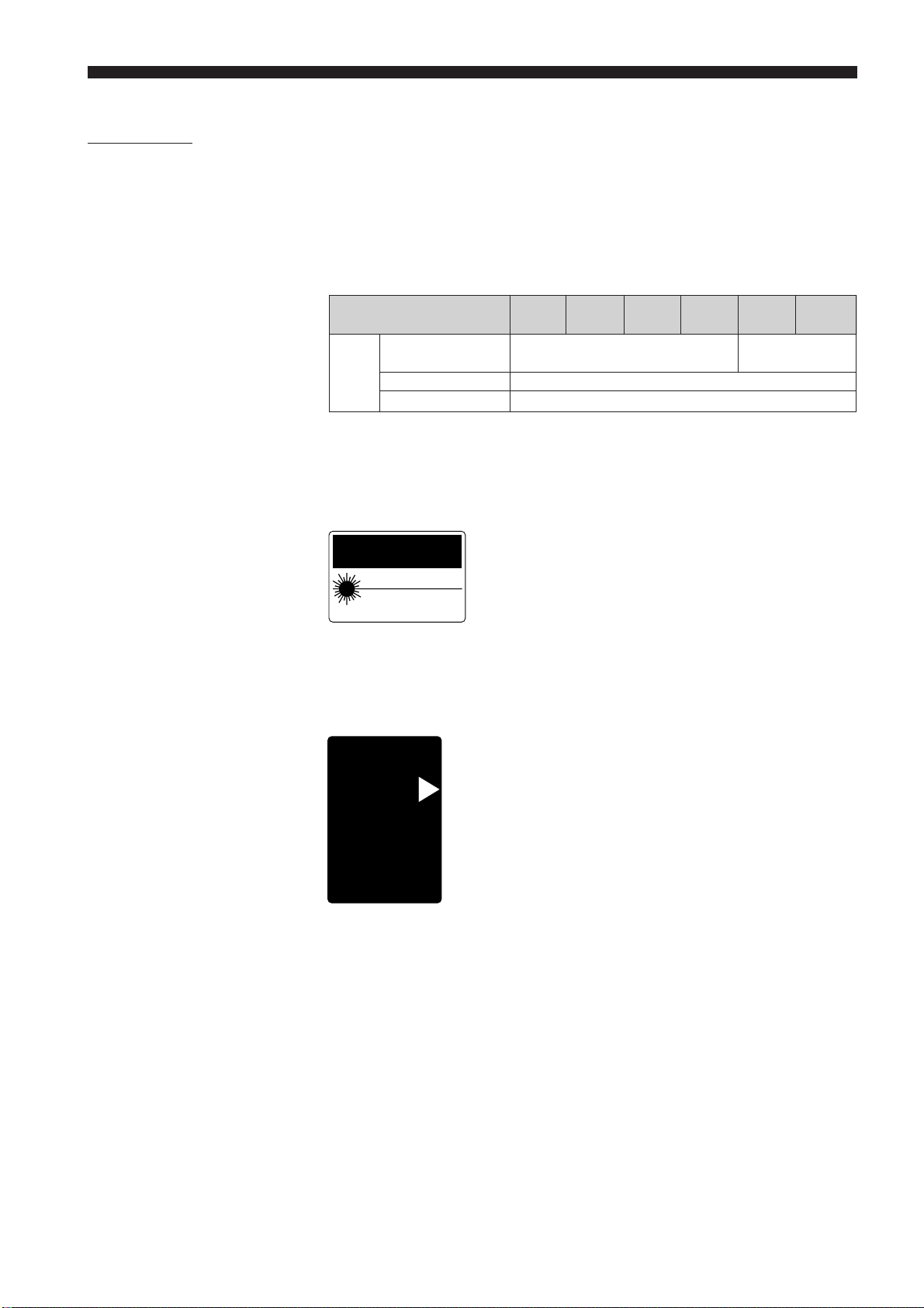
1-5 Safety Features Provided with the LS-3100(W) Series
The LS-3100(W) series has the following safety features:
■ Laser ON alarm LED
Both the sensor head and the controller panel have a visible LED that lights
when laser is ready to be and is being emitted.
LEDs can be checked to see if they are lit even when you are wearing laser
protective glasses.
■ Delay of laser beam emission
To prevent an operator from being exposed to the laser beam, the laser
beam is emitted three seconds after the laser ON alarm LED lights.
■ Laser emission remote control input connector
The laser emission control connector is located on the rear panel of the
control unit. The laser can be turned on or off by a remote control signal
through this connector.
■ Key-operated power switch
The controller power switch can be locked using the attached key.
When the LS-3100(W) controller is OFF, the key can be removed.
■ Laser beam shield
The sensor head transmitter comes with a laser beam shield.
Cover is closed. Cover is open.
LS-3032/3034/3036LS-3032/3034/3036
LS-3033/3033SO(8073) LS-3033/3033SO(8073)
Laser emission
Laser emission
LS-3060LS-3060
Laser emission
3
Page 10
CHAPTER 1 Preparation for Measurement
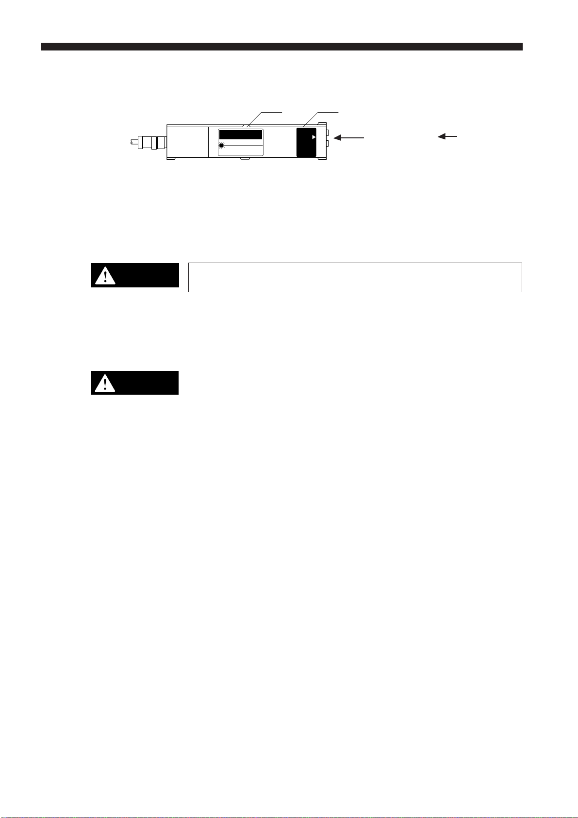
1-6. Preparation for Operation
CAUTION
CAUTION
• Do not mount the scanning head to the place where a certain level of
electrical noise is applied or transferred. Isolate the scanning head if
electrical noise may be occured. Otherwise, laser diode may deteriorate
or become damaged.
• Although the LS controller has been thoroughly inspected before shipment, we kindly request that you check it upon purchase for any damage.
Contact the nearest KEYENCE distributor if your LS controller is damaged
in any way.
• Precision components are incorporated in the scanning head, therefore be
sure not to subject it to shocks.
• The scanning head has been precision set before shipment. Always keep
the casing closed to maintain the head's setting.
• The LS controller can operate normally at 0 to 45°C (32 to 113°F) [0 to
40°C (32 to 104°F) for LS-3036/3060] with no freezing and 35 to 85%RH
without condensation. Operation outside these ranges may result in
malfunction.
Do not connect or disconnect any cables while the power is ON. Otherwise,
the laser diode may deteriorate and/or may be damaged.
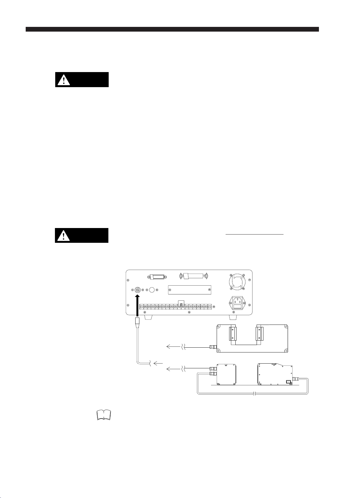
Note
1. Connect the controller to the scanning head and the transmitter and
receiver using the supplied cables.
LS-3032, LS-3034, LS-3036
LS-3033, LS-3033 SO, LS-3060
The LS-3101(W) can be used with LS-3032, 3033, 3036 and 3060.
4
Page 11
CHAPTER 1 Preparation for Measurement
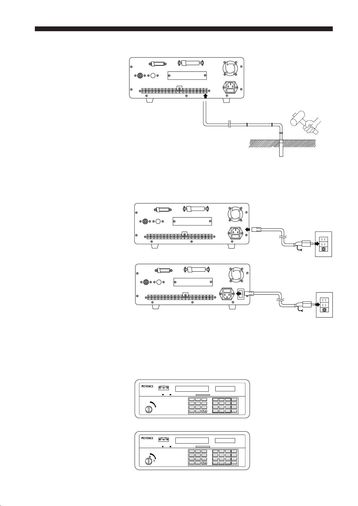
2. Ground the controller. (Except for models followed with “W”.)
Grounding the controller to the
grounding bar
3. Check first that the power switch of the controller is OFF, then connect it to
the outlet using the supplied power cable.
Controller (rear view)
LS-3100 Series
Grounding the
controller through the
grounding outlet
LS-3100(W) Series
I
O
4. Check that laser can be safely emitted, then turn the power switch ON.
Allow the controller to warm-up for approximately 30 minutes after the
laser emission indicator LED has lit.
With the LS-3100(W) series, first turn on the POWER switch (at the rear),
and then turn on the LASER switch (on the front panel).
Controller (front view)
LS-3100 Series
LIMT
HIGH GO LOW
1 2
LASER LASER
LS
LASER SCAN DIAMETER
• OFF
• ON
POWER
OFFSET ZERO HOLD LOCK POSITION
LS-3100(W) Series
LIMT
HIGH GO LOW
1 2
LASER LASER
LS
LASER SCAN DIAMETER
•
•
LASER
OFFSET ZERO HOLD LOCK POSITION
SEG SETMODE
AVE LIMIT OF S
PRM FNC CAL
PROG DISP
SEG SETMODE
AVE LIMIT OF S
PRM FNC CAL
PROG DISP
mm
inch
7
8
9
ZERO
4
5
6
HOLD
1
2
3
CLR
0
.
+/-
ENT
mm
inch
7
8
9
ZERO
4
5
6
HOLD
1
2
3
CLR
0
.
+/-
ENT
5
Page 12
CHAPTER 1 Preparation for Measurement
1-7. Connecting 2 Scanning Heads
CAUTION
Do not connect or disconnect any cables while the power is ON. Otherwise,
the laser diode may deteriorate and/or may be damaged.
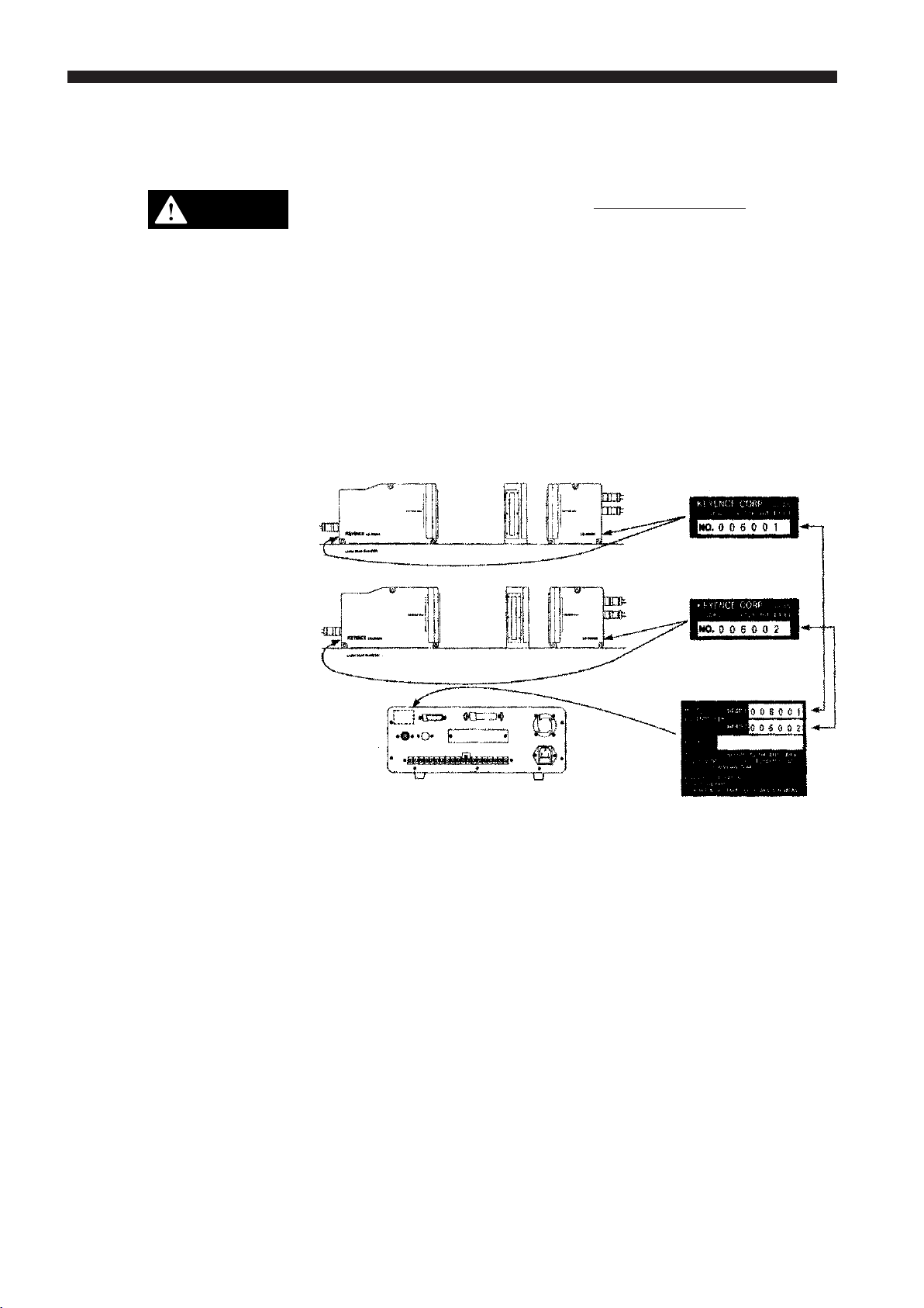
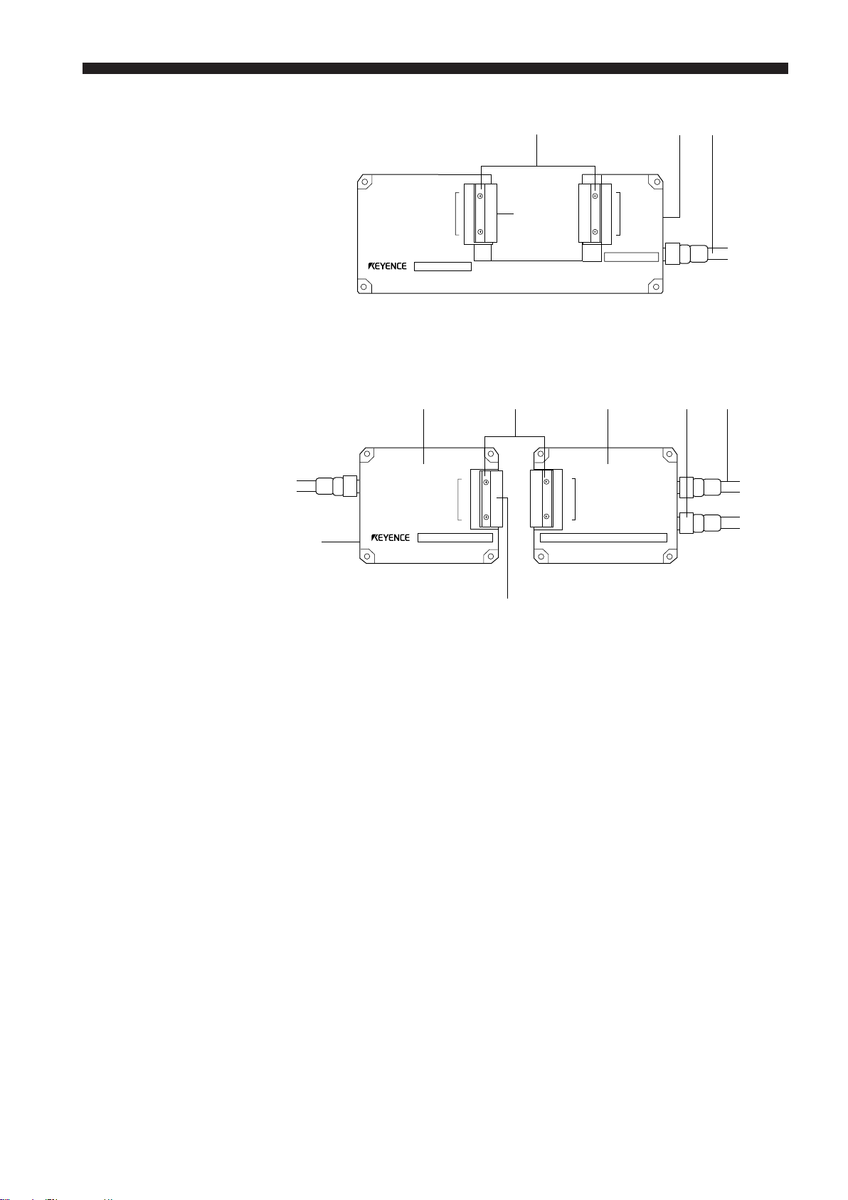
Note the following for connecting 2 scanning heads to the controller:
• These heads have been factory-set for use either as the HEAD1 or
HEAD2. Incorrect connection of the scanning heads will, therefore, result
in malfunction. To prevent this, first check the serial No. of each scanning
head, then check the serial No. of the HEAD1 and HEAD2 on the back of
the controller for correct connection. Each of the scanning heads must be
connected respectively to the HEAD1 or HEAD2 connector on the back of
the controller.
Connect the correct scanning
head to the HEAD1 or HEAD2
connector.
Serial No.
Serial No.
Next, follow the steps (1) through (4) on P4. and 5.
6
Page 13

CHAPTER 2
TRIAL OPERATION
1. Connect the controller and scanning head(s). Make sure that the optical
axis of the transmitter and receiver are aligned before turning the power
ON. Aligning the optical axis is not necessary, however, when using the
single-body type scanning head or when the transmitter and receiver are
secured on the detachable frame.
2. Laser emission starts in approximately 5 seconds.
3. Make sure that the target is correctly positioned in the measurement area.
The measured value will be displayed shortly.
4. The LS controller has been adjusted to the following factory-settings:
Ref.
• DIA: Outer diameter measuring mode. ............................................... P.32
• 1024: Number of measurements for averaging .................................. P.21
• MOVE: Averaging method .................................................................. P.21
CAUTION
Therefore, the displayed value was measured in the above settings. Read
this manual carefully to use the desired settings on your LS controller. To
change each setting, see the table of contents for the corresponding page
No. Some of the most frequently-used operations are given below with the
reference page Nos.
Ref.
• Changing the measurement position of targets .................................. P.32
• Changing the number of measurements for averaging ....................... P.21
• Changing the measurement mode (NORMAL, P-P, PEAK, BOTTOM)P.40
• Measuring two values at a time .......................................................... P.32
• Using two scanning heads to measure (X+Y)/2 .................................. P.32
Do not connect or disconnect any cables while the power is ON. Otherwise,
the laser diode may deteriorate and/or may be damaged.
7
Page 14
CHAPTER 3 Quick Setup Procedures
CHAPTER 3
QUICK SETUP PROCEDURES
The LS Series is a multi-function, versatile laser scan micrometer. This
chapter describes the procedures for setting the LS-3100(W)/3101(W) by
illustrating typical applications.
This chapter covers the procedures needed to make measurements after the
memory is initialized (after "MEMORY INITIALIZED" is displayed).
Initializing Current Settings ........................................................................... 8
How to Use This Chapter ..............................................................................9
Common Settings .........................................................................................9
Setting the Number of Measurements for Averaging ............................... 9
Tolerance Settings .................................................................................10
Initializing Current
Settings
Measurement Procedures .......................................................................... 10
Outer Diameter Measurements .............................................................. 10
Gap Measurement 1 ..............................................................................11
Gap Measurement 2 ..............................................................................11
Measuring Roundness ...........................................................................12
Measuring Eccentricity ...........................................................................12
Measuring Target Displacement within the Measuring Range ..............13
Measuring Edge Movement ...................................................................13
Using LS-3100D(W) Controller with 2 Scanning Heads .............................14
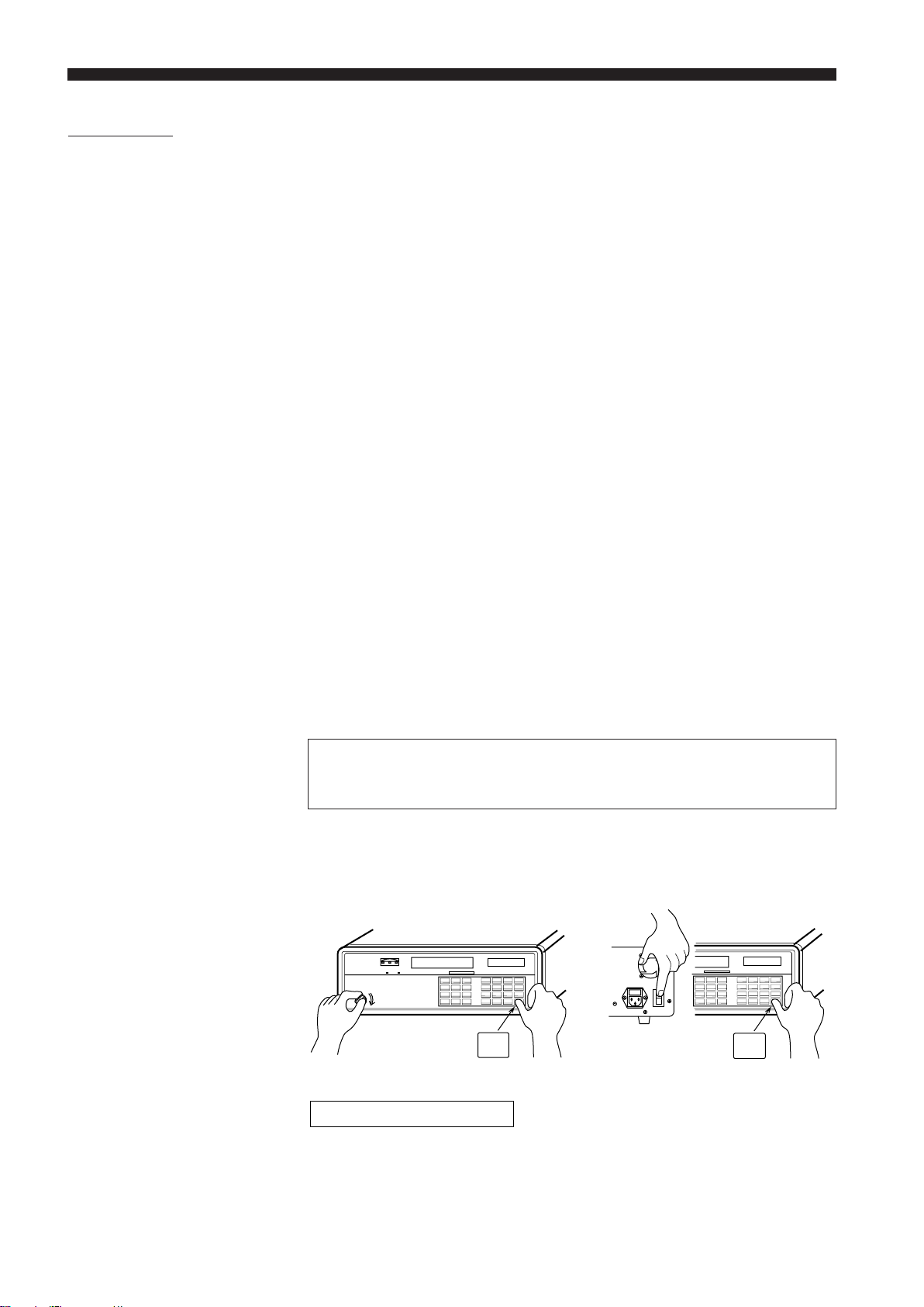
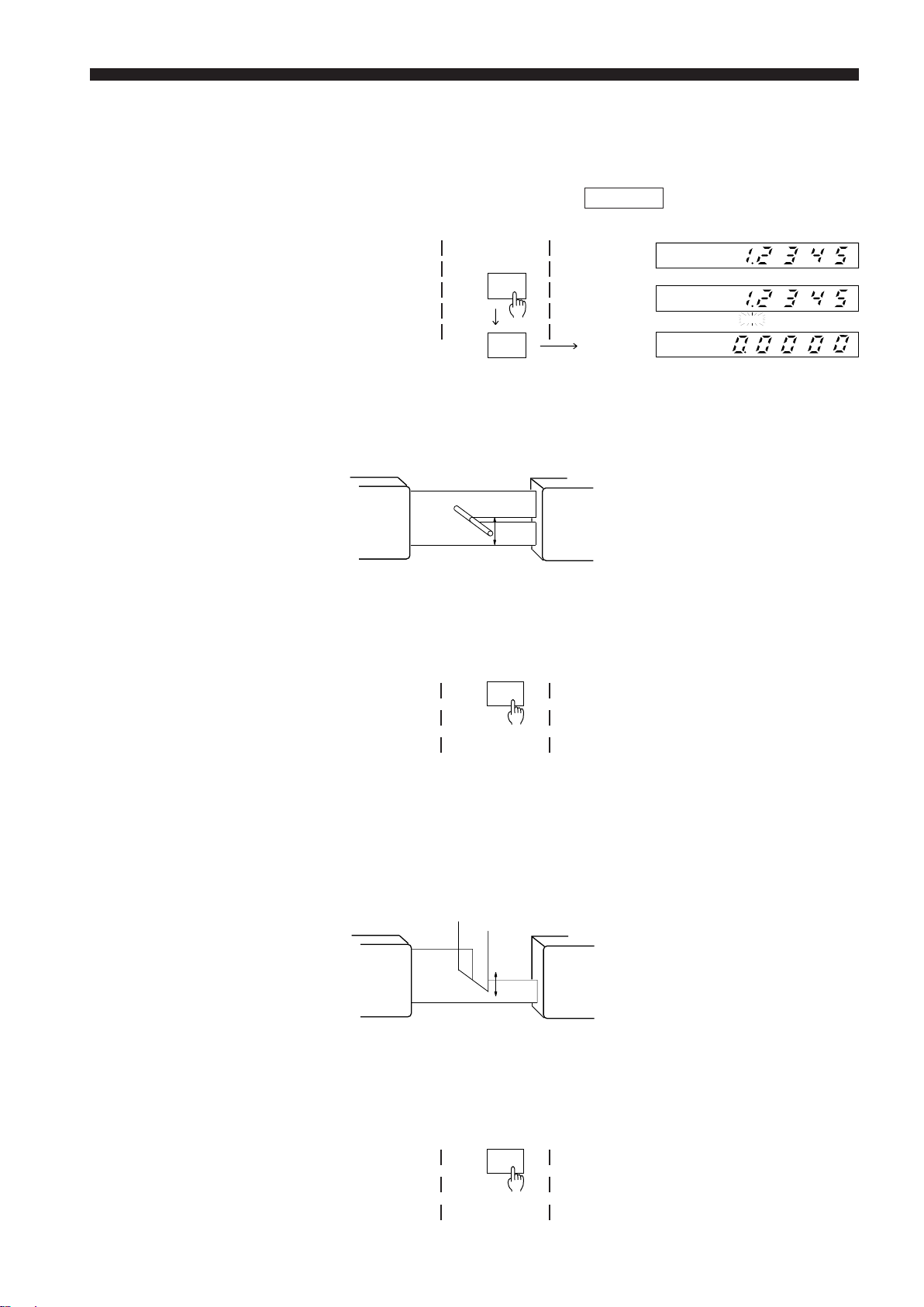
Once a setup is completed, do not initialize the setting again unless
you need to change them. (When initialized, all the current settings
are cleared.)
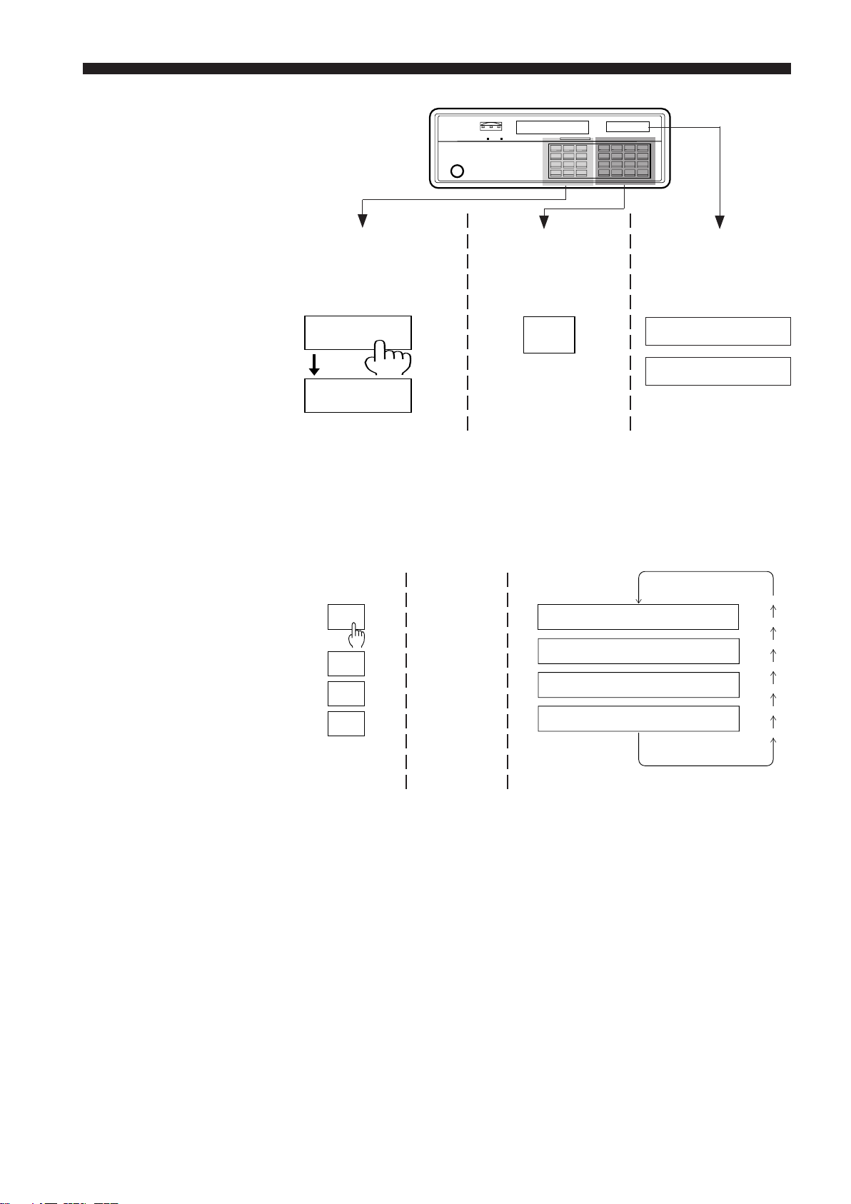
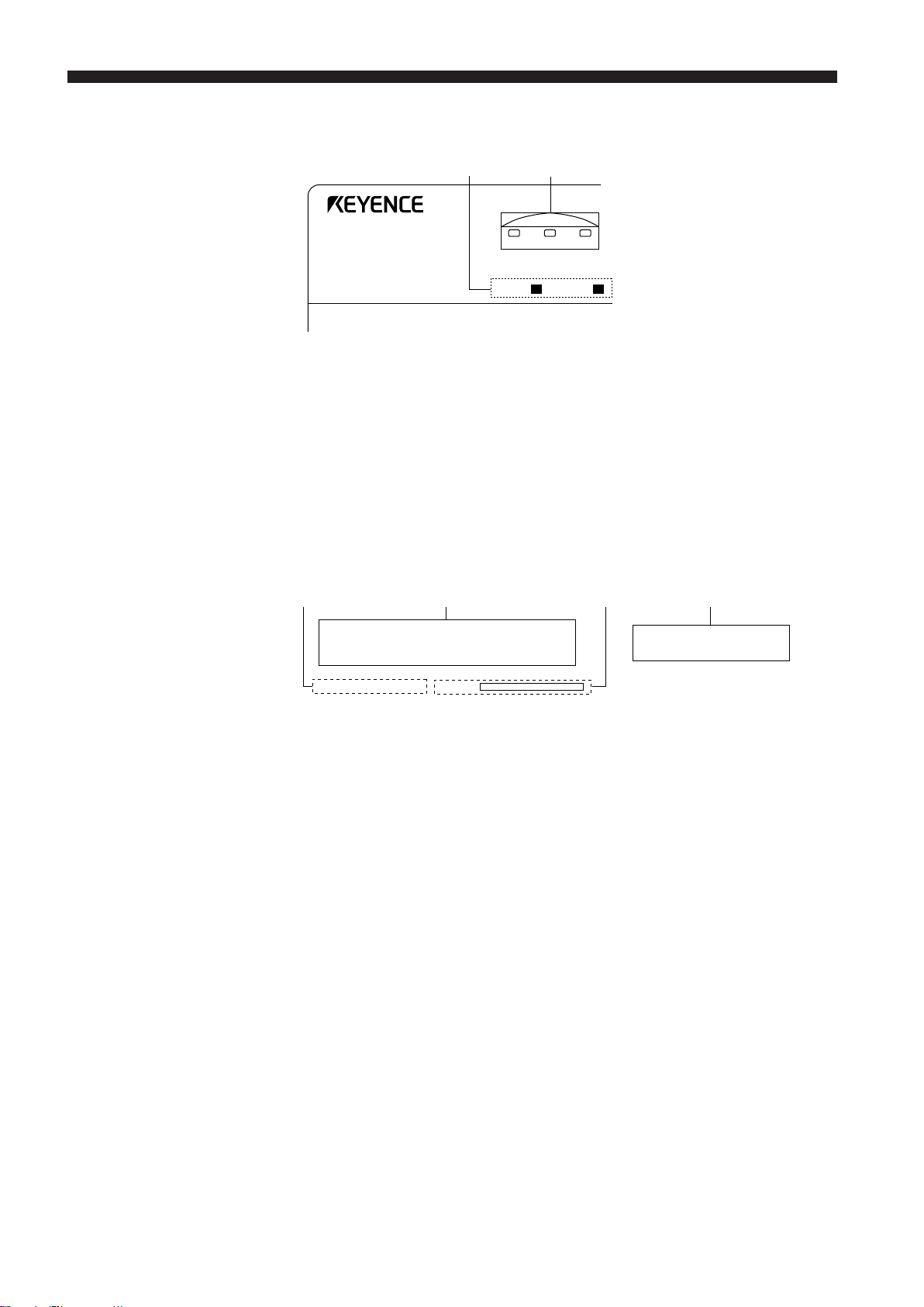
Turn the power switch "ON" while pressing ENT.
LS-3100 Series LS-3100(W) Series
ON
ENT
"MEMORY INITIALIZED" is displayed on the sub-display.
MIENMIOTRIY
All prior settings are cleared and memory initialization is completed.
AL I ZED
ENT
8
Page 15
How to Use This Chapter
CHAPTER 3 Quick Setup Procedures
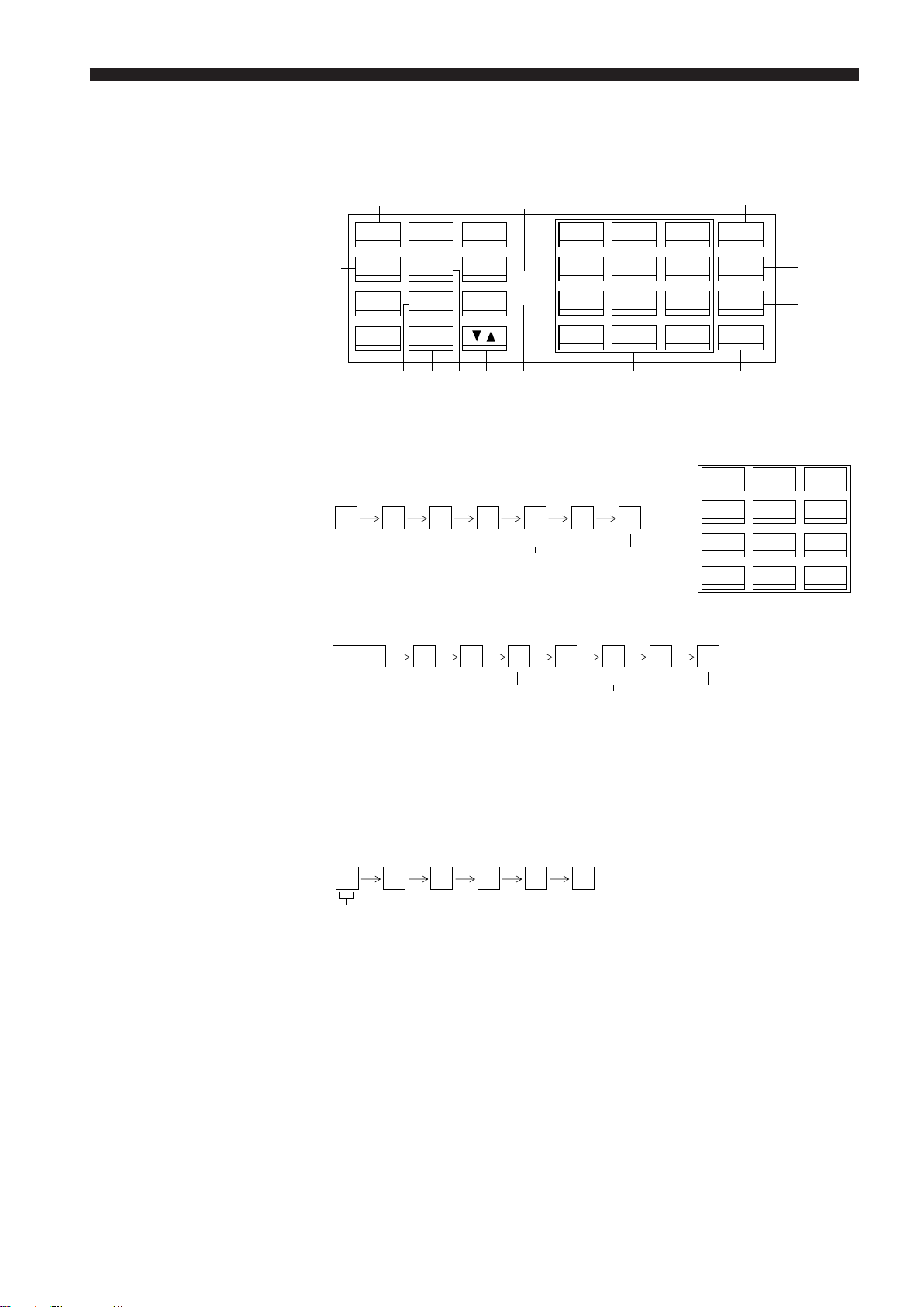
3-1. Common Settings
Setting the Number of Measurements for Averaging
The switches on the left
side of the front panel
are shown on the left
side of the pages in this
chapter.
The switches on the
right side of the front
panel are shown at the
center of the pages in
this chapter.
See page 93 for Measurement Procedures.
AVE
SET
SET
SET
.
.
.
.
AVE 1M0O2V4
AVE
AVE 2
AVE 4
E
S I MPL1E
All massages on the
sub-display are shown
on the right side of the
pages in this chapter.
512
256
128
64
32
16
8
• After initialization, the number of measurements for averaging is automatically set to 1024. "----" appears on the main display for about 3 seconds,
even after a workpiece has entered the measurement range.
• The sampling time required for one measurement is 2.5 m sec. The
sampling time then required for 1024 measurements is 2.56 sec. (2.5 x
1024). The time required to display an averaged measurement changes
depending on the number of measurements being made.
If highly accurate measurement is needed, select 512 or higher as the
number of measurements for averaging.
9
Page 16
CHAPTER 3 Quick Setup Procedures
Tolerance Settings
The following procedure shows how to set the upper limit to 10.5 mm, and
lower limits to 9.5 mm.
LIMIT
OK
1
0
.
5
ENT
9
.
5
ENT
HLIO=
=–6600..00000000
HLIO==[
HLIO==[
HLIO=
HLIO=
HLIO=
HLIO=
HLIO=
HLIO=
HLIO=
HLIO=
–60 . 00010
–60 . 001000
[
=
–60 . 01000.0
[
=
–60 .1000.050
=
–1600..50000000
10 . 5000
=[
10 . 5000
=[
10 . 50090
=[
10 . 5090.0
=[
109..5500000
=
]
]
]
]
]
]
9
]
.
]
5
0
▲
" " moves
to the "LO"
position
For details on tolerance setting for 7-step differentiation, refer to pages 23
through 26.
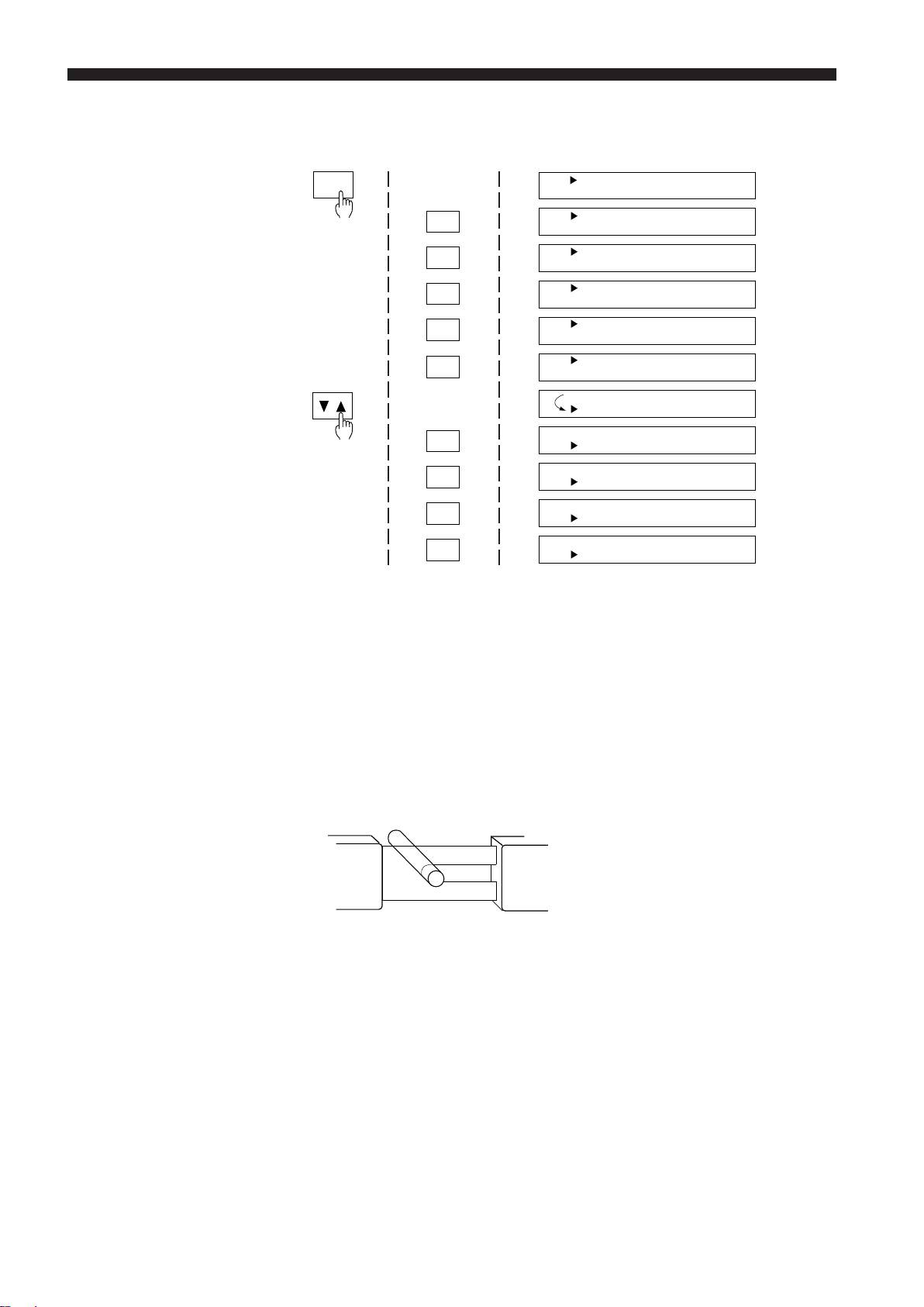
3-2. Measurement Procedures
Outer Diameter Measurements
■ Applications
• Measuring piston outer diameter
• Measuring flat cable width
•Measuring capacitor outer diameter
■ Setting
After "MEMORY INITIALIZED" is displayed, the segment mode is automatically set to DIA (outer diameter measurement).
For details on AVERAGE setting, refer to "AVERAGE", and for details on
tolerance setting, refer to "Tolerance Settings" shown above.
RT
10
• The number of measurements for averaging is set to 1024 after settings
are initialized.
"----" appears on the display for about 3 seconds, even after a target is
placed within the measuring range.
• In the DIA mode, "----" appears on the main display when no workpiece is
within the measuring range.
Page 17
CHAPTER 3 Quick Setup Procedures
Gap Measurement 1
(When part of the target is
outside the optical axis)
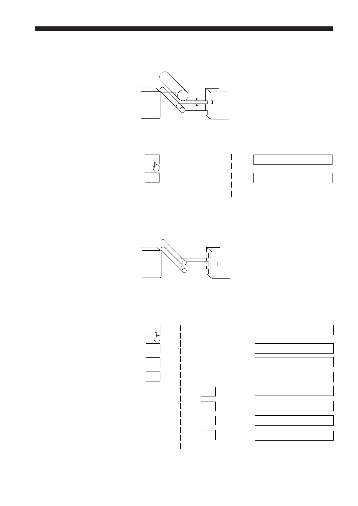
Gap Measurement 2
(When all of the target is
within the optical axis)
■ Applications
• Measuring gap between rollers in a copy machine
• Measuring gap between magnet roller and doctor blade
TR
■ Setting
1. Initialize settings ("MEMORY INITIALIZED" is displayed.)
2.
SEG
SET
OK
SEG D I A
S EG E DGE1
■ Applications
• Measuring pitch of capacitor leads
• Measuring pitch of IC leads
1
TR
2
3
4
5
6
■ Setting
1. Initialize settings ("MEMORY INITIALIZED" is displayed.)
2.
SEG
SET
SET
SET
3
.
4
SEG D I A
S EG E DGE1
S EG E DGE2
SEG [ 2 , 3]
SEG [ 3 , 3 ]
SEG [ 3 , 3 ]
SEG [ 3 , 4 ]
OK
ENT
SEG [ 3 , 4 ]
11
Page 18
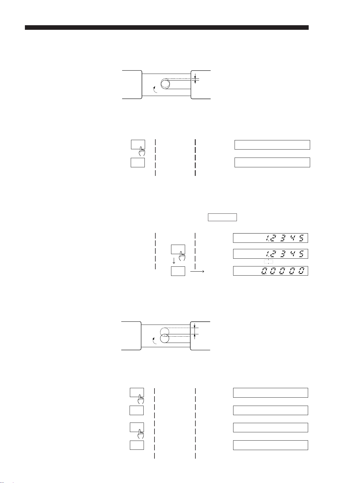
CHAPTER 3 Quick Setup Procedures
Measuring
Roundness
(When target is rotating)
■ Applications
• Detecting uneven rubber roller in a copying machine
• Detecting uneven rubber roller on a printer
RT
■ Setting
1. Initialize settings ("MEMORY INITIALIZED" is displayed.)
2.
MODE
SET
OK
MODE NO MA L
MOD E P–P
R
When the measurement mode is set to "P-P", the displayed value is
retained until HOLD is pressed or until an external signal is input through
the hold synchronous input terminal.
Measuring
Eccentricity
(When target is rotating)
3. Resetting displayed values (When 1. 2 3 4 5 appears on the main
display)
HOLD
HOLD
HOLD
The displayed
Main display
value is reset
to "0".
■ Applications
• Measuring eccentricity of rubber rollers
• Measuring shaft eccentricity for automobile
RT
■ Setting
1. Initialize settings ("MEMORY INITIALIZED" is displayed.)
12
2.
SEG
SET
MODE
SET
OK
SEG D I A
S EG E DGE 1
MODE NOMA L
MODE P–P
Page 19
CHAPTER 3 Quick Setup Procedures
When the measurement mode is set to "P-P", the displayed value is
retained until HOLD is pressed or until an external signal is input through
the hold synchronous input terminal.
3. Resetting displayed values (When 1. 2 3 4 5 appears on the main
display)
HOLD
Measuring Target Displacement within the Measuring Range
Main display
HOLD
The displayed
value is reset
to "0".
■ Applications
•Measuring disk head movement
• Measuring camera lens movement
TR
–
+
■ Setting
1. Initialize settings ("MEMORY INITIALIZED" is displayed.)
Follow the same procedure as that for "Gap Measurement 1".
To reset the current value to "0", press ZERO.
ZERO
HOLD
Measuring Edge Movement
To reset the displayed value to "0" again, press ZERO twice.
■ Applications
•Measuring paper feed for copying machines
• Controlling sheet edges
• Measuring dot printer wire movement
TR
+
–
■ Setting
1. Initialize settings ("MEMORY INITIALIZED" is displayed.)
Follow the same procedure as that for "Gap Measurement 1".
To reset the current value to "0", press ZERO.
ZERO
To reset the displayed value to "0" again, press ZERO twice.
13
Page 20
CHAPTER 3 Quick Setup Procedures
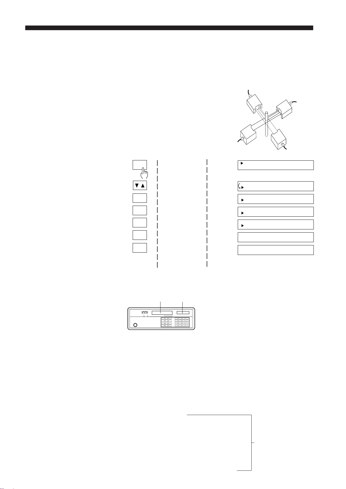
3.3 Using LS-3100D(W) Controller with 2 Scanning Heads
Measuring Outer Diameters in the X and Y Axes
The LS-3100D(W) uses 2 scanning heads for this measurement.
■ Applications
• Measuring outer diameter of coated wire
in the X and Y axes
• Measuring outer diameter of extrusion
molded parts
■ Setting
1. Initialize settings
2.
FNC
SET
SET
SET
DISP
DISP
XY==DDIIA
XY==DDIIA
XY==DEIDA
XY==DEIDA
XY==D2I:A
DNIOA
CNHO2R--
A
A
GE1
GE2
D IA
RMA L
AVE1 024
----------
14
OK
In the above setup, measurements from scanning head 1 are displayed on
the main display, and measurements from scanning head 2 are displayed on
the sub-display.
Measurement value in Y-axis Measurement value in X-axis
For details on tolerance setting, refer to p.23-26, 39, 40, 43 in this manual.
This appendix does not cover all of the LS-3100(W) functions. In addition to
the applications covered in this appendix, the LS-3100(W) can be used for
several other types of measurements.
For more details on functions and measurements, read chapter 4. (A cross
reference between this appendix and chapter 4 is given below.)
Setting number of measurements for averaging .......... p.21
Tolerance settings ........................................................ p.23-26, 39, 40, 43
Measuring outer diameter
Gap measurement 1
Gap measurement 2
Measuring roundness
Measuring eccentricity p.30-32, 40-41, 89-96
Measuring target displacement
within the measuring range
Measuring edge movement
Measuring outer diameter in the X and Y axes
Page 21
CHAPTER 4
FUNCTIONS AND CONTROLS
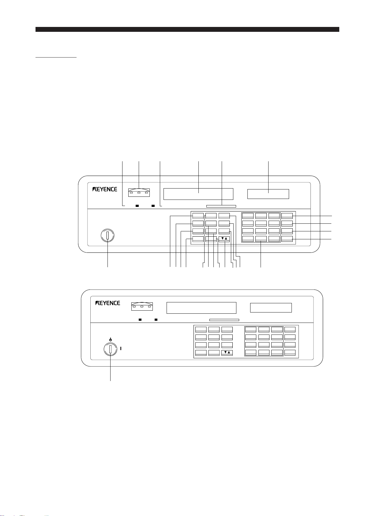
4-1. Part Names
Controller
Model: LS-3100(W)/3100D(W)
Front Panel
LS-3100 Series
LS-3100(W) Series
12 3 45 6
LS
LASER SCAN DIAMETER
• OFF
• ON
POWER
7
LS
LASER SCAN DIAMETER
•
•
LASER
LIMT
HIGH GO LOW
1 2
LASER LASER
LIMT
HIGH GO LOW
1 2
OFFSET ZERO HOLD LOCK POSITION
LASER LASER
OFFSET ZERO HOLD LOCK POSITION
SEG SETMODE
AVE LIMIT OFS
PRM FNC CAL
PROG DISP
SEG SETMODE
AVE LIMIT OFS
PRM FNC CAL
PROG DISP
mm
inch
7
8
9
ZERO
4
5
6
HOLD
1
2
3
CLR
0
.
+/-
ENT
I
H GF E D C BA0 98
mm
inch
J
7
8
9
ZERO
4
5
6
HOLD
1
2
3
CLR
0
.
+/-
ENT
K
L
M
N
7
1 Laser emission indicator LED
2 Comparator output LEDs
3 Current setting indicator
4 Main display (CH1)
5 Target position indicator
6 Subdisplay (CH2)
7 Key-operated power switch
(LS-3100(W) Series: Key-operated
laser switch)
8 SEGMENT key
9 AVERAGE key
(for number of measurements)
0 PARAMETER key
A PROGRAM key
B MODE key
C LIMIT key (for 3-level
comparator output only)
D FUNCTION key
E SUBDISPLAY key
F UP/DOWN key
G CALIBRATION key
H OFFSET key
I SET key
J Numeric keys
K AUTO ZERO key
L HOLD key
M CLEAR key
N ENTER key
15
Page 22
CHAPTER 4 Functions and Controls
ST
WXYZ [\
ST
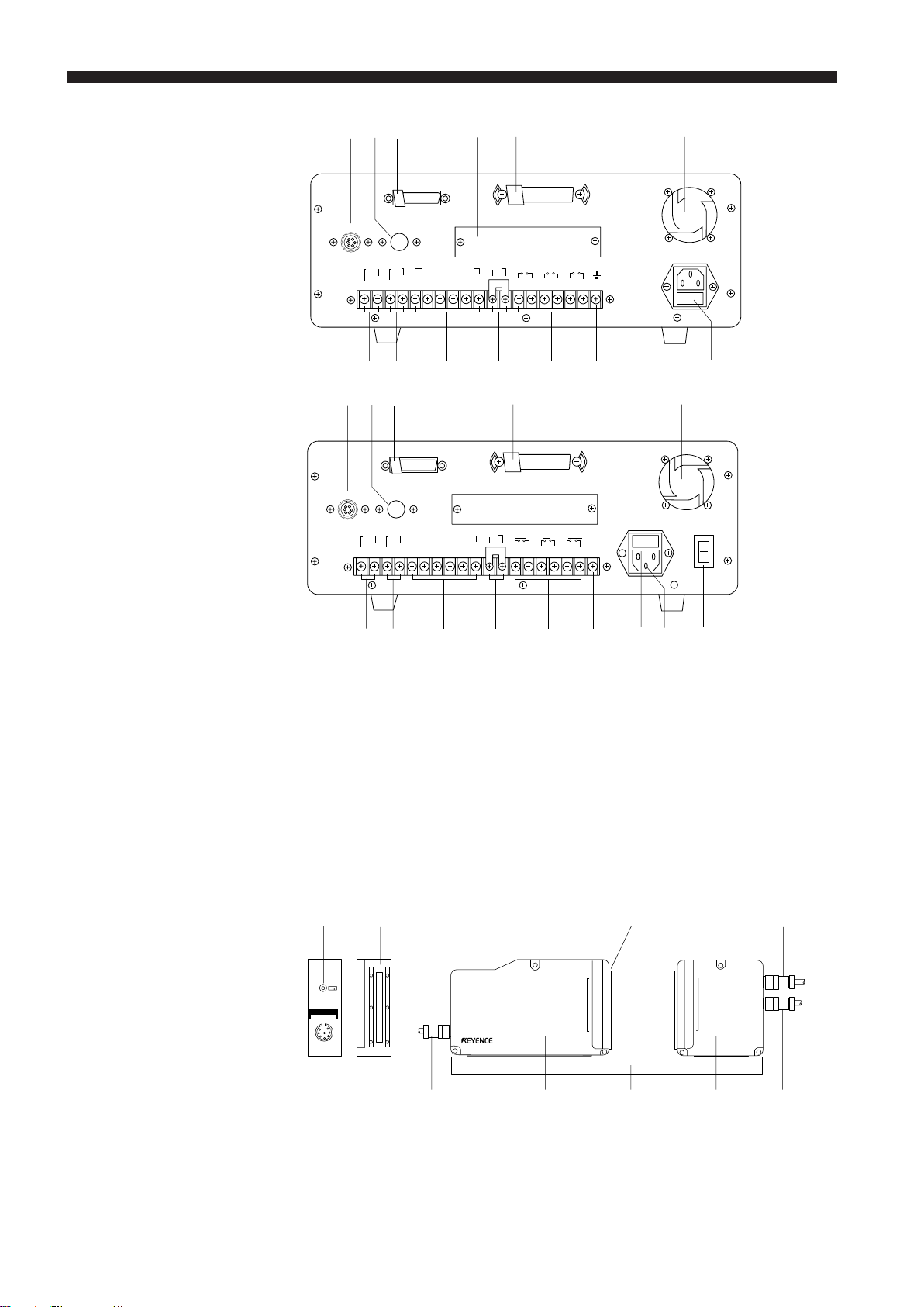
Back Panel
Model: LS-3100
Model: LS-3100(W)
PQ
O
RS - 232C
HEAD 1 HEAD 2
TIMMON
OV GND P1 P2 P 3 P4 P5 GND
1 23 4 5 6 7 8 9 10
UV
PQ
O
RS - 232C
HEAD 1 HEAD 2
TIMMON
OV GND P1 P2 P 3 P4 P5 GND
1 23 4 5 6 7 8 9 10
PROGRAM SELECT
PROGRAM SELECT
R
CONTROL I/O
LASAER
REMOTE
13 14 15 16 17 18 1911 12
R
LASAER
REMOTE
13 14 15 16 17 18 1911 12
LOWGOHIGH
CONTROL I/O
LOWGOHIGH
85~264V AC
2A
85~264V AC POWER
O
2A
I
Scanning Heads
Model: LS-3060
UV WXYZ[
O SCANNING HEAD connector port
P SCANNING HEAD connector port
(for second scanning head)
Q RS-232C connector port
R Expansion I/O port (for optional
BCD or GP-IB interface board)
S 36-pin connector port
(Control I/O port)
T Cooling fan
U Analog voltage output terminals
1. Not used for the LS-3100(W) series.
18
THIS PRODUCT..... ...
CONFORMS
LS-3060T
LASAER SCAN DIAMETER
]\
V Hold synchronous input terminal
W Program selector input terminals
X Laser emission control input
terminals
Y Comparator output terminals
Z Earth ground terminal
[ Power cable receptacle
\ Fuse holder (2A)
] POWER switch
(LS-3100(W) series only)
SCANNING AREA SCANNING AREA
1.
78
LS-3060R
16
26 3 4 56
1 Laser emission indicator LED
2 Protective cover glass
3 Transmitter (T)
4 Detachable frame
5 Receiver (R)
6 8-pin connector cable between
(T) and (R)
7 6-pin connector cable between
the controller and the scanning
head
8 Laser aperture
Page 23
CHAPTER 4 Functions and Controls
Model: LS-3032/3034/3036
Model: LS-3033/3033 SO
9 E0
SCANNING AREA SCANNING AREA
LS-3032
A9 CD
SCANNING AREA SCANNING AREA
F
B
E
LS-3033T
LS-3033R
F
9 Protective cover glass
To prevent lens from being damage or dust from accumulating on the lens
surface (Spares are available for replacement.)
0 Connector cable between the controller and the scanning head (3 m)
A Transmitter (T)
B Receiver (R)
C 6-pin connector cable between the controller and the scanning head
D 8-pin connector cable between (T) and (R)
E Laser emission indicator LED
F Laser aperture
17
Page 24
CHAPTER 4 Functions and Controls
4-2. Indicators and Displays
1
2
LIMIT
HIGH GO LOW
11
1 Laser Emission
11
Indicator LEDs
22
2 Comparator Output
22
LEDs
LS
LASER SCAN DIAMETER
Light when laser is being or about to be emitted from the scanning head.
Only LED [1] lights when one scanning head is used. Both LED [1] and LED
[2] light when two scanning heads are used.
Three LEDs, HIGH, LOW, and GO, are provided. HIGH and LOW light
respectively when the measured value is above the preset upper limit and
below the preset lower limit. GO lights when the measured value is within the
range between these two limits.
3 4 56
OFFSET ZERO HOLD LOCK POSITION
LASER LASER 1 2
mm
inch
33
3 Current Setting
33
Indicator
44
4 Main Display
44
(Channel 1)
55
5 Target Position
55
Indicators
66
6 Subdisplay
66
(Channel 2)
Lights when one of OFFSET, AUTO-ZERO, HOLD, or PANEL LOCK has
been selected.
Shows a measured value.
Indicate where the target is located in the measurement area.
Shows preset values when only one scanning head is used. It shows a
measured value when two scanning heads are used.
A measured value is displayed in 8 digits and updated 10 times per second.
18
Page 25
4-3. Panel Keys
CHAPTER 4 Functions and Controls
11
1 Numeric Keys
11
A
SEG SETMODE
8
AVE LIMIT OFS
9
PRM FNC CAL
G
PROG DISP
B
C 2F
D50E
7
4
1
0
1
8
5
2
.
9
6
3
+/-
6
ZERO
HOLD
CLR
ENT
4
7
3
Enter numbers, a decimal point, and + or - sign. See the following examples:
• Entering +10.0000
10
.
0000
May be defaulted
7
4
1
0
8
5
2
.
9
6
3
+/-
• Entering -10.0000
22
2 SET Key
22
+ / -
10 . 0000
May be defaulted
"+" and "-" alternate each time +/- is pressed. Note that the "+" sign is not
displayed. This key can be pressed to select a positive or negative number
as long as you have only up to 3-digit integers.
• Entering 0.1234
0.1234
May be defaulted
• When you first enter any number by using numeric keys, [ ] appears
on both sides of this number. This indicates that the key input can be
accepted. Any incorrect entry can be deleted using CLR only in this mode.
Changes parameter, setting, and ON/OFF status.
33
3 CLR Key
33
Deletes the desired number. Press ENT to regain the initial data.
19
Page 26

CHAPTER 4 Functions and Controls
44
4 ENT Key
44
55
5 UP/DOWN Key
55
66
6 ZERO (Auto-Zero)
66
Key
Registers the desired number.
Turn ON the power while pressing and holding ENT to return to the factory
settings.
➪
See P.89 to P.96 for the factory settings.
When making certain settings, two of the following items, value, mode or ON/
OFF status, appear at the same time on the subdisplay (CH2). Press this key
to move the cursor up and down to change one of the preset value or status.
Resets the displayed value to "0".
1. Press ZERO to reset the displayed and output values to 0.0000 mm or
0.0000 inch. The "ZERO" indicator below the main display lights when this
key is pressed. From this moment, the main display will only show the
changes in measured value based on the value that has been reset.
mm
inch
OFFSET ZERO HOLD LOCK POSITION
2. Press ZERO again to cancel this mode. The "ZERO" indicator goes out
when this key is pressed.
77
7 HOLD Key
77
• This function is available only for the measured value appearing on the
main display (CH1). Use FNC to reset the measured value on the
subdisplay (CH2) to 0.
➪
See P.39
• This key is invalid when the measurement mode is set to "P-P". At this
time, press HOLD to reset the measured value.
➪
See P.20
• It is also possible to remotely reset the measured value or cancel this
mode by sending a signal through one of the control I/O connector pins.
➪
See P.43
Holds the displayed and output values.
1. Press HOLD to hold the displayed and output values just before this key is
pressed. The "HOLD" indicator below the main display lights when this
key is pressed.
mm
inch
OFFSET ZERO HOLD LOCK POSITION
20
2. Press HOLD again to cancel this mode. The "HOLD" indicator goes out
when this key is pressed.
• If the measurement mode is set to "P-P", "PEAK", or "BOTTOM", the
previously measured value is reset when this mode is cancelled.
• It is possible to use this mode only on the main (CH1) display or on both
the main and subdisplay (CH2). To do this, choose the desired mode
using PRM.
Page 27
CHAPTER 4 Functions and Controls
88
8 AVE Key
88
(Selector key for number
of measurements for
averaging and averaging
method)
Sets the desired number of measurements and averaging method.
1. Use AVE to display the current number and method.
2. To change the number of measurements, use UP/DOWN to move the
cursor up. Then, use SET to specify the number. Each time you press
SET, the number will increment in the following order: "1, 2, 4, 8 ••••• 512,
and 1024". Note also that the number of measurements is set automatically to the currently displayed number. Therefore, you do not need to
press any other key to finalize this number.
AVE
1024
MOV E
3. To change the measurement method, use UP/DOWN to move the cursor
down. Then, use SET to change the averaging method. Each time you
press SET, SIMPLE and MOVE display alternately.
AVE
1024
SIMPLE
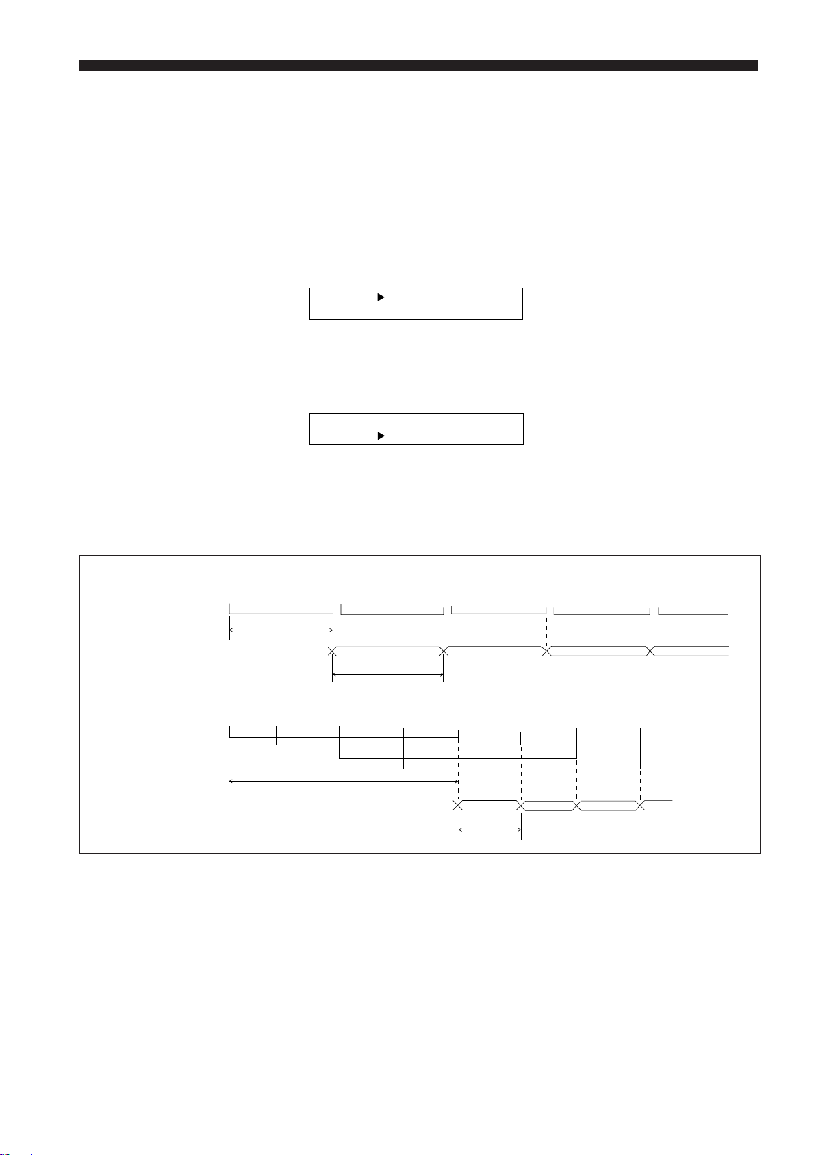
See the timing diagrams below for the difference between these two
methods.
Averaging Methods
Number of samplings
SIMPLE averaging
(Number: 32)
Output cycle of measured value
Number of samplings
MOVE averaging
(Number: 32)
Out put cycle of measured value
1, 2, 3, • • • • • • • 30, 31, 32, 33, 34, 35, • • • • • • 62, 63, 64,65, 66, 67, • • • 94, 95, 96, 97, 98, 99, • • • 126, 127, 128, 129, 130, 131, • • •
1
2.5 ms x number of measurements
2.5 ms x number of measurements
1, 2, • • 7, 8, 9, 10, • • 15, 16,17, 18, • • 23, 24, 25,26, • • 31, 32, 33, 34, • 39, 40, 41, 42, • 47, 48, 49, 50, • 55, 56, 57, 58, • •
2.5 ms x number of measurements
1
23 4
2 34
1
1
20 ms
2
3
23
4
4
* MOVE is valid only when the number of measurements is set to a number
between 16 and 1024.
21
Page 28
CHAPTER 4 Functions and Controls
99
9 PRM Selector
99
Key
Analog Voltage Range
Displays sequentially the following 9 items: preset analog range, "LIMIT",
"DIGIT SUPPRESS", "HOLD", "BAUD RATE", "UNIT", "BUZZER", "HEAD2",
and "POSITION CHECK". Display the desired item first and make the
necessary changes. See the instructions below for making settings in each
item.
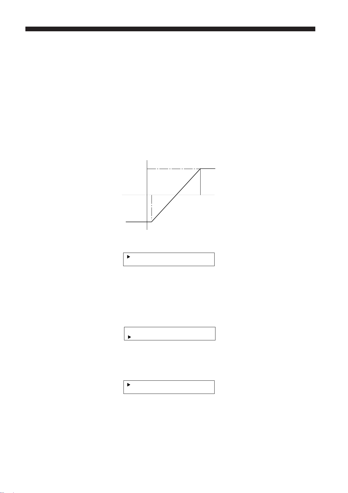
In this mode, measured value is converted into an analog voltage between
-6 V and +6 V. Match the desired measurement range and the above voltage
range. By matching these ranges, the measured value can be converted into
its corresponding voltage.
Determine the upper and lower limits (m) and (n) as shown below. These
values correspond respectively to +6 V and -6 V. This automatically determines the conversion rate of the measurement range against the voltage
range.
Voltage
+6V
n
0
m
Measured value
-6V
1. Use PRM to display the analog voltage range as shown below. UP/DOWN
is not used in this mode.
+6
=
- =-
V6
60. 0V000
0. 0000
6
2. Enter the desired value in mm or inch that corresponds to +6 V.
3. Press ENT to register.
4. When ENT is pressed, the cursor moves down to the second line and the
current preset value corresponding to -6 V disappears.
+6
=
-=
V6
20. 0V000
5. Enter the desired value in mm or inch that corresponds to -6 V.
6. Press ENT to register and finish.
+6
=
-=
V6
20. 0V000
0. 0000
22
7. Use CLR to delete incorrect data and enter the correct one if required.
Page 29
CHAPTER 4 Functions and Controls
[]
[]
[]
[]
[]
[]
[]
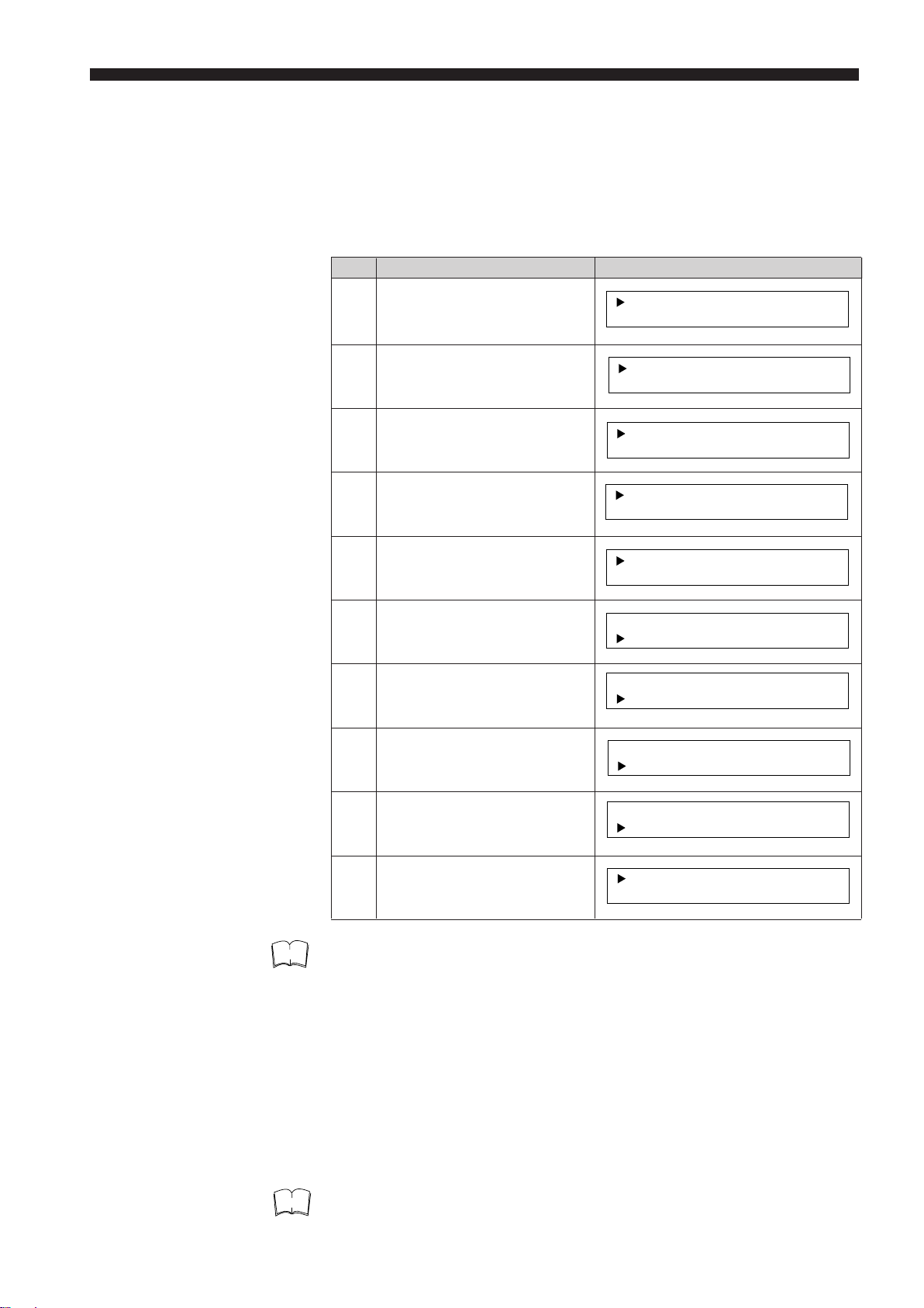
Example of Operation You are to measure the diameter of round bars. The reference diameter is 10
mm, and you wish to convert a difference of 1 mm into 1 V.
In this case, first set 100.000 mm to 0 V. Then, to represent each 1 mm
change in diameter from the reference by 1 V, set the reference plus 6 mm to
+6 V and the reference minus 6 mm to -6 V. That is, +6 V = 16 mm and -6 V
= 4 mm.
Step Key operation Display
1 Use PRM to display analog
voltage range.
2 Press "1".
3 Press "6".
4 Press ".".
5 Press "0" four times.
6 Press ENT
7 Press "4".
8 Press ".".
+6
=
- =-
V6
+6
V
=
-=
+6V
-=
+6V
-=
+6V
-=
+6V
-=
+6V
-=
+6V
-=
-
V6
=
-
V6
=
-
V6
=
-
V6
=
V6
=
V6
=
V6
60. 0V000
0. 0000
6
6 . 0000
0
6 . 0000
0
6 . 0000
0
1 . 00006
6 . 0000
0
1 . 00006
1 . 00006
1 . 00006
1
1.
6
4
4
1
6
.
LIMIT
Note
Note
9 Press "0" four times.
10 Press ENT.
V
=
+6
-=
V6
+6V
=
-=
V6
1 . 00006
4 . 0000
1 . 00006
4 . 0000
• The LS controller is factory-set to +6 V = 60 mm and -6 V = - 60 mm.
•A range of 0.024 mm to 240 mm can be specified.
• Make sure that the value corresponding +6 V is greater than that for -6 V.
• When your reference value is an integer with no decimals, steps 4, 5, 8
and 9 can be omitted.
You can set the following 3 parameters in LIMIT:
• 3-step or 7-step differentiation
• Tolerance limits when 7-step differentiation is selected
• Comparator output type; Relay or open-collector (if the measured value is
above the upper limit or below the lower limit).
• Use FNC to set the tolerance limits for the measured value appearing on
the subdisplay (CH2). ➪
See P.32
23
Page 30
CHAPTER 4 Functions and Controls
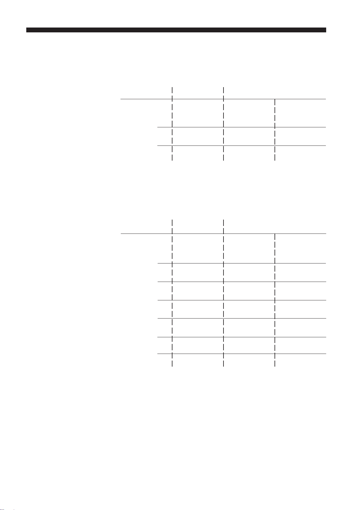
Tolerance Limits and
Comparator Output
■ 3-step differentiation
Choose the 3-step differentiation first, then set the tolerance limits using
LIMIT. When "ON" appears on the display, the comparator output is sent
through each of the relays and open-collectors (HIGH, GO, or LOW).
➪
See P.63, 64
Tolerance limit Condition Output
(Relay) (Open-collector)
HI < X HIGH HI1 (CH1)
HI
HI ≥ X ≥ LO GO GO (CH1)
LO
X < LO LOW LO1 (CH1)
Note: X represents a measured value.
■ 7-step differentiation
Choose the 7-step differentiation first, then set the tolerance limits using
PRM. When "ON" appears on the display, the comparator output is sent
through each of the relays and open-collectors (HI3, HI2, HI1, GO, LO1,
LO2, or LO3).
➪
See P.63
Tolerance limit Condition Output
(Relay) (Open-collector)
HI3 < X HIGH HI3 (CH1)
HI3
HI3 ≥ X > HI2 HIGH HI2 (CH1)
HI2
HI2 ≥ X > HI1 HIGH HI1 (CH1)
HI1
HI1 ≥ X ≥ LO1 GO GO (CH1)
LO1
LO1 > X ≥ LO2 LOW LO1 (CH1)
LO2
LO2 > X ≥ LO3 LOW LO2 (CH1)
LO3
LO3 > X LOW LO3 (CH1)
Note: X represents a measured value.
• It is possible to set the tolerance limits for both 3-step and 7-step differentiation. However, only the tolerance limits of the type of differentiation you
have selected are valid. Therefore, the comparator output is sent according to these limits.
24
• In 7-step differentiation, measured values can be correctly checked only
when the values assigned to the tolerance limits meet the following
condition: HI3>HI2>HI1>LO1>LO2>LO3
Page 31

CHAPTER 4 Functions and Controls
Procedure ■ Switching between 3-step and 7-step differentiations
1. Use PRM to display "LIMIT" (on the subdisplay).
2. To switch between two types of differentiation, use UP/DOWN to move the
cursor up.
I MILTON7CL ASSES
3. Each time you press SET, "7 CLASSES" and "3 CLASSES" are displayed
alternately. Choose the desired type of differentiation.
■ Turning comparator output function ON/OFF
1. Use PRM to display "LIMIT" (on the subdisplay).
2. Use UP/DOWN to move the cursor down.
I MILTON7CL ASSES
3. Each time you press SET, "ON" and "OFF" are displayed alternately.
4. Display "ON" to obtain the comparator output function, or "OFF" to cancel
this output function.
■ Setting tolerance limits (3-step differentiation)
1. First select 3-step differentiation as mentioned above, then use LIMIT to
set the tolerance limits.
➪
See P.29
2. If you press PRM after having set the tolerance limits, "DIGIT SUPPRESS"
will be displayed.
■ Setting tolerance limits (7-step differentiation)
1. First select 7-step differentiation as mentioned above, then use PRM to
set the tolerance limit.
2. "HI1" and "LO1" will appear on the subdisplay. Use UP/DOWN to move
the cursor up for HI1 or down for LO1.
I MILTON7CL ASSES
3. Enter the desired values and press ENT to register.
4. Press PRM.
5. "HI2" and "LO2" will appear on the subdisplay. Enter the desired values
and press ENT to register.
H2
I
LO
=2-
.
30 000.
0
0
30=000
6. Press PRM to display "HI3" and "LO3", enter the desired values, and
press ENT to register.
25
Page 32

CHAPTER 4 Functions and Controls
Example of Operation
You are to measure the diameter of round bars. The reference diameter is
10 mm. You wish to perform a 7-step differentiation with the following tolerance limits: ±0.1 mm, ±0.2 mm, ±0.3 mm.
Step Key operation Display
1 Press PRM to display
"LIMIT".
I MILTON3CL ASSES
2 Use UP/DOWN to move
cursor up.
3 Use SET to display "7
CLASSES".
I MILTON3CL ASSES
I MILTON7CL ASSES
4 Press PRM to display "HI1"
and "LO1".
H1
I
LO
-
=1-
10 000.
.
0
0
10=000
5Enter 10.1000 for HI1 and
9.9000 for LO1, then press
ENT.
I
H1
LO
=
=1
10
00
1
..
9
.
0
009
0
6 Press PRM again to display
30=000
"HI2" and "LO2".
I
H2
LO
=2-
.
30 000.
0
0
DIGIT SUPPRESS
7Enter 10.2000 for HI2 and
9.8000 for LO2, then press
ENT.
H2
I
LO
=
=2
10
00
2
..
9
.
0
008
0
8 Press PRM again to display
"HI3" and "LO3".
I
H3
LO
=3-
.
60 000.
0
0
60=000
9Enter 10.3000 for HI3 and
9.7000 for LO3, then press
ENT.
H3
I
LO
=
=3
10
..
9.007
00
3
0
0
Deletes fractions from measured value on the display. DIGIT SUPPRESS is
useful when there is a relatively large difference from one measured value to
another. The possibly applicable cases are listed below.
• When the number of measurements for averaging is set to a small number
• When the target is vibrating
•When it is not necessary to obtain precise measurements
This prevents errors involved in reading measured values.
26
• This function can be used for both the main display and subdisplay. It
becomes invalid when the subdisplay is used to show measured values in
P-P, PEAK, or BOTTOM mode.
• Although fractions are not displayed, the target is measured down to
0.0001 mm and comparator output sent based on these measured values.
Page 33

CHAPTER 4 Functions and Controls
Procedure
HOLD
Procedure
1. Use PRM to display "DIGIT SUPPRESS" (on the subdisplay).
IG
I T
UDS0PPRESS CH2 0
CH1
2. Use UP/DOWN to move the cursor up or down, then use SET to choose
how many fractions you wish to delete. Each time you press SET, the
subdisplay will show "0", "1", "2", "3", "4", and "0" again.
3. Note that they represent the number of digits to be deleted starting from
the rightmost (smallest) fraction.
Selects whether to use HOLD function (see P.20) only for CH1 or for both
CH1 and CH2.
1. Use PRM to display "HOLD" (on the subdisplay).
C1
OLD
H
H
2. Each time you press SET, "CH1" and "CH2" are displayed alternately.
Display "CH1" only for CH1 or "CH2" for both CH1 and CH2.
BAUD RATE
Procedure
UNIT
Procedure
Selects the data transmission speed via RS-232C interface.
1. Use PRM to display "BAUD RATE" (on the subdisplay).
T1
B
AUD
EA R 2 00
2. Each time you press SET, the baud rate will increment from 75 to 19200.
Display the desired choice.
Selects the unit of measurement between mm and inch.
1. Use PRM to display "UNIT" (on the subdisplay).
NIT
mUm
2. Use SET to display "mm" or "inch".
The unit selected in this mode will be applied to other values such as
tolerance limits and calibration values.
27
Page 34

CHAPTER 4 Functions and Controls
BUZZER
Turns ON/OFF the beep during panel key operation.
Procedure 1. Use PRM to display "BUZZER" (on the subdisplay).
UZZ NBOER
2. Use SET to display "ON" or "OFF".
HEAD2
Procedure
Selects whether to use two scanning heads or not.
1. Each time you press SET, "ON" and "OFF" are displayed alternately.
2. Display "ON" to use two scanning heads or "OFF" to use just one head.
EADHN2O
The controller must be equipped with the optional PC board for the second
scanning head. If not, an error message "H2-Err" appears on the main
display. In such a case, display "HEAD2 OFF" (on the subdisplay). This will
cause "H-Err" to appear on the main display. Then, turn OFF the power
once, then turn it ON again. You can now perform measurements using only
the first scanning head (HEAD1).
POSITION CHECK
(Model: LS-3033/3060 only)
Procedure
Checks whether the transmitter and receiver are aligned in terms of the
optical axis of the laser. This alignment is required when these units are
removed from the detachable frame during operation.
➪
See "Mounting Scanning Head" in Chapter 5 on P.65 for details.
1. Use PRM to display "POSITION CHECK".
EADH1
OS TP IOI N CHECK
2. Align the transmitter and receiver in terms of the optical axis.
3. When two scanning heads are used, press PRM again to display
"HEAD2" above "POSITION CHECK", and align the second set of
transmitter and receiver.
H2
EAD
OS TP IOI N CHECK
28
Page 35

CHAPTER 4 Functions and Controls
[]
00
0 LIMIT
00
(Tolerance limits
for 3-step
differentiation)
Key
This key is used to set the tolerance limits (upper and lower) for measured
values on the main display (CH1). If the measured value is above the upper
or below the lower limit, the comparator output is sent through the corresponding relay and open-collector.
➪
See P.24 for the relationship between the tolerance limits and types of output obtained.
• Use FNC to set the tolerance limits for the subdisplay (CH2).
➪
See P.39
Procedure 1. Use LIMIT to display the current tolerance limits.
2. HI and LO represent respectively the upper and lower limits.
3. Use UP/DOWN to move the cursor up or down.
HI
LO= - 60 . 0000
60. 0=000
4. Enter the desired tolerance limits.
Make sure that the value for HI is greater than that for LO.
5. Press ENT to register.
Example of Operation
6. Use UP/DOWN again to move the cursor, and enter another tolerance
limit.
7. Use CLR to delete any incorrect entry.
You are to measure the diameter of round bars. The reference diameter is
10 mm. You wish to perform a 3-step differentiation with the tolerance limits
of ±0.1 mm (upper limit=10.1 mm, lower limit=9.9 mm).
Step Key operation Display
1 Press LIMIT to display
current tolerance limits.
HI
LO= - 60 . 0000
60. 0=000
2 Enter tolerance limit.
10. 1=000
[
HI
LO= - 60 . 0000
]
3 Press ENT to register.
10. 1=000
10. 1=000
4 Press UP/DOWN to move
cursor.
HI
LO= - 60 . 0000
HI
LO= - 60 . 0000
5Enter another tolerance
limit.
6 Press ENT to register.
HI
LO= - 9 . 9000
HI
LO= 9. 9000
10. 1=000
10. 1=000
29
Page 36

CHAPTER 4 Functions and Controls
AA
A SEG (Segment)
AA
Key
Definition of Segment
Note
Targets placed within the measurement area interrupt the passage of the
laser beam, thus creating a light-dark pattern. The border between the light
and dark regions is referred to an "edge". Also, each dark or light region
separated by the edge is called a "segment".
Transmitter Receiver
Edge1
Edge2
Edge3
by laser
Direction of scanning
Targets
Edge4
Edge5 (X-1)
Edge6 (X)
The desired pair of edges is to be selected from those shown above, and the
distance between these two edges measured.
• The edges are numbered in the order that they are scanned by the laser
(from top to bottom).
• The desired pair from among up to 126 edges can be selected.
Description
4 types of segment pairs, DIA, EDGE1, EDGE2, (m,n), can be measured.
The description of measurement for each pair is given below.
DIA: This mode is applicable to measurement of targets’ outer diameters. In
the above figure, the distance between edge 2 and edge (X-1) is measured.
When there is only one target, its outer diameter is measured. When there
are two or more targets, the distance between the upper edge of the upper
most target to the lower edge of the lower most target is measured.
EDGE1: The width of the uppermost region where the laser is not interrupted by the target is measured. This mode is applicable to measurement of
changes in targets’ diameters. In the above figure, the distance between
edge 1 and edge 2 is measured.
EDGE2: The width of the lowermost region where the laser is not interrupted
by the target is measured. In the above figure, the distance between edge
(X-1) and edge X is measured.
(m,n): The distance between two desired edges is measured. When measuring two or more targets, this mode is applicable to measurement of the
outer diameter of each target or to measurement of the gap between two
targets.
In (m,n) mode, both "m" and "n" represent the edge numbers ranging from 1
to 126. Make sure that the number specified for "n" is greater than that for
"m".
30
Page 37

CHAPTER 4 Functions and Controls
Procedure
1. Press SEG to display the current segment pair (on the subdisplay).
SEG D I A
2. Each time you press SET, the subdisplay will sequentially show "DIA",
"EDGE1", "EDGE2", "(m,n)", then "DIA" again. Display the desired segment pair. You do not need to press any other key. (When two scanning
heads are used, the subdisplay will sequentially show "DIA", "EDGE1",
"EDGE2", "(m,n)", "2:DIA", "2:EDGE1", "2:EDGE2", "2:(m,n)", and "DIA"
again.)
3. To measure the distance between two desired edges, select the (m,n)
mode.
S E G ( 5, 2 )
4. Use SET to display "(m,n)" first.
SEG ( ,
)
nm
5. Enter the desired edge numbers.
➪
See the example of operation given below for details.
6. Press ENT to register.
Example of Operation You are to measure the gap between two round bars (between edges 3 and
4). Suppose that the currently registered edges are 2 and 3.
Step Key operation Display
1 Press SEG.
SEG D I A
2 Use SET to display current
edges (2 and 3).
SEG ( 2 , 3 )
3 Press "3".
SEG ( 3 , 3 )
4 Press ".".
SEG ( 3 , 3 )
5 Press "4".
SEG ( 3 , 4 )
6 Press ENT.
SEG ( 3 , 4 )
31
Page 38

CHAPTER 4 Functions and Controls
Note
• If you enter invalid numbers (other than 1 through 126) and press ENT,
the initial edge numbers will remain on the subdisplay.
• Basically, two numbers are entered in this mode. If by mistake you enter
the larger number on the left and smaller number on the right, and press
ENT, the smaller number will appear on the left and larger number on the
right.
S E G ( 4, 3 )
ENT
S E G ( 3, 4 )
• Clear objects can be used as targets only in DIA, EDGE1, and EDGE2
modes, but not in SEG (m,n) mode.
• Use CLR to delete any incorrect values.
• In the above example operation, if you need to change only the first edge
number, that is, from 2 to 1, follow only steps 1, 2, 3, and 6.
BB
B FNC (Function)
BB
Key
Segment Selector
• Similarly, if you need to change only the second edge number, that is,
from 3 to 5, follow only steps 1, 2, 4, 5, and 6.
Is used for the following settings:
• Segment selector
Selection of measurement points (2-point simultaneous measurement)
• Segment check
Inhibiting output of measurements obtained under abnormal conditions
• Output channel
Selection of output channel for displaying measured values X and Y and
calculation of equations using these values
• MODE, OFFSET, and LIMIT for CH2
Selection of mode for CH2, offset value, and tolerance limit
Description of each setting is given below.
In this mode, two segments are to be specified for simultaneous 2-point
measurement. Just as with the SEG key, any of four types of segments can
be specified respectively for segment selectors X and Y. (See P.30.) By
selecting two different segments, the LS controller can measure two different
segments at the same time.
32
Page 39

CHAPTER 4 Functions and Controls
Procedure 1:
Measuring 2 Segments with 1
Scanning Head
1. Use FNC to display the current segments for X and Y.
X D
=
Y=
IIADA
2. Use UP/DOWN to move the cursor up.
3. Each time you press SET, "DIA", "EDGE1", "EDGE2", "(m,n)", and "DIA"
will sequentially appear on the right of "X=". Display the desired segment.
* "m" and "n" in (m,n) represent two desired edge numbers.
X
=I
DA
DG
EI
EY=
4. When you have selected "(m,n)", enter the desired edge numbers, and
press ENT to register.
➪
See P.31.
Once you select "(m,n)" for X, "(m,n)" will be automatically selected for Y.
X
Y
(
= 2, 3
(
=
1, 2
)
)
5. Use UP/DOWN to move the cursor down.
X
Y
(
= 2, 3
(
=
1, 2
)
)
Example of Operation
6. Repeat steps 3 and 4.
You are to measure the outer diameter and eccentricity of the round bars
using one scanning head.
Edge 1
Y
Edge 2
X
Edge 3
Edge 4
Transmitter
Receiver
Step Key operation Display
1 Use FNC to display current
X D
Y=
=
IIADA
segments.
2 Use UP/DOWN to move
X D
cursor up.
Y=
=
IIADA
3 Use SET to display:
(1) "X= DIA"
(2) "X= (m,n)". Enter 2 for
"m" and 3 for "n", and press
ENT.
X D
=
Y=
X
= 2, 3
Y
=
(
(
IIADA
1, 2
(To be continued)
)
)
33
Page 40

CHAPTER 4 Functions and Controls
Procedure 2:
Using 2 Scanning Heads
4 Use UP/DOWN to move
cursor down.
X D
=
Y=
X
= 2, 3
Y
=
(
(
IIADA
1, 2
5 When you have selected
X
=I
"DIA" in step 3, use SET to
display
DA
DG
EY=
EI
"Y= EDGE1".
When you have selected
"(m,n)" in step 3, enter 1 for
X
Y
(
=
1, 2
(
= 2, 3
"m" and 2 for "n", and press
ENT.
Press PRM first, and check that "HEADS2 ON" is displayed on the
subdisplay.
1. Use FNC to display current segments.
2. Use UP/DOWN to move cursor up.
)
)
)
)
Example of Operation
3. Each time you press SET, the subdisplay will sequentially show "DIA",
"EDGE1", "EDGE2", "(m,n)", "2:DIA", "2:EDGE1", "2:EDGE2", "2:(m,n)",
and "DIA" again. Display the desired segment.
* "m" and "n" in (m,n) represent two desired edge numbers.
* "2:" in "2:DIA", for example, represents the second scanning head.
4. When you have selected "(m,n)", enter the desired numbers, and press
ENT to register.
➪
See P.31.
X
Y
(
= 2, 3
(
=
1, 2
)
)
5. Use UP/DOWN to move the cursor down.
X
Y
(
=
1, 2
(
= 2, 3
)
)
6. Repeat steps 3 and 4.
Measuring the outer diameter of 2 round bars at the same time using 2
scanning heads
Step Key operation Display
1 Use FNC to display current
X D
segments.
=
Y=
IIADA
34
2 Use UP/DOWN to move
cursor up.
3 Use SET to display "X=
DIA"
X
Y=
X
Y=
D
=
IIADA
D
=
IIADA
(To be continued)
Page 41

4 Use UP/DOWN to move
cursor down.
CHAPTER 4 Functions and Controls
X D
=
Y=
IIADA
5 Use SET to display
Note
• Some combinations of segments cannot be used with the LS controller.
See the table below. ("✓" indicates valid combinations.)
DIA EDGE1 EDGE2 (m,n) 2: DIA 2: EDGE1 2: EDGE2 2: (m,n)
DIA
EDGE1
EDGE 2
✓
✓
✓
(m,n)
2: DIA
2: EDGE 1
Segment selector Y
2: EDGE 2
2: (m,n)
✓
✓
✓
✓
• Even when you have selected the segments using segment selectors X
and Y, these segments will be replaced by those selected using SEG.
When using SEG, be sure to select the same segments again.
"Y=2:DIA".
X
Y=
IIADA:2
D
=
Segment selector X
✓✓ ✓ ✓ ✓
✓
✓
✓
✓
✓
✓
✓
✓
✓
✓
✓
✓
✓
✓
✓
✓
✓
✓
✓
✓
✓
✓
✓
✓
✓
✓
✓
✓
✓
✓
✓
✓
✓
✓
✓
✓
✓
✓
✓
✓
Segment Check
This mode is applicable to segment mode (m,n). In this mode, you are to
register the number of segments. If the number of segments detected during
measurement is not the same as the registered one, error message " - - - - "
will appear. When this happens, the measured value is ignored.
This prevents incorrect measurements due to dust, drops of oil, or any other
particles on the scanning head. The error message will also appear when
the target is displaced from the measurement area.
•Non-clear targets are being measured.
1
2
3
4
5
6
ReceiverTransmitter
Segment selectors
X=(2. 3)
Y=(4. 5)
The registered number of edges is 6. If more than 6 edges are detected due
to dust as shown below, " - - - - - " will be displayed.
Floating dust
1
2
3
4
5
6
7
ReceiverTransmitter
* The segment check mode does not function with segment pairs in the
DIA, EDGE1, and EDGE2 modes.
35
Page 42

CHAPTER 4 Functions and Controls
Procedure Check first that segment pair, (m,n), has been selected.
1. Use FNC to display "X SEG CHECK OFF".
SCEGX HECK OF F
4
2. Use SET to display "ON" on the right of "SEG CHECK" to activate the
segment check mode.
SCEGX HE CK ON
4
* When the currently selected segment pair is DIA, EDGE1, or EDGE2, "Y
SEG CHECK" will be displayed.
3. Enter the correct number of edges.
4. Press ENT to register.
5. Press FNC to display "Y SEG CHECK OFF".
6. Repeat steps 3 and 4.
Example of Operation
You are to measure the outer diameter of two round bars at the same time
using one scanning head. You need to use the segment check mode to
prevent incorrect measurements. In this case, the number of edges is 6.
1
2
3
4
5
6
ReceiverTransmitter
Segment selectors
X=(2. 3)
Y=(4. 5)
Step Key operation Display
1 Use FNC to display "X SEG
CHECK OFF".
SCEGX HECK OF F
4
2 Press SET.
SCEGX HE CK ON
4
3 Enter "6".
4 Press ENT to register.
SCEGX HECK ON
SCEGX HECK ON
[]
6
6
36
5 Press FNC.
6 Press SET.
7 Press "6".
8 Press ENT to register.
SCEGY HECK OF F
4
SCEGY HECK ON
4
SCEGY HE CK ON
SCEGY HECK ON
[
]
6
6
Page 43

CHAPTER 4 Functions and Controls
Output Channel
The LS controller is equipped with two output channels (CH1 and CH2)
having their own displays and output terminals for simultaneous 2-point
measurement.
In this mode, you are to select which output channel to display or output
each of the measured values for X and Y. You can also choose to select the
equation containing X and Y as variables and obtain the result.
Types of output for CH1 and CH2
Channel Display Output
Main display
3 comparator LEDs (HI,
GO, LO)
CH1
3-step comparator output (relay)
➪
See P.64.
7-step comparator output
(control I/O)
Analog voltage output
RS-232C
BCD (option)
GP-IB (option)
➪
➪
See P.49.
➪
See P.62.
See P.68.
➪
See P.70.
➪
See P.47.
Subdisplay 3-step comparator output
CH2
(control I/O)
➪
See P.62.
RS-232C
GP-IB (option)
* For the subdisplay you can use DISP to display the current settings,
measured value for CH1 in one of the measurement modes, or measured
value for CH2. Therefore, the subdisplay may not show the measured
value of the segment you have selected. However, the comparator output
and the BCD output will be sent based on the measured value of the
segment selected using the segment selectors.
Procedure 1. Use FNC to display the current segment pairs for the output channels.
C HX1=
CH2= Y
2. Use UP/DOWN to move the cursor up.
3. Each time you press SET, the subdisplay will sequentially show "X", "Y",
"X+Y", "X-Y", "(X+Y)/2", "(X-Y)/2", "-X", "-Y", "-(X+Y)", "-(X+Y)/2", and "X"
again.
Choose the desired segment selector or equation.
4. Use UP/DOWN to move the cursor down.
C
HX1=
CH2= Y
5. Repeat step 3.
Equations
It is possible to choose the desired equation having X and Y as variables.
You can display and output the result of the equation through CH1 or CH2 or
both. Eight equations are available as mentioned in step (3) of the above
procedure.
37
Page 44

CHAPTER 4 Functions and Controls
Equation Display or output
-X Negative X or Y value, or Remainder of OFFSET value
-Y
from which X or Y is subtracted (if OFFSET value is
registered)
X+Y Addition of X and Y
X-Y Subtraction of Y from X
(X+Y)/2 Average of X and Y
(X-Y)/2 Subtraction of Y from X, then division by 2
-(X+Y) Addition of X and Y, and negative of this result, or
Negative remainder of OFFSET value from which
addition of X and Y is subtracted (if OFFSET value is
registered)
-(X+Y)/2 Negative average of X and Y
Negative remainder of OFFSET value from which
average of X and Y is subtracted (if OFFSET value is
registered)
➪
See P.43 or OFFSET value.
Example of Operation
You are to measure the outer diameter of the round bar and its eccentricity
with one scanning head. The measured value of the diameter will be displayed and output through CH1. The measured value of the eccentricity will
be displayed and output through CH2. Suppose that the following parameters have been set for CH1:
MODE: NORMAL
AVE: 512 MOVE
OFFSET: 0.0000
LIMIT: HI 20.0000
Y
X
Segment Selectors
X=DIA
Y=EDGE1
LO -20.0000
Transmitter
Receiver
Step Key operation Display
1 Use FNC to display current
segment selectors.
X
Y=
IIADA
D
=
2 Use UP/DOWN to move
cursor up.
X
Y=
IIADA
D
=
3 Use SET to display
X D
"X=DIA".
Y=
=
IIADA
38
4 Use UP/DOWN to move
cursor down.
5 Use SET to display
"Y=EDGE1".
6 Use FNC to display current
equations for output channels.
7 Use UP/DOWN to move
cursor up.
X D
=
Y=
X
=
Y=
HX1=
C
CH X2= + Y
C HX1=
CH X2= + Y
IIADA
IDGDA
E
EI
(To be continued)
Page 45

CHAPTER 4 Functions and Controls
MODE, OFFSET, and LIMIT
for CH2
8 Use SET to display
"CH1=X"
C HX1=
CH X2= + Y
9 Use UP/DOWN to move
C
cursor down.
HX1=
CH X2= + Y
10 Use SET to display
C
"CH2=Y".
HX1=
CH2= Y
After step 10, each time you press FNC, the subdisplay will show the current
measurement mode (one of NORMAL, P-P, PEAK, BOTTOM), OFFSET
value, and tolerance limits. Be sure to select the parameters for CH2 in the
same manner as you do for CH1.
Use FNC to select the MODE, OFFSET, and LIMIT parameters. Note that
only 3-step differentiation is available for CH2 and that its output is sent
through the corresponding control I/O connector pins.
Enter the desired parameters for MODE, OFS (OFFSET), and LIMIT.
➪
See P.40 for MODE, P.43 for OFFSET, and P.29 or LIMIT.
Procedure 1. First select the desired segment pair for the segment selectors and
equations for the output channels.
➪
See P.32 and P.35.
2. Press FNC once to display the current measurement mode.
3. Each time you press SET, the subdisplay will show sequentially "NORMAL", "P-P", "PEAK", and "BOTTOM". Display the desired mode.
4. Press FNC again to display the current OFFSET value.
5. Enter the desired value, and press ENT to register.
* OFFSET value is factory-set to "0.0000". Do not change it unless
otherwise required.
6. Press FNC again to display the current tolerance limits.
7. Use UP/DOWN to move the cursor up.
8. Enter the desired value, and press ENT to register.
9. Use UP/DOWN to move the cursor down.
10. Enter the desired value, and press ENT to register.
39
Page 46

CHAPTER 4 Functions and Controls
Example of Operation Continued from P.39, you are to select "P-P" for measurement mode and
"0.1 mm" for tolerance upper limit. By selecting 0.1 mm, the comparator
output will be sent through CH2 if the measured value is above this limit.
Step Key operation Display
11 Press FNC once to display
current mode.
HO2MC DE NORMA L
12 Use SET to display "P-P".
HO2MC DE P-P
13 Use FNC to display current
OFFSET value.
HF2OC FS TE
.0 0000
14 Do not change OFFSET
value. Press FNC again to
display current tolerance
CH
60. 02000
H
- 60. 0000
L
limits.
CC
C MODE Key
CC
Switching Measurement
Modes
15 Use UP/DOWN to move
cursor up.
CH
60. 02000
H
- 60. 0000
L
16 Enter "0.1000".
[]
CH
H
L
0.12000
- 60. 0000
17 Press ENT to register.
CH
H
L
0.12000
- 60. 0000
• When you finish setting the parameters, use DISP to show measured
values for CH2 on the subdisplay.
• Even when the subdisplay shows the current settings or measured value
in one of the measurement modes for CH1, the comparator output and
BCD output will be sent based on the measured value for CH2.
• NORMAL
Measured value is displayed or output as is.
• P-P (PEAK to PEAK)
The difference between the maximum (Peak) and minimum (Bottom)
values measured during the specified period is displayed and output.
40
• PEAK (PEAK HOLD)
The maximum value measured during the specified period is displayed
and output.
• BOTTOM (BOTTOM HOLD)
The minimum value measured during the specified period is displayed
and output.
Page 47

CHAPTER 4 Functions and Controls
• "Specified period" refers to the duration of time from when a measurement
mode is set until when the mode is cancelled by pressing HOLD or inputting a signal through terminal TIM.
• Use FNC to set the measurement mode for CH2.
➪
See P.39.
Procedure
1. Press MODE to display the current measurement mode.
OM DE NORMA L
2. Each time you press SET, the subdisplay will show sequentially "NORMAL", "P-P", "PEAK", and "BOTTOM". Display the desired mode.
DD
D CAL (Calibration)
DD
Key
In this mode, the LS controller can be calibrated to correct possible measurement errors arising from irregularities on the target surface or inclination
of the target. Have ready two gauges of known dimension for calibration.
The LS controller can be calibrated for each of segment selectors X and Y.
Procedure 1. Press CAL to calibrate segment selector X. "CAL X" will appear on the
subdisplay. At this time, the segment pair (SEG) remains the same.
However, the number of measurements for averaging (AVE) and measurement mode (MODE) will be set respectively to "1024, MOVE" and
"NORMAL". The LS controller will be reset to the initial parameters when
the calibration is over. Also, the hold and auto-zero functions are cancelled, and the offset function is invalid during calibration.
CL
A
0X000.
0 00 0.
0
0
2. Place a reference gauge in the measurement area to display the measured value (on the main display). Make sure that the displayed value is
not changing before you proceed to the next step.
3. Enter the known dimension of the reference gauge, then press ENT to
register. The cursor will move down, and the initial value will disappear
automatically when you press ENT.
A
CL
1
0
0X000.
4. Place another reference gauge in the measurement area, enter its dimension, and press ENT to register.
5. When the parameters are correctly set, "CALIB OK" will appear on the
subdisplay. If not, "CALIB ERROR" will appear. Check the measured
value and reference gauges for any errors, and repeat steps 1 to 4.
AKI
CLB
O
41
Page 48

CHAPTER 4 Functions and Controls
6. Press CAL to calibrate segment selector Y. "CAL Y" will appear on the
subdisplay. You can display "CAL Y" by pressing CAL either when "CALIB
OK" appears or when "CAL X" has just been displayed by pressing CAL.
("CAL X" and "CAL Y" display alternately each time you press CAL.)
Note
CL
A
0Y000.
0 00 0.
0
0
7. Repeat steps 2 to 5 just as you do for calibrating segment selector X.
8. When you finish the calibration, press any of SEG, MODE, AVE, LIMIT,
OFS, PRM, FNC, PROG, or DISP to return to the measurement mode.
• To return to the factory calibration, enter "0.0000" on the upper and lower
lines of the subdisplay.
• When "CALIB ERROR" appears on the subdisplay, press CAL to display
the return to the previous status.
• When you use only one of the segment selectors X and Y, you can
calibrate only the selector you use. When you finish the calibration, first
check that "CALIB OK" appears on the subdisplay, then press any of the
keys mentioned in Step 8 to return to the measurement mode.
• When you measure the diameter of two round bars with only one scanning head, the measurement position differs one from the other. To
ensure higher accuracy, it is recommended that the reference gauge be
placed at each position and segment selectors X and Y be calibrated
separately.
• For even higher accuracy, the closer the dimension of the reference
gauge to the target size, the better.
• You cannot enter negative values.
• The value entered on the lower line of the subdisplay must be greater
than that on the upper line. If not, "CALIB ERROR" will appear.
Example of Operation You are to measure a diameter of round bars that can vary from 10 mm to
20 mm. Two gauges, each having 10.0100 mm and 20.1000 in diameter are
used for calibration.
Step Key operation Display
1 Press CAL to display "CAL
X".
CL
A
0X000.
0 00 0.
0
0
2 Enter "10.0100".
A
CL
[1
0 00 0.
0
]
0
0X010.
3 Press ENT to register.
0X010.
Cursor will move down.
A
CL
1
0 00 0.
0
0
42
(To be continued)
Page 49

CHAPTER 4 Functions and Controls
EE
E DISP
EE
(Subdisplay) Key
4 Enter "20.1000".
5 Press ENT to register.
"CALIB OK" will appear.
6 Press CAL to display
"CAL Y".
7 Repeat steps 2 to 5 to
calibrate Y.
One of the following items appears on the subdisplay:
• Status of settings during panel key operation
• Measured value for CH1 in NORMAL, P-P, PEAK, or BOTTOM mode
Measured value in any of the desired mode can be displayed regardless
of the mode set using MODE. The comparator output and BCD output will
be sent based on the mode set using MODE.
CL
A
AKI
CLB
CL0Y
A
0X010.
1
[
0 10 0.
2
O
0 00 0.
0
0
]
000.
0
0
• Current settings for CH1
Current parameters or modes set using SEG, MODE, or AVE can be
displayed.
• Measured values for CH2
Each time you press DISP, the values or parameters mentioned in (2), (3),
and (4) will display alternately.
* These values or parameters cannot be changed on the subdisplay.
FF
F OFS (Offset) Key
FF
Procedure 1. Press OFS.
Offset value is set in this mode. This value is added to the measured value,
and the total value is displayed and output. Any value between -999.9999
and 9999.9999 can be specified as an offset value. If the diameter of a round
bar or width of a sheet material is too large to measure with one scanning
head, offset value can be used to measure it using two scanning heads. In
this case, the diameter or width is displayed or output in absolute value.
* Use FNC to set the offset value for CH2.
➪
See P.39.
2. Enter the desired offset value.
3. Press ENT to register.
Example of Operation
43
Page 50

CHAPTER 4 Functions and Controls
You are to measure the diam- eter of a round bar. This diameter, supposedly 100 mm, is displayed and
output in absolute value.
HEAD1
X
D
Edge1
Edge2
HEAD2
Y
Transmitter Receiver
Edge1
Edge2
Place two scanning heads as shown above.
Enter the following segment pair for the segment selectors and equation for
the output channel:
Segment selector X= EDGE 1 or EDGE 2
Y= 2: EDGE 1 (when EDGE 2 is selected for X) or
2:EDGE 2 (when EDGE 1 is selected for X)
Output channel CH1= -(X+Y)
With the above parameters, you will obtain values X and Y in the figure.
Value D, diameter of the target, is obtained by subtracting values X and Y
from the width of the measuring area. To obtain the width of the measuring
area, add values X, Y, and D. This width is used as the offset value.
See P.37 for the segment selectors and output channels.
Have ready a target of known diameter. Suppose that its diameter is
100.1000 mm, and that values X and Y are measured to be 35.2345 mm and
36.1234 mm, respectively.
Step Key operation Display
1 Use FNC to set segment
X E
pair for X and Y.
➪
See P. 32.
= DGE I
Y=
2 EDGE 2:
2 Use FNC to set equation for
CH1 and CH2. Values X
and Y are obtained.
➪
See P.37.
3 Use DISP to display X and
Y. Take a note of these
values.
4 Use FNC again to set
equation for CH1 and CH2.
Target diameter is to be
displayed and output
through CH1.
5 Press OFS to display
"OFFSET".
6 Enter "171.4579".
* 171.4579 is the total of X,
Y, and D.
7 Press ENT to register, or
press CLR and reenter
correct value.
C
HX1=
CH2= Y
35 2. 345
CH
2 36 1. 234
NO
R
C H-1=
CH Y2=
OFEF
ST
0 00 0.
OFEF
ST
[
1.47
1
F
OFE
ST
1.47
1
()
X+Y
0
]
5
7
9
5
7
9
44
Page 51

CHAPTER 4 Functions and Controls
GG
G PROG (Program)
GG
Key
The LS controller can store the currently displayed settings. Up to 10 types
of settings can be stored with each assigned a program number. Each type
of settings can be retrieved through its program number for quicker operation.
* BAUD RATE, BUZZER ON/OFF, HOLD type, HEAD2 ON/OFF, and
POSITION CHECK cannot be stored.
Storing (SAVE) Settings 1. Enter the desired parameters.
2. Press PROG to display "PROG".
R OG
P1SALOAD
VE
3. Enter the desired program No.
4. Press ENT to register. At this moment, only the program No. has been
selected.
5. Use UP/DOWN to move the cursor down to "SAVE".
6. Press SET to display "SA OK?". Press ENT to accept or CLR to cancel.
R OGP5SALOAD
OK ?
7. When you enter ENT, the settings will be stored under the selected
program No. When you press CLR, you can resume from step 3.
Example of Operation Storing the current settings under program No.6.
Step Key operation Display
1 Press PROG.
R OGP2SALOAD
2 Enter "6".
P6SALOAD
R OG
3 Press ENT.
R OGP6SALOAD
4 Use UP/DOWN to move
R OG
cursor down.
P6SALOAD
5 Press SET.
R OG
P6SALOAD
VE
][
VE
VE
VE
OK ?
6 Press ENT to accept.
R OG
P6SALOAD
VE
45
Page 52

CHAPTER 4 Functions and Controls
Retrieving (LOAD) Settings 1. Press PROG to display "PROG".
2. Enter the desired program No.
R OGP1SALOAD
VE
3. Press ENT to accept. At this moment, only the program No. has been
selected.
4. Use ON/OFF to move the cursor up to "LOAD".
5. Press SET to display "LO OK?". Press ENT to accept or CLR to cancel.
R OGP2SALO OK
6. When you press ENT, the settings stored under the specified program No.
will be retrieved.
7. When you press CLR, you can resume from step 3.
Example of Operation Retrieving program No.3
Step Key operation Display
1 Press PROG.
2 Enter "3".
3 Press ENT.
4 Use UP/DOWN to move
cursor up to "LOAD".
VE
?
P1SALOAD
R OG
VE
P3SALOAD
P3SALOAD
[]
R OG
VE
R OG
VE
R OGP3SALOAD
VE
46
5 Press SET.
6 Press ENT to retrieve.
P3SALO OK
R OG
R OG
P3SALOAD
?
VE
VE
• Program can be retrieved by using the program selector input terminals or
control I/O connector port.
➪
See P.62.
• See P.49 for storing and retrieving programs through the RS-232C interface.
Page 53

Tab le of I/O
Terminals
CHAPTER 4 Functions and Controls
Analog Voltage Output
Analog voltage signal for CH1 can be obtained through the MON terminals.
The LS controller has been factory-set to convert a range from -60 mm to
+60 mm into a voltage range from -6 V to +6V. (No voltage signal is provided
for CH2. If voltage signal for CH2 is required, consult the KEYENCE distributor.)
Analog voltage range: A range between -6 V and +6 V can be set to
match a desired measurement range. Any value between -999.9999 and
9999.9999 can be selected. Note, however, that the difference between the
maximum and minimum measurements (those that you specify to correspond respectively to +6 V and -6 V) must fall within a range between 0.024
mm and 240 mm.
Calibration: When the segment selectors are calibrated, the analog voltage
signal through these terminals and RS-232C interface is automatically sent
based on the calibrated value.
Offset: When the segment selectors are calibrated, the selected offset
value is added to the analog voltage signal sent through these terminals and
RS-232C interface.
The analog voltage which appears on the main display and that which is
output through the MON terminals are always the same.
Comparator Output
For CH1 (Channel 1)
7-step differentiation
CH1
3-step differentiation
Tolerance Limit Output Device/Terminal
HI3
HI2
HI1
GO
LO1
LO2
LO3
HIGH
GO
LOW
HIGH
GO
LOW
HI1
GO
LO1
HIGH
GO
LOW
CH1
CH1
Control I/O (open-collectors)
Front panel (LEDs)
Comparator output terminals (relays)
Control I/O (open-collectors)
Front panel (LEDs)
For CH2 (Channel 2)
CH2
Only 3-step
differentiation is
available.
HIGH
GO
LOW
HI
GO
LO
CH2
Comparator output terminals (relays)
Control I/O (open-collectors)
47
Page 54

CHAPTER 4 Functions and Controls
Program Selector Input
Terminals
AUTO ZERO Terminals
The desired program No. can be selected from external equipment using the
following terminals:
<Terminal Block> program selector input:
Programs 1 to 5 selectable
<Control I/O> terminals #2 to #11:
Programs 1 to 10 selectable (program selector input)
Note that when two or more terminals are grounded at the same time, the
program with the smallest number will be selected.
Auto Zero function can be activated or deactivated from external equipment
using the following terminals:
<Control I/O> zero set terminal:
Ground to activate Auto Zero function
<Control I/O> zero reset terminal:
Ground to deactivate Auto Zero function
Auto Zero function can be activated as many times as desired without being
deactivated.
HOLD Terminal
Laser Emission Control
Input Terminal
Hold function can be activated or deactivated from external equipment using
the following terminals:
<Terminal Block> HOLD synchronous input:
Ground to activate and open to deactivate HOLD function
<Control I/O> synchronous input:
Ground to activate and open to deactivate HOLD function
Unlike Auto Zero function, no terminal is provided for deactivating the Hold
function. That is, while each of the above terminals is grounded, the Hold
function remains activated. However, this function remains deactivated when
the terminal is left open.
The laser emission indicator LED lights when this terminal is left open,
stopping the emission of the laser beam. For shipment, a jumper is provided.
<Terminal Block> Laser Remote:
Ground to stop and open to release the emission
48
Page 55

4-4. I/O Terminal
CHAPTER 4 Functions and Controls
RS-232C I/O Terminal
Specifications
Pin Assignment
The LS controller is provided with the RS-232C interface, which allows the
LS controller to communicate with an external computer. Data transmission
or change of the settings can be remotely performed.
The LS controller employs the RS-232C interface (recommended standard
by EIA: Electronic Industries Association) for data transmission. LS controller
is defined as "MODEM".
Communication parameters
Duplex Full
Synchronization Start-stop
Data format ASCII
Data length 8 bits
Stop bit length 1 bit
Parity check None
Baud rate 75/150/300/600/1200/2400/4800/9600/19200 bps*
*Selectable by setting
D-sub 25 pin female connector
111213
2425
6 7 8 91 0
20212223
21345
141516171819
Pin 20 is internally connected to the power source via a pull-up resistor. This
pin remains ON unless it is grounded. Therefore, measurement data can be
output regardless of whether pin 20 is connected to external equipment.
Pin No. Modem signal code Modem signal Direction
1 Shield Shield (to signal ground) –
2 SD (TXD) Input data from external Input
equipment
3 RD (RXD) Output measurement data Output
to external equipment
5 CS (CTS) ON (High) at power-on Output
6 DR (DSR) ON (High) at power-on Output
7 SG (GND) Signal ground –
8 CD (DCD) ON (High) at power-on Output
20 ER (DTR) Enables output of Input
measurements to external
equipment when ON (High)
49
Page 56

CHAPTER 4 Functions and Controls
Connector Pin Assignment
Remote Operation
Use straight type cable.
Connection example 1 Connection example 2
Pin No. Pin No. Pin No. Pin No.
(PC) (LS) (PC) (LS)
11 11
22 22
33 33
55 77
66 4
77 6
88 8
20 20
In addition to the pin connections shown here, all identically-numbered pins of PC
and LS controller can be
connected.
11
22
..
..
..
5
20
OO
The settings and data output can be performed using external equipment
such as a computer, instead of the front panel keys of the LS controller. This
operation method is referred to as remote operation. The items which can be
remotely operated are divided into four sections (setting of measurement
conditions, setting of output conditions, output of measurement data and
output of setting status), and are described in the following.
"Format" used in the following description means input form.
Setting Measurement
Conditions
[P$] [S$] [H$] List
Set the measurement conditions for the desired program. The format differs
with the setting item, as described below.
Format:
([P$] [S$] [H$] ) [COMMAND] CR
Head No. (Scanning head No.)
Segment No. (Segment Selector)
Program No.
Note that one or more of the commands in ( ) can be omitted.
When [P$] is omitted, the current program No. will be valid.
When [S$] is omitted, the current segment selector will be valid.
When [H$] is omitted, the current scanning head will be valid.
Function Command Description
Specifying [P$] P1 Specifies program No. 1
(Program No.) P2 Specifies program No. 2
P3 Specifies program No. 3
P4 Specifies program No. 4
P5 Specifies program No. 5
P6 Specifies program No. 6
P7 Specifies program No. 7
P8 Specifies program No. 8
P9 Specifies program No. 9
PA Specifies program No. 10
Specifying [S$] X Specifies segment selector X
(Segment selector) Y Specifies segment selector Y
Specifying [H$] 1 Specifies scanning head No. 1
(Scanning head No.) 2 Specifies scanning head No. 2
50
Page 57

CHAPTER 4 Functions and Controls
[COMMAND] List
Function Command Description
Specifying segment SS Specifies segment check ON
check SR Specifies segment check OFF
Nn Specifies the number of
segments ("n") for segment check
Specifying D Specifies DIA
measurement segment E Specifies EDGE1
F Specifies EDGE2
Sm, n Specifies values ("m" and "n)
for SEG (m, n) (m < n)
Setting number of A0 Sets 1
measurements A1 Sets 2
for averaging A2 Sets 4
A3 Sets 8
A4 Sets 16
A5 Sets 32
A6 Sets 64
A7 Sets 128
A8 Sets 256
A9 Sets 512
AA Sets 1024
Setting averaging BS Sets simple (SIMPLE) averaging
method BM Sets sequential (MODE)
averaging (Valid only when the
number of measurements is set
to any of 16, 32, 64, 128, 256,
512 and 1,024)
Setting program to LDn Loads program No. "n"
be loaded
Setting program to SVn Saves current settings into be saved
program No. "n"
Locking panel key RS Locks panel key operation
operation RR Cancels locking of panel key
Commands for setting functions
Setting UM Sets "mm"
measurement unit UI Sets "inch"
Setting channel to J1 Sets CH1 only
which HOLD J2 Sets both CH1 and CH2
function is applied
Setting AUTO ZERO ZS Sets AUTO ZERO function
function ZR Cancels AUTO ZERO function
Setting HOLD HS Sets HOLD function
function HR Cancels HOLD function
operation
• When the command for locking of panel key operation is entered, any
change of settings cannot be performed using the panel keys. At this time,
setting indicator LOCK lights.
• If there is an error in the format, all the commands in that format are
disregarded.
• Only one command for setting various functions can be entered for one
format.
51
Page 58

CHAPTER 4 Functions and Controls
Entry Examples
• To specify "1" for program No., "Y" for segment selector, "1" for scanning
head No., and SEG (3, 4) for measurement segment: "P1Y1S3,4 CR"
• To specify "2" for program No., "X" for segment selector, and "OFF" for
segment check: "P2XSR CR"
• To specify "3" for program No., "X" for segment selector, "1" for scanning
head No., and "DIA" for measurement segment: "P3D CR"
• To set the number of measurements for averaging to 1,024, while not
changing the other settings on the front panel: "AA CR"
Setting Output Conditions Sets the output conditions (processing methods for measured values) for the
desired program. The format differs with the setting item, as described
below.
Format:
( [P$] [C$] ) [COMMAND] CR
Channel No.
[P$] [C$] List
[COMMAND] List
52
Program No.
Note that one or more of the commands in ( ) can be omitted.
When [P$] is omitted, the current program No. will be valid.
When [C$] is omitted, the current channel No. will be valid.
Function Command Description
Specifying program No. P1 Specifies program No. 1
P2 Specifies program No. 2
P3 Specifies program No. 3
P4 Specifies program No. 4
P5 Specifies program No. 5
P6 Specifies program No. 6
P7 Specifies program No. 7
P8 Specifies program No. 8
P9 Specifies program No. 9
PA Specifies program No. 10
Specifies output channel V Specifies output channel CH1
W Specifies output channel CH2
Function Command Description
Setting tolerance IS Sets tolerance differentiation
differentiation output output to ON
IR Sets tolerance differentiation
output to OFF
Setting tolerance T3 Sets 3-level differentiation
differentiation level T7 Sets 7-level differentiation (3 or 7)
Setting tolerance TAn Sets value ("n") for HIGH3
range for 7-level TBn Sets value ("n") for HIGH2
differentiation TCn Sets value ("n") for HIGH1
TDn Sets value ("n") for LOW1
TEn Sets value ("n") for LOW2
TFn Sets value ("n") for LOW3
Setting values ASm, n Sets "m" for +6 V, and "n" for -6 V
Commands for setting functions
("m" and "n") for (m > n)
analog output
voltage setting
(To be continued)
Page 59

CHAPTER 4 Functions and Controls
Function Command Description
Setting arithmetic C0 Sets method "X"
operation method C1 Sets method "Y"
C2 Sets method "X+Y"
C3 Sets method "X-Y"
C4 Sets method "(X+Y)/2"
C5 Sets method "(X-Y)/2"
C6 Sets method "-X"
C7 Sets method "-Y"
C8 Sets method "-(X+Y)"
C9 Sets method "-(X+Y)/2"
Setting MN Sets NORMAL mode
measurement mode MP Sets P-P mode
ME Sets PEAK mode
MB Sets BOTTOM mode
Setting tolerance Hn Sets value ("n") for HIGH
range for 3-level (upper tolerance limit)
differentiation Ln Sets value ("n") for LOW
Commands for setting functions
(lower tolerance limit)
Setting OFFSET On Sets value ("n") for OFFSET value
value
Setting display Gn Sets the number of display digits
digit deletion to be deleted
Note:
• Entry of the bracketed commands ([ ]) can be omitted.
• When no command for specifying program No. is entered, the program currently used on the front panel is specified.
• When no command for specifying output channel is entered, CH1 is
specified.
• When there is an error in the format, all the commands in that format are
disregarded.
• Only one command for setting functions can be entered for one format.
Entry examples
• To specify "3" for program No., CH2 for output channel, and 10.0000 mm
for OFFSET value: "P3WO10.0000 CR"
• To specify 1.2345 mm for LOW1 of tolerance range for 7-level differentiation, while not changing the other settings on the front panel: "TD1.2345
CR"
53
Page 60

CHAPTER 4 Functions and Controls
Output of Measurement Data Specifies the output method of the processed measurements which are
displayed on the main display (CH1) and sub-display (CH2), and outputs
them according to the specified method.
Input format: [COMMAND] CR
Function Command Description
Specifying data X0 Outputs measurement data of CH1 once
output method X1 Outputs measurement data of CH1
of data outputting continuously
X2 Outputs measurement data of CH2 once
X3 Outputs measurement data of CH2
continuously
X4 Outputs measurement data of CH1 and
then that of CH2 once
X5 Outputs measurement data of CH1 and
CH2 alternately and continuously
X6 Stops continuous output
Output data format:
• At normal measurement
Measurement in "mm"
1st data 2nd data 3rd data 4th data 5th data 6th data 7th data 8th data 9th data 10th data
C
3
'-' or 10 digit210 digit110 digit010 digit
-1
-2
10 digitDecimal point
10 digit-310 digit-410 digit
R
Measurement in "inch"
1st data 2nd data 3rd data 4th data 5th data 6th data 7th data 8th data 9th data 10th data
C
2
'-' or 10 digit110 digit310 digit
-1
10 digit
-2
-3
10 digitDecimal point
10 digit-410 digit-510 digit
R
When there is no 1st, 2nd and 3rd data, signal corresponding to blank
( SPACE ) is output, allowing these digits to be displayed as blank.
• At erroneous measurement
Measurement in "mm" or "inch"
1st data 2nd data 3rd data 4th data 5th data 6th data 7th data 8th data 9th data 10th data
C
---------
R
Measurement data processed on the basis of the current settings is output,
according to the specified command, 10 ms max. after the command has
been received.
When "X4" or "X5" command is entered, the values of CH1 and CH2 obtained when the command is received by the LS are output in order of CH1
and CH2.
54
Page 61

CHAPTER 4 Functions and Controls
Output of Setting Status
[P$] [Ø$] List
Specifies and outputs the setting status of the desired program.
The format differs with the setting information to be output, as described
below.
Format:
( [P$] [Ø$] ) [COMMAND] CR
Output Channel
Program No.
Note that one or both of the commands in ( ) can be omitted.
When [P$] is omitted, the current program No. will be valid.
When [Ø$] is omitted, CH1 will be specified.
Function Command Description
Specifying P1 Specifies program No. 1
program No. P2 Specifies program No. 2
P3 Specifies program No. 3
P4 Specifies program No. 4
P5 Specifies program No. 5
P6 Specifies program No. 6
P7 Specifies program No. 7
P8 Specifies program No. 8
P9 Specifies program No. 9
PA Specifies program No. 10
Specifying output V Specifies CH1
channel W Specifies CH2
[COMMAND] List
Function Command Description
Specifying and X? Outputs setting information of
outputting segment selector X
setting information Y? Outputs setting information of
segment selector Y
XS? Outputs whether segment check
for segment selector X is set to
ON or OFF
YS? Outputs whether segment check
for segment selector Y is set to
ON or OFF
XN? Outputs preset value of segment
check for segment selector X
YN? Outputs preset value of segment
check for segment selector Y
TA? Outputs preset value of HIGH3 for
7-level differentiation
TB? Outputs preset value of HIGH2 for
7-level differentiation
TC? Outputs preset value of HIGH1 for
7-level differentiation
TD? Outputs preset value of LOW3 for
7-level differentiation
TE? Outputs preset value of LOW2 for
7-level differentiation
(To be continued)
55
Page 62

CHAPTER 4 Functions and Controls
Function Command Description
Specifying and
outputting setting
information
TF? Outputs preset value of LOW1for
7-level differentiation
I? Outputs whether comparator output
is set to ON or OFF
T? Outputs differentiation level (3- or
7-level)
AS? Outputs preset value for analog
output voltage scaling
A? Outputs preset value for number of
measurements for averaging
B? Outputs averaging method (simple
or sequential )
U? Outputs measurement unit
( "mm" or "inch" ).
J? Outputs setting information for
HOLD/AUTO ZERO function.
Z? Outputs whether AUTO ZERO
function is set to ON or OFF.
HO? Outputs whether HOLD function
is set to ON or OFF.
C? Outputs which arithmetic operation
method is set
M? Outputs measurement mode
H? Outputs preset upper tolerance limit
for 3-level differentiation
L? Outputs preset lower tolerance limit
for 3-level differentiation
O? Outputs preset OFFSET value
G? Outputs preset number of deleted
display digits
56
Page 63

CHAPTER 4 Functions and Controls
The output data format from the controller is as follows:
Output data format
● Segment selector
When DIA is specified:
1st data 2nd data 3rd data 4th data
DIAC
R
When EDGE1 is specified:
1st data 2nd data 3rd data 4th data 5th data 6th data
E D G E 1C
R
When SEG (1, 2) for the 2nd scanning head is specified:
1st data 2nd data 3rd data 4th data 5th data 6th data 7th data 8th data 9th data 10th data 9th data
2:S001,00 C
R
2
● Segment check
When segment check is set to ON:
1st data 2nd data 3rd data
O NC
R
When value for segment check is set to 4:
1st data 2nd data
4CR
● 7-level differentiation
Example: When HIGH3 is set to 60.0000 mm:
1st data 2nd data 3rd data 4th data 5th data 6th data 7th data 8th data 9th data 10th data
R
SP SP 6 0 . 0 0 0 0
C
* For HIGH2, HIGH1, LOW1, LOW2, or LOW3, the data is output in the
same way as the above.
* SP (SPACE) appears in the digit where there is no data.
● Comparator output (ON or OFF)
When it is set to ON:
1st data 2nd data 3rd data
O NC
R
● Differentiation level (3 or 7)
Example: When differentiation level is set to 3:
1st data 2nd data
3CR
● Analog output voltage scaling
Example: When 60.0000 mm is set for +6 V and -60.0000 mm for -6 V:
1st data 2nd data 3rd data 4th data 5th data 6th data 7th data 8th data 9th data 10th data
SP SP 6 0 . 0 0 0 0
11th data 12th data 13th data 14th data 15th data 16th data 17th data 18th data 19th data 20th data
-SP60 .000 0C
,
R
* SP (SPACE) appears in the digit where there is no data.
57
Page 64

CHAPTER 4 Functions and Controls
● Number of measurements for averaging
When 16 is set:
1st data 2nd data 3rd data
1 6C
R
When 1,024 is set:
1st data 2nd data 3rd data 4th data 5th data
1024C
R
● Averaging method
When simple averaging is set:
1st data 2nd data 3rd data 4th data 5th data 6th data 7th data
S I M P L EC
R
When sequential averaging is set:
1st data 2nd data 3rd data 4th data 5th data
M O V EC
R
● Measurement unit
When "mm" is set:
1st data 2nd data 3rd data
m mC
R
When "inch" is set:
i n c hCR
● Channel for HOLD or AUTO ZERO
When HOLD or AUTO ZERO function is set for only CH1:
1st data 2nd data 3rd data 4th data
C H 1C
R
When HOLD or AUTO ZERO function is set for both CH1 and CH2:
1st data 2nd data 3rd data 4th data 5th data 6th data 7th data 8th data
C H 1 , C H 2C
R
● AUTO ZERO function (ON or OFF)
When AUTO ZERO function is set to ON:
1st data 2nd data 3rd data
O NC
R
58
When AUTO ZERO function is set to OFF:
1st data 2nd data 3rd data 4th data
O F FC
R
Page 65

● HOLD function (ON or OFF)
When HOLD function is set to ON:
1st data 2nd data 3rd data
O NC
R
● Arithmetic operation method
When "X" is set:
1st data 2nd data
XC
R
When "X+Y" is set:
1st data 2nd data 3rd data 4th data
X + YC
R
When "(X+Y)/2" is set:
1st data 2nd data 3rd data 4th data 5th data 6th data 7th data 8th data
(
X+Y
)
/ 2C
CHAPTER 4 Functions and Controls
R
● Measurement mode
When NORMAL is set:
1st data 2nd data 3rd data 4th data 5th data 6th data 7th data
N O R M A LCR
When P-P is set:
1st data 2nd data 3rd data 4th data
P - PC
R
● 3-level differentiation
Example: When upper limit is set to 10.0000 mm and lower limit to -10.0000
mm:
1st data 2nd data 3rd data 4th data 5th data 6th data 7th data 8th data 9th data 10th data
SP SP 1 0 . 0 0 0 0 CR
1st data 2nd data 3rd data 4th data 5th data 6th data 7th data 8th data 9th data 10th data
-SP10 .000 0CR
*SP (SPACE) appears in the digit where there is no data.
● OFFSET function
Example: When OFFSET value is set to 12.3456 mm:
1st data 2nd data 3rd data 4th data 5th data 6th data 7th data 8th data 9th data 10th data
SP SP 1 2 . 3 4 5 6 CR
* SP (SPACE) appears in the digit where there is no data.
59
Page 66

CHAPTER 4 Functions and Controls
● Display digit suppress function
When the number of suppressed display digits is 0:
1st data 2nd data
0C
R
When the number of suppressed display digits is 3:
1st data 2nd data
3C
R
Program Example in BASIC Program 1
Pressing the space key of the computer allows the measured values to
appear on the computer display.
100 OPEN "COM1:4800,N,8,1,RS,CS,DS,CD" FOR RANDOM AS #1
110 A$=INKEY$
120 IF A$<>" " THEN 110
130 PRINT #1, "X0"
140 INPUT #1, B$
150 PRINT B$
160 GOTO 110
Program 2
The following settings are specified through the computer: SEG (2, 3), NORMAL mode, upper and lower tolerance limits (20.0000 mm and 10.0000 mm),
number of measurements for averaging (512), and simple averaging mode.
After these settings are stored under program No. 3, the measured values are
displayed.
100 OPEN "COM1:4800,N,8,1,RS,CS,DS,CD" FOR RANDOM AS #1
110 PRINT #1, "S2, 3" Sets SEG (2, 3)
120 PRINT #1, "MN" Sets NORMAL mode
130 PRINT #1, "H20" Sets upper limit to 20.0000 mm
140 PRINT #1, "L20" Sets lower limit to 10.0000 mm
150 PRINT #1, "A9" Sets the number of measurements
for averaging to 512
160 PRINT #1, "BS" Sets simple averaging method
170 PRINT #1, "SV3" Saves settings into program
No.3
180 For I=1 TO 2000: NEXT I
190 PRINT #1, "X0"
200 PRINT #1, A$
210 PRINT A$ Display measured values
220 GOTO 190
60
Page 67

CHAPTER 4 Functions and Controls
Program 3
The following settings are specified through the computer: simultaneous
measurement of DIA and EDGE1, 100 samplings for each of DIA and EDG1,
and display of maximum, minimum and average values of these measurements.
100 DIM D$ (100), E$ (100)
110 OPEN "COM1:4800,N,8,1,RS,CS,DS,CD" FOR RANDOM AS #1
120 PRINT #1, "X1D" Sets segment selector X, measurement part 1, and DIA
130 PRINT #1, "Y1E" Sets segment selector Y, measurement part 1, and EDGE1
140 PRINT #1, "VC0" Sets output channel CH1 and arithmetic operation "X"
150 PRINT #1, "VMN" Sets output channel CH1 and NORMAL mode
160 PRINT #1, "WC1" Sets output channel CH2 and arithmetic operation "Y"
170 PRINT #1, "WMN" Sets output channel CH2 and NORMAL mode
180 PRINT "START or END ? (Press [S] or [E] key)"
190 PRINT
200 A$=INPUT$ (1)
210 IF A$="E" OR A$="e" THEN END
220 IF A$<> "S" AND A$<> "S" THEN 200
230 PRINT #1, "X5" Sets continuous output of CH1 and then CH2 data
240 FOR I=1 TO 100
250 INPUT #1, D$ (I) Inputs data
260 INPUT #1, E$ (I)
270 NEXT I
280 PRINT #1, "X6" Stops continuous output
290 FOR I=1 TO 500 :NEXT I
300 IF EOF (1) = 0 THEN INPUT #1, DAMMY$ : GOTO 300
310 DMAX=-10000 :DMIN=10000 :DSUM=0
320 EMAX=-10000 "EMIN=10000 :ESUM=0
330 FOR I=1 TO 100
340 D=VAL (D$ (I))
350 IF D>DMAX THEN DAMX=D
360 IF D<DMIN THEN DMIN=D
370 DSUM=DSUM+D
380 E=VAL (E$ (I))
390 IF E>EMAX THEN EMAX=E
400 IF E<EMIN THEN EMIN=E
410 ESUM=ESUM+E
420 NEXT I
430 DAVE=DUSM/100
440 EAVE=ESUM/100
450 PRINT "[DIA] [EDGE]"
460 PRINT USING "MAX = ####,#### mm ####, #### mm" ; DMAX, EMAX
470 PRINT USING "MIN = ####, #### mm ####, #### mm" ; DMIN, EMIN
480 PRINT USING "AVE = ####, #### mm ####, #### mm" ;DAVE, EAVE
490 PRINT
500 GOTO 180
Displays prompt for
starting or ending
measurement
Processors or discards
data received after
continuous output has
been stopped
Performs arithmetic
operation to obtain
maximum, minimum, and
average values
Displays
maximum,
minimum and
average
values
Note: The baud rate is set to 4800 bps in these 3 examples. Set the baud rate according to your requirements.
61
Page 68

CHAPTER 4 Functions and Controls
36-pin Connector (Control I/O)
Specifications
Output
• TTL open-collector (7406 or equivalent)
I C
• Max. applicable voltage: 30 V
• Max. sink current: 40 mA
Input
• TTL voltage level, negative logic
(74LS19 or equivalent)
Pin assignment
H
Z
I N
1
I
+5V
3K
6.2K
Ω
Ω
Pin No. Signal Pin No. Signal
1 GND 19 Comparator output for CH1: LO2
2 Program No. 1 selector input: P1 20 GND
3 Program No. 2 selector input: P2 21 Comparator output for CH1: LO1
4 Program No. 3 selector input: P3 22 GND
5 Program No. 4 selector input: P4 23 Comparator output for CH1: GO
6 Program No. 5 selector input: P5 24 GND
7 Program No. 6 selector input: P6 25 Comparator output for CH1: HI1
8 Program No. 7 selector input: P7 26 GND
9 Program No. 8 selector input: P8 27 Comparator output for CH1: HI2
10 Program No. 9 selector input: P9 28 GND
11 Program No. 10 selector input: P10 29 Comparator output for CH1: HI3
12 Synchronous input: TIM 30 GND
13 GND 31 Comparator output for CH2: LO
14 AUTO ZERO input: ZERO SET 32 GND
15 GND 33 Comparator output for CH2: GO
16 AUTO ZERO RESET input: 34 GND
ZERO RESET
17 Comparator output for CH1: LO3 35 Comparator output for CH2: HI
18 GND 36 GND
OUT
I C
62
Page 69

CHAPTER 4 Functions and Controls
Input Signal
Program (No. 1 to 10) selector input: P1 to P10
• Used to select the desired program from external equipment.
• When pin 2 (3, 4, ••• or 11) is grounded with GND for an instant, program
No. 1 (2, 3, ••• or 10) is selected.
• When two or more pins are grounded at the same time, the program with
the smallest number will be selected.
Synchronous input: TIM
• When pin 12 (TIM) is grounded with pin 13, the measured value is retained. This value can be retained until pin 12 is disconnected from pin 13.
(The measured value is also retained when terminal 3 on the back panel
is grounded with terminal 4).
AUTO ZERO input: ZERO SET
• When pin 14 (ZERO SET) is grounded with pin 15 (ZERO SET pulled
LOW), the measured value is reset to "0" (mm or inch) for use as a
reference. This allows a variation from this reference to be output as a
measured value.
• The AUTO ZERO input uses a one-shot circuit that accepts only the first
LOW signal and ignores the following ones. This input, therefore, must be
reset first to input another AUTO ZERO input signal.
Output Signal
Functions of Terminal Blocks
Analog Voltage Output
Terminals
AUTO ZERO RESET Input: ZERO RESET
• When pin 16 (ZERO RESET) is grounded with pin 15 (ZERO RESET
pulled LOW), the AUTO ZERO input is cleared, and normal measurement
is resumed.
• The AUTO ZERO RESET input uses a one-shot circuit that accepts only
the first LOW signal and ignores the following ones. This input, therefore
must be reset first before inputting another AUTO ZERO RESET signal.
Comparator outputs: LO3, LO2, LO1, GO, HI1, HI2, HI3, LO, GO, and HI
• Each comparator output is sent through the corresponding open-collector.
• LO 3 to HI3 are used for 7-step differentiation with CH1. LO, GO, and HI
are used for 3-step differentiation CH2 at simultaneous 2-point measurement.
• LO1, GO, and HI1 can be used also for 3-step differentiations.
Analog voltage proportional to the measured value is output.
±6 V is equal to ±60 mm (when voltage range of ±6 V is set to ±60 mm
measuring range).
Output impedance: 0 Ω, Current capacity: 10 mA
63
Page 70

CHAPTER 4 Functions and Controls
Control Input Terminals
Input specifications
Hold Synchronous Input
Terminals
Internal circuit
+12V
Photocoupler
Example of connection
•Contact (relays or switches)
LS controller
1.8 kΩ
680 Ω
Control input
terminals
GND
Control input terminals
GND
•Solid-state (transistors) Open-collector output
LS controller
Control input
terminals
GND
• When terminal 3 is grounded with terminal 4, the displayed and output
values are retained.
• When terminal 3 is disconnected from terminal 4, normal measurement is
resumed.
• When the LS controller is set to the P-P, PEAK, or BOTTOM mode, the
previous measured value is reset by grounding terminal 3 with terminal 4
and then disconnecting these terminals.
Program Selector Input
Terminals
Laser Emission Control Input
Terminals (LASER REMOTE)
Control Output Terminals
Output Specifications
Comparator Output
Terminals
The desired program No. 1 to 5 can be selected from external equipment
using these terminals.
When terminal 5 (6, 7, 8, or 9) is grounded with terminal 10 for an instant,
program No. 1 (2, 3, 4, or 5) is selected and retrieved.
* When two or more terminals are grounded at the same time, the program
with the smallest number will be selected.
When terminals 11 and 12 are connected, the laser emission indicator LED
on the front panel lights. And, laser is emitted approx. 5 seconds after the
connection is made. When terminal 11 is disconnected form terminal 12, the
laser emission indicator LED goes out, and the laser emission stops.
The LS controller is delivered with a jumper inserted between terminals 11
and 12.
Relay: SPST-NO contact, 250 VAC, 2 A (resistive load)
• HIGH OUT terminals: HI
Comparator output is sent through these terminals when the measured value
is above the upper tolerance limit.
• LOW OUT terminals: LO
Comparator output is sent through these terminals when the measured value
is below the lower tolerance limit.
• GO OUT terminals: GO
Comparator output is sent through these terminals when the measured value
is within the tolerance range.
64
Note
Use a crimp contact for wiring as shown below. Be sure to use a cable with
at least 0.4-mm sheath.
Round-shape Fork-shape
Page 71

CHAPTER 5
MOUNTING SCANNING HEAD
5-1. Alignment of Optical Axis (LS-3060 and LS-3033 only)
The LS-3060 is delivered with the transmitter and receiver (scanning head)
mounted to the detachable frame. When using the LS-3060 with the transmitter and receiver removed from the frame on when using the LS-3033, be
sure to align them in terms of the optical axis of the laser. (See the figure
below.) Misalignment of the optical axis will cause measurement errors.
(A special optical axis checker is available with the LS-3060 and LS-3033.
Refer to "5-2. Checking Alignment of Optical Axis" on page 66 for the alignment procedures.)
Allowance for Aligning Transmitter and Receiver
Deviation in height or width
Within ±1 mm
Transmitter
Within ±1 mm
Receiver
Inclination in height or width
Transmitter
Within ±0.25°
Receiver
Transmitter
Within ±1 mm
Within ±1 mm
Within ±0.25°
Transmitter
Within ±0.25°
Receiver
Within ±0.25°
65
Page 72

CHAPTER 5 Mounting Scanning Head
5-2. Checking Alignment of Optical Axis (LS-3033 and LS-3060 only)
Not applicable to LS-3033 SO (8073).
Use the POSITION CHECK function to check whether the transmitter and
receiver (scanning head) are aligned in terms of the optical axis.
The procedure is as follows:
1. Use PRM to display "HEAD1" and "POSITION CHECK" on the
subdisplay.
EADH1
OS TP IOI N CHECK
2. Attach the optical axis checker to the receiver.
3. When the transmitter and receiver are aligned in terms of the optical axis,
"GOOD" will appear. If not, "P-Err" will appear.
µm
OFFSET LOCK POSITION
µm
OFFSET LOCK POSITION
4. When 2 scanning heads are used, press PRM again to display "HEAD2"
and "POSITION CHECK". (To use 2 scanning heads, the optional PC
board for the second scanning head is required.) Then, use the optical
axis checker to check whether the transmitter and receiver of the second
scanning head are aligned in the same manner as those of the first
scanning head.
EADH2
OS TP IOI N CHECK
When you use the LS-3033SO (8073), note the following:
1. Optical axis alignment — Install the transmitter and receiver so that the
both reference base edge are aligned. This also completes the optical
alignment. The optical axis checker, which is provided for standard LS3033, cannot be used for LS-3033SO (8073). No optical axis checker is
provided for LS-3033SO (8073) for this reason.
66
2. Transmitter-to-receiver distance — Set this distance to 120 mm.
Page 73

CHAPTER 5 Mounting Scanning Head
Error Messages
(For Models LS-3060 and
LS-3033)
In the POSITION CHECK mode, the target position indicator LEDs show
whether the transmitter and receiver (scanning head) are aligned in terms of
the optical axis.
Display Description
mm
inch
OFFSET LOCK POSITION
1234 567
"GOOD" appears, and target position indicator LED
4 lights.
mm
inch
OFFSET LOCK POSITION
2314567
The transmitter and receiver are aligned .
"P-Err" appears, and LED 3 or 5 lights.
OFFSET LOCK POSITION
2314567
"P-Err" appears, and LED 1 or 7 lights.
OFFSET LOCK POSITION
2314567
When the transmitter is positioned higher than the
receiver as shown above, LED 3 lights.
When the transmitter is positioned lower than the receiver, LED 5
lights.
mm
inch
When the transmitter is tilted with the laser emitting
surface facing upward as shown above, LED 1 lights.
When the transmitter is inclined with the surface facing downward,
LED 7 lights.
mm
inch
"P-Err" appears, and all the LEDs light.
When the transmitter and receiver are positioned as
shown above, all the LEDs light.
67
Page 74

CHAPTER 6
OPTIONAL INTERFACE BOARDS
The optional interface boards shown in this chapter can be factory-attached
by the manufacturer at your request.
6-1. BCD Output
Specifications
Pin Assignment
Input
TTL voltage level, negative logic
(74LS19 or equivalent)
Output
TTL voltage level, positive logic
(74LS04 or equivalent)
H
Z
Pin No. Signal Pin No. Signal
1 BCD output: 10-4 (1) 19 BCD output: 100 (4)
2 BCD output: 10-4 (2) 20 BCD output: 100 (8)
3 BCD output: 10-4 (4) 21 BCD output: 101 (1)
4 BCD output: 10-4 (8) 22 BCD output: 101 (2)
5 BCD output: 10-3 (1) 23 BCD output: 101 (4)
6 BCD output: 10-3 (2) 24 BCD output: 101 (8)
7 BCD output: 10-3 (4) 25 BCD output: 102 (1)
8 BCD output: 10-3 (8) 26 BCD output: 102 (2)
9 BCD output: 10-2 (1) 27 BCD output: 102 (4)
10 BCD output: 10-2 (2) 28 BCD output: 102 (8)
11 BCD output: 10-2 (4) 29 BCD output: 103 (1)
12 BCD output: 10-2 (8) 30 BCD output: 103 (2)
13 BCD output: 10-1 (1) 31 BCD output: 103 (4)
14 BCD output: 10-1 (2) 32 BCD output: 103 (8)
15 BCD output: 10-1 (4) 33 Strobe output signal
16 BCD output: 10-1 (8) 34 External trigger enable
17 BCD output: 100 (1) 35 External trigger input
18 BCD output: 100 (2) 36 GND
1
I
I N
(STROBE OUT)
input (ETE IN)
(EXT TRIG IN)
I C
+5V
3K
6.2K
Ω
I C
Ω
OUT
68
Page 75

Output Signal
CHAPTER 6 Optional Interface Boards
BCD Output
• BCD positive logic signal that represents measured values
Measured value is output every 20 ms when the MOVE averaging mode
(number of measurements for averaging: 16 to 1,024) is set, or every
"2.5 ms x number of measurements for averaging" when the SIMPLE
averaging mode is set.
• When the measured value is negative, "1011" is output as the 103 digit.
Strobe Signal (STROBE OUT) Negative logic signal with pulse width of approx. 500 µs that represents
output timing of BCD signal
Input Signal
External Trigger Enable Input
(ETE IN)
Input Level Output
HIGH
(Input level is HIGH
even when this pin is
open.)
ETE IN
Measured value is output every 20 ms
when the MOVE averaging mode
(number of measurements for averaging: 16 to 1,024) is set, or every "2.5 ms
x number of measurements for averaging" when the SIMPLE averaging mode
is set.
LOW
Measured value is output only when
EXT TRIG IN signal is received.
Timing Diagram
• When ETE IN is pulled high:
• When ETE IN is pulled low:
Outputs of
measured value
500 µ sec
STROBE OUT
EXT TRIG IN
Outputs of
measured value
STROBE OUT
• When ETE IN is pulled low inputting EXT TRIG IN signal allows measured
values to be output at the desired timing.
• Pull ETE IN low, if STROBE OUT signal cannot be received by external
equipment when ETE IN is pulled high.
T
500 µ sec
0.1 µs min.
T
500 µ sec
500 µ sec
T:
(MOVE averaging)
Number of measurements
for averaging
=16 to 1,024: 20 ms
(SIMPLE averaging)
2.5 ms x number of
measurements for avaraging
T:
(MOVE averaging)
Number of measurements
for averaging = 1 to 8 : 2.5 ms(max.)
Number of measurements
for averaging = 16 to 1,024 : 20 ms(max.)
(SIMPLE averaging)
2.5 ms x number of measurements
for averaging (max.)
69
Page 76

CHAPTER 6 Optional Interface Boards
External Trigger Input
(EXT TRIG IN)
When EXT TRIG IN is pulled low with ETE IN pulled low, the measured value
is output after a max. of 20 ms (MOVE averaging, number of measurements
for averaging: 16 to 1,024), or a max. of "2.5 ms x number of measurements
for averaging" (SIMPLE averaging). The output value is retained until
EXT TRIG IN is pulled low again.
6-2. GP-IB Interface I/O
Specifications
Pin Assignment
The GP-IB I/O interface conforms to IEEE (Institute of Electrical and Electronics Engineers) standard 488-1978.
Logic level
Number of connectable devices
Total cable length
Cable length between 2 devices
* Varies according to the number of interconnected devices.
Transmission code
ASCII
Logic 0 (HIGH state): +2.4 V min.
Logic 1 (LOW state): +0.4 V max.
(Bidirectional transceiver is used.)
15 max. (including controller)
20 m max.*
4 m max.
12 11 10 9 8 7 6 5 4 3 2 1
24 23 22 21 20 19 18 17 16 15 14 13
Pin No. Signal Function
1 DIO1 Data bus
2 DIO2 Data bus
3 DIO3 Data bus
4 DIO4 Data bus
5 EOI Indicates that the data transmission is
completed.
6 DAV Indicates that the data is valid.
7 NRFD Indicates that the data reception is impossible.
8 NDAC Indicates that the data reception is not
completed.
9 IFC Initializes the interface.
10 SRQ Allows devices on the line to request interrupt to
the controller.
11 ATN Determines whether the data is interface
message or device message.
12 Shield Shield
13 DIO5 Data bus
14 DIO6 Data bus
15 DIO7 Data bus
16 DIO8 Data bus
(To be continued)
70
Page 77

CHAPTER 6 Optional Interface Boards
Pin No. Signal Function
17 REN Allows the controller to remotely enable or
disable devices on the line.
18 GND (DAV) Ground for control bus
19 GND (NRFD) Ground for control bus
20 GND (NDAC) Ground for control bus
21 GND (IFC) Ground for control bus
22 GND (SRQ) Ground for control bus
23 GND (ATN) Ground for control bus
24 Logic GND Signal ground
Interface Functions
The interface bus functions of the LS controller are as follows:
Code Functions
SH1 All transmission-handshaking functions Provided
AH1 All reception-handshaking functions Provided
T5 Basic talker function Provided
Serial polling function Provided
Talk only function Provided
Function that releases a device from being a talker
Provided
as soon as the device is specified as a listener
L4 Basic listener function Provided
F
unction that releases a device from being a listener
Provided
as soon as the device is specified as a talker
SR1 All service-request functions Provided
RL0 Function that allows the controller to remotely Not
enable or disable devices on the line provided
PP0 Parallel polling function Not provided
DC1 All device-clear functions Provided
DT1 All device-trigger functions Provided
C0 Controller function Not provided
E2 3-state driver Provided
Initial Setting
Be sure to turn OFF the power of the LS controller, then set these switches.
Since the GP-IB allows up to 15 devices to be interconnected, an address
must be assigned to each device. To assign the address, use the DIP
switches on the back panel of the LS controller. (See the figure below). The
talk only mode or delimiter can also be set using these switches.
C
R
+
F
L
12
ON
CRL
Set this DIP switch to ON to enable "L ". (To enable
R
both "C " and "L " or only "C ", set this switch to OFF.)
OFF
5678
4
ON
F
16 8
Use these switches to set address
Use this switch to set talk only mode
Use these switches to set delimiter
F
12
4
R
F
71
Page 78

CHAPTER 6 Optional Interface Boards
Setting Address
Setting Talk Only Mode
Setting Delimiter
Use the 1st to 5th DIP switches from the right (4, 5, 6, 7 and 8 in the figure)
to set the address. Addresses "0" to "30" can be set. To set the address to
"11", set the DIP switches as shown below.
With the LS controller, the address has been factory-set to "0".
1356784
2
ON
To set the LS controller to the talk only mode, set the 3rd DIP switch from
the left (3 in the figure) to ON (down).
With the LS controller, the talk only mode has been factory-set to OFF (up).
* When the LS controller is set to the talk only mode, outputs are sent only
through CH1.
Use the 1st and 2nd DIP switches from the left (1 and 2 in the figure) to
select the delimiter for data transmission.
• To set the delimiter to "LF":
Set the 1st and 2nd DIP switches respectively to OFF and ON (as shown
below).
1356784
2
ON
• To set the delimiter to "CR":
Set the 1st and 2nd DIP switches respectively to ON and OFF (as shown
below).
1356784
2
ON
• To set the delimiter to "CR + LF":
Set both the 1st and 2nd DIP switches to OFF (as shown below).
* With the LS controller, the delimiter has been factory-set to "CR + LF".
1356784
2
ON
EOI (End of Identify) can be output from the controller simultaneously when
the delimiter is transmitted from the LS controller. Select the appropriate
command to select how EOI is output.
Thus, you can select whether EOI is output simultaneously when the
delimiter is transmitted. In addition, you can output EOI alone from the
controller without transmitting the delimiter from the LS controller.
Interface Messages
72
The responses to commands sent from the controller (computer, etc.) are as
follows:
Command
IFC InterFace CLear
"SDC" Selcted Device CLear
Initializes the interface, selected
device or all devices on the line.
Response
"DCL" Device CLear
"GET" Group Execute
Trigger
Reads measured values into the GPIB buffer.
Page 79

CHAPTER 6 Optional Interface Boards
Listener-talker Functions
Setting Functions and
Outputting Measured
Values or Other Data
By sending commands from an external device (computer, etc.) to the LS
controller, you can remotely set the various functions, or output measured
values or other data from the LS controller.
* For sending commands, ASCII character codes can be used.
The commands and formats are the same as those for the RS-232C.
See section "RS-232C" in this manual.
The following commands can be used on the GP-IB in addition to those for
the RS-232C.
Command Description
ES Transmits EOI (End of Identify) simultaneously when the
delimiter is transmitted.
EO Transmits EOI (End of Identify) only.
ER Cancels EOI (End of Identify) transmission.
QS Enables SRQ (Service Request) transmission.
QR Disables SRQ (Service Request) transmission.
K1 Outputs measured value of CH1 once when "GET" is
received.
K2 Outputs measured value of CH2 once when "GET" is
received.
K3 Outputs measured value of CH1 once and then that of CH2
once when "GET" is received.
Talk Only Mode
• When the power is turned ON, "ES", "QR", and "K1" (see the table above)
are set.
• When "SRQ" transmission is enabled, bits DIO7 and DIO1 are set to "1" if
the transmitted command has a syntax error.
Format:
Commands for setting functions CR *
With the RS-232C the delimiter for data output from the LS controller is
"CR". However, the delimiter varies according to the setting when the GP-IB
is used.
* The delimiter for commands sent from an external device (computer, etc.)
to the LS controller can be any of "CR", "LF", "CR + LF" and "EOI".
To set the LS controller to the talk only mode, set the 3rd DIP switch from
the left (3 in the figure) on the back panel to ON.
When the LS controller is set to the talk only mode, it only talks, continuously outputting the preset values. The listener function does not work.
Note that outputs are sent only through CH1 when the LS controller is in the
talk only mode.
1356784
2
ON
73
Page 80

CHAPTER 6 Optional Interface Boards
Status Byte
Basic Sequence
When Selecting and Setting
Function
When the LS controller receives serial polling signal from the controller, the
LS controller transmits a status byte.
The content of the status byte is as shown below.
(MSB) (LSB)
DI01DI02DI03DI04DI05DI06DI07DI08
0 00000
RQS bit Bit DI01 is set to "1"
when syntax error
occures
When 2 or more commands are transmitted, loop 1 is executed repeatedly.
Clearing device
Controller
(computer, etc.)
LS
Transmitting command
Analyzing command
Polling
When Reading Output Data
Controller
(computer, etc.)
LS
1
Checking command
for error
No.
Setting data to be
transmitted
Yes.
Setting RQS bit to "1"to
indicate that error occurs
Data cannot be read into the LS controller in the talk only mode.
When 2 or more commands are transmitted, loop 1 is executed repeatedly.
When the command to continuously output measured values (such as "X1")
is transmitted, operation 2 is executed repeatedly.
Clearing device
Transmitting command
Analyzing command
Polling
Reading data
74
1
Checking command
for error
No.
Setting data to be
2
transmitted
Yes.
Setting RQS bit to "1"to
indicate that error occurs
Page 81

CHAPTER 6 Optional Interface Boards
Example of Program
When connecting LS controller with external computer
Program
The following settings are specified through the computer: DIA (segment
mode), CH1=X (output channel mode), NORMAL (measurement mode),
MOVE (averaging mode), 512 (the number of measurements for averaging).
Then, the measured value is displayed once on the computer.
100 ISET IFC
110 CMD DELIM=0
120 WBYTE &H3F, &H41, &H20, &H4;
130 PRINT @0;"D"
140 PRINT @0;"C0"
150 PRINT @0;"MN"
160 PRINT @0;"A9"
170 PRINT @0;"BM"
180 PRINT @0;"X0"
190 LINE INPUT @0;A$
200 PRINT A$; "mm"
210 END
Program line# Description
100 Clears interface.
110 Sets delimiter to "CR +LF".
120 Sets talker address for PC to "1".
Sets listener address for LS controller to "0".
130 Transmits commands to LS controller.
"D": Sets "DIA" as segment mode.
140 "C0": Sets "CH1=X" as output channel mode.
150 "MN": Sets NORMAL as measurement mode.
160 "A9": Sets 512 as the number of measurements for
averaging.
170 "BM": Sets MOVE as averaging mode.
180 "X0": Allows LS controller to output measured value once.
190 Receives measured value once from LS controller.
200 Displays measured value.
210 Terminates program.
The above program provides the following status:
Talker address for PC: 1
Listener address for LS controller: 0
Delimiter sent from LS controller: CR + LF
Talk only mode of LS controller: OFF
Take the following precautions when using the LS controller.
Be sure to turn OFF the power of the LS controller to set the address or
delimiter using the DIP switches on the back panel.
75
Page 82

CHAPTER 7
HINTS ON CORRECT USE
General
GP-IB Interface I/O
• When noise interference may occur in the surroundings, connect the LS
controller to an external device (computer, etc.) using an electromagneticinterference protection cable(s). Be sure to turn OFF the power of the LS
controller before connecting it to an external device.
• Supply power to the computer or other device(s) before supplying power
to the LS controller. If power is supplied to the LS controller first, it may
malfunction due to noise occurring when another device starts up.
• Up to 15 devices can be interconnected using the GP-IB bus.
• The total cable length for connecting the devices should be 20 m or
shorter, provided that it does not exceed "2 m x number of devices". Also,
the length of each cable should not exceed 4 m. When 3 devices are
connected, for example, the maximum total cable length is 6 m, and when
4 devices are connected, it is 8 m. (See the figure below.)
To make long-distance transmission of data, use an appropriate signal
transmission system instead of the GP-IB bus.
Connecting 3 devices
LS
LS
Targets
Measuring Conditions
2m
Connecting 4 devices
LS LS
2m
When using the GP-IB, set the address and delimiter applicable to the
program to be executed or device(s) to be connected.
When the shape or glossiness of targets varies, measurement error may
occur. In such a case, place a target of known dimension in the measuring
area and calibrate the LS controller using CAL. (Two targets of different size
are required.)
When the target is vibrating, measured values may vary significantly. In such
a case, set the number of measurements for averaging to a larger number to
ensure highly accurate measurement.
2m
4m
LS
4m
76
Page 83

CHAPTER 7 Hints on Correct Use
Compatibility
Operating Environment
• With the LS series, the controller and scanning head are calibrated as a
pair. To satisfy the specifications, therefore, be sure to combine a controller and scanning head having the same serial number.
• The transmitter and receiver are also calibrated as a pair.
• When using 2 scanning heads, connect them respectively to the specified
connector port of the controller.
• Be sure to operate the LS controller in a place where the temperature is
within a range between 0 and 45°C. (0 to 40°C for LS-3036/3060)
• Fluctuation in ambient temperature may cause measurement error.
Always maintain the ambient temperature at a constant level. If the
ambient temperature changes by 10°C, it takes approx. 60 minutes for the
temperature distribution in the LS controller to become uniform.
• Be sure to keep the laser emitting surface (transmitter) and the laser
receiving surface (receiver) free from any substance refracting light (such
as water or oil).
• Blow off dirt or dust on the protective glass using clean air. If dirt or dust
still remains, wipe it off using a soft cloth moistened with alcohol.
Countermeasures against
Noise
• The protective glass can be replaced. See the figure below to replace the
glass.
• Do not mount the scanning head to the place where a certain level of
electrical noise is applied or transferred. Isolate the scanning head if
electrical noise may be occured. Otherwise, laser diode may deteriorate
or become damaged.
• Keep the wiring or connection cable away from high-voltage lines or
power lines to prevent the LS controller from malfunctioning because of
noise.
• Be sure to earth-ground the LS controller through the earth ground terminal (No. 19). Insulating the scanning head is also effective in reducing
noise.
Fuse
Cooling Fan
When the fuse is blown, replace it with the following one:
Midget fuse: F-7142 2A or equivalent
Do not block the cooling fan on the back panel. Blocking it will overheat the
LS controller, causing malfunction.
77
Page 84

CHAPTER 8
ERROR MESSAGES
H-Err
• If no scanning head is
connected to the controller or the connected scanning head malfunctions,
an error message appears on the main display (CH1).
When 1 scanning head is used:
If no scanning head is connected or the connected scanning head mal
functions, "H-Err" appears.
When 2 scanning heads are used:
When "HEAD2 ON" is selected using PRM:
If no scanning head is connected to the HEAD1 connector port or the
scanning head connected to that port malfunctions, "H-Err" appears.
If no scanning head is connected to the HEAD2 connector port or the
scanning head connected to that port malfunctions, "H2-Err" appears.
When "HEAD2 OFF" is selected using PRM:
Since the LS controller judges that no scanning head is to be connected
to the HEAD2 connector port, "H-Err" appears.
• When "H-Err" or "H2-Err" appears, turn OFF the power. Then, make sure
that the problem with the scanning head is removed or that the scanning
head is connected properly, then turn ON the power.
• Turn OFF the power to cancel error message "H-Err" or "H2-Err".
P-Err
CALIB ERROR
When the transmitter and receiver are not aligned in terms of the optical
axis, "P-Err" appears on the main display (CH1). Align them correctly.
Note: Ignore this message when using model LS-3033 SO.
When the LS controller is not calibrated correctly, "CALIB ERROR" appears
on the main display (CH1). Carefully read the description for the calibration
procedures, and calibrate the LS controller again using a proper gauge.
78
Page 85

CHAPTER 8 Error Messages
79
Page 86

CHAPTER 9
TROUBLESHOOTING GUIDE
If any conditions occur that could be considered as equipment failure or
malfunction, follow the inspection procedures given below.
Check
item
Measurement
value
display
Problem
• Measured value is not
displayed.
• Nothing appears on the
display.
"------" is displayed. • Are targets in position?
Details of inspection Corrective action
• Is the power switch ON?
• Is the AC power cable connected?
• Is the entire scanning area
completely covered?
• Is the appropriate measuring
segment selected?
• Is the scanning head properly
connected?
•Is there any dust or dirt on
the laser emitting/receiving
window?
• Is the laser emission indicator
LED lamp lit?
• Wasn’t "------" displayed
immediately after turning ON
the power switch?
• Wasn’t "------" displayed
immediately after switching
the measurement modes?
• Turn ON the switch.
• Connect the AC power cable.
• Correctly place the targets
within the effective measurement area.
• Correctly select the appropriate measuring segment.
•Turn the power switch OFF,
then after connecting the
scanning head, turn the
power switch ON
• Remove dust or dirt from the
laser emitting/receiving
window.
• Short LASER REMOTE
terminals.
• Wait approximately 10
seconds after turning ON the
power switch before operation.
• Wait approximately 3
seconds after changing
measurement modes before
resuming operation.
Reference
page
p. 5
p. 84
p. 28
p. 15
80
• Wasn’t "------" displayed
immediately after shorting
the laser emission remote
control terminal?
• Isn’t the number of measurements for averaging set to a
large value?
• Is there condensation forming
on the equipment?
• Wait approximately 10
seconds after shorting this
terminal.
• In the Average mode, maximum of approximately 2.6
seconds are required until
the measurement value is
displayed after the target is
positioned in the measurement area.
• Change the location.
p. 21
Page 87

CHAPTER 9 Troubleshooting Guide
Check
item
Measurement
Value
Display
Problem
The measurement display
value contains unusual
dispersion.
Abnormal measurement values are being
displayed.
Details of inspection Corrective action
• Are the targets correctly
placed in the measurement
area?
• Is a standard edge placed
within the measurement
area?
•Is there any dust or dirt on
the laser aperture?
•Is there any dust or dirt on
the targets?
• Is there a large fluctuation of
ambient temperature?
• Do the serial numbers match
between the controller and
scanning head?
• Has calibration been
correctly performed?
• Is the laser beam correctly
aligned?
• Is the target tilted or has it
moved from the original
position?
• Are the targets correctly
placed within the measurement area?
• Is a reference edge placed
within the measurement
area?
• Is there any dust or dirt on
the target?
• Isn’t the controller set to the
analog output range setting
mode?
• Correctly place the target
within the measurement area.
• Place a standard edge within
the measurement area.
• Remove any dust or dirt.
• Remove any dust or dirt.
• Maintain the constant operating temperature.
• Connect a scanning head
with the matching serial
number.
• Correctly perform calibration.
• Check whether or not the
laser beam is correctly
aligned in the laser beam
alignment check mode. If the
beam is not correctly aligned,
refer to the error message as
indicated in the display and
adjust the mounting conditions accordingly.
• Correctly place the targets.
• Correctly place the targets
within the measurement area.
• Place a reference edge within
the measurement area.
• Remove any dust or dirt from
the target.
• Set the appropriate measurement mode.
Reference
page
p. 14
p. 41
p. 65
p. 84
Analog
output
"H-Err" is displayed.
No output.
(0 V output)
Voltage above +6 V or
below -6 V is output.
Is the scanning head
properly connected?
Is the measurement value
displayed?
Is the analog output range
correctly set?
Turn the power OFF, then after
correctly connecting the
scanning head, turn the power
ON.
To make sure that the target is
correctly measured, correctly
position the controller and
targets.
Check that the analog output
range is correctly set.
p. 78
p. 22
81
Page 88

CHAPTER 9 Troubleshooting Guide
Check
item
Computer
output
Problem
Computer data is not
output.
Details of inspection Corrective action
• Is the baud rate correctly
set?
• Is the cable connector
securely connected to the
port?
• Has the computer been
turned ON before the
controller?
• Is the correct program used?
• Set the controller and computer to the same baud rate.
Note, however, that some
computers may not recognize
correct measurements when
set to a high baud rate.
• Check that the cable connector is securely connected to
the port.
• Be sure to turn ON the computer first, then controller.
• Send a message such as
"X0" from the computer to
access the controller.
Reference
page
p. 27
p. 49
82
Page 89

APPENDIX A
OPERATING PRINCIPLE
Laser beam emitted by semiconductor is reflected first by the polygonal
mirror, then by the reflector mirror. Laser beam is scanned according to the
rotational angle of the polygonal mirror during this process. Then, scanned
beams pass through the collimator lens so that they run parallel to each
other. These beams are directed at the target and converged onto a
photodiode by another lens. The beams thus collected are converted into an
electric signal corresponding to the light-dark pattern produced.
The dimension of the target is determined by the width of "dark" region
measured in terms of time.
Data
display
Key input
Waveform
shaping
Relay output
Analog output
Photodiode
RAM
ROM
Receiving
lens
Edge
detection
Latch Counter
CPU
Control I/O BCD output*
Collimeter lens
(Fθ lens)
Target
RS232C
Clock
pulse
Photodiode
(for synchronization)
Polygonal mirror
GP-IB*
Reflector
(mirror)
Semiconductor
laser
*Option*Option
83
Page 90

APPENDIX B
CHARACTERISTICS
Measuring Area vs. Accuracy
Data
LS-3032
10
Transmitter Receiver
4
20
30
Center of detecting area
±
2 µm±
5 µm
LS-3033
Transmitter
Center of detecting area
20
10
30
20
60
± 2 µm
± 5 µm
When a rod 10 mm in diameter is measured. When a rod 10 mm in diameter is measured with a transmitter-to-
receiver distance set to 120 mm.
LS-3034/3033 SO
5
Transmitter Receiver
2
20
30
Center of detecting area
2µm±
m
5µ
±
LS-3036
10
Transmitter Receiver
4
20
30
Center of detecting area
2 µm±
5 µm
±
When a rod 10 mm in diameter is measured.
LS-3060
100
Transmitter
60
40
60
20
30
When a rod 20 mm in diameter is measured.
84
When a rod 10 mm in diameter is measured.
± 3µm
± 6µm
Page 91

APPENDIX B Characteristics
Temperature Characteristics (Typical)
When a rod 10 mm in diameter is measured at the center of the measuring
area [reference temperature: 20°C (68°F)].
LS-3032
Temperature
Drift +2.2 µm +1.1 µm0-1.4 µm -3.2 µm
0°C (32°F) 10°C (50°F) 20°C (68°F) 30°C (86°F) 40°C (104°F)
LS-3033*
Temperature
Drift +2.0 µm +0.8 µm0-1.0 µm -2.2 µm
0°C (32°F) 10°C (50°F) 20°C (68°F) 30°C (86°F) 40°C (104°F)
LS-3034
Temperature
Drift +2.6 µm +1.3 µm0-1.4 µm -3.2 µm
0°C (32°F) 10°C (50°F) 20°C (68°F) 30°C (86°F) 40°C (104°F)
LS-3036
Temperature
Drift +3.7 µm +1.7 µm0-1.7 µm -3.5 µm
0°C (32°F) 10°C (50°F) 20°C (68°F) 30°C (86°F) 40°C (104°F)
When a rod 20 mm in diameter is measured at the center of the measuring
area [reference temperature: 20°C (68°F)].
LS-3060
Temperature
Drift +8.6 µm +4.3 µm0-4.2 µm -8.4 µm
0°C (32°F) 10°C (50°F) 20°C (68°F) 30°C (86°F) 40°C (104°F)
* Contact us for the data of LS-3033SO (8073)
85
Page 92

APPENDIX C
SPECIFICATIONS
Controller
Type Multi-functional (for connecting 2 scanning heads)
Model LS-3100(W) [LS-3100D(W)]
Main display: 7-segment green LED (8 digits)
Measured value Subdisplay: 16 character x 2 line LCD
(Backlight color: yellow-green)
Minimum display unit 0.0001 mm (0.00001 inches)
Display range -999.9999 to 9999.9999
Display
Measuring range mm/inch selectable
Target position indicator Green LED (7 levels)
Comparator output indicator Green LED x 3 (HI/GO/LO)
Laser emission indicator Green LED x 2 (HEAD 1/HEAD 2)
Hold synchronous
Control
input
I/O
Control
Terminal block
output
Control
input
I/O
Control
output
36-pin connector
RS-232C
GP-IB
port
Interface
BCD
Power supply 85 to 264 VAC, 50/60 Hz
Power consumption 65 VA max.
Ambient temperature 0 to +40°C (32 to 104°F), No freezing
Relative humidity 35 to 85%, No condensation
Weight Approx. 4.6 kg
1. Available as an option.
LASER REMOTE
PROGRAM SELECT
(Program Nos. 1 to 5)
Analog voltage ±6 V, Output impedance: 0 Ω
Control output Relay output: SPST-NO contact x 3, 250 VAC, 2 A (resistive load)
Hold synchronous
AUTO ZERO SET/RESET
PROGRAM SELECT
(Program Nos. 1 to 5)
7-level
3-level
1.
1.
Non-voltage input (contact/solid state)
TTL voltage level, negative logic
NPN open-collector: 40 mA max. (30 V max.)
Measurement data output and control input
(baud rate: 75 to 19200 bps selectable)
Measurement data output and control input
Measurement data output (8 digits)
86
Page 93

Scanning Head
APPENDIX C Specifications
Type Fine measuring Standard
Wide
range
Scanning head type Single-body Separate Single-body Separate Single-body Separate
Model LS-3034 LS-3032 LS-3033 LS-3036 LS-3060
Unit: mm 0.08 to 30
Measuring range
Minimum target width
Unit: in
Unit: mm 0.08 0.3 0.5 0.3 0.8
Unit: in 0.00315 0.01181 0.01969 0.01181 0.03150
0.00315 to 1.18110 0.01181 to 0.01969 to 0.01181 to 0.03150 to
LS-3033
SO (8073)
1.
0.3 to 30 0.5 to 30 0.3 to 30 0.8 to 60
1.18110 1.18110 1.18110 2.36220
T and R distance 60 120 60 120±40 60 200±50
Light source Invisible infrared semiconductor laser
Output 3.0 mW (FDA), 55 µW (IEC)
Visible red semiconductor laser
0.5 mW (FDA), 0.5 mW (FDA),
35 µW (IEC) 20 µW (IEC)
Wavelength 780 nm 670 nm
Pulse duration 111 µs 55.6 µs
Laser
FDA (CDRH) 21CFR Part 1040.10
Class I Class II
Class IEC/EN 60825-1 Class 1
DIN EN 60825-1 Class 1
Measurement position accuracy ± 2 µm max.
2.
± 3 µm
max.
Repeatability 0.3 µm 0.5 µm
Display resolution 0.1 µm
Laser scan rate 400 scans/s
Laser scan velocity 63 m/s 126 m/s
Laser scan range Approx. 33 mm
Approx.
65 mm
Enclosure rating IP60
Ambient temperature 0 to +45°C (32 to 113°F), 0 to +40°C (32 to 104°F),
No condensation No condensation
Relative humidity 35 to 85%, No condensation
Transmitter: Transmitter: Approx.
Weight 0.8 kg 0.8 kg 0.8 kg
0.5 kg 0.5 kg 2.5 kg
Receiver: Receiver: (including
0.4 kg 0.4 kg the base)
1. When the outer diameter is measured.
3.
87
Page 94

APPENDIX D
DIMENSIONS
Controller
LS-3100(W)
126
R11
11
111
10.6
330
30
230
R7.5
Approx.34
244
230
25.2
50
24
186
Scanning Head LS-3033/3033 SO (8073)
LS-3032/3034/3036
46
12.5
38
(25.5)
(30) (34)
105.5
4 x ø5.5
mounting hole mounting hole
Transmitter Receiver
Measuring area
8
92
(12)
38
26
83 72
56
6
5
LS-3060
33
21
4 x ø4.5
mounting hole
110 98.5
6
124
15
42
27
30 34
60
5
32
(7)
12
18
Detecting area
32
60
210
220
4 x φ 4.5 through-hole
φ 8 spot facing, 4.5 (d)
180.5
77 200 ( 50)
167 85
4 x M4 4 x M4
60
8
220.5
115.5152 70115.5
(7)
M4
65.5 65.5
Measuring area
100
216 ( 50)
479
(30)(34)
73.5685
24
62
21
138.5
19.5
51
30
22
10
3034
98.5
3 x φ 5.53 x φ 5.5
110
98.5
6
20
43
4 x M4
5
32
(7)
12
18
126
13
25
10.8
8
17
12.5
38
(25.5)
105.5
4 x ø5.5
60
120 (40)
136 (40)
331 (40)
92
(30)(34)
(7)
The transmitter-to-target distance for
the LS-3033SO(8073) cannot be
changed.
854673.5
6
24
30
Scanning Head Mounting Bracket
2 x φ 4.5
22
6
12
18
24
For use with
LS-3060
2 x φ 4.4
12
6
46
t = 1.6
2 x φ 4.5
22
6
2 x φ 4.4
12
12
6
18
24
88
For use with
other models
42
t = 1.6
Bracket mounted
on scanning head
ø6, Cable length: 3m
34
ø15.5
34
ø15.5
• For connecting the controller and the scanning
head: 3 m
• For connecting the transmitter and the receiver
LS-3033/3033SO(8073): 3 m
LS-3060: 0.7 m
Page 95

APPENDIX E
QUICK REFERENCE TABLE
Modes (Function) and Key Operations
• This table shows what keys are used to set parameters for each functions.
• First, press the key indicated by once, then press the key indicated
by twice or more to display the desired function.
• See also the flowchart of each key for better understanding the status of
settings at each step and also learning how to enter parameters.
Mode
AVERAGE
(Number of measurements)
Page
P.21
CH1 (main display) CH2 (subdisplay)
Output channel
AVE
SET
Remarks
Number and type
selected in this mode are
used for all measure-
SIMPLE, MOVE
(Type of averaging)
Analog scale Analog output through
LIMIT
(Tolerance
7 CLASSES
(7-step)
P.21
P.22
P.23
PRM
PRM
PRM
PRM
AVE
SET
ments.
CH2 is not available.
7-step comparator output
is sent through CH1 only.
limits)
3 CLASSES
(3-step)
HOLD
(Use of HOLD for CH2)
P.29
P.39
P.27
LIMIT
HOLD is always
available.
FNC
PRM
FNC
PRM
HOLD can be activated or
deactivated for CH2.
BAUD RATE
UNIT
BUZZER
(Beep)
HEAD2
(Use of head 2)
POSITION CHECK
(Optical axis alignment)
DIGIT SUPPRESS
(Display of decimal points)
SEGMENT
Segment selector
Output channel
P.27
P.27
P.28
P.28
P.28
P.26
P.30
P.32
P.37
FNC
FNC
PRM
PRM
PRM
PRM
PRM
PRM
SEG
FNC
FNC
PRM
PRM
PRM
PRM
PRM
PRM
SET
Example
X = DIA
Y = 2:EDGE1
Example
CH1 = X
CH2 = X+Y
Unit can be switched
between mm and inch.
Beep during panel key
operation can be turned
ON/OFF.
"ON" must be selected
when 2nd scanning head
is used.
Available with LS-3060 and
LS-3033 only. (except for
LS-3033 SO)
Measured value can be
displayed without decimals.
Segment entered using
SEG can also be entered
using segment selector X.
Equation can be selected
using segment selectors
X and Y.
89
Page 96

APPENDIX E Quick Reference Table
Mode
Page
CH1 (main display) CH2 (subdisplay)
Output channel
Remarks
SEGMENT CHECK Number of edges can be
P.35
PRM
PRM
checked during measurement.
MODE
(Measurement mode)
P.40
MODE
SET
FNC
FNC
NORMAL, P-P, PEAK,
and BOTTOM are available.
CALIBRATION Segment selectors X and
CAL
DISP
CAL
DISP
Y can be calibrated.
For items that can be
displayed, see P.89.
DISPLAY
(Switching items on
P.41
P.43
subdisplay)
OFFSET
P.43
OFS
FNC
FNC
PROGRAM
(Storing and retrieving
P.45
PROG
program)
ZERO
P.20
ZERO
HOLD
P.20
HOLD
Use PRM to use HOLD
for CH1 and CH2.
90
Page 97

APPENDIX F
KEY FLOWCHARTS
PRM (Parameter)
Variable, parameter, or status in ( )
PRM
+6 V = (60.0000)
-6 V = (-60.0000)
PRM
LIMIT (3) CLASSES
(ON)
PRM
3-step differentiation (Use LIMIT to enter numeric values.)
DIGIT CH1 (0)
SUPPRESS CH2 (0)
PRM
HOLD CH1, (CH2)
7-step differentiation
Numeric
keys
SET
SET
SET
is to be set using a key in { }.
Note that those in ( ) in this flowchart are factory settings.
ENT
HI1 = (10.0000)
LO1= (-10.0000)
PRM
HI2 = (30.0000)
LO2 = (-30.0000)
Numeric
keys
Numeric
keys
ENT
ENT
PRM
BAUD RATE (1200)
PRM
UNIT (mm)
PRM
BUZZER (ON)
PRM
HEAD 1
POSITION CHECK*
PRM
SET
SET
SET
PRM
HI3 = (60.0000)
LO3 = (-60.0000)
PRM
When 2 scanning heads are used
HEAD 2 (ON)
PRM
HEAD 2
POSITION CHECK*
Numeric
keys
SET
ENT
* Available only with LS-3033/3060 (LS-3033 SO not included)
PRM
91
Page 98

APPENDIX F Key Flowcharts
AVE (Average)
AVE
AVE 1024
(MOVE)
SET
AVE 1
SIMPLE
SET
* Variable, parameter, or status in ( ) is to be set using a key in { }.
Note that those in ( ) in this flowchart are factory settings.
SET
AVE 32
(MOVE)
SET
SET
AVE 2
SIMPLE
SET
AVE 4
SIMPLE
SET
AVE 8
SIMPLE
SET
AVE 64
(MOVE)
SET
AVE 128
(MOVE)
SET
AVE 256
(MOVE)
SET
SET
SET
SET
92
AVE 16
(MOVE)
SET
SET
AVE 512
(MOVE)
SET
SET
Page 99

APPENDIX F Key Flowcharts
SEG (Segment)
SEG
SEG DIA
SET
SEG EDGE1
SET
* Variable, parameter, or status in ( ) is to be set using a key in { }.
Note that those in ( ) in this flowchart are factory settings.
SEG 2:DIA
SET
SEG 2:EDGE1
SET
SEG EDGE2
SET
SEG (1. 2)
When 2 scanning heads are used
SET
When 1 scanning head is used
Numeric
keys
ENT
SEG 2:EDGE2
SET
SEG 2: (1. 2)
SET
Numeric
keys
ENT
93
Page 100

APPENDIX F Key Flowcharts
FNC (Function)
FNC
X=DIA
Y=DIA
When m and n are
set using SEG
FNC
* Variable, parameter, or status in ( ) is to be set using a key in { }.
Note that those in ( ) in this flowchart are factory settings.
SET
When m and n are
set for X using SEG
X SEG CHECK (OFF)
(4)
FNC
When m and n are set also for Y using SEG
Numeric
keys
SET
ENT
Numeric
key
ENT
When m and n are set
for Y using SEG
Y SEG CHECK (OFF)
(4)
FNC
SET
Numeric
keys
ENT
CH1= (X)
CH2= (Y)
FNC
CH2 MODE
(NORMAL)
FNC
CH2 OFFSET
(0.0000)
FNC
When m and n are not set for Y
SET
SET
Numeric
keys
ENT
CH2 H(60.0000)
L(-60.0000)
FNC
94
Numeric
keys
ENT
 Loading...