

Page 1
WARNING
NOTICE
WARNING
NOTICE
WARNING
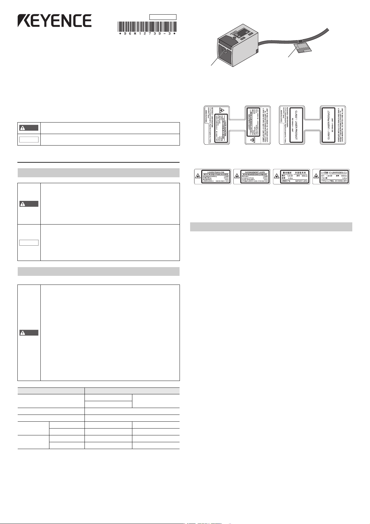
Laser emission
point
Laser warning and
explanation label
Class 2 (English) Class1
Class 2 (included with the product in each language)
96M12739
All-Purpose Laser Sensor
LR-TB5000 Series
Instruction Manual
Read this manual before using the product in order to achieve maximum performance.
Keep this manual in a safe place after reading it so that it can be used at any time.
The following symbols alert you to important messages. Be sure to read these
messages carefully.
It indicates a hazardous situation which, if not avoided, could result in
death or serious injury.
It indicates a situation which, if not avoided, could result in product
damage as well as property damage.
Laser warning and explanation labels
XX-XXXX
1567
1
1234
2
MODE
DISP
z Laser warning and explanation labels
• Attached to the cable
1 Introduction
Safety Information for LR-TB Series
• This product is only intended to detect object(s). Do not use this
product for the purpose to protect a human body or part of a human
body.
• This product is not intended for use as an explosion-proof product.
Do not use this product in a hazardous location and/or potentially
explosive atmosphere.
• This product uses DC power. The product may explode or burn if an
AC voltage is applied.
• Do not wire the cable along with power lines or high-tension lines,
as the sensor may malfunction or be damaged due to noise.
• When using a commercially available switching regulator, ground
the frame ground terminal and ground terminal.
• Do not use this product outdoors or in a location in which its
light-receiving surface will come in direct contact with stray ambient
light.
Safety Precautions on Laser Product
This product uses a semiconductor laser as its light source.
• Use of controls or adjustments or performance of procedures other
than those specified herein may result in hazardous radiation
exposure.
• Follow the instructions mentioned in this manual. Otherwise, injury
to the human body (eyes and skin) may result.
• Laser emission from this product is not automatically stopped when
it is disassembled. Do not disassemble this product.
• Precautions on Class 2 Laser Product
- Do not stare into the direct or specularly reflected beam.
- Do not direct the beam at people or into areas where people
might be present.
- Be careful of the path of the laser beam.
If there is a possibility that the operator may be exposed to the
specular or diffuse reflections, block the beam by installing a
protective enclosure.
- Install this product so that the path of the laser beam is not as the
same height as that of human eye.
• Precautions on Class 1 Laser Product
- Do not stare into the direct or specularly reflected beam.
Item Description
Model
Wavelength 660 nm
Pulse width 4.3 ns
FDA(CDRH)
Part1040.10
JIS C 6802/
IEC 60825-1
* The laser classification for FDA (CDRH) is implemented based on IEC60825-1 in
accordance with the requirements of Laser Notice No.50.
Laser class* Class 2 laser product Class 1 laser product
Output 1.0 mW 390 μW
Laser class Class 2 laser product Class 1 laser product
Output 1.0 mW 390 μW
LR-TB5000
LR-TB5000C
LR-TB5000CL
• Included with the product
* For a Class 2 laser product, select from the warning and explanation labels included
in the package the appropriate warning and explanation label according to the country and region where the Class 2 laser product will be used. Then, affix the warning
and explanation label over top of the existing warning and explanation label on the
product.
Precautions on Regulations and Standards
CSA Certificate
LR-TB series complies with the following CSA and UL standards and has been certified by
CSA (Class 2252 06 / Class 2252 86).
• Applicable standard: CAN/CSA C22.2 No.61010-1
• Use the following power supply.
CSA/UL certified power supply that provides Class 2 output as defined in the CEC
(Canadian Electrical Code) and NEC (National Electrical Code), or CSA/UL certified power
supply that has been evaluated as a Limited Power Source as defined in CAN/ CSA-C22.2
No. 60950-1/UL60950-1
• Use this product at the altitude of 2000 m or less.
• Use this product at the level of overvoltage category I.
• Use this product at pollution degree 3.
• Indoor use only.
CE Marking
Keyence Corporation has confirmed that this product complies with the essential
requirements of the applicable EC Directive, based on the following specifications.
Be sure to consider the following specifications when using this product in a member state
of the European Union.
z EMC Directive (2004/108/EC)
• Applicable standard EMI : EN60947-5-2, Class A
z Low-voltage Directive (2006/95/EC)
• Applicable standard: EN61010-1, EN60825-1
• Use the power supply that has been evaluated as a Limited Power Source as defined in
IEC60950-1/EN60950-1.
• Use this product at the altitude of 2000 m or less.
• Use this product at the level of overvoltage category I.
• Use this product at pollution degree 3.
• Indoor use only
Remarks: These specifications do not give any guarantee that the end-product with this
product incorporated complies with the essential requirements of the EMC
Directive.
The manufacturer of the end-product is solely responsible for the compliance of
the end-product itself according to the EMC Directive.
UL61010-1
EMS : EN60947-5-2
1
Page 2
Package Contents
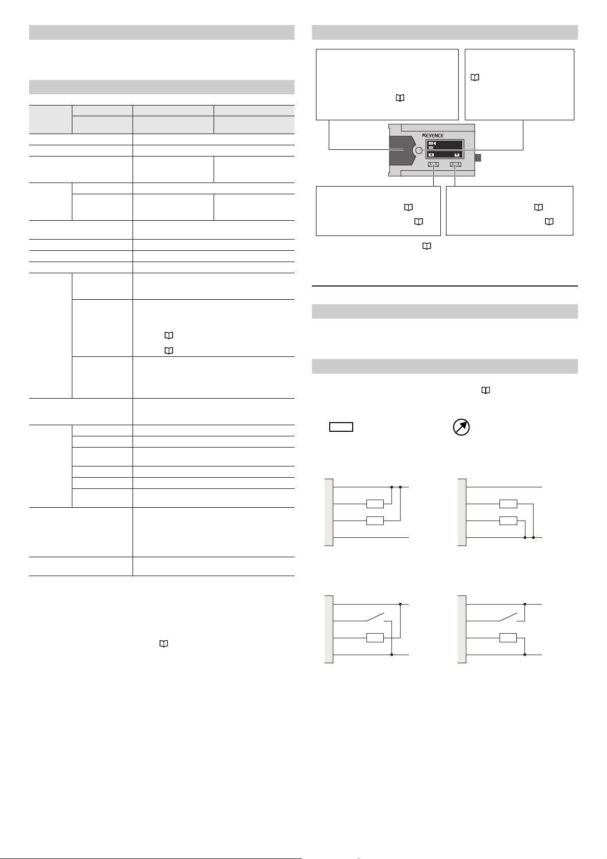
Indicator
Output 1 ON : Orange*
Output 1 OFF: Green*
Error : Flashing red
* The indicator flashes when two conditions below
are met;
• Stability output tur ns ON ( page 10).
• Output 1 turns OFF when output logic is N.O. or
turns ON when output logic is N.C.
[SET] Button
The operation of this button varies
depending on the detection mode
( page 5).
Example: 2-point calibration
1. Press this button with no workpiece
present.
2. Press this button with a workpiece
present.
[DISP/S] Button
Pressed for 1 second or less:
Changes the setting value ( page 7)
Held for 3 seconds or more:
Switches to the display screen ( page
8)
[MODE/T] Button
Pressed for 1 second or less:
Changes the setting value ( page 7)
Held for 3 seconds or more:
Switches to the setting screen ( page
9)
Load (input device)
Analog current or voltage input device
1, brown
4, black
2, white
3, blue
20 ... 30 V
0 V
1, brown
4, black
2, white
3, blue
20 ... 30 V
0 V
1, brown
4, black
2, white
3, blue
20 ... 30 V
0 V
1, brown
4, black
2, white
3, blue
20 ... 30 V
0 V
• Main unit
• Instruction manual
• Laser warning and explanation labels (LR-TB5000/LR-TB5000C only)
Specifications
Part Functions
Model
Detectable distance
Spot diameter Variable (use a spot diameter of 40 mm or less)
Response time
Light source
Mutual interference prevention
function
Timer OFF/OFF delay/ON delay/One-shot
Power voltage 20 to 30 VDC, including 10% ripple (P-P), Class 2 or LPS
Current consumption 50 mA or less (without load)
*4*5
I/O
Protection circuit
Environmental
resistance
Material
Weight
Cable
Cable with
connector M12
*1
Type Red laser (660 nm)
Laser class
Control output
External input
Analog output
Enclosure rating IP65/IP67 (IEC60529)
Ambient light Incandescent lamp/Sunlight: 100000 lux or less
Ambient
temperature
Ambient humidity 35 to 85%RH (no condensation)
Shock resistance 1000m/s2 in X, Y, Z axis directions respectively 6 times
Vibration resistance
LR-TB5000 -
LR-TB5000C LR-TB5000CL
60 to 5000 mm
1 ms/10 ms/25 ms/
100 ms/1000 ms
selectable
Class 2 laser product
IEC60825-1,FDA(CDRH)
Part1040.10
4 units (when using the interference prevention function)
NPN open collector/PNP open collector selectable
Residual voltage: 2 V or less, N.O./N.C. selectable
Short-circuit current: 1 mA or less for both NPN and PNP
For the applied voltage, see the wiring diagrams
Current output: 4 to 20 mA with a max. load resistance
Voltage output: 0 to 10 V with an external load resistance
Protection against reverse power connection,
power supply surges, output overcurrent, output surge,
10 to 55 Hz Double amplitude 1.5 mm in the X, Y, Z axis
Case: Zinc die cast (Nickel chrome plating), I
and buttons: PES, Lens cover and display: PMMA
M12 connector (only for the cable with connector M12 type):
Cable type: Approx. 200 g (Including cable)
Cable with connector M12 type: Approx. 160 g
*2
30 VDC or less, 50 mA or less,
Transmission OFF / Tuning /
Reference surface update selectable
( page 2 in the instruction manual).
For the input times, see the time charts
( page 4 in the instruction manual).
Current output / Voltage output selectable
of 5 kΩ or more
and reverse output connection
-20 to +55°C (no freezing)
directions respectively, 2 hours
(scratch-resistant coating specifications),
Cable bushing: PBT, Cable: PVC,
TPE, PBT, Nickel-plated brass
2 ms/20 ms/50 ms/
200 ms/2000 ms
Class 1 laser product
IEC60825-1,FDA(CDRH)
Part1040.10
of 500 Ω
*1 The range for displayable distance is from 50 to 5200.
*2 The laser classification for FDA (CDRH) is implemented based on IEC60825-1 in
accordance with the requirements of Laser Notice No.50.
*3 150mA or less (with load)
*4 You can select the I/O from the following combinations.
Control output × 2, control output + external input, control output + analog output,
external input + analog output
(For details on the setting method, see page 3 of the instruction manual.)
*5 IO-Link specification v.1.1/COM2 (38.4 kbps) is supported.
You can download a setup file from the KEYENCE website (http://www.keyence.com).
If you are using the product in an environment in which you cannot download files
over the Internet, contact your nearest KEYENCE office.
selectable
*3
ndicator cover
XX-XXXX
1
2
1567
1234
DISP MODE
*2
For a more detailed explanation, see "Switching between Display Screens" (page 8).
2 Installation and Wiring
Installation
• Tightening torque for the mounting holes: 1.5 N·m (M4 screw)
• If the detecting object has a mirrored surface, install the sensor in a position where
specular reflection will not penetrate the optical receiver.
Wiring
With the LR-TB Series, you can select the functions of the I/O wires (black and white) from
the combinations shown below during the initial settings. "3 Initial Settings" (page 3)
Independently isolate any I/O wires that you will not use.
Out1+Out2
z NPN z PNP
Input+Out1
z NPN z PNP
2
Page 3
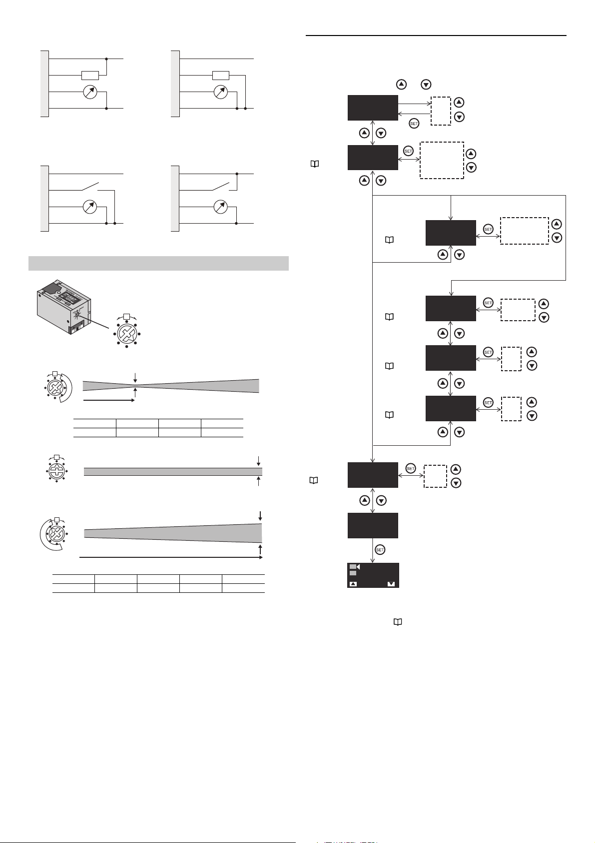
Out1+Analog
1, brown
4, black
2, white
3, blue
20 ... 30 V
0 V
1, brown
4, black
2, white
3, blue
20 ... 30 V
0 V
1, brown
4, black
2, white
3, blue
20 ... 30 V
0 V
1, brown
4, black
2, white
3, blue
20 ... 30 V
0 V
1
2
3
4
5
6
7
8
WIDE
NARROW
Use the dial on the back of the sensor
to adjust the spot diameter.
1
2
3
4
5
6
7
8
WIDE
NARROW
0X mm
Diameter of approx. 6 mm
1
2
3
4
5
6
7
8
WIDE
NARROW
0 X mm
Diameter of approx. 40 mm
3-1. I/O
Selection
( page 4)
3-2. External
Input Selection
( page 4)
3-5. NPN/PNP
Selection
( page 4)
3-3. Analog
Selection
( page 4)
3-4. Analog
Lower Limit
( page 4)
3-4. Analog
Upper Limit
( page 4)
z NPN z PNP
3 Initial Settings
When you turn on the LR-TB Series for the first time after you purchase it or when you have
initialized the LR-TB Series, the following initial settings must be configured.
Display Units
and
Press for 3 seconds or more
Input+Analog
z NPN z PNP
Adjusting the Spot Diameter
Narrow Spot Setting
NARROW 1 2 3
X (Approx.) 500 1000 2000
Parallel Light Setting
WIDE
NARROW
4
3
5
6
7
1
8
2
Start Config.
Select I/O
Out1+Out2
Out1+Out2
Select Output
NPN
Input+Out1
mm
inch
feet
Out1+Out2
Input+Out1
Out1+Analog
Input+Analog
Select Input
Laser Off
Select Analog
4 - 20 mA
Analog Scaling
4 mA = 0
Analog Scaling
20 mA = 5000
NPN
PNP
Out1+Analog or Input+Analog
Laser Off
Tuning
DATUM Preset
4 - 20 mA
0 - 10V
9999
...
0
9999
...
0
Wide Spot Setting
WIDE5678
X (Approx.) 5000 3000 1500 750
• When detecting objects that have holes in them, you can perform stable detection by
making the spot diameter larger.
• Set the spot diameter so that it is 40 mm or less at the desired detecting distance.
End Config.
1
2
1234
500
•
After you have finished configuring the initial settings, you will not be able to reconfigure the
unit, I/O, analog selection, or NPN/PNP selection. To change any of these settings, you will
RUN
have to initialize the product . "Initialization" (page 8).
3
Page 4
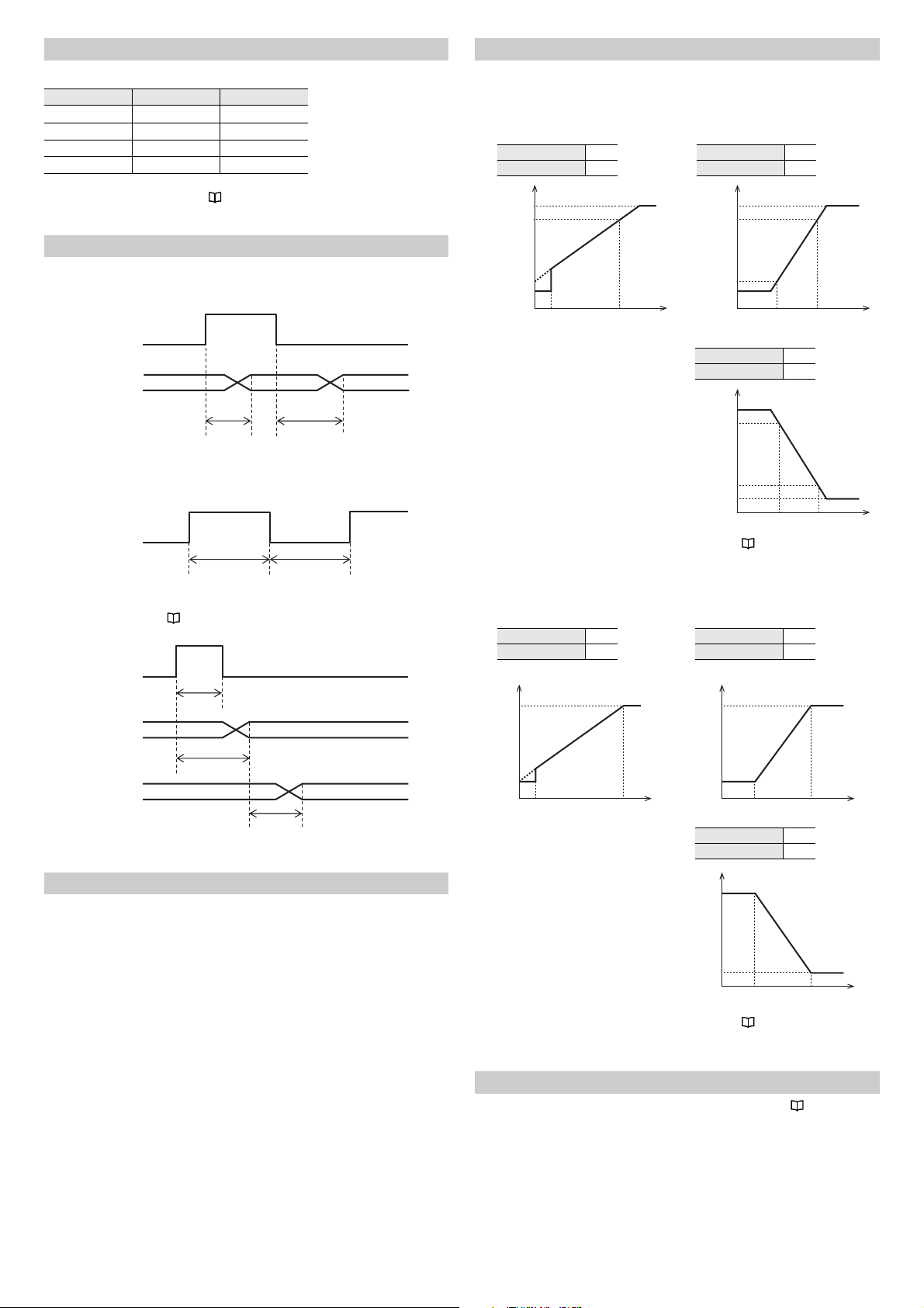
3-1. I/O Selection
Input
ON
> 60 ms
> 60 ms
OFF
Updated reference surface
Updated output
Input
ON
> 5 ms
< 60 ms
Response
time
OFF
Analog 4 mA 0
Analog 20 mA 5000
Analog 4 mA 4000
Analog 20 mA 2000
Analog 4 mA 2000
Analog 20 mA 4000
10 V
0 50 5000
0 V
10 V
0 2000 4000
0 V
10 V
0 2000 4000
0 V
Analog 0V
2000
Analog 10V
4000
Analog 0V
4000
Analog 10V
2000
Analog 0V
0
Analog 10V
5000
Select from the following table the functions assigned to the I/O wires (black and white).
Options Black Wire White Wire
Out1 + Out2 Output 1 Output 2
Input + Out1 External input Output 1
Out1 + Analog Output 1 Analog output
Input + Analog External input* Analog output
The functions assigned to output 1, output 2, and external input can be changed after you
finish configuring the initial settings. "6 Detailed Settings" (page 9).
* Would be fixed to transmission OFF.
3-2. External Input Selection
Transmission OFF [Laser Off]
The laser beam transmission is stopped.
ON
Input
OFF
Transmission TransmissionOFF
< 5 ms < 50 ms
External Calibration [Tuning]
When selected, this external input performs the same function as pressing the [SET]
button.
3-4. Analog Lower and Upper Limits
Configure scaling settings, if necessary.
Current output (4 to 20 mA)
z Initial settings z When settings are changed
20.5 mA
20 mA
4 mA
3.8 mA
0 50 5000
(example)
20.5 mA
20 mA
4 mA
3.8 mA
0 2000 4000
20.5 mA
20 mA
4 mA
3.8 mA
Reference surface update [DATUM Preset]
When the detection mode ( "4 Detection Mode" [page 5]) is set to "DATUM mode," this
external input updates the reference surface.
3-3. Analog Selection
Select from the following values.
• Current output: 4 to 20 mA
• Voltage output: 0 to 10 V
0 2000 4000
For details on the analog output when an error occurs, see " Output When an Error
Occurs" (page 11).
■
Voltage output (0 to 10V)
●
Initial settings
●
When settings are changed
(example)
For details on the analog output when an error occurs, see " Output When an Error
Occurs" (page 11).
3-5. NPN/PNP Selection
You can select between NPN outputs or PNP outputs. For details, see "Wiring" (page
2).
4
Page 5

4 Detection Mode
1567
1234
XX-XXXX
DISP MODE
1
2
A-A
0
ON
ON
N.O.
N.C.
OFF
OFF
Hys.
Hys.
A: Setting value
Hys: Hysteresis ( page 11)
Reference surface
1567
1234
XX-XXXX
DISP MODE
1
2
1567
1234
XX-XXXX
DISP MODE
1
2
ON
A
-A
ON
N.O.
N.C.
OFF
OFF
1
2
Reference surface
Press the set button for 1 second or less.
Press and hold the set button for 3 seconds or more.
Completion
1567
1234
XX-XXXX
DISP MODE
1
2
Hys.
ON
ON
A
0
5000
N.O.
N.C.
OFF
OFF
A: Setting value
Hys: Hysteresis ( page 11)
1567
1234
XX-XXXX
DISP MODE
1
2
1
2
1567
1234
XX-XXXX
DISP MODE
1
2
1567
1234
XX-XXXX
DISP MODE
1
2
ON
ON
N.O.
N.C.
OFF
OFF
Press the set button for 1 second or less.
Setting value
Press the set button for 1 second or less.
Completion
The LR-TB Series has four output modes and three detection modes.
Output Mode ( page 10) Detection Mode
Standard (default value) [Standard]
Window [Window] 4-3. Window mode
Stability [Stability] ( page 10)
Error [Error] ( page 10)
When the output modes for Out1 & Out2 are either [Standard] or [Window], the detection
modes can only be set in the below combinations.
[Out1] / [Out2] = [DATUM]/ [DATUM], [Distance]/ [Distance], [Distance]/ [Window],
[Window]/ [Distance], [Window]/ [Window]
4-1. DATUM Mode (FGS)
Operation
• In this mode, the change in position from a reference surface (which has a value of 0) is
displayed.
• This mode is useful in detecting the passage of workpieces in front of a stationary
background.
4-1. DATUM mode (FGS)
4-2. Distance mode (BGS)
4-2. Distance Mode (BGS)
Operation
• In this mode, the distance from the sensor is displayed.
Setting
• Set the detection mode to [Standard], which is the default value. "6 Detailed
Settings" (page 9)
• For details on setting output 2, see " 4-5. Switching Out1/Out2" (page 7)
z
2-point calibration
Setting
• Set the output mode to [Standard], which is the default mode. "6 Detailed Settings"
(page 9)
• For details on setting output 2, see " 4-5. Switching Out1/Out2" (page 7).
• In DATUM mode, a "±" is displayed in front of the setting value.
5
Page 6

z
1567
1234
XX-XXXX
DISP MODE
1
2
1
2
1567
1234
XX-XXXX
DISP MODE
1
2
1567
1234
XX-XXXX
DISP MODE
1
2
N.O.
N.C.
ON
OFF
ON
OFF
Press and hold the set button
for 3 seconds or more.
Completion
Press and hold the set button
for 3 seconds or more.
The object is detected while
the button is pressed.
1
N.O.
N.C.
1567
1234
XX-XXXX
DISP MODE
1
2
ON
OFF
ON
OFF
1567
1234
XX-XXXX
DISP MODE
1
2
Press and hold the set button
for 3 seconds or more.
Completion
Hys: Hysteresis ( page 11)
Completion
Press the set button for 1 second or less.
Press the set button for 1 second or less.
Full auto calibration
Use this function when the movement of detected objects cannot be stopped.
4-3. Window Mode
Operation
• In this mode, the distance from the sensor is displayed.
• You can assign setting values to the upper and lower limits
5000
ON
N.O.
OFF
ON
N.C.
OFF
Hys. Hys.
Setting
• Set the detection mode to [Window]. "6 Detailed Settings" (page 9)
• For details on setting output 2, see " 4-5. Switching Out1/Out2" (page 7).
z
2-point calibration
Use this function to detect objects inside a range of specific upper and lower limits.
NEARFAR
0
XX-XXXX
1
2
1567
1234
DISP MODE
1
XX-XXXX
1
2
1567
1234
DISP MODE
z
1-point calibration
Use this function to enable the installation of detected objects at the upper limit that you
do not want to detect.
2
XX-XXXX
1
2
1567
1234
DISP MODE
NEARFAR
XX-XXXX
1
2
1567
1234
N.O.
N.C.
ON
OFF
ON
OFF
DISP MODE
6
Page 7

z
Press and hold the set button for 3 seconds or more.
Completion
RUN
1567
1234
XX-XXXX
DISP MODE
1
2
1...9999
1567
1234
1
2
1567
1234
1
2
Press the [DISP/S] or the [MODE/T] button
(for 1 second or less).
3 seconds
XX-XXXX
DISP MODE
RUN
FAR
NEAR
1...9999
1567
1234
1789
1
2
N
N
F
1567
1234
1789
1
2
F
N
F
1567
1234
1789
1
2
N
F
1567
1234
1789
1
2
N
F
Press the [DISP/S] or the [MODE/T] button
(for 1 second or less).
3 seconds 3 seconds
Press the [DISP/S] or the [MODE/T] button
(for 1 second or less).
3 seconds
3 seconds 3 seconds
1567
1234
XX-XXXX
DISP MODE
1
2
1567
1234
1
2
Out2 1456
S
Out1 1234
Out1 1234
Out2 1456
S
1567
1456
1
2
1567
1456
1
2
RUN
1567
1234
1
2
RUN
Press the [DISP/S] or the [MODE/T] button
(for 1 second or less).
An arrow will be displayed next to the setting value to be changed when tuning
or calibration is implemented.
3 seconds 3 seconds
1-point calibration
Use this function when you cannot move detected objects away from the center of the
detection range.
1
XX-XXXX
1
2
1567
1234
DISP MODE
When [Out2] mode is set to [Standard] or [Window]
XX-XXXX
1
2
1567
1234
DISP MODE
FAR
ON
N.O.
OFF
ON
N.C.
OFF
4-4. Manual Tuning
NEAR
DISP MODE
S
Out1 1234
Out2 1456
S
Out1 1234
Out2 1456
[Standard]
1
1567
2
F
N
F
1567
1234
1789
[Window]
1234
1789
1...9999
RUNRUN
[Standard]
XX-XXXX
1
2
1567
1234
1
2
1567
1
2
1567
1234
1234
1
2
N
1...9999
1567
1234
N
F
1789
FARNEAR
1
2
N
F
4-5. Switching Out1/Out2
The initial [Out2] mode is [Stability]. "6 Detailed Settings" (page 9)
When [Out2] mode is set to [Standard] or [Window], the setting below could be
manipulated.
When the detection mode is set to [Window]
7
Page 8

5 Useful Functions
9999
Input Password
0000
0000
...
1567
1234
XX-XXXX
DISP MODE
1
2
1567
1234
XX-XXXX
DISP MODE
1
2
Press these buttons at the same time for 3 seconds or more.
If necessary, enter the password to release the lock.
Lock Unlock
1567
1234
XX-XXXX
DISP MODE
1
2
Initialize ?
No
Initialize ?
Yes
While pressing the [MODE/T] button, press the [SET]
button five times.
"3 Initial Settings" (page 3)
Use the I/O selection to change what is displayed here. " 3-1. I/O Selection" (page 4).
(1): Output 1 (displayed in gray when OFF)
(2): Output 2 (displayed in gray when OFF)
A: Current output
V: Voltage output
IN: External input (displayed in gray when OFF)
An arrow will be displayed next to the setting value to be changed
when tuning or calibration is implemented.
Current value
Setting value
(the display of which
can be changed)
The indicator will turn grey while the
[DISP /S] button is pressed.
The indicator will turn grey while the
[MODE /T] button is pressed.
1567
1234
XX-XXXX
DISP MODE
1
2
1567
1234
1
2
1567
1234
1789
1
2
P
B
1567
1
2
Simple
Display
S
Bar
Display
S
Peak Bottom
Display
S
Standard
Display
S
1567
MIN
1
2
MAX
Press the [DISP /S] button
(for 3 seconds or more).
Current value
Setting value
Current value
Peak val ue*
Bottom value*
Current value
Bar
Current value
Key Lock
To require a password to release the key lock, see " 6-13. Password" (page 11).
Switching between Display Screens
You can select between four different displays.
Display screen
1
2
1234
1789
How to switch the display
Initialization
Initialization resets the product to its factory default settings. After initialization, you will
have to configure the "3 Initial Settings" (page 3).
Using the shortcut keys to execute the initialization
Using the setting menu to execute the initialization
On the "Initialize?" screen, select "Yes". "6 Detailed Settings" (page 9)
* When the output changes from ON to OFF, the bottom value is reset to the current
value.
When the output changes from OFF to ON, the peak value is reset to the current
value.
When the analog output [Analog] is selected, pressing [DISP/
S] or [MODE/T] resets
both the bottom value and the peak value to the current value.
8
Page 9

6 Detailed Settings
1000 ms
N.O.
N.C.
(Stability) *2
(Error) *2
Window
Off-delay
On-delay
One shot
9999 ms
1 ms
...
Off
Standard
Standard
Custom
Custom
Standard
Window
Stability
Error
Off
Off-delay
On-delay
One shot
Channel 4
Channel 3
Channel 2
Channel 1
High
Mid
Low
Laser Off
Tuning
DATUM Preset
Menu
Response Time
25 ms
Output1 Logic
N.O.
Output2 Logic
N.O.
Output2 Mode
Stability
Output1 Mode
Standard
Hysteresis
Standard
Hys.Value
10
Sensitivity
High
Analog Scaling
4 mA = 0
Analog Scaling
20 mA = 5000
Analog Test
Off
Output1 Timer
Off
Output2 Timer
Off
Adv. Settings
Off
End
End
Timer1 Setting
10 ms
100 ms
25 ms
10 ms
1 ms
4567
2345
1
2
*1
Off
Off
Timer2 Setting
10 ms
4567
2345
1
2
4567
2345
1
2
N.O.
N.C.
Off
On
Off
On
Off
On
100%
30%
Display Off
Off
On
On
On
On
RUN
RUN
9999 ms
1 ms
...
9999
0000
No
Yes
...
9999
0
...
20.0 mA
4.0 mA
...
9999
0
...
9999
0
...
Test Value
4.0 mA
Output Hold
Off
Brightness
30%
Interference
Channel1
Password Lock
Off
Enter Password
0000
Initialize?
No
B
B
A
A
C
D
Out1+Out2
B
Input+Out1
C
Out1+Analog
D
Input+Analog
Stability or Error
Stability or Error
Input Function
Laser Off
D
3-1. I/O Selection
( page 4)
6-1. Response Time
( page 10)
6-3. Output 1 Mode
( page 10)
6-4. Output 1 Timer
( page 10)
6-2. Output 2 Logic
( page 10)
6-3. Output 2 Mode
( page 10)
6-4. Output 2 Timer
( page 10)
6-5. Hysteresis
( page 11)
6-14.
Initialization
( page 11)
6-6. Received
Light Sensitivity
( page 11)
6-9. Input
Function
( page 11)
You can complete settings by holding down the
button.
3 seconds
Advanced Settings
6-2. Output 1 Logic
( page 10)
6-13. Password
( page 11)
6-12.
Interference
Prevention
( page 11)
6-11. Screen
Brightness
( page 11)
6-10. Output
Hold
( page 11)
6-7. Analog
Upper Limit
( page 11)
6-7. Analog
Lower Limitt
( page 11)
6-8. Analog
Output Test
( page 11)
The values shown on the display screen are the initial values.
*1 The LR-TB5000CL has the following response times.
2000 ms
200 ms
50 ms
20 ms
2 ms
*2 Only when the I/O selection ( " 3-1. I/O Selection" [page 4]) is [Out1 + Analog]
9
Page 10

A
ON
OFF
ON
N.O.
N.C.
FAR
NEAR
OFF
ON
OFF
ON
N.O.
N.C.
OFF
ON
OFF
ON
N.O.
N.C.
OFF
ON
OFF
ON
N.O.
N.C.
OFF
Timer OFF
Off Delay
On Delay
One Shot
Timer time
6-1. Response Time
Longer response times lead to more stable detection.
LR-TB5000/LR-TB5000C
Example) Chart during DATUM mode
XX-XXXX
1234
1567
2
1
DISP MODE
Detecting
distance
[mm]
White Paper (Reflectivity: 90%)
Response Time[ms]
1 10 25 100 1000
1000±7±3±3±3±3
5000 ±42 ±12 ±9 ±5 ±3
Repetition Accuracy [mm] (Typical) (Under stable temperature)
Repetition Accuracy [mm] (Typical) (Under stable temperature)
Detecting
distance
[mm]
Gray Paper (Reflectivity: 18%)
Response Time[ms]
1 10 25 100 1000
1000 ±11 ±4 ±3 ±3 ±3
5000 ±154 ±40 ±29 ±14 ±6
LR-TB5000CL
Detecting
distance
[mm]
1000±9±6±6±3±3
5000 ±42 ±14 ±10 ±5 ±5
Detecting
distance
[mm]
1000 ±12 ±6 ±4 ±3 ±3
5000 ±159 ±42 ±31 ±15 ±8
Repetition Accuracy [mm] (Typical) (Under stable temperature)
White Paper (Reflectivity: 90%)
Response Time[ms]
2 20 50 200 2000
Repetition Accuracy [mm] (Typical) (Under stable temperature)
Gray Paper (Reflectivity: 18%)
Response Time[ms]
2 20 50 200 2000
NEAR
Distance
mount of
received light
(workpiece
background)
Stability
output
(N.O.)
FAR
OFF
ON
5 cycles
Setting value
Amount of
received light
threshold (fixed)
z When the I/O selection is [Analog]
Output is generated if the amount of light received falls below the threshold (fixed
value) for 5 seconds or more.
Error [Error]
Output is activated when an error occurs. When the error is cleared, the output is also
automatically reset. For causes of errors, see " Error Display" (page 11).
6-4. Timer
This function can be used to delay the timing with which the sensor output is switched.
• Off delay [Off-delay]
• On delay [On-delay]
• One shot [One shot]
6-2. Output Logic
Select N.O. or N.C. for the output logic. For details, see "4 Detection Mode" (page 5).
6-3. Output Mode
Standard [Standard]
The output is activated according to the detecting distance. For details, see "4 Detection
Mode" (page 5).
Window [Window]
The output is activated according to the detecting distance. For details, see " 4-3.
Window Mode" (page 6).
Stability [Stability]
This function can be used to check whether there has been a decrease in the amount of
light received due to problems such as dirt on the detected surface.
z When the I/O selection is [Out1 + Out2]
Output is activated if the amount of light received falls below the threshold (fixed value)
during the observation period.
Detection Mode Observation Period
DATUM
Distance Detected value < setting value
Window
Negative setting value < detected value
< positive setting value
LOW-side setting value < detected value
< HIGH-side setting value
10
Page 11

6-5. Hysteresis
FAR
NEAR
ON
OFF
ON
N.O.
N.C.
OFF
Hysteresis
Setting value
B
1000 2000
A
Hysteresis
Detecting
distance
Unit: mm
Response Time (ms) A(mm) B(mm)
25 to 2000 15 20
10, 20 30 40
1, 2 60 80
NEAR
00
ON
N.O.
)
OFF
NEAR
ON
(
N.O.
)
OFF
Display Display
Distance
display
Distance
display
SettingSetting
DistanceDistance
Output Output
Hysteresis is the difference between the value at which the output turns ON and the value
at which the output turns OFF.
• With [Standard], the hysteresis varies depending on the response time and the
detecting distance.
6-11. Screen Brightness
You can set the operation to perform when no button operations are performed for a set
length of time.
Item Description
100% The display brightness is always kept at 100%.
30% (default value)
Display Off After a certain length of time elapses, the display is turned OFF.
After a certain length of time elapses, the display brightness is set to
30%.
• If you use the LR-TB Series for a long period of time, the display brightness will
decrease.
• If you set this to [100%], the display brightness will decrease at a faster rate.
6-12. Interference Prevention
With the LR-TB Series, you can prevent the effect of mutual interference by changing the
laser emission channel. If you are using multiple LR-TB Series units in close proximity to
each other, set each one to have a different laser emission channel.
6-13. Password
If you set this to [ON], you can set a personal identification number that must be entered to
release the " Key Lock" (page 8). You can set the personal identification number to a
value from 0 to 9999.
• With [Custom], you can specify an arbitrary value regardless of the detecting distance.
• For details on the operation differences between the detection modes, see "4
Detection Mode" (page 5).
6-6. Received Light Sensitivity
By lowering the received light sensitivity level, you can reduce the number of times that
malfunctions such as the following occur.
• Detections of dirt and mist between the sensor and the detected object.
• Detections of translucent objects when passing through translucent objects to detect
the target.
You cannot change the received light sensitivity when " 6-1. Response Time" (page 10)
is set to [1ms/10ms]/[2ms/20ms].
6-7. Analog Lower and Upper Limits
For details, see "3-4. Analog Lower and Upper Limits" (page 4).
6-8. Analog Output Test
You can output arbitrary currents and voltages.
6-9. Input Function
For details, see " 3-2. Exter nal Input Selection" (page 4).
6-10. Output Hold
This function holds the display value and the output status that were in use immediately
prior to the LR-TB Series becoming unable to receive light.
When Output Hold is OFF When Output Hold is ON
6-14. Initialization
Initialize the sensor settings. You can also use the shortcut keys to execute the
initialization. "Initialization" (page 8)
After initialization, you will have to configure the "3 Initial Settings" (page 3).
7Other
Error Display
Error Display Cause and Remedy
NEAR*
- - - -*
Over Current
Laser Error
EEPROM Error
System Error
* When Output mode is set to [Error], while “Near” or “- - - -” is on display, the output would not
switch.
Output When an Error Occurs
The detected object is not within the detectable range (the detected
object is too close).
Light reflected from the detected object could not be received.
• The amount of light received from the detected object is low.
• The detected object is not within the detectable range of the LR-TB (the
detected object is too far away).
An overcurrent is flowing through the output wire.
• Check whether the output wire is connected correctly.
• Check whether the output wire is in contact with other wires.
A laser diode error has occurred.
• If you cannot fix the problem by restarting the product, the product must
be replaced.
1) Settings have been rewritten more than 1,000,000 times.
• The memory has reached the end of its service life.
2) A recording memory error has occurred.
• If you cannot fix the problem by restarting the product, the product must
be replaced.
An internal system error has occurred.
• If you cannot fix the problem by restarting the product, the product must
be replaced.
Error Display
NEAR ON OFF 3.8 0
- - - - OFF ON 20.5 10
Over Current
Laser Error
EEPROM Error
System Error
*1 When Output mode is set to [Error], despite the setting of N.O. or N.C., LR-T would remain
*2 When Output mode is set to [Error], LR-T would turn ON with N.O. and turn OFF with N.C.
*1
*2
*2
*2
OFF to protect the output circuit.
Output ON or OFF Analog Output
N.O. N.C. 4 to 20 mA
OFF OFF
OFF ON 2 0
The same as during normal operation
OFF ON 2 0
The same as during normal
0 to 10 V
operation
11
Page 12

WARRANTIES AND DISCLAIMERS
(1) KEYENCE warrants the Products to be free of defects in materials and
workmanship for a period of one (1) year from the date of shipment. If any models
or samples were shown to Buyer, such models or samples were used merely to
illustrate the general type and quality of the Products and not to represent that
the Products would necessarily conform to said models or samples. Any
Products found to be defective must be shipped to KEYENCE with all shipping
costs paid by Buyer or offered to KEYENCE for inspection and examination.
Upon examination by KEYENCE, KEYENCE, at its sole option, will refund the
purchase price of, or repair or replace at no charge any Products found to be
defective. This warranty does not apply to any defects resulting from any action of
Buyer, including but not limited to improper installation, improper interfacing,
improper repair, unauthorized modification, misapplication and mishandling, such
as exposure to excessive current, heat, coldness, moisture, vibration or outdoors
air. Components which wear are not warranted.
(2) KEYENCE is pleased to offer suggestions on the use of its various Products.
They are only suggestions, and it is Buyer's responsibility to ascertain the fitness
of the Products for Buyer’s intended use. KEYENCE will not be responsible for
any damages that may result from the use of the Products.
(3) The Products and any samples ("Products/Samples") supplied to Buyer are not to
be used internally in humans, for human transportation, as safety devices or
fail-safe systems, unless their written specifications state otherwise. Should any
Products/Samples be used in such a manner or misused in any way, KEYENCE
assumes no responsibility, and additionally Buyer will indemnify KEYENCE and
hold KEYENCE harmless from any liability or damage whatsoever arising out of
any misuse of the Products/Samples.
(4) OTHER THAN AS STATED HEREIN, THE PRODUCTS/SAMPLES ARE
PROVIDED WITH NO OTHER WARRANTIES WHATSOEVER. ALL EXPRESS,
IMPLIED, AND STATUTORY WARRANTIES, INCLUDING, WITHOUT
LIMITATION, THE WARRANTIES OF MERCHANTABILITY, FITNESS FOR A
PARTICULAR PURPOSE, AND NON-INFRINGEMENT OF PROPRIETARY
RIGHTS, ARE EXPRESSLY DISCLAIMED.
IN NO EVENT SHALL KEYENCE AND ITS AFFILIATED ENTITIES BE LIABLE
TO ANY PERSON OR ENTITY FOR ANY DIRECT, INDIRECT, INCIDENTAL,
PUNITIVE, SPECIAL OR CONSEQUENTIAL DAMAGES (INCLUDING,
WITHOUT LIMITATION, ANY DAMAGES RESULTING FROM LOSS OF USE,
BUSINESS INTERRUPTION, LOSS OF INFORMATION, LOSS OR
INACCURACY OF DATA, LOSS OF PROFITS, LOSS OF SAVINGS, THE COST
OF PROCUREMENT OF SUBSTITUTED GOODS, SERVICES OR
TECHNOLOGIES, OR FOR ANY MATTER ARISING OUT OF OR IN
CONNECTION WITH THE USE OR INABILITY TO USE THE PRODUCTS,
EVEN IF KEYENCE OR ONE OF ITS AFFILIATED ENTITIES WAS ADVISED
OF A POSSIBLE THIRD PARTY’S CLAIM FOR DAMAGES OR ANY OTHER
CLAIM AGAINST BUYER. In some jurisdictions, some of the foregoing warranty
disclaimers or damage limitations may not apply.
BUYER'S TRANSFER OBLIGATIONS:
If the Products/Samples purchased by Buyer are to be resold or delivered to a
third party, Buyer must provide such third party with a copy of this document, all
specifications, manuals, catalogs, leaflets and written information provided to
Buyer pertaining to the Products/Samples.
KEYENCE CORPORATION
1-3-14, Higashi-Nakajima, Higashi-Yodogawa-ku,
Osaka, 533-8555, Japan
PHONE: +81-6-6379-2211
AUSTRIA
Ph: +43 22 36-3782 66-0
BELGIUM
Ph: +32 1 528 1222
BRAZIL
Ph: +55-11-3045-4011
CANADA
Ph: +1-905-366-7655
CHINA
Ph: +86-21-68757500
CZECH REPUBLIC
Ph: +420 222 191 483
FRANCE
Ph: +33 1 56 37 78 00
GERMANY
Ph: +49 6102 36 89-0
Specifications are subject to change without notice.
Copyright (c) 2013 KEYENCE CORPORATION. All rights reserved.
12739E 1034-3a 96M12739 Printed in Japan
HONG KONG
Ph: +852-3104-1010
HUNGARY
Ph: +36 1 802 73 60
INDIA
Ph: +91-44-4299-4192
INDONESIA
Ph: +62-21-2939-8766
ITALY
Ph: +39-02-6688220
KOREA
Ph: +82-31-789-4300
MALAYSIA
Ph: +60-3-2092-2211
MEXICO
Ph: +52-81-8220-7900
www.keyence.com
NETHERLANDS
Ph: +31 40 20 66 100
POLAND
Ph: +48 71 36861 60
ROMANIA
Ph: +40 269-232-808
SINGAPORE
Ph: +65-6392-1011
SLOVAKIA
Ph: +421 2 5939 6461
SLOVENIA
Ph: +386 1-4701-666
SWITZERLAND
Ph: +41 43-45577 30
TAIWAN
Ph: +886-2-2718-8700
12
E 1101-3
THAILAND
Ph: +66-2-369-2777
UK & IRELAND
Ph: +44-1908-696900
USA
Ph: +1-201-930-0100
VIETNAM
Ph: +84-4-3760-6214
A6WW1-MAN-1044
 Loading...