

Page 1
96M1573
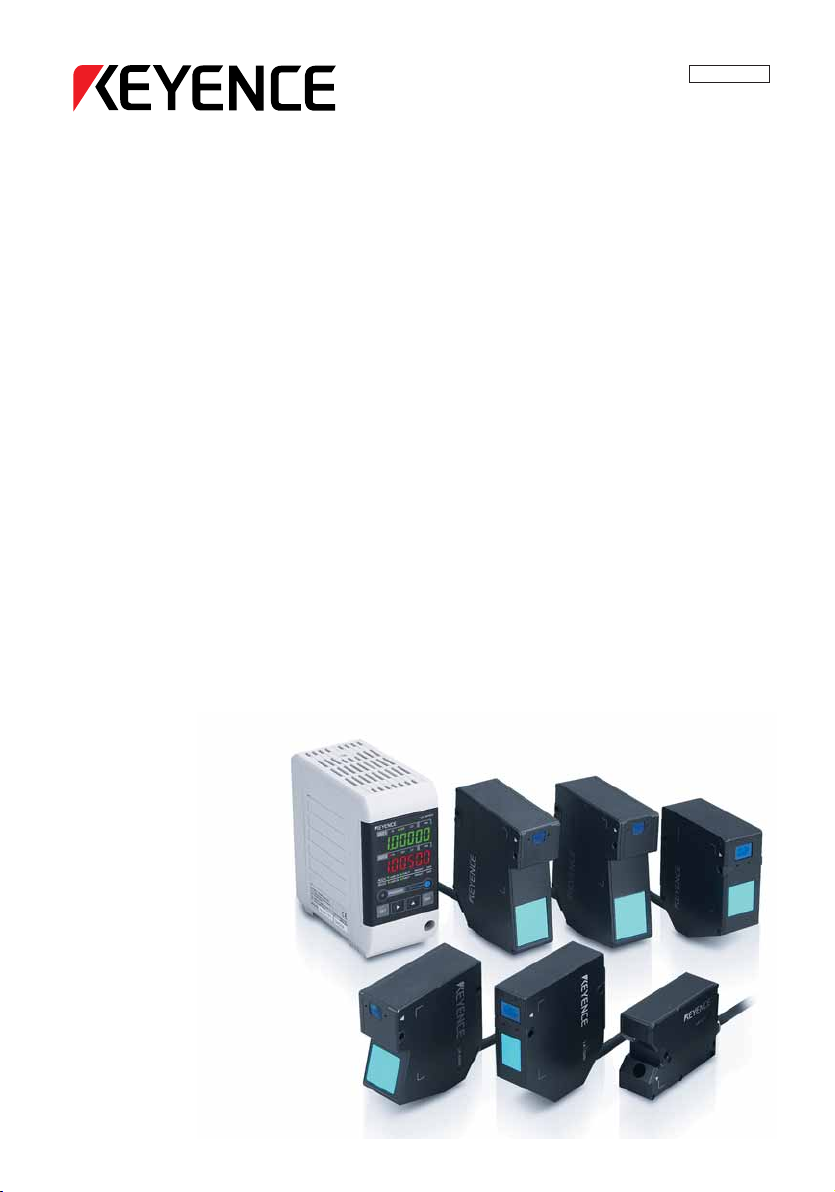
High-speed, High-accuracy
CCD Laser Displacement Sensor
LK-G Series
User’s Manual
Read this manual before using the system in order
to achieve maximum performance.
Keep this manual in a safe place for future
reference.
Page 2
Introduction
This Instruction Manual describes the basic operations and hardware functions of the LK-G
Series. Read this manual carefully to ensure the optimum performance and full function of the
LK-G Series before use.
Keep this manual in a safe place for future reference.
Be sure that the person who will finally operate this product receives this manual.
■
Symbols
These symbols alert you to matters concerning the prevention of human injury and product damage.
DANGER
Failure to follow the instructions may lead to death or serious injury.
WARNING
Failure to follow the instructions may lead to injury.
CAUTION
Failure to follow the instructions may lead to product damage or failure of the product.
Note
Provides additional information on proper operations that can be easily mistaken.
Reference
Provides advanced and useful information for operation.
Page 3

Safety Precautions
General Cautions
• At startup and during operation, be sure to monitor the functions and performance of
the LK-G Series.
• We recommend that you take substantial safety measures to avoid any damage in
the event of a problem occurring.
• Do not attempt to open or modify the LK-G Series or use it in any way other than as
described in the specifications. If the LK-G Series is modified or used other than as
described, the warranty will be voided.
• When the LK-G Series is used in combination with other devices, functions and
performance may be degraded, depending on the operating conditions and
surrounding environment.
• Do not use the LK-G Series for the purpose of protecting the human body.
• Do not allow the temperature to change sharply around the LK-G Series, including
the accessories. Otherwise, condensation may lead to malfunction.
WARNING
Follow the safety precautions below to ensure safe operation
• Apply the correct power voltage. Failure to do so may cause fire, electric shock, or
malfunction.
• Do not attempt to disassemble or modify the unit. Doing so may cause fire or electric
shock.
Handling abnormalities
Turn off the power immediately in the following cases. Using the unit in an abnormal
condition could cause fire, electric shock, or accident.
Contact the nearest KEYENCE office for repair.
• If liquid including water, chemicals or debris enters the unit.
• If the unit is dropped or the case is damaged.
• If abnormal smoke or odor is present.
LK-G-M-NO0-E
1
Page 4

CAUTION
Follow the safety precautions below to ensure safe operation
• Be sure to turn the power off when you plug/unplug the cable that leads to the unit
and its accessories. Not following this caution may result in damage.
• Do not turn off the power while setting items. The data being set or all the data may
be lost.
• Do not block the vent holes on the unit. Increase of internal temperature may cause
failure.
Installation environment
To use the LK-G Series correctly and safely, avoid installing it in the following locations;
doing so may lead to breakdown of the unit.
• Location that is humid, dusty or poorly ventilated
• Location with a high temperature such as a place exposed to direct sunlight
• Location where there are flammable or corrosive gases
• Location where the unit may be directly subjected to vibration or impact
• Location where water, oil or chemicals may splash onto the unit
• Location where static electricity is easily generated
Corrective action for noise
Do not install the LK-G Series near a power source or high-voltage cable, otherwise noise
may cause the LK-G Series to malfunction. Take corrective action for noise by using noise
filters, laying cables separately, and/or installing insulation on the controller and the
measuring unit. Use the single core shielded cable for the analog output cable.
Influence of ambient temperature
A change in the ambient temperature may cause the measurement to fluctuate. Be sure to
keep it stabilized. When the ambient temperature changes by 10 °C, it takes 60 minutes
for the distribution of internal temperature to equalize.
Operating ambient light intensity level
Do not use the LK-G Series near a lighting system that repeatedly and rapidly turns on
and off. If it is unavoidable to use the unit in such a place, install a light shielding board or
the like so that the light will not affect the measurement.
Warming up
Before using the LK-G Series, wait approximately 30 minutes after the power is turned on.
Otherwise, the measured value may gradually fluctuate because the circuit is not
immediately stable after the power is turned on.
2
LK-G-M-NO0-E
Page 5

Influence of dust or dirt
The measurement may fluctuate due to dirt, dust or fluid such as water or oil in the following cases:
• Adhesion on the protection glass: Blow the dirt off with clean air. If dirt persists, wipe
the glass surface gently using a soft cloth moistened with alcohol.
• Adhesion on the surface of the measuring target: Blow the dirt off with clean air or
wipe it off.
• Intrusion of floating or sprinkled dust or dirt into the light-axis range: In this case, take
corrective action with a protective cover or air purge.
Notes
Influence of vibration
When the measuring target is vibrating, the measured value may fluctuate. In this case,
increase the average number of times of measurement to achieve a more accurate value.
Measuring target
The measured value may fluctuate if the shapes or surfaces of the measuring targets vary. In
this case, use a known target and perform appropriate correction using the calibration function.
Handling
Do not wipe with a wet cloth, benzene, or thinner. Doing so may change the color or shape
of the unit. If the unit has much dirt on it, wipe it off with a cloth moistened with a mild
detergent, then wipe with a soft dry cloth.
Effect of atmospheric motions
Slow atmospheric motions may affect the measurement and result in fluctuation of the measured value.
In such a case, take the following countermeasures.
• Enclose the measurement portion with an appropriate enclosure.
•
Agitate the air between the measurement portion and the workpiece more strongly with a fan.
Precautions on CE Marking
The LK-G Series conforms to the EMC Directive subject to the conditions that the following
requirements are satisfied. In order to use this equipment in the EU countries, be sure that
the following requirements have already been satisfied beforehand.
The applicable standards are explained below.
LK-G-M-NO0-E
3
Page 6

EMI: EN61326, class A
EMS: EN61326
Length of the power cord that is connected to the Controller, and length of all input/output
cords must be limited to shorter than 30 m.
Precautions for Wiring
Part of the circuits between the inputs and output are internal common. Make sure that a
potential difference does not occur between internal common terminals due to a potential
difference between wires or external devices. Otherwise, it may cause malfunctions in the
unit or external devices.
Examples of Wiring
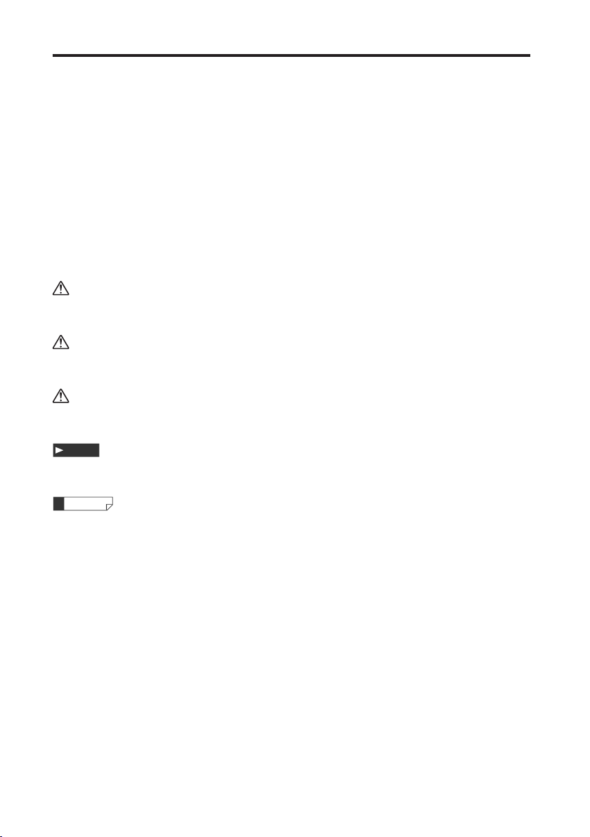
LK-G3001V/LK-G3001(NPN type)
24 VDC (-), COM OUT (output COM), and COM IN (input COM) are all common via a
choke coil. Also, COM OUT and COM IN of the expansion connector are common via a
choke coil.
LK-G3001(V) LK-G3001(V)
DC24V
COM OUT
COM IN
DC24V(+)
DC24V(-)
COM OUT
COM IN
DC24V(+)
DC24V
DC24V(-)
The power supply (24 VDC) shorts via the
COM terminals, causing malfunctions.
4
LK-G-M-NO0-E
Page 7
LK-G3001PV/LK-G3001P (PNP type)
24 VDC (-) and COM IN are common via a choke coil. Also, COM IN of the expansion
connector is common via a choke coil.
LK-G3001P(V)
COM OUT
LK-G3001P(V)
COM OUT
COM IN
DC24V(+)
DC24V(-)
DC24V
COM IN
DC24V(+)
DC24V
DC24V(-)
The power supply (24 VDC) shorts via the
COM terminals, causing malfunctions.
Common for all types
24 VDC (-), SG (GND) of USB, and SG (GND) of RS-232C are all common via a choke coil.
Make sure that a voltage potential difference does not occur with external devices such as
computers or PLC. If a voltage potential difference occurs, use the unit with insulation on
the LK-G power supply and the I/O terminals other than RS-232C and USB.
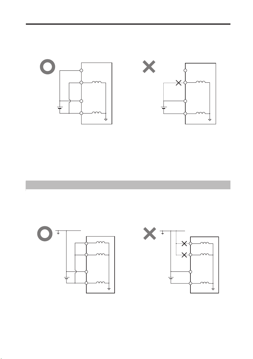
Precautions for a Positive Grounding Environment
When using a positive grounding environment, watch out for shorts through the COM
terminal.
LK-G3001V/LK-G3001 (NPN type)
GND
LK-G3001(V)
COM OUT
COM IN
GND
LK-G3001(V)
COM OUT
COM IN
DC24V
LK-G-M-NO0-E
DC24V(+)
DC24V(-)
DC24V(+)
DC24V
DC24V(-)
The power supply (24 VDC) shorts via the
COM terminals, causing malfunctions.
5
Page 8
LK-G3001PV/LK-G3001P (PNP type)
GND
LK-G3001P(V)
COM OUT
GND
LK-G3001P(V)
COM OUT
DC24V
COM IN
DC24V(+)
DC24V(
DC24V
-
)
COM IN
DC24V(+)
DC24V(
-
)
The power supply (24 VDC) shorts via the
COM terminals, causing malfunctions.
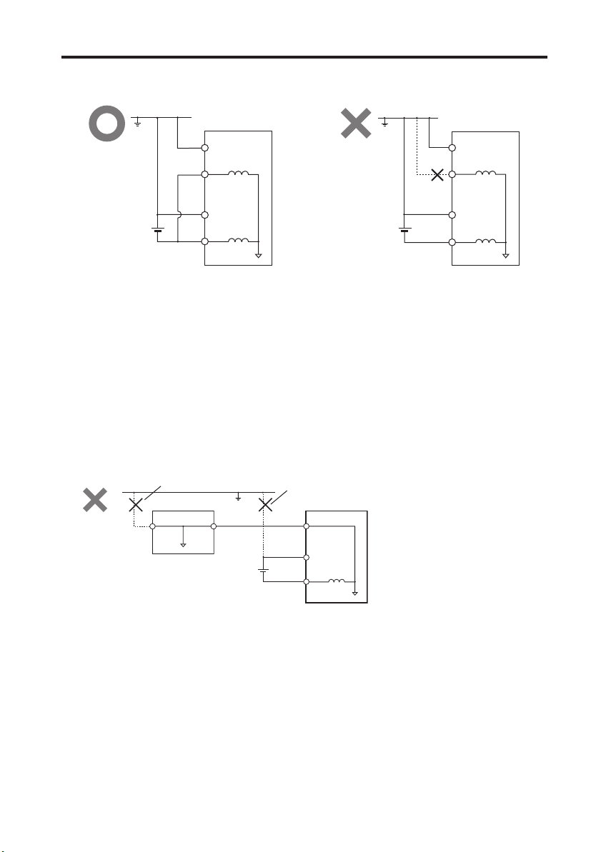
Precautions when connecting to computers or other external devices
When working in a positive grounding environment, when the LK-G is connected to a
computer through USB in order to use LK-Navigator or when establishing RS-232C
communication with a computer, take precautions to avoid shorts in between the SG
(GND) terminals for the computer and the LK-G.
24 VDC (-), SG (GND) of USB, and SG (GND) of RS-232C are all common via a choke coil.
Make sure that a voltage potential difference does not occur with external devices such as
computers or PLC. If a voltage potential difference occurs, use with insulation on the LK-G
power supply and the I/O terminals other than RS-232C and USB.
➀
Computer
GND
termin
al
RS-232C/
USB GND
GND
RS-232C/
USB cable
DC24V
➁
LK-G3001P(V)
RS-232/
USB GND
DC24V(
DC24V(+)
The power supply (24 VDC) shorts via
the SG (GND) terminals for LK-G and
the computer, causing malfunctions.
Insulate the computer (➀ in the figure)
and LK-G (➁ in the figure).
* The internal wiring in the computer,
PLC, or other device differs
depending on the device. For details,
refer to the instruction manual for each
-
)
device.
6
LK-G-M-NO0-E
Page 9
Safety Precautions on Laser Products
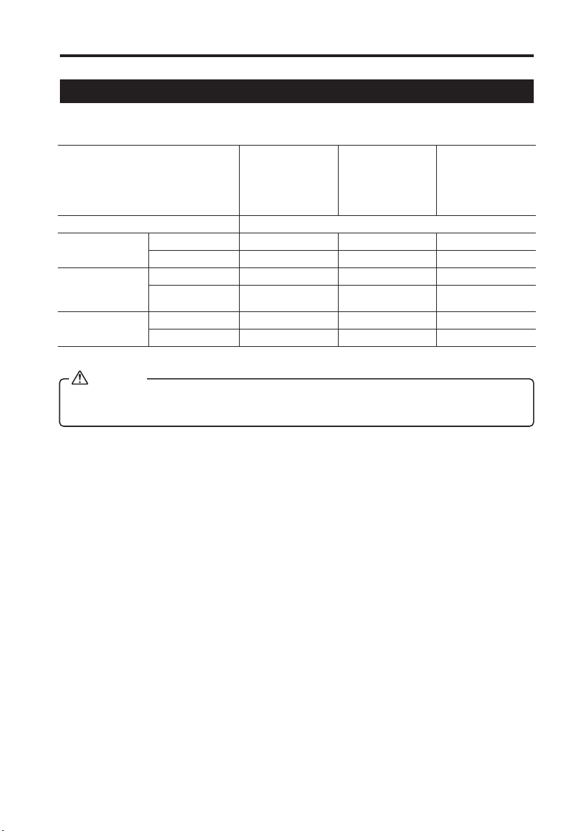
The models of the LK-G Series are classified in terms of laser class as follows:
Model LK-G35/LK-G30
Wavelength 650 nm
FDA (CDRH)
Part 1040.10
IEC60825-1:
1993 + A1:
1997 + A2: 2001
JIS C6802: 1997
Maximum output 4.8 mW 0.95 mW 0.3 mW
Class Class3a Class2 Class2
Maximum output 4.8 mW 0.95 mW 0.3 mW
Class
Maximum output 4.8 mW 0.95 mW 0.3 mW
Class Class 3A Class 2 Class 1
LK-G85/LK-G80
LK-G155/LK-G150
LK-G405/LK-G400
LK-G505/LK-G500
Class 3R Class 2
LK-G37/LK-G32
LK-G87/LK-G82
LK-G157/LK-G152
LK-G407/LK-G402
LK-G507/LK-G502
LK-G15/LK-G10
*
Class 1
*LK-G15/LK-G10 is a class 1 laser product according to IEC60825-1.
WARNING
Use of controls or adjustments or performance of procedures other than those
specified herein may result in hazardous radiation exposure.
Cautions on class
3333a/3R/3A laser products
Observe the following instructions. Otherwise, injury to the human body (eyes and skin) may
result.
• Do not direct the laser beam at other persons.
• Never look at the laser beam through optical instruments such as a microscope,
magnifier or telescope.
• Make the laser path as short as possible and be sure to terminate the laser path with
a diffusion reflector or diffusion absorber so that the laser beam does not diffuse. (It
is recommended to install the protection enclosure.)
• Install the laser product so that the laser beam be located well above or below eye
level.
• Install the laser product carefully so that the laser beam is not unitentionally directed
at mirror- like surfaces.
• It is recommended to wear protective eye goggles.
• Do not disassemble the LK-G Series.
• Do not look directly at the laser beam.
LK-G-M-NO0-E
7
Page 10

Cautions on Class
Observe the following instructions. Otherwise, injury to the human body (eyes and skin)
may result.
• Do not direct the laser beam at other persons.
• Do not disassemble the LK-G Series.
• Do not stare at the laser beam.
Cautions on Class 1 laser products
• Do not look directly at the laser beam for an extended period of time.
• Do not disassemble the LK-G Series.
2222/ 2 laser products
8
LK-G-M-NO0-E
Page 11
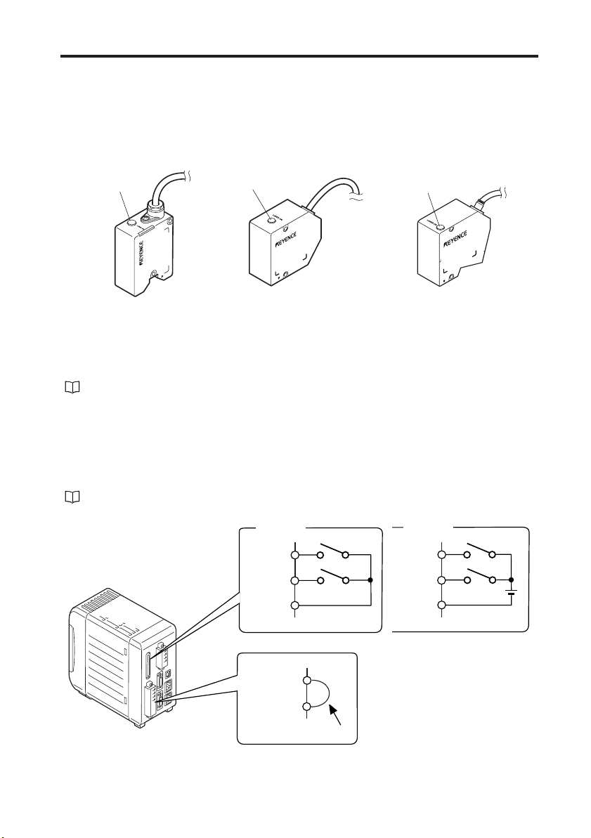
The LK-G Series is equipped with the following safety features based on IEC60825-1 and
L
CDRH Part 1040.10 (Safety of laser products).
■ Laser radiation emission warning indicator
Lights or flashes while the LK-G Series is in operation.
Laser emission
warning indicator
aser emission
warning indicator
Laser emission
warning indicator
■ Laser remote interlock connector
The laser beam stops radiation emission upon opening the circuit between the REMOTE
terminal and the COM IN terminal.
Refer to "12-pin I/O terminal block" (page 4-2) for connecting terminals.
■ Beam stop or attenuator
The laser beam stops radiation emission by the following operations :
• NPN type: Short-circuiting between the LASER OFF terminal and COM IN terminal.
• PNP type: Apply the voltage between the LASER OFF terminal and COM IN terminal.
Refer to "Expansion Connector" (page 4-5) for connecting terminals.
LK-G-M-NO0-E
NPN type
LASER
OFF A
LASER
OFF B
COM IN
REMOTE
COM IN
Short-circuiting wire
PNP type
LASER
OFF A
LASER
OFF B
COM IN
* The laser remote interlock
connector is delivered with the
wire for short-circuiting
installed.
9
Page 12

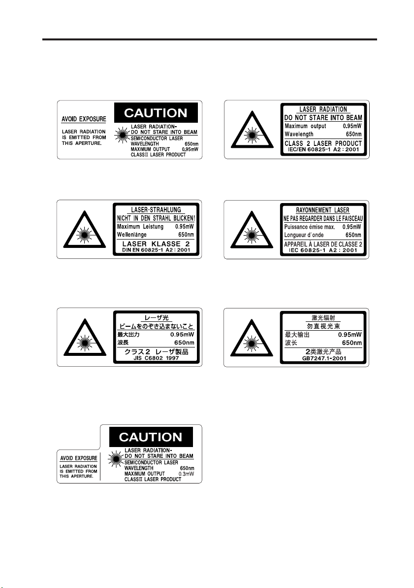
■ Warning labels
The contents of warning indications and locations for attaching warning labels are
described below.
The FDA (CDRH) warning labels are attached to the unit when shipped from the factory.
Labels other than the FDA (CDRH) label are supplied with the unit. Attach the other label(s)
to the locations as shown in the figure on page 9 according to the destinations of the
product.
Warning label are not supplied with LK-G15/LK-G10, because these models are IEC class
1 and JIS class 1 products.
■ Label contents
● LK-G35/LK-G30/LK-G85/LK-G80/LK-G155/LK-G150/LK-G405/LK-G400/LK-
G505/LK-G500
FDA (CDRH) IEC (English)
IEC (German) IEC (French)
JIS (Japanese) GB (Simplified Chinese)
10
LK-G-M-NO0-E
Page 13
● LK-G37/LK-G32/LK-G87/LK-G82/LK-G157/LK-G152/LK-G407/LK-G402/LK-
G507/LK-G502
FDA (CDRH) IEC (English)
IEC (German) IEC (French)
JIS (Japanese) GB (Simplified Chinese)
● LK-G15/LK-G10
FDA (CDRH)
LK-G-M-NO0-E
11
Page 14

■ Label attachment locations
● LK-G35/LK-G30/LK-G37/LK-G32
LK-G85/LK-G80/LK-G87/LK-G82
● LK-G155/LK-G150/LK-G157/LK-G152
LK-G405/LK-G400/LK-G407/LK-G402
LK-G505/LK-G500/LK-G507/LK-G502
● LK-G15/LK-G10
12
AVOID EXPOSURE
LASER RADIATION
IS EMITTED FROM
THIS APERTURE.
CAUTION
LASER RADIATION
DO NOT STARE INTO BEAM
SEMICONDUCTOR LASER
WAVELENGTH
MAXIMUM OUTPUT
CLASS LASER PRODUCT
-
650nm
0.3mW
CAUTION
LASER RADIATION
DO NOT STARE INTO BEAM
SEMICONDUCTOR LASER
WAVELENGTH
MAXIMUM OUTPUT
CLASS LASER PRODUCT
-
AVOID EXPOSURE
LASER RADIATION
650nm
IS EMITTED FROM
0.3mW
THIS APERTURE.
LK-G-M-NO0-E
Page 15
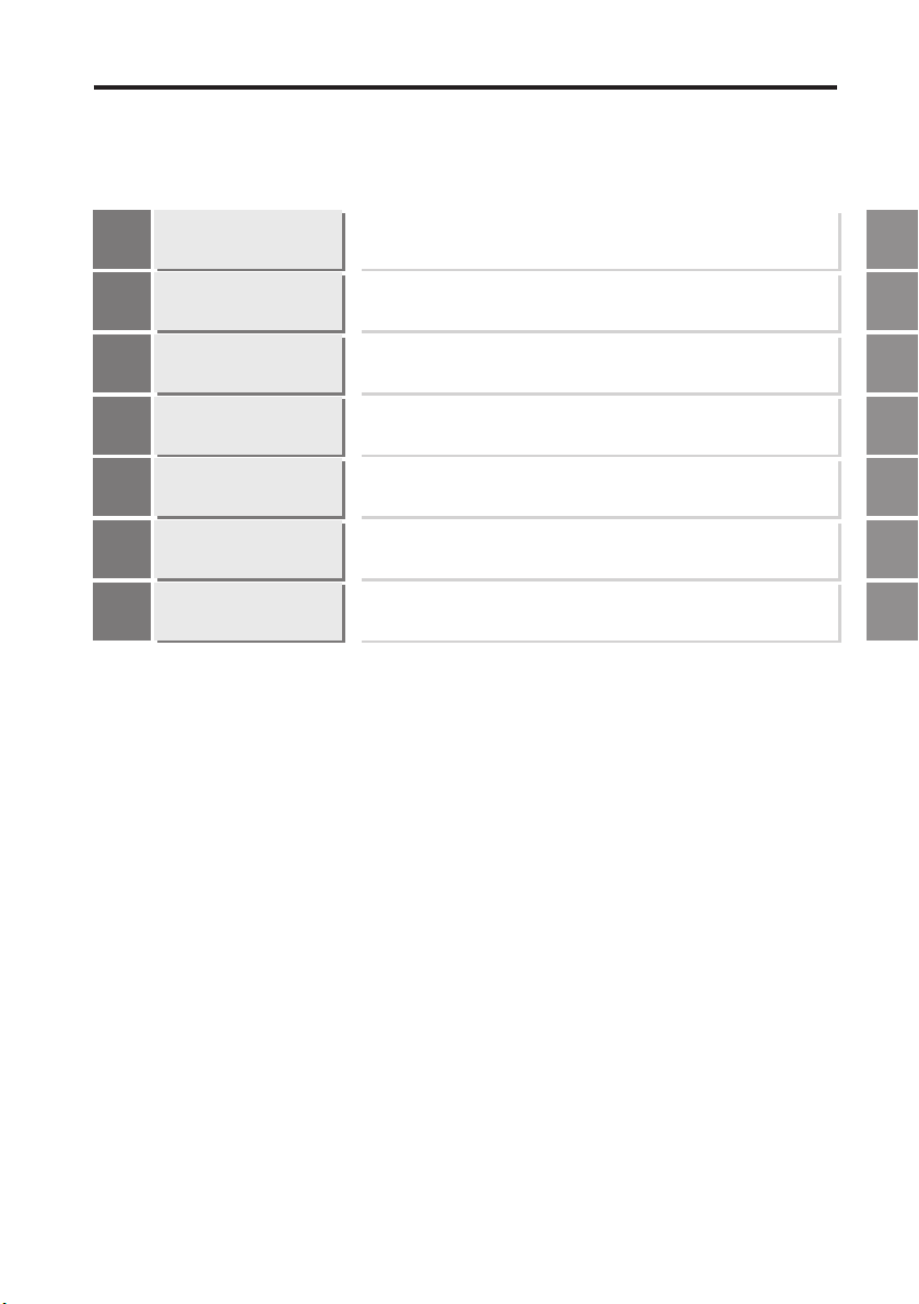
Organization of this Manual
Chapter
Before Use
1
Chapter
Operations and Functions
during Measurement
2
Chapter
Function Settings
3
Chapter
Input/Output
Terminals
4
Chapter
RS-232C
5
Chapter
Specifications
6
Describes cautions and preparations before use.
Describes the operations that can be performed during displacement measurement and their functions.
Describes the functions and setting procedures of the
Head settings, Output settings, Common settings, and
Environment settings.
Describes the specifications of the input/output
terminals and timing chart.
Describes the functions of the RS-232C interface
and the setting procedures.
Describes the specifications of the controller and the
head, outside dimensions, and characteristics.
1
2
3
4
5
6
Appendices
Appendices
Describes the troubleshooting methods, contents of
error messages and optional products.
LK-G-M-NO0-E
13
Page 16

14
LK-G-M-NO0-E
Page 17

Table of Contents
Safety Precautions .................................. 1
General Cautions............................... 1
WARNING ..................................... 1
CAUTION ...................................... 2
Notes.................................................. 3
Precautions on CE Marking ............... 3
Precautions for Wiring................... 4
Safety Precautions on Laser Products
Organization of this Manual .................. 13
Table of Contents .................................. 14
Chapter 1 Before Use
System Configuration ........................... 1-2
Checking the Package Contents ......... 1-3
LK-G3001V/LK-G3001PV
(Single Unit Type Controller)........... 1-3
LK-G3001/LK-G3001P
(Separate Type Controller) ............. 1-3
LK-GD500
(Separate Type Controller) ............. 1-4
Head (LK-G15/LK-G10).................. 1-4
Head (Model other than LK-G15/
LK-G10) .......................................... 1-4
LK-GC2/GC5/GC10/GC20/GC30 ... 1-5
Identifying Part Names and Functions
Controller ........................................ 1-6
Head ............................................... 1-8
Installing and Connecting the Heads and
Optional Parts ...................................... 1-9
Installing the Head.......................... 1-9
Attaching the ND Filter (Option) ... 1-15
Installations Depending on the
Measurement Target..................... 1-16
Installing the Controller................. 1-17
Connection.................................... 1-22
Outline of Measurement and Settings 1-24
Switching Modes .......................... 1-24
..... 7
.... 1-6
Setting Mode................................. 1-25
Returning the LK-Series to the Factory
Default Settings .................................. 1-26
Chapter 2
Operations and Functions
during Measurement
Switching the Measurement
Value Displays .....................................2-2
Setting the Tolerance
Comparator Value ................................ 2-3
The Function of the
Tolerance Settings .......................... 2-3
Hysteresis .......................................2-5
Setting the Display Value Instantaneously
to Zero (Auto-Zero) ..............................2-6
Program Function ................................ 2-8
Switching Program Nos. ......................2-9
Performing Statistical Computation
with the Measurement Value .............. 2-10
Chapter 3 Function Settings
Measurement, Data Flow and
Functions ............................................. 3-2
Setting the Head .................................. 3-3
List of Functions and Function Nos
List of Default Values and Setting
Ranges............................................ 3-3
List of the Head Setting Screens ....3-4
Setting ABLE................................... 3-5
Setting the Measurement Mode
According to the Measuring
Target.............................................. 3-7
Specifying the Process When
Measurement is Not Possible
(Alarm Process) ..............................3-8
Automatically Teaching the Adjustment Range
of ABLE According to the Target
Setting the Mounting Mode........... 3-12
Setting the Conditions of the Measurement
Value Output ...................................... 3-13
.... 3-3
.......... 3-10
14
LK-G-M-NO0-E
Page 18

List of Functions and Function Nos
List of Default Values and Setting
Ranges ..........................................3-15
List of the OUT Setting Screens ....3-16
Calculating Between the Heads....3-18
Setting the Scaling for Measurement
(Calibration)...................................3-20
Stabilizing the Measurement by
Filtering..........................................3-22
Using the Hold Function
(Measurement Mode)....................3-25
Setting the Trigger Condition ........3-31
Measuring with Offset....................3-32
Setting the Unit and the Minimum
Display Unit ...................................3-33
Scaling the Analog Output ............3-34
Outputting the Analog Output Without
Holding..........................................3-36
Setting the Common Function ............3-37
List of Functions and Function Nos
List of Default Values and Setting
Ranges ..........................................3-37
List of the Common Function Setting
Screens .........................................3-38
Setting the Sampling Rate of
Measurement Value.......................3-39
Setting the Mutual Interference
Prevention Function.......................3-40
Setting the External Timing Input ..3-41
Setting the Output Form of the
Tolerance Comparator ..................3-42
Setting the Strobe Output Time .....3-43
Accumulating the Measurement Value in the
Memory (Data Storage Function)
Setting the Operations of the Equipment
(Environment Settings) .......................3-46
List of Functions and Function Nos
List of Default Values and Setting
Ranges ..........................................3-47
List of the Environment Setting Screens
.......................................................3-48
..3-13
.....3-37
.......3-44
.....3-46
Setting the Communication
Specifications of the RS-232C...... 3-49
Setting the Program Switching Method
...................................................... 3-50
Copying/Initializing the Program .. 3-51
Preventing Erroneous Operation on the
Panel (Panel Lock) ....................... 3-53
Reducing the Power Consumption
(Eco Mode)................................... 3-54
Chapter 4 Input/Output Terminals
Identifying Names and Functions of the
Input/Output Terminals ........................ 4-2
Functions of the Input/
Output Terminals ............................ 4-2
Functions of the Input and Output
Signals............................................ 4-7
Timing Chart ...................................... 4-13
Chapter 5 RS-232C
Specifications ...................................... 5-2
Pin Layout....................................... 5-2
Communication Specifications....... 5-2
Communication Performance and
Communication Mode in the
Measurement State ........................ 5-3
Overview of the Settings According to
External Devices............................. 5-3
Outputting Measurement Values and
Changing Settings through Commands
Connecting the PC or PLC Link Unit5-4
Mode Change Command............... 5-7
Measurement Control Command
Format ............................................ 5-8
Change Parameter Command ..... 5-13
Check Parameter Command Format
Timing Chart ................................. 5-21
Outputting Measurement Values in External
Synchronization ................................. 5-22
Environment Settings Parameters
.... 5-4
.. 5-20
... 5-22
LK-G-M-NO0-E
15
Page 19

Output........................................... 5-22
Timing Chart ................................. 5-23
Output Format............................... 5-24
ASCII Code Table (Reference) ..... 5-24
Chapter 6
Specifications of the LK-G
Series
Specifications ...................................... 6-2
Specifications of the Controller....... 6-2
Specifications of the Head.............. 6-4
Specifications of the Head-to-Controller
Cable ............................................ 6-15
Status Table.................................. 6-15
Response Delay Time................... 6-17
Outside Dimensions...................... 6-17
Characteristics ................................... 6-25
Spot Dimension............................. 6-25
Mutual Interference....................... 6-27
Appendices
Troubleshooting....................................A-2
Error Messages.....................................A-5
List of Optional Products ......................A-6
Index.....................................................A-8
16
LK-G-M-NO0-E
Page 20

17
LK-G-M-NO0-E
Page 21

Before Use1
Before Use1
This chapter describes the configuration of the LK-G Series, cautions
and required preparation before use. Be sure to read this section thoroughly before using the LK-G Series.
System Configuration ............................................................1-2
Checking the Package Contents ...........................................1-3
Identifying Part Names and Functions ..................................1-6
Installing and Connecting the Heads and Optional Parts......1-9
Outline of Measurement and Settings .................................1-24
Returning the LK-Series to the Factory Default Settings.....1-26
1
LK-G-M-NO1-E
1-1
Page 22
1 Before Use
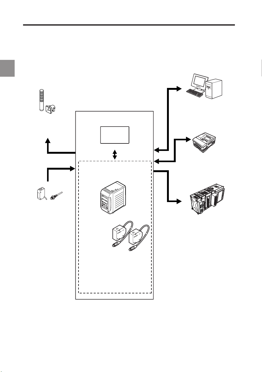
System Configuration
The LK-G Series can be used for various purposes in combination with commercially available
devices.
1
Indicator light/Buzzer
Issues an alarm depending on
the comparator result output.
Photoelectric/Proximity sensor
Transmits a signal to the
TIMING input when the target
is detected.
LK-G Series
LK Navigator
Setup support software (LK-H1W) *2
USB/RS-232C
*1
Controller
LK-G3001V/LK-G3001PV
LK-G3001/LK-G3001P
Head (two heads max.)
LK-G15/LK-G10
LK-G35/LK-G30
LK-G85/LK-G80
LK-G155/LK-G150
LK-G405/LK-G400
LK-G505/LK-G500
PC
Enables control and acquisition
of the measurement value from
the RS-232C or the parallel I/O
board.
Programmable controller
Enables timing control of the
measurement and the switching
of program No. as well as the
control output and the
measurement value acquisition.
Recorder
Records the measurement result.
*1: The controller (LK-G3001V/LK-G3001PV) can be separated into the display panel and the controller main
unit. You can also purchase them separately.
*2: For the details of the setup support software (LK-H1W) "LK-Navigator", refer to "LK-Navigator User’s
Manual" (The PDF file stored in the CD-ROM).
1-2
LK-G-M-NO1-E
Page 23
1 Before Use
Checking the Package Contents
The LK-G Series consists of the following models. Check if the parts and equipment listed
below are included in the package of the model you purchased before using the unit.
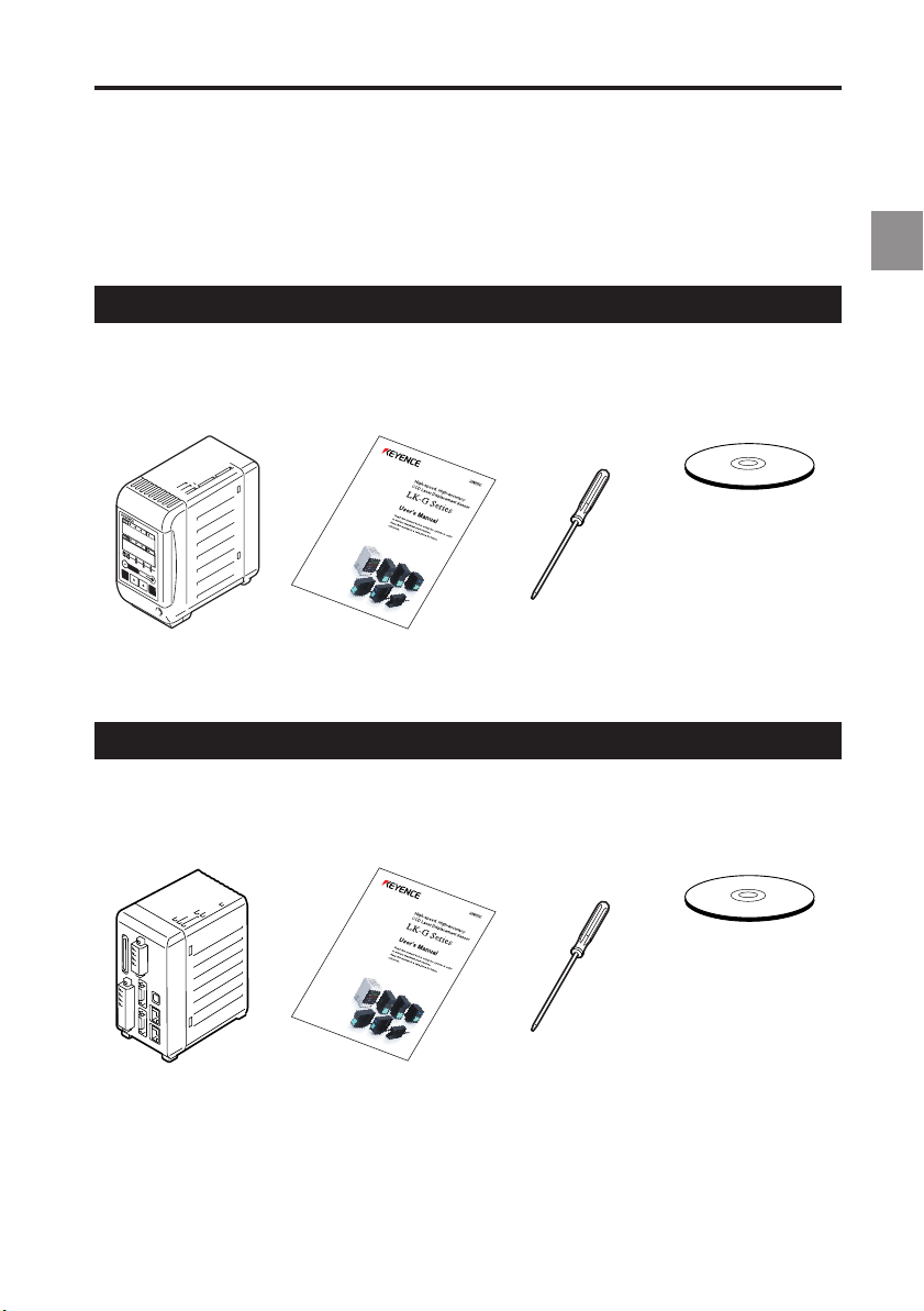
LK-G3001V/LK-G3001PV (Single Unit Type Controller)
1
Controller User’s Manual Screwdriver
LK-G3001V/ (this manual): 1 : 1
LK-G3001PV: 1
LK-G3001/LK-G3001P (Separate Type Controller)
Controller User’s Manual Screwdriver
LK-G3001/ (this manual): 1
LK-G3001P/: 1
Packed separately
LK-H1W (
• Setup support
• Setup support
USB cable (3m)
Packed separately
LK-H1W (
• Setup support
• Setup support
USB cable (3m)
CD-ROM)
software
"LK-Navigator"
software
User’s Manual
(PDF file)
CD-ROM)
software
"LK-Navigator"
software
User’s Manual
(PDF file)
LK-G-M-NO1-E
1-3
Page 24
1
1 Before Use
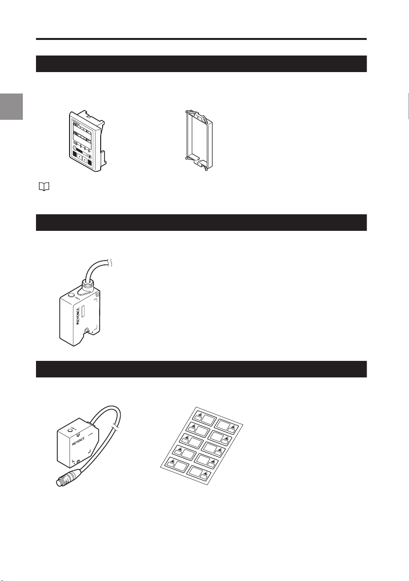
LK-GD500 (Separate Type Controller)
Display panel Panel attachment ring
LK-GD500: 1 : 1
The communication cable between the controller and the separate type display panel is
sold separately. Refer to page A-6 for details.
Head (LK-G15/LK-G10)
Head: 1
LK-G10
Head (Model other than LK-G15/LK-G10)
Head: 1 Laser sticker sheet: 1
1-4
LK-G-M-NO1-E
Page 25

1 Before Use
LK-GC2/GC5/GC10/GC20/GC30
Head-to-controller cable: 1
LK-GC2 : 2-m cable
LK-GC5 : 5-m cable
LK-GC10 : 10-m cable
LK-GC20 : 20-m cable
LK-GC30 : 30-m cable
* We have thoroughly inspected the package contents before shipment. However, in the
event of defective or broken items, contact your nearest KEYENCE office (address
listed in the end of this manual).
For the optional products,refer to "List of Optional Products"(page A-6).
1
LK-G-M-NO1-E
1-5
Page 26
1 Before Use
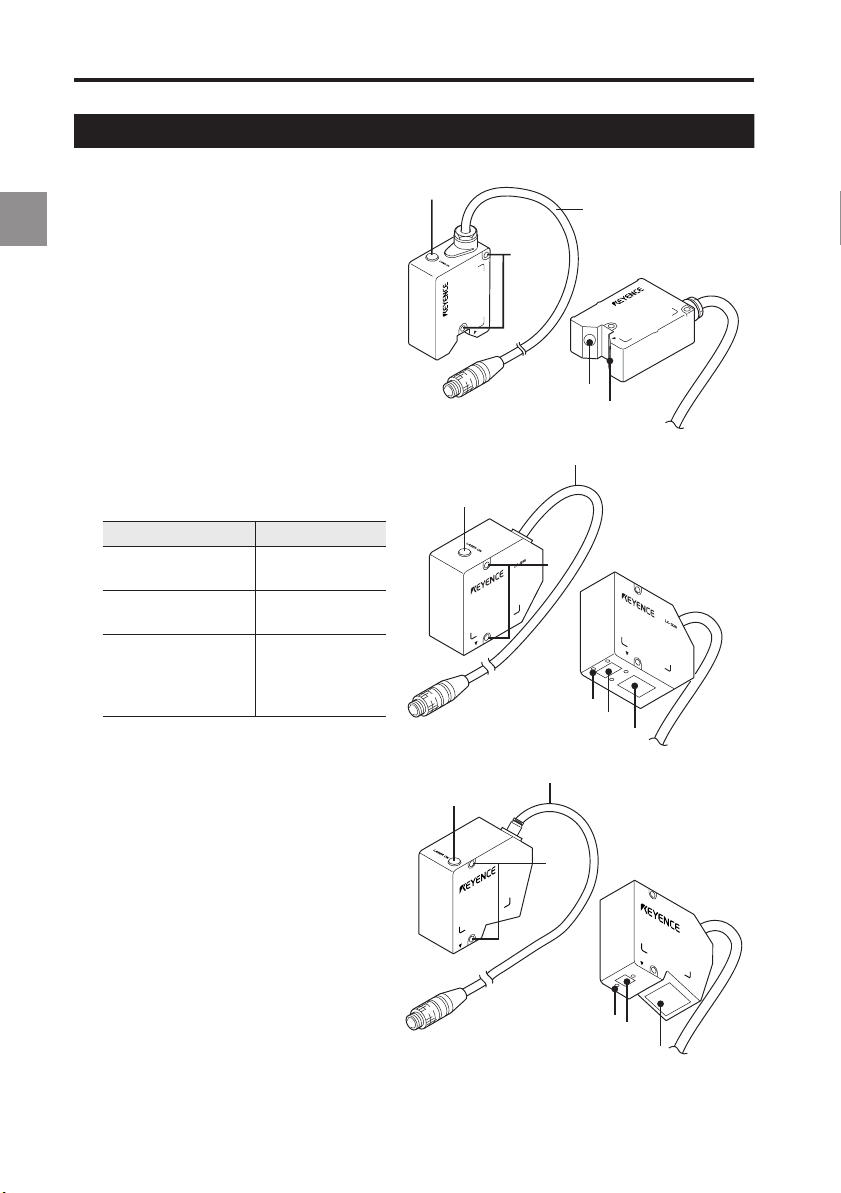
Identifying Part Names and Functions
This section describes the name and function of each part.
1
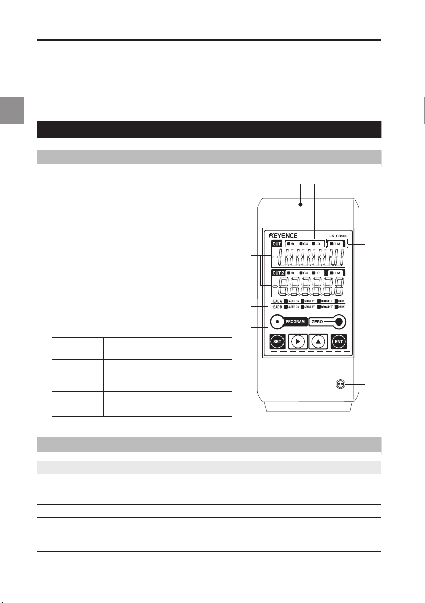
Controller
Display panel
1 Display panel fixing case
14
2 Display panel fixing screw
3 Measurement value indicators
Display the measurement value, tolerance
comparator value, and various statistical results.
The setting items are displayed during setting.
Green: Within the tolerance Red: Outside the tolerance
4 Comparator output indicator
3
5
Lights during the comparator output (HI, GO, or LO).
5 Timing input indicator
Lights when the timing signal is being input.
6 Head status display indicator
Displays the laser emission status and the
measurement status.
LASER ON Laser emission LED. Lights while
STABILITY
BRIGHT
DARK
the LK-G Series is in operation.
Lights in green or orange within the
measurement range. Lights in red outside
the measurement range, alarm, or laser-off.
Lights at the exceeding light intensity alarm.
Lights at the light intensity shortage alarm.
6
7
2
7 Operation keys
Displays and descriptions of the measurement value indication
Display Description
Numerical value (±999999)
FFFFFF (HI output: ON. Monitor output: + 10.8 V) Displayed when the value exceeds the display range.
–FFFFFF (LO output: ON. Monitor output: –10.8 V)
- - - - - -
(HI, GO and LO outputs: OFF. Monitor output: –10.8 V)
Displays the measurement result in numerical value.
The display unit, decimal point position, and minimum
display unit vary depending on the settings.
Displayed when the value drops below the display range.
Displayed during the comparator standby state.
1-6
LK-G-M-NO1-E
Page 27

Operation keys
Key Function
1 Before Use
• During measurement it calls the Program switch mode.
• During measurement it calls the Tolerance setting mode.
• When pressed for one second, it calls the Operation setting mode.
• During setting it cancels the setting content and returns to the previous setting.
• During measurement it calls the Statistics display mode.
• During setting it determines the content.
• During measurement it sets the measurement value to zero.
• When pressed for three seconds it cancels auto-zero.
When pressed for three seconds while inputting the value, it initializes the selected item.
•
•
During setting it switches the display to the next setting item.
• While inputting the value it shifts one digit right.
• When pressed for one second or more it shifts in higher speed.
During measurement it changes the display for OUT1, OUT2 or both at the same time.
•
• During setting it switches the setting content.
• While inputting the value it switches symbols or sets numerical values.
• When pressed for one second or more it shifts in higher speed.
Terminal panel
1 RS-232C connector
Establishes communication with a PC or a PLC.
Refer to "Pin Layout" (page 5-2).
2 USB connector
Used when connecting the PC via USB.
Refer to "LK-Navigator User’s Manual" for details.
3 6-pin terminal block
Refer to "6-pin I/O terminal block" (page 4-4).
4 Expansion connector
Refer to "Expansion connector" (page 4-5).
5 Head connectors
6 Laser emission LED.
Lights while the LK-G series operates.
7 Display panel connector
Connects the communication cable between the display
panel and the controller.
8 12-pin terminal block
Refer to "12-pin I/O terminal block" (page 4-2).
1
3
6
4
8
5
2
1
7
LK-G-M-NO1-E
1-7
Page 28
1 Before Use
Head
1 Sensor (emitter)
Emits the laser beam for measurement. It
1
is protected with a glass cover.
2 Sensor (receiver)
Receives the laser beam for measurement. It is protected with a glass window.
3 Attachment holes for the ND filter
Used for attaching the ND filter (LK-F1/
LK-F2).
4 Installation holes
5 Connecting cable
Connected to the head-to-controller
cable.
6 Laser radiation emmission LED
Lights or flashes while the LK-G Series is
in operation.
Status LED
Center of the
measurement range
Within the
measurement range
Outside the
measurement range
Alarm
Laser off
Lights in green
Lights in orange
Flashes in
orange
6
4
6
5
2
1
5
4
3
1
2
1-8
5
6
4
3
1
2
LK-G-M-NO1-E
Page 29
1 Before Use
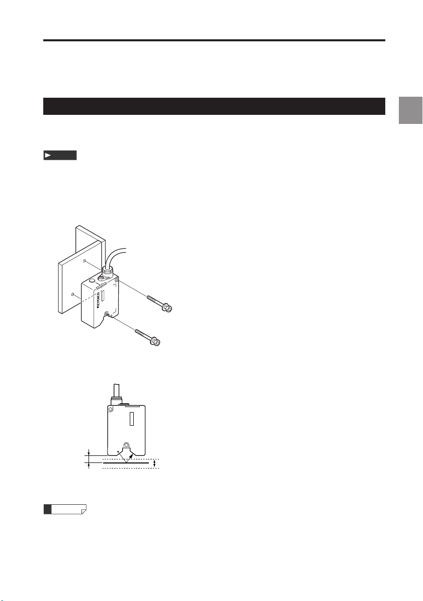
Installing and Connecting the Heads and Optional Parts
Installing the Head
Adjust the distance between the head and the measuring target, and fix the head with the
screws at the two installation holes.
Note
Insulated mounting is recommended when using the head under the positive grounding
environment.
■ LK-G15/LK-G10
• Installation procedure
LK-G10
M4r35 mm or more
The measurement range is shown in the figure below.
1
LK-G10
Reference
distance
10 mm
Reference
distance
0 mm
+1mm
Measurement range
–1 mm
(–0.37mm)
* The value inside the parentheses ( ) is when the sampling rate is 20 µs.
Reference
The laser emission LED at both diffuse reflection and specular reflection lights in green
within ±0.05 mm of the reference position, and lights in orange in the other positions in the
measurement range.
LK-G-M-NO1-E
1-9
Page 30

1 Before Use
■ LK-G35/LK-G30/LK-G37/LK-G32
• Installation procedure
1
M4r35 mm or more
The measurement range is shown in the figure below.
• Diffuse reflection setup • Specular reflection setup
Reference
distance
30 mm
Reference
distance
0 mm
+5mm
Measurement range
–5 mm
(–1.8 mm)
Reference
distance
23.5 mm
Reference
distance
0 mm
40°
+4.5mm
Measurement range
–4.5mm
(–1.6 mm)
* The value inside the parentheses ( ) is when the sampling rate is 20 µs.
Reference
• The laser emission LED at both diffuse reflection and specular reflection lights in
green within ±0.25 mm of the reference position, and lights in orange in the other
positions in the measurement range.
1-10
LK-G-M-NO1-E
Page 31

■ LK-G85/LK-G80/LK-G87/LK-G82
• Installation procedure
LK-G85
M4r45 mm or more
The measurement range is shown in the figure below.
• Diffuse reflection setup • Specular reflection setup
1 Before Use
1
Reference
distance
80 mm
Reference
distance
0 mm
LK-G85
+15mm
Measurement range
–15 mm
(+9mm)
Reference
distance
75.2 mm
Reference
distance
0 mm
17°
LK-G85
+14mm
Measurement range
–14mm
(+8.7mm)
* The value inside the parentheses ( ) is when the sampling rate is 20 µs. Note that the
measurement range narrows, disabling measurements at the reference position.
Reference
• The laser emission LED at both diffuse reflection and specular reflection lights in
green within ±0.75 mm of the reference position, and lights in orange in the other
positions in the measurement range.
• Select the mounting mode ( page 3-12) according to the installation conditions.
Note
The measurement range when measuring a mirror surface or a glass surface at the time of
specular reflection setup is between +14 (NEAR side) to –8.2 mm (FAR side). When the
sampling rate is 20 µs, the value becomes +14 (NEAR side) to +8.7 mm (NEAR side).
LK-G-M-NO1-E
1-11
Page 32

1 Before Use
■ LK-G155/LK-G150/LK-G157/LK-G152
• Installation procedure
1
LK-G150
M4r40 mm or more
The measurement range is shown in the figure below.
• Diffuse reflection setup • Specular reflection setup
Reference
distance
150 mm
Reference
distance
0 mm
LK-G150
+40mm
Measurement range
–40 mm
(+22mm)
Reference
distance
147.5 mm
Reference
distance
0 mm
17°
LK-G150
+39mm
Measurement range
–39mm
(+22mm)
* The value inside the parentheses ( ) is when the sampling rate is 20 µs. Note that the
measurement range narrows, disabling measurements at the reference position.
Reference
• The laser emission LED at both diffuse reflection and specular reflection lights in
green within ±2 mm of the reference position, and lights in orange in the other
positions in the measurement range.
• Select the mounting mode ( page 3-12) according to the installation conditions.
Note
The measurement range when measuring a mirror surface or a glass surface at the time of
specular reflection setup is between +39 (NEAR side) to –24 mm (FAR side). When the
sampling rate is 20 µs, the value becomes +39 (NEAR side) to +22 mm (NEAR side).
1-12
LK-G-M-NO1-E
Page 33

■ LK-G405/LK-G400/LK-G407/LK-G402
• Installation procedure
LK-G405
M4r45 mm or more
The measurement range is shown in the figure below.
• Diffuse reflection setup • Specular reflection setup
1 Before Use
1
Reference
distance
400 mm
Reference
distance
0 mm
LK-G405
+100mm
Measurement range
–100mm
(+70mm)
Reference
distance
398 mm
Reference
distance
0 mm
17°
LK-G405
+99mm
Measurement range
–99mm
(+70mm)
* The value inside the parentheses ( ) is when the sampling rate is 20 µs. Note that the
measurement range narrows, disabling measurements at the reference position.
Reference
• The laser emission LED at both diffuse reflection and specular reflection lights in
green within ±5 mm of the reference position, and lights in orange in the other
positions in the measurement range.
• Select the mounting mode ( page 3-12) according to the installation conditions.
Note
When using LK-G405/G400/G407/G402, select function No. G-1 or G-0 (page 33).
The measurement range when measuring a mirror surface or a glass surface at the time of
specular reflection setup is between +72 (NEAR side) to –50 mm (FAR side). When the
sampling rate is 20 µs, the value becomes +72 (NEAR side) to +70 mm (NEAR side).
LK-G-M-NO1-E
1-13
Page 34

1 Before Use
■ LK-G505/LK-G500/LK-G507/LK-G502
• Installation procedure
1
LK-G505
M4r45 mm or more
The measurement range is shown in the figure below.
• Diffuse reflection setup • Specular reflection setup
Reference
distance
500 mm
Reference
distance
0 mm
LK-G505
+250mm
Measurement range
–500mm
(+125mm)
(+230mm)
*1
*2
Reference
distance
497.5 mm
Reference
distance
0 mm
17°
LK-G505
+249mm
Measurement range
–498mm
(+125mm)
(+230mm)
*1
*2
*1 The value inside the parentheses ( ) is when the sampling rate is 50 µs.
*2 The value inside the parentheses ( ) is when the sampling rate is 20 µs.
Note that the measurement range narrows in either case, disabling measurements at the
reference position.
Reference
• The laser emission LED at both diffuse reflection and specular reflection lights in
green within ±12.5 mm of the reference position, and lights in orange in the other
positions in the measurement range.
• Select the mounting mode ( page 3-12) according to the installation conditions.
Note
When using LK-G505/G500/G507/G502, select function No. G-1 or G-0 (page 33).
The measurement range when measuring a mirror surface or a glass surface at the time of
specular reflection setup is between +173 (NEAR side) to +49.5 mm (NEAR side). When the
sampling rate is 50 µs, the value becomes +173 (NEAR side) to +125 mm (NEAR side). Note
that the measurement is disabled when the sampling rate is 20 µs.
1-14
LK-G-M-NO1-E
Page 35

1 Before Use
Attaching the ND Filter (Option)
If the head is installed for specular reflection and and the measurement target is a shiny
mirror or glass surface, the measurement accuracy may deteriorate. In such a case,
attach the ND filter (LK-F1) to ensure accurate measurement.
• LK-G35/LK-G30/LK-G37/LK-G32
LK-G85/LK-G80/LK-G87/LK-G82
• LK-G155/LK-G150/LK-G157/LK-G152
LK-G405/LK-G400/LK-G407/LK-G402
LK-G505/LK-G500/LK-G507/LK-G502
1
ND filter
LK-F1
Mounting screw x 4
(M1.6 x 3 countersink-head screw)
ND filter
LK-F2
Mounting screw x 2
(M1.6 x 3 countersink-head screw)
LK-G-M-NO1-E
1-15
Page 36

1 Before Use
Installations Depending on the Measurement Target
Measuring distance
Use the head as close to the reference distance as possible. Doing so stabilizes
the detection.
1
Target shape
The installation of the head in the orientations indicated by the circle in the figures below is
recommended.
Near the wall surface
Height-difference measurement
LK-G35
(a) (b)
LK-G35
Displacement in a hole
LK-G35 LK-G35
1-16
LK-G-M-NO1-E
Page 37

Installing the Controller
Install the controller to the DIN rail, or fix it with screws.
1 Before Use
Caution on the orientation of the LK-G Series
Install the controller in the orientations shown in the following figures with a circle. Do not install
it upside down.
Be sure to leave 30 mm of clearance or more above the
controller, and 10 mm or more on each side.
In addition, for ensuring the safe connection of the cord,
30mm
leave 65 mm space or more in front of the terminal panel of
the controller.
mm
10
10
mm
When installing the controllers side-by-side, make sure
there is a clearance of 10 mm or more between the
controllers and 30 mm or more of clearance above them.
30mm 30mm
1
10
mm
10
mm
CAUTION
• Do not cover the ventilation holes on the top and bottom of the controller. The heat
may stay inside causing a malfunction.
• When the temperature in the controller panel rises to over 50 °C, decrease the
ambient temperature below 50 °C by introducing forced cooling air or by securing
more room around the system.
LK-G-M-NO1-E
10
mm
1-17
Page 38

1 Before Use
Installing the LK-G3001V/LK-G3001PVLK-G3001PV (single unit type controller)
Install it on its bottom.
1
Installing the LK-G3001/LK-G3001P and LK-GD500 (separate type controller)
M4 screw x 4 (screw depth 6 mm)
Display panel (LK-GD500)
Display panel
Panel attachment
ring
Control panel
Insert the display panel
from the front, and fix it with
the panel attachment ring.
When removing the display
panel, while pushing up the two
cutouts of the attachment ring
with a flat-head screwdriver
and push out the display panel.
Controller (LK-G3001/LK-G3001P)
• Installing on a DIN rail • Installing on its bottom
Two cutouts
M4 screw x 4
(screw depth 6 mm)
1-18
LK-G-M-NO1-E
Page 39

Separating the single unit type controller
Disconnect the display panel cable from the display panel connector on the
1
controller’s terminal panel.
Remove the display panel cable from the guide on the bottom of the controller.
Loosen the display panel fixing screw.
2
Reference
The display panel fixing screw does not drop from the display panel fixing case.
Remove the display panel fixing case from the controller.
3
(1)
Remove the
display panel
fixing case in
the directions
of the arrows.
(2)
1 Before Use
1
While pushing (1) and (2) outward in this order, push the display panel to
4
remove the panel attachment ring.
Panel attachment ring
(1)
(2)
Remove the display panel from the display panel fixing case.
5
LK-G-M-NO1-E
Panel attachment
ring
(3)
1-19
Page 40

1
1 Before Use
Combining the separate type controller
Install the display panel by aligning it with the two protrusions on the display
1
panel fixing case.
Display Panel
Two protrusions
Display panel fixing case (optional)
Fix the display panel with the panel attachment ring, and connect the 30-cm display
2
cable (optional).
Panel attachment ring
Two claws
Fix the cable by fitting it along the guide.
Align the three claws of the display panel fixing case with the controller.
3
Display panel fixing case
Three claws
Controller
1-20
LK-G-M-NO1-E
Page 41

1 Before Use
Install the display panel fixing case along the groove on the controller.
4
Slide the front panel
in the direction of the arrow.
CAUTION
Be sure to check the orientation of the claws on the connector side before installation.
Otherwise, the claws break and cause malfunction.
Fix the display panel fixing case by tightening the display panel fixing screw.
5
Route the display panel cable along the guide, and connect it to the display
6
panel connector on the rear of the controller.
1
LK-G-M-NO1-E
1-21
Page 42

1
1 Before Use
Connection
CAUTION
• Be sure to turn off the power of the controller before connecting/disconnecting
cables. Failure to do so may cause malfunction.
• Ensure that the orientation of the connector is correct. Otherwise the pin could break
and may lead to system malfunction.
• Part of each input/output circuit of the LK-G Series is internally common. Be sure that
no potential difference is generated between the common terminals due to the
potential difference between wires or external devices.
Refer to "Precautions for Wiring" (page 4) for details.
Display Panel
Display panel cable
(30 cm/3 m/10 m)
(in the case of the separate type controllers)
Head-to-controller cable
(2 m/5 m/10 m/20 m/30 m)
24 VDC power supply
Head B
Head A
■ Connecting the head
Connect the connector of the head-to-controller cable to the head connector A or B on the
controller’s terminal panel. Check that a click sound is heard indicating that they are
securely fixed. When removing it, pull it out while pressing the buttons on both sides of the
connector. Up to two heads can be connected at the same time.
1-22
LK-G-M-NO1-E
Page 43

1 Before Use
■ Connecting the display panel
In the case of the separate type controller, the display panel cable is used for connecting the
controller to the display panel.
Reference
The LK-G series can be operated without the display panel. In addition, the operation from
a PC is possible by using the "LK-Navigator" software.
■ Connecting the power
Connect the 24V DC power to the terminals 1 and 2 of the 12-pin terminal block.
Reference
KEYENCE CA-U3 is recommended for the 24V DC power supply.
■ Connecting the terminal block
The steps to connect the wires to the terminal block are as follows:
Remove the terminal block from the controller.
1
Loosen the two screws with a screwdriver and pull it out.
Loosen the screws on the terminal with a screwdriver, and insert the lead wires
2
into the terminal block.
Approximately 6.5mm of the insulation should be striped from both wires.
Tighten the lead wires with the screwdriver.
3
After tightening them, pull the lead wires lightly to confirm that they are securely
fixed.
1
Install the terminal block to the controller.
4
LK-G-M-NO1-E
1-23
Page 44

1 Before Use
Outline of Measurement and Settings
1
Switching Modes
The LK-G has the following modes :
* Program switch mode : Switches between stored programs
* Tolerance setting mode : Sets “Hi” and “Lo” limits
* Setting mode : Used for setup of various functions and settings
* Measurement mode : Performs measurement
Press the [SET] key for one second.
OUT1
OUT2
HI GO LO
HI GO LO
TIM
TIM
Setting mode
HI GO LO
OUT1
HI GO LO
OUT2
Sets the functions such as the head
and the measurement process.
Chapter 3 "Function Settings"
(page 3-1)
Press the [SET] key.Press the [PROGRAM] key.
Tolerance setting modeProgram switch mode
HI GO LO
OUT1
HI GO LO
OUT2
TIM
TIM
TIM
TIM
1-24
The parameters can easily be changed if
necessary when calling up the program.
Chapter 2 "Operations and Functions during
Measurement" -"Program Function" (page 2-8)
The upper limit, lower limit, or
hysteresis can be set in the
Tolerance setting mode.
LK-G-M-NO1-E
Page 45

1 Before Use
Setting Mode
In the Setting mode, every time the key is pressed, the setting content advances in this
order : Head Setting
→
OUT Settings → Common Settings → Environment Settings.
PROG.0 to 7
Head Settings
OUT1
OUT2
HI GO LO
HI GO LO
TIM
key
TIM
OUT1
OUT2
HI GO LO
HI GO LO
TIM
TIM
1
OUT1
OUT2
key
HI GO LO
HI GO LO
TIM
TIM
key
Environment Settings
OUT1
OUT2
HI GO LO
HI GO LO
TIM
TIM
OUT Settings
HI GO LO
OUT1
HI GO LO
OUT2
TIM
key
TIM
key
Common Settings
HI GO LO
key
OUT1
OUT2
HI GO LO
PROG.0 to 7
Eight programs can be switched among Program Nos. 0 to 7 in the LK-G Series. You can register a set of
parameters as a program according to the measurement process or the measuring target. The set parameters
can easily be changed, if necessary, when calling up the desired program.
Head setting : The functions regarding sensing for stable detection can be set.
Setting contents : ABLE, Measurement mode, ALARM warning, ABLE calibration
Refer to "Setting the Head" (page 3-3).
OUT settings: The functions regarding data processing can be set.
Setting contents : Calculation method, Scaling, Filter, Measurement mode, Trigger, Offset, Minimum
display unit, Analog scaling, Analog through
Refer to "Setting the Conditions of Measurement Value Output" (page 3-13).
Common settings :
Setting contents : Sampling rate, Mutual interference prevention, Timing synchronization, Comparator
The common functions regarding the head setting and the OUT setting can be set
output format, Strobe time, Data storage
Refer to "Setting the Common Settings" (page 3-37).
Environment settings : The operating environment of the LK-G series can be set.
Setting contents : RS-232C, Setting selection, Program, Panel lock, Eco mode
Refer to "Setting the Operations of the Equpement (Enviroment Settings)" (page 3-46).
TIM
TIM
.
LK-G-M-NO1-E
1-25
Page 46

1 Before Use
Returning the LK-Series to the Factory Default Settings
1
You can initialize the controller and return the settings to the default settings when shipped from
the factory.
While pressing the key, turn on the power.
1
The measurement value indication shows “
nt".
When you press the key again, the settings are initialized and the measure
2
ment state is established.
The settings return to the default setting when shipped from the factory.
Refer to "Chpater 3 Function Settings" (page 3-1).
-
1-26
LK-G-M-NO1-E
Page 47

Operations and Functions during
Operations and Functions during
Measurement
Measurement
2
2
This chapter describes the operations that can be performed during displacement measurement and their functions.
Switching the Measurement Value Displays..........................2-2
Setting the Tolerance Comparator Values .............................2-3
Setting the Display Value Instantaneously to
Zero (Auto-Zero)....................................................................2-6
Program Function..................................................................2-8
Switching Program Nos.........................................................2-9
Performing Statistical Computation with
the Measurement Value.......................................................2-10
2
LK-G-M-NO2-E
2-1
Page 48

2 Operations and Functions during Measurement
Switching the Measurement Value Displays
This section describes how to switch the measurement value display contents.
During measurement, the following three types of display can be switched. Press the key
to switch displays.
2
• OUT1 signal display
• OUT2 signal display
• OUT1/OUT2 dual display
Displays OUT1 and OUT2 at the same time (default)
OUT1
HI GO LO
TIM
HI GO LO
OUT2
Displays OUT1 only Displays OUT2 only
OUT1
OUT2
HI GO LO
HI GO LO
TIM
TIM
Reference
The display type is retained for every program No.
TIM
OUT1
OUT2
HI GO LO
HI GO LO
TIM
TIM
2-2
LK-G-M-NO2-E
Page 49

2 Operations and Functions during Measurement
Setting the Tolerance Comparator Value
This section describes how to read the tolerance comparator display, and its
setting procedure.
The Function of the Tolerance Settings
HIGH and LOW comparator tolerance values can be set. The measured value can be
displayed and output in 3 steps: when exceeding the HI comparator value (HI), when the value
drops below the LOW comparator value (LOW), and when the value is between the HI and
LOW comparator values (GO).
Comparator status Range Display
HIGH HI comparator value <
GO
LOW Measurement value < LO
Comparator
standby state
Measurement value
LO comparator value
Measurement value HI
comparator value
comparator value
When the comparator output format is normal, the comparator output is as follows.
Refer to "Setting the Output Form of the Tolerance Comparator" (page 3-42) for the
comparator output form.
Display value
HI comparatator value
LO comparator value
HI output
GO output
LO output
ON
OFF
ON
OFF
ON
OFF
HI LED lights, and the measurement value is
displayed in red.
GO LED lights, and the measurement value is
displayed in green.
LO LED lights, and the measurement value is
displayed in red.
No LED lights, and the measurement value is
displayed as ------.
t
2
Reference
The comparator result of tolerance is outputted from the 12-pin I/O terminal block and the
expansion connector on the controller’s terminal panel.
Refer to "Functions of the Input/Output Terminals" (page 4-2) for the external terminals.
LK-G-M-NO2-E
2-3
Page 50

2 Operations and Functions during Measurement
OUT1
HI GO LO TIM
OUT1
HI GO LO TIM
Note
Measurement stops while the setting is in progress.
■ Setting Procedures for tolerance comparator values.
2
Press the key.
1
Enters the tolerance setting mode.
For changing the OUT No. to be set, press the key.
Press the key, and set the value with the and keys.
2
As an example, the tolerance on the HI side of OUT1 is set to
4.0000.
Press the key, and set the value with the and keys.
3
As an example, the tolerance on the LO side of OUT1 is set
to -4.0000.
Confirm the data by pressing the key, and press the
4
key to return to the measurement state.
OUT1
OUT2
OUT1
OUT2
OUT1
OUT2
Setting procedure of numerical values
A numerical value can be set by the following key operations.
You can set the digit of a flashing number. When all digits are flashing, you can set symbols.
• When the key is pressed, the digit that flashes after all
the digits flash shifts to the right. When pressed for one
second or more it shifts in higher speed.
All digits flash
OUT1
HI GO LO
HI GO LO
HI GO LO
HI GO LO
HI GO LO
HI GO LO
HI GO LO TIM
TIM
TIM
TIM
TIM
TIM
TIM
• When the key is pressed, the value increments.
When pressed for one second or more, the value advances
in higher speed.
Reference
When the key is pressed for three seconds, the setting returns to the default value.
2-4
LK-G-M-NO2-E
Page 51

2 Operations and Functions during Measurement
Hysteresis
If the measurement value is fluctuating around the tolerance comparator value, the comparator
output may repeatedly turn on and off. By setting a hysteresis, a gap may be generated
between the detected value and the return value of the tolerance comparator, thus avoiding this
phenomenon. When the comparator output format is normal, the comparator output is as
follows. Hysteresis is not set by default when shipped from the factory.
Refer to "Setting the Output Form of the Tolerance Comparator" (page 3-42) for the
comparator output form.
2
Dispaly value
HI comparator value
LO comparator value
HI ouptput
GO ouptput
LO ouptput
ON
OFF
ON
OFF
ON
OFF
Detection
Return
Note
Measurement stops while the setting is in progress.
■ Setting procedures of hysteresis
Press the key.
1
Enters the tolerance setting mode.
Pressing the key twice shows the Hysteresis setting
2
screen.
"
kYS-1" sets OUT1, and "kYS-2" sets OUT2.
Press the key, and set the value with the and keys.
3
In this example, the hysteresis of OUT1 is set to "0.1000".
OUT1
OUT2
OUT1
OUT2
OUT1
OUT2
Hysteresis
HI GO LO
HI GO LO
HI GO LO
HI GO LO
HI GO LO
HI GO LO
t
TIM
TIM
TIM
TIM
TIM
TIM
Confirm the data by pressing the key, and press the
4
key to return to the measurement state.
LK-G-M-NO2-E
2-5
Page 52

2 Operations and Functions during Measurement
Setting the Display Value Instantaneously to Zero (Auto-Zero)
This section describes the auto-zero function, which is used for referencing
zero-point position.
2
Operation of the key or others resets the present displayed value to "
considering this zero position as a reference, the increase and decrease are displayed in ±
(positive/negative). This function can be used for reference zero-point positioning when a
workpiece is changed.
The example below uses the auto-zero function by using the 150-µm target as a reference.
Display
0.0000
". By
150 µm
0
New reference point
Note
Auto-zero cannot be set at comparator standby state (displayed as "------") and overrange state. However, cancellation of auto-zero is possible.
Reference
• The auto-zero value is stored according to program No. and OUT.
• The auto-zero value is retained even if the power is turned off.
• When the measurement mode is other than normal, the comparator standby state ("---
---") is established after auto-zero is set.
• Adjusting a master workpiece by using the offset function (auto offset function)
When the offset value is set to the size of the master workpiece, enabling the auto-zero
will set the numerical value to the size of the master workpiece (offset value).
Refer to "Measuring with Offset" (page 3-32).
• Auto-zero is set for the measurement value that underwent a measurement mode
process ( page 3-25).
Positive
indication
Negative
indication
2-6
LK-G-M-NO2-E
Page 53

■ Operations from the display panel
2 Operations and Functions during Measurement
Measure the target to be used as a reference.
1
Assume that "
Press the key.
2
The measurement value display becomes zero.
Reference
1.2345" is displayed.
OUT1
OUT2
OUT1
OUT2
HI GO LO
HI GO LO
HI GO LO
HI GO LO
• If you enable the auto-zero function for either OUT1 or OUT2 independently, the
measurement value display mode must be set to the single display.
• If you enable the auto-zero function for both OUT1 or OUT2 at the same time, the
measurement value display mode must be set to the dual display.
Refer to "Switching the Measurement Value Displays" (page 2-2) for switching the
measurement value display.
• The measurement value at the moment when the key is released is set as
0.0000".
"
• Pressing the key for three seconds cancels auto-zero.
■ Input from the ZERO terminal
Auto-zero is activated for OUT1 when ZERO1 (Terminal 10) on the 12-pin terminal block
receives an input and for OUT2 when ZERO2 (terminal 8) on the expansion connector
receives an input. Ensure that the turn-on time does not exceed two seconds.
• NPN type : OFF when opened/ON when short-circuited with COM (No.12)
• PNP type : OFF when opened/ON when the voltage is applied
TIM
TIM
TIM
2
TIM
Reference
The measurement value at the turning-on moment is set as "
0.0000".
If the ZERO1 terminal or the ZERO2 terminal is turned on for two seconds or more, autozero is canceled.
■ RS-232C interface
You can send the command from the external devices by using the RS-232C interface to set or
cancel the auto-zero function.
Refer to "Chapter 5 RS-232C" (page 5-1).
LK-G-M-NO2-E
2-7
Page 54

2 Operations and Functions during Measurement
Program Function
Eight Programs can be switched among Program Nos. 0 to 7 in the LK-G Series. Register the
setting contents that correspond to a measuring target as programs in advance. By calling up
a program as desired, you can easily change between targets.
2
Head Settings
HI GO LO TIM
OUT1
HI GO LO TIM
OUT1
OUT Settings
HI GO LO TIM
OUT1
HI GO LO TIM
OUT1
Common Settings
HI GO LO TIM
OUT1
Program No.
PRG0
PRG1
PRG2
PRG3
PRG4
PRG5
PRG6
Note
[Environment Settings] is not saved in the program.
2-8
PRG7
LK-G-M-NO2-E
Page 55

2 Operations and Functions during Measurement
Switching Program Nos.
This section describes the Program No. switch function, which can easily change the operation
settings.
■ Display panel
Press the key.
1
The program selection screen appears.
Select a program No. by using the key.
2
Press the key to register it, and return to the measurement state.
3
■ External input terminal
Program No. can be changed by using the P1, P2, and P3 of the expansion connector.
Refer to "Expansion Connector" (page 4-5).
■ RS-232C interface
You can send the command from the external devices by using the RS-232C interface to
switch program Nos.
Refer to "Chapter 5 RS-232C" (page 5-RS-232C).
OUT1
OUT2
HI GO LO
HI GO LO
TIM
TIM
2
Note
The method of switching the program Nos. varies depending on the setting of "Setting the
Program Switching Method" (page3-50) in the Environment settings.
Function No. Selection item Operation method
b-0""PANEL"
"
"
b-1"
LK-G-M-NO2-E
E T
""
Panel operation/RS-232C interface
External terminal input
2-9
Page 56

2 Operations and Functions during Measurement
Performing Statistical Computation with the Measurement Value
Statistical computation with the measurement value can be performed. The data to be used for
the statistical computation is the one held in each measurement mode. OUT1 and OUT2 can
perform statistical computation independently.
2
Refer to "Using the Hold Function (Measurement Mode)" (page 3-25).
Up to 90000 statistical data can be acquired. If the number exceeds 90000, the statistical
computation stops.
The statistical computation is performed and the statistical data is updated continuously.
The statistical data is cleared under the following six conditions:
• When the key is pressed for three seconds
• When moving to the Measurement mode from the Setting mode, Tolerance Settings
mode, Program Change mode, or Communication mode
• When the statistics clearing command is received via the RS-232C interface
• When the clearing operation is performed on "LK-Navigator" software
• When a program No. is switched
• When the power is turned off
The upper OUT1 display shows the name of the statistical data, and the lower OUT2 display
shows the statistical data.
The statistical data consists of the following 11 items.
OUT1 display Name of statistical data Description
M-Sk
M-SLo
M-AvG
M-toP
M-bot
M-d F
M-Std
M- no
M- H
M- Go
M- Lo
* M is displayed as "1" at OUT1, and as "2" at OUT2.
Tolerance upper limit Displays the upper limit of the tolerance setting.
Tolerance lower limit Displays the lower limit of the tolerance setting.
Average value Displays the average value of the measurement data.
Maximum value Displays the maximum value of the measurement data.
Minimum value Displays the minimum value of the measurement data.
Maximum value –
minimum value
Standard deviation Displays the standard deviation of the measurement data.
Number of all data Displays the number of all the measurement data.
Number of tolerance HI
data
Number of tolerance
GO data
Number of tolerance
LO data
Displays the difference between the maximum value and
the minimum value.
Displays the number of data that exceed the upper limit of
the tolerance.
Displays the number of data found within the tolerance
range.
Displays the number of data that are below the lower limit
of the tolerance.
2-10
LK-G-M-NO2-E
Page 57

2 Operations and Functions during Measurement
■ Setting procedures of statistical data
Press the key to change the screen to show the single display.
1
Set the OUT No. of which statistical data is to be displayed.
Press the key.
2
The screen changes to the statistical data
display.
The upper limit of the tolerance setting is
displayed.
Press the key and check the statistical data in order.
3
For details of the displaying order, refer to page 2-10.
Press the key to return to the measurement value display.
4
Note
When displaying both OUT1 and OUT2 during measurement, the statistics cannot be displayed.
Reference
• The measurement and statistical computation are performed even when the statistical
data are displayed.
• In the statistics display screen, if no key operation is performed for 60 seconds, the
screen returns to the measurement state.
Name of statistical
data
Statistical data
OUT1
OUT2
HI GO LO
HI GO LO
TIM
TIM
2
LK-G-M-NO2-E
2-11
Page 58

2 Operations and Functions during Measurement
2
MEMO
2-12
LK-G-M-NO1-E
Page 59

Function Settings3
Function Settings3
This chapter describes the functions of the LK-G Series and the setting
procedures.
Measurement, Data Flow and Functions ..............................3-2
Setting the Head....................................................................3-3
Setting the Conditions of the Measurement Value Output
Setting the Common Functions ...........................................3-37
Setting the Operations of the Equipment
(Environment Settings)........................................................3-48
.......3-13
3
LK-G-M-NO3-E
3-1
Page 60

3 Function Settings
Measurement, Data Flow and Functions
The LK-G Series can connect two heads. Each head can perform measurement individually,
and the measurement values between the heads can be calculated.
Data flow of the head A
Sampling
Data flow of the head B
Sampling
Alarm processing
Scaling
Head A measurement value
FilteringFiltering
Auto-zero
Offset
Tolerance comparator
OUT 1 measurement valueOUT 2 measurement value
3
Alarm processing
Scaling
Head B measurement value
Calculation between the data of heads
Data flow of OUT 2 data
Measurement mode Measurement mode
Auto-zero
Offset
Tolerance comparator
The functions of the LK-G Series can be categorized into the following four groups.
Head Settings The functions related to stable detection are set.
OUT Settings The functions related to data processing are set.
Common Settings The common functions related to the Head settings and the OUT settings
Environment Settings The operating environment of the LK-G Series is set.
are set.
Data flow of OUT 1 data
■ Function and function display
Function
Function display
3-2
OUT1
OUT2
HI GO LO
HI GO LO
TIM
TIM
LK-G-M-NO3-E
Page 61

3 Function Settings
Setting the Head
This section describes the settings related to the sensing for stable detection.
List of Functions and Function Nos.
Function Function Function No. Reference page
Function
display
A
Light intensity
adjustment
able Auto
b
Measurement
mode
EAS
Alarm process
ALAr
d
ABLE
calibration
aBle-t STart/stop
e
Mounting
mode
oUnt d FF-S rr-S
0 1 2 3 4
AUTO MANUAL 3-5
anual
Normal
nor al
Count setting ([oUnT, 0 to 999, 8)
Level (
START/STOP 3-10
Diffuse
reflection
Translucent
object
Transparent
object
KAlF-t tran-i tran-2
LEVEL, 0 to 9, 4 )
Mirror
reflection
Transparent
object 2
Multi-reflective
object
rs
3-7
3-8
3-12
3
* The shaded cells are set by default.
List of Default Values and Setting Ranges
Function Item Settable range Default value Remarks
A
b
[
d
e
LK-G-M-NO3-E
ABLE Auto/Manual AUTO
Upper limit of control 1 to 99 99
Lower limit of control 1 to 99 1
Measurement mode
Number of times of processing
Level 0 to 9 4
ABLE calibration START/STOP -
Mounting mode Diffuse reflection / Mirror reflection Diffuse
Normal / Translucent object / Transparent object
/ Transparent object 2 / Multi-reflective object
0 to 999 8
Normal
reflection
3-3
Page 62

3 Function Settings
List of the Head Setting Screens
3
Head Settings ABLE
HI GO LO TIM
OUT1
HI GO LO TIM
OUT1
OUT2
Measurement mode
OUT2
Alarm process
OUT2
HI GO LO
HI GO LO
HI GO LO
TIM HI GO LO
TIM
Auto
OUT2
Manual
HI GO LO
OUT2
Normal
HI GO LO
OUT2
Translucent object
HI GO LO
OUT2
Transparent object
HI GO LO
OUT2
Transparent object 2
HI GO LO
OUT2
Multi-reflective object
HI GO LO
OUT2
Number of times of
TIM
processing
HI GO LO
OUT2
TIM
TIM
TIM
TIM
TIM
TIM
TIM
TIM
3-4
ABLE calibration
HI GO LO
OUT2
Mounting mode
HI GO LO
OUT2
Level
HI GO LO
OUT2
TIM
TIM
Diffuse reflection
HI GO LO
OUT2
Mirror reflection
HI GO LO
OUT2
TIM
TIM
TIM
LK-G-M-NO3-E
Page 63

3 Function Settings
Setting ABLE
The LK-G Series measures the displacement of the target by measuring the laser beam
reflected from the surface of the target. The ABLE function automatically adjusts the light
intensity and the sensitivity to their optimum levels according to the conditions (color, luster,
and material) of the target surface.
The following two types of setting are available for ABLE.
Function No. Light intensity
A-0 AUTo
A-1 AnUAL
adjustment
Auto Automatically adjusts the light intensity to the optimum level.
Manual The light intensity and sensitivity can be adjusted by limiting
■ Setting procedure of ABLE (AUTO)
Function
Select this in normal cases.
the adjustment range to the desired range between 1 and 99.
Select this when the reflective rate of the target changes
rapidly and drastically, or when only detection of the target is
required.
3
Hold down the key, and select "
1
"Head A" is set in this example.
Press the key, and select the function "A" by the
2
Set ABLE.
Press the key, and select "A-0" with the
3
Select "AUTO".
Press the key to register the setting. Press the
4
key to return to the measurement state.
kEAd-A
LK-G-M-NO3-E
" with the
key.
key.
key.
HI GO LO
OUT1
HI GO LO
OUT2
HI GO LO TIM
OUT1
HI GO LO
OUT2
HI GO LO
OUT1
HI GO LO
OUT2
TIM
TIM
TIM
TIM
TIM
3-5
Page 64

3 Function Settings
■ Setting procedure of ABLE (MANUAL)
3
Hold down the key, and select "
1
"Head A" is set in this example.
Press the key, and select function "A" with the key.
2
Set ABLE.
Press the key, and select "A-1" with the
3
Select "ìmanual".
Press the key, and set the value for the higher limit
4
with the
and
keys.
kEAd-A
" with the
"60" is set in this example.
5
Press the
the
key, and set the value for the lower limit with
and
keys.
"20" is set in this example.
Press the key to register the setting. Press the
6
key to return to the measurement state.
key.
key.
HI GO LO
OUT1
HI GO LO
OUT2
HI GO LO TIM
OUT1
HI GO LO
OUT2
HI GO LO
OUT1
HI GO LO
OUT2
HI GO LO
OUT1
HI GO LO
OUT2
HI GO LO
OUT1
HI GO LO
OUT2
TIM
TIM
TIM
TIM
TIM
TIM
TIM
TIM
TIM
3-6
LK-G-M-NO3-E
Page 65

3 Function Settings
Setting the Measurement Mode According to the Measuring Target
Specifying the features of the measuring target stabilizes the detection.
Select the corresponding type from the following list.
Function No. Target workpiece Description
b-0 nor al
b-1 kalf-t
b-2 tran-1
b-3 tran-2
b-4 rs
Note
• To obtain optimal control over detection of the four surfaces, the sampling rate of [Transparent
object 2] is quadrupled at maximum. Be sure to attach the ND filter ( page 1-9).
• When selecting the transparent object, transparent object 2, or multi-reflective object, set
the sampling rate (
transparent object 2 is selected in the LK-G85/G80/G87/G82/G155/G150/G157/G152/
G405/G400/G407/G402, and other than 20 µs, 50 µs and 100 µs when transparent object 2
is selected in the LK-G505/G500/G507/G502).
Normal Select this setting in normal cases.
Translucent object
Transparent object Used for displacement measurement or thickness
Transparent object 2 Used when the reflective ratio of the multiple surfaces (up to
Multi-reflective
object
page
Used for a target that absorbs light such as a translucent resin.
measurement of a transparent object.
Used when the reflective ratio of multiple surfaces on a
transparent object is the same.
four phases) on the transparent object is different.
Used to measure the bending of an IC or connector terminal.
3-39) to other than 20 µs (other than 20 µs and 50 µs when
3
■ Setting procedure of the measurement mode
Hold down the key, and select "
1
"Head A" is set in this example.
Press the key, and select function "b" with the
2
Set the measurement mode.
Press the key, and select "b-2" with the
3
"Transparent object" is selected in this example.
Press the key to register the setting. Press the
4
key to return to the measurement state.
kEAd-A
" with the
LK-G-M-NO3-E
key.
key.
key.
OUT1
OUT2
OUT1
OUT2
OUT1
OUT2
HI GO LO
HI GO LO
HI GO LO
HI GO LO
HI GO LO
HI GO LO
TIM
TIM
TIM
TIM
TIM
TIM
3-7
Page 66

3 Function Settings
Specifying the Process When Measurement is Not Possible (Alarm Process)
The measurement is disabled when measurement overrange occurs or the light intensity is not
adequate. The alarm process specifies how to process the data in these situations.
The alarm process has the following two types.
Setting Function
Count
[ount
3
Level
leVel
Specifies the number of samples the previous measured value is held for after
measurement is disabled.
• Setting range: 0 to 999
• If the measurement remains disabled even after the number of times of processing
exceeds the specified value, the measurement value is displayed as -FFFFFF.
• Holding is released when the system recovers to the measurement state within the
specified number of times of processing.
• When the number of times of processing is set as "999", the normal value continues
to be retained until the measurement is enabled.
Sets the threshold level of the received light status to be judged as not measurable.
Setting range: 0 to 9
"0" is the least sensitive to the alarm, and “9” is the most sensitive to it.
LK-G35
Normal measurement value
without "hold" (when the
"Count" is set to 0.)
–FFFFFF
Normal measurement
value with "hold"
The measurement disabled state on a hole to other similar feature can be cancelled.
Reference
The head status display indicator on the display panel or the laser emission LED on the
head will not be held.
3-8
LK-G-M-NO3-E
Page 67

■ Setting procedure of the alarm process
3 Function Settings
Hold down the key, and select "
1
"Head A" is set in this example.
Press the
2
Set the alarm process.
Press the
3
and
key, and select function "[" with the
key, and set the number of times with the
keys
.
kEAd-A
" with the
"500" times is set in this example.
Press the key, and specify the level with the
4
"8" is set in this example.
Press the key to register the measurement result.
5
Press the
key to return to the measurement state.
key.
key.
key.
HI GO LO
OUT1
HI GO LO
OUT2
HI GO LO TIM
OUT1
HI GO LO
OUT2
TIM
TIM
TIM
3
OUT1
OUT2
OUT1
OUT2
HI GO LO
HI GO LO
HI GO LO
HI GO LO
TIM
TIM
TIM
TIM
LK-G-M-NO3-E
3-9
Page 68

3 Function Settings
Automatically Teaching the Adjustment Range of ABLE According to the Target
The ABLE calibration function optimizes the adjustment range of ABLE by actually measuring
the target. Use this function when the reflective ratio of the target changes drastically in a short
cycle.
■ Procedure of the ABLE calibration
Measure an actual target as shown in the following figure.
1
3
Start the ABLE calibration.
2
The data acquisition starts.
Move the target slowly.
3
Complete the ABLE calibration.
4
The data acquisition is completed, and the optimum ABLE range is set.
Reference
When ABLE calibration is performed, ABLE of function "A" is set to MANUAL, and the
upper and lower limits of control are set to the adjusted values.
By slowly moving the target, the adjustment range of ABLE can be optimized. By optimizing the adjustment range, the responsiveness when the reflectivity drastically changes in
rapid cycle can be enhanced.
3-10
LK-G-M-NO3-E
Page 69

■ Setting procedure of the ABLE calibration
3 Function Settings
Hold down the key, and select "
1
"Head A" is set in this example.
Press the key, and select function "d" with the
2
Set the ABLE calibration process.
Press the key to display "StArt". Press the
3
again to start measurement.
"
StoP" indicates that the target is being measured.
Press the key to register the measurement result.
4
Press the
key to return to the measurement state.
kEAd-A
" with the
key.
key
key.
HI GO LO
OUT1
HI GO LO
OUT2
HI GO LO TIM
OUT1
HI GO LO
OUT2
HI GO LO TIM
OUT1
HI GO LO
OUT2
HI GO LO TIM
OUT1
HI GO LO
OUT2
TIM
TIM
TIM
3
TIM
TIM
LK-G-M-NO3-E
3-11
Page 70

3 Function Settings
Setting the Mounting Mode
The LK-G Series measures the displacement of the target by measuring the reflected laser
beam. When much of the surface of the target is specular, such as a mirror or glass, the
mirror-reflection component of the reflective light increases. In such a case, set the mirror
reflection setup to receive the specular reflection light.
In such a case, mount the head for mirror reflection.
The following two types of mounting mode are available.
3
Function No. Mounting
E-0 d FF-S
E-1 rr-S
mode
Diffuse
reflection
Mirror
reflection
Sets head for diffuse reflection. Select this in normal cases.
Sets head for mirror reflection mode. Select this when the
measurement target is a mirror, glass or other specular
surfaces.
■ Setting procedure of the mounting mode
Function
Hold down the key, and select "
1
"Head A" is set in this example.
Press the key, and select function "e" with the
2
key.
Set the mounting mode.
Press the key, and select "e-0" with the
3
Select the diffuse reflection mode.
Press the key to register the setting. Press the
4
key to return to the measurement state.
kEAd-A
" with the
key.
key.
HI GO LO
OUT1
HI GO LO
OUT2
HI GO LO TIM
OUT1
HI GO LO
OUT2
HI GO LO TIM
OUT1
HI GO LO
OUT2
Note
When the LK-G15/LK-G10 is connected, the setting of the mounting mode is invalid.
TIM
TIM
TIM
TIM
3-12
LK-G-M-NO3-E
Page 71

3 Function Settings
Setting the Conditions of the Measurement Value Output
The functions related to data processing are set.
List of Functions and Function Nos.
Function Function Function No.
Function
display
A
b Scaling Head A Head B 3-20
[ Filter Average Low-pass
Calculation
method
[AL[
S[AL
0 1 2 3 4 5
Head A Head B Head
A
A- nP
b Add-Ab SUb-Ab trAn-A trAn-b
b- nP
filter
A + B
Highpass filter
Head A _
B
Transparent
object A
displacement
/ thickness
Transparent B
displacement
/ thickness
Reference
page
3-18
3-22
F LtEr AvG LPF kPF
d
Measurem
ent mode
koLd
E
Trigger Trigger 1 Trigger 2 3-31
tr g
F
Offset
Normal Peak hold Bottom
nor al
t
P-k b-k PP-k SP-k AvG-k
t2
hold
P-to-P
hold
Sampleand-hold
Average
hold
3-25
3-32
oFFSEt
G
Minimum
display unit
Displaye
d in mm
Displaye
d in mm
Displaye
d in mm
Displaye
d in mm
Displaye
d in µm
Displaye
d in µm
3-33
dE[Pt 0.01 0.001 0.0001 0.00001 0.1 0.01
k
Analog output
scaling
3-34
A-S[AL
Analogthrough
OFF ON 3-36
A-tkrU oFF on
3
* The shaded cells are set by default.
LK-G-M-NO3-E
3-13
Page 72

3 Function Settings
Functions "A" and "(" specify the following sub-functions.
Sub-function
A-4
Function Function No.
Function
display
Head-A
transparent
objec
0 1 2 3 4 5
Surface 1 Surface 2 Surface 3 Surface 4 Surface 1 –
t
tran-A 12341-21-3
3
A-5
Head-B
transparen
t object
Surface 1 Surface 2 Surface 3 Surface 4 Surface 1 –
tran-B 12341-21-3
[-0
Movingaverage
1 time 4 times 16 times 64 times 256 times 1024 times
AvG 1 4 16 64 256 1024
[-1
Low-pass
filter
1000 Hz 300 Hz 100 Hz 30 Hz 10 Hz 3 Hz
LPF 1000 300 100 30 10 3
[-2
High-pass filter
1000 Hz 300 Hz 100 Hz 30 Hz 10 Hz 3 Hz
kPF 1000 300 100 30 10 3
Surface 2
Surface 2
Surface 1 –
Surface 3
Surface 1 –
Surface 3
Sub-function
A-4
Function Function No.
Function
display
Head-A
transparent
object
6 7 8 9
Surface 1 –
Surface 4
Surface 2 –
Surface 3
tran-A 1-4 2-3 2-4 3-4
A-5
Head-B
transparent
object
Surface 1 –
Surface 4
Surface 2 –
Surface 3
tran-B 1-4 2-3 2-4 3-4
[-0
Movingaverage
4096 times 16384 times 65536 times
AvG 4096 16384 65536 262144
[-1
Low-pass filter
1 Hz 0.3 Hz 0.1 Hz 3-23
LPF 1 0.3 0.1
[-2
High-pass filter
1 Hz 0.3 Hz 0.1 Hz
kPF 1 0.3 0.1
* The shaded cells are set by default.
3-14
Surface 2 –
Surface 4
Surface 2 –
Surface 4
Surface 3 –
Surface 4
Surface 3 –
Surface 4
262144 times
LK-G-M-NO3-E
Reference
page
3-18
3-22
Page 73

List of Default Values and Setting Ranges
3 Function Settings
Function Item Settable range
A
b
[
d
E
F
G
k
Tolerance
Calculation method Head A/Head B/Head A + Head
Calculation
between
waveforms
Input value of the
first point
Display value of the
first point
Input value of the
second point
Display value of the
second point
Number of times of
moving average
Cutoff frequency 1000/300/100/30/10/3/1/0.3/0.1 100 Hz
Measurement
mode
Trigger Trigger 1/Trigger 2 Trigger 1
Offset -99.9999 to +99.9999 0.0000
Minimum display
unit
Display value of the
first point
Output value of the
first point
Display value of the
second point
Output value of the
second point
Analog-through ON/OFF OFF
Tolerance upper limit
Tolerance lower limit
Hysteresis width 0 to +99.9999 +0.0000
B/Head A-Head B/ Head A
transparent object displacementthickness/Head B transparent
object displacement-thickness
1/2/3/4/1-2/1-3/1-4/2-3/2-4/3-4 1
-99.9999 to +99.9999 0.0000
-99.9999 to +99.9999 0.0000
-99.9999 to +99.9999 +1.0000
-99.9999 to +99.9999 +1.0000
1/4/16/64/256/1024/4096/16384/
65536/262144
Normal/peak hold/bottom hold/
peak-to-peak hold/average hold/
sample-hold
0.01/0.001/0.0001/0.00001/0.1/
0.01
-99.9999 to +99.9999 +1.0000
-10.5 V to +10.5 V +10.000
-99.9999 to +99.9999 -1.0000
-10.5 V to +10.5 V -10.000
-99.9999 to +99.9999 +5.0000
-99.9999 to +99.9999 -5.0000
Default value
Head A
256
Normal
0.0001
Remarks
When the transparent
object displacement/
thickness is selected for
the calculation method
The LPF and HPF have
the same settable range.
3
LK-G-M-NO3-E
3-15
Page 74

3 Function Settings
List of the OUT Setting Screens
3
OUT Settings Calculation method Head A
HI GO LO TIM
OUT1
OUT2
HI GO LO
TIM HI GO LO
OUT2
Head B
OUT2
HI GO LO TIM
OUT1
A + B
OUT2
A - B
OUT2
Transparent object A/B
OUT2
Scaling
OUT2
HI GO LO
TIM
Head A
OUT2
Head B
OUT2
Filter
OUT2
HI GO LO
TIM
Average
OUT2
HI GO LO
HI GO LO
HI GO LO
HI GO LO
HI GO LO
HI GO LO
HI GO LO
TIM
TIM
TIM
TIM
TIM
TIM
TIM
TIM
3-16
Low-pass filter
HI GO LO
OUT2
High-pass filter
HI GO LO
OUT2
TIM
TIM
LK-G-M-NO3-E
Page 75

3 Function Settings
Measurement
mode
HI GO LO
OUT2
Trigger
HI GO LO
OUT2
TIM
OUT2
HI GO LO
TIM
Peak hold
Normal
OUT2
HI GO LO
TIM
Bottom hold
OUT2
HI GO LO
TIM
3
Peak-to-peak hold
HI GO LO
OUT2
Sample-and-hold
HI GO LO
OUT2
Average hold
HI GO LO
OUT2
Trigger 1
HI GO LO
TIM
OUT2
Trigger 2
HI GO LO
OUT2
TIM
TIM
TIM
TIM
TIM
LK-G-M-NO3-E
Offset
HI GO LO
OUT2
Minimum display unit
HI GO LO
OUT2
Analog output scaling
HI GO LO
OUT2
Analog-through
HI GO LO
OUT2
TIM
TIM
TIM
TIM
3-17
Page 76

3 Function Settings
Calculating Between the Heads
The surface displacement, thickness, and height-difference measurements can be performed
by calculating the data acquired from the setting of head A or head B according to the
measurement target.
■ Function Nos. and measurement examples
Function No. Calculation Function
A-0 a
3
A-1 a
A-2 add-ab
A-3 sub-ab
A-4 tran-a
A-5 tran-b
*
Used in combination with the auto offset function.
When transparent object is selected for the measurement mode of head setting, head A and head B perform
surface measurement if
■ Sub-functions and measurement surfaces
Sub-function Measurement surface Function
a-¤
0 1
a-¤
1 2
a-¤
2 3
a-¤
3 4
a-¤
4 1-2
a-¤
5 1-3
a-¤
6 1-4
a-¤
7 2-3
a-¤
8 2-4
a-¤
9 3-4
*When trAn-A is selected: ¤ =4, when tran-b is selected: ¤ =5
Head A Surface displacement measurement using the
Head B
Head A + B Thickness
Head A - B Height-difference
Head-A transparent
object
Head-B transparent
object
Add-Ab or Sub-Ab is selected.
1 Displacement measurement of
2
3
4
1-2
1-3
1-4
2-3
2-4
3-4
head A or B
measurement
using the head A
and B
Thickness measurement
measurement
using the head A
and B
Performs the displacement measurement and
thickness measurement of the transparent object.
The measurement surface is selected by the subfunction.
one surface
Measurement and calculation of
two phases
By selecting "
the first sheet of glass can be
measured.
By selecting "
the first and the second sheets of
glass can be measured.
4
", the thickness of
7
", the gap between
Height
difference
measurement
1
2
3
4
1
2
3
4
3-18
LK-G-M-NO3-E
Page 77

■ Setting procedure of the calculation between heads
3 Function Settings
Hold down the key, and select "
1
Press the
2
Select the calculation.
Press the key, and select "A-2" with the
3
The addition of head A and B is selected in the function.
Press the key to register the setting. Press the
4
key to return to the measurement state.
key, and select function "A" by the
oUt-1
" with the
key.
key.
key.
OUT1
OUT2
OUT1
OUT2
OUT1
OUT2
HI GO LO
HI GO LO
HI GO LO
HI GO LO
HI GO LO
HI GO LO
TIM
TIM
TIM
TIM
TIM
TIM
■ Setting procedure for measuring thickness of transparent target 1, 2 follow steps
1 & 2 from the previons section.
Press the key, and select "A-4" with the
3
Head A’s transparent object is set in this example.
key.
OUT1
OUT2
HI GO LO
HI GO LO
TIM
TIM
3
Press the key, and select "A-44" with the
4
Measurement between surface ends 1 - 2 is selected in this
example.
Press the key to register the setting. Press the
5
key to return to the measurement state.
Note
key.
OUT1
OUT2
HI GO LO
HI GO LO
TIM
TIM
When [Transparent object 2] ( page 3-7) is specified, select the measurement surface
on which the object to be measured actually exists.
LK-G-M-NO3-E
3-19
Page 78

3 Function Settings
Setting the Scaling for Measurement (Calibration)
The displayed value for the measurement value can be calibrated as desired.
Set the values to display for the desired two points to calibrate.
Head A and head B can be calibrated for each OUT1 and OUT2.
■ Setting procedure of scaling
This section describes the setting procedure of the following calibration as an example.
3
Setting content Setting value Display
Point 1 Original input value 1 -1.0200
Calibrated displayed
value 1
Point 2 Original input value 2 0.9900
Calibrated displayed
value 2
-1.0000
1.0000
A1. nPt
A1.d SP
A2. nPt
A2.d SP
Display
Before calibration
0.99
-1.02
-1.02
Hold down the key, and select "
1
OUT 1 is set in this example.
0.99
Input
Select " oUt-2 " when setting OUT2.
Press the key, and select function "b" with the
2
Set the scaling.
Press the key, and select "b-0".
3
"Head A" is set in this example.
Select " b-1 " when setting head B.
oUt-1
After calibration
" with the
Display
1.0000
-1.02
key.
key.
-1.0000
OUT1
OUT2
OUT1
OUT2
OUT1
OUT2
0.99
Input
HI GO LO
HI GO LO
HI GO LO
HI GO LO
HI GO LO
HI GO LO
TIM
TIM
TIM
TIM
TIM
TIM
3-20
LK-G-M-NO3-E
Page 79

3 Function Settings
Press the key to set the input value 1 of the head A,
4
point 1 by using the
and
keys.
The current measurement value is loaded if the key
is pressed.
Press the key to set the input value 1 of the head A,
5
point 1 by using the
Press the key to set the input value 2 of the head A,
6
point 2 by using the
and
and
keys.
keys.
The current measurement value is loaded if the key
is pressed.
Press the key to set the input value 2 of the head A,
7
point 2 by using the
Press the key to register the setting result. Press the
8
key to return to the measurement state.
and
keys.
OUT1
OUT2
OUT1
OUT2
OUT1
OUT2
OUT1
OUT2
HI GO LO
HI GO LO
HI GO LO
HI GO LO
HI GO LO
HI GO LO
HI GO LO
HI GO LO
TIM
TIM
TIM
TIM
3
TIM
TIM
TIM
TIM
Note
When the following conditions are not satisfied, "
not be performed. Press the
key to cancel the error, and set the scaling again.
Err-7" is displayed and the setting can-
(1) Input value 1 - Input value 2 0
Displayed value2 - Displayed value 1
(2)
<10
Input value 2 - Input value 1
Reference
If the key is pressed while inputting the value, the current measurement value is
inputted. If it is pressed for three seconds, the default value is inputted.
LK-G-M-NO3-E
3-21
Page 80

3 Function Settings
Stabilizing the Measurement by Filtering
The following three types of function can be set for the filter.
Function No. Filter name Function
[-0 AvG
[-1 LPF
3
[-2 kPF
■ Averaging function
Performs moving-average of the measurement value within the range of 1 to 262144 times.
The following is the example of the process when an averaging value of four is set.
Average Performs moving-average of the measurement value.
Sets the number of times of averaging.
Low-pass filter Cuts extreme changes and only captures moderate
fluctuations. Set the cutoff frequency.
High-pass filter Cuts moderate fluctuations and only captures extreme
changes.
Set the cutoff frequency.
Sampling rate
1
2 3 4 5 6 7
Internal data
Output data
Reference
Measurement time
for averaging
Measurement time
for averaging
Measurement time
for averaging
A
Refresh
rate
B C
Refresh
rate
Outputs data A by averaging data to .
Outputs data B by averaging data to .
Outputs data C by averaging data to .
1 4
25
36
The sampling rate, measurement time for averaging, and refresh rate vary depending on the
settings.
Refer to "Response Delay Time" (6-17 page).
3-22
LK-G-M-NO3-E
Page 81

■ Functions of the low-pass filter and high-pass filter
Set the cutoff frequency for each of the filters.
The process when the filter is set is as follows.
Measurement value
Input waveform
Time
3 Function Settings
3
Measurement value
Waveform by filtering with high-pass.
Time
Measurement value
Waveform by filtering with low-pass.
Time
■ Setting procedure of averaging
The setting procedure is described below for the case where the averaging is set to OUT1 as
an example.
Hold down the key, and select "oUt-1" with the
1
key.
Press the key, and select function "[" with the
2
key.
OUT1
OUT2
OUT1
OUT2
HI GO LO
HI GO LO
HI GO LO
HI GO LO
TIM
TIM
TIM
TIM
Set the filter.
Press the key, and select "[-0" with the
3
Set "Moving average".
key.
OUT1
OUT2
HI GO LO
HI GO LO
TIM
TIM
LK-G-M-NO3-E
3-23
Page 82

3 Function Settings
Press the
4
ing average with the
"1024" times is selected in this example.
Press the
5
key to return to the measurement state.
3
Setting procedure of the low-pass filter/high-pass filter
The setting procedure is described below for the case where the low-pass filter is set to OUT1
as an example.
Hold down the
1
Press the
2
key.
Press the
3
"LPF (low-pass filter)" is selected in this example.
Select "
key, and specify the number of times of mov
key.
key to register the setting. Press the
key, and select "
key, and select function "
key, and select "
" to select "HPF (high-pass filter)".
[-2
oUt-1
" with the
[-1
" with the
" with the
key.
key.
OUT1
-
OUT2
OUT1
OUT2
OUT1
OUT2
OUT1
OUT2
HI GO LO
■
HI GO LO
HI GO LO
HI GO LO
HI GO LO
HI GO LO
HI GO LO
HI GO LO
TIM
[
TIM
TIM
TIM
TIM
TIM
TIM
TIM
Press the
4
Cutoff frequency is set as "30" Hz in this example.
Press the key to register the setting. Press the
5
key to return to the measurement state.
Note
When the sampling rate ( page 3-39) is 1000 µs and 500 µs, and the cutoff frequency
is set to 1000 Hz and 300 Hz, the operating frequency becomes 100 Hz. When the sampling rate is 200 µs, and the cutoff frequency is set as 1000Hz, the operating frequency
becomes 300 Hz.
3-24
key, and select "
[-L3
" with the
key.
OUT1
OUT2
HI GO LO
HI GO LO
TIM
TIM
LK-G-M-NO3-E
Page 83

3 Function Settings
Using the Hold Function (Measurement Mode)
This section describes the six types of measurement modes.
The function of each measurement mode is as follows.
Function No. Mode name Description Reference page
d-0
nor
Normal The measured result
l
a
can be displayed or
outputted as
required.
page 3-27
3
d-1
P-k
d-2
b-k
d-3
PP-k
d-4
SP-k
d-5
AvG-k
Peak hold The maximum value
Bottom hold The minimum value
Peak-topeak hold
Sample-andhold
Average
hold
during the specified
period can be
measured.
during the specified
period can be
measured.
The differential value
of the maximum and
minimum values
during the specified
period can be
measured.
The value at
the specified
moment can
be measured.
TIMING
input
The average value
during the specified
period can be
measured.
Sampling period
Min. value
Sampling period
Max. value Min. value
Sampling period
Sampling period
Average value
Max.value
Sample-andhold value
page 3-28
page 3-28
page 3-28
page 3-29, 3-30
page 3-28
For the sampling period, Trigger 1 and Trigger 2 are available depending on the trigger setting.
Refer to "Setting the Trigger Condition" (page 3-31) for setting the trigger.
LK-G-M-NO3-E
3-25
Page 84

3 Function Settings
■ Setting procedure of the measurement mode
The setting procedure is described below for the case where peak hold is set to OUT1 as an
example.
Hold down the key, and select "oUt-1" with the
1
key.
OUT1
OUT2
HI GO LO
HI GO LO
TIM
TIM
3
Press the key, and select function "d" with the
2
key.
Select Hold.
Press the key, and select "d-1" with the
3
"Peak hold" is selected in this example.
Press the key to register the setting. Press the
4
key to return to the measurement state.
key.
OUT1
OUT2
OUT1
OUT2
HI GO LO
HI GO LO
HI GO LO
HI GO LO
TIM
TIM
TIM
TIM
3-26
LK-G-M-NO3-E
Page 85

3 Function Settings
Timing Chart
■ Normal
Measurement is performed consecutively, and the measurement value is displayed and outputted as
required.
Measurement value
HI set value
LO set value
Comparator standby
(------ display)
HI output
GO output
LO output
TIMING output
RESET input
RS-232C output
OFF
OFF
OFF
OFF
OFF
ON
ON
ON
ON
ON
Measurement value in Normal mode
Internal measurement value
Measurement
value
RESET process
t
• The ON state of each output indicates the state where the NPN or PNP open-collector output is turned on.
• The ON state of each input indicates the state where it is short-circuited between the terminal and the COM
terminal for NPN type, and the voltage is applied between the terminal and the COM terminal.
• The RS-232C output is synchronized with the timing input when "Auto transmission" in the Environment setting is set other than OFF. (page 3-49)
Refer to "Functions of the Input and Output Signals" (page 4-7) for details of binary output.
Reference
If the RESET input is set to ON when the TIMING input is ON, the comparator standby state (the display shows "
------") is displayed until the TIMING input becomes OFF.
• The TIMING input and RESET input can be controlled using the RS-232C (page 5-8).
• There is no difference between the functions of Trigger 1 and Trigger 2.
3
LK-G-M-NO3-E
3-27
Page 86

3 Function Settings
e
■ Peak hold/bottom hold/peak-to-peak hold/average hold
The values within the period of time (sampling period) determined by the external TIMING input are
measured, and the display and output are retained. The sampling period differs between Trigger 1 and 2.
Peak hold Measures the maximum value within the specified period of time (sampling period).
Bottom hold Measures the minimum value within the specified period of time (sampling period).
Peak-to-peak hold
Average hold Measures the average value within the specified period of time (sampling period).
Measurement value
Measures the differential value of the maximum and minimum values within the
specified period of time (sampling period).
(e.g) Measurement value in peak-hold setting
3
Comparator standby
(------ display)
Trigger 1
Trigger 2
TIMING input
RESET input
Comparator output
Binary output
RS-232C output
•
For Trigger 1, the sampling period is between the rising edge of the TIMING input to the rising edge of the next TIMING
input.
When the TIMING input turns ON, the measurement value in the sampling period immediately before
is outputted.
The RESET process is not performed when the TIMING input is turned on.
•
For Trigger 2, the sampling period is between the falling edge of the TIMING input to the rising edge of the next TIMING
input. When the TIMING input turns ON, the measurement value in the sampling period immediately before is output.
The RESET process of the internal measurement value is performed when the timing input is turned off.
• In the following cases, the comparator standby status (the display shows "
first measurement value is fixed. When the power is turned on/when a setting is changed/when a program
No. is changed/when RESET is inputted/when Auto-zero is inputted
• The comparator output is outputted according to the measurement value.
• The ON state of each output indicates the state where the NPN or PNP open-collector output is turned on.
• The ON state of each input indicates the state where it is short-circuited between the terminal and the COM
terminal for NPN type, and the voltage is applied between the terminal and the COM terminal for PNP type.
• The RS-232C output is synchronized with the timing input when "Auto transmission" in the Environment setting is set other than OFF. (page 3-49)
• Refer to "Functions of the Input and Output Signals" (page 4-7) for details of binary output.
• If the TIMING input becomes ON during the RESET processing, the comparator standby status (the display
• When the internal measurement value becomes the alarm state, the measurement result varies depending
------") is displayed.
shows "
on the settings of the alarm process.
With hold: The measurement result is outputted by using the value immediately before the retained value.
Without hold: The measurement value is outputted while ignoring the alarm state period at the time of peak
hold. When the whole sampling period is in the alarm state, the alarm (-FFFFFF) becomes the measurement result. At the time of other than peak hold, the alarm (-FFFFFF) becomes the measurement result.
OFF
OFF
OFF
Sampling
period
Sampling
period
ON
ON
ON
--------
Measurement value
Internal measurement value
Sampling period
Sampling period
Comparator
Measurement value
RESET
Sampling
period
Sampling
period
Comparator
Measurement value
Measurement value Measurement value
process
Sampling period
Sampling period
--------
t
Comparator
Measurement valu
------") is displayed until the
Reference
The TIMING input and RESET input can be controlled using the RS-232C (page 5-8).
Note
• Set the average filter (the number of times for averaging) to 1 if the measurement mode is set to average hold.
• When the mode is set without the alarm hold, and a large value is set for the average number of
times, the measurement result may not trigger an alarm. Check the alarm output to ensure that the
alarm state is properly recognized.
3-28
LK-G-M-NO3-E
Page 87

■ Sample-and-hold (Trigger 1)
Measurement value
3 Function Settings
Sample-and-hold measurement value
Comparator
value
Internal measurement value
RESET
process
Comparator Comparator
-------
Measurement
value
Measurement valueMeasurement valueMeasurement value
Measurement
value
Comparator standby
(------ display)
TIMING input
RESET input
Comparator output
Binary output
RS-232C output
OFF
OFF
OFF
ON
ON
ON
-------
Measurement
• The internal measurement value when the TIMING input becomes ON is retained and outputted.
• In the following cases, the comparator standby status ("------" is indicated) is displayed until the first
measured value is fixed.
When the power is turned on/when the setting is changed/when the program No. is changed/
when RESET is inputted/when auto-zero is inputted
• The comparator output is outputted according to the measurement value.
• The ON state of each output indicates the state where the NPN or PNP open-collector output is turned
on.
• The ON state of each input indicates the state where it is short-circuited between the terminal and the
COM terminal for NPN type, and the voltage is applied between the terminal and the COM terminal for
PNP type.
• The RS-232C output is synchronized with the timing input when "Auto transmission" in the Environment
setting is set other than OFF. (page 3-49)
Reference
The TIMING input and RESET input can be controlled using the RS-232C (page 5-8).
Note
When the mode is set without the alarm hold, and a large value is set for the average number of times,
the measurement result may not trigger an alarm. Check the alarm output to ensure that the alarm
state is properly recognized.
t
3
LK-G-M-NO3-E
3-29
Page 88

3 Function Settings
■ Sample-Hold (Trigger 2)
Measurement value
Internal measurement value
Sample-and-hold measurement value
Comparator standby
3
(------ display)
TIMING output
RESET input
Comparator output
Strobe output
Binary output
RS-232C output
OFF
OFF
OFF
OFF
Sampling
ON
ON
ON
ON
period
---------- ----------
Measurement
value
Measurement value
Comparator
Sampling
period
Measurement value
Measurement
• When the TIMING input is turned on, the internal measurement value is retained and outputted. That
value is fixed by sampling the data acquired in the same number of times of averaging since the TIMING
input is on.
• In the following cases, the comparator standby status (the display shows "
the first measured value is fixed.
When the power is turned on/when the setting is changed/when the program No. is changed/
when RESET is inputted/when auto-zero is inputted
• The comparator output is outputted according to the measurement value.
• The ON state of each output indicates the state where the NPN or PNP open-collector output is turned on.
• The ON state of each input indicates the state where it is short-circuited between the terminal and the
COM terminal for NPN type, and the voltage is applied between the terminal and the COM terminal for
PNP type.
• The RS-232C output is synchronized with the timing input when "Auto transmission" in the Environment
settings is set to other than OFF.
• If the TIMING input is turned on during the RESET process, the system stops the RESET process and
starts sampling.
• When the internal measurement value becomes the alarm state (measurement overrange or inadequate
light intensity), the measurement result varies depending on the settings of the alarm process.
With hold: The measurement result is outputted by using the value immediately before the retained
value.
Without hold: The alarm (-FFFFFF) becomes the measurement result.
• If you turn on the RESET input or the ZERO input during the sampling period, the sampling stops and the
comparator standby state is established.
Comparator
value
RESET
process
------") is displayed until
Sampling
period
Comparator
Measurement value
Measurement
value
t
Reference
• The TIMING input and RESET input can be controlled via RS-232C (page 5-8).
• The Strobe output time can be changed. Refer to "Setting the Strobe Output Time" (3-44 page) for
details.
Note
• When the mode is set without the alarm hold, and a large value is set for the average number of times, the
measurement result may not trigger an alarm. Check the alarm output to ensure that the alarm state is
properly recognized.
• Set the filter to [Average]. [Count] can be set as desired.
Refer to "Stabilizing the Measurement by Filtering" (3-22 page) for setting the filter.
3-30
LK-G-M-NO3-E
Page 89

3 Function Settings
Setting the Trigger Condition
Trigger 1 and trigger 2 differ in terms of the sampling period during which the measurement
value is retained in the measurement mode. The offset value is set for the measurement value
that underwent a measurement mode process and the auto-zero process. Refer to "Using
the Hold Function (Measurement Mode)" (page 3-25) for the details of the timing difference.
Function No. Trigger Function
E-0
E-1
TIM1
TIM2
Normal Peak hold / bottom
Trigger 1 Holds the internal
measurement value on
the rising edge of the
TIMING signal.
Trigger 2 The sampling period is
hold / peak-to-peak
hold / average hold
The sampling period is
from the rising edge of
the timing signal until
the next rising edge.
from the falling edge of
the timing signal until
the next rising edge.
Sample-and-hold
Holds the internal
measurement value on
the rising edge of the
TIMING signal.
On the rising edge of
the TIMING signal, the
sensor takes a number
of samples equal to
the moving average
value and the resulting
internal measurement
value will be held.
3
Hold down the key, and select "oUt-1" with the
1
key.
Press the key, and select the function "E" with the
2
key.
Select Hold.
Press the key, and select "E-1" with the
3
"Trigger 2" is selected in this example.
Press the key to register the setting. Press the
4
key to return to the measurement state.
LK-G-M-NO3-E
key.
OUT1
OUT2
OUT1
OUT2
OUT1
OUT2
HI GO LO
HI GO LO
HI GO LO
HI GO LO
HI GO LO
HI GO LO
TIM
TIM
TIM
TIM
TIM
TIM
3-31
Page 90

3 Function Settings
Measuring with Offset
You can add or subtract any value to or from the displayed value. When the offset value is set, it
can be displayed when the auto-zero is performed.
The offset value is set for the measurement value that underwent a measurement mode process
and the auto-zero process.
Refer to "List of Default Values and Setting Ranges" (3-15 page) for the setting range and
its restriction.
3
Reference
Adjusting the master workpiece by using the auto-zero function (auto offset function)
The size of the master workpiece can be set as the master value (reference value), if you
set the size of the master workpiece as the offset value, and then use the auto-zero function while measuring the master workpiece.
■ Setting procedure of the offset value
The setting procedure is described below for the case where offset is set for OUT1 as an
example.
Hold down the key, and select "oUt-1" with the
1
key.
OUT1 is chosen for this example.
Press the
2
Set the offset.
Press the
3
keys.
key, and select function "F" with the
key, and set the offset value with the
"0.03" is set in this example.
Press the key to register the setting. Press the
4
key to return to the measurement state.
3-32
key.
and
OUT1
OUT2
OUT1
OUT2
OUT1
OUT2
HI GO LO
HI GO LO
HI GO LO
HI GO LO
HI GO LO
HI GO LO
TIM
TIM
TIM
TIM
TIM
TIM
LK-G-M-NO3-E
Page 91

3 Function Settings
Setting the Unit and the Minimum Display Unit
The display unit and the minimum display unit can be selected from the following six types of
units.
The factory default setting is “G-2”. When using LK-G405/G400/G407/G402/G505/G500/G507/
G502, select function No. G-1 or G-0.
Function No. Minimum display unit Unit Displayable range
g-0 0.01
g-1 0.001
g-2 0.0001
g-3 0.00001
g-4 0.1
g-5 0.01
■ Setting procedure of the number of digits to be displayed and the position of the
decimal point
0.01 mm – 9999.99 to + 9999.99
0.001 mm – 999.999 to + 999.999
0.0001 mm – 99.9999 to + 99.9999
0.00001 mm – 9.99999 to + 9.99999
0.1 µm – 99999.9 to + 99999.9
0.01 µm – 9999.99 to + 9999.99
3
Hold down the key, and select "oUt-1" with the
1
key.
OUT 1 is set in this example.
Press the
2
Set the display unit and the minimum display unit.
Press the key, and select "G-3" with the
3
Set the unit to mm and the minimum display unit to 0.00001.
Press the key to register the setting. Press the
4
key to return to the measurement state.
Note
key, and select function "G" with the
key.
key.
OUT1
OUT2
OUT1
OUT2
OUT1
OUT2
HI GO LO
HI GO LO
HI GO LO
HI GO LO
HI GO LO
HI GO LO
TIM
TIM
TIM
TIM
TIM
TIM
If the unit and the minimum display unit are changed, the setting content related to the
numerical value display within the same OUT in the same program No. and the auto-zero
setting value is initialized.
LK-G-M-NO3-E
3-33
Page 92

3 Function Settings
Scaling the Analog Output
The analog voltage output can be scaled into the output voltage value within the range of
± 10.5 V.
When setting the scaling, specify the analog output values for the display value of the
desired two points.
The scaling of the analog current output (4 to 20 mA) is set by calculating the electric current
value to the voltage value by using the following formula.
The voltage value (V) = (the electric current value (mA) - 12 mA)/0.8
3
Voltage (Current)
+10.5V(20.4mA)
+10V(20mA)
Rangeover at the positive side
+10.8V(20.64mA)
Point 2
0V(12mA)
–10V(4mA)
–10.5V(3.6mA)
Point 1
–5
Rangeover at the negative side
–10.8V(3.36mA)
When set to
+10V : +5mm
–10V : –5mm
+50
Measurement value [mm]
Note
When the following conditions are not satisfied, "Err-7" is displayed and the setting cannot be performed. Press the key to cancel the error, and set the scaling again.
(1) Input value 1 - Input value 2 0
Output voltage value 2 - Output voltage value 1
(2)
10
Displayed value2 - Displayed value 1
The output voltage is calculated by 1 mV, and the displayed value by 0.01 µm regardless of the specified unit and the minimum display unit.
■ Setting procedure of the monitor output
The following settings are performed.
Measurement content Measurement value Display
Point 1 Displayed value 1 -5.0000
Analog output voltage value 1 -10.000
Point 2 Displayed value 2 5.0000
Analog output voltage value 2 10.000
1-d SP
1-oUt
2-d SP
2-oUt
3-34
LK-G-M-NO3-E
Page 93

3 Function Settings
Hold down the key, and select "oUt-1" with the
1
key.
OUT 1 is set in this example.
Press the
2
Set the scaling of the analog output.
Press the key, and set the display value of point 1 by
3
using the
Press the key, and set the output value of point 1 by
4
using the
Press the key, and set the display value of point 2 by
5
using the
Press the key, and set the output value of point 2 by
6
using the
key, and select function "k" with the
and
and
and
and
keys.
keys.
keys.
keys.
key.
OUT1
OUT2
OUT1
OUT2
OUT1
OUT2
OUT1
OUT2
OUT1
OUT2
OUT1
OUT2
HI GO LO
HI GO LO
HI GO LO
HI GO LO
HI GO LO
HI GO LO
HI GO LO
HI GO LO
HI GO LO
HI GO LO
HI GO LO
HI GO LO
TIM
TIM
TIM
TIM
TIM
TIM
TIM
TIM
TIM
TIM
TIM
TIM
3
Press the key to register the setting. Press the
7
key to return to the measurement state.
LK-G-M-NO3-E
3-35
Page 94

3 Function Settings
Outputting the Analog Output Without Holding
The internal measurement value before being retained is outputted when the analog-through is
set to ON while the measurement value is retained in the measurement mode.
■ Setting procedure of the analog-through
3
Hold down the key, and select "oUt-1" with the
1
key.
OUT 1 is set in this example.
Press the key, and select function " " with the
2
key.
Set the analog-through.
Press the key, and select " -1" with the
3
The analog output is output by through.
Press the key to register the setting. Press the
4
key to return to the measurement state.
Note
key.
OUT1
OUT2
OUT1
OUT2
OUT1
OUT2
If analog-through is set to ON, the offset value or the auto-zero value will not be reflected
to the analog output.
HI GO LO
HI GO LO
HI GO LO
HI GO LO
HI GO LO
HI GO LO
TIM
TIM
TIM
TIM
TIM
TIM
3-36
LK-G-M-NO3-E
Page 95

3 Function Settings
Setting the Common Function
This section describes the functions common to each program No.
List of Functions and Function Nos.
Function
A
b
d
E
F
* The shaded cells are set by default.
* Function "
Function Function No.
Function display 0 1 2 3 4 5
Sampling rate
YLE
Mutual interference
prevention
AltEr oFF on
Timing synchronization Asynchronous
Syn
Comparator output format
o-For
Strobe time 2 ms 5 ms 10 ms 20 ms 3-43
S-t E
Data storage
d-Str oFF oUt1 oUt2 oUt1.2
F
" sets the number of data and accumulation rate as a sub-function.
Refer to "Accumulating the Measurement Value in the Memory (Data Storage Function)"
(page 3-54).
20 µs 50 µs 100 µs 200 µs 500 µs
20 50 100
OFF ON 3-40
Synchronous
n-Syn[
Normal
nor al
251020
OFF OUT1 OUT2
Syn
HOLD
xoLd delay
Off-delay
200 500 1000
OUT 1 , 2
List of Default Values and Setting Ranges
Function
A
b
d
E
F
Item Settable range Default value
Sampling rate 20/50/100/200/500/1000 µs 200 µs
Mutual interference prevention
Timing synchronization Synchronous/asynchronous
Comparator output format
Strobe time 2/5/10/20 ms 2 ms
Data selection OFF/OUT1/OUT2/OUT1.2 OFF
Number of data 1 to 65536 65536
Accumulation rate 1/2/5/10/20/50/100/200/500/1000 x 20
ON/OFF OFF
Asynchronous
Normal/hold/delay Normal
1000 µs
Reference
page
3-39
3-41
3-42
3-44
Remarks
3
LK-G-M-NO3-E
3-37
Page 96

3 Function Settings
S
List of the Common Function Setting Screens
3
Common
HI GO LO TIM
OUT1
ampling rate
OUT2
HI GO LO
TIM
Mutual interference prevention
OUT2
HI GO LO
TIM
Timing cycle
HI GO LO
OUT2
TIM
Asynchronous
HI GO LO
OUT2
TIM
Synchronous
Comparator output format
OUT2
HI GO LO
TIM HI GO LO
OUT2
Normal
OUT2
HOLD
OUT2
HI GO LO
HI GO LO
TIM
TIM
TIM
Off-delay
OUT2
HI GO LO
TIM
3-38
Strobe time
HI GO LO
OUT2
Data storage
HI GO LO
OUT2
TIM
TIM
LK-G-M-NO3-E
Page 97

3 Function Settings
Setting the Sampling Rate of Measurement Value
This section describes how to set the measurement sampling sycle. If you want the sampling
to be performed more quickly, modify it to perform faster or when the received light is extremely
dim, modify it to perform more slowly.
Function No. Function (sampling rate)
A-0 20
A-1 50
A-2 100
A-3 200
A-4 500
A-5 1000
■ Setting procedure of the sampling rate
20 µs
50 µs
100 µs
200 µs
500 µs
1000 µs
3
Hold down the key, and select "
1
Set the common settings.
Press the key, and select function "A" by the key.
2
Set the sampling cycle.
Press the key, and select
3
The sampling rate is set as "500" µs in this example.
Press the key to register the setting. Press the
4
key to return to the measurement state.
Note
oPt on
" with the key.
"
A-4" with the key.
OUT1
OUT2
OUT1
OUT2
OUT1
OUT2
HI GO LO
HI GO LO
HI GO LO
HI GO LO
HI GO LO
HI GO LO
• The sampling rate will be doubled when two heads are connected and the sampling
rate is set as 20 µs.
• Set the sampling rate to other than 20 µs (other than 20 µs and 50 µs when transparent
object 2 is selected in the LK-G85/G80/G87/G82/G155/G150/G157/G152/G405/G400/
G407/G402, and other than 20 µs, 50 µs and 100 µs when transparent object 2 is
selected in the LK-G505/G500/G507/G502) when one of the items from transparent
object, transparent object 2, and multi-reflective object is selected in the
measurement mode of the head ( page 3-7).
• The sampling rate will be up to four times slower when the transparent object 2 is
selected.
• Do not use the measurement value display or received light waveform display of the
setup support software "LK-Navigator" when setting the sampling rate to 20 µs.
TIM
TIM
TIM
TIM
TIM
TIM
LK-G-M-NO3-E
3-39
Page 98

3 Function Settings
Setting the Mutual Interference Prevention Function
When two heads are connected and a little distance is left between them, a measurement error
may occur by receiving the light emitted from the other head. The mutual interference
prevention function is used in such a case.
When the mutual interference prevention function is set to ON, the two heads emit the laser
beam alternately to evade the interference from the other.
When the measurement
point is close
When measuring the thickness of the
transparent object
3
■ Setting procedure of the mutual interference prevention function
Hold down the key, and select "
1
Set the common settings.
Press the key, and select function
2
Set the mutual interference prevention function.
Press the key, and select
3
The mutual interference prevention function is set to
this example.
oPt on
" with the key.
"
b
" with the key.
"
b-1
"
with the key.
"ON"
in
OUT1
OUT2
OUT1
OUT2
OUT1
OUT2
HI GO LO
HI GO LO
HI GO LO
HI GO LO
HI GO LO
HI GO LO
TIM
TIM
TIM
TIM
TIM
TIM
Press the key to register the setting. Press the
4
key to return to the measurement state.
Note
The sampling rate is doubled when the mutual interference prevention function is set to
ON.
3-40
LK-G-M-NO3-E
Page 99

3 Function Settings
Setting the External Timing Input
The control method for the timing inputs of OUT1 and OUT2 can be set. The following functions
can be specified by the settings.
Function No. Timing
[-0 n-Syn[
[-1
SYn[
synchronization
Asynchronous Controls OUT1 and OUT2 asynchronously. Assigns
Synchronous Controls OUT1 and OUT2 synchronously. No. 8 of the 12-
Function
independent input terminals for each of OUT1 and OUT2.
• OUT1: No. 8 of the 12-pin I/O terminal block
• OUT2: No. 6 of the expansion connector
pin I/O terminal triggers OUT1 & OUT2, and
No. 6 of the expansion connector becomes invalid.
■ Setting the timing synchronization
Hold down the key, and select "
1
Set the common settings.
Press the key, and select function "" with the
2
key.
oPt on
" with the key.
Set the synchronization/asynchronization of the external timing.
Press the key, and select
3
"
Synchronous" is selected in this example.
"
[-1
"
with the key.
OUT1
OUT2
OUT1
OUT2
OUT1
OUT2
HI GO LO
HI GO LO
HI GO LO
HI GO LO
HI GO LO
HI GO LO
3
TIM
TIM
TIM
TIM
TIM
TIM
Press the key to register the setting. Press the
4
key to return to the measurement state.
Reference
Refer to "Chapter 4 Input/Output Terminals" (page 4-1).
LK-G-M-NO3-E
3-41
Page 100

3 Function Settings
Setting the Output Form of the Tolerance Comparator
The output form of the tolerance comparator can be set. The following three types are
available.
Function No. Output form Function
d-0 nor al
d-1 kold
3
d-2 delay
■ Setting the output form of the tolerance comparator
Normal Outputs according to the tolerance comparator.
HOLD Holds the output that is turned ON. Releases the holding when
the measurement value is reset.
Off-delay Off-delay of 60ms is applied to the Normal output. Releases
the holding when the measurement value is reset.
Hold down the key, and select "
1
Set the common settings.
Press the key, and select function
2
key.
oPt on
" with the key.
"d"
with the
Set the output form of the tolerance comparator.
Press the key, and select
3
"
Hold" is set in this example.
Press the key to register the setting. Press the
4
key to return to the measurement state.
"
d-1
"
with the key.
HI GO LO
OUT1
HI GO LO
OUT2
OUT1
OUT2
OUT1
OUT2
HI GO LO
HI GO LO
HI GO LO
HI GO LO
TIM
TIM
TIM
TIM
TIM
TIM
3-42
LK-G-M-NO3-E
 Loading...