

Page 1

96M11549
CC-Link Communication
Unit for the LK-G5000 Series
Read this manual before use.
Keep this manual in a safe place for future reference.
User's Manual
LK-CC100
DeviceNet Communication Unit
LK-DN100
Page 2
NOTE
Introduction
This manual describes the basic operations and hardware functions of the LK-CC100 and
LK-DN100. Before using the LK-CC100 and LK-DN100, read this manual carefully to
ensure complete understanding so that you can take full advantage of these product's
performance and functions.
Keep this manual in a safe place for future reference.
Please deliver this manual to the end users of this product.
Symbols
The following symbols alert you to important messages concerning the prevention of
human injury and product damage.
DANGER
Failure to follow the instructions may lead to death or severe injury.
WARNING
Failure to follow the instructions may lead to injury (such as electric shock or burn).
CAUTION
Failure to follow the instructions may lead to property damage or product breakdown.
Provides additional information on proper operation.
Reference
Provides reference information or useful information about operation.
2
Page 3

Safety Precautions
General cautions
• At startup and during operation, be sure to monitor the functions and performance of
the LK-CC100 and LK-DN100.
• It is recommended that you take substantial safety measures to avoid any damage in
case of product failure.
• Do not modify the LK-CC100 or LK-DN100 or use it in any way other than as described
in the specifications. The warranty will be voided in such cases.
• When the LK-CC100 or LK-DN100 is used in combination with other devices, functions
and performance may be degraded depending on the operating conditions and
surrounding environment.
• Do not use the LK-CC100 or LK-DN100 for the purpose of protecting the human body.
• Do not allow the temperature to change sharply around the LK-CC100 or LK-DN100,
including the accessories. Otherwise, condensation may lead to a malfunction.
WARNING
Ensuring safe operation
• Use the proper power supply voltage as specified. Failure to do so may cause a fire,
electric shock, or malfunction.
• Do not attempt to disassemble or modify the unit. Doing so may cause a fire, electric
shock or unit malfunction.
Handling abnormal conditions
Turn off the power immediately in the following cases. Using the LK-CC100 or LK-DN100
in an abnormal condition could cause product breakdown.
Contact your nearest KEYENCE office for repair.
• If liquid or foreign matter enters the unit.
• If the unit is dropped or the housing is damaged.
• If smoke or an abnormal odor is emitted from the controller.
96M11549
3
Page 4

CAUTION
Ensuring safe operation
Do not block the vent holes on the unit. The rise in the internal temperature may cause
product failure.
Installation environment
To use the LK-CC100 or LK-DN100 properly and safely, avoid installing it in the following
locations. Doing so may lead to product breakdown.
• Location that is humid, dusty or poorly ventilated
• Location where the temperature becomes high, such as a place exposed to direct sunlight
• Location where there are flammable or corrosive gases
• Location where the product may be directly subjected to vibration or impact
• Location where water, oil or chemicals may splash onto the product
• Location where static electricity is readily generated
Influence of ambient temperature
Changes in the ambient temperature may cause the measurement to fluctuate. Be sure to
keep the temperature constant at all times. When the ambient temperature changes by 10 °C,
it takes about 60 minutes until the temperature inside the unit is uniformly distributed.
Other considerations
Handling
Do not wipe the unit with a wet cloth, benzene, or thinner. This may cause discoloration or
deformation of the housing. If the unit becomes dirty, wipe it off with a cloth moistened with
a mild detergent and then wipe with a soft dry cloth.
Precautions on CE Marking
The LK-CC100 and LK-DN100 conform to the CE marking directives under the conditions
that the following requirements are satisfied. Make sure these conditions are met if using
this device within the EU nations.
The applicable standards (EMC Directive) are listed below:
EMI : EN61326-1, Class A
EMS : EN61326-1
Limit the length of all input/output cables that are connected to the terminal panel of the
controller to 30 m or less.
4
Page 5

Contents
Introduction............................................... 2
Safety Precautions ................................... 3
General cautions ................................ 3
WARNING .......................................... 3
CAUTION ...........................................4
Other considerations ..........................4
Precautions on CE Marking ................ 4
Contents ................................................... 5
Chapter 1 Before Use
System Configuration ...........................1-2
Checking the Package Contents ..........1-3
LK-CC100
(CC-Link communication unit)..... 1-3
LK-DN100
(DeviceNet communication unit). 1-3
Part Names and Functions ...................1-4
CC-Link communication unit
LK-CC100 ................................... 1-4
DeviceNet communication unit
LK-DN100 ................................... 1-6
Mounting/Connecting the Units ............1-7
Connecting the communication unit
.. 1-7
Changing the CC-Link Communication Unit
Settings ...........................................2-7
Field network connection
specifications .............................. 2-7
Control using CC-Link .................... 2-8
Creating the Ladder Program .............2-19
Timing Diagrams ................................2-21
Chapter 3 Connecting to DeviceNet
Typical DeviceNet System
Configuration ..................................3-2
Typical system configuration using
DeviceNet ................................... 3-2
Special notes for using a DeviceNet
system......................................... 3-3
Connecting to the Field Network ..........3-4
Preparing the communication cable 3-4
Connecting the wiring cable ........... 3-5
Wiring to the DeviceNet controller
(LK-DN100)................................. 3-6
Changing the DeviceNet Communication
Unit Settings ...................................3-7
Field network connection
specifications .............................. 3-7
Control using DeviceNet ................. 3-9
Creating the Ladder Program .............3-18
Timing Diagrams ................................3-20
Chapter 2 Connecting to CC-Link
Typical CC-Link System Configuration .2-2
Typical system configuration using
CC-Link ....................................... 2-2
Special notes for using a CC-Link
system......................................... 2-3
Connecting to the Field Network ..........2-4
Preparing the communication cable
Connecting the wiring cable ........... 2-5
Wiring to the CC-Link controller
(LK-CC100)................................. 2-6
.. 2-4
Chapter 4 Specifications
Specifications .......................................4-2
CC-Link unit LK-CC100 .................. 4-2
LK-DN100 DeviceNet unit .............. 4-3
Dimensions ...........................................4-4
LK-CC100....................................... 4-4
LK-DN100....................................... 4-5
Appendices
Error Codes ......................................... A-2
Revision History ................................... A-6
5
Page 6

6
Page 7

Before Use1
System Configuration..........................................................1-2
Checking the Package Contents ........................................ 1-3
Part Names and Functions .................................................1-4
Mounting/Connecting the Units .........................................1-7
1
1-1
Page 8
1 Before Use
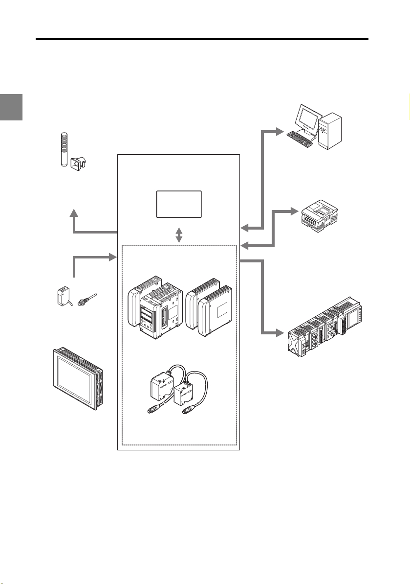
System Configuration
The LK-CC100 and LK-DN100 can be used along with commercially-available devices for
various purposes.
1
Enables control and measured
value reading through RS-232C
communication or the parallel
I/O board of the PC.
Indicator, buzzer
Issues an alarm depending
on the comparator result
output.
LK-G5000 Series
LK Navigator2
*2
Programmable logic controller
(PLC)
Enables synchronization control
of the measurement and
program number switching as
well as reading of control output
and measured values.
Recorder
Records the measurement
result.
Photoelectric sensors,
proximity sensors
Use to send timing input signals
when the measurement object is
detected.
Dedicated touch panel
LK-HD1001
Setup support software (LK-H2)
USB/RS-232C/
Ethernet
Head expansion unit
LK-HA100
OUT1
HIGOLO
LK-HD500
OUT2
TIM
HIGOLO TIM
HEAD1
HEAD2
LASER ON
LASER ON
S
TABILITY
S
TABILITY
BRIGHT D
P
R
O
BRIGHT
G
R
A
ARK
M
D
ARK
SET
ZE
RO
ENT
Controller
LK-G5001V/LK-G5001PV
*1
Expansion unit
LK-CC100
LK-DN100
Head (12 heads max.)
*1: The single unit type controller (LK-G5001V/LK-G5001PV) can be separated into the display panel
and controller unit. They can also be purchased separately.
The single unit type controller is labeled as LK-HD500 on the display panel side and as LK-G5001
or LK-G5001P on the terminal panel side.
*2: Refer to the LK-Navigator 2 User's Manual (the PDF file is on the CD-ROM) for further details on the
setup support software (LK-H2) LK-Navigator 2.
1-2
Page 9

Checking the Package Contents
MS
NS
10
(
FG
)
LK-D
N100
1
B R
A
TE
V
+
CAN H
SHIELD
CAN L
V
-
STATION No.
LK-CC100 (CC-Link communication unit)
1 Before Use
CC-Link communication unit
LK-CC100: 1
User's Manual: 1 Resistors
• 110 1/2W: 2
• 130 1/2W: 2
100
LK-CC
L RUN
SD
RD
L ERR
10
STATION No.
1
TE
A
B R
MODE
)
FG
(
SLD
DG
DB
DA
LK-DN100 (DeviceNet communication unit)
DeviceNet communication unit
LK-DN100: 1
User's Manual: 1 Metal-film resistor
121 1% 1/4W: 2
Screwdriver: 1
Screwdriver: 1
1
The package contents have been carefully inspected; however, if any component is
defective or damaged, contact your nearest KEYENCE office (address listed at the end of
this manual).
1-3
Page 10

1 Before Use
Part Names and Functions
This section describes the name and functions of each component.
1
CC-Link communication unit LK-CC100
L RUN (Operating status) indicator
• Lit: Data communication between the master and local
stations (when lit green).
• Unlit: Data communications timed out (indicator will
light up again when data is received normally).
SD (Send data) indicator
• Lit: Sending data.
RD (Receive data) indicator
• Lit: Receiving data.
L ERR (error) indicator
• Lit: A communications error exists (when lit red).
LK-CC100
L RUN
L ERR
3
2
4
1
0
9
7
8
3
2
4
1
0
9
7
8
3
2
4
1
0
9
7
8
5
4
6
3
7
2
1
0
F
B
E
C
D
SD
RD
5
10
6
5
1
6
STATION No.
5
B RATE
6
8
9
MODE
A
(FG)
SLD
DG
DB
A
D
• Flashing at regular intervals: Station number or
communication speed change detected while power
was on.
• Flashing irregularly: Terminator (terminating resistor) is set incorrectly, or noise is
affecting the unit or CC-Link dedicated cable.
• Unlit: Communications are normal.
STATION No. setting switch
Sets the station number (setting range: 1 to 64). x10 indicates the tens place, x1 indicates
the ones place.
B RATE setting switch
Sets the baud rate. The baud rate settings can be set as follows.
0: 156 kbps, 1: 625 kbps, 2: 2.5 Mbps, 3: 5 Mbps, 4: 10 Mbps
MODE setting switch
Sets the communication mode. The communication mode settings can be set as follows.
햲
햳
햴
햵
햶
햷
햸
햹
햺
Switch setting Multiple Station Ver si on Remark
0 1 1 - Not supported (Disables control input, tolerance comparison
and readout of measurement values for any OUT).
1 1 2 1.1 Disables control input, tolerance comparison and readout of
measurement values for OUT03 and higher.
2 1 3 1.1 Disables control input, tolerance comparison and readout of
measurement values for OUT05 and higher.
1-4
Page 11

1 Before Use
Switch setting Multiple Station Ve rsi on Remark
3 1 4 1.1 Disables control input, tolerance comparison and readout of
measurement values for OUT07 and higher.
4 2 1 2.0 Disables control input or tolerance comparison for any OUT,
and disables readout of measurement values for OUT3 and
higher.
5 2 2 2.0 Disables control input or tolerance comparison for OUT05
and on, and disables readout of measurement values for
OUT07 and higher.
6 2 3 2.0 Disables control input or tolerance comparison for OUT09
and on, and disables readout of measurement values for
OUT11 and higher.
7 2 4 2.0 Unused.
8 4 1 2.0 Disables control input or tolerance comparison for OUT03
and on, and disables readout of measurement values for
OUT07 and higher.
9 4 2 2.0 Disables control input and tolerance comparison for OUT11
and higher.
A 4 3 2.0 Unused.
B 4 4 - Cannot be used due to stress placed on network.
C 8 1 2.0 Disables control input and tolerance comparison for OUT07
and higher.
D 8 2 2.0 Unused.
E 8 3 - Cannot be used due to stress placed on network.
F 8 4 - Cannot be used due to stress placed on network.
1
Connector
Termina l bl ock
Ter minal name Function
FG Functional ground terminal.
Ground to a ground resistance of 100 ohms or less.
SLD Shield.
Connect shield wire from the dedicated CC-Link cable supporting Ver. 1.10
(OP-79426, OP-79427, etc.).
DG Communication ground
DB Communication signal Low
DA Communication signal High
1-5
Page 12

1 Before Use
DeviceNet communication unit LK-DN100
MS (Status) indicator
Displays the status of the LK-DN100.
• Lit green: Normal operation.
1
LK-DN100
MS
NS
• Lit red: An unrecoverable alarm exists (caused when
3
2
wrong switches are selected at start up).
• Flashing red: A recoverable alarm exists (can be
caused by turning the rotary switch after start up). Reset
4
1
5
0
10
6
9
7
8
3
2
4
1
5
0
1
6
9
7
Node Address
8
5
4
6
3
7
2
8
1
Data
9
0
A
F
B
Rate
E
C
D
error by returning the switch where it was at start up.
+
• Unlit: The power is OFF.
NS (Network status) indicator
Displays the status of the network communication.
• Lit green: Slave unit is online and connected to the
V
CAN H
SHIELD
CAN L
V
-
(FG)
master unit.
• Flashing green: Slave unit is online but not connected
to the master unit.
• Lit red: Indicates the bus is off, a duplicate node address exists, or the wrong switches
were selected at start up.
• Flashing red: 1 or more connections have timed out.
• Alternately flashing red and green: A network access error exists.
• Unlit: The power is OFF.
Node Address (node address setting) switch
Sets the node address (setting range: 0 to 63, default setting: 63). x10 indicates the tens
place, x1 indicates the ones place.
햲
햳
햴
햵
햶
햷
햸
Data Rate (baud rate) setting switch
Sets the baud rate. The baud rate settings can be set as follows.
0: 125 kbps, 1: 250 kbps, 2 (default): 500 kbps
Connector
Terminal block
Terminal name Wire color Function
V+ Red Communication power supply (24 VDC input)
CAN_H White Communication signal High
Shield Exposed Shield
CAN_L Blue Communication signal Low
V- Black Communication power supply (0 VDC input)
F.G. terminal
1-6
Page 13
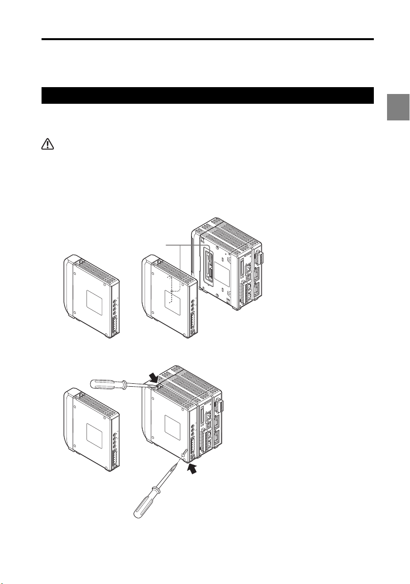
Mounting/Connecting the Units
Connecting the communication unit
1 Before Use
Connect the LK-CC100 CC-Link communication unit or the LK-DN100 DeviceNet
communication unit to the controller.
CAUTION
Turn off the power of the LK-G5000 Series before connecting the communication unit. Otherwise, you
may suffer a shock or damage the unit.
Connect the communication unit by aligning its connector to the connector on
1
the left side of the LK-G5000.
You need to remove the sticker attached to the left side of the LK-G5000 beforehand.
Connector
LK-CC100
L RUN
SD
RD
L ERR
10
STATION No.
1
ATE
B R
MODE
)
FG
(
SLD
DG
LK-CC100
DB
DA
or
LK-DN100
Secure the communication unit by tightening the two connecting screws.
2
LK-DN100
MS
NS
10
STATION No.
1
B RATE
+
V
CAN H
SHIELD
CAN L
V
)
FG
(
Screw position
LK-G5000
)
V
(
)
A
(
0V
)
1
V
(
LASER ON
)
A
(
0V
21
22
2
23
1
1
24
2
25
ETHERNET
3
26
LK-DN100
4
27
5
MS
28
6
29
7
30
8
31
HEAD
NS
2
9
32
10
33
11
34
12
35
13
36
14
LK-CC100
RUN
L
SD
RD
L ERR
10
STATION No.
1
ATE
B R
MODE
)
FG
(
SLD
DG
DB
DA
LK-CC100
or
LK-DN100
37
15
38
USB
16
39
17
40
18
19
20
10
STATION No.
1
HEAD
1
RS-232C
TE
A
B R
COM INZERO 1TIMING 1GOLASER 1DC 24V
+
V
DISPLAY
CAN H
SHIELD
CAN L
V
)
FG
(
LK-G5000
)
V
(
)
A
(
0V
)
1
V
(
LASER ON
)
A
(
0V
21
22
2
23
1
1
24
2
25
ETHERNET
3
26
4
27
5
28
6
29
7
30
8
31
HEAD
2
9
32
10
33
11
34
12
35
13
36
14
37
15
38
USB
16
39
17
40
18
19
20
HEAD
1
RS-232C
COM INZERO 1TIMING 1GOLASER 1DC 24V
AY
DISPL
1
Screw position
Tightening torque
Limit the tightening torque to 0.7 Nm or less.
1-7
Page 14

1
1 Before Use
1-8
Page 15

Connecting to CC-Link2
Typical CC-Link System Configuration............................. 2-2
Connecting to the Field Network....................................... 2-4
Changing the CC-Link Communication Unit Settings..... 2-7
Creating the Ladder Program ...........................................2-19
Timing Diagrams .............................................................. 2-21
2
2-1
Page 16
2 Connecting to CC-Link
Host device: PLC, etc.
(CC-Link master unit)
LK-G5001
+
LK-CC100
LK-G5001
+
LK-CC100
LK-G5001
+
LK-CC100
Terminator
connection
for KV-CL20,
etc.
RS-232C/USB/Ethernet
1
1
2
3
4
5
6
7
8
9
10
11
12
13
14
15
16
17
18
19
20
2
21
22
23
24
25
26
27
28
29
30
31
32
33
34
35
36
37
38
39
40
LASER ON
ETHERNET
USB
DISPL
AY
R
S-232C
H
EA
D
1
(
V
)
(
A
)
0V
(
V
)
(
A
)
0V
COM INZERO 1TIMING 1GOLASER 1DC 24V
1
H
EA
D
LK-G5000
2
L
R
UN
SD
RD
L ERR
10
LK-CC100
1
B R
A
TE
SLD
DG
DB
DA
MODE
STATION No.
(
FG
)
1
1
2
3
4
5
6
7
8
9
10
11
12
13
14
15
16
17
18
19
20
2
21
22
23
24
25
26
27
28
29
30
31
32
33
34
35
36
37
38
39
40
LASER ON
ETHERNET
USB
DISPLA
Y
R
S
-232C
H
EA
D
1
(
V
)
(
A
)
0V
(
V
)
(
A
)
0V
COM INZERO 1TIMING 1GOLASER 1DC 24V
1
H
EA
D
LK-G5000
2
L
R
UN
SD
RD
L ERR
10
LK-CC100
1
B R
A
TE
SLD
DG
DB
DA
MODE
STATION No.
(
FG
)
1
1
2
3
4
5
6
7
8
9
10
11
12
13
14
15
16
17
18
19
20
2
21
22
23
24
25
26
27
28
29
30
31
32
33
34
35
36
37
38
39
40
LASER ON
ETHERNET
USB
DISPLA
Y
R
S-232C
H
EA
D
1
(
V
)
(
A
)
0V
(
V
)
(
A
)
0V
COM INZERO 1TIMING 1GOLASER 1DC 24V
1
H
EA
D
LK-
G5000
2
L
R
UN
SD
RD
L ERR
10
LK-CC100
1
B R
A
TE
SLD
DG
DB
D
A
MODE
STATION No.
(
FG
)
LK-H02*/H05*
series head
LK-H02*/H05*
series head
Terminator
Max. connections:
64 units
LK-H02*/H05*
series head
PC for setup
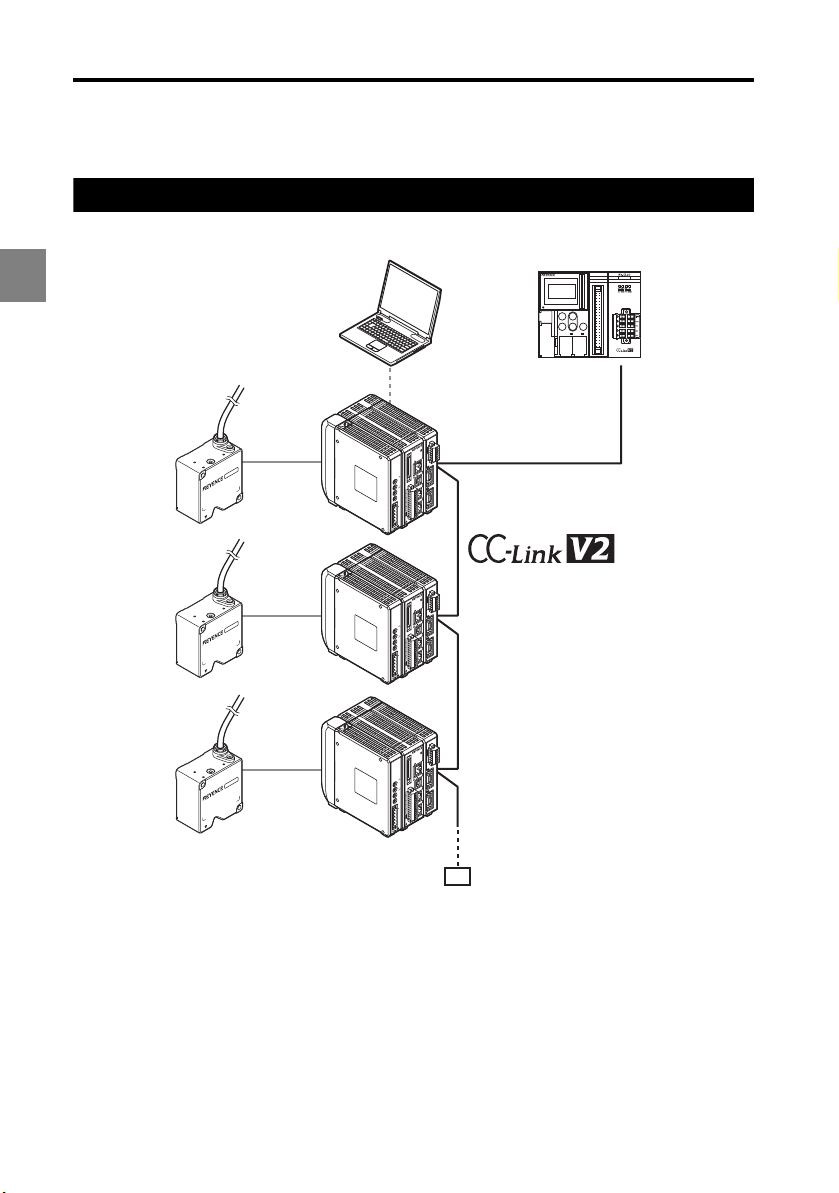
Typical CC-Link System Configuration
Typical system configuration using CC-Link
2
2-2
Page 17
2 Connecting to CC-Link
Special notes for using a CC-Link system
Take note of the following when using the LK-CC100 in a CC-Link network.
• The LK-CC100 is a network controller for CC-Link Ver. 2.00 or Ver. 1.10. If using the LKCC100 on a CC-Link Ver. 2.00 network, it must be connected to a master device
compatible with CC-Link Ver. 2.00. The LK-CC100 operates as a Ver. 1.10 unit when the
extended cyclic setting is set to single. It operates as a Ver. 2.00 unit at double or faster.
• CC-Link supports up to 64 connected devices. The actual number of devices that can
be connected is limited by the number of stations each unit occupies. Refer to the
manual for the master device used on the CC-Link to determine the number of stations
occupied and the maximum number of devices that can be connected.
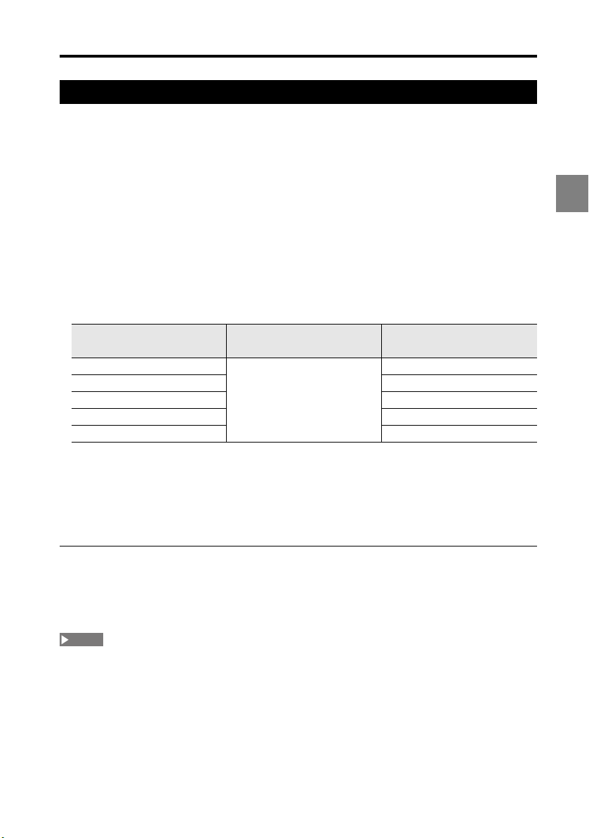
• The maximum total length of the entire CC-Link network is 1.2 km (at 156 kbps). Refer to
the following table for the relation between communication speed and maximum cable
length.
2
Communication speed Cable length between
stations
156 kbit/s 20 cm min. 1,200 m
625 kbit/s 900 m
2.5 M bit/s 400 m
5 M bit/s 160 m
10 M bit/s 100 m
• Connect the LK-CC100 using the dedicated CC-Link cable (Ver. 1.10 or higher).
• Always connect a terminator (110 ohms 1/2W) between DA - DB on the units at both
ends of the CC-Link.
• The setup support software LK-Navigator 2 (LK-H2) cannot be used to display received
light waveforms through the CC-Link.
Maximum total cable
length
Precautions on CC-Link settings
• The parameters for the LK-CC100 should be set to match the CC-Link master unit. Set
using the STATION No. setting switch, B RATE setting switch, and MODE setting switch.
• Refer to the manual for the CC-Link master unit for details on how to set it.
NOTE
The number of stations occupied must be set according to the data read/write size.
2-3
Page 18

2 Connecting to CC-Link
Approx. 8 mm
Twist conductor strands together
Connecting to the Field Network
To connect to the master device or network controller on the field network using a
multidrop connection, or to connect other slave devices, connect a communication cable
that supports each field network to the field network connector.
2
Preparing the communication cable
Use a communication cable dedicated for CC-Link (Ver. 1.10 or higher).
Remove the sheath (outer insulation) from the cable.
1
Approx. 50 mm
Sheath (outer insulation)
Carefully remove about 50 mm from the end of the dedicated cable so as not to
damage the braided shield wires.
Prepare the shield.
2
Aluminum polyester laminated tape
Carefully unravel the braided shield wires. Inside the shield is a single exposed
drain wire (twisted or loose). Twist this with the unraveled shield wire and cover it
with an insulation tube.
Strip the insulation from the signal lines.
3
Shield (braided shield wire)
Twisted shield wireInsulation tube
Being careful not to damage the signal lines, remove the aluminum polyester
laminated tape and filling, and strip about 8 mm from each signal line.
Twist the exposed conductor strands to keep them together.
2-4
Page 19

2 Connecting to CC-Link
Connecting the wiring cable
Connect the prepared wiring cable to the field network connector (terminal block).
Reference
The field network connector is designed for multidrop connection of slave devices.
Insert each signal line into the holes in the connector.
1
Insert into corresponding connector
NOTE
Before inserting the communication cable, loosen the connector clamp screws.
Secure each signal line by tightening the clamp screws on the side of the
2
connector.
2
Secure by tightening clamp screw
Wiring varies depending on the network controller.
Insert the applicable signal lines into the connector.
2-5
Page 20

2 Connecting to CC-Link
SLD
DG
DB
DA
(FG)
NOTE
Wiring to the CC-Link controller (LK-CC100)
The LK-CC100 field network connector (terminal block) is to be wired as explained below.
Terminal name Funct ion
FG Functional ground terminal.
SLD Shield.
2
DG Communication ground
DB Communication signal Low
DA Communication signal High
• To connect the CC-Link controller to the CC-Link, use the CC-Link dedicated cable (Ver. 1.10 or
higher).
• At each CC-Link station connection, connect the cable shield to FG.
Ground to a ground resistance of 100 ohms or less.
Connect shield wire from the dedicated CC-Link cable
supporting Ver. 1.10 (OP-79426, OP-79427, etc.).
Typical connection
Refer to the manual for the CC-Link master unit for wiring details.
Master station
Terminator Terminator
LK-CC100 Other unit Other unit
Connecting terminators
A terminator must be connected to both ends of the
trunk line. The terminators must be connected to
reduce signal reflection and stabilize communication.
Terminator resistance: 110 ohms, 1/2W
• The terminators must be connected, otherwise, the CC-Link
will not communicate properly.
• If using the CC-Link dedicated high-performance cable,
use a 130 ohm, 1/2W resistor.
2-6
Other unit LK-CC100
DB
Terminator
DA
(FG)
SLD
DG
DB
DA
Page 21

2 Connecting to CC-Link
Changing the CC-Link Communication Unit Settings
This section explains the principle and operation of the CC-Link communication unit (LKCC100).
NOTE
This manual describes only those functions and settings of the CC-Link master device necessary for
communicating with the LK-CC100. Refer to the manual supplied with the master device for details on
functions and settings between the CC-Link master device and a PLC.
Field network connection specifications
Master settings
To connect the LK-CC100 to the CC-Link master, it is necessary to configure the slave
attribute and memory allocation settings.
Slave attributes
Register the LK-CC100 to the CC-Link master unit as a remote device station.
You can also set this by importing a CSP file into the software for the master unit (ladder
programming software, CC-Link setting software).
Memory allocation settings
In order to exchange data between the LK-CC100 and CC-Link master unit, the memory
allocation must be set using the software for the master unit (ladder programming
software, CC-Link setting software).
Reference
• The RX, RY, RWw, and RWr communicated over the CC-Link is stored in the master unit's buffer
memory.
• When multiple slaves are being used, the memory is allocated automatically for each slave
according to the specified starting address. You can view the memory allocation information for
each slave in the CC-Link setting software.
• CSP files can be downloaded from the KEYENCE website.
http://www.keyence.co.jp/
2
2-7
Page 22
2 Connecting to CC-Link
Control using CC-Link
This section explains how to use a PLC to control the LK-CC100 configured for a CC-Link
network.
NOTE
This section describes only those functions and settings of the CC-Link master station necessary for
communicating with the LK-CC100. Refer to the manual supplied with the CC-Link master station and
2
PLC for details on functions and settings of each device.
Operation and memory configuration with CC-Link
On a CC-Link network, the LK-CC100 operates as a slave station (remote device station)
to the CC-Link master station connected via the network cable.
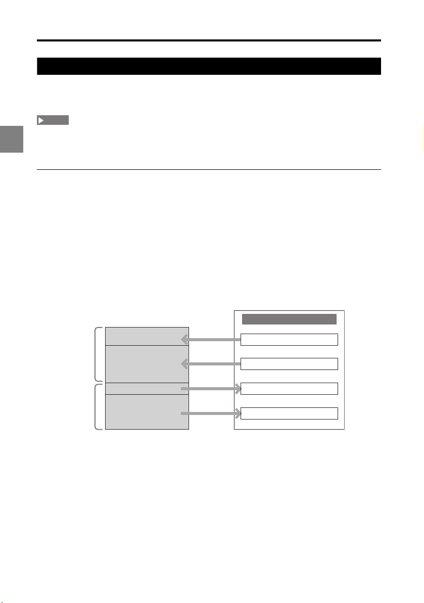
• The buffer memory inside the LK-CC100 is linked to remote I/O and remote registers on
the CC-Link master station according to the memory configuration illustrated below.
• Control the system by setting and programming (2-14) according to this memory
configuration.
Memory configuration
Buffer memory inside the LK-CC100 is linked as shown here.
Read buffer
Write buffer
2-8
Buffer memory
Read control buffer
Read data buffer
Write control buffer
Write data buffer
CC-Link master station
RY (remote outputs)
RWw (remote registers)
RX (remote inputs)
RWr (remote registers)
Page 23

2 Connecting to CC-Link
RY (Remote outputs)
RY (remote outputs) are control signals sent from the CC-Link master station to the LK-CC100.
LKCC100
Read
control
buffer
Signal
direction
CC-Link master station
RY
(Remote outputs)
RY (n+0) CHG_PRG_REQ • Requests to change to the program
RY (n+1) System reserved
RY (n+2) SYNC_TIM_ON_REQ • Requests synchronized timing ON at
RY (n+3) System reserved
RY (n+4) SYNC_TIM_OFF_REQ • Requests synchronized timing OFF at
RY (n+5) System reserved
RY (n+6) SYNC_ZERO_ON_REQ • Requests synchronized zero ON at the
RY (n+7) System reserved
RY (n+8) SYNC_ZERO_OFF_REQ • Requests synchronized zero OFF at
RY (n+9) System reserved
RY (n+10) SYNC_RESET_REQ • Requests synchronized reset at the
RY (n+11) System reserved
RY (n+12) System reserved
RY (n+13) System reserved
RY (n+14) System reserved
RY (n+15) System reserved
RY (n+16*m+0) System reserved
RY (n+16*m+1) System reserved
RY (n+16*m+2) System reserved
Signal name Explanation
number stored in SET_PRG_NUM at
the rising edge from OFF (0) ON (1).
• Ends the request at the falling edge
from ON (1) OFF (0).
the rising edge from OFF (0) ON (1).
• Ends the request at the falling edge
from ON (1) OFF (0).
the rising edge from OFF (0) ON (1).
• Ends the request at the falling edge
from ON (1) OFF (0).
rising edge from OFF (0) ON (1).
• Ends the request at the falling edge
from ON (1) OFF (0).
the rising edge from OFF (0) ON (1).
• Ends the request at the falling edge
from ON (1) OFF (0).
rising edge from OFF (0) ON (1).
• Ends the request at the falling edge
from ON (1) OFF (0).
2
2-9
Page 24

2 Connecting to CC-Link
LKCC100
Read
control
buffer
2
Signal
direction
CC-Link master station
RY
(Remote outputs)
RY (n+16*m+3) OUTm_TIM_ON_REQ • Requests timing ON to OUTm at the
RY (n+16*m+4) System reserved
RY (n+16*m+5) OUTm_TIM_OFF_REQ • Requests timing OFF to OUTm at the
RY (n+16*m+6) System reserved
RY (n+16*m+7) System reserved
RY (n+16*m+8) OUTm_ZERO_ON_REQ • Requests zero ON to OUTm at the
RY (n+16*m+9) System reserved
RY (n+16*m+10) OUTm_ZERO_OFF_REQ • Requests zero OFF to OUTm at the
RY (n+16*m+11) System reserved
RY (n+16*m+12) System reserved
RY (n+16*m+13) OUTm_RESET_REQ • Requests reset to OUTm at the rising
RY (n+16*m+14) System reserved
RY (n+16*m+15) System reserved
RY (n+16*13+0) System reserved
.
.
.
Signal name Explanation
rising edge from OFF (0) ON (1).
• Ends the request at the falling edge
from ON (1) OFF (0).
rising edge from OFF (0) ON (1).
• Ends the request at the falling edge
from ON (1) OFF (0).
rising edge from OFF (0) ON (1).
• Ends the request at the falling edge
from ON (1) OFF (0).
rising edge from OFF (0) ON (1).
• Ends the request at the falling edge
from ON (1) OFF (0).
edge from OFF (0) ON (1).
• Ends the request at the falling edge
from ON (1) OFF (0).
System reserved
• n: varies according to the station number of the LK-CC100.
• m (1 to 12): corresponds to the OUT number. m = 1 for OUT01, m = 2 for OUT02, etc.
2-10
Page 25

2 Connecting to CC-Link
RWw (Remote registers)
RWw (remote registers) refers to the area where parameters sent from the CC-Link master
station to the LK-CC100 are stored.
LKCC100
Read
data
buffer
n: varies according to the station number of the LK-CC100.
Signal
direction
CC-Link master station
RY
(Remote outputs)
RWw (n+0) SET_PRG_NUM Sets the program selection number from
RWw (n+1) System reserved
.
.
.
Signal name Explanation
0 to 7.
System reserved
RY (Remote inputs)
RX (remote inputs) refers to the area where LK-CC100 statuses and responses to RY
(remote output) control signals are stored.
LKCC100
Write
control
buffer
Signal
direction
CC-Link master station
RY
(Remote outputs)
RX (n+0) CHG_PRG_ACQ Turns ON (1) when the program number
RX (n+1) CHG_PRG_ERR Turns ON (1) when an error occurs during
RX (n+2) SYNC_TIM_ON_ACQ Turns ON (1) when the synchronized
RX (n+3) SYNC_TIM_ON_ERR Turns ON (1) when an error occurs during
RX (n+4) SYNC_TIM_OFF_ACQ Turns ON (1) when the synchronized
RX (n+5) SYNC_TIM_OFF_ERR Turns ON (1) when an error occurs during
RX (n+6) SYNC_ZERO_ON_ACQ Turns ON (1) when the synchronized zero
RX (n+7) SYNC_ZERO_ON_ERR Turns ON (1) when an error occurs during
RX (n+8) SYNC_ZERO_OFF_ACQ Turns ON (1) when the synchronized zero
RX (n+9) SYNC_ZERO_OFF_ERR Turns ON (1) when an error occurs during
RX (n+10) SYNC_RESET_ACQ Turns ON (1) when the synchronized
RX (n+11) SYNC_RESET_ERR Turns ON (1) when an error occurs during
RX (n+12) System reserved
Signal name Explanation
changeover process completes.
the program number changeover
process.
timing ON process completes.
the synchronized timing ON process.
timing OFF process completes.
the synchronized timing OFF process.
ON process completes.
the synchronized zero ON process.
OFF process completes.
the synchronized zero OFF process.
reset process completes.
the synchronized reset process.
2
2-11
Page 26

2 Connecting to CC-Link
2
LKCC100
Write
control
buffer
Signal
direction
CC-Link master station
RY
(Remote outputs)
RX (n+13) CHG_PRG_ENBLE Turns ON (1) when program changeover
RX (n+14) READY_FLAG • Turns ON (1) when the controller is not
RX (n+15) SYSTEM_ERR_FLAG • Turns ON (1) when the controller or
RX (n+16*m+0) OUTm_LO Turns ON (1) when the comparator output
RX (n+16*m+1) OUTm_GO Turns ON (1) when the comparator output
RX (n+16*m+2) OUTm_HI Turns ON (1) when the comparator output
RX (n+16*m+3) OUTm_TIM_ON_ACQ Turns ON (1) when the timing ON process
RX (n+16*m+4) OUTm_TIM_ON_ERR Turns ON (1) when an error occurs during
RX (n+16*m+5) OUTm_TIM_OFF_ACQ Turns ON (1) when the timing OFF
RX (n+16*m+6) OUTm_TIM_OFF_ERR Turns ON (1) when an error occurs during
RX (n+16*m+7) OUTm_TIM_STATE Turns ON (1) when the timing for OUTm is
RX (n+16*m+8) OUTm_ZERO_ON_ACQ Turns ON (1) when the zero ON process
RX (n+16*m+9) OUTm_ZERO_ON_ERR Turns ON (1) when an error occurs during
RX (n+16*m+10) OUTm_ZERO_OFF_ACQ Turns ON (1) when the zero OFF process
RX (n+16*m+11) OUTm_ZERO_OFF_ERR Turns ON (1) when an error occurs during
RX (n+16*m+12) OUTm_ZERO_STATE Turns ON (1) when the zero for OUTm is
RX (n+16*m+13) OUTm_RESET_ACQ Turns ON (1) when the reset process
RX (n+16*m+14) OUTm_RESET_ERR Turns ON (1) when an error occurs during
Signal name Explanation
is possible.
in setting mode, communicating,
running, Able Tuning, or setting scaling
from measurement data.
• When OFF (0), the ***-ERR
corresponding to the ***-REQ turns ON
(1).
expansion unit has a system error.
• When ON (1), all signals except
SYSTEM_ERR_NO become invalid.
for OUTm is LO.
for OUTm is GO.
for OUTm is HI.
for OUTm completes.
the timing ON process for OUTm.
process for OUTm completes.
the timing OFF process for OUTm.
ON.
for OUTm completes.
the zero ON process for OUTm.
for OUTm completes.
the zero OFF process for OUTm.
ON.
completes for OUTm.
the reset process for OUTm.
2-12
Page 27

2 Connecting to CC-Link
LKCC100
Write
control
buffer
Signal
direction
CC-Link master station
RY
(Remote outputs)
RX (n+16*m+15) System reserved
RX (n+16*13+0) System reserved
.
.
.
Signal name Explanation
System reserved
• n: varies according to the station number of the LK-CC100.
• m (1 to 12): corresponds to the OUT number. m = 1 for OUT01, m = 2 for OUT02, etc.
• ***-ACQ and ***-ERR turn OFF (0) at the falling edge of ***-REQ from ON(1) OFF(0).
RWr (Remote registers)
RWr (remote registers) refers to the area where the statuses of LK-CC100 are stored.
LKCC100
Write
data
buffer
• n: varies according to the station number of the LK-CC100.
• m (1 to 12): corresponds to the OUT number. m = 1 for OUT01, m = 2 for OUT02, etc.
Signal
direction
CC-Link master station
RY
(Remote outputs)
RWr (n+0) CUR_PRG_NUM Stores the current program selection
RWr (n+1) SYSTEM_ERR_NO Stores the system error number when the
RWr (n+2) COUNTER_LO Stores the unsigned 32-bit counter value.
RWr (n+3) COUNTER_HI
RWr
(n+2*(m+1)+0)
RWr
(n+2*(m+1)+1)
RWr
(n+2*(13+1)+0)
.
.
.
Signal name Explanation
number from 0 to 7.
SYSTEM_ERR_FLAG turned ON (1).
Increments the count each time a
measurement value is acquired from the
controller.
OUTm_LO Stores the measurement value for OUTm.
OUTm_HI
System reserved
System reserved
* This register assumes the following
values in these instances:
Comparator standby = 0xFFF00000
Alarm = 0x000FFFFF
- Range over = 0xFFF00001
+ Range over = 0x000FFFFE
2
2-13
Page 28

2 Connecting to CC-Link
Setting and programming
The following settings and program are required to control the LK-CC100 using CC-Link.
2
Set communication
conditions
Set data size
Ladder program
Set the LK-CC100 communication speed and slave ID (station number).
Calculate and set the data size required for communication. Refer to
"Link" (Page 2-14) for details.
On the CC-Link master station, set the link area for the LK-CC100.
Create a program according to the settings.
Using handshake signals, create a program to receive command
signals and operation result data for commands from the host PLC.
Execute program
Communication condition settings
Set the communication speed and slave ID (station number) on the LK-CC100 using the
STATION No. setting switch and B RATE setting switch.
• Slave ID (station number): set to the same number as the slave ID (station number)
assigned to the LK-CC100 in the CC-Link.
• Baud rate: Set to the same speed as the baud rate (communication speed) in the CCLink.
Refer to the manual for the CC-Link master station for details on setting the CC-Link
master station.
Data size settings
Set the write size and read size of the memory to be linked in the CC-Link using the MODE
setting switch. This is set as a combination of the "number of stations occupied" and the
"extended cyclic multiple". Use the table below to calculate.
Occupies 1 station Occupies 2 stations Occupies 3 stations Occupies 4 stations
x1 Setting impossible RX/RY: 64 bits
x2 RX/RY: 32 bits
RWw/RWr: 16 bytes
x4 RX/RY: 64 bits
RWw/RWr: 32 bytes
x8 RX/RY: 128 bits
RWw/RWr: 64 bytes
RWw/RWr: 16 bytes
RX/RY: 96 bits
RWw/RWr: 32 bytes
RX/RY: 192 bits
RWw/RWr: 64 bytes
RX/RY: 384 bits
RWw/RWr: 128 bytes
RX/RY: 96 bits
RWw/RWr: 24 bytes
RX/RY: 160 bits
RWw/RWr: 48 bytes
RX/RY: 320 bits
RWw/RWr: 96 bytes
Setting impossible Setting impossible
RX/RY: 128 bits
RWw/RWr: 32 bytes
RX/RY: 224 bits
RWw/RWr: 64 bytes
Setting impossible
2-14
Page 29

2 Connecting to CC-Link
Memory allocation example
This example shows how to make the following settings.
Memory allocation
This example assumes the CC-Link master station has the following memory allocation
settings.
KEYENCE PLC Mitsubishi Electric
RX (remote input) refresh device R32000 X1000 Bits
RWw (remote register) refresh
device
RX (remote output) refresh device R33000 Y1000 Bits
RWr (remote register) refresh device DM10500 D2000 Words (16
DM10700 D1000 Words (16
PLC
Operation
This example performs the following measurements and control inputs.
• Measurement acquisition from OUT1 to OUT4
• Control inputs for OUT1 to OUT4
• Program change
Reference
• The data memory allocated in the PLC must be set larger area than the CC-Link communication
size.
• For example, to communicate X bytes from the PLC to the LK-CC100, and Y bytes from the LKCC100 to the PLC, allocate X bytes or more PLC data memory for output, and Y bytes or more for
input. Otherwise, an error will occur if not enough memory is allocated.
Device units
bits)
bits)
2
2-15
Page 30

2 Connecting to CC-Link
Example for a KEYENCE PLC
LK-CC100 Signal
direction
Read control buffer R32000 CHG_PRG_REQ
2
Read data buffer DM10700 SET_PRG_NUM
Write control buffer R33000 CHG_PRG_ACQ
CC-Link master station
Device Signal name
R32001
R32002 SYNC_TIM_ON_REQ
R32003
R32004 SYNC_TIM_OFF_REQ
R32005
R32006 SYNC_ZERO_ON_REQ
R32007
.
.
.
R32408 OUT4_ZERO_ON_REQ
R32409
R32410 OUT4_ZERO_OFF_REQ
R32411
R32412
R32413 OUT4_RESET_REQ
R32414
R32415
R33001 CHG_PRG_ERR
R33002 SYNC_TIM_ON_ACQ
R33003 SYNC_TIM_ON_ERR
R33004 SYNC_TIM_OFF_ACQ
R33005 SYNC_TIM_OFF_ERR
R33006 SYNC_ZERO_ON_ACQ
R33007 SYNC_ZERO_ON_ERR
.
.
.
R33408 OUT4_ZERO_ON_ACQ
R33409 OUT4_ZERO_ON_ERR
R33410 OUT4_ZERO_OFF_ACQ
R33411 OUT4_ZERO_OFF_ERR
R33412 OUT4_ZERO_STATE
R33413 OUT4_RESET_ACQ
R33414 OUT4_RESET_ERR
R33415
.
.
.
.
.
.
2-16
Page 31

2 Connecting to CC-Link
LK-CC100 Signal
direction
Write data buffer DM10500 CUR_PRG_NUM
CC-Link master station
Device Signal name
DM10501 SYSTEM_ERR_NO
DM10502 COUNTER_LO
DM10503 COUNTER_HI
DM10504 OUT1_LO
DM10505 OUT1_HI
.
.
.
DM10510 OUT4_LO
DM10511 OUT4_HI
Example for a Mitsubishi Electric PLC
LK-CC100 Signal
direction
Read control buffer Y1000 CHG_PRG_REQ
Read data buffer D1000 SET_PRG_NUM
CC-Link master station
Device Signal name
Y1001
Y1002 SYNC_TIM_ON_REQ
Y1003
Y1004 SYNC_TIM_OFF_REQ
Y1005
Y1006 SYNC_ZERO_ON_REQ
Y1007
.
.
.
Y1048 OUT4_ZERO_ON_REQ
Y1049
Y104A OUT4_ZERO_OFF_REQ
Y104B
Y104C
Y104D OUT4_RESET_REQ
Y104E
Y104F
2
.
.
.
.
.
.
2-17
Page 32

2 Connecting to CC-Link
LK-CC100 Signal
direction
Write control buffer X1000 CHG_PRG_ACQ
2
Write data buffer D2000 CUR_PRG_NUM
CC-Link master station
Device Signal name
X1001 CHG_PRG_ERR
X1002 SYNC_TIM_ON_ACQ
X1003 SYNC_TIM_ON_ERR
X1004 SYNC_TIM_OFF_ACQ
X1005 SYNC_TIM_OFF_ERR
X1006 SYNC_ZERO_ON_ACQ
X1007 SYNC_ZERO_ON_ERR
.
.
.
X1048 OUT4_ZERO_ON_ACQ
X1049 OUT4_ZERO_ON_ERR
X104A OUT4_ZERO_OFF_ACQ
X104B OUT4_ZERO_OFF_ERR
X104C OUT4_ZERO_STATE
X104D OUT4_RESET_ACQ
X104E OUT4_RESET_ERR
X104F
D2001 SYSTEM_ERR_NO
D2002 COUNTER_LO
D2003 COUNTER_HI
D2004 OUT1_LO
D2005 OUT1_HI
.
.
.
D2010 OUT4_LO
D2011 OUT4_HI
.
.
.
.
.
.
2-18
Page 33

2 Connecting to CC-Link
Creating the Ladder Program
Acquiring measurement data, tolerance comparator results, various
statuses (auto-zero, timing, system error), and program number settings
Create the ladder program as follows.
Check the status.
1
Verify the SYSTEM_ERR_FLAG is OFF and READY_FLAG is ON.
Store the counter value.
2
Store the current counter value (COUNTER_LO and COUNTER_HI).
Check for counter value updates.
3
Wait until the current counter value, stored in Step 2, changes.
Acquire data.
4
Acquire the required data.
NOTE
The counter value will be updated twice after any of the following has happened to the controller: start
up, set, an able tuning performed, a set scaling from a measurement data, or a complete
communication has been performed
2
2-19
Page 34

2 Connecting to CC-Link
Reference
Programming a control input
Create the ladder program as follows.
Check the status.
1
• Verify the SYSTEM_ERR_FLAG is OFF and READY_FLAG is ON.
• To request a program change, verify CHG_PRG_ENBLE is ON.
2
• Verify ***_ACQ is OFF.
Set the control parameter.
2
To request a program change, store the program number in SET_PRG_NUM.
Send the control input request.
3
Change the request signal to control ***_REQ from OFF -> ON.
The request is sent to the LK-CC100 at the rising edge of ***_REQ.
Check the control input status.
4
When the LK-CC100 receives the control input and completes the execution
requested, ***_ACQ turns ON.
When ***_ACQ turns ON, verify ***_ERR and make sure the request was processed
normally.
Check the control input result.
5
• For a program change request, wait for CUR_PRG_NUM to change.
• For a control request that causes ***_STATE to change, wait for ***_STATE to
change.
• For all other requests, wait for input response time (T2).
Refer to the LK-G5000 series User's Manual for details on input response time (T2).
Disable the control input request.
6
Disable the control input request by changing ***_REQ from ON OFF.
Store the counter value.
7
Store the current counter value (COUNTER_LO and COUNTER_HI).
Check for counter value updates.
8
Wait until the current counter value, stored in Step 7, changes.
Acquire data.
9
Acquire the required data.
2-20
Page 35

Timing Diagrams
This is the timing diagram for a control input.
•OUT: Master slave
•IN: Slave master
• Internal: Internal processing at the slave
2 Connecting to CC-Link
NOTE
• Control inputs that do not have the ***_STATE flag follow the same timing except that the ***_STATE
flag is omitted.
• The X axis shows the correct timing but not the exact time.
Normal timing (status change from OFF ON)
Verify ***_ACQ is OFF, then turn ***_REQ ON.
1 ***_REQ OUT
2 Internal
processing
3 ***_ACQ
4 ***_ERR IN
5 ***_STATE IN
IN
Abnormal timing (error, status stays ON)
1 ***_REQ OUT
Verify ***_ACQ is OFF, then turn ***_REQ ON.
Issue the next ***_REQ after
verifying ***_ACQ has gone LO.
2
2 Internal
processing
3 ***_ACQ IN
4 ***_ERR IN
5 ***_STATE IN
***_ACQ turns ON after
***_ERR changes state.
***_ERR changes to the OFF state at the
same time ***_ACQ turns OFF.
***_STATE does not change if ***_ERR goes to HI
because no processing is performed.
2-21
Page 36

2 Connecting to CC-Link
Internal processing time
***_REQ ON ***_ACQ ON
t
The following table describes time t for each command.
2
Control input Signal name t
Program change input CHG_PRG_REQ 200 ms + number of expansion units x 130 ms
Timing input SYNC_TIM_ON_REQ
Zero input SYNC_ZERO_ON_REQ
Reset input SYNC_RESET_REQ
Counter update interval = 45 ms
Reference
The response speed becomes slower than the figures in the table during communication with the LKNavigator 2 setup support software or during communication with the RS-232C port.
SYNC_TIM_OFF_REQ
OUT_TIM_ON_REQ
OUT_TIM_OFF_REQ
SYNC_ZERO_OFF_REQ
OUT_ZERO_ON_REQ
OUT_ZERO_OFF_REQ
OUT_RESET_REQ
60 ms
2-22
Page 37

Connecting to DeviceNet3
Typical DeviceNet System Configuration......................... 3-2
Connecting to the Field Network....................................... 3-4
Changing the DeviceNet Communication Unit Settings . 3-7
Creating the Ladder Program ...........................................3-18
Timing Diagrams .............................................................. 3-20
3
3-1
Page 38

3 Connecting to DeviceNet
Terminator
connection
for KV-DN20,
etc.
Communication
power supply
PC for setup
Host device: PLC, etc.
(DeviceNet master unit)
LK-G5001
+
LK-DN100
LK-G5001
+
LK-DN100
LK-G5001
+
LK-DN100
Terminator
Max. connections: 64 units
(Including master node)
RS-232C/USB/Ethernet
LK-H02*/H05*
series head
LK-H02*/H05*
series head
LK-H02*/H05*
series head
1
1
2
3
4
5
6
7
8
9
10
11
12
13
14
15
16
17
18
19
20
2
21
22
23
24
25
26
27
28
29
30
31
32
33
34
35
36
37
38
39
40
LASER ON
ETHERNET
USB
DISPL
A
Y
R
S-232C
H
EA
D
1
(
V
)
(
A
)
0V
(
V
)
(
A
)
0V
COM INZERO 1TIMING 1GOLASER 1DC 24V
1
H
EA
D
LK-
G5000
2
MS
NS
10
(
FG
)
LK-DN100
1
B RA
TE
V
+
CA
N H
SH
IELD
C
AN
L
V
-
STATION No.
1
1
2
3
4
5
6
7
8
9
10
11
12
13
14
15
16
17
18
19
20
2
21
22
23
24
25
26
27
28
29
30
31
32
33
34
35
36
37
38
39
40
LASER ON
ETHERNET
USB
DISPL
AY
R
S-232C
H
EA
D
1
(
V
)
(
A
)
0V
(
V
)
(
A
)
0V
COM INZERO 1TIMING 1GOLASER 1DC 24V
1
H
EA
D
LK-
G5000
2
MS
NS
10
(
FG
)
LK-DN100
1
B RA
TE
V
+
C
AN
H
SH
IELD
C
AN
L
V
-
STATION No.
1
1
2
3
4
5
6
7
8
9
10
11
12
13
14
15
16
17
18
19
20
2
21
22
23
24
25
26
27
28
29
30
31
32
33
34
35
36
37
38
39
40
LASER ON
ETHERNET
USB
DISPL
AY
R
S-232C
H
EA
D
1
(
V
)
(
A
)
0V
(
V
)
(
A
)
0V
COM INZERO 1TIMING 1GOLASER 1DC 24V
1
H
EA
D
LK-G5000
2
MS
NS
10
(
FG
)
LK-DN100
1
B RA
TE
V
+
C
AN
H
SH
IELD
C
A
N
L
V
-
STATION No.
Typical DeviceNet System Configuration
Typical system configuration using DeviceNet
3
3-2
Page 39

3 Connecting to DeviceNet
Special notes for using a DeviceNet system
Take note of the following when using the LK-DN100 in a DeviceNet network.
• DeviceNet supports up to 64 connected devices. This includes the master, slaves, and
configurable devices.
• The maximum total length of the entire DeviceNet network is 500 m (at 125 kbps). Refer
to the following table for the relation between communication speed and maximum
cable length.
Typ e of
cable
Thick cable 500 kbit/s 100 m 6 m 36 m 8 A
Thin cable 500 kbit/s 100 m 36 m 3 A
• Connect the LK-DN100 using the dedicated 5-wire cable for DeviceNet. KEYENCE will
not guarantee performance if any other cable is used.
• Always connect a terminator (121 ohms, 1% 1/4W metal-film resistor) at both ends of the
trunk line.
• Do not connect any non-DeviceNet components along communication line. Otherwise,
signal reflection and other problems may cause communication failures.
• Only one point on the network must be ground to a ground resistance of 100 ohms or
less. If a ground resistance of 100 ohms or less is not available, do not connect the FG
to the V- on the communication power supply to avoid problems caused by noise.
• Do not connect the shield to multiple locations on the network.
Communication
speed
250 kbit/s 250 m 78 m
125 kbit/s 500 m 156 m
250 kbit/s 100 m 78 m
125 kbit/s 100 m 156 m
Max. length
of network
Branch
lengths
Tot a l b ra nc h
length
Current
capacity
3
Precautions on DeviceNet settings
• Set the LK-DN100 parameters according to the DeviceNet master unit using the Node
Address setting switch and Data Rate setting switch.
• Refer to the manual for the DeviceNet master unit for details on how to set it.
NOTE
When wiring the LK-DN100, use connectors, cables, T-splitters, and terminators that comply with
published ODVA (Open DeviceNet Vendor Association, Inc.) specifications.
3-3
Page 40

3 Connecting to DeviceNet
Connecting to the Field Network
To connect to the master device or network controller on the field network using a
multidrop connection, or to connect other slave devices, connect a communication cable
that supports each field network to the field network connector.
Preparing the communication cable
Use a 5-wire communication cable dedicated for DeviceNet.
3
Remove the sheath (outer insulation) from the cable.
1
Sheath
6 mm max.
Braided shield wires
Remove about 70 mm from the end of the cable.
Leave 6 mm or less of the braided shield exposed.
Cover with a shrink tube.
2
Sheath
Cover the exposed conductors and sheath with a shrink tube cut to about 40 mm.
Strip the insulation from each conductor.
3
Strip about 8 mm from the end of each conductor.
Approx. 40 mm
Shrink tube
Approx. 70 mm
Insulated conductor
Approx. 8 mm
3-4
Page 41

3 Connecting to DeviceNet
Connecting the wiring cable
Connect the prepared wiring cable to the field network connector (terminal block).
Reference
The field network connector is designed for multidrop connection of slave devices.
Insert each signal line into the holes in the connector.
1
Insert into corresponding connector
NOTE
Before inserting the communication cable, loosen the connector clamp screws.
Secure each signal line by tightening the clamp screws on the side of the
2
connector.
3
Secure by tightening clamp screw
Wiring varies depending on the network controller.
Insert the applicable signal lines into the connector.
3-5
Page 42

3 Connecting to DeviceNet
D
NOTE
Wiring to the DeviceNet controller (LK-DN100)
The LK-DN100 field network connector (terminal block) is to be wired as explained below.
Termina l
name
V+ Red Communication power supply (24 VDC input)
CAN_H White Communication signal High
SHIELD Exposed Shield
CAN_L Blue Communication signal Low
3
V- Black Communication power supply (0 VDC input)
NOTE
Connect the cable by matching the color of the wires to the colors on the sticker affixed to the
DeviceNet connector.
Wire
color
Fun ctio n
Typical connection
Refer to the manual for the DeviceNet master unit for wiring details.
Master node
Terminator Terminator
+
V
CAN H
SHIELD
CAN L
-
V
LK-DN100 Other unit Other unit
Connecting terminators
A terminator must be connected to both ends of the
trunk line. The terminators must be connected to
reduce signal reflection and stabilize communication.
Terminator resistance: metal-film resistor 121 ohms,
1%, 1/4W
The terminators must be connected, otherwise, DeviceNet will
not communicate properly.
3-6
Other unit LK-DN100
CAN H
Terminator
CAN L
+
V
CAN H
SHIEL
CAN L
-
V
Page 43

3 Connecting to DeviceNet
Changing the DeviceNet Communication Unit Settings
This section explains the principle and operation of the DeviceNet controller (LK-DN100).
NOTE
This manual describes only those functions and settings of the DeviceNet master device necessary for
communicating with the LK-DN100. Refer to the manual supplied with the master device for details on
functions and settings between the DeviceNet master device and a PLC.
Field network connection specifications
Slave attributes
Notes on device profiles (attribute files for DeviceNet)
The table below shows the contents of the device profile.
General data Vendor name KEYENCE Corporation
Vendor ID 367
Device profile name Generic
Profile No. 0
Product catalog number 3000
Product revision 1.1
Physical conformance data Maximum network power
consumption
Connector type Open-ended screw connector
Physical layer insulation support Yes
Support LED Module, Network
MAC ID setting Node Address switch
Default MAC ID 63
Transmission baud rate setting Data Rate switch
Support transmission rate 125 kbps, 250 kbps, 500 kbps
Communication data Predefined Master/Slave Group 2-only server
Connection Set support
UCMM and message group
support
Message splitting support for
sending
-
N/A
Compatible
3
3-7
Page 44

3 Connecting to DeviceNet
Reference
Master settings
To connect the LK-DN100 to the DeviceNet master, it is necessary to configure the slave
attribute and memory allocation settings.
Slave attributes
Set the slave settings for communication format, I/O size, etc., on the master. The master
can also be set by reading an EDS file for the LK-DN100 using the master setting
software.
Memory allocation settings
3
This setting affects non-programmed data exchange between the slave and master. Use
the master setting software to set the memory allocation.
EDS files can be downloaded from the KEYENCE website.
http://www.keyence.co.jp/
3-8
Page 45

3 Connecting to DeviceNet
Control using DeviceNet
This section explains how to use a PLC to control the LK-DN100 configured for the
DeviceNet network.
NOTE
This section describes only those functions and settings of the DeviceNet master unit necessary for
communicating with the LK-DN100. Refer to the manual supplied with the DeviceNet master unit and
PLC for details on functions and settings of each device.
Operation and memory configuration with DeviceNet
On the DeviceNet network, the LK-DN100 operates as a slave to the DeviceNet master
unit connected via the network cable.
• The buffer memory inside the LK-DN100 is linked to link memory in the DeviceNet
master unit according to the memory configuration illustrated below.
• Set and program (3-15) according to this memory configuration.
Memory configuration
Buffer memory inside the LK-DN100 is linked as shown here.
Link memory
Output control buffer
Output data buffer
Input control buffer
Input data buffer
Read buffer
Write buffer
Buffer memory
Read control buffer
Read data buffer
Write control buffer
Write data buffer
3
3-9
Page 46

3 Connecting to DeviceNet
Output control buffer
The output control buffer refers to control signals sent from the DeviceNet master node to
the LK-DN100.
3
LKDN100
Read
control
buffer
Signal
direction
DeviceNet master node
Offset Signal name Explanation
Bit (0) CHG_PRG_REQ • Requests to change to the program
number stored in SET_PRG_NUM at the
rising edge from OFF (0) ON (1).
• Ends the request at the falling edge from
ON (1) OFF (0).
Bit (1) System reserved
Bit (2) SYNC_TIM_ON_REQ • Requests synchronized timing ON at the
rising edge from OFF (0) ON (1).
• Ends the request at the falling edge from
ON (1) OFF (0).
Bit (3) System reserved
Bit (4) SYNC_TIM_OFF_REQ • Requests synchronized timing OFF at
the rising edge from OFF (0) ON (1).
• Ends the request at the falling edge from
ON (1) OFF (0).
Bit (5) System reserved
Bit (6) SYNC_ZERO_ON_REQ • Requests synchronized zero ON at the
rising edge from OFF (0) ON (1).
• Ends the request at the falling edge from
ON (1) OFF (0).
Bit (7) System reserved
Bit (8) SYNC_ZERO_OFF_REQ • Requests synchronized zero OFF at the
rising edge from OFF (0) ON (1).
• Ends the request at the falling edge from
ON (1) OFF (0).
Bit (9) System reserved
Bit (10) SYNC_RESET_REQ • Requests synchronized reset at the
rising edge from OFF (0) ON (1).
• Ends the request at the falling edge from
ON (1) OFF (0).
Bit (11) System reserved
Bit (12) System reserved
Bit (13) System reserved
Bit (14) System reserved
Bit (15) System reserved
Bit (16*m+0) System reserved
Bit (16*m+1) System reserved
Bit (16*m+2) System reserved
3-10
Page 47

3 Connecting to DeviceNet
LKDN100
Read
control
buffer
Signal
direction
DeviceNet master node
Offset Signal name Explanation
Bit (16*m+3) OUTm_TIM_ON_REQ • Requests timing ON to OUTm at the
rising edge from OFF (0) ON (1).
• Ends the request at the falling edge from
ON (1) OFF (0).
Bit (16*m+4) System reserved
Bit (16*m+5) OUTm_TIM_OFF_REQ • Requests timing OFF to OUTm at the
rising edge from OFF (0) ON (1).
• Ends the request at the falling edge from
ON (1) OFF (0).
Bit (16*m+6) System reserved
Bit (16*m+7) System reserved
Bit (16*m+8) OUTm_ZERO_ON_REQ • Requests zero ON to OUTm at the rising
edge from OFF (0) ON (1).
• Ends the request at the falling edge from
ON (1) OFF (0).
Bit (16*m+9) System reserved
Bit (16*m+10) OUTm_ZERO_OFF_REQ • Requests zero OFF to OUTm at the rising
edge from OFF (0) ON (1).
• Ends the request at the falling edge from
ON (1) OFF (0).
Bit (16*m+11) System reserved
Bit (16*m+12) System reserved
Bit (16*m+13) OUTm_RESET_REQ • Requests reset to OUTm at the rising
edge from OFF (0) ON (1).
• Ends the request at the falling edge from
ON (1) OFF (0).
Bit (16*m+14) System reserved
Bit (16*m+15) System reserved
m (1 to 12): corresponds to the OUT number. m = 1 for OUT01, m = 2 for OUT02, etc.
3
3-11
Page 48

3 Connecting to DeviceNet
Output data buffer
The output data buffer refers to the area where parameters sent from the DeviceNet
master node to the LK-DN100 are stored.
LKDN100
Read
data
buffer
A word is 16 bits.
Signal
direction
DeviceNet master node
Offset Signal name Explanation
Word (14) SET_PRG_NUM Sets the program selection number from 0
to 7.
Word (15) System reserved
3
Input control buffer
The input control buffer refers to the area where LK-DN100 statuses and responses to the
output control buffer control signals are stored.
LKDN100
Write
control
buffer
Signal
direction
DeviceNet master node
Offset Signal name Explanation
Bit (0) CHG_PRG_ACQ Turns ON (1) when the program number
changeover process completes.
Bit (1) CHG_PRG_ERR Turns ON (1) when an error occurs during
the program number changeover process.
Bit (2) SYNC_TIM_ON_ACQ Turns ON (1) when the synchronized timing
ON process completes.
Bit (3) SYNC_TIM_ON_ERR Turns ON (1) when an error occurs during
the synchronized timing ON process.
Bit (4) SYNC_TIM_OFF_ACQ Turns ON (1) when the synchronized timing
OFF process completes.
Bit (5) SYNC_TIM_OFF_ERR Turns ON (1) when an error occurs during
the synchronized timing OFF process.
Bit (6) SYNC_ZERO_ON_ACQ Turns ON (1) when the synchronized zero
ON process completes.
Bit (7) SYNC_ZERO_ON_ERR Turns ON (1) when an error occurs during
the synchronized zero ON process.
Bit (8) SYNC_ZERO_OFF_ACQ Turns ON (1) when the synchronized zero
OFF process completes.
Bit (9) SYNC_ZERO_OFF_ERR Turns ON (1) when an error occurs during
the synchronized zero OFF process.
Bit (10) SYNC_RESET_ACQ Turns ON (1) when the synchronized reset
process completes.
Bit (11) SYNC_RESET_ERR Turns ON (1) when an error occurs during
the synchronized reset process.
Bit (12) System reserved
Bit (13) CHG_PRG_ENBLE Turns ON (1) when program changeover is
possible.
3-12
Page 49

3 Connecting to DeviceNet
LKDN100
Write
control
buffer
Signal
direction
DeviceNet master node
Offset Signal name Explanation
Bit (14) READY_FLAG Turns ON (1) when the controller is not in
setting mode, communicating, running,
Able Tuning, or setting scaling from
measurement data.
Bit (15) SYSTEM_ERR_FLAG • Turns ON (1) when the controller or
expansion unit has a system error.
• When ON (1), all signals except
SYSTEM_ERR_NO become invalid.
Bit (16*m+0) OUTm_LO Turns ON (1) when the comparator output
for OUTm is LO.
Bit (16*m+1) OUTm_GO Turns ON (1) when the comparator output
for OUTm is GO.
Bit (16*m+2) OUTm_HI Turns ON (1) when the comparator output
for OUTm is HI.
Bit (16*m+3) OUTm_TIM_ON_ACQ Turns ON (1) when the timing ON process
for OUTm completes.
Bit (16*m+4) OUTm_TIM_ON_ERR Turns ON (1) when an error occurs during
the timing ON process for OUTm.
Bit (16*m+5) OUTm_TIM_OFF_ACQ Turns ON (1) when the timing OFF process
for OUTm completes.
Bit (16*m+6) OUTm_TIM_OFF_ERR Turns ON (1) when an error occurs during
the timing OFF process for OUTm.
Bit (16*m+7) OUTm_TIM_STATE Turns ON (1) when the timing for OUTm is
ON.
Bit (16*m+8) OUTm_ZERO_ON_ACQ Turns ON (1) when the zero ON process for
OUTm completes.
Bit (16*m+9) OUTm_ZERO_ON_ERR Turns ON (1) when an error occurs during
the zero ON process for OUTm.
Bit (16*m+10) OUTm_ZERO_OFF_ACQ Turns ON (1) when the zero OFF process
for OUTm completes.
Bit (16*m+11) OUTm_ZERO_OFF_ERR Turns ON (1) when an error occurs during
the zero OFF process for OUTm.
Bit (16*m+12) OUTm_ZERO_STATE Turns ON (1) when the zero for OUTm is
ON.
Bit (16*m+13) OUTm_RESET_ACQ Turns ON (1) when the reset process
completes for OUTm.
Bit (16*m+14) OUTm_RESET_ERR Turns ON (1) when an error occurs during
the reset process for OUTm.
Bit (16*m+15) System reserved
• m (1 to 12): corresponds to the OUT number. m = 1 for OUT01, m = 2 for OUT02, etc.
• ***-ACQ and ***-ERR turn OFF (0) at the falling edge of ***-REQ from ON(1) OFF(0).
3
3-13
Page 50

3 Connecting to DeviceNet
Input data buffer
The input data buffer refers to the area where the statuses of LK-DN100 are stored.
LKDN100
Write
data
buffer
3
• A word is 16 bits.
• m (1 to 12): corresponds to the OUT number. m = 1 for OUT01, m = 2 for OUT02, etc.
Signal
direction
DeviceNet master node
Offset Signal name Explanation
Word (14) CUR_PRG_NUM Stores the current program selection
Word (15) SYSTEM_ERR_NO Stores the system error number when the
Word (16) COUNTER_LO Stores the unsigned 32-bit counter value.
Word (17) COUNTER_HI
Word
(2*(m+8)+0)
Word
(2*(m+8)+1)
OUTm_LO Stores the measurement value for OUTm.
OUTm_HI
number from 0 to 7.
SYSTEM_ERR_FLAG turned ON (1).
• Increments the count each time a
measurement value is acquired from the
controller.
• Count does not increment if
READY_FLAG is OFF (0).
* This register assumes the following values
in these instances:
Comparator standby = 0xFFF00000
Alarm = 0x000FFFFF
- Range over = 0xFFF00001
+ Range over = 0x000FFFFE
3-14
Page 51

3 Connecting to DeviceNet
Setting and programming
The following settings and program are required to control the LK-DN100 using
DeviceNet.
Set communication
conditions
Set data size
Ladder program
Execute program
Communication condition settings
Set the communication speed and slave ID (node address) on the LK-DN100 using the
Node Address switch and Data Rate setting switch.
• Slave ID (MAC ID): set to the same number as the slave ID (node address) assigned to
the LK-DN100 in the DeviceNet.
• Baud rate: Set to the same speed as the baud rate (communication speed) in the
DeviceNet. Refer to the manual for the DeviceNet master unit for details on setting the
DeviceNet master unit.
Data size settings:
• Write size: 16 words
• Read size: 42 words
Set the LK-DN100 communication speed and slave ID (node address).
Calculate and set the data size required for communication. Refer to
"Data size settings:".
On the DeviceNet master node, set the link area for the LK-DN100.
Create a program according to the settings.
Using handshake signals, create a program to receive command
signals and operation result data for commands from the host PLC.
3
3-15
Page 52

3 Connecting to DeviceNet
Memory allocation example
This example shows how to make the following settings.
Memory allocation
• Output area starting address: DM10700
• Input area starting address: DM10500
Memory allocation size
• Output data buffer size: 16 words regardless of setting
• Input data buffer size: 42 words regardless of setting
3
LK-DN100 Signal
direction
Read control
buffer
Read data
buffer
Write control
buffer
← DM10700 0 CHG_PRG_REQ
→ DM10500 0 CHG_PRG_ACQ
DeviceNet master node
Offset Bit Signal name
1 −
2 SYNC_TIM_ON_REQ
3 −
.
.
.
15 −
.
.
DM10712 0 −
DM10714 − SET_PRG_NUM
DM10715 −−
DM10512 0 OUT12_LO
.
.
.
.
.
.
.
.
.
.
13 OUT12_RESET_REQ
14 −
15 −
1 CHG_PRG_ERR
2 SYNC_TIM_ON_ACQ
3 SYNC_TIM_ON_ERR
.
.
.
15 SYSTEM_ERR_FLAG
.
.
.
.
.
.
13 OUT12_RESET_ACQ
14 OUT12_RESET_ERR
15 −
.
.
.
.
.
.
.
.
.
.
.
.
.
.
.
.
.
.
3-16
Page 53

3 Connecting to DeviceNet
LK-DN100 Signal
direction
Write data
buffer
DM10514
DeviceNet master node
Offset Bit Signal name
DM10515 SYSTEM_ERR_NO
DM10516 COUNTER_LO
DM10517 COUNTER_HI
DM10518 OUT1_LO
DM10519 OUT1_HI
.
.
.
DM10540 OUT12_LO
DM10541 OUT12_HI
.
.
.
.
.
.
3
3-17
Page 54

3 Connecting to DeviceNet
Creating the Ladder Program
Acquiring measurement data, tolerance comparator results, various
statuses (auto-zero, timing, system error), and program number settings
Create the ladder program as follows.
Check the status.
1
Verify the SYSTEM_ERR_FLAG is OFF and READY_FLAG is ON.
3
Store the counter value.
2
Store the current counter value (COUNTER_LO and COUNTER_HI).
Check for counter value updates.
3
Wait until the current counter value, stored in Step 2, changes.
Acquire data.
4
Acquire the required data.
NOTE
Check the counter value for an update twice immediately after the controller is started, is set, performs
Able Tuning, sets scaling from measurement data, or completes communication.
3-18
Page 55

3 Connecting to DeviceNet
Reference
Programming a control input
Create the ladder program as follows.
Check the status.
1
• Verify the SYSTEM_ERR_FLAG is OFF and READY_FLAG is ON.
• To request a program change, verify CHG_PRG_ENBLE is ON.
• Verify ***_ACQ is OFF.
Set the control parameter.
2
To request a program change, store the program number in SET_PRG_NUM.
Send the control input request.
3
Change the request signal to control ***_REQ from OFF ON.
The request is sent to the LK-DN100 at the rising edge of ***_REQ.
Check the control input status.
4
When the LK-DN100 receives the control input and completes the execution
requested, ***_ACQ turns ON.
When ***_ACQ turns ON, verify ***_ERR and make sure the request was processed
normally.
Check the control input result.
5
• For a program change request, wait for CUR_PRG_NUM to change.
• For a control request that causes ***_STATE to change, wait for ***_STATE to
change.
• For all other requests, wait for input response time (T2).
3
Refer to the LK-G5000 series User's Manual for details on input response time (T2).
Disable the control input request.
6
Disable the control input request by changing ***_REQ from ON OFF.
Store the counter value.
7
Store the current counter value (COUNTER_LO and COUNTER_HI).
Check for counter value updates.
8
Wait until the current counter value, stored in Step 7, changes.
Acquire data.
9
Acquire the required data.
3-19
Page 56

3 Connecting to DeviceNet
1 ***_REQ OUT
3 ***_ACQ
Verify ***_ACQ is OFF, then turn ***_REQ ON.
IN
4 ***_ERR IN
5 ***_STATE IN
2 Internal
processing
1 ***_REQ OUT
3 ***_ACQ IN
4 ***_ERR IN
5 ***_STATE IN
2 Internal
processing
Issue the next ***_REQ after
verifying ***_ACQ has gone LO.
***_ACQ turns ON after
***_ERR changes state.
***_STATE does not change if ***_ERR goes to HI
because no processing is performed.
***_ERR changes to the OFF state at the
same time ***_ACQ turns OFF.
Verify ***_ACQ is OFF, then turn ***_REQ ON.
Timing Diagrams
This is the timing diagram for a control input.
•OUT: Master slave
•IN: Slave master
• Internal: Internal processing at the slave
Reference
• Control inputs that do not have the ***_STATE flag follow the same timing except that the ***_STATE
flag is omitted.
• The X axis shows the correct timing but not the exact time.
3
Normal timing (status change from OFF ON)
Abnormal timing (error, status stays ON)
3-20
Page 57

3 Connecting to DeviceNet
Internal processing time
***_REQ ON ***_ACQ ON
t
The following table describes time t for each command.
Control input Signal name t
Program change input CHG_PRG_REQ 200 ms + number of expansion units x 130 ms
Timing input SYNC_TIM_ON_REQ
Zero input SYNC_ZERO_ON_REQ
Reset input SYNC_RESET_REQ
Counter update interval = 45 ms
Reference
The response speed becomes slower than the figures in the table during communication with the LKNavigator 2 setup support software or during communication with the RS-232C port.
SYNC_TIM_OFF_REQ
OUT_TIM_ON_REQ
OUT_TIM_OFF_REQ
SYNC_ZERO_OFF_REQ
OUT_ZERO_ON_REQ
OUT_ZERO_OFF_REQ
OUT_RESET_REQ
60 ms
3
3-21
Page 58

3 Connecting to DeviceNet
3
3-22
Page 59

Specifications4
Specifications ..................................................................... 4-2
Dimensions ......................................................................... 4-4
4
4-1
Page 60

4 Specifications
Specifications
CC-Link unit LK-CC100
Model LK-CC100
Name CC-Link communication unit dedicated to LK-G5000 Series
Network
connection
4
Environment
resistance
Rated voltage 24 VDC±10% (supplied from controller)
Current consumption 200 mA max.
Weight Approx. 300 g
*1 CC-Link is a registered trademark of Mitsubishi Electric Corporation.
*2 The LK-G5000 Series supports the "extended cyclic transmission" and "station-to-station cable
length relaxation" of CC-Link Ver. 2.00.
Supported
1
CC-Link*
Master unit CLPA-certified master unit (CC-Link Ver. 2.00/Ver. 1.10)
No. of occupied
stations
Communication
speed
Connecting cable Dedicated CC-Link cable supporting Ver. 1.10
Connecting cable
total length
Station type Remote device station
Ambient temperature When one or less head expansion unit is connected: 0 to +50ºC
Relative humidity 35 to 85% RH (no condensation)
version
Ver. 1.10 (extended cyclic setting: single)
Ver. 2.00 (extended cyclic setting: double or more)*
1 to 4
156 kbps, 625 kbps, 2.5 Mbps, 5 Mbps, 10 Mbps
(shielded 3-core twisted-pair cable: OP-79426, OP-79427)
156 kbps:1200 m
625 kbps:900 m
2.5 Mbps:400 m
5 Mbps:160 m
10 Mbps:100 m
When two or more head expansion units are connected: 0 to +40ºC
2
4-2
Page 61

4 Specifications
LK-DN100 DeviceNet unit
Model LK-DN100
Name DeviceNet communication unit dedicated to LK-G5000 Series
Network
connection
Environment
resistance
Rated voltage 24 VDC±10% (supplied from controller)
Current consumption 200 mA max.
Weight Approx. 300 g
*1 DeviceNet is a registered trademark of ODVA (Open DeviceNet Vendor Association).
Communication
protocol
Master unit ODVA-certified master unit
Transmission speed 500 kbps, 250 kbps, 125 kbps
Device type Generic
Transmission medium Dedicated 5 cables (2 signal cables, 2 power supply cables, 1
Maximum trunk
line cable length
Communication type I/O communication (Poll)
Power supply 11 VDC to 25 VDC
Current consumption 10 mA max. (when network power supply 24 V is applied)
Ambient temperature When one or less head expansion unit is connected: 0 to +50ºC
Relative humidity 35 to 85% RH (no condensation)
DeviceNet*
shielding cable)
Thick cable: 500 m (at transmission speed 125 kbps)
/ 250 m (at 250 kbps) / 125 m (at 500 kbps)
Thin cable: 100 m (at all transmission speed settings)
Explicit message communication
When two or more head expansion units are connected: 0 to +40ºC
1
compliant
4
4-3
Page 62

4 Specifications
Dimensions
LK-CC100
4
26.3
1246
26.3
1246
(13.2)
M4
Depth: 6 mm
13.5
(3.2)
105.5
DIN rail
35.9
62.1
14
128
(13.2)
4-4
114
(3.2)
13.5
M4
Depth: 6 mm
Page 63

LK-DN100
4 Specifications
26.3
1246
26.3 128
1246
(13.2)
M4
Depth: 6 mm
13.5
(3.2)
105.5
DIN rail
35.9
62.1
14
(13.2)
4
114
(3.2)
M4
Depth: 6 mm
13.5
4-5
Page 64

4 Specifications
4
4-6
Page 65

AppendicesA
Error Codes......................................................................... A-2
A-1
Page 66

Appendices
Error Codes
This section lists the error codes displayed by the LK-G5000 Series and the
countermeasures.
A
Display System
Err-00 Head connection error Check the sensor head connection.
Err-01 to 12 Head 01 to head 12 error
Err-13 Controller error Turn off the power once and turn it on again.
Err-14 Display panel
Err-15 Controller SRAM error Turn off the power once and turn it on again, or initialize
Err-16 USB communication error Turn off the power once and turn it on again.
Err-17 Ethernet communication
Err-18 Expansion unit error Turn off the power once, disconnect the expansion unit and
Err-30 to 39 Head expansion unit error Turn off the power once, disconnect the head expansion
Err-50 Command error The received command is not defined for the RS-232C
Err-51 Status error Operation through the RS-232C communication is not
Err-60 Command length error The command or parameter received through the RS-
Err-61 Parameter count error The command received through the RS-232C
Err-62 Parameter range error The setting value received through the RS-232C
Err-63 Parameter range error
error
Error description Countermeasure
If there are errors with two or more sensor heads, the
smallest error number among Err-01 to 12 is displayed.
If the error continues, contact your nearest KEYENCE office.
communication error
error
(OUT calculation count
limitation)
Check the connection with the display panel.
the settings.
If the error continues, contact your nearest KEYENCE office.
If the error continues, contact your nearest KEYENCE office.
Turn off the power once and turn it on again.
If the error continues, contact your nearest KEYENCE office.
connect it again, and then turn on the power again.
If the error continues, contact your nearest KEYENCE office.
unit and connect it again, and then turn on the power again.
If the error continues, contact your nearest KEYENCE office.
communication.
Check the command you sent.
available (e.g., a measurement control command was
received in the communication mode).
Check the mode and the command you sent.
232C communication has an insufficient number of
characters. Check the command you sent.
communication has insufficient parameters. Check the
command you sent.
communication is out of the possible setting range.
Check the command you sent.
The repeated use of an OUT value in OUT calculation
exceeds the limit. Check the command you sent.
A-2
Page 67

Appendices
Display System
Error description Countermeasure
error
Err-64 Parameter range error
(OUT/Head No.)
Err-65 Parameter range error
(Velocity/acceleration
calculation method)
Err-66 Parameter range error
(OUT specification)
Err-67 Parameter range error
(Sampling cycle)
Err-68 Parameter range error
(Scaling)
Err-69 Parameter range error
(Analog output scaling)
Err-70 Parameter range error
(Number of data to be
stored)
Err-71 Parameter range error
(OUT specified for data
storage)
Err-88 Timeout error The delimiting CR expected after receiving a command
Err-99 Other error Contact your nearest KEYENCE office.
The number of sensor heads or OUT being used
exceeds the active head/OUT count.
Check the setting.
The OUT set to the measurement type of "Velocity" or
"Acceleration" was set to OUT for another measurement
type or to AVE/P-P/MAX or other calculation between OUT.
Check the setting.
The calculation range set for a certain OUT includes the
OUT itself, or no target OUT has been set for the AVE/PP/MIN/MAX calculation.
The specified sampling cycle is faster than the fastest
sampling cycle available based on the active OUT count,
active head count, measurement mode, and calculation
method. Select a slower sampling cycle or change other
parameters.
The specified scaling parameters do not satisfy the
following conditions:
• Input value 1 - Input value 2 0
• |(Displayed value 2 - Displayed value 1) / (Input value
2 - Input value 1) | 2.
The specified analog output scaling parameters do not
satisfy the following conditions:
• Input value 1 - Input value 2 0
• |(Output voltage value 2 - Output voltage value 1)/
(Displayed value 2 - Displayed value 1)| 10
The specified number of data to be stored exceeds the
possible setting range.
The number of OUT for which data is stored exceeds the
active OUT count.
via RS-232C communication was not received for 30 or
more seconds.
Check the command you sent and the communication
program.
* If you cannot clear the error after taking the above countermeasures or if you encounter an error
which is not listed in the table, contact your nearest KEYENCE office.
A
A-3
Page 68

Appendices
Page 69

Appendices
Page 70

Appendices
Revision History
Date of printing Vers ion Revision
May 2009 1st edition
December 2010 Revised 1st edition
August 2012 Revised 2nd edition
Page 71

WARRANTIES AND DISCLAIMERS
(1) KEYENCE warrants the Products to be free of defects in materials and workmanship for a period of one
(1) year from the date of shipment. If any models or samples were shown to Buyer, such models or
samples were used merely to illustrate the general type and quality of the Products and not to represent
that the Products would necessarily conform to said models or samples. Any Products found to be
defective must be shipped to KEYENCE with all shipping costs paid by Buyer or offered to KEYENCE for
inspection and examination. Upon examination by KEYENCE, KEYENCE, at its sole option, will refund
the purchase price of, or repair or replace at no charge any Products found to be defective. This warranty
does not apply to any defects resulting from any action of Buyer, including but not limited to improper
installation, improper interfacing, improper repair, unauthorized modification, misapplication and
mishandling, such as exposure to excessive current, heat, coldness, moisture, vibration or outdoors air.
Components which wear are not warranted.
(2) KEYENCE is pleased to offer suggestions on the use of its various Products. They are only suggestions,
and it is Buyer's responsibility to ascertain the fitness of the Products for Buyer’s intended use. KEYENCE
will not be responsible for any damages that may result from the use of the Products.
(3) The Products and any samples ("Products/Samples") supplied to Buyer are not to be used internally in
humans, for human transportation, as safety devices or fail-safe systems, unless their written
specifications state otherwise. Should any Products/Samples be used in such a manner or misused in
any way, KEYENCE assumes no responsibility, and additionally Buyer will indemnify KEYENCE and hold
KEYENCE harmless from any liability or damage whatsoever arising out of any misuse of the Products/
Samples.
(4) OTHER THAN AS STATED HEREIN, THE PRODUCTS/SAMPLES ARE PROVIDED WITH NO OTHER
WARRANTIES WHATSOEVER. ALL EXPRESS, IMPLIED, AND STATUTORY WARRANTIES,
INCLUDING, WITHOUT LIMITATION, THE WARRANTIES OF MERCHANTABILITY, FITNESS FOR A
PARTICULAR PURPOSE, AND NON-INFRINGEMENT OF PROPRIETARY RIGHTS, ARE
EXPRESSLY DISCLAIMED. IN NO EVENT SHALL KEYENCE AND ITS AFFILIATED ENTITIES BE
LIABLE TO ANY PERSON OR ENTITY FOR ANY DIRECT, INDIRECT, INCIDENTAL, PUNITIVE,
SPECIAL OR CONSEQUENTIAL DAMAGES (INCLUDING, WITHOUT LIMITATION, ANY DAMAGES
RESULTING FROM LOSS OF USE, BUSINESS INTERRUPTION, LOSS OF INFORMATION, LOSS
OR INACCURACY OF DATA, LOSS OF PROFITS, LOSS OF SAVINGS, THE COST OF
PROCUREMENT OF SUBSTITUTED GOODS, SERVICES OR TECHNOLOGIES, OR FOR ANY
MATTER ARISING OUT OF OR IN CONNECTION WITH THE USE OR INABILITY TO USE THE
PRODUCTS, EVEN IF KEYENCE OR ONE OF ITS AFFILIATED ENTITIES WAS ADVISED OF A
POSSIBLE THIRD PARTY’S CLAIM FOR DAMAGES OR ANY OTHER CLAIM AGAINST BUYER. In
some jurisdictions, some of the foregoing warranty disclaimers or damage limitations may not apply.
BUYER'S TRANSFER OBLIGATIONS:
If the Products/Samples purchased by Buyer are to be resold or delivered to a third party, Buyer must
provide such third party with a copy of this document, all specifications, manuals, catalogs, leaflets and
written information provided to Buyer per taining to the Products/Samples.
E 1101-3
Page 72

Copyright (c) 2010 KEYENCE CORPORATION. All rights reserved.
11549E 1082-2 96M11549 Printed in Japan
 Loading...