

Page 1

376GB
LJ-V7000 Series Communication Library
Reference Manual
Please read this manual before use.
After reading this manual, store it in a safe place where it can be used at any time.
Page 2

Page 3

Contents
1 Software License Agreement.................................................................................................................. 5
2 Introduction .............................................................................................................................................. 6
3 Operating Environment ........................................................................................................................... 6
4 USB Driver ................................................................................................................................................ 6
5 File Structure............................................................................................................................................ 6
6 Incorporating the Library ........................................................................................................................ 7
6.1 File structure .................................................................................................................................... 7
6.2 Linking ............................................................................................................................................. 7
6.2.1 C++ .................................................................................................................................... 7
6.2.2 C#/VB.NET.......................................................................................................................... 7
7 Types......................................................................................................................................................... 7
8 Constant, Structure Definitions.............................................................................................................. 8
8.1 Constant definitions ......................................................................................................................... 8
8.2 Structure definitions ....................................................................................................................... 11
8.3 Callback function interface definition ............................................................................................ 22
9 Functions................................................................................................................................................ 25
9.1 Function list.................................................................................................................................... 25
9.1.1 Operations for the DLL .....................................................................................................25
9.1.2 Establish/disconnect the communication path with the controller ................................... 25
9.1.3 System control.................................................................................................................. 25
9.1.4 Measurement control........................................................................................................25
9.1.5 Functions related to modifying or reading settings .......................................................... 26
9.1.6 Acquiring measurement results ....................................................................................... 26
9.1.7 Storage function related ...................................................................................................27
9.1.8 High-speed data communication related......................................................................... 27
9.2 Function reference......................................................................................................................... 28
9.2.1 Operations for the DLL .....................................................................................................28
9.2.2 Establish/disconnect the communication path with the controller ................................... 29
9.2.3 System control.................................................................................................................. 29
9.2.4 Measurement control........................................................................................................31
9.2.5 Functions related to modifying or reading settings .......................................................... 33
9.2.6 Acquiring measurement results ....................................................................................... 37
9.2.7 Store function related ....................................................................................................... 41
9.2.8 High-speed data communication related......................................................................... 45
9.2.9 Supplement ...................................................................................................................... 47
10 Common Return Codes ......................................................................................................................... 60
10.1 Return codes returned by the communication library................................................................... 60
10.2 Return codes returned from the controller .................................................................................... 60
11 Sample Program .................................................................................................................................... 61
11.1 User interface specification........................................................................................................... 61
11.2 Save file format .............................................................................................................................. 63
3LJ-V7000_COM_RM_E
376GB
Page 4

12 Appendix................................................................................................................................................. 65
12.1 Sending/Receiving Settings .......................................................................................................... 65
12.2 Batch sending/receiving................................................................................................................ 65
12.3 Details of Items for Sending/Receiving Settings ........................................................................... 66
12.4 Examples of sending/receiving measurement mode settings....................................................... 86
13 Using the high-speed data communication command ...................................................................... 87
13.1 Preparation for high-speed data communication.......................................................................... 87
13.2 High-speed communication without using the batch setting ........................................................ 88
13.3 High-speed communication using the batch function .................................................................. 89
Revision History............................................................................................................................................ 92
4 LJ-V7000_COM_RM_E
Page 5

1 Software License Agreement
NOTICE TO USER: PLEASE READ THIS SOFTWARE LICENSE AGREEMENT (THIS “AGREEMENT”)
CAREFULLY. BY USING ALL OR ANY PORTION OF THIS “SOFTWARE”, YOU ARE AGREEING TO BE
BOUND BY ALL THE TERMS AND CONDITIONS OF THIS AGREEMENT. IF YOU DO NOT AGREE TO ANY
TERMS OF THIS AGREEMENT, DO NOT USE THIS SOFTWARE.
1. Grant of License.
Conditioned upon compliance with all of the terms and conditions of this Agreement, KEYENCE grants you a
nonexclusive and nontransferable license.
2. Restrictions
Except for installation of updates or new functions provided by KEYENCE, you may not modify or add any
function to this Software.
a) You may not reverse engineer, decompile or disassemble this Software.
b) You may not create derivative works based on this Software.
c) Other than expressly stated by KEYENCE, you may not resell, retransfer, rent or otherwise redistribute this
Software to any third parties. However, you may redistribute this Software with the application that you
developed using this Software.
3. Intellectual Property Rights.
Except as expressly stated herein, KEYENCE reserves all right, title and interest in this Software, and all
associated copyrights, trademarks, and other intellectual property rights therein.
4. Disclaimer.
Keyence is licensing this Software to you “AS IS” and without any warranty of any kind. In no event will
KEYENCE or its suppliers be liable to you for any damages, claims, costs or any lost profits caused by using
this Software.
5. Support
KEYNCE shall not provide technical support in accordance with this Software including the use of this
Software.
6. Termination.
6.1 Your license under this Agreement will terminate automatically if you destroy this Software and the
copy of this Software in your possession or voluntarily return this Software to us.
6.2 Your license under this Agreement will terminate automatically without any notice from KEYENCE if you
fail to comply with any of the terms and conditions of this Agreement. Promptly upon termination, you
shall cease all use of this Software and destroy all copies, full or partial, of this Software in your
possession or control.
6.3 You will compensate KEYENCE for costs or any lost profits caused by your violation or breach of any
term of this Agreement.
7. Governing Law.
This Agreement will be governed by and construed in accordance with the substantive laws of Japan without
regards to the principles of conflicts of law.
5LJ-V7000_COM_RM_E
Page 6
2 Introduction
The LJ-V7000 Series communication library provides a communication interface for controlling the LJ-V7000
Series from a user application (Win32 DLL). For specific ways to use the communication library, refer to the
sample program.
3 Operating Environment
Windows 7 (Home Premium/Professional/Ultimate)
OS
CPU Core i3 2.3 GHz or faster
Memory 2 GB or more
Windows Vista (Home Basic/Home Premium/Business/Ultimate)
Windows XP (SP2 or later) (Home Edition/Professional Edition)
Secondary cache
memory
Free drive space 10 GB or more
Interface
*1 Operation is not guaranteed with connections via a USB hub
*2 Operation is not guaranteed with connections to a LAN or via a router
2 MB or more
A PC equipped with either of the interfaces below.
*1
USB 2.0/1.1
, Ethernet 1000BASE-T/100BASE-TX
*2
3.1 Execution environment
This section describes the necessary environment to execute applications that use the LJ-V7000 Series
communication library.
3.1.1 Microsoft C runtime library
The Microsoft C runtime library is required for the DLL to operate.
Run vcredist_x86.exe included on the installation media to install the library.
3.1.2 Microsoft .NET Framework
The Microsoft .NET Framework is required to run the sample application.
Run NetFx20SP2_x86.exe included on the installation media to install the library.
4 USB Driver
Install and use LJ-Navigator2 for the USB driver.
5 File Structure
LJV7_IF.dll The DLL.
LJV7_IF.lib The import library for LJV7_IF.dll.
LJV7_ErrorCode.h The header file that defines the error codes.
LJV7_IF.h The header file that defines the LJV7_IF.dll interface.
Source
The folder for the sample source code.
The source code for the sample program created in C#.
6 LJ-V7000_COM_RM_E
Page 7

6 Incorporating the Library
6.1 File structure
The files required at execution are listed below.
Place these folders/files in the same folder as the executable file.
• LJV7_IF.dll
6.2 Linking
6.2.1 C++
6.2.1.1 Linking
The library can be linked implicitly or explicitly.
To implicitly link the library, link with "LJV7_IF.lib".
* "LJV7_IF.lib" was built with Visual C++ 2008 SP1.
6.2.1.2 Include files
Include the following header files in the necessary source files.
• LJV7_IF.h
• LJV7_ErrorCode.h
6.2.2 C#/VB.NET
Call each interface using the DllImport attribute.
When passing a structure as an interface argument, specify the StructLayout attribute and pass a structure
of the same memory structure as the DLL.
For details, refer to the NativeMethods class (NativeMethods.cs) in the sample.
The processing to call each function has been implemented.
7 Types
In this document, variable types are described according to the following definitions.
CHAR Signed 8-bit integer
BYTE Unsigned 8-bit integer
SHORT Signed 16-bit integer
WORD Unsigned 16-bit integer
LONG Signed 32-bit integer
DWORD Unsigned 32-bit integer
FLOAT Single precision floating point number (32 bits)
DOUBLE Double precision floating point number (64 bits)
7LJ-V7000_COM_RM_E
Page 8

8 Constant, Structure Definitions
8.1 Constant definitions
Name Setting value storage level designation
Typedef enum {
LJV7IF_SETTING_DEPTH_WRITE = 0x00, // Write settings area
Definition
Description
Comment
LJV7IF_SETTING_DEPTH_RUNNING = 0x01, // Running settings area
LJV7IF_SETTING_DEPTH_SAVE = 0x02 // Save area
} LJV7IF_SETTING_DEPTH;
This enumeration designates the operation target level in functions that modify or read
settings. For details on the setting value storage level, refer to "9.2.9.3 Write processing for
settings".
The controller retains three sets of settings data.
Those levels are used in the applications below.
Write settings area
Settings that do not affect operation.
In order to not allow an error in controller operations from inconsistencies in settings that
occur temporarily when changing multiple settings, the operation of the controller can be
changed without causing an error by reflecting the settings from this area to the running
settings area after writing the settings to this area.
Running settings area
The settings the controller is using in its operation.
When the controller starts, this area is initialized with the settings in the save area.
Save area
The settings that are saved even when the controller's power is turned off.
Name Initialization target setting item designation
Typedef enum {
LJV7IF_INIT_SETTING_TARGET_PRG0 = 0x00, // Program 0
LJV7IF_INIT_SETTING_TARGET_PRG1 = 0x01, // Program 1
LJV7IF_INIT_SETTING_TARGET_PRG2 = 0x02, // Program 2
LJV7IF_INIT_SETTING_TARGET_PRG3 = 0x03, // Program 3
LJV7IF_INIT_SETTING_TARGET_PRG4 = 0x04, // Program 4
LJV7IF_INIT_SETTING_TARGET_PRG5 = 0x05, // Program 5
LJV7IF_INIT_SETTING_TARGET_PRG6 = 0x06, // Program 6
Definition
Description
Comment
LJV7IF_INIT_SETTING_TARGET_PRG7 = 0x07, // Program 7
LJV7IF_INIT_SETTING_TARGET_PRG8 = 0x08, // Program 8
LJV7IF_INIT_SETTING_TARGET_PRG9 = 0x09, // Program 9
LJV7IF_INIT_SETTING_TARGET_PRG10 = 0x0A, // Program 10
LJV7IF_INIT_SETTING_TARGET_PRG11 = 0x0B, // Program 11
LJV7IF_INIT_SETTING_TARGET_PRG12 = 0x0C, // Program 12
LJV7IF_INIT_SETTING_TARGET_PRG13 = 0x0D, // Program 13
LJV7IF_INIT_SETTING_TARGET_PRG14 = 0x0E, // Program 14
LJV7IF_INIT_SETTING_TARGET_PRG15 = 0x0F, // Program 15
} LJV7IF_INIT_SETTING_TARGET;
This enumeration designates which settings to initialize in settings initialization function.
-
8 LJ-V7000_COM_RM_E
Page 9
Name Definition that indicates the validity of a measurement value
Typedef enum {
LJV7IF_MEASURE_DATA_INFO_VALID = 0x00, // Normal measurement data
Definition
LJV7IF_MEASURE_DATA_INFO_ALARM = 0x01, // Measurement alarm data
LJV7IF_MEASURE_DATA_INFO_WAIT = 0x02 // Judgment wait data
} LJV7IF_MEASURE_DATA_INFO;
Description
Comment
Name Definition that indicates the tolerance judgment result of the measurement value
Definition
Description
Comment
Name Get profile target buffer designation
Definition
This enumeration indicates the validity or invalidity of the measurement value.
-
Typedef enum {
LJV7IF_JUDGE_RESULT _HI = 0x01, // HI
LJV7IF_JUDGE_RESULT _GO = 0x02, // GO
LJV7IF_JUDGE_RESULT _LO = 0x04 // LO
} LJV7IF_JUDGE_RESULT;
This enumeration indicates the tolerance judgment result for the measurement value in bit
units.
If the measurement value is measurement alarm data, the judgment result is 0x05 (both HI
and LO bits are 1).
Typedef enum {
LJV7IF_PROFILE_BANK_ACTIVE = 0x00, // Active surface
LJV7IF_PROFILE_BANK_INACTIVE = 0x01 // Inactive surface
} LJV7IF_PROFILE_BANK;
Description
Comment
Name Get profile position specification method designation (batch measurement: off)
Definition
Description
When the memory allocation is "double buffer" in the get profile command, this enumeration
designates which surface to get the profiles from.
"Active surface" refers to the surface of the buffer that profile data is being written onto. For
further details, refer to "9.2.9.2 Internal memory".
Typedef enum {
LJV7IF_PROFILE_POS_CURRENT = 0x00, // From current
LJV7IF_PROFILE_POS_OLDEST = 0x01, // From oldest
LJV7IF_PROFILE_POS_SPEC = 0x02, // Specify position
} LJV7IF_PROFILE_POS;
In the get profile command, this enumeration indicates the specification method for the
profiles to get out of the profile data retained in the controller. In get profile, the profiles are
stored from oldest to newest.
From current
Gets the current profiles.
The end of the acquired profiles becomes the current profile.
From oldest
Gets the oldest profile.
The head of the acquired profiles becomes the oldest profile.
Specify position
Gets the specified number of profiles from the specified profile position.
The head of the acquired profiles becomes the profiles at the specified position.
Comment
For the specified number of profiles, refer to the individual structure definitions.
9LJ-V7000_COM_RM_E
Page 10
Name Get profile batch data position specification method designation (batch measurement: on)
Typedef enum {
LJV7IF_BATCH_POS_CURRENT = 0x00, // From current
LJV7IF_BATCH_POS_SPEC = 0x02, // Specify position
Definition
Description
LJV7IF_BATCH_POS_COMMITED = 0x03, // From current after batch
commitment
LJV7IF_BATCH_POS_CURRENT_ONLY = 0x04 // Current only
} LJV7IF_BATCH_POS;
In the get batch profile command, this enumeration indicates the specification method for the
profiles to get in what batch out of the batch data retained in the controller. In get profile, the
profiles are stored from oldest to newest.
From current
Gets the profiles in the current batch data.
Specify position
Gets the profiles in the batch data with the specified number.
From current after batch commitment
Gets the profiles in the current batch data after commitment.
Current only
Gets one current profile in the current batch data.
Comment
Name Number of OUT settings
Definition
Description
Comment
Name Number of simultaneously connectable controllers
Definition
Description
Comment
For the specified number of profiles, refer to the individual structure definitions.
Const static LONG LJV7IF_OUT_COUNT = 16;
This constant indicates the number of OUT settings.
-
Const static LONG LJV7IF_DEVICE_COUNT = 6;
This constant is the upper limit for the number of controllers that can simultaneously
communicate.
-
10 LJ-V7000_COM_RM_E
Page 11

8.2 Structure definitions
Name Ethernet settings structure
Typedef struct {
BYTE abyIpAddress[4];
Definition
Description
WORD wPortNo;
BYTE reserve[2];
} LJV7IF_ETHERNET_CONFIG;
This structure contains the settings passed during an Ethernet communication connection.
abyIpAddress
The IP address of the controller to connect to.
For 192.168.0.1:
Set abyIpAddress[0]=192, abyIpAddress[1]=168,
and so on.
wPortNo(in)
The port number of the controller to connect to.
Comment
Name Date/time structure
Definition
Description
Comment
-
Typedef struct {
BYTE byYear;
BYTE byMonth;
BYTE byDay;
BYTE byHour;
BYTE byMinute;
BYTE bySecond;
BYTE reserve[2];
} LJV7IF_TIME;
The date/time for the controller.
byYear Year. Set from 0 to 99, which means 2000 to 2099.
byMonth Month.1 to 12.
byDay Day.1 to 31.
byHour Hour.0 to 23.
byMinute Minute.0 to 59.
bySecond Second.0 to 59.
-
11LJ-V7000_COM_RM_E
Page 12

Name Setting item designation structure
Typedef struct {
BYTE byType;
BYTE byCategory;
BYTE byItem;
Definition
BYTE reserve;
BYTE byTarget1;
BYTE byTarget2;
BYTE byTarget3;
BYTE byTarget4;
} LJV7IF_TARGET_SETTING;
Information for specifying target setting items.
byType, byCategory, byItem
When modifying or reading a setting, these variables are used to specify the target setting
Description
item.
byTarget1, byTarget2, byTarget3, byTarget4
These variables are used when specifying further details for the setting item.
For example, when configuring OUT measurement mode, these are used to specify the
OUT number.
Comment
For details, see the appendix.
Name Measurement results structure
Typedef struct {
BYTE byDataInfo;
Definition
BYTE byJudge;
BYTE reserve[2];
FLOAT fValue;
} LJV7IF_MEASURE_DATA;
Measurement value and judgment results.
byDatainfo
This variable indicates whether or not the measurement value (fValue) is valid, and if it is
not a valid value, what kind of data it is. See LJV7IF_MEASURE_DATA_INFO.
byJudge
Tolerance judgment result. See LJV7IF_JUDGE_RESULT.
Description
fValue
Measurement value. The unit used for measurement values is the minimum display unit
set for Target OUT in program settings.
When the minimum display unit is 1 mm to 0.001 mm, the measurement value unit is [mm].
When 1 um to 0.1 um, the measurement value unit is [um]. The unit for sectional areas is
2
, and the unit for angles is deg.
mm
When not a valid value, a large negative value is stored (-10
10
).
Comment
-
12 LJ-V7000_COM_RM_E
Page 13
Name Profile information structure
㪎
Typedef struct {
BYTE byProfileCnt;
BYTE byEnvelope;
BYTE reserve[2];
Definition
WORD wProfDataCnt;
BYTE reserve2[2];
LONG lXStart;
LONG lXPitch;
} LJV7IF_PROFILE_INFO;
Information related to the profile.
byProfileCnt
Wheter dicates the amount of profile data stored.
(When 2 head/combine (wide) is off, 2 profile data units is stored, otherwise 1 profile data
unit is stored.)
byEnvelope
Description
Whether profile compression (time axis) is on.
0: off, 1: on.
wProfDataCnt
Profile data count (initial setting: 800).
lXStart
1st point X coordinate.
lXPitch
Profile data X direction interval.
Comment
lXStart and lXPitch are stored in 0.01 μm units.
Name Profile header information structure
Typedef struct {
DWORD reserve;
Definition
DWORD dwTriggerCnt;
DWORD dwEncoderCnt;
DWORD reserve2[3];
} LJV7IF_PROFILE_HEADER;
The header information added to the profile.
reserve
7th bit: Indicates whether the encoder's Z phase has been entered. (*)
Description
㪊㪈 㵺 㪎
dwTriggerCnt
㪍㪌㪋㪊㪉㪈㪇
Indicates which number trigger from the start of measurements this profile is.
(Trigger counter)
dwEncoderCnt
The encoder count when the trigger was issued.
(Encoder counter)
Other than when settings are modified or the program is switched, the trigger counter and the
encoder counter are reset at the following times.
Comment
• When the memory is cleared in high-speed mode (profile only)
• When laser emission stops and is restarted with the LASER_OFF terminal
• When laser emission is allowed after it was prohibited with the REMOTE terminal
㪙㪪㪣㸣㪙㪪㪤
*: About the Z-phase flag
This flag can be used when the controller is version 3.0 or later.
This flag is turned ON when Z-phase ON input is received during the period between the previous trigger input (or the start of
measurement if there was no previous trigger input) and the current trigger input.
13LJ-V7000_COM_RM_E
Page 14
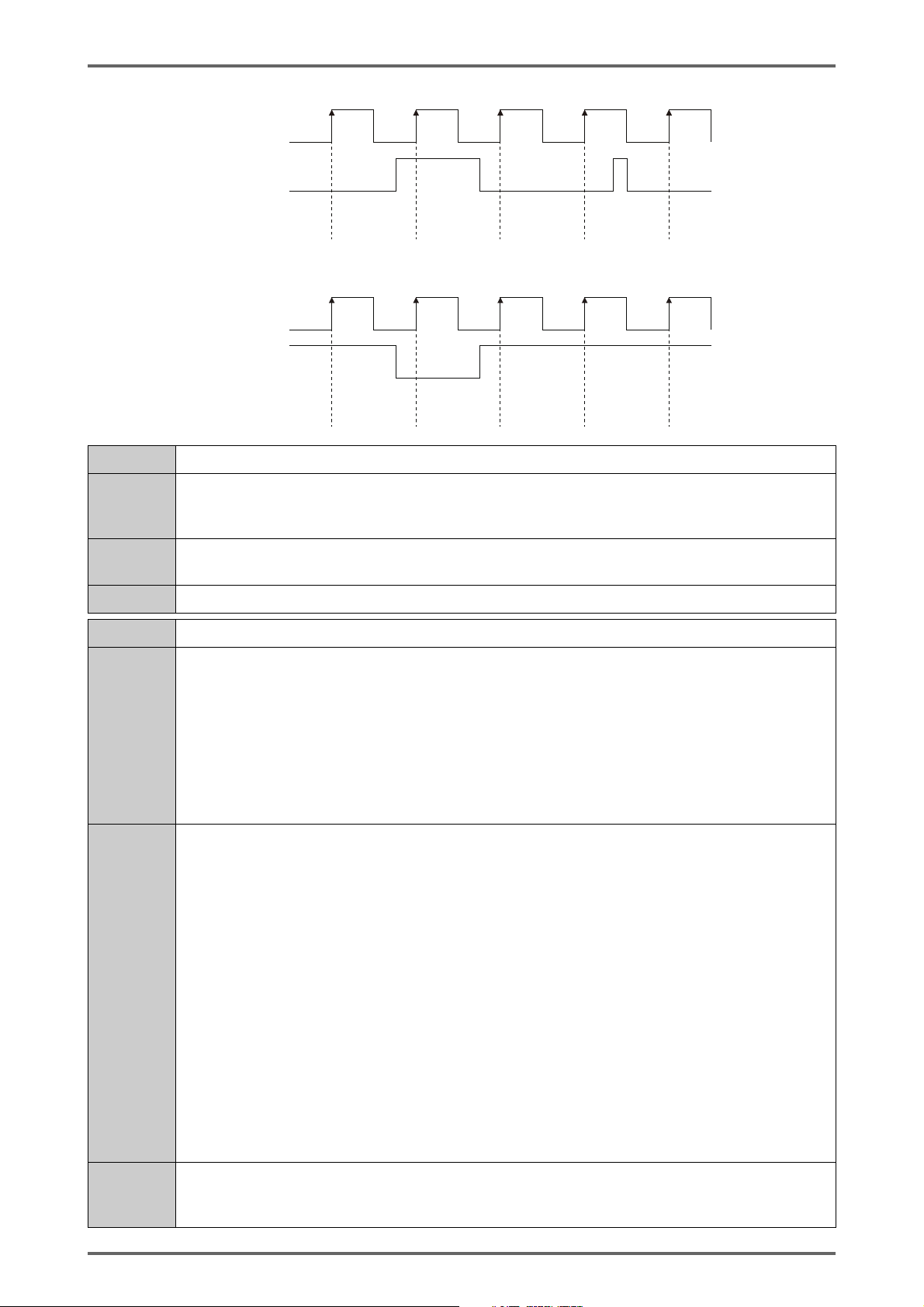
Example: Single phase 1x multiplier encoder trigger with no skipping
A phase ON
Z phase ON
Encoder count
Z-phase flag
Note: When the Z-phase input uses a negative logic encoder, set the TRG minimum input time, which is a common measurement
setting, to 7 μs. With negative logic, the Z-phase flag turns ON as shown in the following figure.
A phase ON
Z phase ON
Encoder count
Z-phase flag
OFF
OFF
OFF
OFF
1
OFF
1
OFF
2
ON
2
ON
3
ON
3
ON
4
OFF
4
OFF
5
ON
5
OFF
Name Profile footer information structure
Typedef struct {
Definition
DWORD reserve;
} LJV7IF_PROFILE_FOOTER;
Description
The footer information added to the profile.
None (reserved only).
Comment
-
Name High-speed mode get profile request structure (batch measurement: off)
Typedef struct {
BYTE byTargetBank;
BYTE byPosMode;
BYTE reserve[2];
Definition
DWORD dwGetProfNo;
BYTE byGetProfCnt;
BYTE byErase;
BYTE reserve[2];
} LJV7IF_GET_PROFILE_REQ;
The get profile designation information when the operation mode is "high-speed (profile only)"
and batch measurements are off in the get profile command.
byTargetBank
Specifies whether to get the profiles from the active surface or whether to get the profiles
from the inactive surface. See LJV7IF_PROFILE_BANK. (P.9)
byPosMode
Specifies the get profile position specification method. See LJV7IF_PROFILE_POS.
Description
dwGetProfNo
When byPosMode is LJV7IF_PROFILE_POS_SPEC, specifies the profile number for the
profile to get.
byGetProfCnt
The number of profiles to read.
byErase
Specifies whether or not to erase the profile data that was read and the profile data older
than that.
0: Do not erase, 1: erase
Comment
If the communication buffer is insufficient, the number of profiles specified by byGetProfCnt
may not be acquired. In this situation, the maximum number of profiles that can be acquired
is returned.
14 LJ-V7000_COM_RM_E
Page 15

Name High-speed mode get profile request structure (batch measurement: on)
Typedef struct {
BYTE byTargetBank;
BYTE byPosMode;
BYTE reserve[2];
Definition
Description
DWORD dwGetBatchNo;
DWORD dwGetProfNo;
BYTE byGetProfCnt;
BYTE byErase;
BYTE reserve[2];
} LJV7IF_GET_BATCH_PROFILE_REQ;
The get profile designation information when the operation mode is "high-speed (profile only)"
and batch measurements are on in the get profile command.
byTargetBank
Specifies whether to get the profiles from the active surface or whether to get the profiles
from the inactive surface. See LJV7IF_PROFILE_BANK. (P.9)
byPosMode
Specifies the get profile position specification method. See LJV7IF_BATCH_POS.
dwGetBatchNo
When byPosMode is LJV7IF_BATCH_POS_SPEC, specifies the batch number for the
profile to get.
dwGetProfNo
Specifies the profile number to start getting profiles from in the specified batch number.
byGetProfCnt
The number of profiles to read.
byErase
Specifies whether or not to erase the batch data that was read and the batch data older
than that.
0: Do not erase, 1: erase
Comment
If the communication buffer is insufficient, the number of profiles specified by byGetProfCnt
may not be acquired. In this situation, the maximum number of profiles that can be acquired
is returned.
15LJ-V7000_COM_RM_E
Page 16

Name Advanced mode get profile request structure (batch measurement: on)
Typedef struct {
BYTE byPosMode;
BYTE reserve[3];
Definition
Description
Comment
DWORD dwGetBatchNo;
DWORD dwGetProfNo;
BYTE byGetProfCnt;
BYTE reserve[3];
} LJV7IF_GET_BATCH_PROFILE_ADVANCE_REQ;
The get profile designation information when the operation mode is "advanced (with OUT
measurement)" and batch measurements are on in the get batch profile command.
byPosMode
Specifies the get profile position specification method. See LJV7IF_BATCH_POS.
dwGetBatchNo
When byPosMode is LJV7IF_BATCH_POS_SPEC, specifies the batch number for the
profiles to get.
dwGetProfNo
Specifies the profile number for the profiles to get.
byGetProfCnt
The number of profiles to read.
If the communication buffer is insufficient, the number of profiles specified by byGetProfCnt
may not be acquired. In this situation, the maximum number of profiles that can be acquired
is returned.
Name High-speed mode get profile response structure (batch measurement: off)
Typedef struct {
DWORD dwCurrentProfNo;
DWORD dwOldestProfNo;
Definition
Description
Comment
DWORD dwGetTopProfNo;
BYTE byGetProfCnt;
BYTE reserve[3];
} LJV7IF_GET_PROFILE_RSP;
The profile information returned for the get profiles command when the operation mode is
"high-speed (profile only)" and batch measurements are off.
dwCurrentProfNo
The profile number at the current point in time.
dwOldestProfNo
The profile number for the oldest profile held by the controller.
dwGetTopProfNo
The profile number for the oldest profile out of those that were read this time.
byGetProfCnt
The number of profiles that were read this time.
-
16 LJ-V7000_COM_RM_E
Page 17

Name High-speed mode get profile response structure (batch measurement: on)
Typedef struct {
DWORD dwCurrentBatchNo;
DWORD dwCurrentBatchProfCnt;
DWORD dwOldestBatchNo;
DWORD dwOldestBatchProfCnt;
Definition
Description
DWORD dwGetBatchNo;
DWORD dwGetBatchProfCnt;
DWORD dwGetBatchTopProfNo;
BYTE byGetProfCnt;
BYTE byCurrentBatchCommited;
BYTE reserve[2];
} LJV7IF_GET_BATCH_PROFILE_RSP;
The profile information returned for the get profiles command when the operation mode is
"high-speed (profile only)" and batch measurements are on.
dwCurrentBatchNo
The batch number at the current point in time.
dwCurrentBatchProfCnt
The number of profiles in the newest batch.
dwOldestBatchNo
The batch number for the oldest batch held by the controller.
dwOldestBatchProfCnt
The number of profiles in the oldest batch held by the controller.
dwGetBatchNo
The batch number that was read this time.
dwGetBatchProfCnt
The number of profiles in the batch that was read this time.
dwGetBatchTopProfNo
Indicates what number profile in the batch is the oldest profile out of the profiles that were
read this time.
byGetProfCnt
The number of profiles that were read this time.
byCurrentBatchCommited
Indicates if the batch measurements for the newest batch number has finished.
0: Not finished, 1: finished
Comment
-
17LJ-V7000_COM_RM_E
Page 18

Name Advanced mode get profile response structure (batch measurement: on)
Typedef struct {
DWORD dwGetBatchNo;
DWORD dwGetBatchProfCnt;
Definition
Description
DWORD dwGetBatchTopProfNo;
BYTE byGetProfCnt;
BYTE reserve[3];
} LJV7IF_GET_BATCH_PROFILE_ADVANCE_RSP;
The profile information returned for the get profiles command when the operation mode is
"advanced mode (with OUT measurement)" and batch measurements are on.
dwGetBatchNo
The batch number that was read this time.
dwGetBatchProfCnt
The number of profiles in the batch that was read this time.
dwGetBatchTopProfNo
Indicates what number profile in the batch is the oldest profile out of the
profiles that were read this time.
byReadProfCnt
The number of profiles that were read this time.
Comment
Name Get storage status request structure
Definition
Description
Comment
Name Get storage status response structure
Definition
-
Typedef struct {
DWORD dwReadArea;
}LJV7IF_GET_ STRAGE_STATUS_REQ;
Get target designation information in the get storage status command.
dwReadArea
The storage surface to read.
• When the memory allocation setting is "double buffer"
0: Active surface, 1: Surface A, 2: Surface B
• When the memory allocation setting is "entire area (overwrite)", fixed as 1
• When the memory allocation setting is "entire area (do not overwrite)"
0: Active surface, surface specification (1 to 999)
"Active surface" refers to the surface of the buffer that profile data is being written onto. For
further details, refer to "9.2.9.2 Internal memory".
Typedef struct {
DWORD dwSurfaceCnt;
DWORD dwActiveSurface;
} LJV7IF_GET_STRAGE_STATUS_RSP;
Description
Comment
The storage status information returned for the get storage status command.
dwSurfaceCnt
Storage surface count
dwActiveSurface
The active storage surface.
When the active program has storage off, 0.
For details about "Storage surface", refer to "9.2.9.2.2 For operation mode: advanced (with
OUT measurement)".
18 LJ-V7000_COM_RM_E
Page 19

Name Storage information structure
Typedef struct {
BYTE byStatus;
BYTE byProgramNo;
Definition
Description
BYTE byTarget;
BYTE reserve[5];
DWORD dwStorageCnt;
} LJV7IF_ STORAGE_INFO;
Information related to the storage status.
byStatus
Storage status.
0: Empty (Takes on this value when the target surface has not operated even once in a
program with storage on)
1: Storing (only the active storage surface can be 1)
2: Storage complete
byProgramNo
The program number for the relevant storage surface.
byTarget
Storage target.0: Data storage, 2: profile storage, 3: batch profile storage.
However, when batch measurements are on and profile compression (time axis) is on, 2:
profile storage is stored.
dwStorageCnt
Storage count (batch count when batch is on)
Comment
Name Get storage data request structure
Definition
Description
Comment
For details about "Storage surface", refer to "9.2.9.2.2 For operation mode: advanced (with
OUT measurement)".
Typedef struct {
BYTE reserve[4];
DWORD dwSurface;
DWORD dwStartNo;
DWORD dwDataCnt;
} LJV7IF_GET_STORAGE_REQ;
The get data designation information in the get data storage data command and the get
profile storage data command.
dwSurface
Storage surface to read.
dwStartNo
The data number to start reading.
dwDataCnt
The number of items to read.
For details about "Storage surface", refer to "9.2.9.2.2 For operation mode: advanced (with
OUT measurement)".
19LJ-V7000_COM_RM_E
Page 20

Name Get batch profile storage request structure
Typedef struct {
BYTE reserve[4];
DWORD dwSurface;
Definition
Description
DWORD dwGetBatchNo;
DWORD dwGetBatchTopProfNo;
BYTE byGetProfCnt;
BYTE reserved[3];
} LJV7IF_GET_BATCH_PROFILE_STORAGE_REQ;
Get data designation information in the get batch storage data command.
dwSurface
Storage surface to read.
dwGetBatchNo
Batch number to read.
dwGetBatchTopProfNo
Specifies from what profile number in the batch to get the data.
byGetProfCnt
The number of profiles to read.
Comment
Name Get storage data response structure
Definition
Description
Comment
For details about "Storage surface", refer to "9.2.9.2.2 For operation mode: advanced (with
OUT measurement)".
Typedef struct {
DWORD dwStartNo;
DWORD dwDataCnt;
LJV7IF_TIME stBaseTime;
} LJV7IF_GET_STORAGE_RSP;
The get data information returned for the get storage data command and the get profile
storage command.
dwStartNo
The data number to start reading.
dwDataCnt
The number of items to read.
stBaseTime
Base time.
For details about base time, refer to "9.2.9.10 Time data added to storage data".
20 LJ-V7000_COM_RM_E
Page 21

Name Get batch profile storage response structure
Typedef struct {
DWORD dwGetBatchNo;
DWORD dwGetBatchProfCnt;
Definition
Description
DWORD dwGetBatchTopProfNo;
BYTE byGetProfCnt;
BYTE reserve[3];
LJV7IF_TIME stBaseTime;
} LJV7IF_GET_BATCH_PROFILE_STORAGE_RSP;
The get data information returned for the get batch profile storage command.
dwGetBatchNo
The batch number that was read this time.
dwGetBatchProfCnt
The number of profiles in the batch that was read this time.
dwGetBatchTopProfNo
Indicates what number profile in the batch is the oldest profile out of the profiles that were
read this time.
byGetProfCnt
The number of profiles that were read this time.
stBaseTime
Base time.
Comment
Name High-speed communication prep start request structure
Definition
Description
Comment
-
Typedef struct {
BYTE bySendPos;
BYTE reserve[3];
} LJV7IF_HIGH_SPEED_PRE_START_REQ;
High-speed communication start preparation request command
bySendPos
Send start position. 0: From previous send complete position (from oldest data if 1st time),
1: From oldest data (reacquire), 2: From next data
-
21LJ-V7000_COM_RM_E
Page 22

8.3 Callback function interface definition
void (*pCallBack)(
Format
Parameters
BYTE* pBuffer, DWORD dwSize, DWORD dwCount, DWORD dwNotify, DWORD
dwUser);
pBuffer(in)
A pointer to the buffer that stores the profile data.
The profile data is stored in this buffer with "LJV7IF_PROFILE_HEADER - signed 32-bit
profile data - LJV7IF_PROFILE_FOOTER" as a single unit of profile data, and only the
number of profiles that could be acquired (dwCount) are returned.
dwSize(in)
The size in BYTEs per single unit of the profile "LJV7IF_PROFILE_HEADER - signed 32bit profile data - LJV7IF_PROFILE_FOOTER" contained in pBuffer.
dwCount(in)
The number of profiles stored in pBuffer.
dwNotify(in)
Notification of an interruption in high-speed communication or a break in batch
measurements.
For details, see "8.3.1 Supplement".
dwUser(in)
User information set when high-speed communication was initialized.
Return
value
Explanation
None
When using the high-speed communication function, this callback function is called when
data is received and when there is a change in the communication state.
This callback function is called from a thread other than the main thread.
Take care to only implement storing profile data in a thread save buffer in the callback
function. As the thread used to call the callback function is the same as the thread used to
receive data, the processing time of the callback function affects the speed at which data
is received, and may stop communication from being performed properly in some
environments. Refer to the sample program for details.
Profile data is stored in 0.01 μm units.
22 LJ-V7000_COM_RM_E
Page 23
8.3.1 Supplement
8.3.1.1 dwNotify parameter
This section describes the dwNotify parameter used in the callback function.
In high-speed communication, the callback function is called when any number of events occur, in
addition to when profile data is received. These events can be checked with the dwNotify
parameter.
dwNotify = 0: Indicates that profile data is being communicated correctly. Refer to the table below
for values other than 0.
: May be returned.
: Will not be returned.
Batch
off
Batch
on
LSB 0 Continuous send was stopped (stop by command)
1
Continuous send was stopped (automatic stop)
2
Continuous send was stopped (automatic stop)
*1
*2
3 Reserved
4 Reserved
5 Reserved
6 Reserved
7 Reserved
8 Send interrupted by clear memory
9 Reserved
10 Reserved
11 Reserved
12 Reserved
13 Reserved
14 Reserved
15 Reserved
16
Finished sending the batch measurement amount of data
*3
17 Reserved
18 Reserved
19 Reserved
20 Reserved
21 Reserved
22 Reserved
23 Reserved
24 Reserved
25 Reserved
26 Reserved
27 Reserved
28 Reserved
29 Reserved
30 Reserved
MSB 31 Reserved
*1 The setting was modified
*2 The program was switched
*3 However, when REMOTE OFF/LASER OFF is turned ON, profiles up to the one currently
being sent are forwarded, so some of the batch measurement data may not be forwarded.
23LJ-V7000_COM_RM_E
Page 24

Bit 0 to 2 and bit 8 indicate that continuous send was stopped.
To restart continuous send, start the high-speed data communication in the following order:
"Finalize high-speed data communication" "Disconnect ethernet communication" "Start
ethernet communication" "Initialize ethernet high-speed communication" "Request preparation
for Ethernet high-speed data communication".
Bit 16 is only valid when batch measurements are on.
When batch measurements are on, the batch measurements can be ended even when the
configured batch count is not fulfilled. Therefore, the callback function is notified with this bit on in
order to determine the break in batch data.
24 LJ-V7000_COM_RM_E
Page 25
9 Functions
9.1 Function list
9.1.1 Operations for the DLL
These functions are processed normally even when the controller is in the system error state.
Function name Overview
LJV7IF_Initialize Initializes the DLL
LJV7IF_Finalize Performs the termination processing for the DLL
LJV7IF_GetVersion Gets the DLL version
9.1.2 Establish/disconnect the communication path with the controller
These functions are processed normally even when the controller is in the system error state.
Function name Overview
LJV7IF_UsbOpen Establishes a USB connection
LJV7IF_EthernetOpen Establishes an Ethernet connection
LJV7IF_CommClose
Disconnects the connection (both USB and
Ethernet)
9.1.3 System control
Excluding LJV7IF_RetrunToFactorySetting, these functions are processed normally even when the controller
is in the system error state. LJV7IF_RetrunToFactorySetting may fail in the system error state (when a head is
not connected, etc.).
Function name Overview
LJV7IF_RebootController Reboots the controller
LJV7IF_RetrunToFactorySetting Returns the controller to the factory settings
LJV7IF_GetError Gets the controller system error information
LJV7IF_ClearError Clears the controller system error
9.1.4 Measurement control
Processing for these functions fails when the controller is in the system error state.
Function name Overview
LJV7IF_Trigger Issues a trigger
LJV7IF_StartMeasure Starts measurements
LJV7IF_StopMeasure Stops measurements
LJV7IF_AutoZero Issues auto zero
LJV7IF_Timing Issues timing
LJV7IF_Reset Issues a reset
LJV7IF_ClearMemory Clears the internal memory
25LJ-V7000_COM_RM_E
Page 26

9.1.5 Functions related to modifying or reading settings
Processing for these functions fails when the controller is in the system error state.
Function name Overview
LJV7IF_SetSetting Sends a setting to the controller
LJV7IF_GetSetting Gets a setting from the controller
LJV7IF_InitializeSetting Initializes a controller setting
LJV7IF_ReflectSetting
LJV7IF_RewriteTemporarySetting
LJV7IF_CheckMemoryAccess
LJV7IF_SetTime Sets the date/time for the controller
LJV7IF_GetTime Gets the date/time for the controller
LJV7IF_ChangeActiveProgram Changes the active program number
LJV7IF_GetActiveProgram Gets the active program number
Reflects the contents of the write settings area in
the running settings area and the save area
Overwrites the contents of the write settings area
with the settings in the running settings area and
the save area
Checks whether or not settings are being saved to
the save area
9.1.6 Acquiring measurement results
Processing for these functions fails when the controller is in the system error state.
Function name Overview
LJV7IF_GetMeasurementValue Gets measurement values
LJV7IF_GetProfile
Gets profiles when the operation mode is "highspeed (profile only)"
LJV7IF_GetBatchProfile
LJV7IF_GetProfileAdvance
LJV7IF_GetBatchProfileAdvance
Gets profiles when the operation mode is "highspeed (profile only)"
* Use LJV7IF_GetProfile when Compression (time
axis) is on.
Gets profiles when the operation mode is
"advanced (with OUT measurement)"
Gets profiles when the operation mode is
"advanced (with OUT measurement)"
* Use LJV7IF_GetProfileAdvance when
Compression (time axis) is on.
26 LJ-V7000_COM_RM_E
Page 27
9.1.7 Storage function related
Processing for these functions fails when the controller is in the system error state.
Function name Overview
LJV7IF_StartStorage Starts storage
LJV7IF_StopStorage Stops storage
LJV7IF_GetStorageStatus Gets the storage status
LJV7IF_GetStorageData
LJV7IF_GetStorageProfile
LJV7IF_GetStorageBatchProfile
Gets the stored data when the storage target is
"OUT value"
Gets the stored profiles when the storage target is
"Profiles"
Gets the stored profiles when the storage target is
"Profiles"
* Use LJV7IF_GetStorageProfile when
Compression (time axis) is on.
9.1.8 High-speed data communication related
Processing for these functions fails when the controller is in the system error state.
Function name Overview
LJV7IF_HighSpeedDataUSBCommunicationInitalize
LJV7IF_HighSpeedDataEthernetCommunicationInitalize
LJV7IF_PreStartHighSpeedDataCommunication
LJV7IF_StartHighSpeedDataCommunication Starts high-speed data communication
Performs the initialization required for
high-speed data communication (USB)
Performs the initialization required for
high-speed data communication
(Ethernet)
Requests preparation before starting
high-speed data communication
LJV7IF_StopHighSpeedDataCommunication Stops high-speed data communication
LJV7IF_HighSpeedDataCommunicationFinalize
Performs high-speed data
communication termination processing
27LJ-V7000_COM_RM_E
Page 28
9.2 Function reference
The type of the return value for the functions where there is a possibility of an error occurring is LONG.
Normally, 0 (ERR_NONE) is returned, and the return code is expressed in the lower 2 bytes (the upper 2
bytes are reserved).
For the common return codes for functions, see "10 Common Return Codes". For the individual return codes
for functions, see the function description in this chapter. The return codes are listed as the lower 2 bytes in
hexadecimal (example: 0x0100).
9.2.1 Operations for the DLL
Initialize DLL
Format LONG LJV7IF_Initialize(void);
Parameters -
Return value No individual return code
Explanation This function initializes the DLL. (Always run this function)
Supported version 1.00
Finalize DLL
Format LONG LJV7IF_Finalize(void);
Parameters -
Return value No individual return code
Explanation
Supported version 1.00
This function performs the termination processing for the DLL. (Always run this
function)
Get DLL version
Format DWORD LJV7IF_GetVersion(void);
Parameters -
Return value DLL version
This function gets the DLL version.
The version is expressed as a hexadecimal number. Viewed as hexadecimal,
the 4th digit is the major version, the 3rd digit is the minor version, the 2nd digit
is the revision, and the 1st digit is the build. For example, the initial version
Explanation
(1.2.3.4) is expressed as 0x1234.
The major version is incremented when the DLL's backward compatibility is lost.
The minor revision is incremented when the version is updated with additional
functions.
Supported version 1.00
28 LJ-V7000_COM_RM_E
Page 29
9.2.2 Establish/disconnect the communication path with the controller
For communication devices, see "9.2.9.1 Communication devices".
USB communication connection
Format LONG LJV7IF_UsbOpen(LONG lDeviceId);
Parameters
Return value No individual return code
Explanation
Supported version 1.00
lDeviceId(in)
Specifies the communication device to communicate with.
This function establishes a connection with the controller so that the library can
communicate with a USB-connected controller.
Ethernet communication connection
Format
Parameters
Return value No individual return code
Explanation
Supported version 1.00
LONG LJV7IF_EthernetOpen
(LONG lDeviceId, LJV7IF_ETHERNET_CONFIG* pEthernetConfig);
lDeviceId(in)
Specifies the communication device to communicate with.
pEthernetConfig(in)
Ethernet communication settings.
For each member, see "8 Constant, Structure Definitions"
This function establishes a connection with the controller so that the library can
communicate with an Ethernet-connected controller.
Disconnect communication path
Format LONG LJV7IF_CommClose(LONG lDeviceId);
Parameters
Return value No individual return code
Explanation
Supported version 1.00
lDeviceId(in)
Specifies the communication device to communicate with.
This function closes the USB or Ethernet connection.
Even if this function is called when a connection has not been established, an
error does not occur.
9.2.3 System control
For communication devices, see "9.2.9.1 Communication devices".
Reboot the controller
Format LONG LJV7IF_RebootController(LONG lDeviceId);
Parameters
Return value 0x80A0: Accessing the save area
Explanation
lDeviceId(in)
Specifies the communication device to communicate with.
This function reboots the controller and connected devices.
An error occurs while accessing the save area.
Supported version 1.00
29LJ-V7000_COM_RM_E
Page 30

Return to factory state
Format LONG LJV7IF_RetrunToFactorySetting(LONG lDeviceId);
Parameters
Return value No individual return code
Explanation
Supported version 1.00
lDeviceId(in)
Specifies the communication device to communicate with.
This function returns all of the controller's settings to the factory state.
After processing returns from this interface, write processing is being performed
to the save area in the controller.
Before turning off the power, ensure that you check the access status to the save
area with the LJV7IF_CheckMemoryAccess function (see "9.1.5 Functions
related to modifying or reading settings").
Get system error information
Format
Parameters
LONG LJV7IF_GetError
(LONG lDeviceId, BYTE byRcvMax, BYTE* pbyErrCnt, WORD* pwErrCode);
lDeviceId(in)
Specifies the communication device to communicate with.
byRcvMax(in)
Specifies the maximum amount of system error information to receive.
(Size of the buffer passed in pwErrCode)
pbyErrCnt(out)
The buffer to receive the amount of system error information.
pwErrCode(out)
The buffer to receive the system error information. In order from the newest
error, *pbyErrCnt items (byRcvMax items max) worth of system error
information is stored.
Return value No individual return code
This function gets the controller's system error information.
Explanation
Supported version 1.00
For the details of the meanings of the error codes that are returned, refer to the
"LJ-V7000 Series User's Manual".
Clear system error
Format LONG LJV7IF_ClearError(LONG lDeviceId, WORD wErrCode);
lDeviceId(in)
Parameters
Return value No individual return code
Explanation
Specifies the communication device to communicate with.
wErrCode(in)
The error code for the error you wish to clear.
This function clears the system error occurring on the controller.
When all of the system errors that are occurring are successfully cleared, the
controller will start measurements.
Only the errors listed below can be cleared.
0x0084: Two heads were connected when previously started, but only one head
could be recognized
0x0085: The connected head type is different than when previously started
Supported version 1.00
30 LJ-V7000_COM_RM_E
Page 31

9.2.4 Measurement control
For communication devices, see "9.2.9.1 Communication devices".
Trigg er
Format LONG LJV7IF_Trigger(LONG lDeviceId);
Parameters
Return value 0x8080: The trigger mode is not "external trigger"
Explanation This function issues a trigger.
Supported version 1.00
lDeviceId(in)
Specifies the communication device to communicate with.
Start batch measurements
Format LONG LJV7IF_StartMeasure(LONG lDeviceId);
Parameters
Return value
Explanation
Supported version 1.00
lDeviceId(in)
Specifies the communication device to communicate with.
0x8080: Batch measurements are off
0x80A0: Batch measurement start processing could not be performed
because the REMOTE terminal is off or the LASER_OFF terminal is
on
This function starts batch measurements. When batch measurements have
already been started, nothing happens and there is no error.
Stop batch measurements
Format LONG LJV7IF_StopMeasure(LONG lDeviceId);
Parameters
Return value
Explanation
Supported version 1.00
lDeviceId(in)
Specifies the communication device to communicate with.
0x8080: Batch measurements are off
0x80A0: Batch measurement stop processing could not be performed
because the REMOTE terminal is off or the LASER_OFF terminal is
on
This function stops batch measurements. When batch measurements have not
been started, nothing happens and there is no error.
31LJ-V7000_COM_RM_E
Page 32

Auto zero
Format LONG LJV7IF_AutoZero(LONG lDeviceId, BYTE byOnOff, DWORD dwOut);
lDeviceId(in)
Specifies the communication device to communicate with.
byOnOff(in)
Other than 0: Auto zero on request, 0: off request.
Parameters
Return value 0x8080: The operation mode is "high-speed (profile only)"
Explanation
Supported version 1.00
dwOut(in)
Specifies the OUT to target for processing as a bit.
From the LSB, OUT1, OUT2, to OUT16 are indicated by bits, and the OUT is
the target for processing when the bit is 1 (upper 16 bits are reserved).
Example: When you wish to set OUT1 and OUT5 to be the targets for
processing
Specify dwOut = 0x00000011 (... 0000 0000 0001 0001).
This function issues an auto zero request.
Even when the OUT targeted for processing is configured to not be measured,
an error will not occur.
Timing
Format LONG LJV7IF_Timing(LONG lDeviceId, BYTE byOnOff, DWORD dwOut);
lDeviceId(in)
Specifies the communication device to communicate with.
Parameters
Return value 0x8080: The operation mode is "high-speed (profile only)"
Explanation
Supported version 1.00
byOnOff(in)
Same specification method as auto zero (LJV7IF_AutoZero).
dwOut(in)
Same specification method as auto zero (LJV7IF_AutoZero).
This function issues a timing request.
Even when the OUT targeted for processing is configured to not be measured,
an error will not occur.
Reset
Format LONG LJV7IF_Reset(LONG lDeviceId, DWORD dwOut);
lDeviceId(in)
Parameters
Specifies the communication device to communicate with.
dwOut(in)
Same specification method as auto zero (LJV7IF_AutoZero).
Return value 0x8080: The operation mode is "high-speed (profile only)"
This function issues a reset request.
Explanation
Supported version 1.00
Even when the OUT targeted for processing is configured to not be measured,
an error will not occur.
32 LJ-V7000_COM_RM_E
Page 33

Clear memory
Format LONG LJV7IF_ClearMemory(LONG lDeviceId);
Parameters
Return value No individual return code
Explanation
Supported version 1.00
lDeviceId(in)
Specifies the communication device to communicate with.
When the operation mode is "high-speed (profile only)", this function clears the
profile data accumulated in internal memory.
When the operation mode is "advanced (with OUT measurement)", the
accumulated storage data is cleared.
9.2.5 Functions related to modifying or reading settings
For communication devices, see "9.2.9.1 Communication devices".
Send setting
LONG LJV7IF_SetSetting(LONG lDeviceId, BYTE byDepth,
Format
Parameters
LJV7IF_TARGET_SETTING TargetSetting, void* pData, DWORD dwDataSize,
DWORD* pdwError);
lDeviceId(in)
Indicates the communication device to communicate with.
byDepth(in)
Specifies the level to reflect the setting value to that was sent.
(LJV7IF_SETTING_DEPTH)
TargetSetting(in)
Identifies the item that is the target to send.
pData(in)
Specifies the buffer that stores the setting data to send.
dwDataSize(in)
The size in BYTEs of the setting data to send.
pdwError(out)
The buffer for receiving detailed setting errors (see "9.2.9.4 Detailed setting
errors").
* For details on the parameters, see the appendix.
Return value No individual return code
This function sends the setting for the specified item to the controller.
Explanation
Supported version 1.00
For the procedure to reflect the setting on the controller, see "9.2.9.3 Write
processing for settings".
33LJ-V7000_COM_RM_E
Page 34

Get setting
Format
Parameters
Return value No individual return code
Explanation This function gets the setting for the specified item from the controller.
Supported version 1.00
LONG LJV7IF_GetSetting(LONG lDeviceId, BYTE byDepth,
LJV7IF_TARGET_SETTING TargetSetting, void* pData, DWORD dwDataSize);
lDeviceId(in)
Specifies the communication device to communicate with.
byDepth(in)
Specifies the level of the setting value to get. (LJV7IF_SETTING_DEPTH)
TargetSetting(in)
Identifies the item that is the target to get.
pData(out)
Specifies the buffer to receive the setting data that was acquired.
dwDataSize(in)
The size of the buffer to receive the acquired data in BYTEs.
* For details on the parameters, see the appendix.
Initialize setting
Format
LONG LJV7IF_InitializeSetting(LONG lDeviceId, BYTE byDepth, BYTE
byTarget);
lDeviceId(in)
Specifies the communication device to communicate with.
byDepth(in)
Parameters
Return value No individual return code
Explanation
Supported version 1.00
Specifies the level to reflect the initialized setting. (LJV7IF_SETTING_DEPTH)
byTarget (in)
Specifies the setting that is the target for initialization.
(LJV7IF_INIT_SETTING_TARGET)
This function initializes the setting specified as the initialization target.
For the procedure to reflect the setting on the controller, see "9.2.9.3 Write
processing for settings".
34 LJ-V7000_COM_RM_E
Page 35

Request to reflect settings in the write settings area
Format
Parameters
Return value No individual return code
Explanation
Supported version 1.00
LONG LJV7IF_ReflectSetting(LONG lDeviceId, BYTE byDepth,
DWORD*pdwError);
lDeviceId(in)
Specifies the communication device to communicate with.
byDepth (in)
Specifies to what level the settings written in the write settings area will be
reflected to. (LJV7IF_SETTING_DEPTH)
pdwError(out)
The buffer for receiving detailed setting errors (see "9.2.9.4 Detailed setting
errors").
This function reflects the settings stored in the write settings area to the running
settings area.
When LJV7IF_SETTING_DEPTH_SAVE is specified as a parameter, the settings
in the save area can be saved.
When the controller was instructed to overwrite the settings in the save area with
this function, ensure that you check the access status to the save area with the
LJV7IF_CheckMemoryAccess function before turning the power off.
Update write settings area
Format LONG LJV7IF_RewriteTemporarySetting(LONG lDeviceId, BYTE byDepth);
lDeviceId(in)
Specifies the communication device to communicate with.
Parameters
Return value No individual return code
Explanation
Supported version 1.00
byDepth (in)
Specifies the level of the settings to update the write settings area with.
(LJV7IF_SETTING_DEPTH)
This function updates the contents of the write settings area with either the
settings in the running settings area or the settings saved in the save area.
Check the status of saving to the save area
Format LONG LJV7IF_CheckMemoryAccess(LONG lDeviceId, BYTE* pbyBusy);
lDeviceId(in)
Specifies the communication device to communicate with.
Parameters
Return value No individual return code
pbyBusy(out)
The buffer for receiving information on whether the save area is being
accessed
Other than 0: Accessing the save area, 0: no access.
This function checks whether or not the controller is accessing the save area
with an operation such as that to save settings.
When the controller was instructed to save settings to the save area with the
Explanation
Supported version 1.00
LJV7IF_RetrunToFactorySetting function (see "9.1.3 System control"), the
LJV7IF_SetSetting function, the LJV7IF_InitializeSetting function, or the
LJV7IF_ReflectSetting function, check that access to the save area has
completed with this function before turning off the power.
35LJ-V7000_COM_RM_E
Page 36

Set date/time
Format LONG LJV7IF_SetTime(LONG lDeviceId, LJV7IF_TIME* pTime);
lDeviceId(in)
Specifies the communication device to communicate with.
Parameters
Return value No individual return code
Explanation This function sets the date/time for the controller.
Supported version 1.00
pTime(in)
The date/time to set.
For each member, see "8 Constant, Structure Definitions".
Get date/time
Format LONG LJV7IF_GetTime(LONG lDeviceId, LJV7IF_TIME* pTime);
lDeviceId(in)
Specifies the communication device to communicate with.
Parameters
Return value No individual return code
pTime(out)
The buffer to store the acquired date/time.
For each member, see "8 Constant, Structure Definitions".
Explanation This function gets the date/time from the controller.
Supported version 1.00
Change program
Format LONG LJV7IF_ChangeActiveProgram(LONG lDeviceId, BYTE byProgNo);
lDeviceId(in)
Specifies the communication device to communicate with.
Parameters
Return value 0x8080: The change program setting is "terminal"
Explanation
Supported version 1.00
byProgNo(in)
Program number after the change.
Specify as 0 to 15 (0: Program 0, 1: Program 1, and so on).
This function changes the active program number.
When specifying the same number as the active program number in byProgNo,
or when an invalid program number is specified, the operation to change the
program is performed (internal memory is cleared, etc.), but the active program
number is not changed.
Get the active program number
Format LONG LJV7IF_GetActiveProgram(LONG lDeviceId, BYTE* pbyProgNo);
lDeviceId(in)
Specifies the communication device to communicate with.
Parameters
Return value No individual return code
Explanation This function gets the active program number.
Supported version 1.00
pbyProgNo(out)
The buffer to receive the active program number.
It is stored as 0 to 15 (0: Program 0, 1: Program 1, and so on).
36 LJ-V7000_COM_RM_E
Page 37

9.2.6 Acquiring measurement results
For communication devices, see "9.2.9.1 Communication devices".
Get measurement results
Format
Parameters
Return value 0x8080: The operation mode is "high-speed (profile only)"
Explanation
Supported version 1.00
Get profiles (operation mode "high-speed (profile only)")
Format
LONG LJV7IF_GetMeasurementValue(LONG lDeviceId,
LJV7IF_MEASURE_DATA* pMeasureData);
lDeviceId(in)
Specifies the communication device to communicate with.
pMeasureData(out)
This buffer stores the data for all 16 OUTs including the OUTs that are not
measuring.
The host requires the passing of a buffer LJV7IF_MEASURE_DATA[16] in
size.
This function gets the newest measurement results (measurement values and
judgment results). All measurements, including OUT measurements where the
measurement mode is set to "do not measure" are acquired.
LONG LJV7IF_GetProfile(LONG lDeviceId, LJV7IF_GET_PROFILE_REQ* pReq,
LJV7IF_GET_PROFILE_RSP* pRsp, LJV7IF_PROFILE_INFO* pProfileInfo,
DWORD* pdwProfileData, DWORD dwDataSize);
Parameters
Return value
Explanation
lDeviceId(in)
Specifies the communication device to communicate with.
pReq(in)
Specifies the position, etc., of the profiles to get.
For each member, see "8 Constant, Structure Definitions".
pRsp(out)
Indicates the position, etc., of the profiles that were actually acquired.
For each member, see "8 Constant, Structure Definitions".
pProfileInfo(out)
The profile information for the acquired profiles.
For each member, see "8 Constant, Structure Definitions".
pdwProfileData (out)
The buffer to get the profile data.
The profile data is stored in this buffer with "LJV7IF_PROFILE_HEADER signed 32-bit profile data - LJV7IF_PROFILE_FOOTER" as a single unit of
profile data, and only the number of profiles that could be acquired are
returned.
dwDataSize(in)
pdwProfileData size in BYTEs
0x8080: The operation mode is "advanced (with OUT measurement)"
0x8081: "Batch measurements on and profile compression (time axis) off"
0x80A0: No profile data
This function gets profile data.
Profile data is stored in 0.01 μm units.
For the details on the data stored in the profile data (storage order and size), see
"9.2.9 Supplement".
There is a limit to the number of profiles that can be read at once. This limit
depends on the measurement settings. Refer to byGetProfCnt (the number of
profiles read this time) in pRsp, and confirm that the data you wish to acquire
has all been acquired. If it could not be acquired, specify the following in this
function to acquire the remaining data:
byPosMode in pReq = LJV7IF_PROFILE_POS_SPEC
dwGetProfNo in pReq = dwGetTopProfNo in pRsp + byGetProfCnt in pRsp
(Specify the profile data to be read as the next profile data after the profile data
that was read this time)
Supported version 1.00
37LJ-V7000_COM_RM_E
Page 38

Get batch profiles (operation mode "high-speed (profile only)")
LONG LJV7IF_GetBatchProfile(LONG lDeviceId,
Format
Parameters
LJV7IF_GET_BATCH_PROFILE_REQ* pReq,
LJV7IF_GET_BATCH_PROFILE_RSP* pRsp, LJV7IF_PROFILE_INFO *
pProfileInfo, DWORD* pdwBatchData, DWORD dwDataSize);
lDeviceId(in)
Specifies the communication device to communicate with.
pReq(in)
Specifies the position, etc., of the profiles to get.
For each member, see "8 Constant, Structure Definitions".
pRsp(out)
Indicates the position, etc., of the profiles that were actually acquired.
For each member, see "8 Constant, Structure Definitions".
pProfileInfo(out)
The profile information for the acquired profiles.
For each member, see "8 Constant, Structure Definitions".
pdwBatchData(out)
The buffer to get the profile data.
The profile data is stored in this buffer with "LJV7IF_PROFILE_HEADER signed 32-bit profile data - LJV7IF_PROFILE_FOOTER" as a single unit of
profile data, and only the number of profiles that could be acquired are
returned.
dwDataSize(in)
pdwProfileData size in BYTEs
0x8080: The operation mode is "advanced (with OUT measurement)"
Return value
Explanation
Supported version 1.00
0x8081: Not "batch measurements on and profile compression (time axis) off"
0x80A0: No batch data (batch measurements not run even once)
This function gets profile data.
Profile data is stored in 0.01 μm units.
For the details on the data stored in the profile data (storage order and size), see
"9.2.9 Supplement".
To read all of the profiles in one batch, read them with the procedure below.
1. Call this function by specifying LJV7IF_BATCH_POS_CURRENT for
2. Configure pReq as listed below and call this function again.
3. Update dwGetProfNo in step 2 and call this function until all of the profiles in
byPosMode in pReq. Save the start position and the amount of profiles that
were read and the batch number that was read.
byPosMode = LJV7IF_BATCH_POS_SPEC
dwGetBatchNo = batch number that was read
byGetProfNo = starting profile number of the unread profiles in the batch
the batch can be read.
38 LJ-V7000_COM_RM_E
Page 39

Get profiles (operation mode "advanced (with OUT measurement)")
LONG LJV7IF_GetProfileAdvance(LONG lDeviceId, LJV7IF_PROFILE_INFO*
Format
Parameters
Return value
pProfileInfo, DWORD* pdwProfileData, DWORD dwDataSize,
LJV7IF_MEASURE_DATA* pMeasureData);
lDeviceId(in)
Specifies the communication device to communicate with.
pProfileInfo(out)
The profile information for the acquired profiles.
For each member, see "8 Constant, Structure Definitions".
pdwProfileData (out)
The buffer to get the profile data.
In the "LJV7IF_PROFILE_HEADER - signed 32-bit profile data LJV7IF_PROFILE_FOOTER" format, one item of profile data is stored.
dwDataSize(in)
pdwProfileData size in BYTEs
pMeasureData(out)
This buffer stores the data for all 16 OUTs including the OUTs that are not
measuring.
The host requires the passing of a buffer LJV7IF_MEASURE_DATA[16] in
size.
0x8080: The operation mode is "high-speed (profile only)"
0x8081: "Batch measurements on and profile compression (time axis) off"
0x80A0: No profile data
This function gets profile data.
Profile data is stored in 0.01 μm units.
Explanation
Supported version 1.00
For the details on the data stored in the profile data (storage order and size), see
"9.2.9 Supplement". For pMeasureData, OUT measurements where the
measurement mode is set to "do not measure" are also stored.
39LJ-V7000_COM_RM_E
Page 40

Get batch profiles (operation mode "advanced (with OUT measurement)")
LONG LJV7IF_GetBatchProfileAdvance(LONG lDeviceId,
LJV7IF_GET_BATCH_PROFILE_ADVANCE_REQ* pReq,
Format
Parameters
LJV7IF_GET_BATCH_PROFILE_ADVANCE_RSP* pRsp,
LJV7IF_PROFILE_INFO* pProfileInfo, DWORD* pdwBatchData, DWORD
dwDataSize, LJV7IF_MEASURE_DATA* pBatchMeasureData,
LJV7IF_MEASURE_DATA* pMeasureData);
lDeviceId(in)
Specifies the communication device to communicate with.
pReq(in)
Specifies the position, etc., of the profiles to get.
For each member, see "8 Constant, Structure Definitions".
pRsp(out)
Indicates the position, etc., of the profiles that were actually acquired.
For each member, see "8 Constant, Structure Definitions"
pProfileInfo(out)
The profile information for the acquired profiles.
For each member, see "8 Constant, Structure Definitions".
dwBatchData(out)
The buffer to get the profile data.
The profile data is stored in this buffer with "LJV7IF_PROFILE_HEADER signed 32-bit profile data - LJV7IF_PROFILE_FOOTER LJV7IF_MEASURE_DATA x 16 OUTs" as a single unit of profile data, and only
the number of profiles that could be acquired are returned.
The results of the measurement process for the relevant profile are stored in
LJV7IF_MEASURE_DATA.
dwDataSize(in)
pdwProfileData size in BYTEs.
pBatchMeasureData(out)
The measurement results for the batch data that is the target to get.
This buffer stores the data for all 16 OUTs including the OUTs that are not
measuring.
pMeasureData(out)
The newest measurement results at the time the command was processed.
This buffer stores the data for all 16 OUTs including the OUTs that are not
measuring.
The host requires the passing of a buffer LJV7IF_MEASURE_DATA[16] in size.
0x8080: The operation mode is "high-speed (profile only)"
Return value
Explanation
Supported version 1.00
0x8081: Not "batch measurements on and profile compression (time axis) off"
0x80A0: No batch data (batch measurements not run even once)
This function gets profile data.
Profile data is stored in 0.01 μm units.
For the details on the data stored in the profile data (storage order and size), see
"9.2.9 Supplement". For pdwBatchData/pBatchMeasureData, OUT
measurements where the measurement mode is set to "do not measure" are also
stored.
To read all of the profiles in one batch, read them with the procedure below.
When calling this function, do not perform communication between the target
controller and LJ-Navigation 2.
1. Call this function by specifying LJV7IF_BATCH_POS_CURRENT for
byPosMode in pReq. Save the start position and the amount of profiles
that were read and the batch number that was read.
2. Configure pReq as listed below and call this function again.
byPosMode=LJV7IF_BATCH_POS_SPEC
dwGetBatchNo = batch number that was read
dwGetProfNo = starting profile number of the unread profiles in the batch
3. Update dwGetProfNo in step 2 and call this function until all of the profiles
in the batch can be read.
40 LJ-V7000_COM_RM_E
Page 41

9.2.7 Store function related
For communication devices, see "9.2.9.1 Communication devices".
Start storage
Format LONG LJV7IF_StartStorage(LONG lDeviceId);
Parameters
Return value
Explanation
Supported version 1.00
lDeviceId(in)
Specifies the communication device to communicate with.
0x8080: The operation mode is "high-speed (profile only)"
0x8081: Storage target setting is "OFF" (no storage)
0x8082: The storage condition setting is not "terminal/command"
When the storage condition setting is terminal/command, this function requests
the start of storage.
Stop storage
Format LONG LJV7IF_StopStorage(LONG lDeviceId);
Parameters
Return value
Explanation
Supported version 1.00
lDeviceId(in)
Specifies the communication device to communicate with.
0x8080: The operation mode is "high-speed (profile only)"
0x8081: Storage target setting is "off" (no storage)
0x8082: The storage condition setting is not "terminal/command"
When the storage condition setting is terminal/command, this function requests
the stop (cancellation) of storage.
Get storage status
LONG LJV7IF_GetStorageStatus(LONG lDeviceId,
Format
Parameters
Return value 0x8080: The operation mode is "high-speed (profile only)"
Explanation When the storage target setting is not off, this function gets the storage status.
Supported version 1.00
LJV7IF_GET_STORAGE_STATUS_REQ* pReq,
LJV7IF_GET_STORAGE_STATUS_RSP* pRsp, LJV7IF_ STORAGE_INFO*
pStorageInfo);
lDeviceId(in)
Specifies the communication device to communicate with.
pReq(in)
Specifies the target of the storage status to get.
For each member, see "8 Constant, Structure Definitions".
pRsp(out)
Represents the actually acquired storage status.
For each member, see "8 Constant, Structure Definitions".
pStorageInfo(out)
Storage information destination. If dwActiveSurface in pRsp is 0, the storage
status is not updated
41LJ-V7000_COM_RM_E
Page 42

Get data storage data
LONG LJV7IF_GetStorageData(LONG lDeviceId, LJV7IF_GET_STORAGE_REQ*
Format
Parameters
pReq, LJV7IF_STORAGE_INFO* pStorageInfo, LJV7IF_GET_STORAGE_RSP*
pRsp, DWORD* pdwData, DWORD dwDataSize);
lDeviceId(in)
pReq(in)
pStorageInfo(out)
pRsp(out)
pdwData(out)
dwDataSize(in)
Specifies the communication device to communicate with.
Specifies the storage data to get.
For each member, see "8 Constant, Structure Definitions".
Represents the actually acquired storage information.
For each member, see "8 Constant, Structure Definitions".
Represents the position and size of the actually acquired storage data.
For each member, see "8 Constant, Structure Definitions".
The buffer to get the storage data.
The storage data is stored in this buffer with "counter value in 10 ms units
from the 32-bit base time - LJV7IF_MEASURE_DATA[16]" as a single unit of
storage data, and only the amount of storage data that could be acquired is
returned.
For each member, see "8 Constant, Structure Definitions". For details about
counter value in 10 ms units, refer to "9.2.9.10 Time data added to storage
data".
pdwData size in BYTEs
Return value
Explanation
Supported version 1.00
0x8080: The operation mode is "high-speed (profile only)"
0x8081: The storage target setting is not "OUT value"
When the storage target setting is "OUT value", this function gets the storage
data. Data can be acquired even if it is within the storage period. If there is no
accumulated data, 0 is returned for the number of items read in pRsp. If the data
specified by the data number to start reading in pRep has not been
accumulated, one piece of the newest data that has been accumulated is
returned. In pdwData, OUT measurements where the measurement mode is set
to "do not measure" are also stored. There is a limit to the amount of data that
can be read at once. This limit depends on the measurement settings. Refer to
dwDataCnt (the number of items read) in pRsp, and confirm that the data you
wish to acquire has all been acquired. If it could not be acquired, specify the
following in this function to acquire the remaining data:
dwStartNo in pReq = dwStartNo in pRsp + dwDataCnt (Specify the data to be
read as the next piece of data after the data that was read this time)
42 LJ-V7000_COM_RM_E
Page 43

Get profile storage data
LONG LJV7IF_GetStorageProfile(LONG lDeviceId,
Format
Parameters
LJV7IF_GET_STORAGE_REQ* pReq, LJV7IF_STORAGE_INFO* pStorageInfo,
LJV7IF_GET_STORAGE_RSP* pRsp, LJV7IF_PROFILE_INFO* pProfileInfo,
DWORD* pdwData, DWORD dwDataSize);
lDeviceId(in)
Specifies the communication device to communicate with.
pReq(in)
Specifies the profiles to get.
For each member, see "8 Constant, Structure Definitions".
pStorageInfo(out)
Represents the actually acquired storage information.
For each member, see "8 Constant, Structure Definitions".
pRsp(out)
Indicates the position and size of the profiles that were actually acquired.
For each member, see "8 Constant, Structure Definitions".
pProfileInfo(out)
Indicates the profile information that was actually acquired.
For each member, see "8 Constant, Structure Definitions".
pdwData(out)
The buffer to get the storage data.
The profile storage data is stored in this buffer with "counter value in 10 ms
units from the 32-bit base time - LJV7IF_MEASURE_DATA[16] LJV7IF_PROFILE_HEADER - signed 32-bit profile data LJV7IF_PROFILE_FOOTER - LJV7IF_MEASURE_DATA[16]" as a single unit of
profile storage data, and only the amount of profile storage data that could
be acquired is returned.
The first LJV7IF_MEASURE_DATA[16] stores the newest measurement
values at that time, the second stores the measurement values for that profile.
For each member, see "8 Constant, Structure Definitions". For details about
counter value in 10 ms units, refer to "9.2.9.10 Time data added to storage
data".
dwDataSize(in)
pdwData size in BYTEs
0x8080: The operation mode is "high-speed (profile only)"
Return value
Explanation
Supported version 1.00
0x8081: The storage target setting is not profile, or "batch measurements on
When the storage target setting is profile, this function gets the stored profile
data. (Batch setting: off) Data can be acquired even if it is within the storage
period.
For the details on the data stored in the profile data (storage order and size), see
"9.2.9 Supplement".
If there is no accumulated data, 0 is returned for the number of items read in
pRsp. If the data specified by the data number to start reading in pRep has not
been accumulated, one item of the newest data that has been accumulated is
returned.
In pdwData, OUT measurements where the measurement mode is set to "do not
measure" are also stored.
There is a limit to the amount of profile data that can be read at once. This limit
depends on the measurement settings. Refer to dwDataCnt (the number of
items read) in pRsp, and confirm that the profile data you wish to acquire has all
been acquired. If it could not be acquired, specify the following in this function
to acquire the remaining data:
dwStartNo in pReq = dwStartNo in pRsp + dwDataCnt in pRsp
(Specify the profile data to be read as the next profile data after the profile data
that was read this time)
and profile compression (time axis) off"
43LJ-V7000_COM_RM_E
Page 44

Get batch profile storage data
LONG LJV7IF_GetStorageBatchProfile (LONG lDeviceId,
LJV7IF_GET_BATCH_PROFILE_STORAGE_REQ* pReq, LJV7IF_STORAGE_INFO*
Format
Parameters
pStorageInfo, LJV7IF_GET_BATCH_PROFILE_STORAGE_RSP* pRsp,
LJV7IF_PROFILE_INFO* pProfileInfo, DWORD* pdwData,
DWORD* pdwTimeOffset, LJV7IF_MEASURE_DATA* pMeasureData);
lDeviceId(in)
Specifies the communication device to communicate with.
pReq(in)
Specifies the profiles to get.
For each member, see "8 Constant, Structure Definitions".
pStorageInfo(out)
Represents the actually acquired storage information.
For each member, see "8 Constant, Structure Definitions".
pRsp(out)
Indicates the position and size of the profiles that were actually acquired.
For each member, see "8 Constant, Structure Definitions".
pProfileInfo(out)
Indicates the profile information that was actually acquired.
For each member, see "8 Constant, Structure Definitions".
pdwData (out)
The buffer to get the storage data.
The storage data is stored in this buffer with "LJV7IF_PROFILE_HEADER signed 32-bit profile data - LJV7IF_PROFILE_FOOTER LJV7IF_MEASURE_DATA[16]" as a single unit of storage data, and only the
storage data that could be acquired is returned.
The measurement results for each profile are stored in
LJV7IF_MEASURE_DATA[16].
For each member, see "8 Constant, Structure Definitions".
dwDataSize(in)
pdwData size in BYTEs
pdwTimeOffset(out)
The buffer for receiving the counter value in 10 ms units from the 32 bit base time.
For details about counter value in 10 ms units, refer to "9.2.9.10 Time data
added to storage data".
pMeasureData(out)
The measurement results for the relevant batch data.
This buffer stores the data for all 16 OUTs including the OUTs that are not
measuring.
The host requires the passing of a buffer LJV7IF_MEASURE_DATA[16] in size.
·
DWORD dwDataSize,
0x8080: The operation mode is "high-speed (profile only)"
0x8081: The storage target setting is not profile, or not "batch measurements
Return value
0x80A0: The batch data specified by the batch number to read
When the storage target setting is profile, this function gets the stored profile
data. (Batch setting: on)
Data can be acquired even if it is within the storage period.
For the details on the data stored in the profile data (storage order and size), see
"9.2.9 Supplement"
If the data specified by the number of the profile in the batch to get in pRep has
not been accumulated, one item of the newest data that has been accumulated
is returned.
In pdwData/pMeasureData, OUT measurements where the measurement mode
Explanation
Supported version 1.00
is set to "do not measure" are also stored.
Use the following procedure to read all profiles in a batch.
1. Call this function by specifying 0 for dwGetBatchTopProfNo in pReq. Save the
start position and the number of profiles that were read and the batch number
that was read.
2. Configure pReq as listed below and call this function again.
dwGetBatchNo = batch number that was read
dwGetBatchTopProfNo = first profile number of the unread profiles in the batch
3. Update by dwGetBatchTopProfNo in step 2 and call this function until all of
the profiles in the batch can be read.
on and profile compression (time axis) off"
(dwGetBatchNo) in pReq has not been accumulated yet
44 LJ-V7000_COM_RM_E
Page 45

9.2.8 High-speed data communication related
For communication devices, see "9.2.9.1 Communication devices".
Initialize USB high-speed data communication
LONG LJV7IF_HighSpeedDataUsbCommunicationInitalize (LONG lDeviceId,
Format
Parameters
Return value No individual return code
Explanation
void (*pCallBack)(BYTE*, DWORD, DWORD, DWORD, DWORD), DWORD
dwProfileCnt, DWORD dwThreadId);
lDeviceId(in)
Specifies the communication device to communicate with.
pCallBack(in)
Specifies the callback function to call when data is received by high-speed
communication.
dwProfileCnt(in)
Specifies the frequency to call the callback function. The callback function is
called when the specified number of profiles is received.
dwThreadId(in) (synonymous with dwUser)
Thread ID.
This function initializes high-speed communication for a USB connected
controller. It is necessary to maintain a unique communication path (not used for
normal command communication) for high-speed communication. This function
establishes a unique high-speed communication path.
Supported version 1.00
Initialize Ethernet high-speed data communication
LONG LJV7IF_HighSpeedDataEthernetCommunicationInitalize (LONG
Format
Parameters
lDeviceId, LJV7IF_ETHERNET_CONFIG* pEthernetConfig, WORD
wHighSpeedPortNo, void (*pCallBack)(BYTE*, DWORD, DWORD, DWORD,
DWORD), DWORD dwProfileCnt, DWORD dwThreadId);
lDeviceId(in)
Specifies the communication device to communicate with.
pEthernetConfig(in)
Specifies the Ethernet settings used in high-speed communication.
wHighSpeedPortNo(in)
Specifies the port number used in high-speed communication.
pCallBack(in)
Specifies the callback function to call when data is received by high-speed
communication.
dwProfileCnt(in)
Specifies the frequency to call the callback function. The callback function is
called when the specified number of profiles is received.
dwThreadId(in) (synonymous with dwUser)
Thread ID.
Return value No individual return code
This function initializes high-speed communication for an Ethernet connected
controller. It is necessary to maintain a unique communication path (not used for
normal command communication) for high-speed communication. This function
Explanation
Supported version 1.00
establishes a unique high-speed communication path.
It is necessary to set different TCP/IP port numbers for normal command
communication and high-speed communication (see the LJ-V7000 Series
User's Manual for details on setting port numbers).
45LJ-V7000_COM_RM_E
Page 46

Request preparation before starting high-speed data communication
LONG LJV7IF_PreStartHighSpeedDataCommunication (LONG lDeviceId,
Format
Parameters
Return value
Explanation This function performs the preparation to start high-speed data communication.
Supported version 1.40
LJV7IF_HIGH_SPEED_PRE_START_REQ* pReq, LJV7IF_PROFILE_INFO*
pProfileInfo);
lDeviceId(in)
Specifies the communication device to communicate with.
pReq(in)
Specifies what data to send high-speed communication from.
pProfileInfo(out)
Stores the profile information.
0x8080: The operation mode is "advanced (with OUT measurement)"
0x8081: The data specified as the send start position does not exist
0x80A1: Already performing high-speed data communication
Start high-speed data communication
Format LONG LJV7IF_StartHighSpeedDataCommunication(LONG lDeviceId);
Parameters
Return value
Explanation
Supported version 1.00
lDeviceId(in)
Specifies the communication device to communicate with.
0x80A0: A high-speed data communication connection was not established
0x80A2: High-speed data communication was not prepared before starting
0x80A4: The send target data was cleared
This function starts high-speed data communication.
If high-speed data communication does not operate correctly, see "9.2.9.9 Highspeed data communication troubleshooting".
Stop high-speed data communication
Format LONG LJV7IF_StopHighSpeedDataCommunication(LONG lDeviceId);
Parameters
Return value No individual return code
Explanation This function stops high-speed data communication.
Supported version 1.00
lDeviceId(in)
Specifies the communication device to communicate with.
Finalize high-speed data communication
Format LONG LJV7IF_HighSpeedDataCommunicationFinalize(LONG lDeviceId);
Parameters
Return value No individual return code
Explanation This function finalizes high-speed data communication.
Supported version 1.00
lDeviceId(in)
Specifies the communication device to communicate with.
46 LJ-V7000_COM_RM_E
Page 47

9.2.9 Supplement
Surface A
Surface B
9.2.9.1 Communication devices
The controller that will communication with the PC is specified as a communication device. The
maximum number of controllers that can be communicated with simultaneously is defined by
LJV7IF_DEVICE_COUNT (8.1 Constant definitions).
In interfaces that involve communication, you can specify the controller to target for communication
with IDeviceID. IDeviceID can be specified as 0 to (LJV7IF_DEVICE_COUNT-1).
• Only one controller can communicate via USB.
Example:When USB has been opened specifying the communication device 0, and USB is
opened again specifying communication device 1, it will fail and 0x1001
(LJV7IF_RC_ERR_OPEN) is returned.
• One controller can communicate with three PCs via Ethernet communication.
When a fourth PC connects to the controller, the PC with the oldest date/time of last
communication of the three connected PCs is disconnected.
• High-speed communication is only possible between a single controller and a single PC.
9.2.9.2 Internal memory
The size of measurement data that can be saved and the save interval differs according to the
memory allocation setting and the operation mode.
Use caution when using the following functions.
• LJV7IF_GetProfile (Get profiles (operation mode "high-speed (profile only)"))
• LJV7IF_GetBatchProfile (Get batch profiles (operation mode "high-speed (profile only)"))
• LJV7IF_GetStorageStatus (Get storage status)
• LJV7IF_GetStorageData (Get data storage data)
• LJV7IF_GetStorageProfile (Get profile storage data)
• LJV7IF_GetStorageBatchProfile (Get batch profile storage data)
The memory usage area for each memory allocation setting is listed below.
Double buffer Entire area (overwrite)
The internal memory is split
into two surfaces, surface A
and surface B. Each time the
program changes, surface A
and surface B are alternately
*2
used.
The entire internal memory
area is used.
Entire area (do not overwrite)
Of the entire internal memory
area, the areas where data has
not accumulated can be used
to accumulate data.
The save data is not deleted,
even when the program is
changed.
*1
*1 Can only be specified when the operation mode is "advanced (with OUT measurement)".
*2 The memory area being used by the active program is called the active surface. The unused
surfaces are inactive surfaces.
47LJ-V7000_COM_RM_E
Page 48

9.2.9.2.1 For operation mode: high-speed (profile only)
Save target data: profile
When the memory allocation is "double buffer"
The change program operation and the memory usage states transition as shown below.
(*: Active surface)
Program number Surface A Surface B
1 (measuring)
Change program (save target surface is surface B)
Program number Surface A Surface B
2 (measuring)
Change program (save target surface is surface A. Surface A data is deleted.)
Program number Surface A Surface B
3 (measuring)
When the memory allocation is "entire area (overwrite)"
The memory is deleted when a change program operation is performed.
When reading profiles, if the profiles were read by specifying 1 (erase the read profiles) in byErase
for LJV7IF_GET_PROFILE_REQ or LJV7IF_GET_BATCH_PROFILE_REQ, the read profiles (batch)
and the profiles (batch) older than those are deleted from memory. During high-speed
communication, sent profiles are deleted from memory when the controller sends the acquired
profiles.
When performing an operation to continuously get profiles from the controller, make sure that the
speed at which the PC reads and deletes files is faster than the speed at which data is saved on
the computer.
Saving* No data
Program number 1 data Saving*
Saving* Program number 2 data
Internal memory save status (white: no data gray: saved)
9.2.9.2.2 For operation mode: advanced (with OUT measurement)
Save target data: storage target data (OUT measurement values/profiles)
When the memory allocation is "double buffer"
When the memory allocation is "entire area (overwrite)"
See "9.2.9.2.1 For operation mode: high-speed (profile only)".
48 LJ-V7000_COM_RM_E
Page 49

When the memory allocation is "entire area (do not overwrite)"
Change program operation and memory states transition example
Program
number
1 (measuring) Saving* No data No data
Change program
Program
number
2 (measuring)
Change program
Program
number
1 (measuring)
Change program and repeat measurements
Program
number
1 (measuring)
Surface 1 Surface 2 Surface 3
Surface 1 Surface 2 Surface 3
Program number
1 data
Surface 1 Surface 2 Surface 3
Program number
1 data
Surface 1 Surface 2 ... Surface N
Program number
1 data
Saving* No data
Program number
2 data
Program
number 2 data
Saving*
Saving*
49LJ-V7000_COM_RM_E
Page 50

9.2.9.3 Write processing for settings
...
NOTICE
The 4 functions listed below are used when performing write processing for settings.
• LJV7IF_SetSetting (Send setting)
• LJV7IF_ReflectSetting (Request to reflect settings in the write settings area)
• LJV7IF_RewriteTemporarySetting (Update write settings area)
• LJV7IF_CheckMemoryAccess (Check the status of saving to the save area)
Depth must be specified using LJV7IF_SetSetting to send settings. The Depth options and their
respective uses are as below.
Depth Use
LJV7IF_SETTING_DEPTH_WRITE
(Write settings area)
LJV7IF_SETTING_DEPTH_RUNNING
(Running settings area)
Settings written to this area are not applied to the
controller. Settings written to this area are applied to
RUNNING or SAVE by LJV7IF_ReflectSetting.
Settings written to this area are applied to the
controller, but are not saved if the power is turned off.
(When rebooted, the SAVE settings are applied)
Settings written to this area are applied to the
controller. The settings are saved on the controller
LJV7IF_SETTING_DEPTH_SAVE
(Save area)
even if the power is turned off. Writing to this area
takes time. (Use LJV7IF_CheckMemoryAccess to
check if settings are currently being written to this
area. Make sure that writing using this function is
complete before turning off the power.)
<Usage example 1> Changing multiple settings at the same time
1: Modify settings LJV7IF_SetSetting (WRITE)
2: Modify settings LJV7IF_SetSetting (WRITE)
Last: Modify settings LJV7IF_SetSetting (WRITE)
Update write settings area LJV7IF_ReflectSetting (RUNNING)
The consistency of the settings is checked when writing to RUNNING or SAVE. If they are
inconsistent, an error occurs. (Refer to "9.2.9.4 Detailed setting errors" for information about errors)
Therefore, when multiple settings are changed and each setting is written individually to RUNNING
(SAVE), there will be inconsistencies depending on the setting item, and the settings will not be
applied to the controller. Write multiple settings to WRITE to create consistent settings before
applying them to the controller
Use LJV7IF_RewriteTemporarySetting to rewrite inconsistent WRITE settings with the settings in the
controller.
• Measuring is stopped when writing settings to RUNNING (SAVE).
• Do not turn the controller off when writing settings to SAVE. Use LJV7IF_CheckMemoryAccess
to check if settings are written to this area.
• The same results are achieved if the last LJV7IF_SetSetting (WRITE) is replaced with
LJV7IF_SetSetting (RUNNING). (Update write settings area is not required.)
50 LJ-V7000_COM_RM_E
Page 51

<Usage example 2> Changing 1 setting
NOTICE
• When not saving settings to the controller
Modify setting LJV7IF_SetSetting (RUNNING)
• When saving settings to the controller
Modify setting LJV7IF_SetSetting (SAVE)
• Measuring is stopped when writing settings to RUNNING (SAVE).
• Do not turn the controller off when writing settings to SAVE. Use LJV7IF_CheckMemoryAccess
to check if settings are written to this area.
51LJ-V7000_COM_RM_E
Page 52

9.2.9.4 Detailed setting errors
The settings have a consistency that must be observed. The detailed setting errors (dwError) that
are returned for the send setting and reflect write settings area request commands for settings that
not satisfy this consistency are listed below.
dwError value Error details
0x01000000
0x1X000000 (*1) The sampling period is outside the configurable range
0x1X06YY00 (*2)
0x1X06YY01 (*2) Measurement mode "operator" is set for OUT1
0x1X06YY02 (*2)
0x1X06YY03 (*2) Measurement value filter cutoff frequency error
0x1X06YY04 (*2)
0x1X06YY05 (*2)
0x1X06YY06 (*2)
0x1X06YY07 (*2)
0x1X06YY08 (*2)
The operation mode is "high-speed (profile only)" and the memory
allocation is set to entire area (do not overwrite)
Invalid measurement mode (when set to simple 3D measurements in
batch measurement OUT, etc.)
When the measurement mode is operator, the operator target OUT is
invalid
Prohibited combination in the measuring range settings (when
configured to specify the measuring area when batch is off, etc.)
Measuring range setting (when the batch count and the measuring
range do not match (also including simple 3D measurement Y
direction measurement range))
When the measuring range setting is reference OUT, the consistency
conditions were not fulfilled
Could not match the tolerance setting (upper/lower limit and
hysteresis)
Could not match the scaling setting (measurement value 1/2, span
after calculation)
0x1X070000 (*2)
0x1X080000 (*2) The amount of storage has exceeded the configurable range
*1: X indicates the program number and 0 to F is stored there.
*2: YY indicates the OUT number and 00 to 0F is stored there.
9.2.9.5 Profile data values
Profile data is output as signed 32-bit data, but for points where the profile could not be correctly
detected, the following values are output.
Value (hexadecimal
notation)
-2147483648
(0x80000000)
-2147483647
(0x80000001)
-2147483646
(0x80000002)
Could not match the analog output scaling setting (OUT display value
1/2, span after calculation)
Name Reason
Invalid data This value is output when the peak could not
be detected.
This value is output when the data is invalid
due to a setting such as a mask having been
set.
Dead zone data This value is output when the data is located
in a dead zone.
This value is only output when dead zone
processing is enabled.
-2147483645
(0x80000003)
Judgment wait data This value is output when there is an
insufficient amount of profiles for averaging.
52 LJ-V7000_COM_RM_E
Page 53

9.2.9.6 Profile data amount calculation method
The amount of profile data to get with LJV7IF_GetProfile and other functions is a value multiplied by
a correction factor determined from the settings below with 800 as the base.
Setting
Category Item
Measurement range X
Imaging settings
Profile settings
For example, the amount of profile data with the settings below is 300 (= 800 x 0.75 x 1.00 x 1.00 x
0.50) items of data.
Measurement range X direction: Middle
Binning: Off
Combine (wide): Off
Compression (X axis): 2
However, when the amount of profile data found as a result of the equation above is less than 200,
the profile compression (X axis) setting is adjusted so that the amount of profile data is 200 or
higher.
For example, in a situation like that below, the amount of profile data is 300.
Measurement range X direction: Middle
Binning: Off
Combine (wide): Off
Compression (X axis): 4
The specific calculation is described below.
1. 800 x 0.75 x 1.00 x 1.00 x 0.25 = 150
2. The result is less than 200, so the profile compression (X axis) setting is adjust to 2 instead of
4
3. 800 x 0.75 x 1.00 x 1.00 x 0.5 = 300
4. The result is 200 or higher, so the amount of profile data above is confirmed
direction
Binning
Combine (wide)
Compression (X axis)
Setting
value
Full 1.00 Initial value
Middle 0.75
Small 0.50
Off 1.00 Initial value
On 0.50
Off 1.00 Initial value
On 2.00
Off 1.00 Initial value
20.50
40.25
Correction
factor
Comment
9.2.9.7 Profile data storage order
In functions that get profile data, such as LJV7IF_GetProfile, the profile data stored in the area
between LJV7IF_PROFILE_HEADER and LJV7IF_PROFILE_FOOTER is 1 unit of profile data found
with "Profile data amount calculation method", and the data is stored in the order below.
• Storage order
1. 1st head profiles (when compression (time axis) is on, MAX profiles)
2. 1st head MIN profiles
3. 2nd head profiles (when compression (time axis) is on, MAX profiles)
4. 2nd head MIN profiles
• Notes
3 and 4 only exist when the number of heads is 2 and wide is off.
2 and 4 only exist when compression (time axis) is on.
53LJ-V7000_COM_RM_E
Page 54

9.2.9.8 Specific examples
(i) For configuration 1 (initial settings)
Heads: 2
Measurement range X direction: Full
Binning: Off
Wide: Off
Compression (X axis): Off
Compression (time axis): Off
The amount of profile data is 800
The profile data storage order is as follows. (See profile data storage order for 1)
1. Head A profiles (800)
3. Head B profiles (800)
When getting 10 profiles with LJV7IF_GetProfile, the data below is stored in pdwProfileData.
Profile 1 LJV7IF_PROFILE_HEADER 32bit×6
1. Head A profiles (800) 32bit×800
3. Head B profiles (800) 32bit×800
LJV7IF_PROFILE_FOOTER 32bit×1
.
.
.
Profile 10 LJV7IF_PROFILE_HEADER 32bit×6
1. Head A profiles (800) 32bit×800
3. Head B profiles (800) 32bit×800
LJV7IF_PROFILE_FOOTER 32bit×1
54 LJ-V7000_COM_RM_E
Page 55

(ii) For configuration 2
Heads: 2
Measurement range X direction: Full
Binning: on
Wide: off
Compression (X axis): 2
Compression (time axis): On
The amount of profile data is 200
The profile data storage order is as follows. (See profile data storage order for 1)
1. Head A MAX profiles (200)
2. Head A MIN profiles (200)
3. Head B MAX profiles (200)
4. Head B MIN profiles (200)
When getting 10 profiles with LJV7IF_GetProfile, the data below is stored in pdwProfileData.
Profile 1 LJV7IF_PROFILE_HEADER 32bit×6
1. Head A MAX profiles (200)
2. Head A MIN profiles (200)
3. Head B MAX profiles (200)
4. Head B MIN profiles (200)
LJV7IF_PROFILE_FOOTER 32bit×1
.
.
.
Profile 10 LJV7IF_PROFILE_HEADER 32bit×6
1. Head A MAX profiles (200)
2. Head A MIN profiles (200)
3. Head B MAX profiles (200)
4. Head B MIN profiles (200)
LJV7IF_PROFILE_FOOTER 32bit×1
32bit×800
(800=200×4)
32bit×800
(800=200×4)
55LJ-V7000_COM_RM_E
Page 56

9.2.9.9 High-speed data communication troubleshooting
Symptom Item to check Remedy
The application exits with
an error after high-speed
data communication starts.
Have the callback function call
protocols been specified
correctly?
Match the callback function call
protocols with those in the header
file.
The profile data to be
obtained becomes
abnormal at irregular
intervals.
The profile data to be
obtained becomes
abnormal at regular
intervals.
High-speed
communication is
interrupted.
Is the data that is used by the
main thread being used by a
callback function without first
acquiring exclusive processing
access?
Is heavy processing (such as the
saving of files) being performed
within a callback function?
Is the communication speed of
your communication path
sufficient?
Is heavy processing (such as the
saving of files) being performed
within a callback function?
Is the communication speed of
your communication path
sufficient?
9.2.9.10 Time data added to storage data
Information that indicates the time that data was accumulated is added to storage data. The
information added is "Base time (LJV7IF_TIME)" and "counter value in 10 ms units".
The counter value refers to the amount of time passed since the base time. If it is 1, 10 ms have
passed, if it is 100, 10 ms x 100 = 1 s has passed. The time at which data was accumulated is
calculated using the following formula: base time + counter value x 10 ms.
Note 1 The most application must calculate "counter value x 10 ms" and change the time so it is
displayed in the following format: year, month, day, hour, minute and second.
Note 2 When the data is accumulated at a frequency greater than 10 ms, multiple pieces of data
may have the same counter value. (The time cannot be shown in units smaller than 10 ms)
Acquire exclusive processing
access for shared data.
Change the callback function so
that its processing time becomes
shorter.
Change to a high-speed
communication path such as
100BASE-T.
Change the callback function so
that its processing time becomes
shorter.
Change to a high-speed
communication path such as
100BASE-T.
56 LJ-V7000_COM_RM_E
Page 57

9.2.9.11 Data storage data storage order and specific example
0
1
2
3
4 Measurement results (OUT1) Measurement value information BYTE
5 LJV7IF_MEASURE_DATA Tolerance judgment result BYTE
6 reserve BYTE
7 reserve BYTE
8 Measurement value
9
10
11
䌾
124 Measurement results (OUT16) Measurement value information BYTE
125 LJV7IF_MEASURE_DATA Tolerance judgment result BYTE
126 reserve BYTE
127 reserve BYTE
128 Measurement value
129
130
131
FLOAT
FLOAT
DWORD
䌾
Time accumulated
Stored measurements can be acquired using GetStorageData. The acquired data has the following
structure.
The structure of 1 piece of data storage data
57LJ-V7000_COM_RM_E
Page 58

9.2.9.12 Profile storage data storage order and specific example
0
1
2
3
4 Measurement results (OUT1) Measurement value information BYTE
5 LJV7IF_MEASURE_DATA Tolerance judgment result BYTE
6 reserve BYTE
7 reserve BYTE
8 Measurement value
9
10
11
䌾
124 Measurement results (OUT16) Measurement value information BYTE
125 LJV7IF_MEASURE_DATA Tolerance judgment result BYTE
126 reserve BYTE
127 reserve BYTE
128 Measurement value
129
130
131
132 Profile data Header䇭LJV7IF_PROFILE_HEADER
133
䌾
154
155
156 When 800 profiles
䌾
3355
3356
Footer LJV7IF_PROFILE_FOOTER
3357
3358
3359
3360 Measurement results (OUT1) Measurement value information BYTE
3361 LJV7IF_MEASURE_DATA Tolerance judgment result BYTE
3362 reserve BYTE
3363 reserve BYTE
3364 Measurement value
3365
3366
3367
䌾
3480 Measurement results (OUT16) Measurement value information BYTE
3481 LJV7IF_MEASURE_DATA Tolerance judgment result BYTE
3482 reserve BYTE
3483 reserve BYTE
3484 Measurement value
3485
3486
3487
FLOA T
FLOA T
FLOA T
FLOA T
DWORD
Time accumulated
䌾
䌾
* Refer to "Profile data amount calculation method" for the number of profiles.
The number changes according to the settings. Unsigned 32 bit data
Measurement value
(Example: When the
measuring mode is
peak hold, the held
value is the output
measurement value)
Internal
measurement value
(Example:
Measurements for
the profile.
Measurements taken
immediately before
measuring mode
processing)
Stored profile data, measurement values and internal measurement values (*1) can be acquired
using GetStorageProfile. The acquired data has the following structure when there is 1 byte per
row.
*1 "Internal measurement values" refers to measurements taken immediately before the OUT
settings measuring mode processing. Each OUT internal measurement value is saved
individually for each piece of profile data.
The structure of 1 piece of profile storage data
* The tolerance judgment result of internal measurement values is always 0.
58 LJ-V7000_COM_RM_E
Page 59

9.2.9.13 Batch profile storage data storage order and specific example
0
Profile data
Header䇭LJV7IF_PROFILE_HEADER
1
䌾
22
23
24 When 800 profiles
䌾
3223
3224
Footer LJV7IF_PROFILE_FOOTER
3225
3226
3227
3228 Measurement results (OUT1) Measurement value information BYTE
3229 LJV7IF_MEASURE_DATA Tolerance judgment result BYTE
3230 reserve BYTE
3231 reserve BYTE
3232 Measurement value
3233
3234
3235
䌾
3348 Measurement results (OUT16) Measurement value information BYTE
3349 LJV7IF_MEASURE_DATA Tolerance judgment result BYTE
3350 reserve BYTE
3351 reserve BYTE
3352 Measurement value
3353
3354
3355
FLOA T
FLOA T
* Refer to "Profile data amount calculation method" for the number of profiles.
The number changes according to the settings. Unsigned 32 bit data
䌾
Internal
measurement value
(Example:
Measurements for
the profile.
Measurements taken
immediately before
measuring mode
processing)
Stored profile data and measurement values can be acquired using GetStorageBatchProfile The
acquired data has the following structure. The acquired data has the following structure when there
is 1 byte per row.
The structure of 1 piece of batch profile storage data
* The tolerance judgment result of internal measurement values is always 0.
59LJ-V7000_COM_RM_E
Page 60

10 Common Return Codes
10.1 Return codes returned by the communication library
The return codes shown below are judged in the communication library and returned to the application.
Specifically, these codes are returned when the library fails to communicate with the controller or when
processing could not be completed due to a state dependency in the communication library.
Definition name
LJV7IF_RC_OK 0x0000 Normal termination
LJV7IF_RC_ERR_OPEN 0x1000 Failed to open the communication path.
LJV7IF_RC_ERR_NOT_OPEN 0x1001
LJV7IF_RC_ERR_SEND 0x1002 Failed to send the command.
LJV7IF_RC_ERR_RECEIVE 0x1003 Failed to receive a response.
LJV7IF_RC_ERR_TIMEOUT 0x1004
LJV7IF_RC_ERR_NOMEMORY 0x1005 Failed to allocate memory.
LJV7IF_RC_ERR_PARAMETER 0x1006 An invalid parameter was passed.
LJV7IF_RC_ERR_RECV_FMT 0x1007 The received response data was invalid.
LJV7IF_RC_ERR_HISPEED_NO_DEVICE 0x1009
LJV7IF_RC_ERR_HISPEED_OPEN_YET 0x100A
LJV7IF_RC_ERR_HISPEED_RECV_YET 0x100B
Data
(Lower 2 bytes)
Cause
The communication path was not
established.
A timeout occurred while waiting for the
response.
High-speed communication initialization
could not be performed.
High-speed communication was
initialized.
Error already occurred during highspeed communication (for high-speed
communication)
LJV7IF_RC_ERR_BUFFER_SHORT 0x100C
The buffer size passed as an argument
is insufficient.
10.2 Return codes returned from the controller
The return codes shown below are returned when communication with the controller was successful but the
controller could not process the command.
Data
(Lower 2 bytes)
0x8041 Status error (when a system error has occurred, etc.)
0x8042 Parameter error (when an invalid parameter was set, etc.)
Cause
60 LJ-V7000_COM_RM_E
Page 61

11 Sample Program
①
②②
③
④
⑤
⑤
Refer to 12.1 for
information
about changing
settings.
This chapter describes the sample program which has been included as an example of how to create an
application using the communication library.
The program is fundamentally the same for C#, VB.NET, C++ and VB6. (With VB6, high-speed data
communication cannot be performed.) Below is an example using C#.
* C#, VB.NET, C++ were built with Visual Studio 2008 SP1, and VB6 was built with Visual Basic 6.0 SP6.
11.1 User interface specification
[DLL functions] Simple function sample tab
On each button is the name of a function. Click the button to perform that function.
Displays the number of profiles received using high-speed data communication. Up to 6 controllers can
Displays commands that have been executed and their results. Displays error codes when there is an
Used to change the size of arrays prepared to receive profiles in this sample program. (Used for
This must be set before high-speed data communication starts. (Set before executing
be displayed.* Profiles received using standard (not high-speed) profile receiving are not counted.
error. For details about error codes, refer to each function's return value in "9.2 Function reference"
(P.28~P.46) or the list of return codes in "10 Common Return Codes" P.60.
GetProfile, GetBatchProfile, GetProfileAdvance, GetBatchProfileAdvance, GetStorageProfile and
GetStorageBatchProfile.)
Align with the LJV main unit settings. If the prepared arrays are too small, profiles cannot be read
correctly.
HighSpeedDataUSBCommunicationInitialize or HighSpeedData EthernetCommunicationInitialize.)
<Start the timer>
Check this box to check and store received profiles at the frequency specified to the right (unit: ms). The
display in will be updated. If "Save the profile" in is clicked, the result data is stored in the specified
save destination. The default setting is 500 ms.
<Count only the number of profiles>
Use this to check the communication speed. When the Callback function and a process are carried out,
profiles may not be received at the estimated speed. When the box is checked, only the number of calls
is counted in the Callback function. Use this to check if the required communication speed is acquired.
If the speed is acquired, one of the processes may be heavy. If the speed is not acquired, the requested
speed may be too high for the device configuration and settings.
61LJ-V7000_COM_RM_E
Page 62

Each command in dotted lines and measurements and profiles received during high-speed data
communication can be output to a specified file.
<Example when using Save the measurement>
Results received in GetMeasurementValue or GetProfileAdvance etc. (OUT1 to 16) are saved to the file
specified in "Save destination". 2 files are created. The first file contains measurements, and the second
file contains internal measurement values. (Measurements for the profile. Measurements taken
immediately before measuring mode processing). When using GetMeasurementValue the second file is
empty as only measurement values are acquired.
<Example when using Save the profile>
Profiles received in GetProfile or GetProfileAdvance etc. are saved to the file specified in "Save
destination". In this case, set "Index of the profile to save" to 0.
From profiles received with GetStorageProfile, etc., the profile specified in "Index of the profile to save" is
saved to the file specified in "Save destination". (In Index of the profile to save, 0 refers to the first piece
of data. If, for example, 10 pieces of data are received, enter "5" to save the 6th piece.)
[DLL functions] Combination sample tab
The contents of previously distributed sample software can be found here. Communication establishment
(finalization) to the top left is a combined sample of DLL Initialize and Establish the communication path
(disconnect the communication path).
* The number of profiles that can be received at one time using the "Get high-speed mode profiles"
command in the Combination sample tab is specified as 10 in the source code. If you wish change this
specification refer to the "Get Profile" command in the Simple function sample tab.
"Start" and "Finalize" in High-speed data communication to the bottom right is a combined sample of the
following functions.
Reading or writing settings for each program number to the bottom left is a sample of "12.2 Batch sending/
receiving". Environment settings, Common measurement settings and settings for each program can be
saved in the specified file, or can be sent from the specified file.
62 LJ-V7000_COM_RM_E
Page 63

11.2 Save file format
Output file
OUT1 measurement value OUT2 measurement value OUT16 measurement value
Output file
X
coordinates
Max. profiles for
head A
Min. profiles for
head A
Max. profiles for
head B
Min. profiles for
head B
Profile data
This section describes the file format for profiles that are saved in the get profile process.
• File format: TSV (tab separated text file)
• Values: The values acquired with the get profile interface are saved unmodified.
• Units: See "9.2.6 Acquiring measurement results".
Image of the arrangement of data in the save file when "Save the measurement" in
the [DLL functions] Simple function sample tab is clicked
* 2 files are created. The second file contains internal measurement values (Measurements for the profile.
Measurements taken immediately before measuring mode processing). When using GetMeasurement-
Value the second file is empty as only measurement values are acquired.
Image of the arrangement of data in the save file when "Save the profile" in the
[DLL functions] Simple function sample tab is clicked (2 heads, compression (time
axis) on)
63LJ-V7000_COM_RM_E
Page 64

Image of the arrangement of data saved to "Save path" in the [DLL functions]
Output file
Max. profiles
for head A
Min. profiles
for head A
Max. profiles
for head B
Min. profiles
for head B
X coordinates
First profile data
Second profile data
・
・
・
Nth profile data
Combination sample tab (2 heads, compression (time axis) on)
64 LJ-V7000_COM_RM_E
Page 65

12 Appendix
12.1 Sending/Receiving Settings
With the LJ-V7000 Series, settings can be sent and received for each item using send settings
(LJV7IF_SetSetting) and receive settings (LJV7IF_GetSetting). (Each item refers to set parameters for
Environment settings/Common measurement settings/settings for programs 0 to 15.)
To send and receive Environment settings, Common measurement settings and settings for each program
together in a batch, refer to "12.2 Batch sending/receiving".
This section explains Target Setting and pData, which are input and output into Sending/Receiving Settings
commands. (Refer to "9.2.9.3 Write processing for settings" for information about byDepth)
Target Setting: Specify the item to send/receive settings for. Members are as follows. For detailed parameters
for each member refer to "Details of Items for Sending/Receiving Settings" on the following page.
Type
Category
Item Specify the settings to send/receive for the item specified in Category.
Ta rg e t1
Ta rg e t2
Ta rg e t3
Ta rg e t4
pData: Specifies the setting data to send/receive. For details, refer to "Details of Items for Sending/Receiving
Settings" on the following page.
Specify the settings to send/receive from Environment settings (01h), Common
measurement settings (02h) and program 0 to program 15 (10h to 1Fh).
When sending/receiving program 0 to 15 settings, specify the settings to send/
receive from Trigger settings, Imaging settings etc.
Specify 0 when sending/receiving Environment settings and Common
measurement settings.
Specification may be required according to the setting to be sent/received.
When no setting is required, specify 0.
12.2 Batch sending/receiving
Specify FFh in Category above to send/receive Environment settings/Common measurement settings/
settings for each program in a batch.
Example 1: Sending/receiving Common measurement setting data in a batch
Type: 02h, Category: FFh, Item: 00h, Target 1 to 4: 00h
Example 2: Sending/receiving program No. 5 settings in a batch
Type: 15h, Category: FFh, Item: 00h, Target 1 to 4: 00h
Refer to the sample program for details.
* When sent/received as a batch, Environment settings are 60 bytes, Common measurement settings are
12 bytes, and program settings are 10932 bytes.
65LJ-V7000_COM_RM_E
Page 66

12.3 Details of Items for Sending/Receiving Settings
Changing Environmental Settings
<Device name>
Type:01h, Category:00h, Item:00h
Target1~4:00h
byte Setting Data
0 Device name, byte 1
1 Device name, byte 2
2 Device name, byte 3
to to
31 Device name, byte 32
*32 characters max. 0 is not appended to the end.
*SHIFT-JIS
<Operation at next power on>
Type:01h, Category:00h, Item:01h
Target1~4:00h
byte Setting Data
0
1 Reserved (fixed as 0)
2 Reserved (fixed as 0)
3 Reserved (fixed as 0)
Operation at next power on 0:BOOT
addresses fixed, 1:IP address fixed,
2:BOOTP
<High-speed communication band restriction>
Type:01h, Category:00h, Item:02h
Target1~4:00h
byte Setting Data
0
1 Reserved (fixed as 0)
2 Reserved (fixed as 0)
3 Reserved (fixed as 0)
High-speed communication bandrestriction
0:OFF, 1:500Mbps, 2:200Mbps, 3:100Mbps
IP
<TCP command port number/TCP high-speed port
number >
Type:01h, Category:00h
Item:07h (TCP command port number)/
08h (TCP high-speed port)
Target1~4:00h
byte Setting Data
0
1
2 Reserved (fixed as 0)
3 Reserved (fixed as 0)
Do not set TCP command ports number same as TCP
high-speed port number.
Port number (1~65535)
<Baud rate>
Type:01h, Category:00h, Item:0Ah
Target1~4:00h
byte Setting Data
Baud rate: 0:9600, 1:19200, 2:38400, 3:57600,
0
1 Reserved (fixed as 0)
2 Reserved (fixed as 0)
3 Reserved (fixed as 0)
4:115200
<Parity>
Type:01h, Category:00h, Item:0Bh
Target1~4:00h
byte Setting Data
0 Parity:0:NONE, 1:EVEN, 2:ODD
1 Reserved (fixed as 0)
2 Reserved (fixed as 0)
3 Reserved (fixed as 0)
<MTU during high-speed communication>
Type:01h, Category:00h, Item:03h
Target1~4:00h
byte Setting Data
0
1
2 Reserved (fixed as 0)
3 Reserved (fixed as 0)
MTU setting:1500~9216
<IPaddress/Subnet mask/Gateway>
Type:01h, Category:00h
Item:04h (IP address)/05h (Subnet mask)/06h (Gateway)
Target1~4:00h
byte Setting Data
0
1
2
3
The following IP addresses are treated as invalid IP
addresses:
0.0.0.0./224.0.0.0~255.255.255.255
The following addresses are treated as invalid subnet
masks:
0.0.0.0./255.255.255.255/ There are no consecutive[1]bits
from the beginning (Example:255.255.255.64=
11111111.11111111.11111111.01000000 is an error)
The following addresses are treated as invalid gateway:
224.0.0.0~255.255.255.255
IP address, 1
IP address, 2
IP address, 3
IP address, 4
st
nd
rd
th
byte
byte
byte
byte
Common measurement settings
<Operation mode>
Type:02h, Category:00h, Item:00h
Target1~4:00h
byte Setting Data
0 Operation mode: 0:High-speed, 1:Advanced
1 Reserved (fixed as 0)
2 Reserved (fixed as 0)
3 Reserved (fixed as 0)
<Memory allocation>
Type:02h, Category:00h, Item:01h
Target1~4:00h
byte Setting Data
Memory allocation setting: 0:Double buffer, 1:Entire
0
area (overwrite), 2:Entire area (do not overwrite)
1 Reserved (fixed as 0)
2 Reserved (fixed as 0)
3 Reserved (fixed as 0)
<Operation when memory full>
Type:02h, Category:00h, Item:02h
Target1~4:00h
byte Setting Data
0 Operation when memory full: 0:Overwrite, 1:Stop
1 Reserved (fixed as 0)
2 Reserved (fixed as 0)
3 Reserved (fixed as 0)
66 LJ-V7000_COM_RM_E
Page 67

<Parallel imaging>
Type:02h, Category:00h, Item:03h
Target1~4:00h
byte Setting Data
0 Parallel imaging: 0:Disabled, 1:Enabled
1 Reserved (fixed as 0)
2 Reserved (fixed as 0)
3 Reserved (fixed as 0)
<Strobe output time>
Type:02h, Category:00h, Item:04h
Target1~4:00h
byte Setting Data
Strobe output time: 0:10μs, 1:20μs, 2:50μs,
0
3:100μs, 4:200μs, 5:500μs, 6:1ms, 7:2ms, 8:5ms,
1 Reserved (fixed as 0)
2 Reserved (fixed as 0)
3 Reserved (fixed as 0)
9:10ms, 10:20ms
<TRG minimum input time>
Type:02h, Category:00h, Item:06h
Target1~4:00h
byte Setting Data
Constant when TRG input terminal: 0:7μs, 1:10μs,
0
2:20μs, 3:50μs, 4:100μs, 5:200μs, 6:500μs, 7:1ms
1 Reserved (fixed as 0)
2 Reserved (fixed as 0)
3 Reserved (fixed as 0)
<ENCODER minimum input time>
Type:02h, Category:00h, Item:07h
Target1~4:00h
byte Setting Data
Constant when ENCODER input terminal: 0:120ns,
0
1:150ns, 2:250ns, 3:500ns, 4:1μs, 5:2μs, 6:5μs,
7:10μs, 8:20μs
1 Reserved (fixed as 0)
2 Reserved (fixed as 0)
3 Reserved (fixed as 0)
<Control terminal minimum input time>
Type:02h, Category:00h, Item:08h
Target1~4:00h
byte Setting Data
Control terminal minimum input time: 0:250μs,
0
1 Reserved (fixed as 0)
2 Reserved (fixed as 0)
3 Reserved (fixed as 0)
1:1ms
<Change program>
Type:02h, Category:00h, Item:09h
Target1~4:00h
byte Setting Data
0 Change program: 0:Terminal, 1:Command
1 Reserved (fixed as 0)
2 Reserved (fixed as 0)
3 Reserved (fixed as 0)
Change Program setting
• Trigger settings
<Trigger mode>
Type:10h~1Fh (10h:Program NO.0, 11h:Program NO.1,
・・・ , 1F:Program NO.15)
Category:00h, Item:01h
Target1~4:00h
byte Setting Data
Trigger mode: 0:Continuous trigger, 1:External
0
1 Reserved (fixed as 0)
2 Reserved (fixed as 0)
3 Reserved (fixed as 0)
<Sampling frequency>
Type:10h~1Fh (10h:Program NO.0, 11h:Program NO.1,
・・・ , 1F:Program NO.15)
Category:00h, Item:02h
Target1~4:00h
byte Setting Data
Sampling frequency: 0:10Hz, 1:20Hz, 2:50Hz,
0
1 Reserved (fixed as 0)
2 Reserved (fixed as 0)
3 Reserved (fixed as 0)
3:100Hz, 4:200Hz, 5:500Hz, 6:1KHz, 7:2KHz,
<Batch measurement>
Type:10h~1Fh (10h:Program NO.0, 11h:Program NO.1,
・・・ , 1F:Program NO.15)
Category:00h, Item:03h
Target1~4:00h
byte Setting Data
0 Batch measurement: 0:Batch OFF, 1:Batch ON
1 Reserved (fixed as 0)
2 Reserved (fixed as 0)
3 Reserved (fixed as 0)
<Inter-trigger pitch>
Type:10h~1Fh (10h:Program NO.0, 11h:Program NO.1,
・・・ , 1F:Program NO.15)
Category:00h, Item:04h
Target1~4:00h
byte Setting Data
0 Inter-trigger pitch: 0:Pitch OFF, 1:Pitch ON
1 Reserved (fixed as 0)
2 Reserved (fixed as 0)
3 Reserved (fixed as 0)
<Inter-trigger pitch count>
Type:10h~1Fh (10h:Program NO.0, 11h:Program NO.1,
・・・ , 1F:Program NO.15)
Category:00h, Item:05h
Target1~4:00h
byte Setting Data
0
1
2 Reserved (fixed as 0)
3 Reserved (fixed as 0)
trigger, 2:Encoder trigger
8:4KHz, 9:4.13KHz, 10:8KHz, 11:16KHz,
12:32KHz, 13:64KHz
Pitch count: 1~50000 (0.001mm unit,
0.001~50.000mm)
67LJ-V7000_COM_RM_E
Page 68

<Mutual interference prevention>
Type:10h~1Fh (10h:Program NO.0, 11h:Program NO.1,
・・・ , 1F:Program NO.15)
Category:00h, Item:06h
Target1~4:00h
byte Setting Data
0 Mutual interference prevention: 0:OFF, 1:ON
1 Reserved (fixed as 0)
2 Reserved (fixed as 0)
3 Reserved (fixed as 0)
<Input mode>
Type:10h~1Fh (10h:Program NO.0, 11h:Program NO.1,
・・・ , 1F:Program NO.15)
Category:00h, Item:07h
Target1~4:00h
byte Setting Data
Encoder trigger input mode: 0: 1-phase 1TM (no
0
1 Reserved (fixed as 0)
2 Reserved (fixed as 0)
3 Reserved (fixed as 0)
dir_), 1:2-phase 1 times, 2:2-phase 2 times,
3:2-phase 4 times
• Imaging settings
<Binning>
Type:10h~1Fh (10h:Program NO.0, 11h:Program NO.1,
・・・ , 1F:Program NO.15)
Category:01h, Item:01h
Target1:00h (headA/wide), 01h (headB), Target2~4:00h
byte Setting Data
0 Binning: 0: OFF, 1: ON
1 Reserved (fixed as 0)
2 Reserved (fixed as 0)
3 Reserved (fixed as 0)
<X direction>
Type:10h~1Fh (10h:Program NO.0, 11h:Program NO.1,
・・・ , 1F:Program NO.15)
Category:01h, Item:02h
Target1:00h (headA/wide), 01h (headB), Target2~4:00h
byte Setting Data
0
1 Reserved (fixed as 0)
2 Reserved (fixed as 0)
3 Reserved (fixed as 0)
Measurement range X direction: 0:FULL,
1:MIDDLE, 2:SMALL
<Skipping>
Type:10h~1Fh (10h:Program NO.0, 11h:Program NO.1,
・・・ , 1F:Program NO.15)
Category:00h, Item:08h
Target1~4:00h
byte Setting Data
0
1 Reserved (fixed as 0)
2 Reserved (fixed as 0)
3 Reserved (fixed as 0)
Encoder trigger skipping: 0: Skipping OFF,
1:Skipping ON
<Points to skip>
Type:10h~1Fh (10h:Program NO.0, 11h:Program NO.1,
・・・ , 1F:Program NO.15)
Category:00h, Item:09h
Target1~4:00h
byte Setting Data
0
1
2 Reserved (fixed as 0)
3 Reserved (fixed as 0)
Encoder trigger skipping count: 2~1000
<Batch count>
Type:10h~1Fh (10h:Program NO.0, 11h:Program NO.1,
・・・ , 1F:Program NO.15)
Category:00h, Item:0Ah
Target1~4:00h
byte Setting Data
0
1
2 Reserved (fixed as 0)
3 Reserved (fixed as 0)
Batch count: 50~15000
<Z direction>
Type:10h~1Fh (10h:Program NO.0, 11h:Program NO.1,
・・・ , 1F:Program NO.15)
Category:01h, Item:03h
Target1:00h (headA/wide), 01h (headB), Target2~4:00h
byte Setting Data
0
1 Reserved (fixed as 0)
2 Reserved (fixed as 0)
3 Reserved (fixed as 0)
Measurement range Z direction: 0:FULL,
1:MIDDLE, 2:SMALL
<CMOS sensitivity>
Type:10h~1Fh (10h:Program NO.0, 11h:Program NO.1,
・・・ , 1F:Program NO.15)
Category:01h, Item:05h
Target1:00h (headA/wide), 01h (headB), Target2~4:00h
byte Setting Data
CMOS sensitivity characteristics: 0:High precision,
0
1:High dynamic range1, 2:High dynamic range2,
3:High dynamic range3
1 Reserved (fixed as 0)
2 Reserved (fixed as 0)
3 Reserved (fixed as 0)
<Exposure time>
Type:10h~1Fh (10h:Program NO.0, 11h:Program NO.1,
・・・ , 1F:Program NO.15)
Category:01h, Item:06h
Target1:00h (headA/wide), 01h (headB), Target2~4:00h
byte Setting Data
Exposure time: 0:15μs, 1:30μs, 2:60μs, 3:120μs,
0
1 Reserved (fixed as 0)
2 Reserved (fixed as 0)
3 Reserved (fixed as 0)
4:240μs, 5:480μs, 6:960μs, 7:1920μs, 8:5ms,
9:10ms
68 LJ-V7000_COM_RM_E
Page 69

<Imaging mode>
Type:10h~1Fh (10h:Program NO.0, 11h:Program NO.1,
・・・ , 1F:Program NO.15)
Category:01h, Item:07h
Target1:00h (headA/wide), 01h (headB), Target2~4:00h
byte Setting Data
Imaging mode: 0:standard, 1:multi emission
0
1 Reserved (fixed as 0)
2 Reserved (fixed as 0)
3 Reserved (fixed as 0)
(synthesis), 2:multi emission (optimized light
intensity)
<Multi emission (optimized light intensity) detail>
Type:10h~1Fh (10h:Program NO.0, 11h:Program NO.1,
・・・ , 1F:Program NO.15)
Category:01h, Item:08h
Target1:00h (headA/wide), 01h (headB), Target2~4:00h
byte Setting Data
0 Emission times: 0:2 times, 1:4 times
1 Reserved (fixed as 0)
2 Reserved (fixed as 0)
3 Reserved (fixed as 0)
<Multi emission (synthesis) detail>
Type:10h~1Fh (10h:Program NO.0, 11h:Program NO.1,
・・・ , 1F:Program NO.15)
Category:01h, Item:09h
Target1:00h (headA/wide), 01h (headB), Target2~4:00h
byte Setting Data
0 Emission times: 0:3 times, 1:5 times
1 Reserved (fixed as 0)
2 Reserved (fixed as 0)
3 Reserved (fixed as 0)
<Mask setting>
Type:10h~1Fh (10h:Program NO.0, 11h:Program NO.1,
・・・ , 1F:Program NO.15)
Category:01h, Item:0Ah
Target1:00h (headA/wide), 01h (headB)
Target1:00h (headA/wide), 01h (headB), Target2~4:00h
byte Setting Data
Enabled/disabled: 0:Mask disabled, 1:Rectangle,
0
1 Reserved (fixed as 0)
2 Reserved (fixed as 0)
3 Reserved (fixed as 0)
4
5
6
7
8
9
10
11
12
X coordinate3: 2~640 (invalid when Rectangle)
13
14
Z coordinate3: 2~480 (invalid when Rectangle)
15
2:Triangle
X coordinate1: 1~639
Z coordinate1: 0~479
X coordinate2: 1~639
Z coordinate2: 0~479
<Control mode>
Type:10h~1Fh (10h:Program NO.0, 11h:Program NO.1,
・・・ , 1F:Program NO.15)
Category:01h, Item:0Bh
Target1:00h (headA/wide), 01h (headB), Target2~4:00h
byte Setting Data
0 Control mode: 0:AUTO, 1:MANUAL
1 Reserved (fixed as 0)
2 Reserved (fixed as 0)
3 Reserved (fixed as 0)
<Upper limit value/Lower limit value>
Type:10h~1Fh (10h:Program NO.0, 11h:Program NO.1,
・・・ , 1F:Program NO.15)
Category:01h, Item:0Ch (upper limit value), 0Dh (lower limit
value)
Target1:00h (headA/wide), 01h (headB), Target2~4:00h
byte Setting Data
0 FB upper/lower limit value: 1~99
1 Reserved (fixed as 0)
2 Reserved (fixed as 0)
3 Reserved (fixed as 0)
<FB target area>
Type:10h~1Fh (10h:Program NO.0, 11h:Program NO.1,
・・・ , 1F:Program NO.15)
Category:01h, Item:0Eh
Target1:00h (headA/wide), 01h (headB), Target2~4:00h
byte Setting Data
0
1
2
3
FB target area start: 0~639
FB target area end: 0~639
<Peak detection level>
Type:10h~1Fh (10h:Program NO.0, 11h:Program NO.1,
・・・ , 1F:Program NO.15)
Category:01h, Item:0Fh
Target1:00h (headA/wide), 01h (headB), Target2~4:00h
byte Setting Data
0 Peak detection level: 1~5
1 Reserved (fixed as 0)
2 Reserved (fixed as 0)
3 Reserved (fixed as 0)
<Invalid data interpolation count>
Type:10h~1Fh (10h:Program NO.0, 11h:Program NO.1,
・・・ , 1F:Program NO.15)
Category:01h, Item:10h
Target1:00h (headA/wide), 01h (headB), Target2~4:00h
byte Setting Data
0 Invalid data interpolation count: 0~255
1 Reserved (fixed as 0)
2 Reserved (fixed as 0)
3 Reserved (fixed as 0)
69LJ-V7000_COM_RM_E
Page 70

<Peak selection>
Type:10h~1Fh (10h:Program NO.0, 11h:Program NO.1,
・・・ , 1F:Program NO.15)
Category:01h, Item:11h
Target1:00h (headA/wide), 01h (headB), Target2~4:00h
byte Setting Data
Peak selection: 0:Standard, 1:NEAR, 2:FAR,
0
3:Remove X multi reflection, 4:Remove Y multi
reflection, 5:Make invalid data
1 Reserved (fixed as 0)
2 Reserved (fixed as 0)
3 Reserved (fixed as 0)
<Peak width filter>
Type:10h~1Fh (10h:Program NO.0, 11h:Program NO.1,
・・・ , 1F:Program NO.15)
Category:01h, Item:12h
Target1:00h (headA/wide), 01h (headB), Target2~4:00h
byte Setting Data
0 Peak width filter: 0:OFF, 1:ON
1 Reserved (fixed as 0)
2 Reserved (fixed as 0)
3 Reserved (fixed as 0)
• Profile
<Combine (wide)>
Type:10h~1Fh (10h:Program NO.0, 11h:Program NO.1,
・・・ , 1F:Program NO.15)
Category:02h, Item:01h
Target1~4:00h
byte Setting Data
0 Wide setting: 0:OFF, 1:ON
1 Reserved (fixed as 0)
2 Reserved (fixed as 0)
3 Reserved (fixed as 0)
Note: This setting is not used when one sensor head.
<Compression (X axis)>
Type:10h~1Fh (10h:Program NO.0, 11h:Program NO.1,
・・・ , 1F:Program NO.15)
Category:02h, Item:02h
Target1~4:00h
byte Setting Data
0 Compression (X-axis): 0:OFF, 1:2, 2:4
1 Reserved (fixed as 0)
2 Reserved (fixed as 0)
3 Reserved (fixed as 0)
<Compression (time axis)>
Type:10h~1Fh (10h:Program NO.0, 11h:Program NO.1,
・・・ , 1F:Program NO.15)
Category:02h, Item:03h
Target1~4:00h
byte Setting Data
0 Compression (time axis): 0:OFF, 1:ON
1 Reserved (fixed as 0)
2 Reserved (fixed as 0)
3 Reserved (fixed as 0)
<Time axis compression count>
Type:10h~1Fh (10h:Program NO.0, 11h:Program NO.1,
・・・ , 1F:Program NO.15)
Category:02h, Item:04h
Target1~4:00h
byte Setting Data
0
1
2 Reserved (fixed as 0)
3 Reserved (fixed as 0)
Time axis compression count: 2~1000
<Dead zone process valid/invalid>
Type:10h~1Fh (10h:Program NO.0, 11h:Program NO.1,
・・・ , 1F:Program NO.15)
Category:02h, Item:05h
Target1~4:00h
byte Setting Data
0
1 Reserved (fixed as 0)
2 Reserved (fixed as 0)
3 Reserved (fixed as 0)
Dead zone processing enabled/disabled:
0:disabled, 1:enabled
<Reverse (X)/Reverse (Z)>
Type:10h~1Fh (10h:Program NO.0, 11h:Program NO.1,
・・・ , 1F:Program NO.15)
Category:02h, Item:06h (ReverseX), 07h ( ReverseZ)
Target1:00h (headA/wide), 01h (headB), Target2~4:00h
byte Setting Data
0 Reverse: 0: OFF, 1: ON
1 Reserved (fixed as 0)
2 Reserved (fixed as 0)
3 Reserved (fixed as 0)
Note: This setting is not used when one sensor head
<Shift(X)/Shift(Z)>
Type:10h~1Fh (10h:Program NO.0, 11h:Program NO.1,
・・・ , 1F:Program NO.15)
Category:02h, Item:08h (Shift X), 09h (Shift Z)
Target1:00h (headA/wide), 01h (headB), Target2~4:00h
byte Setting Data
0
Shift amount: any value in measurement range
1
2
3
Note: This setting is not used when one sensor head.
(0.001μm unit, Sined 32-bit integer
example:1mm=100000, 2mm=200000)
<Median (X axis)/Median (time axis)>
Type:10h~1Fh (10h:Program NO.0, 11h:Program NO.1,
・・・ , 1F:Program NO.15)
Category:02h, Item:0Ah (Median (x axis)), 0Ch (Median
(time axis))
Target1:00h (headA/wide), 01h (headB), Target2~4:00h
byte Setting Data
0
1 Reserved (fixed as 0)
2 Reserved (fixed as 0)
3 Reserved (fixed as 0)
Median count: 0:OFF, 1:3 points, 2:5 points,
3:7 points, 4:9 points
70 LJ-V7000_COM_RM_E
Page 71

<Smoothing>
Type:10h~1Fh (10h:Program NO.0, 11h:Program NO.1,
・・・ , 1F:Program NO.15)
Category:02h, Item:0Bh
Target1:00h (headA/wide), 01h (headB), Target2~4:00h
byte Setting Data
0 Smoothing: 0:1, 1:2, 2:4, 3:8, 4:16, 5:32, 6:64
1 Reserved (fixed as 0)
2 Reserved (fixed as 0)
3 Reserved (fixed as 0)
<Averaging>
Type:10h~1Fh (10h:Program NO.0, 11h:Program NO.1,
・・・ , 1F:Program NO.15)
Category:02h, Item:0Dh
Target1:00h (headA/wide), 01h (headB), Target2~4:00h
byte Setting Data
Averaging count: 0:1, 1:2, 2:4, 3:8, 4:16, 5:32,
0
1 Reserved (fixed as 0)
2 Reserved (fixed as 0)
3 Reserved (fixed as 0)
6:64, 7:128, 8:256
<Invalid data processing (time axis)>
Type:10h~1Fh (10h:Program NO.0, 11h:Program NO.1,
・・・ , 1F:Program NO.15)
Category:02h, Item:0Eh
Target1:00h (headA/wide), 01h (headB), Target2~4:00h
byte Setting Data
0 Processing timses: 0~255
1 Resume times: 0~255
2 Reserved (fixed as 0)
3 Reserved (fixed as 0)
<Tilt correction>
Type:10h~1Fh (10h:Program NO.0, 11h:Program NO.1,
・・・ , 1F:Program NO.15)
Category:02h, Item:0Fh
Target1:00h (headA/wide), 01h (headB), Target2~4:00h
byte Setting Data
0
1 Reserved (fixed as 0)
2 Reserved (fixed as 0)
3 Reserved (fixed as 0)
4
5 Reserved (fixed as 0)
6 Reserved (fixed as 0)
7 Reserved (fixed as 0)
8
9
10
11
12
13
14
15
16
17
18
19
20
21
22
23
24
25
26
27
ON/OFF: 0:Correction disabled, 1:Correction
enabled
Linear calculation area count: 0:Area2 disabled,
1:Area2 enabled
Area start position1: any value in measurement
range
(0.01μm unit Sined 32-bit integer
example: 5mm=500000)
Area end position1: any value in measurement
range
(0.01μm unit Sined 32-bit integer
example: 5mm=500000)
Area start position2: any value in measurement
range
(0.01μm unit Sined 32-bit integer
example: 5mm=500000)
Area end position2: any value in measurement
range
(0.01μm unit Sined 32-bit integer
example: 5mm=500000)
Post-correction angle (–45.00~+45.00deg) :
–4500~+4500
Correction angle (–45.00~+45.00deg) :
–4500~+4500
71LJ-V7000_COM_RM_E
Page 72

<Height correction>
Type:10h~1Fh (10h:Program NO.0, 11h:Program NO.1,
・・・ , 1F:Program NO.15)
Category:02h, Item:10h
Target1:00h (headA/wide), 01h (headB), Target2~4:00h
byte Setting Data
0
1 Reserved (fixed as 0)
2 Reserved (fixed as 0)
3 Reserved (fixed as 0)
4
5
6
7
8
9
10
11
12
13
14
15
16
17
18
19
20
21
22
23
24 Correction span: 1~131071
25
26
27
ON/OFF: 0:Correction disabled, 1:Correction
enabled
Area start position1: any value in measurement
range
(0.01μm unit Sined 32-bit integer
example: 5mm=500000)
Area end position1: any value in measurement
range
(0.01μm unit Sined 32-bit integer
example: 5mm=500000)
Area start position2: any value in measurement
range
(0.01μm unit Sined 32-bit integer
example: 5mm=500000)
Area end position2: any value in measurement
range
(0.01μm unit Sined 32-bit integer
example: 5mm=500000)
Post-correction height 0~999.99mm: 0~99999
*The correction span is the value devided by
65536. (Condition:0<Correction span<2)
example: if 98304 is set, (98304÷65536=1.5)
correction span is 1.5.
• Master regist
<Master profile>
Type:10h~1Fh (10h:Program NO.0, 11h:Program NO.1,
・・・ , 1F:Program NO.15)
Category:03h, Item:01h
Target1:00h (headA/wide), 01h (headB), Target2~4:00h
byte Setting Data
0
1 Reserved (fixed as 0)
2 Reserved (fixed as 0)
3 Reserved (fixed as 0)
4
5
6 Reserved (fixed as 0)
7 Reserved (fixed as 0)
8
9
10
11
12
13
14
15
16
17
18
19
~
~
~
~
3212
3213
3214
3215
*1 Profile data amount depend on the setting. Refer to 10.2
"Profile data amount calculation method" or receive
"MasterProfile" and confirm it.
*2 It depends on the type of sensor head and settings.
*3 This example is in case of 800 points (It depends on
valid/invalid: 0:Master invalid,
1:Master valid
Profile data amount (*1):
50,75,100,150,200,300,400,600,
800,1200,1600
Xcoordinate data start position (*2)
(0.01μm unit Sined 32-bit integer)
X direction pitch (*2)
(0.01μm unit, Sined 32-bit integer)
Profile
(0.01μm unit Sined 32-bit integer)
~
Profile
(0.01μm unit Sined 32-bit integer)
Please confirm by receiving "MasterProfile"
Profile data amount.)
*3
72 LJ-V7000_COM_RM_E
Page 73

• Position correction settings
<Dual head mode>
Type:10h~1Fh (10h:Program NO.0, 11h:Program NO.1,
・・・ , 1F:Program NO.15)
Category:04h, Item:01h
Target1~4:00h
byte Setting Data
0
1 Reserved (fixed as 0)
2 Reserved (fixed as 0)
3 Reserved (fixed as 0)
Note: This setting is not used when one sensor head.
<Dual head mode target head>
Type:10h~1Fh (10h:Program NO.0, 11h:Program NO.1,
・・・ , 1F:Program NO.15)
Category:04h, Item:02h
Target1~4:00h
byte Setting Data
0 Correction target head: 0:headA, 1:headB
1 Reserved (fixed as 0)
2 Reserved (fixed as 0)
3 Reserved (fixed as 0)
Note: This setting is not used when one sensor head.
<Dual head mode X/Z correction amount>
Type:10h~1Fh (10h:Program NO.0, 11h:Program NO.1,
・・・ , 1F:Program NO.15)
Category:04h, Item:03h (X correction amount), 04h (Z
correctionamount)
Target1~4:00h
byte Setting Data
0
1
2
3
Note: This setting is not used when one sensor head.
Correction amount: -10000.0~+10000.0mm
(0.001μm unit, Sined 32-bit integer
example:1mm=100000, 2mm=200000)
<θcorrection ON/OFF><Backup correction ON/OFF>
Type:10h~1Fh (10h:Program NO.0, 11h:Program NO.1,
・・・ , 1F:Program NO.15)
Category:04h, Item:05h (θ correctionON/OFF), 07h
(preliminary correctionON/OFF)
Target1:00h (headA/wide), 01h (headB)
Target2:00h (Position correction1), 01h (Position
correction2), Target3~4:00h
byte Setting Data
0 ON/OFF: 0:OFF, 1:ON
1 Reserved (fixed as 0)
2 Reserved (fixed as 0)
3 Reserved (fixed as 0)
Dual head mode:
0:OFF, 1:ON
<θcorrection detail>
Type:10h~1Fh (10h:Program NO.0, 11h:Program NO.1,
・・・ , 1F:Program NO.15)
Category:04h, Item:06h (θcorrectionON/OFF)
Target1:00h (headA/wide), 01h (headB)
Target2:00h (position correction1), 01h (position
correction2), Target3~4:00h
byte Setting Data
Linear calculation area: 0:Area 2 disabled, 1:Area2
0
1 Reserved (fixed as 0)
2 Reserved (fixed as 0)
3 Reserved (fixed as 0)
4
5
6
7
8
9
10
11
12
13
14
15
16
17
18
19
20 Correction standard: 0:Horizontal,1:MasterProfile
21 Reserved (fixed as 0)
22 Reserved (fixed as 0)
23 Reserved (fixed as 0)
Linear calculation area1 Left: any value in
(0.01μm unit Sined 32-bit integer
Linear calculation area1 Right: any value in
(0.01μm unit Sined 32-bit integer
Linear calculation area2 Left: any value in
(0.01μm unit Sined 32-bit integer
Linear calculation area2 Right: any value in
(0.01μm unit Sined 32-bit integer
enabled
measurement range
example: 5mm=500000)
measurement range
example: 5mm=500000)
measurement range
example: 5mm=500000)
measurement range
example: 5mm=500000)
<preliminary correction detail><Xcorrection detail>
Type:10h~1Fh (10h:Program NO.0, 11h:Program NO.1,
・・・ , 1F:Program NO.15)
Category:04h, Item:08h (preliminary correctiondetail), 0Bh
(Xcorrectiondetail)
Target1:00h (headA/wide), 01h (headB)
Target2:00h (position correction1), 01h (position
correction2), Target3~4:00h
byte Setting Data
0
1
2
3
4
5
6
7
8 Edge direction: 0:Rising, 1:Falling
9 Detaction direction: 0:+direction, 1:–direction
10 Detection No: 1~10
11 Reserved (fixed as 0)
12
13
14
15
Edge measuring area Left: any value in
measurement range
(0.01μm unit Sined 32-bit integer
example: 5mm=500000)
Edge measuring area Right: any value in
measurement range
(0.01μm unit Sined 32-bit integer
example: 5mm=500000)
Edge level: any value in measurement range
(0.01μm unit Sined 32-bit integer
example: 5mm=500000)
73LJ-V7000_COM_RM_E
Page 74

<XZcorrection selection>
Type:10h~1Fh (10h:Program NO.0, 11h:Program NO.1,
・・・ , 1F:Program NO.15)
Category:04h, Item:09h
Target1:00h (headA/wide), 01h (headB)
Target2:00h (position correction1), 01h (position
correction2), Target3~4:00h
byte Setting Data
XYcorrection selection: 0:OFF, 1:Xcorrection,
0
2:Zcorrection, 3:XZcorrection, 4:ZXcorrection,
1 Reserved (fixed as 0)
2 Reserved (fixed as 0)
3 Reserved (fixed as 0)
5:Feature point correction
<Z correction Height measurement detail>
Type:10h~1Fh (10h:Program NO.0, 11h:Program NO.1,
・・・ , 1F:Program NO.15)
Category:04h, Item:0Ch
Target1:00h (headA/wide), 01h (headB)
Target2:00h (position correction1), 01h (position
correction2), Target3~4:00h
byte Setting Data
0
1
2
3
4
5
6
7
8 Height type: 0:Peak, 1:bottom, 6:Average
9 Reserved (fixed as 0)
10 Reserved (fixed as 0)
11 Reserved (fixed as 0)
Height measuring area Left: any value in
measurement range
(0.01μm unit Sined 32-bit integer
example: 5mm=500000)
Height measuring area Right: any value in
measurement range
(0.01μm unit Sined 32-bit integer
example: 5mm=500000)
<Featurepoint correction detail>
Type:10h~1Fh (10h:Program NO.0, 11h:Program NO.1,
・・・ , 1F:Program NO.15)
Category:04h, Item:0Dh
Target1:00h (headA/wide), 01h (headB)
Target2:00h (position correction1), 01h (position
correction2), Target3~4:00h
byte Setting Data
0
1 Reserved (fixed as 0)
2 Reserved (fixed as 0)
3 Reserved (fixed as 0)
* From 4byte, unique parameters are assigned to each
correction target. For details on the unique parameters,
see "Measurement area details" (page 83).
Correction target selection: 0:Peak, 1:Bottom,
2:Knee, 3:Intsect (lines), , 4:Contact (lin-arc)
• Profilemask settings
<Profile mask area settings group>
Type:10h~1Fh (10h:Program NO.0, 11h:Program NO.1,
・・・ , 1F:Program NO.15)
Category:05h, Item:01h
Target1:00h (headA/wide), 01h (headB), Target2~4:00h
byte Setting Data
0
1
2 Reserved (fixed as 0)
3 Reserved (fixed as 0)
4
5
6
7
8
9
10
11
12
13
14
15
16
17
18
19
20
21
22
23
24
25
26
27
~
139
* When Rectangle is selected, upper left (Xcoordinate1,
Zcoordinate1) and bottom right (Xcoordinate2,
Zcoordinate2) should be set. Xcoordinate3, Zcoordinate3
is no effect.
* When Triangle is selected, (Xcoordinate1, Zcoordinate1),
(Xcoordinate2, Zcoordinate2) and (Xcoordinate3,
Zcoordinate3) are used.
* 1 the number of profile mask area (×5) is continuing.
(Total 140byte is used.)
Area selection: 0:Disabled,
1:Rectangle, 2:Triangle
position correction selection: 0: No
position correction, 1:Position
correction1, 2:Position correction2
Xcoordinate1: any value in
measurement range
(0.01μm unit Sined 32-bit integer
example: 5mm=500000)
Zcoordinate1: any value in
measurement range
(0.01μm unit Sined 32-bit integer
example: 5mm=500000)
Xcoordinate2: any value in
measurement range
(0.01μm unit Sined 32-bit integer
example: 5mm=500000)
Zcoordinate2: any value in
measurement range
(0.01μm unit Sined 32-bit integer
example: 5mm=500000)
Xcoordinate3: any value in
measurement range
(0.01μm unit Sined 32-bit integer
example: 5mm=500000)
Zcoordinate3: any value in
measurement range
(0.01μm unit Sined 32-bit integer
example: 5mm=500000)
*1
74 LJ-V7000_COM_RM_E
Page 75

<Profile Mask area settings individual>
Type:10h~1Fh (10h:Program NO.0, 11h:Program NO.1,
・・・ , 1F:Program NO.15)
Category:05h, Item:02h
Target1:00h (headA/wide), 01h (headB)
Target2:00h~04h (Profile mask area1~5) Target3~4:00h
byte Setting Data
0 Area selection:0:Disabled, 1:Rectangle, 2:Triangle
position correction selection: 0: No position
1
2 Reserved (fixed as 0)
3 Reserved (fixed as 0)
4
5
6
7
8
9
10
11
12
13
14
15
16
17
18
19
20
21
22
23
24
25
26
27
* When Rectangle is selected, upper left (Xcoordinate1,
Zcoordinate1) and bottom right (Xcoordinate2,
Zcoordinate2) should be set. Xcoordinate3, Zcoordinate3 is
no effect.
* When Triangle is selected, (Xcoordinate1, Zcoordinate1),
(Xcoordinate2, Zcoordinate2) and (Xcoordinate3,
Zcoordinate3) are used.
correction, 1:Position correction1, 2:Position
correction2
Xcoordinate1: any value in measurement range
(0.01μm unit Sined 32-bit integer
example: 5mm=500000)
Zcoordinate1: any value in measurement range
(0.01μm unit Sined 32-bit integer
example: 5mm=500000)
Xcoordinate2: any value in measurement range
(0.01μm unit Sined 32-bit integer
example: 5mm=500000)
Zcoordinate2: any value in measurement range
(0.01μm unit Sined 32-bit integer
example: 5mm=500000)
Xcoordinate3: any value in measurement range
(0.01μm unit Sined 32-bit integer
example: 5mm=500000)
Zcoordinate3: any value in measurement range
(0.01μm unit Sined 32-bit integer
example: 5mm=500000)
• OUT settings
<OUT name>
Type:10h~1Fh (10h:Program NO.0, 11h:Program NO.1,
・・・ , 1F:Program NO.15)
Category:06h, Item:01h
Target1:00h~0Fh (OUT1~16) Target2~4:00h
Byte Setting Data
0 OUT name, byte1
1 OUT name, byte2
2 OUT name, byte3
~~
19 OUT name, byte20
*20 Characters max. 0 is not appended to the end.
*SHIFT-JIS
<Minimum display unit>
Type:10h~1Fh (10h:Program NO.0, 11h:Program NO.1,
・・・ , 1F:Program NO.15)
Category:06h, Item:02h
Target1:00h~0Fh(OUT1~16) Target2~4:00h
byte Setting Data
0 Minimum display unit
1 Reserved (fixed as 0)
2 Reserved (fixed as 0)
3 Reserved (fixed as 0)
* The unit changes according to the measurement mode
assigned to the OUT.
Length system, 0:1mm, 1:0.1mm, 2:0.01mm, 3:0.001mm,
4:1μm, 5:0.1μm
2
Area system, 0:1mm
4:0.0001mm
Angle system, 0:1deg, 1:0.1deg, 2:0.01deg
2
<Measurement mode>
Type:10h~1Fh (10h:Program NO.0, 11h:Program NO.1,
・・・ , 1F:Program NO.15)
Category:06h, Item:03h
Target1:00h~0Fh (OUT1~16) Target2~4:00h
byte Setting Data
0
1
2 Reserved (fixed as 0)
3 Reserved (fixed as 0)
4 From 4byte, unique parameters are assigned to
~
N
each measurement mode. For details on the
unique parameters, see [Unique parameters of
, 1:0.1mm2, 2:0.01mm2, 3:0.001mm2,
, 5:0.00001mm
Minimum display unit (from
Measurement mode (from
measurement mode from 4byte]
2
)
)
Length system ・・・ 0:1mm, 1:0.1mm, 2:0.01mm,
3:0.001mm, 4:1μm, 5:0.1μm
Area system ・・・ 0:1mm
3:0.001mm
Angle system ・・・ 0:1deg, 1:0.1deg, 2:0.01deg
0:OFF, 1:Height, 2:Step, 3:Position, 4:Center position,
5:Width, 6:Thickness, 7:Angle, 8:R measurement, 9:Area,
10:Master comparison (Z), 11:Distance(point-point),
12:Distance(point-line), 13:Heigh (Profile compression
(time axis) on), 14:Position (Profile compression (time axis)
on), 15:Deflection width (Profile compression (time axis)
on), 16:Height (simple 3D), 17:Step (simple 3D),
18:Position (simple 3D), 19:Calculation
2
, 4:0.0001mm2, 5:0.00001mm
2
, 1:0.1mm2, 2:0.01mm2,
2
75LJ-V7000_COM_RM_E
Page 76

[Unique parameters of measurement mode from
4byte]
Measurement mode 0:OFF
byte Setting Data
4
Reserved (fixed as 0)~
91
1:Height (when profile compression (time axis) is off)
byte Setting Data
Measurement target head: 0: HeadA, 1: HeadB, 2:
4
5
6
7 Reserved (fixed as 0)
8 Unique parameters are assigned to each
~
N
N+1
91
2:Step
byte Setting Data
4
5
6
7 Reserved (fixed as 0)
8 Unique parameters are assigned to each
~
M
M+1
47
48
49
50
51 Reserved (fixed as 0)
52 Unique parameters are assigned to each
~
N
N+1
91
Combined profile (only when profile combine
(wide) is on)
Measurement target selection: 0: Peak, 1: Bottom,
2: Knee, 3: Intsect (lines), 4: Intsect (lin-arc), 5:
Center of circle, 6: Average
Position correction selection: 0: No position
correction, 1: Position correction1, 2: Position
correction2
measurement target. For details on the unique
parameters, see "Measurement area details"
(page 83).
Reserved (fixed as 0)~
Measurement target head: 0: HeadA, 1: HeadB, 2:
Combined profile (only when profile combine
(wide) is on)
Measurement target selection: 0: Peak, 1: Bottom,
2: Knee, 3: Intsect (lines), 4: Intsect (lin-arc), 5:
Center of circle, 6: Average
Position correction selection: 0: No position
correction, 1: Position correction1, 2: Position
correction2
measurement target. For details on the unique
parameters, see "Measurement area details"
(page 83).
Reserved (fixed as 0)~
Reference target head: 0: HeadA, 1: HeadB, 2:
Combined profile (only when profile combine
(wide) is on)
Referene target selection: 0:Peak, 1:Bottom,
2:Knee, 3:Intsect (lines), 4:Contact (lin-arc), 5:
Center of circle, 6: Average
Position correction selection: 0: No position
correction, 1: Position correction1, 2: Position
correction2
Reference target. For details on the unique
parameters, see "Measurement area details"
(page 83).
Reserved (fixed as 0)~
3:Position (when profile compression (time axis) is off)
byte Setting Data
4
5
6
7 Reserved (fixed as 0)
8 Unique parameters are assigned to each
~
N
N+1
91
4:Center position, 5:Width
byte Setting Data
4
5
6
7 Reserved (fixed as 0)
8 Unique parameters are assigned to each
~
M
M+1
47
48
49
50
51 Reserved (fixed as 0)
52 Unique parameters are assigned to each
~
N
N+1
91
6:Thickness
byte Setting Data
4
5
6
7 Reserved (fixed as 0)
8 Unique parameters are assigned to each
~
N
N+1
91
Measurement target head: 0: HeadA, 1: HeadB, 2:
Combined profile (only when profile combine (wide) is on)
Measurement target selection: 0:Peak, 1:Bottom,
2:Knee, 3:Intsect (lines), 4:Contact (lin-arc),
5:Center of circle, 7:Edge
Position correction selection: 0: No position correction,
1: Position correction1, 2: Position correction2
measurement target. For details on the unique
parameters, see "Measurement area details"
(page 83).
Reserved (fixed as 0)~
Measurement target head: 0: HeadA, 1: HeadB, 2:
Combined profile (only when profile combine (wide) is on)
Measurement target selection: 0:Peak, 1:Bottom,
2:Knee, 3:Intsect (lines), 4:Contact (lin-arc),
5:Center of circle 7:Edge
Position correction selection: 0: No position correction,
1: Position correction1, 2: Position correction2
measurement target. For details on the unique
parameters, see "Measurement area details"
(page 83).
Reserved (fixed as 0)~
Reference target selection: 0: HeadA, 1: HeadB, 2:
Combined profile (only when profile combine (wide) is on)
Reference target selection: 0:Peak, 1:Bottom,
2:Knee, 3:Intsect (lines), 4:Contact (lin-arc),
5:Center of circle, 7:Edge
Position correction selection: 0: No position correction,
1: Position correction1, 2: Position correction2
Reference target. For details on the unique
parameters, see "Measurement area details"
(page 83).
Reserved (fixed as 0)~
Measurement target selection: 8:Max thickness,
9:Min thickness, 10:Ave thickness, 11:Max
thickness position, 12:Min thickness position
Position correction selection (HeadA): 0: No position
correction, 1: Position correction1, 2: Position correction2
Position correction selection (HeadB): 0: No position
correction, 1: Position correction1, 2: Position correction2
measurement target. For details on the unique
parameters, see "Measurement area details"
(page 83).
Reserved (fixed as 0)~
76 LJ-V7000_COM_RM_E
Page 77

7:Angle
byte Setting Data
Measurement target head: 0: HeadA, 1: HeadB, 2:
4
5
6 Angle range: 0:0~180deg, 1:-90~90deg
7
8
9 Reserved (fixed as 0)
10 Reserved (fixed as 0)
11 Reserved (fixed as 0)
12
13 Reserved (fixed as 0)
14 Reserved (fixed as 0)
15 Reserved (fixed as 0)
16
17
18
19
20
21
22
23
24
25
26
27
28
29
30
31
32
33 Reserved (fixed as 0)
34 Reserved (fixed as 0)
35 Reserved (fixed as 0)
36
37
38
39
40
41
42
43
44
45
46
47
48
49
50
51
52
91
Combined profile (only when profile combine
(wide) is on)
Measurement reference selection: 0:Angle from
X-axis, 1:Angle between lines
Measurement target position correction: 0: No
position correction, 1: Position correction1, 2:
Position correction2
Reference target position correction: 0: No
position correction, 1: Position correction1, 2:
Position correction2
Measurement target Linear calculation area:
0:Area2 disabled, 1:Area2enabled
Measurement target Linear calculation area Left:
any value in measurement range
(0.01μm unit Sined 32-bit integer
example: 5mm=500000)
Measurement target Linear calculation area Right:
any value in measurement range
(0.01μm unit Sined 32-bit integer
example: 5mm=500000)
Measurement target Linear calculation area2 Left:
any value in measurement range
(0.01μm unit Sined 32-bit integer
example: 5mm=500000)
Measurement target Linear calculation area2
Right: any value in measurement range
(0.01μm unit Sined 32-bit integer
example: 5mm=500000)
Reference target Linear calculation area: 0:Area2
disabled, 1:Area2 enabled
Reference target Linear calculation area Left: any
value in measurement range
(0.01μm unit Sined 32-bit integer
example: 5mm=500000)
Reference target Linear calculation area Right: any
value in measurement range
(0.01μm unit Sined 32-bit integer
example: 5mm=500000)
Reference target Linear calculation area2 Left: any
value in measurement range
(0.01μm unit Sined 32-bit integer
example: 5mm=500000)
Reference target Linear calculation area2 Right:
any value in measurement range
(0.01μm unit Sined 32-bit integer
example: 5mm=500000)
Reserved (fixed as 0)~
8:R measurement
byte Setting Data
Measurement target head: 0: HeadA, 1: HeadB, 2:
4
5
6 Reserved (fixed as 0)
7 Reserved (fixed as 0)
8
9 Reserved (fixed as 0)
10 Reserved (fixed as 0)
11 Reserved (fixed as 0)
12
13
14
15
16
17
18
19
20
21
22
23
24
25
26
27
28
91
Combined profile (only when profile combine
(wide) is on)
Position correction selection: 0: No position
correction, 1: Position correction1, 2: Position
correction2
Arc calculation area: 0: Area2 disabled, 1: Area2
enabled
Arc calculation area Left: any value in
measurement range
(0.01μm unit Sined 32-bit integer
example: 5mm=500000)
Arc calculation area Right: any value in
measurement range
(0.01μm unit Sined 32-bit integer
example: 5mm=500000)
Arc calculation area2 Left: any value in
measurement range
(0.01μm unit Sined 32-bit integer
example: 5mm=500000)
Arc calculation area2 Right: any value in
measurement range
(0.01μm unit Sined 32-bit integer
example: 5mm=500000)
Reserved (fixed as 0)~
77LJ-V7000_COM_RM_E
Page 78

9:Area
byte Setting Data
4
5
6
7
8
9 Reserved (fixed as 0)
10 Reserved (fixed as 0)
11 Reserved (fixed as 0)
12
13
14
15
16
17
18
19
20
21 Reserved (fixed as 0)
22 Reserved (fixed as 0)
23 Reserved (fixed as 0)
24
25
26
27
28
29
30
31
32
33
34
35
36
37
38
39
40
41 Reserved (fixed as 0)
42 Reserved (fixed as 0)
43 Reserved (fixed as 0)
44
45
46
47
48
49
50
51
52
53
54
55
56
57
58
59
60
91
* Reference straight line2’s settings are not needed when
Reference for 1 line is selected.
* Reference straight line1, 2’s settings are not needed
whenMaster Reference is selected.
Measurement target head: 0: HeadA, 1: HeadB, 2:
Combined profile (only when profile combine (wide) is on)
Measurement reference selection: 0:Reference for 1 line,
1:Reference for 2 lines, 2:Master reference
Measurement target position correction: 0: No position
correction, 1: Position correction1, 2: Position correction2
Measurement target1 position correction: 0: No position
correction, 1: Position correction1, 2: Position correction2
Measurement target2 position correction: 0: No position
correction, 1: Position correction1, 2: Position correction2
Measurement area Area calculation area Left: any
value in measurement range
(0.01μm unit Sined 32-bit integer
example: 5mm=500000)
Measurement area Area calculation area Right: any
value in measurement range
(0.01μm unit Sined 32-bit integer
example: 5mm=500000)
Linear calculation area: 0:Area2 disabled, 1:Area2 enabled
Reference straight line1 Linear calculation area
Left: any value in measurement range
(0.01μm unit Sined 32-bit integer
example: 5mm=500000)
Reference straight line1 Linear calculation area
Right: any value in measurement range
(0.01μm unit Sined 32-bit integer
example: 5mm=500000)
Reference straight line1 Area2 Left: any value in
measurement range
(0.01μm unit Sined 32-bit integer
example: 5mm=500000)
Reference straight line1 Area2 Right: any value in
measurement range
(0.01μm unit Sined 32-bit integer
example: 5mm=500000)
Linear calculation area: 0:Area2 disabled, 1:Area2 enabled
Reference straight line2 Linear calculation area
Left: any value in measurement range
(0.01μm unit Sined 32-bit integer
example: 5mm=500000)
Reference straight line2 Linear calculation area
Right: any value in measurement range
(0.01μm unit Sined 32-bit integer
example: 5mm=500000)
Reference straight line2 area2 Left: any value in
measurement range
(0.01μm unit Sined 32-bit integer
example: 5mm=500000)
Reference straight line2 area2 Right: any value in
measurement range
(0.01μm unit Sined 32-bit integer
example: 5mm=500000)
Reserved (fixed as 0)~
10:Master comparison (Z)
byte Setting Data
Measurement target head: 0: HeadA, 1: HeadB, 2:
4
5
6 Reserved (fixed as 0)
7 Reserved (fixed as 0)
8
9
10
11
12
13
14
15
16
91
11:Distance(point-point)
byte Setting Data
4
5
6
7 Reserved (fixed as 0)
8 Unique parameters are assigned to each
~
M
M+1
47
48
49
50
51 Reserved (fixed as 0)
52 Unique parameters are assigned to each
~
N
N+1
91
Combined profile (only when profile combine
(wide) is on)
Position correction selection: 0: No position
correction, 1: Position correction1, 2: Position
correction2
Area setting Left: any value in measurement range
(0.01μm unit Sined 32-bit integer
example: 5mm=500000)
Area setting Right: any value in measurement
range
(0.01μm unit Sined 32-bit integer
example: 5mm=500000)
Reserved (fixed as 0)~
Measurement target head: 0: HeadA, 1: HeadB, 2:
Combined profile (only when profile combine
(wide) is on)
Measurement target selection: 0:Peak, 1:Bottom,
2:Knee, 3:Intsect (lines), 4:Contact (lin-arc), 5:
Center of circle
Position correction selection: 0: No position
correction, 1: Position correction1, 2: Position
correction2
measurement target. For details on the unique
parameters, see "Measurement area details"
(page 83).
Reserved (fixed as 0)~
Reference target selection: 0: HeadA, 1: HeadB, 2:
Combined profile (only when profile combine
(wide) is on)
Reference target selection: 0:Peak, 1:Bottom,
2:Knee, 3:Intsect (lines), 4:Contact (lin-arc),
5:Center of circle
Position correction selection: 0: No position
correction, 1: Position correction1, 2: Position
correction2
Reference target. For details on the unique
parameters, see "Measurement area details"
(page 83).
Reserved (fixed as 0)~
78 LJ-V7000_COM_RM_E
Page 79

12:Distance (point-line)
byte Setting Data
4
5
6
7 Reserved (fixed as 0)
8 Unique parameters are assigned to each
~
M
M+1
47
48
49
50 Reserved (fixed as 0)
51 Reserved (fixed as 0)
52
53 Reserved (fixed as 0)
54 Reserved (fixed as 0)
55 Reserved (fixed as 0)
56
57
58
59
60
61
62
63
64
65
66
67
68
69
70
71
72
91
13:Height (when profile compression (time axis) is on)
byte Setting Data
4
5
6 Reserved (fixed as 0)
7 Reserved (fixed as 0)
8 Unique parameters are assigned to each
~
N
N+1
91
Measurement target head: 0: HeadA, 1: HeadB, 2:
Combined profile (only when profile combine (wide) is on)
Measurement target selection: 0:Peak, 1:Bottom, 2:Knee,
3:Intsect (lines), 4:Contact (lin-arc), 5:Center of circle
Position correction selection: 0: No position correction,
1: Position correction1, 2: Position correction2
measurement target. For details on the unique
parameters, see "Measurement area details"
(page 83).
Reserved (fixed as 0)~
Reference target selection: 0: HeadA, 1: HeadB, 2:
Combined profile (only when profile combine
(wide) is on)
Position correction selection: 0: No position
correction, 1: Position correction1, 2: Position
correction2
Linear calculation area: 0: Area2 disabled, 1:
Area2 enabled
Linear calculation area Left: any value in
measurement range
(0.01μm unit Sined 32-bit integer
example: 5mm=500000)
Linear calculation area Right: any value in
measurement range
(0.01μm unit Sined 32-bit integer
example: 5mm=500000)
Area2 Left: any value in measurement range
(0.01μm unit Sined 32-bit integer
example: 5mm=500000)
Area2 Right: any value in measurement range
(0.01μm unit Sined 32-bit integer
example: 5mm=500000)
Reserved (fixed as 0)~
Measurement target head: 0: HeadA, 1: HeadB, 2:
Combined profile (only when profile combine
(wide) is on)
Measurement target selection: 0:Peak, 1:bottom,
13:Middle value
measurement target. For details on the unique
parameters, see "Measurement area details"
(page 83).
Reserved (fixed as 0)~
14:Position (when profile compression (time axis) is on)
byte Setting Data
Measurement target head: 0: HeadA, 1: HeadB, 2:
4
5
6 Reserved (fixed as 0)
7 Reserved (fixed as 0)
8 Unique parameters are assigned to each
~
N
N+1
91
15:Deflection width (when profile compression (time axis)
is on)
byte Setting Data
4
5
6 Reserved (fixed as 0)
7 Reserved (fixed as 0)
8 Unique parameters are assigned to each
~
N
N+1
91
16:Height (simple 3D)
byte Setting Data
4
5
6 Reserved (fixed as 0)
7 Reserved (fixed as 0)
8 Unique parameters are assigned to each
~
M
M+1
15
16
17
18
19
20
91
Combined profile (only when profile combine
(wide) is on)
Measurement target selection: 0:Peak, 1:bottom,
7:Edge
measurement target. For details on the unique
parameters, see "Measurement area details"
(page 83).
Reserved (fixed as 0)~
Measurement target head: 0: HeadA, 1: HeadB, 2:
Combined profile (only when profile combine
(wide) is on)
Measurement target selection: 14:P-P(Z), 15:P-
P(X)
measurement target. For details on the unique
parameters, see "Measurement area details"
(page 83).
Reserved (fixed as 0)~
Measurement target head: 0: HeadA, 1: HeadB, 2:
Combined profile (only when profile combine
(wide) is on)
Measurement target
selection:0:Peak,1:bottom,6:Average,16:P-P
measurement target. For details on the unique
parameters, see "Measurement area details"
(page 83).
Reserved (fixed as 0)~
Ycoordinate start position: value within Batch point
Ycoordinate endposition: value within Batch point
Reserved (fixed as 0)~
79LJ-V7000_COM_RM_E
Page 80

17:Step (simple 3D)
byte Setting Data
Measurement target head: 0: HeadA, 1: HeadB,
4
2: Combined profile (only when profile combine
Measurement target selection: 0:Peak, 1:bottom,
5
6 Reserved (fixed as 0)
7 Reserved (fixed as 0)
8 Unique parameters are assigned to each
measurement target. For details on the unique
~
M
M+1
15
16
17
18
19
20
21
22 Reserved (fixed as 0)
23 Reserved (fixed as 0)
24 Unique parameters are assigned to each
~
M
M+1
31
32
33
34
35
36
91
parameters, see "Measurement area details"
Measurement target Ycoordinate start position:
Measurement target Ycoordinate end position:
Reference target selection: 0: HeadA, 1: HeadB, 2:
Combined profile (only when profile combine
Reference target selection: 0:Peak, 1:bottom,
reference target. For details on the unique
parameters, see "Measurement area details"
Reference target Ycoordinate start position:
Reference target Ycoordinate end position:
(wide) is on)
6:Average
(page 83).
Reserved (fixed as 0)~
value withinBatch point
value withinBatch point
(wide) is on)
6:Average
(page 83).
Reserved (fixed as 0)~
value withinBatch point
value withinBatch point
Reserved (fixed as 0)~
19:Calculation
byte Setting Data
4
5 Reserved (fixed as 0)
6 Reserved (fixed as 0)
7 Reserved (fixed as 0)
8
~
N
N+1
91
Calculation mode: 0:Addition, 1:Subtraction.
2:Absolute value, 3:AVE, 4:P-P, 5:MAX, 6:MIN
Unique parameters are assigned to each
calculation mode. The unique parameters are
described below.
Reserved (fixed as 0)~
[Unique parameter of calculation from 8byte]
0:Addition 1:Subtraction
byte Setting Data
8
9
10 Reserved (fixed as 0)
11 Reserved (fixed as 0)
2:Absolute value
byte Setting Data
8
9 Reserved (fixed as 0)
10 Reserved (fixed as 0)
11 Reserved (fixed as 0)
3:AVE/ 4:P-P/ 5:MAX/ 6:MIN
byte Setting Data
8
~
23
Calculation target A: OUT number
(example:OUT1:00h, OUT12:0Bh)
Calculation target B: OUT number
(example:OUT1:00h, OUT12:0Bh)
Target OUT: OUT number (example:OUT1:00h,
OUT12:0Bh)
OUT1: 0:Do not use as calculation target, 1: Use
as calculation target
OUT2~15: 0:Do not use as calculation target, 1:
Use as calculation target
OUT16: 0:Do not use as calculation target, 1: Use
as calculation target
18:Position (simple 3D)
byte Setting Data
Measurement target head: 0: HeadA, 1: HeadB, 2:
4
5 Output coordinate: 0:Xcoordinate, 1:Ycoordinate
6 Measurement target selection: 0: Peak, 1: bottom
7 Reserved (fixed as 0)
8 Unique parameters are assigned to each
~
M
M+1
15
16
17
18
19
20
91
Combined profile (only when profile combine
(wide) is on)
measurement target. For details on the unique
parameters, see "Measurement area details"
(page 83).
Reserved (fixed as 0)~
Ycoordinate start position: value withinBatch point
Ycoordinate end position: value withinBatch point
Reserved (fixed as 0)~
<Measurement value hold count>
Type:10h~1Fh (10h~Program NO.0, 11h:Program NO.1,
・・・ , 1F:Program NO.15)
Category:06h, Item:04h
Target1:00h~0Fh (OUT1~16) Target2~4:00h
byte Setting Data
0
1
2 Reserved (fixed as 0)
3 Reserved (fixed as 0)
Measurement value hold count: 0~999
<Measurement value filter>
Type:10h~1Fh (10h:Program NO.0, 11h:Program NO.1,
・・・ , 1F:Program NO.15)
Category:06h, Item:05h
Target1:00h~0Fh (OUT1~16) Target2~4:00h
byte Setting Data
0
1 Reserved (fixed as 0)
2 Reserved (fixed as 0)
3 Reserved (fixed as 0)
Measurement value filter: 0:OFF, 1:Moving
Average, 2:Low-pass filter, 3:High-pass filter
80 LJ-V7000_COM_RM_E
Page 81

<Measurement valuefilter detail>
Type:10h~1Fh (10h:Program NO.0, 11h:Program NO.1,
・・・ , 1F:Program NO.15)
Category:06h, Item:06h
Target1:00h~0Fh (OUT1~16) Target2~4:00h
Unique parameters are assigned to each measurement
value filter.
1:Moving average
byte Setting Data
Averagecount: 0:4 times, 1:16 times, 2:64 times,
0
1 Reserved (fixed as 0)
2 Reserved (fixed as 0)
3 Reserved (fixed as 0)
2:Low-pass filter
3:High-pass filter
byte Setting Data
0
1 Reserved (fixed as 0)
2 Reserved (fixed as 0)
3 Reserved (fixed as 0)
3:256 times, 4:1024 times, 5:4096 times
Cutoff frequency: 0:0.1Hz, 1:0.3Hz, 2:1Hz, 3:3Hz,
4:10Hz, 5:30Hz, 6:100Hz, 7:300Hz, 8:1000Hz
<Scaling measurement value1><Scaling display value1>
<Scaling measurement value2><Scaling display value2>
Type:10h~1Fh (10h:Program NO.0, 11h:Program NO.1,
・・・ , 1F:Program NO.15)
Category:06h, Item:07h (Scaling measurement value1),
08h (Scaling display value1), 09h (Scaling measurement
value2), 0Ah (Scaling display value2)
Target1:00h~0Fh (OUT1~16) Target2~4:00h
byte Setting Data
0 Measurement value/Display value: 0.01μm unit
1
*Display range lower limit for the minimum display
2
unit
≦
3
Measurement value/Display value ≦Display
range upper limit for the minimum display unit.
Sined 32-bit integer.
<Measuring mode>
Type:10h~1Fh (10h:Program NO.0, 11h:Program NO.1,
・・・ , 1F:Program NO.15)
Category:06h, Item:0Bh
Target1:00h~0Fh (OUT1~16) Target2~4:00h
byte Setting Data
Measuring mode: 0:Normal, 1:Peak hold, 2:bottom
0
hold, 3:Peak to Peak hold, 4:Average hold, 5:Sample
hold, 6:Peak, 7:bottom, 8:Peak to Peak, 9:Average
1 Reserved (fixed as 0)
2 Reserved (fixed as 0)
3 Reserved (fixed as 0)
<Measuring period>
Type:10h~1Fh (10h:Program NO.0, 11h:Program NO.1,
・・・ , 1F:Program NO.15)
Category:06h, Item:0Ch
Target1:00h~0Fh (OUT1~16) Target2~4:00h
byte Setting Data
0
1 Reserved (fixed as 0)
2 Reserved (fixed as 0)
3 Reserved (fixed as 0)
4
~
15
Measuring period: 0:Terminal/command,
1:Measurement area 2 :OUT reference,
3:Threshhold (level), 4:Threshhold (Edge)
Unique parameters are assigned to each
measuring period. The unique parameters are
described below.
[Unique parameters of Measuring period from
4byte]
1:Measurement area
byte Setting Data
4
Measure start position: value withinBatch point
5
6
Measure end position: value withinBatch point
7
8
Reserved (fixed as 0)~
15
2:OUT reference
byte Setting Data
4
Reference OUT: 0:OUT1, 1:OUT2 ・・・ 15:OUT16
5
Reserved (fixed as 0)~
15
3:Threshold (level)
byte Setting Data
4
5
6
7
8
9
10
11
12
13
14
15
4:Threshold (Edge)
byte Setting Data
4
5
6
7
8 Edge direction: 0:Rising, 1:Falling
9 Reserved (fixed as 0)
10 Reserved (fixed as 0)
11 Reserved (fixed as 0)
12
13
14
15
<Offset>
Type:10h~1Fh (10h:Program NO.0, 11h:Program NO.1,
・・・ , 1F:Program NO.15)
Category:06h, Item:0Dh
Target1:00h~0Fh (OUT1~16) Target2~4:00h
byte Setting Data
0
1
2
3
Upper limit: 0.01μm unit. Sined 32-bit integer.
*Display range lower limit for the minimum display
≦
Upper limit ≦display range upper limit for
unit
the minimum display unit
Lower limit: 0.01μm unit. Sined 32-bit integer.
*Display range lower limit for the minimum display
≦
Lower limit ≦dislay range upper limit for the
unit
minimum display unit
Reserved (fixed as 0)
Edge threshold: 0.01μm unit. Sined 32-bit integer.
*Display range lower limit for the minimum display
unit
≦
Edge threshold ≦display range upper limit
for the minimum display unit
when batch off:Integer from 1 to 999,999
when batch on:Integer from 1 to Batch point
Offset: 0.01μm unit. Sined 32-bit integer.
*Display range lower limit for the minimum display
≦
unit
Measurement count:
Offset ≦display range upper limit for the
minimum display unit
81LJ-V7000_COM_RM_E
Page 82

<Tolerance upper/lower limit>
Type:10h~1Fh (10h:Program NO.0, 11h:Program NO.1,
・・・ , 1F:Program NO.15)
Category:06h, Item:0Eh (upper limit), 0Fh (lower limit)
Target1:00h~0Fh (OUT1~16) Target2~4:00h
byte Setting Data
0
Tolerance upper/lower limit value: 0.01μm unit.
1
2 * Display range lower limit for the minimum display
≦
unit
3
range upper limit for the minimum display unit
Sined 32-bit integer.
Tolerance upper/lower limit value ≦display
<Hysteresis>
Type:10h~1Fh (10h:Program NO.0, 11h:Program NO.1,
・・・ , 1F:Program NO.15)
Category:06h, Item:10h
Target1:00h~0Fh (OUT1~16) Target2~4:00h
byte Setting Data
0
1
2
3
Hysteresis: 0.01μm unit. Sined 32-bit integer.
≦
Hysteresis ≦display range upper limit for the
*0
minimum display unit
<ZERO>
Type:10h~1Fh (10h:Program NO.0, 11h:Program NO.1,
・・・ , 1F:Program NO.15)
Category:06h, Item:11h
Target1:00h~0Fh (OUT1~16) Target2~4:00h
byte Setting Data
0 ZERO: 0:None, 1:ZERO1, 2:ZERO2
1 Reserved (fixed as 0)
2 Reserved (fixed as 0)
3 Reserved (fixed as 0)
<TIMING/RESET>
Type:10h~1Fh (10h:Program NO.0, 11h:Program NO.1,
・・・ , 1F:Program NO.15)
Category:06h, Item:12h
Target1:00h~0Fh (OUT1~16) Target2~4:00h
byte Setting Data
0
1 Reserved (fixed as 0)
2 Reserved (fixed as 0)
3 Reserved (fixed as 0)
TIMING/RESET: 0:None, 1:TIMING1/RESET1,
2:TIMING2/RESET2
<Zero reference value>
Type:10h~1Fh (10h:Program NO.0, 11h:Program NO.1,
・・・ , 1F:Program NO.15)
Category:06h, Item:13h
Target1:00h~0Fh (OUT1~16) Target2~4:00h
byte Setting Data
0 Zero reference value: 0.01μm unit. Sined 32-bit
1
*Display range lower limit for the minimum display
2
3
≦
Zero reference value≦display range upper
unit
limit for the minimum display unit
integer.
• Terminal settings
<Judgment output setting>
Type:10h~1Fh (10h:Program NO.0, 11h:Program NO.1,
・・・ , 1F:Program NO.15)
Category:07h, Item:01h
Target1:00h~0Bh (OUT_PIN1~12) Target2~4:00h
byte Setting Data
0 Setting method: 0:No setting, 1:AND, 2:OR
1 Reserved (fixed as 0)
2 Reserved (fixed as 0)
3 Reserved (fixed as 0)
OUT1 judgment result: 0:Not specified, 2:HI, 4:GO, 8:LO
4
5
OUT2 judgment result: 0:Not specified, 2:HI, 4:GO, 8:LO
~~
OUT16 judgment result: 0:Not specified, 2:HI, 4:GO, 8:LO
21
* The judgment result can be specified by bits with logical
OR. When HI and GO are both specified, the
measurement result value is “6”.
<Analog output target OUT>
Type:10h~1Fh (10h:Program NO.0, 11h:Program NO.1,
・・・ , 1F:Program NO.15)
Category:07h, Item:02h
Target1:00h (CH1), 01h (CH2) Target2~4:00h
byte Setting Data
0
1 Reserved (fixed as 0)
2 Reserved (fixed as 0)
3 Reserved (fixed as 0)
<Analog output scaling>
Type:10h~1Fh (10h:Program NO.0, 11h:Program NO.1,
・・・ , 1F:Program NO.15)
Category:07h, Item:03h
Target1:00h (CH1), 01h (CH2) Target2~4:00h
byte Setting Data
0
1
2
3
4
5
6
7
8
9
10
11
12
13
14
15
* 1 setting range
Length (mm)…-999.999mm~999.999mm (0.01μm unit)
Area (mm
(0.00001mm
Angle (deg)…-9999.99deg~9999.99deg (0.001degunit)
Target OUT: 0:OUT1, 1:OUT2・・・ 15:OUT16,
255:none
OUT display value1: Sined 32-bit integer *1
Output voltage1: Sined 32-bit integer
-10.5V~10.5V (1mVunit)
OUT display value2: Sined 32-bit integer *1
Output voltage2: Sined 32-bit integer
-10.5V~10.5V (1mVunit)
2
)…-9999.99mm2~9999.99mm2
2
unit)
82 LJ-V7000_COM_RM_E
Page 83

• Storage settings
<Storage target>
Type:10h~1Fh (10h:Program NO.0, 11h:Program NO.1,
・・・ , 1F:Program NO.15)
Category:08h, Item:01h
Target1~4:00h
byte Setting Data
0 Storage target: 0:OFF, 1:OUT value, 2:Profile
1 Reserved (fixed as 0)
2 Reserved (fixed as 0)
3 Reserved (fixed as 0)
<Storage condition>
Type:10h~1Fh (10h:Program NO.0, 11h:Program NO.1,
・・・ , 1F:Program NO.15)
Category:08h, Item:02h
Target1~4:00h
byte Setting Data
Storage condition: 0:Terminal/Command, 1: OUT
0
update, 2:OUT data (edge), 3:OUT data (level)
1 Reserved (fixed as 0)
2 Reserved (fixed as 0)
3 Reserved (fixed as 0)
<Storage data amount (Terminal/Command)>
Type:10h~1Fh (10h:Program NO.0, 11h:Program NO.1,
・・・ , 1F:Program NO.15)
Category:08h, Item:03h
Target1~4:00h
byte Setting Data
0
Storage data amount: 0 to buffer size upper limit.
1
*Upper limit value is the max points can be set by LJ-
2
3
<Storage data amount (OUT data (Edge))>
Type:10h~1Fh (10h:Program NO.0, 11h:Program NO.1,
・・・ , 1F:Program NO.15)
Category:08h, Item:04h
Target1~4:00h
byte Setting Data
0
Storage data amount: 0 to buffer size upper limit.
1
*Upper limit value is the max points can be set by LJ-
2
3
4
Threshold: The range that can be input in the OUT
5
minimum display unit. (0.01μm unit. Sined 32-bit
6
7
8
Hysteresis: 0
9
limit for the minimum display unit. (0.01μm unit.
10
11
12
13 Edgedirection: 0:Rising, 1:Falling
14 Reserved (fixed as 0)
15 Reserved (fixed as 0)
Target OUT: 0:OUT1, 1:OUT2,
Navigator2.
Navigator2.
integer)
≦
Hysteresis ≦ display range upper
Sined 32-bit integer)
2:OUT3・・・15:OUT16
<Storage data amount (OUT data (level)>
Type:10h~1Fh (10h:Program NO.0, 11h:Program NO.1,
・・・ , 1F:Program NO.15)
Category:08h, Item:05h
Target1~4:00h
byte Setting Data
0
Upper limit value: The range that can be input in
1
2
3
4
5
6
7
8
9 Reserved (fixed as 0)
10 Reserved (fixed as 0)
11 Reserved (fixed as 0)
the OUT minimum display unit. (0.01μm unit.
Sined 32-bit integer)
Lower limit value: The range that can be input in
the OUT minimum display unit. (0.01μm unit.
Sined 32-bit integer)
Target OUT: 0:OUT1, 1:OUT2・・・15:OUT16
• Program name
<Program name>
Type:10h~1Fh (10h:Program NO.0, 11h:Program NO.1,
・・・ , 1F:Program NO.15)
Category:09h, Item:00h
Target1~4:00h
byte Setting Data
0 Program name, byte0
1 Program name, byte1
2 Program name, byte2
~~
23 Program name, byte23
* 24 characters max. 0 is not appended to the end.
* SHIFT-JIS
Measurement area details
•
The correction target selection of feature point
correction of position correction and the unique
parameters of the measurement target of the
measurement mode are shown below.The byte
numbers shown here indicate the byte numbers from
the start of the corresponding data block. (see the
example at 12.4)
0:Peak, 1:bottom, 6:Average, 8:Maximum thickness,
9:Minimum thickness, 10:Average thickness, 11:Maximum
thickness position, 12:Mimimum thickness position,
13:Middle value, 14:P-P (Z) (only when profile compression
(time axis) is on),16:P-P (only for Height (simple 3D)
byte Setting Data
0
1
2
3
4
5
6
7
Area Left: any value in measurement range
(0.01μm unit Sined 32-bit integer
example: 5mm=500000)
Area Right: any value in measurement range
(0.01μm unit Sined 32-bit integer
example: 5mm=500000)
83LJ-V7000_COM_RM_E
Page 84

2:Knee
byte Setting Data
0
1
2
3
4
5
6
7
8 Knee shape: 0:Valley, 1:Peak
9 Detection direction: 0: + direction, 1: - direction
10 Detection No: 1~10
11 Sensitivity: 0~100
3:Intersection (lines)
byte Setting Data
0
1 Reserved (fixed as 0)
2 Reserved (fixed as 0)
3 Reserved (fixed as 0)
4
5
6
7
8
9
10
11
12
13
14
15
16
17
18
19
20
21 Reserved (fixed as 0)
22 Reserved (fixed as 0)
23 Reserved (fixed as 0)
24
25
26
27
28
29
30
31
32
33
34
35
36
37
38
39
Area Left: any value in measurement range
(0.01μm unit Sined 32-bit integer
example: 5mm=500000)
Area Right: any value in measurement range
(0.01μm unit Sined 32-bit integer
example: 5mm=500000)
Linear calculation area: 0: Area2
disabled, 1: Area2 enabled
Line calculation area Left: Any
value in measurement range
(0.01μm unit Sined 32-bit integer.
example: 5mm=500000)
Line calculation area Right: Any
value in measurement range
(0.01μm unit Sined 32-bit integer.
example: 5mm=500000)
Area2 Left: Any value in
measurement range (0.01μm unit
Sined 32-bit integer.
example: 5mm=500000)
Area2 Right: Any value in
measurement range (0.01μm unit
Sined 32-bit integer.
example: 5mm=500000)
Linear calculation area count: 0:
Area2 disabled, 1: Area2 enabled
Line calculation area Left: Any
value in measurement range
(0.01μm unit Sined 32-bit integer.
example: 5mm=500000)
Line calculation area Right: Any
value in measurement range
(0.01μm unit Sined 32-bit integer.
example: 5mm=500000)
Area2 Left: Any value in
measurement range (0.01μm unit
Sined 32-bit integer.
example: 5mm=500000)
Area2 Right: Any value in
measurement range (0.01μm unit
Sined 32-bit integer.
example: 5mm=500000)
Line1
Line2
4:Contact (line-arc)
byte Setting Data
Linear calculation area: 0: Area2
0
1 Reserved (fixed as 0)
2 Reserved (fixed as 0)
3 Reserved (fixed as 0)
4
5
6
7
8
9
10
11
12
13
14
15
16
17
18
19
20
21 Reserved (fixed as 0)
22 Reserved (fixed as 0)
23 Reserved (fixed as 0)
24
25
26
27
28
29
30
31
32
33
34
35
36
37
38
39
disabled, 1: Area2 enabled
Line calculation area Left: Any
value in measurement range
(0.01μm unit Sined 32-bit integer.
example: 5mm=500000)
Line calculation area Right: Any
value in measurement range
(0.01μm unit Sined 32-bit integer.
example: 5mm=500000)
Area2 Left: Any value in
measurement range (0.01μm unit
Sined 32-bit integer.
example: 5mm=500000)
Area2 Right: Any value in
measurement range (0.01μm unit
Sined 32-bit integer.
example: 5mm=500000)
Arc calculation area: 0: Area2
disabled, 1: Area2 enabled
Arc calculation area Left: Any
value in measurement range
(0.01μm unit Sined 32-bit integer.
example: 5mm=500000)
Arc calculation area Right: Any
value in measurement range
(0.01μm unit Sined 32-bit integer.
example: 5mm=500000)
Area2 Left: Any value in
measurement range (0.01μm unit
Sined 32-bit integer.
example: 5mm=500000)
Area2 Right: Any value in
measurement range (0.01μm unit
Sined 32-bit integer.
example: 5mm=500000)
Line
Arc
84 LJ-V7000_COM_RM_E
Page 85

5:Centerof circle
byte Setting Data
0
1 Reserved (fixed as 0)
2 Reserved (fixed as 0)
3 Reserved (fixed as 0)
4
5
6
7
8
9
10
11
12
13
14
15
16
17
18
19
7:Edge (when profile compression (time axis) is off)
byte Setting Data
0
1
2
3
4
5
6
7
8 Edge direction: 0:Rising, 1:Falling
9 Detect direction: 0:+direction, 1:–direction
10 Detect No: 1~10
11 Reserved (fixed as 0)
12
13
14
15
Area2 Left: any value in measurement range
Area2 Right: any value in measurement range
(0.01μm unit Sined 32-bit integer example: 5mm
Edge level: Any value in measurement range
Arc calculation areacount:
0: Area2 disabled, 1: Area2 enabled
Arc calculation area Left:
any value in measurement range
(0.01μm unit Sined 32-bit integer
example: 5mm =500000)
Arc calculation area Right:
any value in measurement range
(0.01μm unit Sined 32-bit integer
example: 5mm =500000)
(0.01μm unit Sined 32-bit integer
example: 5mm =500000)
=500000)
Edge measuring area Left: any value in
measurement range
(0.01μm unit Sined 32-bit integer
example: 5mm=500000)
Edge measuring area Right: any value in
measurement range
(0.01μm unit Sined 32-bit integer
example: 5mm=500000)
(0.01μm unit Sined 32-bit integer
example: 5mm=500000)
15:P-P (X) (only for when profile compression (time axis) is
on)
byte Setting Data
0
1
2
3
4
5
6
7
8 Edge direction: 0:Rising, 1:Falling
9 Detect direction: 0:+direction, 1:–direction
10 Detect No: 1~10
11 Reserved (fixed as 0)
12
13
14
15
Edge measuring area Left: any value in
measurement range
(0.01μm unit Sined 32-bit integer
example: 5mm=500000)
Edge measuring area Right: any value in
measurement range
(0.01μm unit Sined 32-bit integer
example: 5mm=500000)
Edge level: any value in measurement range
(0.01μm unit Sined 32-bit integer
example: 5mm=500000)
7:Edge (when profile compression (time axis) is on)
byte Setting Data
0
1
2
3
4
5
6
7
8 Detection target: 0:Upper profile, 1:Lower profile
9 Edge direction: 0:Rising, 1:Falling
10 Detect direction: 0:+direction, 1:–direction
11 Detect No: 1~10
12
13
14
15
Edge measuring area Left: any value in
measurement range
(0.01μm unit Sined 32-bit integer
example: 5mm=500000)
Edge measuring area Right: any value in
measurement range
(0.01μm unit Sined 32-bit integer
example: 5mm=500000)
Edge level: any value in measurement range
(0.01μm unit Sined 32-bit integer
example: 5mm=500000)
85LJ-V7000_COM_RM_E
Page 86

12.4 Examples of sending/receiving measurement mode settings
Example: When "Height (profile compression (time
axis): OFF" is selected and "Average" height is
measured.
<Measurement mode>
Type:10h~1Fh (10h:Program NO.0, 11h:Program NO.1,
・・・ , 1F:Program NO.15)
Category:06h, Item:03h
Target1:00h~0Fh (OUT1~16) Target2~4:00h
byte Setting Data
0
Minimum display unit (from
1
2 Reserved (fixed as 0)
3 Reserved (fixed as 0)
4 From 4byte, unique parameters
~
N
1:Height (when profile compression (time
axis) is off)
byte Setting Data
4
5
6
7 Reserved (fixed as 0)
8 Unique parameters are assigned
~
N
N+1
91
Measurement mode (from
are assigned to each
measurement mode. For details on
the unique parameters, see
[Unique parameters of
measurement mode from 4byte]
Measurement target head: 0:
HeadA, 1: HeadB, 2: Combined
profile (only when profile combine
(wide) is on)
Measurement target selection: 0:
Peak, 1: Bottom, 2: Knee, 3:
Intsect (lines), 4: Intsect (lin–arc),
5: Center of circle, 6: Average
Position correction selection: 0: No
position correction, 1: Position
correction1, 2: Position correction2
to each measurement target. For
details on the unique parameters,
see "Measurement area details"
(page 83).
Reserved (fixed as 0)~
)
)
These can be summarized as follows:
<Measurement mode>
Type:10h~1Fh (10h:Program NO.0, 11h:Program NO.1,
・・・ , 1F:Program NO.15)
Category:06h, Item:03h
Target1:00h~0Fh (OUT1~16) Target2~4:00h
byte Setting Data
0
Minimum display unit (from
1
2 Reserved (fixed as 0)
3 Reserved (fixed as 0)
4
5
6
7 Reserved (fixed as 0)
8
9
10
11
12
13
14
15
16
91
Measurement mode (from
Measurement target head: 0:
HeadA, 1: HeadB, 2: Combined
profile (only when profile combine
(wide) is on)
Measurement target selection: 0:
Peak, 1: Bottom, 2: Knee, 3:
Intsect (lines), 4: Intsect (lin–arc),
5: Center of circle, 6: Average
Position correction selection: 0: No
position correction, 1: Position
correction1, 2: Position correction2
Area Left: any value in
measurement range
(0.01μm unit Sined 32–bit integer
example: 5mm=500000)
Area Right: any value in
measurement range
(0.01μm unit Sined 32–bit integer
example: 5mm=500000)
Reserved (fixed as 0)~
)
)
Measurement
mode
1:Height
Measurement
target
6:Average
6:Average
byte Setting Data
0
1
2
3
4
5
6
7
Area Left: any value in
measurement range
(0.01μm unit Sined 32–bit integer
example: 5mm=500000)
Area Right: any value in
measurement range
(0.01μm unit Sined 32–bit integer
example: 5mm=500000)
86 LJ-V7000_COM_RM_E
Page 87

13 Using the high-speed data communication
command
When the high-speed data communication command is used, data for currently measured profiles can be
output from the controller to a computer at high speed. While performing measurements using the LJ-V
Series, data integrated into the computer can be processed.
13.1 Preparation for high-speed data communication
Make sure of and/or carry out the following before performing high-speed data communication.
[Device]
• Use a network interface card that supports gigabit communication.
• Use a hub that supports gigabit communication.
• Use an ethernet cable that is either category 7 or above, or that supports 10GBASE-T.
[Settings]
• Change the controller operation mode to "high-speed (profile only)".
* To create programs more easily.*
When LJ-H2 (setting/monitoring software for the LJ-V7000 Series) is installed, the DLL sample program is stored in the folder that LJ-Navigator2 is installed in. Use this as a reference to make it easier
to create programs.
Example) When LJ-Navigator2 is stored in C:\Program Files, the DLL sample program is stored in the
following folder:
C:\Program Files\KEYENCE\LJ-Navigator 2\lib
• About Req and SendPos parameters which must be specified in request preparation before starting
high-speed data communication
■Req
Sendpos: Send start position.
0: From previous send complete position (from oldest data if first time)
1: From oldest data
2: From next data
* Specify 2 to read profiles after high-speed communication starts.
When 0 or 1 is selected, profiles stored in the controller are read before starting high-speed commu-
nication.
* Read profiles are deleted from the controller memory.
* If the sampling period is faster than the reading speed, the memory becomes FULL. If the setting
specified for "Operation when memory full" in Common measurement settings is "Stop", profiles are
not accumulated. If "Overwrite", data is overwritten from the oldest data.
* If there is a long period between the first high-speed data communication and the next, the memory
will be overwritten (when "Operation when memory full" is set to "Overwrite"), and previously sent
position data will be overwritten. In this case specifying 0 will cause an error.
[Performing high-speed data communication]
High-speed data communication uses one of two procedures listed below, according to the format and
measurement contents of the target.
• Without using the batch setting
• Using the batch setting
Batch setting is a function that treats the specified number of profiles as a batch.
It can be set to on or off in LJ-navigator2.
87LJ-V7000_COM_RM_E
Page 88

[Checking read profiles]
①
④
③
②
Start ethernet communication
LIV7IF_EthernetOpen
Initialize ethernet high-speed data
communication
LIV7IF_HighSpeedDataEthernetCommunicationInitialize
Request preparation for high-speed data
communication
LIV7IF_PreStartHighSpeedDataCommunication
Start high-speed data communication
LIV7IF_StartHighSpeedDataCommunication
Stop high-speed data communication
LIV7IF_StopHighSpeedDataCommunication
Finalize high-speed data communication
LIV7IF_HighSpeedDataCommunicationFialize
Callback function
Deliver profile data to the application using the
Callback function.
Discharge
Disconnect ethernet
communication
LIV7IF_CommClose
Profiles read using the callback function each have a header that contains the following information.
• Whether the encoder Z phase has been input. (Refer to "Profile header information structure" in "8.2
Structure definitions")
• Trigger counter - Indicates which number trigger from the start of measurements this profile is.
• Encoder count - The encoder count. (The encoder trigger count value can be checked in A-2 of the
User's Manual.) If the encoder input period is faster than the set sampling period, the encoder input is
not regarded as a trigger, but is counted as an encoder count value. (When a pulse exceeding the
encoder minimum input time is input)
Use this information to specify the profile position according to the intended use.
13.2 High-speed communication without using the batch setting
Use this to continuously measure the target profile, as in the diagram below.
Use this to measure and output the results of the profile with no upper data limit.
[Command procedure]
Commands are sent using the following procedure.
Start high-speed data communication
When the start high-speed data communication command is sent to the controller profile data measured
on LJ-V starts to be output. Measurement is carried out on LJ-V each time a trigger is input.
88 LJ-V7000_COM_RM_E
Page 89

Callback function
Use the callback function to deliver profile data to the application each time the amount of profile data
specified in high-speed data communication initialization is sent by the computer.
*1 The callback function is called in the following circumstances.
• The specified number of profiles are sent from the controller
• High-speed communication stops (settings are changed, a stop high-speed data
communication command is sent, a clear memory command is sent)
• The program is switched
*2 When the number of profiles specified in batch settings are sent by the computer, the 16th bit of the
8.3.1.1 dwNotify parameter turns ON.
*3 When the number of profiles specified in the callback function is low, the delivery frequency
becomes high and the computer load increases, which may cause the computer processing
speed to decrease. Check and consider the load status of the application when setting the delivery
amount.
Stop high-speed data communication
Stops profiles from being output from the controller to the computer.
When high-speed communication stops, the 1st bit of the 8.3.1.1 dwNotify parameter turns ON.
Restart high-speed data communication
To restart high-speed communication after it has stopped, start the high-speed data communication in the
following order:
"Finalize high-speed data communication" "Disconnect ethernet communication" "Start ethernet
communication" "Initialize ethernet high-speed communication" "Request preparation for Ethernet
high-speed data communication"
13.3 High-speed communication using the batch function
Use this when measuring each target in the batch individually as it arrives, as in the diagram below.
The batch function has the following advantages.
• Up to 15,000 profiles can be managed as one batch of data, making it easier to handle on the computer.
• When the previously set amount of data is measured, data measuring automatically finishes.
• When high-speed data communication starts, the timing of when profiles are sent to the computer can be
controlled using the batch start timing control for the controller.
89LJ-V7000_COM_RM_E
Page 90

[Command procedure]
①
④
⑤
⑥
③
②
Start ethernet communication
LIV7IF_EthernetOpen
Initialize ethernet high-speed data
communication
LIV7IF_HighSpeedDataEthernetCommunicationInitialize
Request preparation for high-speed data
communication
LIV7IF_PreStartHighSpeedDataCommunication
Start high-speed data communication
LIV7IF_StartHighSpeedDataCommunication
Stop high-speed data communication
LIV7IF_StopHighSpeedDataCommunication
Finalize high-speed data communication
LIV7IF_HighSpeedDataCommunicationFialize
Callback function
Deliver profile data to the application using the
Callback function.
Discharge
Disconnect ethernet
communication
LIV7IF_CommClose
Repeat
Start batch measurements
[Start batch measurements command]
LIV7IF_StartMeasure(LONG IDeviceld);
or [External terminal] MEASURE_START
Stop batch measurements
[Measurements of specified amount complete] or
[Batch stop command]
LIV7IF_StopMeasure(LONG IDeviceld);
or [External terminal] MEASURE_STOP
Commands are sent using the following procedure. Confirm that the controller batch setting is ON.
Start high-speed data communication
When the start high-speed data communication command is sent to the controller profile data measured
on LJ-V starts to be output.
* When the batch setting is ON, trigger input cannot be received until batch measuring starts.
For this reason, profiles are not output even if the start high-speed data communication command in
step 1 is sent.
Start batch measurements
Starts batch measurements. There are two ways to start batch measurements, as listed below.
• Terminal block: Page 11-10 of the LJ-V7000 User's Manual (Measure Start)
• Command: Start batch measurements command (9.2.4 Measurement control LONG
LJV7IF_StartMeasure(LONG lDeviceId);)
When a trigger is input after batch measurement is started, the controller starts ouputting profiles to the
computer.
90 LJ-V7000_COM_RM_E
Page 91

Callback function
Use the callback function to deliver profile data to the application each time the amount of profile data
specified in high-speed data communication initialization is sent by the computer.
*1 The callback function is called in the following circumstances.
• The specified number of profiles are sent from the controller
• High-speed communication stops (settings are changed, a stop high-speed data
communication command is sent, a clear memory command is sent)
• The data in the batch is all acquired.
• The program is switched
*2 When the number of profiles specified in batch settings are sent by the computer, the 16th bit of the
8.3.1.1 dwNotify parameter turns ON.
*3 When the number of profiles specified in the callback function is low, the delivery frequency
becomes high and the computer load increases, which may cause the computer processing
speed to decrease. Check and consider the load status of the application when setting the delivery
amount.
Repeat
Repeat batch start to continuously output profiles.
Batch measurement stops in the following circumstances.
• The specified number of profiles are acquired.
• The stop batch measurements signal is input
Stop high-speed data communication
Stops profiles from being output from the controller to the computer.
When high-speed communication stops, the 1st bit of the 8.3.1.1 dwNotify parameter turns ON.
Restart high-speed data communication
To restart high-speed communication after it has stopped, start the high-speed data communication in the
following order:
"Finalize high-speed data communication" "Disconnect ethernet communication" "Start ethernet
communication" "Initialize ethernet high-speed communication" "Request preparation for Ethernet
high-speed data communication"
91LJ-V7000_COM_RM_E
Page 92

Revision History
Revision date Revision number Revision details
June 2012 2nd edition Ver. 2
October 2012 1st revision Z-phase specifications were added.
February 2014 2nd revision
August 2014
2nd revision,
2nd edition
92 LJ-V7000_COM_RM_E
Page 93

93LJ-V7000_COM_RM_E
Page 94

Copyright (c) 2014 KEYENCE CORPORATION. All rights reserved. 122030E 1084-2 376GB Printed in Japan
 Loading...