

Page 1
Vision Sensor
Getting Started
1
Installation and
2
Connection
Basic Operation
3
Settings Navigator
4
(Setting the Judgment Condition)
206GB
IV Series
User’s Manual
(Monitor)
Read this manual before use.
After you read this manual, keep it in a safe place for future
reference.
Operating/Adjusting
5
Useful Features/
6
Various Functions
Controlling with
7
the Input/Output Line
Specications
8
Status Table,
A
Troubleshooting
Page 2
Introduction
Introduction
Read this manual before using the product in order to achieve maximum performance.
Keep this manual in a safe place after reading it so that it can be used at any time.
Symbols
The following symbols alert you to important messages.
Be sure to read these messages carefully.
It indicates a hazardous situation which, if not avoided, will result
in death or serious injury.
It indicates a hazardous situation which, if not avoided, could
result in death or serious injury.
It indicates a hazardous situation which, if not avoided, could
result in minor or moderate injury.
It indicates a situation which, if not avoided, could result in
product damage as well as property damage.
It indicates cautions and limitations that must be followed during
operation.
It indicates additional information on proper operation.
It indicates tips for better understanding or useful information.
It indicates the reference pages in this manual or the reference pages in separate manuals.
Cautions
(1) Unauthorized reproduction of this manual in whole or part is prohibited.
(2)
The contents of this manual may be changed for improvements without prior notice.
(3) An utmost effort has been made to ensure the contents of this manual are as complete as possible.
If there are any mistakes or questions, please contact a KEYENCE ofce listed in the back of the
manual.
(4) Regardless of item (3), KEYENCE will not be liable for any effect resulting from the use of this unit.
(5) Any manuals with missing pages or other paging faults will be replaced.
The company names and product names used in this manual are registered trademarks or the trademarks
of their respective companies.
Page 3
Safety Information for IV Series
Safety Information for IV Series
General Precautions
Do not use this product for the purpose to protect a human body or a part of human body.
This product is not intended for use as an explosion-proof product. Do not use this product in
hazardous location and/or potentially explosive atmosphere.
You must verify that the IV Series are operating correctly in terms of functionality and performance
before the start and the operation of the IV Series.
We recommend that you take substantial safety measures to avoid any damage in the event of
a problem occurring.
KEYENCE never warrants the function or performance of the IV Series if it is used in manner that
differs from the IV Series specications contained in this instruction manual or if the IV Series are
modied by yourself.
When the IV Series is used in combination with other instruments, functions and performance
may be degraded, depending on operating conditions and the surrounding environment.
Do not place the instruments, including peripherals, under the rapid temperature change. It may
cause condensation and may damage instruments or peripherals.
Remove the power cable from the power supply if you do not use this product for a long time.
Safety precautions on LED product
Use of controls or adjustments or performance of procedures other than those specied herein
may result in hazardous radiation exposure. Follow the instructions mentioned in this manual.
Otherwise, injury to the human body (eyes and skin) may result.
Do not stare into the direct or specularly reected beam.
Do not disassemble this product. The laser radiation emission from this product is not
automatically stopped when it is disassembled.
Do not direct the beam at people or into areas where people might be present.
Be careful of the path of the LED beam. If there is a possibility that the operator may be exposed
to the specular or diffuse reections, block the beam by installing a protective enclosure.
Install this product so that the path of the LED beam is not as the same height as that of human eye.
206GB
1
Page 4

Important Instructions
Important Instructions
Observe the following precautions to prevent malfunction of the IV Series and to
ensure that it is used properly.
Precautions on use
The power of this product and instruments connected to this product must be turned off when
the cable is to be installed or removed. Failure to do so may cause an electric shock or a
product damage.
Use this product in the correct supply voltage. Failure to do so may cause a product damage.
For instructions
Do not turn OFF the power while setting the items or saving the settings. Otherwise, all or
part of the setting data may be lost.
Do not let water, dust or oil stick to the camera/light of the sensor. Failure to do so may cause
a malfunction.
The enclosure rating of the monitor (IV-M30) is IP40. This is not designed for water proof so be
careful to operate it.
When this product becomes dirty, do not rub it with a wet cloth, benzene, thinner, or alcohol.
Doing so may change the color or shape of the unit.
If the unit is heavily contaminated, disconnect all the cables including the power supply cable,
wipe off the dirt with a cloth soaked with mild detergent, and then wipe with a soft dry cloth.
For an LCD panel
Do not press the touch panel with the tip of your nail or anything that has a sharp tip such as
a pen or a screwdriver. Doing so may cause damage.
Do not apply shock to the touch panel or press it with excessive force. Doing so may cause
damage.
The LCD panel may have some dots that are always lit (bright dots) or ones that are always
unlit (black dots). This phenomenon is not a problem.
Due to the unique characteristics of an LCD, displaying the same image for a long time may
cause an afterimage.
For USB memory
Use products recommended by KEYENCE.
A USB memory device with a security function cannot be used.
Unplug the USB memory when turning on or off the power of IV Series.
Do not remove the USB memory while the USB is being written on. Otherwise, all or part of
the setting data may be lost or it may cause a damage.
For external master image registration
When the external master image registration is used frequently, set [Write ROM when using “Ext.
Master Save”?] of the input option to [No] for nonvolatile memory protection of the internal
sensor. When the option is set to [Yes], the nonvolatile memory is guaranteed to write for
100,000 times.
For automatic focus function
Automatic focus function is used for adjusting the focusing position at the time of installation.
This will not activate during the operation.
Focusing position can be registered in each program. The program congurations are guaranteed
to switch for 100,000 times. If the focusing position does not need to change for each program,
set [Auto Focus Adj Pos] to [Common] for extending the life-span.
Do not apply shock or vibration during the focusing position adjustment. Failure to do so may
cause a product damage.
2
- IV Series User's Manual (Monitor) -
Page 5
Important Instructions
Measures to be taken when an abnormality occurs
In the following cases, turn the power OFF immediately. Using the IV Series in an abnormal condition
could cause re, electric shock, or malfunction.
Contact our ofce for repair.
If water or debris enters the IV Series.
If the IV Series is dropped or the case is damaged.
If abnormal smoke or odor emanates from the IV Series.
Precautions on installation
To use this product correctly and safely, avoid installing it in the following locations. Failure to
do so may cause re, electric shock, or malfunction.
Outdoors
Altitude above 2000 m
Locations that are humid, dusty or poorly ventilated
Locations where the temperature is high such as those exposed to direct sunlight
Locations where there are ammable or corrosive gases
Locations where the unit may be directly subjected to vibration or impact
Locations where water, oil, or chemicals may splash onto the unit
To improve the anti-noise feature, install the unit following the precautions below. Otherwise, a
malfunction may occur.
Mount the sensor onto the insulated attached mounting adapter.
Ground the FG cable (drain cable) of the sensor.
Do not mount the unit in a cabinet where high-voltage equipment is already installed.
Mount the unit as far from power lines as possible.
Separate the unit as far as possible from the devices that emit strong electric or magnetic
eld (such as solenoid or chopper).
Separate the I/O signal line from the power line or high-voltage line.
For power supply
Noise superimposed on the power supply could cause malfunction. Use a stabilized DC
power supply congured with an isolation transformer.
When using a commercially available switching regulator, be sure to ground the frame ground
terminal.
Devices including this unit are precision components. Do not apply shock or vibration.
When connecting to a network, let engineers who are knowledgeable about networks handle it.
- IV Series User's Manual (Monitor) -
3
Page 6

Precautions on Regulations and Standards
Precautions on Regulations and Standards
For IV-500C/IV-500CA/IV-500M/IV-500MA/IV-150M/IV-150MA/ IV-2000M/IV-2000MA
UL Certication
This product is a UL/C-UL Listed product.
UL File No. E301717
Category NRKH, NRKH7
Be sure to consider the following specications when using this product as a UL/C-UL Listed Product.
Use a power supply with Class 2 output dened in NFPA70 (NEC: National Electrical Code).
Power supply/ External input/ Control output shall be connected to a single Class 2 source only.
Use with an over current protection device which is rated 24 V or more and not more than 1A.
Enclosure Type 1 (Based on UL50)
CE Marking
Keyence Corporation has conrmed that this product complies with the essential requirements of
the applicable EC Directive, based on the following specications. Be sure to consider the following
specications when using this product in the Member State of European Union.
EMC Directive (2004/108/EC)
Applicable Standard EMI: EN60947-5-2, Class A
EMS: EN60947-5-2
The length of power I/O cable, Ethernet cable and Monitor cable must be less than or equal to 30m.
Remarks:
These specications do not give any guarantee that the end-product with this product incorporated
complies with the essential requirements of EMC Directive. The manufacturer of the end-product is solely
responsible for the compliance on the end-product itself according to EMC Directive.
Low-Voltage Directive (2006/95/EC)
Applicable Standard: EN62471
4
- IV Series User's Manual (Monitor) -
Page 7

Precautions on Regulations and Standards
For IV-M30
UL Certication
This product is a UL/C-UL Listed product.
UL File No. E207185
Category NRAQ, NRAQ7
Be sure to consider the following specications when using this product as a UL/C-UL Listed Product.
Use a power supply with Class 2 output dened in NFPA70 (NEC: National Electrical Code).
This product is for use on a at surface of a Type 1 enclosure.
CE Marking
Keyence Corporation has conrmed that this product complies with the essential requirements of
the applicable EC Directive, based on the following specications. Be sure to consider the following
specications when using this product in the Member State of European Union.
EMC Directive (2004/108/EC)
Applicable Standard EMI: EN61326-1, Class A
EMS: EN61326-1
The length of Monitor power cable, Ethernet cable and Monitor cable must be less than or equal to 30m.
Remarks:
These specications do not give any guarantee that the end-product with this product incorporated
complies with the essential requirements of EMC Directive. The manufacturer of the end-product is solely
responsible for the compliance on the end-product itself according to EMC Directive.
- IV Series User's Manual (Monitor) -
5
Page 8
Version of the IV Series
Version of the IV Series
You can download the most recent operation software for the sensor (IV-150/500/2000) and the monitor
(IV-M30) from the KEYENCE web site.
Please refer to the description on the homepage for the introduction method.
URL : http://www.keyence.com/
Operation software of the sensor (IV-150/500/2000)
Version Description
R1.00.00 The initial version.
R1.01.00 The processing time has been speeded up.
R1.10.00
R2.00.00
The processing time and the response time to program switching input have been
speeded up.
This is the version of this document.
The following functions have been added.
Logic output
Total status NG output
RUN output
FTP client function
Field network (EtherNet/IP, PROFINET)
Operation software of the monitor (IV-M30)
Version Description
R1.00.00 The initial version.
R1.01.01 Compatibility with Chinese (Simplied) / Chinese (Traditional).
R1.02.00 Compatibility with German.
R1.10.00 Compatibility with Tool Auto Tuning using a registration information le (*.ivt).
R2.00.00
This is the version of this document.
Compatibility with Italian / French / Spanish / Portuguese / Korean.
6
- IV Series User's Manual (Monitor) -
Page 9
Structure of This Manual
This chapter explains the system conguration and overview
1
Getting Started
of IV Series, package contents, and names and functions of
each part.
Structure of This Manual
1
2
3
4
5
6
7
8
A
Installation and
Connection
Basic Operation
Settings Navigator
(Setting the Judgment Condition)
Operating/Adjusting This chapter explains how to operate and adjust the IV Series.
Useful Features/
Various Functions
Controlling with
the Input/Output Line
Specications This chapter explains specications and dimensions.
Appendices
This chapter explains how to mount the sensor and monitor,
and explains connection procedures.
This chapter explains the basic operation and operation ow
of the IV Series.
This chapter explains how to set the sensors using
the Settings Navigator.
This chapter explains the useful and detailed features.
This chapter explains how the input and output terminals
control each operation.
This chapter explains error messages and troubleshooting, etc.
2
3
4
5
6
7
8
A
- IV Series User's Manual (Monitor) -
7
Page 10

Contents
Contents
Introduction
Symbols
Cautions
Safety Information for IV Series..............................1
General Precautions ...........................................1
Safety precautions on LED product ....................1
Important Instructions .............................................2
Precautions on use .............................................2
Measures to be taken when an abnormality
occurs..................................................................3
Precautions on installation ..................................3
Precautions on Regulations and Standards ...........4
For IV-500C/IV-500CA/IV-500M/IV-500MA/
IV-150M/IV-150MA/IV-2000M/IV-2000MA ........... 4
UL Certication ................................................4
CE Marking ......................................................4
For IV-M30 ..........................................................5
UL Certication ................................................5
CE Marking ......................................................5
Version of the IV Series ..........................................6
Operation software of the sensor
(IV-150/500/2000) ...............................................6
Operation software of the monitor (IV-M30) ........6
Structure of This Manual ........................................7
Contents .................................................................8
Chapter 1 Getting Started
System Conguration ..........................................1-2
Basic congurations of IV Series .....................1-2
Connecting the monitor and single sensor ...1-2
Connecting the monitor and
multiple sensors ............................................1-3
Overview of IV Series ..........................................1-4
IV Series...........................................................1-4
Using with the intelligent monitor (IV-M30) ...1-4
Using with the IV-Navigator (IV-H1) ..............1-5
Judgment processing ow................................1-6
Checking the Package Contents .........................1-8
Sensor ..............................................................1-8
Optional parts for the sensor ............................1-8
Dome attachment .........................................1-8
Polarized visible light lter attachment..........1-8
Infrared polarization lter attachment ...........1-8
Power I/O cable (M12 12pin - strand wire) ...1-9
Mounting adapter ..........................................1-9
Front cover (for replacement) .......................1-9
Bracket..........................................................1-9
Intelligent Monitor ...........................................1-10
Optional parts for the monitor.........................1-10
Monitor power cable
(M8 4pin - strand wire) ................................1-10
Protection sheet ..........................................1-10
USB memory (1GB) ....................................1-10
Stylus ..........................................................1-10
Wall mounting adapter ................................1-11
Panel mounting adapter..............................1-11
DIN mounting adapter.................................1-11
Communication Cable ....................................1-12
Monitor cable (M12 4pin - M12 4pin) ..........1-12
Ethernet cable (M12 4pin - RJ-45)..............1-12
Name and Function of Each Part ......................1-13
Sensor ............................................................1-13
Name and function of each part of
the sensor ...........................................1-13
Operation of the indicator light ............1-14
Monitor ...........................................................1-15
Chapter 2 Installation and Connection
Mounting the Sensor ...........................................2-2
Checking the view and installed distance ........2-2
Mounting the sensor.........................................2-4
Mounting the mounting adapter ....................2-4
Mounting on the wall .............................2-4
Mounting from the jig side .....................2-4
Mounting the sensor onto the mounting
adapter..........................................................2-4
Unmounting the sensor ....................................2-5
Mounting the attachment..................................2-6
Using the dome attachment ..........................2-6
Mounting the dome attachment ............2-6
Installed distance of the dome
attachment ............................................2-6
Using the polarizing lter attachment............2-7
Mounting the Monitor ...........................................2-8
Mounting to a wall ............................................2-8
Hanging on the hook.....................................2-8
Mounting with the wall mounting adapter .....2-8
Unmounting from the wall mounting adapter
Mounting to a panel........................................2-10
Mounting to a panel ....................................2-10
Panel cutting dimension..............................2-10
Mounting to the DIN rail .................................2-11
Mounting using DIN mounting adapter .......2-11
Unmounting from
the DIN mounting adapter...........................2-11
Cables ...............................................................2-12
Connecting the power I/O cable of
the sensor ......................................................2-12
Specication of I/O circuit and current of
the sensor ......................................................2-14
Input circuit .................................................2-14
No-voltage input
(When the NPN output is selected) ....2-14
Voltage input
(When the PNP output is selected) .....2-14
Output circuit...............................................2-14
When the NPN output is selected .......2-14
When the PNP output is selected .......2-14
Connecting the power cable of the monitor....2-15
Connecting the sensor and the monitor .........2-16
Connecting directly .....................................2-16
Connecting via network ..............................2-16
Connecting the monitor cable/
Ethernet cable.............................................2-17
...2-9
8
- IV Series User's Manual (Monitor) -
Page 11

Contents
Chapter 3 Basic Operation
Overview of Screen and Operation .....................3-2
Basic Operation Flow ..........................................3-4
Operation when the Power is Turned on .............3-5
Operation ow when the power is turned on ....3-5
Operation for initial startup of the monitor
(Direct Connection) ..........................................3-6
Operation for initial startup of the monitor
(Network Connection) ......................................3-7
Setting the network address of the monitor
Searching for a sensor to be connected .......3-8
Specifying sensor to be connected by IP
address .......................................................3-10
Operation for initial startup of the sensor .......3-11
Setting to the Factory Default ............................3-12
Initializing the sensor......................................3-12
Initializing the monitor ....................................3-13
Basic Operation for the Monitor .........................3-14
Editing the value with the slider......................3-14
Editing the tool window ..................................3-15
Inputting characters........................................3-16
Selecting the le in the USB memory.............3-17
...3-7
Chapter 4 Settings Navigator
(Setting the Judgment Condition)
Settings Navigator ...............................................4-2
Flow in the Settings Navigator .........................4-2
Basic Operation of the Settings Navigator...........4-3
Starting the Settings Navigator ........................4-3
Settings Navigator screen and operation ow
Displaying the Settings Navigator guide ..........4-5
Finishing the Settings Navigator ......................4-5
Finishing by completing all steps ..................4-5
Finishing without completing the step ...........4-5
1. Image Optimization (Clearly Image a Target)
Setting the Image Optimization ........................4-6
Main screen for the Image Optimization ..........4-7
Setting the Trigger Options ..............................4-8
Settings for the Trigger Options ....................4-8
Setting the Trigger Options .........................4-10
Auto Brightness Adjustment ...........................4-11
Focus Adjustment...........................................4-12
Focus adjustment for
the auto focusing type.................................4-12
Focus adjustment for
the manual focusing type ............................4-14
Extended functions for
the Image Optimization ..................................4-16
Items of extended functions for
the Image Optimization ...............................4-16
Imaging Area...............................................4-17
Advanced Brightness Adjustment ...............4-18
Lighting .......................................................4-18
Color Filters (color type only) ......................4-19
Digital Zoom (monochrome type only) ........4-19
2. Master Registration (Registering an Image
as a Reference for Judgment) ...........................4-20
Main screen for the Master Registration ........4-20
...4-4
...4-6
Registering the master image ........................4-21
Extended functions for
the Master Registration ..................................4-22
Items of extended functions for
the Master Registration...............................4-22
Master image registration from
the image history in the sensor ...................4-22
Registering from the image in
the USB memory ........................................4-24
When using a batch backup le
(*.iva) ..................................................4-24
When using an image capture le
(*.ivp) ..................................................4-25
Brightness correction ..................................4-26
3. Tool Settings
(Setting the Judgment Method for Targets) .......4-28
Selecting a tool according to
its intended purpose .......................................4-28
Types of tools .................................................4-28
Main screen for the Tool Settings ...................4-30
Adding/Editing/Deleting a tool ........................4-31
Adding a tool ...............................................4-31
Editing a tool ...............................................4-31
Deleting a tool .............................................4-31
Outline tool .....................................................4-32
Setting items for the Outline tool.................4-32
Setting the Outline tool ...............................4-33
Setting a search region .......................4-35
Settings for disabling outlines .............4-35
Setting a sensitivity .............................4-36
Extended functions for the Outline tool .......4-37
Rotation Range ...................................4-38
Search Algorithm ................................4-38
Tool Name ...........................................4-39
Color Area/Area tool .......................................4-40
Setting items for the Color Area/Area tool
Setting the Color Area/Area tool .................4-42
Mask settings ......................................4-45
Setting the upper limit .........................4-46
Extended functions of
the Color Area/Area tool .............................4-48
Advanced Color Extraction/
Advanced Brightness Extraction .........4-49
Tool Name ...........................................4-49
Fixed Reference Area .........................4-50
Position Adjustment tool .................................4-51
Setting items for
the Position Adjustment tool .......................4-52
Setting the Position Adjustment tool ...........4-53
Setting a search region .......................4-55
Settings for disabling outlines .............4-55
Setting a sensitivity .............................4-56
Extended functions for
the Position Adjustment tool .......................4-57
Rotation Range ...................................4-57
Extended functions for the Tool settings ........4-58
Items of extended functions for
the Tool settings ..........................................4-58
Copy Tool ....................................................4-58
...4-40
- IV Series User's Manual (Monitor) -
9
Page 12

Contents
4. Output Assignment
(Setting Details of Outputting to Output Line) ....4-60
Main screen for the Output Assignment .........4-60
Setting range of the Output Assignment ........4-60
Default value .......................................4-60
Setting the Output Assignment.......................4-61
Extended functions for
the Output Assignment ...................................4-62
Extended functions items for
the Output Assignment ...............................4-62
Logic Settings .....................................4-63
Total Status Conditions .......................4-65
Display Method of Extended Functions Menus
...4-66
Chapter 5 Operating/Adjusting
Starting an Operation ..........................................5-2
Turning on the power and
starting an operation ........................................5-2
Exiting the sensor settings and
starting an operation ........................................5-2
Overview of the Operation Screen ......................5-3
Names and Functions of the Operation Screen
Menu Screen ....................................................5-4
Switching the display to the full-screen mode
Enlarging the image display .............................5-6
Selecting the tool whose information to be
displayed ..........................................................5-6
Selecting the tool from
the pull-down menu ..............................5-6
Selecting the tool by tapping it on
the monitor ............................................5-6
Selecting a display method for tools ................5-7
Display methods for tools .............................5-7
For color type ........................................5-7
For monochrome type ...........................5-8
Displaying the statistical information ..............5-10
Displaying the statistical information...........5-10
Hiding the statistical information .................5-11
Displaying the histogram ................................5-12
Displaying the histogram ............................5-12
Hiding the histogram ...................................5-13
Adjusting Thresholds for Judgment ...................5-14
Tool Auto Tuning (Automatically
Adjusting the Judgment Condition)....................5-15
Using the images taken in
the Test mode .....................................5-15
Using the image history saved in
the sensor ...........................................5-15
Using the image les saved in
the USB memory ................................5-15
Operation ow for the Tool Auto Tuning .........5-16
Starting and nishing the Tool Auto Tuning ....5-16
Registering the OK/NG images to be used
for the Tool Auto Tuning .................................5-18
Registering the images taken in
the Test mode .............................................5-18
Registering the images from
the image history saved in the sensor ........5-20
...5-4
...5-5
Registering the images from
the le saved in the USB memory ..............5-22
Conrming or deleting the images
registered for the Tool Auto Tuning ................5-25
Tool Auto Tuning by
the previous registration information ..............5-26
Tool Auto Tuning by
the registration information le .......................5-28
Stabilizing the Judgment Process .....................5-32
Stabilizing the judgment process by
taking a clear image of the target ...................5-32
Imaging the target widely ............................5-32
Adjusting the installed distance (WD)
Using the digital zooming function ......5-32
Correcting the distorted images due to
the installation .............................................5-33
Achieving adequate image brightness ........5-33
If the brightness cannot be adjusted
in the Auto Brightness Adjustment ......5-33
If the brightness cannot be adjusted
due to uneven brightness ...................5-33
Achieving good focus..................................5-34
If good focus cannot be achieved by
the Auto Focus Adjustment .................5-34
Reducing the image blur .............................5-34
Reducing the shininess of the glossy or
metal surface ..............................................5-35
Using the Auto Brightness Adjustment
Using the dome attachment ................5-35
Using the polarizing lter attachment
Installing the sensor at an angle .........5-35
Adjusting the color tint (for color type only)
Reducing the effect of
illumination variation ...................................5-36
Stabilizing by correcting
the misaligned target position ........................5-36
Tool settings ........................................5-36
Processing during an operation ..........5-36
Stabilizing the position adjustment .................5-37
Basic adjustments ...............................5-37
If the target tilts and the position
adjustment becomes unstable ............5-37
If the position adjustment becomes
unstable due to the effect of
the unwanted outlines .........................5-37
If the outline of the reference target
cannot be detected .............................5-38
Stabilizing the Outline tool..............................5-38
Basic adjustments ...............................5-38
If the outline cannot be detected
when the target becomes
out of position .....................................5-38
If the detection becomes unstable
due to the effect of the unwanted
outline other than the target ................5-38
If the target tilts and the outline
cannot be detected .............................5-39
If the match rate difference
between the high and
low-quality-targets is small ..................5-39
...5-32
...5-35
...5-35
...5-36
10
- IV Series User's Manual (Monitor) -
Page 13

Contents
If the outline of the target cannot
be detected .........................................5-39
Stabilizing the Color Area/Area tool ...............5-39
Basic adjustments ...............................5-39
If the color you wish to judge cannot
be extracted ........................................5-39
If the area search becomes
unstable due to unwanted colors
Shortening the Processing Time........................5-40
being extracted ...................................5-39
For the processing time..................................5-40
Flow of the internal process ................5-40
Shortening the imaging processing time ........5-41
Selecting the tool............................................5-41
Shortening the processing time of each tool ..5-41
Shortening the processing time of
the Outline tool............................................5-41
Shortening the processing time of
the Color Area/Area tool .............................5-42
Shortening the processing time of
the position adjustment ...............................5-42
Chapter 6
Useful Features/Various Functions
List of the Useful Features...................................6-2
Useful features while running ...........................6-2
Useful features during installation/adjustment
Displaying the Sensor Setup Menu Screen .........6-7
Changeover for a Target (Program Functions) ....6-8
Overview of the program functions ..................6-8
Things can be performed with
the program functions ......................................6-8
Preparing the program functions ......................6-9
Preparation ow ............................................6-9
Preparation procedures ................................6-9
Using the program functions
(changing over) ..............................................6-10
When the [Monitor/PC] is selected in
the Program Switch Method .......................6-10
When the [External IN] is selected in
the Program Switch Method .......................6-11
Editing a program name .................................6-12
Copying a program.........................................6-12
Initializing a program ......................................6-13
Sensor Image History (Conrming
the Images whose Status Result is NG) ............6-14
Displaying the Sensor Image History screen
Displaying from the run screen ...........6-14
Displaying from
the Sensor Setup Menu screen ..........6-14
Loading and conrming the saved images.....6-15
Clearing the saved images.............................6-16
Changing the logging conditions of
the image history ............................................6-17
Saving the Sensor Settings and Images to
a USB Memory ..................................................6-18
Installing/Removing the USB memory ...........6-18
Installing the USB memory .........................6-18
Removing the USB memory .......................6-18
...6-4
...6-14
Displaying the USB Memory screen ..............6-18
Displaying from the run screen ...........6-18
Displaying from
the Sensor Setup Menu screen ..........6-18
Saving the sensor settings or
the image history ............................................6-19
Backing up in a batch .................................6-19
Saving the image history individually ..........6-20
Transferring the settings backed up in
the USB memory to the sensor ......................6-21
Capturing the monitor screen and
saving to the USB memory ............................6-23
Enabling the screen capturing function.......6-23
Capturing the screen ..................................6-23
Folder composition and le naming rules.......6-24
Setting the Extended Functions of the Sensor
Sensor advanced settings ..............................6-25
Environmental .............................................6-25
Setup Adjustment........................................6-25
Program ......................................................6-25
System ........................................................6-25
I/O Settings ....................................................6-26
Input Settings ..............................................6-26
Output Settings ...........................................6-27
Polarity ........................................................6-28
I/O Monitor ..................................................6-28
Device settings ...............................................6-29
Device Name ..............................................6-29
Password Lock ...........................................6-30
Network Settings ............................................6-31
Advanced Network Settings ...........................6-32
FTP .............................................................6-32
FTP Destination Settings ....................6-33
Transfer Condition Settings ................6-34
Transfer Destination Folder Settings
Field Network ..............................................6-37
Tilt Correction .................................................6-38
Rotate 180° ....................................................6-40
White Balance (for color type only) ................6-41
Program Switch Method .................................6-42
Auto Focus Adjustment Position
(auto focus type only) .....................................6-42
Sensor Information .........................................6-43
Initializing the sensor......................................6-44
Updating the sensor .......................................6-44
Setting the Advanced Monitor Information.........6-45
Monitor Settings .............................................6-45
Sensor Connect ..........................................6-45
Monitor Device Settings ..............................6-45
Monitor Environment...................................6-45
System ........................................................6-45
Sensor Connect .............................................6-46
When directly connecting with the sensor ..6-46
When connecting with the sensor
via a network...............................................6-46
Network Settings ............................................6-48
Display Settings .............................................6-49
Touch Screen Lock.........................................6-50
Language .......................................................6-51
Time ...............................................................6-51
...6-25
...6-35
- IV Series User's Manual (Monitor) -
11
Page 14

Contents
Backlight.........................................................6-52
Touch Panel Calibration .................................6-52
Monitor Information ........................................6-53
Initialize Monitor .............................................6-53
Update Monitor...............................................6-53
Chapter 7
Controlling with Input/Output Line
Controlling Timing of Judgment with Triggers......7-2
External trigger .................................................7-2
Internal trigger ..................................................7-3
Operating in the shortest cycle .....................7-3
Importing the Status Output.................................7-4
Importing the total status /
total status NG output ......................................7-4
Importing the individual status output of
each detection tool / logic.................................7-5
Changing the timing of the status output..........7-6
Cancelling One-Shot output..........................7-6
Changing Over ....................................................7-7
Registering the Master Image .............................7-8
Clearing Errors ..................................................7-10
Operations when Power of the Sensor is
Turned on ..........................................................7-11
Input Response Time.........................................7-12
Response time for the switch program
input ............................................................7-12
Response time for the external master
registration input .........................................7-12
Response time for the error clear input ......7-12
Description for symbols ..............................7-12
Chapter 8 Specications
Specications ......................................................8-2
Sensor ..............................................................8-2
Intelligent Monitor .............................................8-4
Dimensions ..........................................................8-6
Sensor ..............................................................8-6
Optional parts for the sensor ............................8-7
Dome attachment .........................................8-7
Polarizing lter attachment ...........................8-8
Power I/O cable ............................................8-8
Mounting adapter ..........................................8-8
Front cover....................................................8-8
Bracket..........................................................8-9
Intelligent Monitor ...........................................8-10
Optional parts for the monitor.........................8-12
Monitor power cable ...................................8-12
Protection sheet ..........................................8-12
Stylus ..........................................................8-12
Wall mounting adapter ................................8-12
Panel mounting adapter..............................8-12
DIN mounting adapter.................................8-12
Connection Cable...........................................8-13
Monitor cable ..............................................8-13
Ethernet cable.............................................8-13
Appendices
Status Table ........................................................ A-2
Status table ..................................................... A-2
Displaying and outputting the status result ..... A-4
Displaying and outputting the status result
at the time of position adjustment ................... A-4
Matching Rate of the Outline Tool and
Position Adjustment Tool .................................... A-5
Matching rate at the time of protrusion............ A-5
Cut-off process of the matching rate ............... A-5
Settings List ........................................................ A-6
RUN screen (menu display OFF) .................... A-6
RUN screen (menu display ON)...................... A-6
Sensor Setup Menu screen............................. A-7
Monitor Settings screen .................................. A-9
Sensor Advanced screen .............................. A-11
Sensor Setup screen..................................... A-14
1. Image Optimization ................................ A-14
2. Master Registration................................ A-15
3. Tool Settings .......................................... A-15
4. Output Assignment ................................ A-18
Troubleshooting ................................................ A-19
Error Messages ................................................ A-22
Checking errors by observing
the PWR/ERR indicator light of the sensor ... A-22
Conrming error messages of the monitor .... A-24
Remedy when the Monitor cannot
be Connected with the Sensor ......................... A-28
Remedy when direct connection is
unavailable .................................................... A-28
Remedy when connection via
a network is unavailable ................................ A-29
Conrming the status by observing
the indicator light of the sensor ..................... A-32
LINK/ACT (link/activity) indicator light ........ A-32
STATUS indicator light ............................... A-33
Conrming the status by observing
the SENSOR indicator light of the monitor .... A-34
Other methods of conrming a network
connection ..................................................... A-35
Conrming the existence of
the sensor from the monitor ....................... A-35
If the displayed conrmation
result is “NG” ...................................... A-35
Conrming/Setting the IP address of
the monitor ................................................. A-36
Conrming/Setting the IP address of
the sensor .................................................. A-37
Conrming the router settings.................... A-37
Remedy when data transfer via
FTP is unavailable ..................................... A-38
Initializing the Network Settings
(IP Reset Switch) .............................................. A-40
Settings after initialization ............................. A-40
Connecting method after initialization ........... A-40
For direct connection ......................... A-40
For network connection ..................... A-40
Initializing the network settings ..................... A-40
12
- IV Series User's Manual (Monitor) -
Page 15

Maintenance ..................................................... A-41
Attaching the protection sheet....................... A-41
Replacing the front cover .............................. A-41
Index ................................................................. A-42
Contents
- IV Series User's Manual (Monitor) -
13
Page 16

Contents
MEMO
14
- IV Series User's Manual (Monitor) -
Page 17

1
Getting Started
This chapter explains the system congurations
and overview of IV Series, how to check package
contents, and the name and function of each part.
System Conguration .......................................1-2
Overview of IV Series ........................................1-4
Checking the Package Contents ......................1-8
Name and Function of Each Part ...................1-13
1
Getting Started
- IV Series User's Manual (Monitor) -
1-1
Page 18
System Conguration
System Conguration
1
Getting Started
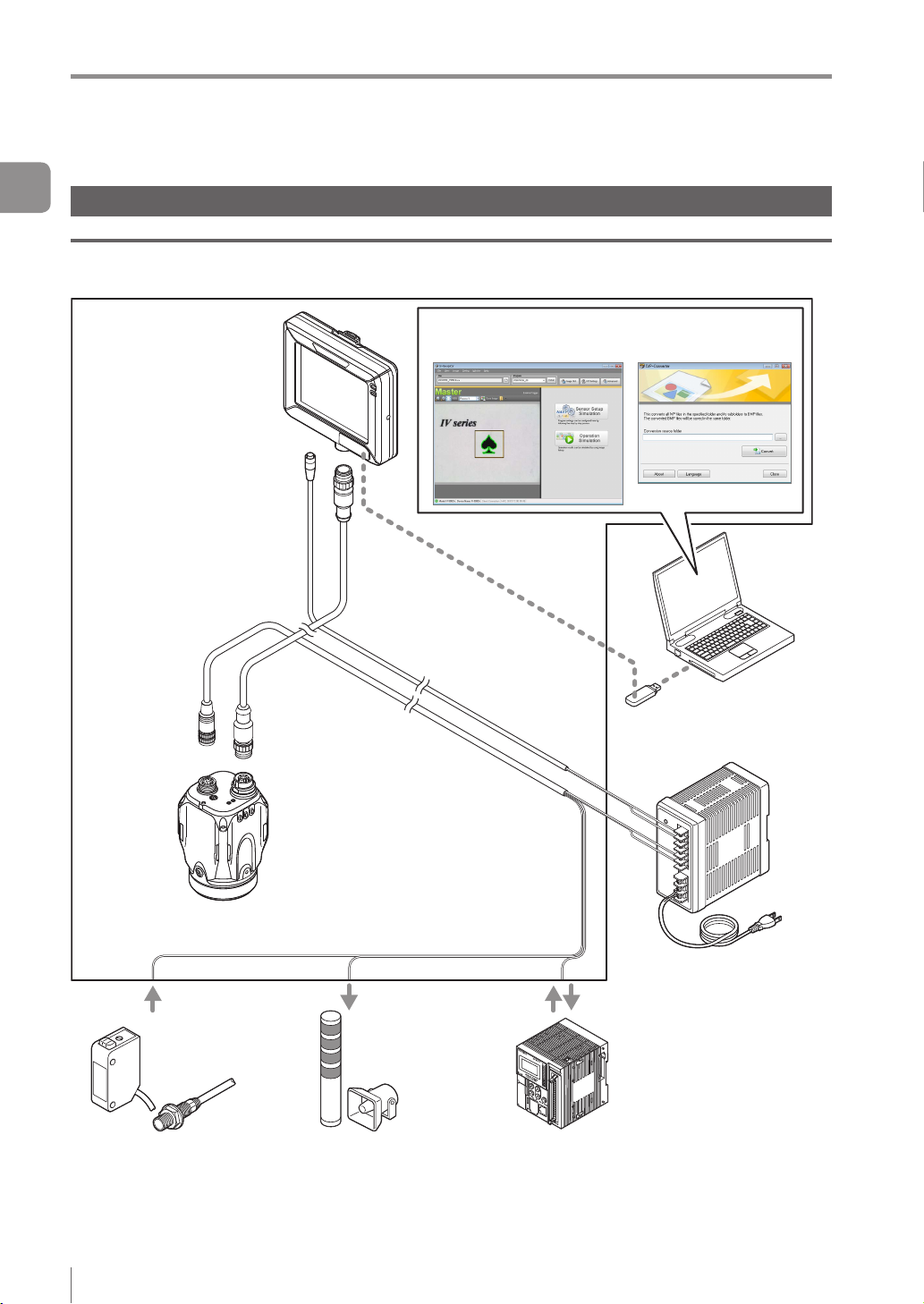
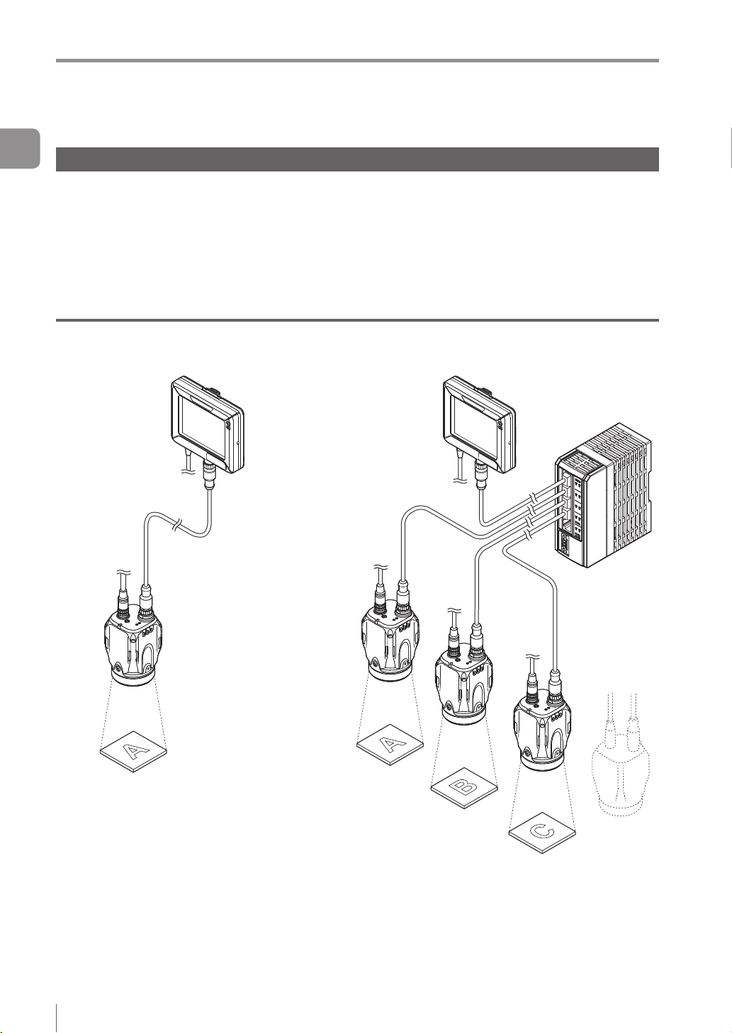
Basic congurations of IV Series
Connecting the monitor and single sensor
IV Series
Intelligent Monitor
IV-M30
Monitor power cable
(2m/5m/10m)
Ethernet communication
Simulator
(IV-Navigator) IVP-Converter
Monitor cable
(2m/5m/10m/20m)
Sensor
IV-500C
IV-500CA
IV-500M
IV-500MA
IV-150M
IV-150MA
IV-2000M
IV-2000MA
Photoelectric/
proximity sensor etc.
Sends the signal to the trigger
input when the target is detected.
(Optional)
Dome attachment
IV-D10
Polarizing lter attachment
OP-87436/OP-87437
Power I/O cable
(2m/5m/10m)
Indicator light/buzzer etc.
Alarm can be output by the
status output function.
USB memory
DC24V power
PLC
PLC can control the trigger input
and the status output function, and
can switch the program number.
1-2
- IV Series User's Manual (Monitor) -
Page 19
System Conguration
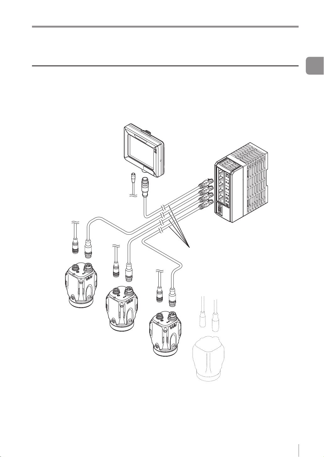
Connecting the monitor and multiple sensors
When the network is connected, the intelligent monitor (IV-M30) can be connected by selecting a single
sensor from among multiple sensors.
* Each sensor requires the power I/O cable.
* IV-M30 requires the power cable.
* A single monitor cannot be connected with multiple sensors at the same time.
Ethernet switch
Ethernet cable
(2m/5m/10m)
1
Getting Started
- IV Series User's Manual (Monitor) -
1-3
Page 20
Overview of IV Series
Overview of IV Series
1
Getting Started
IV Series
The IV Series is an all-in-one “Vision Sensor” featuring a camera, a light, and a controller. This sensor
can be attached easily so complicated detection operations such as detecting the shapes of parts with a
photoelectric switch can be achieved easily.
Operation condition settings require the intelligent monitor (IV-M30) or the IV software IV-Navigator (IV-H1).
After setting is completed, the sensor can be operated independently.
The sensor with monitor and the sensor with PC are connected via an Ethernet so network connection with
multiple sensors besides direct single connection can be performed.
Using with the intelligent monitor (IV-M30)
Power I/O
Direct connection
Functions of monitor
Setting the sensor
Monitoring the
operation screen
Monitoring the
statistical information
Reading the image
history
Network connection
Ethernet switch
1-4
Functions of sensor
Camera
Light
Image detection
I/O
Saving the image history
- IV Series User's Manual (Monitor) -
Page 21
Overview of IV Series
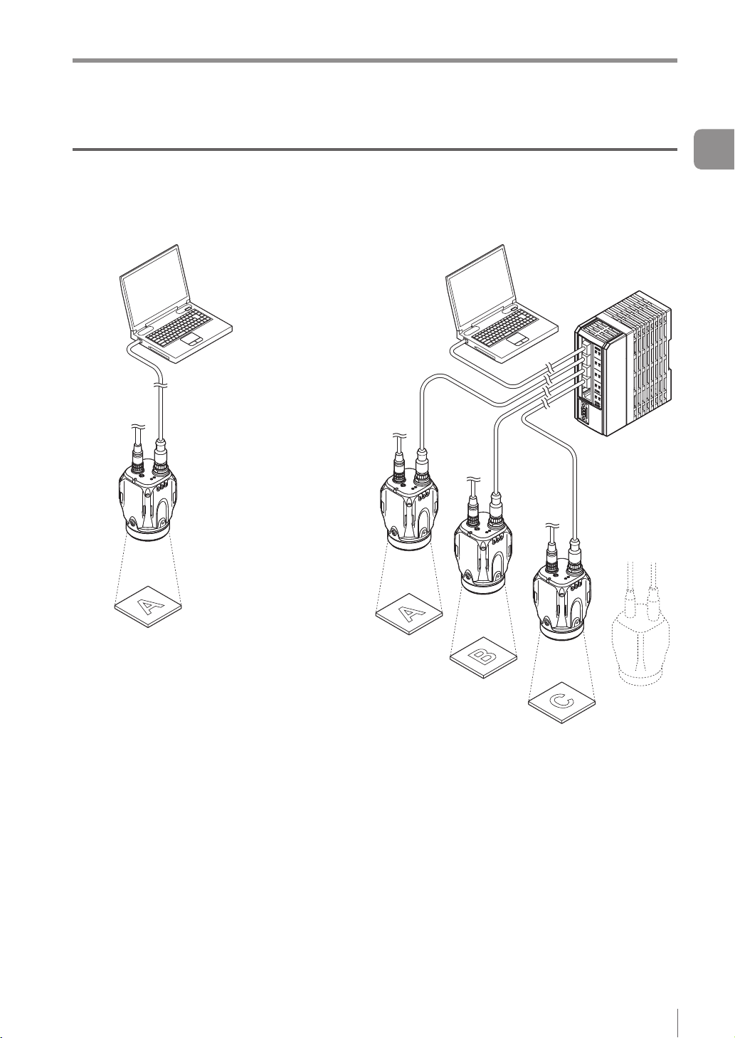
Using with the IV-Navigator (IV-H1)
The IV-Navigator has the same functions as the intelligent monitor (IV-M30).
For details of operations using the IV-Navigator, refer to “IV Series User's Manual (PC Software)”.
Direct connection
Power I/O
Functions of sensor
Functions of IV-Navigator
Setting the sensor
Monitoring the operation
screen
Monitoring the statistical
information
Reading the image history
Simulator
Camera
Light
Image detection
I/O
Saving the image history
Network connection
Ethernet switch
1
Getting Started
- IV Series User's Manual (Monitor) -
1-5
Page 22
Overview of IV Series
1
Getting Started
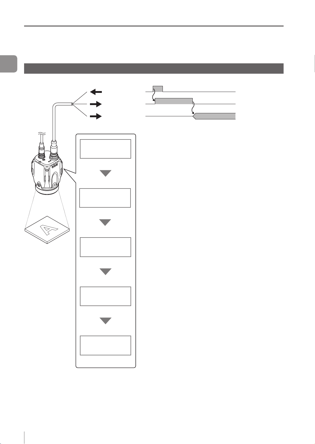
Judgment processing ow
This section describes the basic judgment processing ow of this device.
Trigger input
BUSY output
Total status
output
Trigger input
Imaging
Tool processing
Status output
Inputs the imaging startup signal by synchronizing to the
target position from a photoelectric switch or PLC.
Also, the trigger can be input at a regular interval with an
internal trigger function.
Light up the built-in light and image the target by using the
CMOS image sensor. BUSY output function turns ON.
According to the settings of a detection tool, the image of the target
is scanned for detecting whether a target is high or low quality.
Up to 16 detection tools can be set. Also, misaligned
positions of the target can be corrected by using the
position adjustment tool.
After the detection process is completed, the BUSY output
function turns OFF.
Outputs the status results.
When the total status result is OK, the total status output
is ON.
When the total status result is NG, the total status NG
output is ON.
1-6
Save images
- IV Series User's Manual (Monitor) -
Saves the image to the image history memory in the sensor.
Conditions for saving the image can be selected from “NG
only” or “All”.
Color type can save 100 images, and monochrome type
can save 300 images.
Page 23

MEMO
Overview of IV Series
1
Getting Started
- IV Series User's Manual (Monitor) -
1-7
Page 24
Checking the Package Contents
Checking the Package Contents
1
IV Series are constructed by each following model. Check that all the following packed items are packed
Getting Started
for each model you purchased before using.
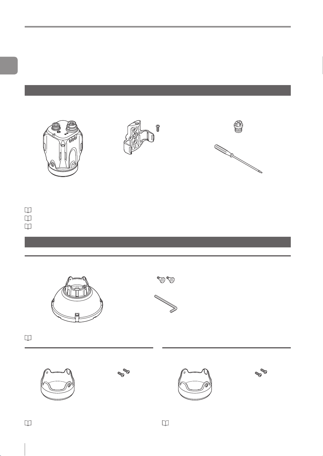
Sensor
IV-500C
IV-500CA
The mounting adapter is mounted with the sensors in the
default factory setting.
“Name and Function of Each Part” (Page 1-13)
“Mounting the Sensor” (Page 2-2)
“Cables” (Page 2-12)
Optional parts for the sensor
IV-150M
IV-150MA
Sensor x 1
IV-500M
IV-500MA
Mounting adapter x 1
Screw for mounting
adapter x 1
IV-2000M
IV-2000MA
Waterproof cap for Ethernet connector x 1
Flathead screwdriver x 1
(Manual focus type only)
Instruction Manual x 1
Dome attachment
IV-D10
Mounting screw x 2
Hexagon wrench
Dome attachment x 1
“Using the dome attachment” (Page 2-6)
(L-shaped) x 1
Polarized visible light lter attachment
OP-87436
Mounting screw x 2
Instruction Manual x 1
Polarized visible light
lter attachment x 1
“Using the polarizing lter attachment” (Page 2-7)
Instruction Manual x 1
Infrared polarization lter attachment
OP-87437
Mounting screw x 2
Instruction Manual x 1
Infrared polarization
lter attachment x 1
“Using the polarizing lter attachment” (Page 2-7)
1-8
- IV Series User's Manual (Monitor) -
Page 25
Checking the Package Contents
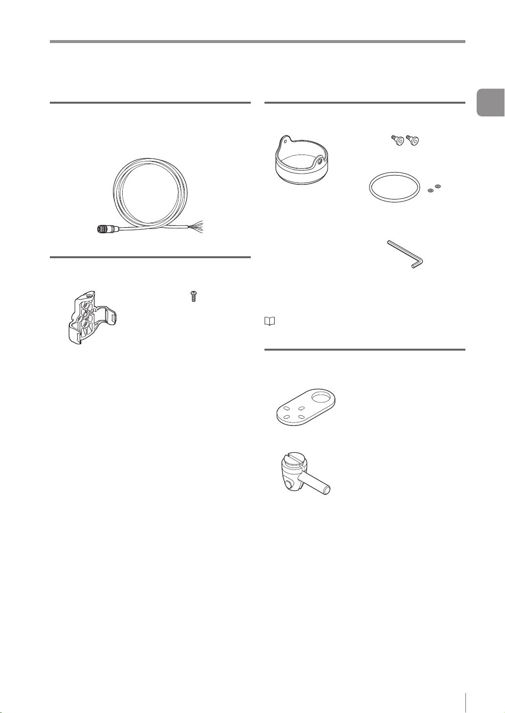
Power I/O cable (M12 12pin - strand wire)
OP-87440 (2m)
OP-87441 (5m)
OP-87442 (10m)
Power I/O cable (M12 12pin - strand wire) x 1
Mounting adapter
OP-87460
Screw for the mounting
adapter x 1
Mounting adapter x 1
Same as accessories for the sensor.
Optional parts in case of loss/damage.
Front cover (for replacement)
OP-87461
Mounting screw x 2
Front cover (for
replacement) x 1
Optional parts for replacement.
“Replacing the front cover” (Page A-41)
O-shaped ring
(Small x 2, Large x 1)
Hexagon wrench (L-shaped) x 1
Instruction Manual x 1
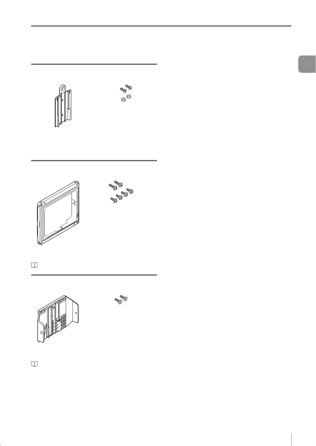
Bracket
OP-87685
Screw for the bracket and
nut x 1
1
Getting Started
Bracket A x 1
Bracket B x 1
- IV Series User's Manual (Monitor) -
Mounting screw x 4
1-9
Page 26
Checking the Package Contents
1
Getting Started
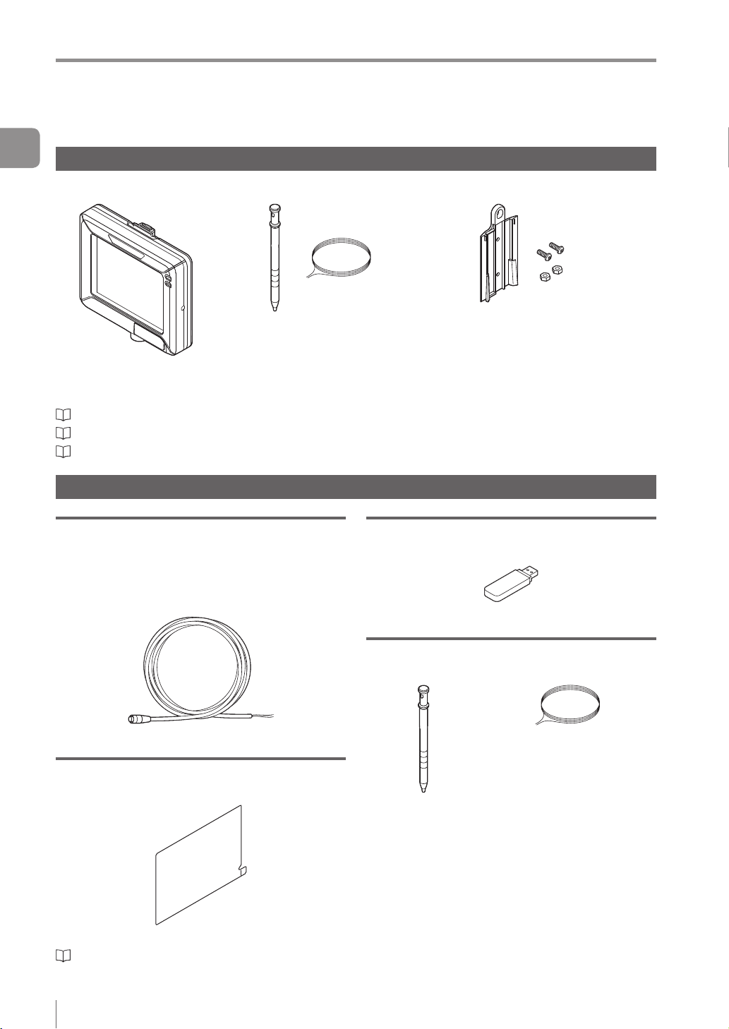
Intelligent Monitor
IV-M30
“Name and Function of Each Part” (Page 1-13)
“Mounting the Monitor” (Page 2-8)
“Cables” (Page 2-12)
Optional parts for the monitor
Monitor power cable (M8 4pin - strand wire)
OP-87443 (2m)
OP-87444 (5m)
OP-87445 (10m)
Monitor x 1
Stylus x 1
String for hanging the stylus x 1
USB memory (1GB)
OP-87502
Wall mounting adapter x 1
Screw for the adapter x 2
Hexagon nut x 2
Instruction Manual x 1
Starting Guide x 1
USB memory x 1
Monitor power cable (M8 4pin - strand wire)
Protection sheet
OP-87463
Protection sheet x 1
“Attaching the protection sheet” (Page A-41)
1-10
- IV Series User's Manual (Monitor) -
Stylus
OP-87462
String for hanging the
stylus x 1
Stylus x 1
Same as accessories for monitors.
Optional parts in case of loss/damage.
Page 27
Checking the Package Contents
Wall mounting adapter
OP-87464
Screw for the adapter x 2
Hexagon nut x 2
Wall mounting adapter x 1
Same as accessories for monitors.
Optional parts in case of loss/damage.
Panel mounting adapter
OP-87465
Mounting screw (lateral) x 2
Mounting screw (front) x 4
1
Getting Started
Panel mounting
adapter x 1
“Mounting to a panel” (Page 2-10)
DIN mounting adapter
OP-87466
Mounting screw (lateral) x 2
DIN mounting
adapter x 1
“Mounting to the DIN rail” (Page 2-11)
- IV Series User's Manual (Monitor) -
1-11
Page 28
Checking the Package Contents
1
Getting Started
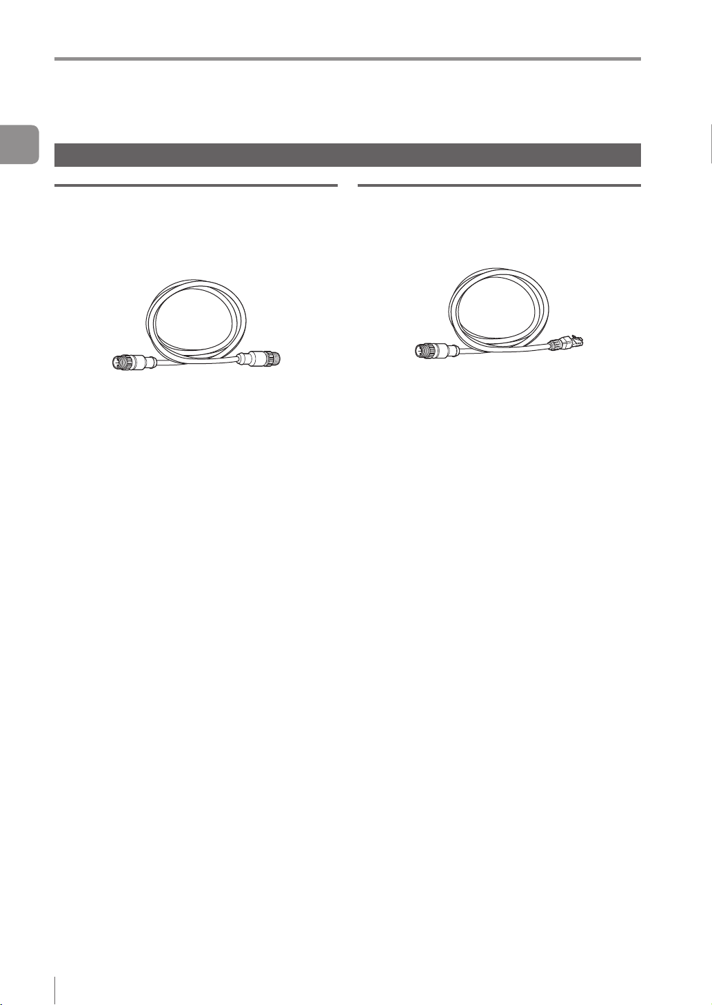
Communication Cable
Monitor cable (M12 4pin - M12 4pin)
OP-87450 (2m)
OP-87451 (5m)
OP-87452 (10m)
OP-87453 (20m)
Monitor cable (M12 4pin - M12 4pin) x 1
Ethernet cable (M12 4pin - RJ-45)
OP-87457 (2m)
OP-87458 (5m)
OP-87459 (10m)
Ethernet cable (M12 4pin - RJ-45) x 1
1-12
- IV Series User's Manual (Monitor) -
Page 29
Name and Function of Each Part
1
2
3
4
5
6
7
8
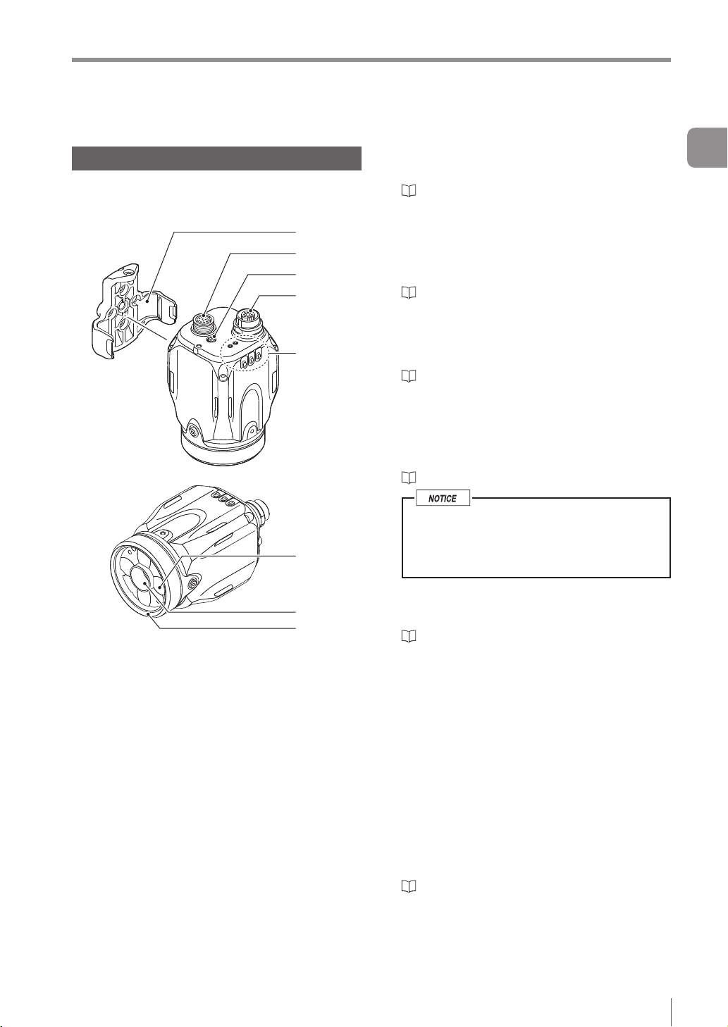
Name and Function of Each Part
Sensor
Name and function of each part of the
sensor
1 Mounting adapter
Use this for mounting and xing the sensor.
“Mounting the Sensor” (Page 2-2)
2 Connector for power I/O cable
Connector for connecting the power I/O cable.
Use this for supplying the power to the sensor
and for connecting with external devices.
“Cables” (Page 2-12)
3 Focusing position adjustment screw
(manual focus type only)
Adjusts the focus of the displayed image.
“Focus Adjustment” (Page 4-12)
4 Connector for monitor cable/Ethernet cable
Connector for connecting a monitor cable or
Ethernet cable. Use this for connecting the
monitor, PC, or Ethernet switch.
“Cables” (Page 2-12)
When the cable is not connected, attach
the waterproof cap for Ethernet connector
to maintain enclosure rating.
Tightening torque : 0.45 to 0.55 N·m
1
Getting Started
5 Indicator light
- IV Series User's Manual (Monitor) -
Indicates the operating status of the sensor.
“Operation of the indicator light” (Page 1-14)
6 Built-in light
LED light that illuminates the target
7 Camera
Images the object.
8 Front cover
Protects the camera and built-in lights.
The front cover is protected by the protection
sheet (blue) in the default factory setting. Remove
the sheet when the sensor is to be used.
Front cover for replacement is provided for
maintenance.
“Replacing the front cover” (Page A-41)
1-13
Page 30
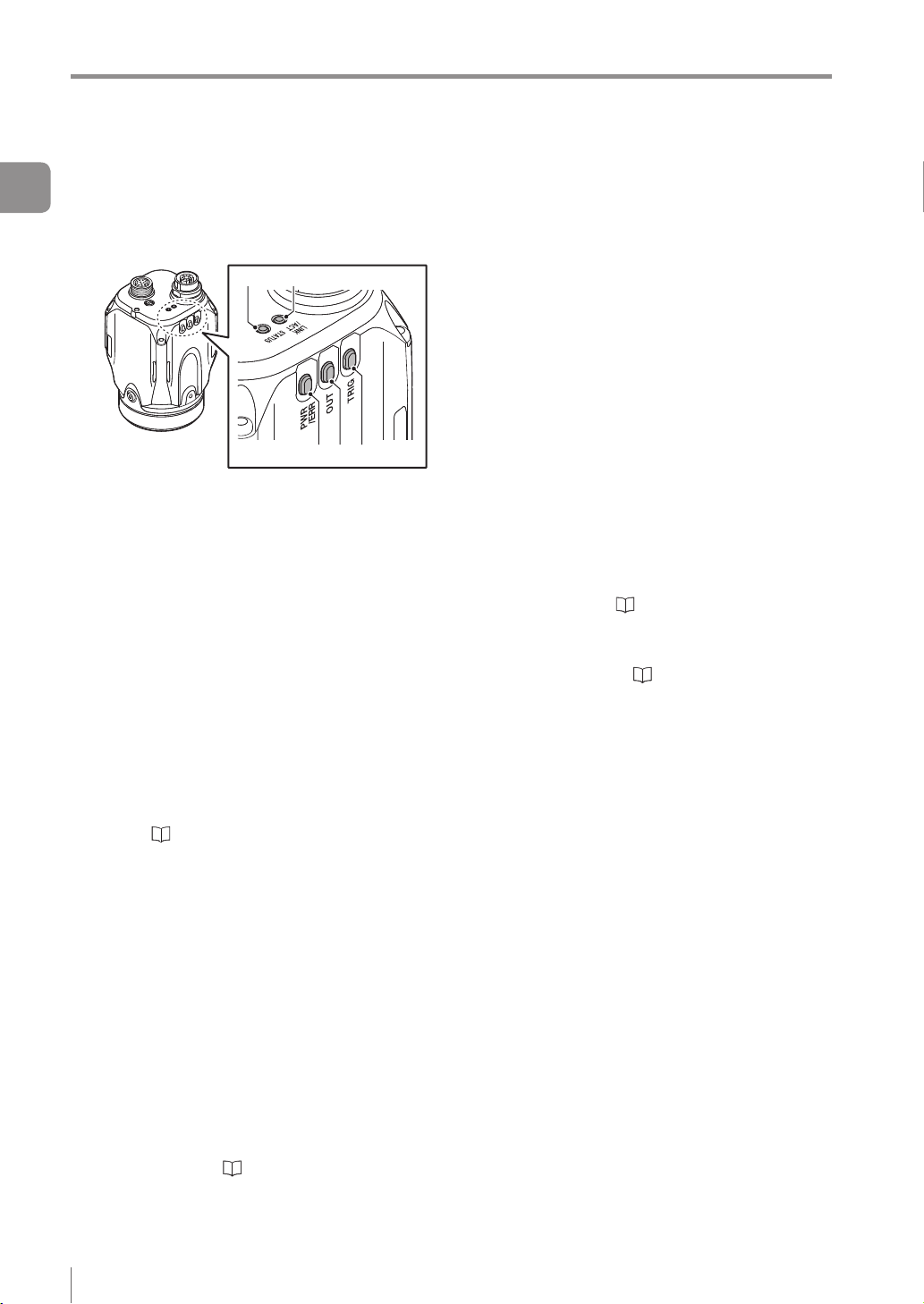
Name and Function of Each Part
1
Getting Started
Operation of the indicator light
Details on operations of the indicator light are
shown below.
1 PWR/ERR
Indicates the power supplying status to the
sensor and the error status of the sensor.
Green (ON) ...... Operating.
Green (Blink) .... Setting processing. Operation
Red (ON) .......... Unrecoverable error has
Red (Blink) ....... Recoverable error has
(OFF) ............... Power is not supplied.
For countermeasures when an error occurred,
refer to “Error Messages” (Page A-22).
2 OUT
Indicates the comprehensive result.
Green ...............
Red ..................
(OFF) ............... Setting processing.
Standby status until the rst
Orange (Blink) ..
“Focus adjustment for
4 5
1 2 3
is stopped. Blinks once a
second.
occurred.
occurred.
Adjusting the focusing position
(
manual focus only).
Comprehensive result is “OK”.
Comprehensive result is “NG”.
judge nishes after starting the
operation or after switching
the program number.
Indicates the focusing status
while adjusting the focusing
position with the blinking speed
(manual focus type only).
the manual focusing type”
(Page 4-14)
3 TRIG
Green light lights up (one-shot) according to
input of the internal or external trigger.
4 STATUS
Indicates the connection status within the monitor.
Green (ON) ...... Normally connected with
monitor.
Green (Blink) .... IP address has been retrieved
but the sensor is not correctly
connected with monitor.
(OFF) ............... IP address is not assigned.
Sensor is not correctly
connected with monitor.
Orange (Blink) ..
When the sensor cannot correctly connect with
the monitor, refer to “Remedy when the
Monitor cannot be Connected with the Sensor”
(Page A-28).
5 LINK/ACT
Indicates the linking status within monitor or
Ethernet switch.
Green (ON) ...... Normally linked.
Green (Blink) .... Normally linked, and the data
(OFF) ...............
Indicates the focusing status
while adjusting the focusing
position with the blinking speed
(manual focus type only).
“Focus adjustment for the
manual focusing type” (Page 4-14)
is sending/receiving.
Sensor is not normally linked.
1-14
- IV Series User's Manual (Monitor) -
Page 31

Name and Function of Each Part
10
Monitor
21
1 Power connector
Connects the monitor power cable.
“Cables” (Page 2-12)
2 Connector for the monitor cable/Ethernet
cable
Connector for connecting the monitor cable or
Ethernet cable. Used when connecting with the
sensor or Ethernet switch.
“Cables” (Page 2-12)
3 Unlock button
Push this button when dismounting the monitor from
the wall mounting adapter or DIN mounting adapter.
“Unmounting from the wall mounting adapter”
(Page 2-9)
“Unmounting from the DIN mounting adapter”
(Page 2-11)
4 Indicator light (PWR)
Indicates the operating status of the monitor.
3
4
5
6
7
8
9
Green (ON) ...... The power is turned ON.
Red (ON) ..........
Red (Blink) ....... Recoverable error occurred to
(OFF) ............... The power is turned OFF.
For countermeasures when an error occurred,
refer to
5 Indicator light (SENSOR)
Indicates the connecting status to the sensor.
Green (ON) ...... Connected normally to the
Green
(Slowly blinks)
(OFF) ............... It is not properly connected
If the monitor cannot correctly connect with the
sensor, refer to “Remedy when the Monitor
cannot be Connected with the Sensor” (Page A-28).
6 LCD monitor/Stylus
Displays the operation screen and setup screen.
Operates by touching the screen with the stylus.
7 USB connecting connector
Connector for connecting the USB memory.
Connector is protected by the cover.
“Saving the Sensor Settings and Images to a
USB Memory” (Page 6-18)
8 Stylus
Used to operate the touch-screen.
9 Stylus holder
Stores the stylus.
10
Strap holder
Holds the strap or hangs the stylus.
“Error Messages” (Page A-22).
1
Getting Started
Unrecoverable error occurred
to the sensor or monitor.
the sensor or monitor.
sensor.
... Linked normally but it is not
properly connected to the
sensor.
because it did not link
normally.
- IV Series User's Manual (Monitor) -
1-15
Page 32

Name and Function of Each Part
1
Getting Started
MEMO
1-16
- IV Series User's Manual (Monitor) -
Page 33

2
Installation and
Connection
This chapter explains how to mount the sensor and
monitor, and explains connection procedures.
2
Installation and Connection
Mounting the Sensor .........................................2-2
Mounting the Monitor ........................................2-8
Cables ...............................................................2-12
- IV Series User's Manual (Monitor) -
2-1
Page 34

Mounting the Sensor
Mounting the Sensor
Ground (functional ground) the drain cable
2
Installation and Connection
(FG) of the power I/O cable.
Mount and insulate the sensor. Use the
attached mounting adapter to insulate.
Sensor case has been grounded. If the sensor
is not insulated, the electric potential and
noises may cause a damage or malfunction.
Do not place the sensor in the environment
that exceeds the limit of sensor's resistance
to the environment, or environment that
propagates the vibration directly to the
sensor. Those may cause a damage or
malfunction.
Checking the view and installed distance
For IV Series, installed distance between the view
and object is different depending on the type of the
sensor. Check the type of the sensor to be used
and its view, and place it in the proper distance.
View H
Indicator light
View V
Manual focus type needs to adjust the focusing
position after installed. Reserve the enough
space to adjust and install it.
At the time of installation, it is better to enable
the position or direction adjustment of the
sensor by installing the adjustment system at
the sensor mounting area.
View and optical axis have individual differences.
Adjust the position by checking the actual image
at the time of installation.
Place the sensor where no ambient light has
effect. Ambient light includes solar light, lights of
other devices, and photoelectric sensors. Also,
be careful when the light intensity of the ambient
light changes. Use the shield to protect when the
location cannot be changed.
Place the sensor where no object can block out
the internal light or the view of the sensor.
Detection may become unstable due to the
lights if multiple sensors are placed nearby each
other. Delay the timing of external trigger or use
the shield to avoid interference.
Installed distance
WD
View V = View H x 0.75
(H : V = 4 : 3)
The indicator light of
the sensor side is the
front surface of an
image.
2-2
- IV Series User's Manual (Monitor) -
Page 35

Standard range type (color/monochrome)
100
200
150
300
400
500
600
250
210
100
150
10 20 30 4012 36
1500
1000
2000
2500
10045 200 300 400
Installed distance WD (mm)
50
0
Short range type
5025 70 100 150130 200
View H (mm)
Mounting the Sensor
2
Installation and Connection
50
Installed distance WD (mm)
0
View H (mm)
Long range type
500
300
Installed distance WD (mm)
0
View H (mm)
The value of View H and V will be a half of the
value on the gures above when using the digital
zooming function (monochrome type only).
- IV Series User's Manual (Monitor) -
2-3
Page 36

Mounting the Sensor
Mounting the sensor
2
Mounting the mounting adapter
Installation and Connection
Use the mounting adapter (accessory or OP-87460)
to mount the sensor.
The mounting adapter is mounted with the sensors
in the default factory setting. Remove it from the
sensor.
“Unmounting the sensor” (Page 2-5)
Mounting on the wall
Screw : M3 x 4
Use the commercially available screws which
have head thickness of 3 mm or lower.
Tightening torque : 1.0 N·m or lower
Mounting the sensor onto the mounting adapter
Mount the sensor to the left and right
1
stopper on the mounting adapter.
Sensors cannot be mounted on the side with the
indicator light.
Indicator light
Push the sensor to the
stopper of the xing screw
Mounting from the jig side
Screw : M4 x 4
Use the commercially available screws.
Tightening torque : 1.5 N·m or lower
For details on mounting hole dimensions, refer to
“Dimensions” (Page 8-6).
2-4
- IV Series User's Manual (Monitor) -
Push until you hear the clicking sound from
the both side stoppers
Fix the mounting adapter and sensor
2
using the attached screws.
Screw : M3 x 1
Use the attached screws.
Tightening torque : 0.45 to 0.55 N·m
Remove the
protection sheet
Page 37

Unmounting the sensor
Mounting the Sensor
Dismount the screw.
1
Pull out the stopper of the mounting
2
adapter and unmount the sensor.
Pull out the
stopper
2
Installation and Connection
- IV Series User's Manual (Monitor) -
2-5
Page 38

Mounting the Sensor
Mounting the attachment
2
Using the dome attachment
Installation and Connection
Dome attachment can be used for the standard
range type and short range type sensor.
Do not remove the front cover of the sensor.
Use the dome attachment at a correct
installation distance. Failure to do so may lose
the effect of the dome attachment.
Adjust the brightness with the dome attachment
mounted.
“Auto Brightness Adjustment” (Page 4-11)
For the color type, adjust the white balance with
the dome attachment mounted.
“White Balance (for color type only)” (Page 6-41)
Fix the dome attachment with attached
2
dedicated screws.
Screw : Dedicated screw x 2
Use the attached dedicated screws.
Tightening torque : 0.25 to 0.35 N·m
Mounting the dome attachment
Mount the attachment by aligning the
1
concave part of the dome attachment with
the mounting screw of the front cover of
the sensor.
Screw hole for
mounting the
Front cover
mounting screw
Concave part
attachment
Concave part
Installed distance of the dome
attachment
62 to 112 mm from the front face of the sensor
(0 to 50 mm from the front face of the dome attachment)
Sensor type
Standard range type
Short range type
Installed distance
from the front face
of the sensor
62 to 112 mm
Target
(0 to 50 mm)
2-6
- IV Series User's Manual (Monitor) -
Page 39

Using the polarizing lter attachment
Do not remove the front cover of the sensor.
There are the polarized visible light lter
attachment (OP-87436) and the infrared
polarization lter attachment (OP-87437). Use
the correct polarization lter attachment in
accordance with the illuminant of the sensor light.
Failure to do so may lose the effect.
Adjust the brightness with the polarization lter
attachment mounted.
“Auto Brightness Adjustment” (Page 4-11)
For the color type, adjust the white balance with
the polarization lter attachment mounted.
“White Balance (for color type only)” (Page 6-41)
Mount the attachment by aligning the
1
concave part of the polarizing lter
attachment with the mounting screw of
the front cover of the sensor.
Mounting the Sensor
Fix the polarizing lter attachment with
2
the attached dedicated screws.
Screw : M2.5 x 2
Use the attached dedicated screws.
Tightening torque : 0.25 to 0.35 N·m
Remove the protection
sheet (blue)
2
Installation and Connection
Front cover
mounting screw
Concave part
Screw hole for
mounting the
attachment
Concave part
- IV Series User's Manual (Monitor) -
2-7
Page 40

Mounting the Monitor
Mounting the Monitor
Mounting to a wall
Use the wall mounting adapter (accessories or OP-
2
87464).
Installation and Connection
Hang it on the hook with the wall mounting adapter
mounted to the monitor, or mount the monitor to the
wall mounting adapter mounted on the wall.
Hanging on the hook
For operation take the monitor from the hook and
operate it while holding it in your hands.
Mount the monitor to the wall mounting
1
adapter by aligning the stopper of the wall
mounting adapter to the groove on the
rear monitor.
Slide the monitor down all the way, and conrm
that the monitor is locked.
Mounting with the wall mounting adapter
The monitor can be operated by the following
methods.
Unhang to pick up the monitor from the hook and
operate it.
Operate it while mounted on the wall.
Mount the wall mounting adapter to the wall.
1
Mounting by creating a screw hole in the wall
Screw : M3 x 2
Use commercially available screws.
Tightening torque : 0.27 to 0.33 N·m
Mounting by creating a plated through
hole on the panel
Screw : M3 x 2, Nut : M3 x 2
Use the attached screws and nuts.
Tightening torque : 0.27 to 0.33 N·m
Stopper
Hang the monitor on the hook.
2
2-8
- IV Series User's Manual (Monitor) -
Page 41

Mount the monitor to the wall mounting
2
adapter by aligning the stopper of the wall
mounting adapter to the groove on the
rear monitor.
Slide the monitor down all the way, and conrm
that the monitor is locked.
Mounting the Monitor
Unmounting from the wall mounting adapter
Unlock the monitor from the wall mounting adapter
by pulling toward the unlock button. And slide up to
unmount the monitor mounted to the adapter.
Unlock
2
Installation and Connection
Stopper
- IV Series User's Manual (Monitor) -
2-9
Page 42

Mounting the Monitor
3.5
+1
+1
Mounting to a panel
Operate the monitor by mounting it to the panel
2
side such as a control board.
Installation and Connection
Mount the panel adapter (OP-87465) to the monitor,
and mount it to the panel.
Mounting to a panel
Connect the power cable and monitor
1
cable to the monitor.
“Cables” (Page 2-12)
Mount the panel adapter to the monitor
2
and x it with the attached screws.
Screw : M3, 11 mm long, with 2 washers
Use the attached screws.
Tightening torque : 0.27 to 0.33 N·m
Mount the monitor with the panel adapter
3
mounted to the control board from the
rear side, and x it with the screws.
Mountable board thickness : 1 to 4 mm
Screw : M3, 7 mm long, with 4 washers
Use the attached screws.
Tightening torque : 0.5 N·m or lower
Strap holder
Stylus can be hung from the strap holder using
the hanging string (accessory).
Panel cutting dimension
(Panel cutting square hole dimension)
111
-0
-0
92
(Panel cutting square hole dimension)
(Circular hole position for screw)
11 0
4-φ
100
(Circular hole position for screw)
2-10
- IV Series User's Manual (Monitor) -
Page 43

Mounting to the DIN rail
Mount the DIN mounting adapter (OP-87466) to the
monitor, and mount it to the DIN rail.
The monitor can be operated by the following methods.
Pick up the monitor from the DIN mounting
adapter and operate it.
Operate it while mounted on the DIN rail.
Mounting using DIN mounting adapter
Mount the monitor to the DIN mounting
1
adapter.
Slide the monitor until the end of the stopper,
and conrm that the monitor is locked.
Mounting the Monitor
Adjust the position of the DIN mounting
2
adapter and the DIN rail by pulling down
the stopper of the adapter, and then push
up the stopper to lock it.
Stopper
Unmounting from the DIN mounting adapter
Unlock the monitor from the DIN mounting adapter
by pulling toward the unlock button. And slide up to
unmount the monitor mounted to the adapter.
2
Installation and Connection
Stopper
Fixing to the DIN mounting adapter
To x the monitor to the DIN mounting adapter,
use the attached screws.
Screw : M3 x 2
Use the attached at head screw.
Tightening torque : 0.27 to 0.33 N·m
Unlock
- IV Series User's Manual (Monitor) -
2-11
Page 44

Cables
Cables
Connecting the power I/O cable of the sensor
2
Installation and Connection
Adjust the pins of the connector for the
1
power I/O cable and pin connection of the
cable connector, and connect the cable to
the sensor.
Wire each cable according to its intended
3
purpose.
Selecting NPN output
When NPN is selected in the Polarity (Page 3-11)
External device
Brown (DC24V)
Black/White/
Gray/Orange
(OUT)
Pink/Yellow/
Light Blue/Purple/
Green/Red
(IN)
Load
IN
DC24V
OUT
Adjust the pins and the
pin connection
Tighten the connector by turning the screw-
2
on connector in the clockwise direction.
Tightening torque of the screws needs to be 1.0
to 1.5 N·m.
Blue (0V)
Drain wire (FG)
Black (OUT1) / White (OUT2) /
Gray (OUT3) / Orange (OUT4)
Pink (IN1 : External trigger) / Yellow (IN2) /
Light Blue (IN3) / Purple (IN4) /
Green (IN5) / Red (IN6)
Use it by assigning the optional function
to OUT1 to OUT4 and IN2 to IN6.
Selecting PNP output
When PNP is selected in the Polarity (Page 3-11)
Brown (DC24V)
Pink/Yellow/
Light Blue/Purple/
Green/Red
(IN)
Black/White/
Gray/Orange
(OUT)
Blue (0V)
(NPN)
External device
(PNP)
OUT
DC24V
IN
Load
When connecting the connector, insert it
without tipping and tighten it well. If the
tightening is weak, vibration can loosen
the connector and cause bad connections.
Also, the enclosure rating may not be
maintained with loose connection.
* Indication is retighten approximately
90° to 120° with tools such as pliers
after tightening with hands.
2-12
- IV Series User's Manual (Monitor) -
Drain wire (FG)
Black (OUT1) / White (OUT2) /
Gray (OUT3) / Orange (OUT4)
Pink (IN1 : External trigger) / Yellow (IN2) /
Light Blue (IN3) / Purple (IN4) /
Green (IN5) / Red (IN6)
Use it by assigning the optional function
to OUT1 to OUT4 and IN2 to IN6.
Page 45

Cables
Wiring
color
Brown DC24V - + side of power
Blue 0V -
Black OUT1 Total Status (N.O.)
White OUT2 BUSY (N.O.)
Gray OUT3 Error (N.O.)
Orange OUT4 OFF
Pink IN1 External trigger ↑
Yellow IN2 OFF
Light Blue IN3 OFF
Purple IN4 OFF
Green IN5 OFF
Red IN6 OFF
Drain FG - Insulated frame
Cable specication Brown/Blue/Black/White/Gray/Orange : AWG25
The output cable assignment can be changed.
“4. Output Assignment (Setting Details of Outputting to Output Line)” (Page 4-60)
N.O./N.C. can be changed.
“Output Settings” (Page 6-27)
The input cable assignment can be changed.
“Input Settings” (Page 6-26)
Name
Assigning
default value
- side of power
GND of input-output cable
Output assignable function
Total Status
Tot. StatusNG
RUN
BUSY
Error
Pos. Adj.
Judge result of each tool (Tool 1 to Tool 16)
Logical operation result of each tool (Tool 1 to Tool 4)
OFF (not used)
Set external trigger.
Rising timing (↑) or falling timing (↓) can be set.
Input assignable function
Program bit0 to bit4
Clear Error
Ext. Master Save
OFF (not used)
Pink/Yellow/Light Blue/Purple/Green/Red : AWG28
With braided shield cable (with drain cable)
Description
2
Installation and Connection
Individually insulate the non-used input-output cables.
For input cables of this sensor, connect with non-contact output (transistor output/SSR output).
For contact output (relay output), incorrect input may be operated due to the contact bouncing.
- IV Series User's Manual (Monitor) -
2-13
Page 46

Cables
DC24V
DC24V
DC24V
DC24V
Specication of I/O circuit and
current of the sensor
2
Installation and Connection
Input circuit
No-voltage input (When the NPN
output is selected)
When the NPN is selected in the Polarity (Page
3-11), the circuit becomes no-voltage input circuit.
External power supply is not necessary.
ON voltage : 2 V or lower
OFF current : 0.1 mA or lower
ON current : 2 mA (short circuit)
+3.3V
Main circuit
* Pink (IN1 : External trigger) / Yellow (IN2) /
Light Blue (IN3) / Purple (IN4) / Green (IN5) / Red (IN6)
Use by assigning the optional functions to IN2 to 6
Voltage input (When the PNP output is
selected)
When the PNP is selected in the Polarity (Page
3-11), the circuit becomes voltage input circuit.
Input maximum rating : 26.4 V
ON voltage : 15 V or higher
ON current : 2 mA (for 24V)
OFF current : 0.2 mA or lower
Brown
IN1 - IN6
*
Blue
Brown
0V
Output circuit
When the NPN output is selected
When the NPN is selected in
3-11), the circuit becomes open collector NPN output
circuit.
Maximum rating : 26.4 V, 50 mA
Remaining voltage : 1.5 V or lower
Main circuit
* Black (OUT1) / White (OUT2) / Gray (OUT3) /
Orange (OUT4)
Use by assigning the optional functions to OUT1
to OUT4
When the PNP output is selected
When the PNP is selected in
3-11), the circuit becomes open collector PNP output
circuit.
Maximum rating : 26.4 V, 50 mA
Remaining voltage : 2 V or lower
Main circuit
the Polarity
Brown
Overcurrent protection circuit
*
Blue
the Polarity
Brown
Overcurrent protection circuit
*
(Page
Load
OUT1 - OUT4
0V
(Page
OUT1 - OUT4
Load
Main circuit
IN1 - IN6
* Pink (IN1 : External trigger) / Yellow (IN2) /
Light Blue (IN3) / Purple (IN4) / Green (IN5) / Red (IN6)
Use by assigning the optional functions to IN2 to 6
2-14
*
0V
Blue
- IV Series User's Manual (Monitor) -
0V
Blue
* Black (OUT1) / White (OUT2) / Gray (OUT3) /
Orange (OUT4)
Use by assigning the optional functions to OUT1
to OUT4
Page 47

Connecting the power cable of the monitor
Align the arrow mark of the power cable
1
and the direction of the front monitor, and
connect the cable to the monitor.
Wire to the power supply.
3
Brown (DC24V)
Monitor power cable
(2m/5m/10m)
Cable specication Brown/Blue : AWG24
Blue (0V)
Cables
2
Installation and Connection
DC24V
Arrow mark
Turn the screw-on connector in the
2
clockwise direction to tighten it.
- IV Series User's Manual (Monitor) -
2-15
Page 48

Cables
Connecting the sensor and the monitor
2
Installation and Connection
Connecting directly
Connect the sensor and monitor using the monitor
cable.
Connecting via network
Connect each Ethernet cable to the monitor and
sensor.
Connect the other side of the Ethernet cable to the
Ethernet switch.
Ethernet switch
Monitor cable
(2m/5m/10m/20m)
Ethernet cable
(2m/5m/10m)
For details on connecting the monitor cable, refer to
“Connecting the monitor cable/Ethernet cable”
(Page 2-17).
2-16
- IV Series User's Manual (Monitor) -
For details on connecting the Ethernet cable, refer
to
“Connecting the monitor cable/Ethernet cable”
(Page 2-17).
The sensor and monitor do not support PoE
(Power over Ethernet). Supply power using
the power cable.
Page 49

CablesCables
Connecting the monitor cable/ Ethernet cable
This section describes the details on connecting the
monitor cable/Ethernet cable using the example of
connecting the monitor cable to the sensor.
Align the pin connection parts of the
1
monitor cable/Ethernet cable connector
with three pins of the cable connector,
and connect the cable to the sensor.
Align the pins and
the pin connection
Repeat the steps (1) and (2) and when you cannot
tighten the screw by hand any more, use a tool
such as pliers for further tightening. Tightening
torque, retorque degree, and acceptable spaces
between connectors are shown below.
Monitor cable/Ethernet cable
(OP-87450/OP-87451/OP-87452/OP-87453/
OP-87457/OP-87458/OP-87459)
Tightening torque : 0.8 to 1.0 N·m
Retightening degree : 5 to 10°
Spaces between connectors (reference value)
For sensors : 0 mm
For monitors : 2.2 mm
If the connector cable tightening is weak,
vibration may loosen the connector and cause
bad connections or cable disconnections.
Also, the enclosure rating may not be
maintained with loose connection.
Properly follow the procedures above and
tighten the connector completely.
Check the spaces between the monitor cable/
Ethernet cable and the cable connector.
For sensors
2
Installation and Connection
* Same procedures for monitors.
Tighten the connector by turning the
2
screw-on connector in the clockwise
direction. When connecting the connector,
insert it without inclination while pushing
in and tighten it well.
(2)
When the screw stops rotating by the
locking mechanism, further tighten it
while pushing.
(1)
Tighten the screw-on connector
* Same procedures for monitors.
- IV Series User's Manual (Monitor) -
Spaces between
connectors
Spaces between
connectors
For monitors
2-17
Page 50

Cables
2
Installation and Connection
MEMO
2-18
- IV Series User's Manual (Monitor) -
Page 51

3
Basic Operation
This chapter explains the contents of the monitor
display and operation of the IV Series, basic
operation ow, and operation when turning on the
power for the rst time.
It also explains procedures to restore the sensor
and monitor to the default factory settings and basic
operation of monitor.
Overview of Screen and Operation ..................3-2
Basic Operation Flow ........................................3-4
Operation when the Power is Turned on .........3-5
Setting to the Factory Default ........................3-12
Basic Operation for the Monitor .....................3-14
3
Basic Operation
- IV Series User's Manual (Monitor) -
3-1
Page 52

Overview of Screen and Operation
Overview of Screen and Operation
This section explains monitor displays and operation.
For details of what can be set on each screen and its operation, see to the applicable references.
Run screen
Images and judges based on
3
Basic Operation
the judgment condition.
“Starting an Operation”
(Page 5-2)
Switching ON/OFF of
the menu display
Full-screen display/Zooming
Use the [Zoom] button to
enlarge the view of the monitor
“Switching the display
to the full-screen mode”
(Page 5-5)
“Enlarging the image
display” (Page 5-6)
A B
Monitor Settings
Sets each function of the monitor.
“Setting the Advanced Monitor Information”
(Page 6-45)
Tool display
Select the display patterns
of tools from OFF / Window /
Process 1 / Process 2
“Selecting a display method
for tools” (Page 5-7)
Statistics display
Displays statistical information
of status on the monitor.
“Displaying the statistical
information” (Page 5-10)
Histogram display
Displays histogram of status
on the monitor.
“Displaying the
histogram” (Page 5-12)
3-2
- IV Series User's Manual (Monitor) -
Page 53

Sensor Setup Menu
Sets condition to judge a target.
“Displaying the Sensor Setup
Menu Screen” (Page 6-7)
A B
Overview of Screen and Operation
Program list
Checks or initializes
the program.
“Things can be performed
with the program functions”
(Page 6-8)
Settings Navigator
Sets the program to be used
for judgment.
“Chapter 4 Settings Navigator
(Setting the Judgment Condition)”
(Page 4-1)
3
Basic Operation
Sensor Advanced
Performs the sensor advanced settings.
“Setting the Extended Functions of
the Sensor” (Page 6-25)
A
B
Limit Adjustment
Adjusts the judgment threshold.
Tool Auto Tuning
Automatically adjusts threshold of
tool and extraction conditions of
Color Area/Area tool in accordance
with OK/NG image.
Sensor Image History
Operates the sensor image history.
“Sensor Image History (Conrming the
Images whose Status Result is NG)”
(Page 6-14)
USB Memory
Sets the operation when using USB memory.
“Saving the Sensor Settings and Images
to a USB Memory” (Page 6-18)
“Adjusting Thresholds for
Judgment” (Page 5-14)
“Tool Auto Tuning (Automatically
Adjusting the Judgment
Condition)” (Page 5-15)
- IV Series User's Manual (Monitor) -
3-3
Page 54

Basic Operation Flow
Basic Operation Flow
3
Basic Operation
Mounting, connecting, and wiring the sensor and monitor
Mount the sensor and monitor, and then connect and wire the cable.
“Chapter 2 Installation and Connection” (Page 2-1)
Turning on the power
Turn on the power of the sensor and monitor, and then perform the initial startup setting.
“Operation when the Power is Turned on” (Page 3-5)
Settings Navigator
Create the program to be used for operation in [Settings Navigator] (Sensor Setup).
STEP 1: Setting of image optimization
Set the image optimization for clearly imaging a target. Adjust the image for
dening the differences in the high and low-quality-target.
Set the trigger option, and adjust the brightness and imaging focus.
“1. Image Optimization (Clearly Image a Target)” (Page 4-6)
STEP 2: Registration of a master image
Image the high-quality-target and register the master image to serve as the
reference of judgment.
“2. Master Registration (Registering an Image as a Reference for Judgment)”
(Page 4-20)
STEP 3: Tool setting
Set the tool to judge a target.
Set the tool onto the master image and set the threshold for judgment. Up to 16
detection tools and 1 position adjustment tool in one program can be set.
“3. Tool Settings (Setting the Judgment Method for Targets)” (Page 4-28)
STEP 4: Output assignment
Assign the function to output to each output line (OUT1 to OUT4).
“4. Output Assignment (Setting Details of Outputting to Output Line)” (Page 4-60)
Starting the operation/adjustment
Switch the settings screen to the run screen, and start the operation. If the setting is
inappropriate, adjust the thresholds and tool settings (Tool Auto Tuning).
“Chapter 5 Operating/Adjusting” (Page 5-1)
3-4
- IV Series User's Manual (Monitor) -
Page 55

Operation when the Power is Turned on
Operation when the Power is Turned on
Operation ow when the power is
turned on
Turn on the power
(1)
Initial start-up of the
monitor
Direct Connection
Network Connection
(2)
Initial start-up of
the sensor
(3)
Sensor settings menu
Run
(5)(4)
Connecting...
(1) When the power of the monitor is turned on for
the rst time, set the display language, date and
time, and the connection method with the sensor.
For the connection method with the sensor, there
are Direct Connection and Network Connection.
“Operation for initial startup of the monitor
(Direct Connection)” (Page 3-6)
“Operation for initial startup of the monitor
(Network Connection)” (Page 3-7)
(2) When the power of the sensor is turned on for
the rst time, set the polarity.
“Operation for initial startup of the sensor”
(Page 3-11)
The Sensor Setup Menu screen opens. Set the
(3)
activation condition in Settings Navigator. After the
setting is completed, operation begins.
“Chapter 4 Settings Navigator (Setting the
Judgment Condition)” (Page 4-1)
(4) After the second time of starting the monitor
and sensor, the operation begins when the
power is turned on.
“Chapter 5 Operating/Adjusting” (Page 5-1)
(5) When the connection is failed, the process
remains in the connecting screen.
“Remedy when the Monitor cannot be
Connected with the Sensor” (Page A-28)
3
Basic Operation
The sensor can be independently operated.
- IV Series User's Manual (Monitor) -
3-5
Page 56

Operation when the Power is Turned on
Operation for initial startup of the monitor (Direct Connection)
Turn on the power of the monitor.
1
3
Basic Operation
The screen to select the language opens.
Select the language to be displayed on
2
the monitor and tap the [OK] button.
[English] is selected in the default setting.
Set the current date and time, and tap the
3
[OK] button.
Turn on the power of the sensor.
5
Turn on the power of the sensor before the monitor
is restarted by tapping the [OK] button in step 6.
Tap the [OK] button.
6
The monitor restarts and connects to the
sensor.
When the monitor is connected with the sensor
for the rst time, set the polarity of the sensor. For
the details of procedures, refer to “Operation
for initial startup of the sensor” (Page 3-11).
After the second time connecting with the sensor,
the run screen opens.
Move to the item to be set by the [←] or [→]
button and enter the numbers.
Tap the [Delete] button to reset the display of
the selected item.
Select the [Direct Connection] button and
4
tap the [OK] button.
To use the FTP client function or eld network,
select the [Network Connection] button.
The Complete Conguration screen opens.
3-6
- IV Series User's Manual (Monitor) -
When the connection is unavailable with the frozen
connection screen, refer to “Remedy when
direct connection is unavailable” (Page A-28).
For the direct connection, the IP address is
automatically set.
If the PC is directly connected with the sensor
when the PROFINET function is being used,
the PROFINET function will stop. To use the
PROFINET function again, restart the sensor.
Page 57

Operation for initial startup of the monitor (Network Connection)
When connecting to a network, let engineers who
are knowledgeable about networks handle it.
Setting the network address of the monitor
Operation when the Power is Turned on
Select the [Network Connection] button
4
and tap the [OK] button.
3
Basic Operation
Turn on the power of the monitor.
1
The screen to select the language opens.
Select the language to be displayed on
2
the monitor and tap the [OK] button.
[English] is selected in the default setting.
Set the current date and time, and tap the
3
[OK] button.
The Complete Conguration screen opens.
Tap the [OK] button.
5
The Network Settings screen opens.
Tap each [Edit] button of the IP address,
6
subnet mask, and default gateway.
The screen to set each item opens.
Move to the item to be set by the [←] or [→]
button and enter the numbers.
Tap the [Delete] button to reset the display of
the selected item.
- IV Series User's Manual (Monitor) -
At the initial startup or initialization of
the monitor, the monitor starts up with
192.168.10.1 as the IP address.
If there is a device with the same IP address
on the network, change the IP address before
connecting the monitor to the network.
3-7
Page 58

Operation when the Power is Turned on
Set the IP Address, Subnet Mask, and
7
Default Gateway individually, and then tap
the [OK] button.
Searching for a sensor to be connected
Automatically searches for a sensor on the network
and connects with it.
3
Basic Operation
The system returns to the network setup screen.
Tap the [OK] button.
8
The monitor restarts.
After restarted, the Sensor Connect screen
opens.
IP address
The search time is about 10 seconds.
Searching range and retrievable number of units
are as follows.
Sensor with no IP address (default) :
A maximum of 8 units can be retrieved within a
range that the BOOTP packet from the sensor
reaches (Page A-40).
Sensor with IP address :
A maximum of 16 units can be retrieved on
the local network to which the monitor is
connected.
Turn on the power of the sensor.
1
Tap the [Search Sensor] button.
2
Searching for sensor begins.
There are two ways to set the sensor to be
connected. For details of procedures, refer to
each reference.
When the sensor on the network is
searched
“Searching for a sensor to be connected”
(Page 3-8)
When the sensor is specied by the IP
address
“Specifying sensor to be connected by IP
address” (Page 3-10)
3-8
- IV Series User's Manual (Monitor) -
When the searching is nished, the searched
result will be displayed.
If no sensor is found, refer to “When the
connection cannot be established by searching
for the sensor” (Page A-30).
Page 59

Operation when the Power is Turned on
When a sensor with no IP address is found
Empty
When a sensor with an IP address is found
IP address
When multiple sensors are found, select
3
the sensor to be connected with the [<] or
[>] button.
Connect to the sensor.
4
When connecting to the sensor with no IP
address
Tap the [Connect] button.
The conrmation dialog appears.
3
Basic Operation
Tap the [Yes] button to copy the network
settings of the monitor.
When copying is completed, the information
screen opens.
Tap the [OK] button.
The sensor network setup screen opens.
The conrmation dialog appears.
Tap the [OK] button.
Tap each [Edit] button of the IP address, subnet
mask, and default gateway, and set these items
individually.
When the monitor's IP address is copied,
the sensor's and monitor's IP address will be
duplicated. Make sure to change the IP address.
- IV Series User's Manual (Monitor) -
IP address
3-9
Page 60

Operation when the Power is Turned on
The system returns to the network setup screen
for the sensor to be connected.
3
Basic Operation
Tap the [Connect] button.
When the monitor is connected with the sensor
for the rst time, set the polarity of the sensor. For
the details of procedures, refer to “Operation
for initial startup of the sensor” (Page 3-11).
After the second time connecting with the sensor,
the run screen or the Sensor Setup Menu screen
opens.
When connecting to the sensor with set IP
address
Tap the [Connect] button.
Specifying sensor to be connected by IP address
Used when the IP address of the sensor to be
connected is dened beforehand.
Turn on the power of the sensor.
1
Tap the [Specify Sensor] button.
2
Enter the IP address of the sensor to be
3
connected and tap the [Connect] button.
The monitor connects to the selected sensor
and the run screen or the Sensor Setup Menu
screen opens.
3-10
- IV Series User's Manual (Monitor) -
The run screen or the Sensor Setup Menu
screen opens.
If the monitor cannot connect with the sensor, refer
to “When the connection cannot be established
by specifying the sensor” (Page A-31).
Page 61

Operation for initial startup of the sensor
When the monitor is connected to the sensor in
the default setting, the screen to select the polarity
(NPN or PNP) opens.
After the polarity is selected, set up the sensor in
Settings Navigator.
For details of the Polarity, refer to “Specication
of I/O circuit and current of the sensor” (Page 2-14).
Select the Polarity of the sensor and tap
1
the [OK] button.
Operation when the Power is Turned on
3
Basic Operation
The Sensor Setup Menu screen opens.
Tap the [Sensor Setup] button and set up
2
the program.
For details of the Settings Navigator, refer to
“Chapter 4 Settings Navigator (Setting the
Judgment Condition)” (Page 4-1).
- IV Series User's Manual (Monitor) -
3-11
Page 62

Setting to the Factory Default
Setting to the Factory Default
Tap the [System] button and then the
Initializing the sensor
Initializes information set in the sensor and uses
factory default setting.
3
[Initialize Sensor] button.
3
Basic Operation
The following settings will not be initialized.
Polarity (Switching NPN/PNP)
(Page 6-28)
Network Settings (IP Address / Subnet Mask /
Default Gateway / Port number (TCP))
(Page 6-31)
To initialize the registered programs individually,
refer to “Initializing a program” (Page 6-13).
Set the menu display of the monitor to ON
1
and tap the [Sensor Setup] button.
The Sensor Setup Menu screen opens.
Tap the [Sensor Advanced] button.
2
Tap the [Go] button.
4
The conrmation dialog appears.
Tap the [OK] button.
5
Initialization begins. After initialization is completed,
the initialization completion screen opens.
Tap the [OK] button.
6
The Sensor Advanced screen opens.
3-12
The system returns to the Sensor Advanced
screen.
- IV Series User's Manual (Monitor) -
Page 63

Initializing the monitor
Initializes information set in the monitor and uses
factory default setting.
Tap the [OK] button.
4
Setting to the Factory Default
The following settings will not be initialized.
Language (Page 6-51)
Time (Page 6-51)
Set the menu display of the monitor to ON
1
and tap the [Monitor Settings] button.
The Monitor Settings screen opens.
Tap the [System] button and then the
2
[Initialize Monitor] button.
Tap the [Go] button.
3
Initialization begins. After initialization is completed,
the initialization completion screen opens.
Tap the [OK] button.
5
The monitor restarts.
After restarting, set the display language, date
and time, and the connection method with the
sensor.
For the connection method with the sensor,
there are Direct Connection and Network
Connection.
“Operation for initial startup of the monitor
(Direct Connection)” (Page 3-6)
“Operation for initial startup of the monitor
(Network Connection)” (Page 3-7)
3
Basic Operation
The conrmation dialog appears.
- IV Series User's Manual (Monitor) -
3-13
Page 64

Basic Operation for the Monitor
Basic Operation for the Monitor
Editing the value with the slider
The value of a trigger interval and the threshold of
each tool can be edited.
This section explains how to edit the value with
3
the slider using an example of a trigger interval in
[Internal].
Basic Operation
In the Image Optimization settings of
1
the Settings Navigator, tap the [Internal]
button in [Trigger Options].
The slider appears on the monitor.
Setting by the [+] / [-] button
By tapping the [+] / [-] button, the value of a
trigger interval increases or decreases (slider
slides in accordance with the value changed).
The value
is updated
according to the
slider position
Tap the [+] / [-] button to slide the
slider
For the slider which sets both upper and lower
limit, select the slider to be set and tap the [+] /
[-] button to set it.
Set the trigger interval.
2
Setting by the slider
Touch the slider, and then slide it to the right or
left to set the trigger interval. According to the
slider position, the value of a trigger interval is
updated.
The value
is updated
according to the
slider position
Slide the slider to the right or left
Setting by inputting a value
By tapping the ▼ button of the trigger interval,
the screen to input a value opens.
Input the value of a trigger interval and tap the
[OK] button.
Tap the ▼ button
Input the value
of a trigger
interval
By tapping the button, the value can be
reset to 0.
By tapping the
can be deleted.
button, the last number
3-14
- IV Series User's Manual (Monitor) -
Page 65

Editing the tool window
The tool window displayed when the tool is set in
the Settings Navigator can be edited to any size or
direction.
This section explains how to edit the tool window
using an example of [Outline] tool.
In the tool setting of the Settings
1
Navigator, tap the [Add Tool] button and
tap the [Outline] button.
The tool window of the Outline tool will be
displayed at the center of the monitor.
Basic Operation for the Monitor
Changing the size of the tool window
By touching either side of the tool window,
will be displayed. The height or width of
or
the tool window can be changed by touching
and dragging it.
By touching one of the corners of the tool
window,
tool window can be changed by touching and
dragging it.
will be displayed. The size of the
3
Basic Operation
Tool window
Set the tool window of the Outline tool.
2
Selecting the shape of the tool window
On the screen to set the detection tool, the
screen to select the shape of the tool window
opens by tapping the [Window Shape ] button.
[ Rect] or [ Circle] can be selected.
Rect
Moving the tool window
By tapping inside the tool window, will be
displayed. Move the tool window by touching
and dragging it.
Circle
When the [ Circle] is selected in the Window
shape settings, the size of the circle can be
changed by touching and dragging the outline
of the circle.
Changing the direction of the tool window
By touching and dragging the arrow mark on
the upper right of the tool window, the direction
of the tool window can be changed.
The operations when an image is enlarged by
the [Zoom] button are as follow.
Slide the slider while tapping inside the tool
window to move the tool window.
Slide the slider while tapping outside the tool
window to change the image display position.
- IV Series User's Manual (Monitor) -
3-15
Page 66

Basic Operation for the Monitor
Inputting characters
The programs or tools to be displayed on the
monitor can be named arbitrary.
This section explains how to input characters using
3
an example of [Program Name].
Basic Operation
According to the items to be set, the number of
characters, character types, and characters which
can be input are different.
On the Sensor Setup Menu screen, tap the
1
[Detail] button.
Edit the program name.
3
(1) (2) (3) (4)
(7) (8) (9)
(1) Program name
Displays a program name being editing.
(2) [←] button
Moves a cursor position to the left.
(3) [→] button
Moves a cursor position to the right.
(5)
(6)
Select the program to change the name
2
and tap the [Edit] button.
Select the
program
(4) [Delete] button
Deletes one character to the left of the cursor.
(5) Number of characters which can be input
Displays a number of characters that can be
input as a program name.
(6) Character button
Inputs an arbitrary character.
According to selection of the [Upper/Lower]
button, characters that can be input are different.
(7) [Upper/Lower] button
Switches a character to be input to uppercase /
lowercase.
(8) [Cancel] button
Cancels a character input setting and returns to
the Program details screen.
(9) [OK] button
Saves a character input setting and returns to
the Program details screen.
After the characters are entered, tap the
4
[OK] button.
3-16
- IV Series User's Manual (Monitor) -
Page 67

Selecting the le in the USB memory
This section explains how to select the le in the USB
memory connected to the monitor using an example
of [Transfer Program Settings].
Select the le to be sent.
5
Basic Operation for the Monitor
(1)
(2)
On the Sensor Setup Menu screen, tap the
1
[USB Memory] button.
Tap the [Transfer Program Settings] button.
2
The conrmation dialog appears.
Tap the [OK] button.
3
The folder and le in the USB memory are displayed.
Select the folder that stores the data and
4
tap the [OK] button.
(3)
(4) (5) (6) (7) (8) (9)
(1) Folder display
Displays a tree of currently displayed folder.
(2) [Up One Folder]
By selecting the [Up One Folder] and tapping
the [OK] button, you can go to the upper
hierarchy of currently displayed folder.
(3) File / Folder display
Displays a le and folder stored in the currently
displayed folder.
By selecting the folder and tapping the [OK]
button, you can go into the selected folder.
(4) [First] button
Moves to top page in the folder.
(5) [<<] button
Moves to previous page in the folder.
(6) [>>] button
Moves to next page in the folder.
(7) [Last] button
Moves to last page in the folder.
3
Basic Operation
Select
The folder and le stored in the selected folder
will be displayed.
- IV Series User's Manual (Monitor) -
(8) [Cancel] button
Cancels a setting and returns to the Sensor
Setup Menu screen.
(9) [OK] button
When the folder is selected, you can go into the
selected folder. When the le is selected, the
selection of a le will be determined.
After selecting a le, tap the [OK] button
6
and proceed to the next setting.
3-17
Page 68

Basic Operation for the Monitor
3
Basic Operation
MEMO
3-18
- IV Series User's Manual (Monitor) -
Page 69

4
Settings Navigator
(Setting the Judgment Condition)
This chapter explains the functions and operations
of the [Settings Navigator].
Settings Navigator .............................................4-2
Basic Operation of the Settings Navigator .....4-3
1. Image Optimization
(Clearly Image a Target) ....................................4-6
2. Master Registration (Registering
an Image as a Reference for Judgment) .......4-20
3. Tool Settings
(Setting the Judgment Method for Targets) ..4-28
4. Output Assignment (Setting Details of
Outputting to Output Line) .............................4-60
Display Method of
Extended Functions Menus ............................4-66
4
Settings Navigator (Setting the Judgment Condition)
- IV Series User's Manual (Monitor) -
4-1
Page 70

Settings Navigator
Settings Navigator
In the Settings Navigator, the setting items of the program required for judging the target with the sensor
are set in each step. While sequentially following the steps with navigation buttons, perform the setting
using the menu buttons in accordance with the Settings Navigator guide.
Navigation
button
4
Settings Navigator (Setting the Judgment Condition)
Menu button
Flow in the Settings Navigator
STEP 1. Image Optimization settings
Set the image optimization for clearly imaging a target. Adjust the image for
dening the differences in the high and low-quality-target. Set the trigger
option, adjust the brightness and imaging focus.
“1. Image Optimization (Clearly Image a Target)” (Page 4-6)
STEP 2. Registration of a master image
Image the high-quality-target and register the master image to serve as the
reference of judgment.
“2. Master Registration (Registering an Image as a Reference for Judgment)”
(Page 4-20)
Settings
Navigator guide
4-2
STEP 3. Tool settings
Set the tool to judge a target. Set the tool onto the master image and set the
threshold for judgment. Up to 16 detection tools and 1 position adjustment
tool in one program can be set.
“3. Tool Settings (Setting the Judgment Method for Targets)” (Page 4-28)
STEP 4. Output assignment
Assign the function to output to each output line (OUT1 to OUT4).
“4. Output Assignment (Setting Details of Outputting to Output Line)”
(Page 4-60)
- IV Series User's Manual (Monitor) -
Page 71

Basic Operation of the Settings Navigator
Basic Operation of the Settings Navigator
Perform the following operation.
Starting the Settings Navigator
Turn on the power of the sensor and
1
monitor.
When the sensor is in the following condition,
the Sensor Setup Menu will be displayed.
Proceed to step 5.
When the power is turned on for the rst time
If all programs are not being set
If the sensor is being setting up
6
When the program which has not been set
in step 5 is selected
Tap the [Start] button.
4
Settings Navigator (Setting the Judgment Condition)
Tap the [Menu] button.
2
The menu bar appears.
Tap the [Sensor Setup] button.
3
The conrmation dialog appears.
Tap the [OK] button.
4
The Sensor Setup Menu screen opens.
Tap the [Sensor Setup] button.
5
The Settings Navigator guide screen opens.
Tap the [OK] button and start setting [1. Image
Optimization].
“1. Image Optimization (Clearly Image a
Target)” (Page 4-6)
When the program which has been set in
step 5 is selected
Tap the [Start] button. Or tap the shortcut button
for each step.
Shortcut button
The Settings Navigator guide screen of the
selected step opens.
Tap the [OK] button and start the setting.
“1. Image Optimization (Clearly Image a
Target)” (Page 4-6)
“2. Master Registration (Registering an Image
as a Reference for Judgment)” (Page 4-20)
“3. Tool Settings (Setting the Judgment Method for
Targets)” (Page 4-28)
“4. Output Assignment (Setting Details of
Outputting to Output Line)” (Page 4-60)
The startup screen of the Settings Navigator opens.
- IV Series User's Manual (Monitor) -
The Navi guide can be turned OFF if the
display of the Navi guide screen is not needed.
4-3
Page 72

Basic Operation of the Settings Navigator
Settings Navigator screen and operation ow
This section explains each setting screen to be displayed in the Settings Navigator and the operation ow.
For details of the contents that can set on each setting screen and its operation, refer to the applicable
references.
4
A
Settings Navigator (Setting the Judgment Condition)
A
1. Image Optimization
“1. Image Optimization
(Clearly Image a Target)”
(Page 4-6)
A
2. Master Registration
“2. Master Registration
(Registering an Image as a
Reference for Judgment)”
(Page 4-20)
A
A
3. Tool Settings
“3. Tool Settings (Setting the
Judgment Method for Targets)”
(Page 4-28)
4. Output Assignment
“4. Output Assignment
(Setting Details of Outputting
to Output Line)” (Page 4-60)
4-4
- IV Series User's Manual (Monitor) -
Page 73

Displaying the Settings Navigator guide
When the “Navi Guide” is ON
The step guide appears only the rst time
when moving to each step.
The extended functions guide appears only
the rst time when displaying the Extended
Functions menu.
To display the step guide and extended
functions guide again, nish and then start the
Settings Navigator again.
The function guide always appears when
touching the following function buttons.
Focus Adjustment / Fine Tune Outline / Margin /
Color Extraction / Brightness Extraction /
Fixed Reference Area
Basic Operation of the Settings Navigator
Tap the [Yes] button.
3
The settings in the Settings Navigator will be
saved and the system returns to the Sensor
Setup Menu screen.
By tapping the [No] button, the conrmation
dialog to cancel the settings appears. By
tapping the [Yes] button, the screen closes
without saving the settings.
By tapping the [Cancel] button, the system
returns to the Settings Navigator screen.
Finishing without completing the step
Tap the [Save] button at the upper right of
1
the screen.
4
Settings Navigator (Setting the Judgment Condition)
You can display the function guide by tapping
the
button on the upper right of the screen
when operating the corresponding functions.
When the “Navi Guide” is OFF
The step guide / extended functions guide /
function guide are not displayed
Finishing the Settings Navigator
This section explains the procedure for nishing the
Settings Navigator.
Finishing by completing all steps
Set all steps in the Settings Navigator.
1
Tap the [Complete] button at the lower
2
right of the [Output Assignment] screen.
When the required settings are completed
The conrmation dialog to save appears.
When the required settings are not
completed
The conrmation dialog to nish appears.
By tapping the [Yes] button, the conrmation
dialog to save appears.
By tapping the [No] button, the system returns
to the Settings Navigator screen.
The required settings have not been completed
yet. Even if the [OK] button is tapped, the
proper operation cannot be performed.
Tap the [Yes] button.
2
The settings in the Settings Navigator will be
saved and the system returns to the Sensor
Setup Menu screen.
When the program setting is changed,
the conrmation dialog to save appears.
- IV Series User's Manual (Monitor) -
By tapping the [No] button, the conrmation
dialog to cancel the settings appears. By
tapping the [Yes] button, the screen closes
without saving the settings.
By tapping the [Cancel] button, the system
returns to the Settings Navigator screen.
4-5
Page 74

1. Image Optimization 2. Master Registration 3. Tool Settings 4. Output Assignment
1. Image Optimization
Setting the Image Optimization
In this section, set the Image Optimization for taking an image of a target. Adjust the image for dening
differences in high and low-quality-targets.
Trigger Options
A trigger in this manual indicates the timing to start imaging with the built-in camera of the sensor. In the
Trigger Options, set the timing to image a target within the eld of view of this device. This device can
4
Settings Navigator (Setting the Judgment Condition)
image a target at any timing and can image continuously.
“Setting the Trigger Options” (Page 4-8)
“Checking the view and installed distance” (Page 2-2)
Auto Brightness Adjustment
The sensor images a target by receiving the reected light of the built-in light exposed to a target using
the CMOS image sensor.
In the Auto Brightness Adjustment, a target can be imaged with an appropriate brightness by
automatically adjusting the light intensity and shutter speed according to the shape and surface
condition (color, shininess, material).
“Auto Brightness Adjustment” (Page 4-11)
Focus Adjustment
Adjusts the focus of lens. Adjusts for clearly imaging the shape of a target. Auto focus can adjust the
focusing position automatically.
“Focus Adjustment” (Page 4-12)
(Clearly Image a Target)
4-6
- IV Series User's Manual (Monitor) -
Page 75

1. Image Optimization 2. Master Registration 3. Tool Settings 4. Output Assignment
Trigger Options Auto Brightness Adjustment Focus Adjustment Extended functions
Main screen for the Image Optimization
This section explains the main screen for the Image Optimization.
(1)
(2)
(7) (8) (9) (10) (11)
(1)
[Back] button
The system returns to the Sensor Setup Menu
screen.
(2)
Image taken by the sensor
Displays an image taken by the sensor.
The image type to be displayed differs depending
on the settings screen.
(3)
[Save] button
Saves the settings and returns to the Sensor
Setup Menu screen.
(4)
[Image Type] display
Displays the image type.
................
Displays an image taken by
the currently imaging sensor
(5)
[Trig] button
Displayed when an external trigger is set.
The [Trig] and [Pause] button switches by each
time the button is tapped.
[Trig] .................
Images by temporarily inputting
the internal trigger. Tap this
button when the position is to be
dened while a target is being
imaged in a state where the
external trigger cannot be input.
[Pause] ............. Finishes the imaging with
internal trigger.
(6)
[Zoom] button
Switches to full-screen display and the image of
the sensor can be zoomed.
“Switching the display to the full-screen mode”
(Page 5-5)
(3)
(4)
(5)
(6)
4
Settings Navigator (Setting the Judgment Condition)
(7)
Extended functions display button
Displays the extended functions menu for the
Image Optimization.
“Extended functions for the Image Optimization”
(Page 4-16)
(8)
[Trigger Options] button
Performs the settings for the Trigger Options.
“Setting the Trigger Options” (Page 4-8)
(9)
[Auto Brightness Adjustment] button
Automatically adjusts brightness.
“Auto Brightness Adjustment” (Page 4-11)
(10)
[Focus Adjustment] button
Automatically adjusts focus.
.
“Focus Adjustment” (Page 4-12)
(11)
[Next] button
Proceeds to "2. Master Registration".
“2. Master Registration (Registering an Image as
a Reference for Judgment)” (Page 4-20)
- IV Series User's Manual (Monitor) -
4-7
Page 76

1. Image Optimization 2. Master Registration 3. Tool Settings 4. Output Assignment
Trigger Options Auto Brightness Adjustment Focus Adjustment Extended functions
Setting the Trigger Options
A trigger in this manual indicates the timing to start imaging with the built-in camera of the sensor. In the
Trigger Options, set the timing to image a target within the eld of view of this device. This device can
image a target at any timing, and can image continuously.
Settings for the Trigger Options
4
Settings Navigator (Setting the Judgment Condition)
Items Description Setting range
Trigger
(Trigger type)
Trigger interval
Trigger Delay
Select the type of the timing to
start imaging.
Set when the [Internal] is
selected in the trigger type
setting.
Set an interval (cycle) to
automatically start imaging.
Set when the [External] is
selected in the trigger type
setting.
Used when the output timing
of the sensor for the trigger
occurrence and the imaging
timing of this device cannot be
synchronized.
This device starts imaging after
the time set in the trigger delay
of the trigger input passes.
Default
value
Internal
Starts imaging continuously within
the time interval specied in the
trigger interval setting.
External
Starts imaging with the external
trigger synchronized with the
target's motion from a photoelectric
sensor or PLC installed outside.
The time (trigger delay) between
inputting the trigger until imaging
starts can be set.
1 to 10000 ms 50 ms
0 to 1000 ms 0 ms
Internal
4-8
- IV Series User's Manual (Monitor) -
Page 77

Internal trigger
1. Image Optimization 2. Master Registration 3. Tool Settings 4. Output Assignment
Trigger Options Auto Brightness Adjustment Focus Adjustment Extended functions
Trigger interval Trigger interval
(1)
Internal trigger
Imaging/
internal processing
Status output
(1) The trigger will be input automatically according to the trigger interval settings.
(2) Performs the internal processing after the imaging.
(3) Outputs the status result.
External trigger
(2)
(3)
External trigger
Imaging/
internal processing
Status output
Trigger delay
(1)
(2)
(3)
4
Settings Navigator (Setting the Judgment Condition)
(1) Start imaging by inputting the trigger at an arbitrary timing.
When the trigger delay interval is set, the imaging start time will be delayed in the specied period.
(2) Performs the internal processing after imaging.
(3) Outputs the status result.
- IV Series User's Manual (Monitor) -
4-9
Page 78

1. Image Optimization 2. Master Registration 3. Tool Settings 4. Output Assignment
Trigger Options Auto Brightness Adjustment Focus Adjustment Extended functions
Setting the Trigger Options
Start the Settings Navigator.
1
“Starting the Settings Navigator” (Page 4-3)
Display the main screen for the Image
2
Optimization.
4
Settings Navigator (Setting the Judgment Condition)
“Settings Navigator screen and operation ow”
(Page 4-4)
Tap the [Trigger Options] button.
3
Set the trigger interval or trigger delay.
5
When the [Internal] is selected in step 4
Set the trigger interval within the range of 1 to
10000 ms.
If the internal trigger time is shorter than the
processing time (Page 5-40), a trigger error
occurs.
“Internal trigger” (Page 7-3)
“Error Messages” (Page A-22)
The screen to set the Trigger Options opens.
Select the trigger type.
4
Select the [Internal] or [External] button.
When the [External] is selected in step 4
Set the trigger delay within the range of 1 to
1000 ms.
The setting of the trigger interval and trigger
delay can be changed by using the slider or
inputting the value.
“Editing the value with the slider” (Page 3-14)
After the setting is completed, tap the [OK]
6
button.
The system returns to the main screen for the
Image Optimization.
4-10
- IV Series User's Manual (Monitor) -
Page 79

1. Image Optimization 2. Master Registration 3. Tool Settings 4. Output Assignment
Trigger Options Auto Brightness Adjustment Focus Adjustment Extended functions
Auto Brightness Adjustment
In the Auto Brightness Adjustment, the target
can be imaged with an appropriate brightness by
automatically adjusting a light intensity, an exposure
time and an imaging mode according to the shape
and surface condition (color, shininess, material).
Start the Settings Navigator.
1
“Starting the Settings Navigator” (Page 4-3)
Display the main screen for the Image
2
Optimization.
“Settings Navigator screen and operation ow”
(Page 4-4)
Tap the [Auto Brightness Adjustment]
3
button.
Tap the [OK] button.
4
The system returns to the main screen for the
Image Optimization.
The brightness of an image can be adjusted
manually.
“Advanced Brightness Adjustment” (Page 4-18)
During the auto brightness adjustment, the
sensor automatically images a target by
inputting the internal trigger regardless of the
Trigger Options settings.
Do not move a target during the auto brightness
adjustment. The focus may not be adjusted
correctly.
4
Settings Navigator (Setting the Judgment Condition)
After the adjustment is completed, the
“Brightness adjustment completed.” message
appears.
- IV Series User's Manual (Monitor) -
4-11
Page 80

1. Image Optimization 2. Master Registration 3. Tool Settings 4. Output Assignment
Trigger Options Auto Brightness Adjustment Focus Adjustment Extended functions
Focus Adjustment
Adjusts the focusing position for clearly imaging the
shape of a target.
Adjusting the methods differ depending on the type
of the sensor connected (manual focusing type/
auto focusing type).
Auto focusing type
4
Settings Navigator (Setting the Judgment Condition)
The focus position is adjusted automatically.
When the [Auto] button is tapped, the focusing
position is adjusted automatically again.
The focus can be adjusted manually with the
slider displayed on the monitor.
When the sensor detects multiple matching
positions for the focusing position, the optional
positions are marked on the slider. Select
the focus position from the detected optional
positions.
Manual focusing type
Turn the focus adjustment screw using the
attached athead screwdriver to adjust the
focusing position.
Focus adjustment for the auto focusing type
Start the Settings Navigator.
1
“Starting the Settings Navigator” (Page 4-3)
Display the main screen for the Image
2
Optimization.
“Settings Navigator screen and operation ow”
(Page 4-4)
Tap the [Focus Adjustment] button.
3
When the [Auto Focus Adj Pos] (Page 6-42) is
set to [Common], the following dialog appears.
Place a target at the appropriate position.
“Mounting the Sensor” (Page 2-2)
Do not move a target during the focus adjustment.
The focus may not be adjusted correctly.
The guide screen for the Focus Adjustment opens.
Tap the [OK] button.
4
The focusing position is adjusted automatically.
4-12
- IV Series User's Manual (Monitor) -
Page 81

1. Image Optimization 2. Master Registration 3. Tool Settings 4. Output Assignment
Trigger Options Auto Brightness Adjustment Focus Adjustment Extended functions
Adjust the focusing position as needed.
5
When the focusing position is to be
adjusted automatically again
When the [Auto] button is tapped, the focusing
position is adjusted automatically again.
When the focusing position is to be
adjusted manually
Adjust the focus by the slider.
After the setting is completed, tap the [OK]
6
button.
The system returns to the main screen for the
Image Optimization.
When the [Cancel] button is tapped, the focus
will be reset to the previous position.
During the auto adjustment, the sensor
automatically images a target by inputting the
internal trigger regardless of the Trigger Options
settings (Page 4-8). Also, when the continuous
lighting (Page 4-18) is set, the sensor images
with the ash lighting.
The auto adjustment searches the positions that
can be focused over the entire area regardless
of the imaging area settings (Page 4-17).
4
Settings Navigator (Setting the Judgment Condition)
For details of settings by using the slider, refer to
“Editing the value with the slider” (Page 3-14).
When multiple focusing positions exist
When there are multiple positions that can be
focused, the sensor adjusts to the closest position
to the sensor. The options of the position that can
be focused will be indicated with ( ) mark.
To change the focusing position to the optional
position, tap the [Next Pos] or the options ( ) of
the focusing position.
- IV Series User's Manual (Monitor) -
4-13
Page 82

1. Image Optimization 2. Master Registration 3. Tool Settings 4. Output Assignment
Trigger Options Auto Brightness Adjustment Focus Adjustment Extended functions
Focus adjustment for the manual focusing type
Start the Settings Navigator.
1
“Starting the Settings Navigator” (Page 4-3)
Display the main screen for the Image
2
4
Settings Navigator (Setting the Judgment Condition)
Optimization.
“Settings Navigator screen and operation ow”
(Page 4-4)
Tap the [Focus Adjustment] button.
3
Turn the focus adjustment screw of
6
the sensor with the attached athead
screwdriver, and adjust the focus until the
focus value reaches the peak mark.
Bar gauge
Peak mark
The Settings Navigator guide opens.
Tap the [OK] button.
4
The focus indicator will be displayed on the
monitor.
Image the target.
5
If the target is to be imaged using an external
trigger, input the external trigger.
If an external trigger cannot be input, tap the
button (Page 4-7) to image the target by
inputting an internal trigger temporarily. Imaging
by inputting an internal trigger nishes by the
button.
The peak mark is displayed on the position
where the focus is at the maximum. Turn the
focus adjustment screw to make the bar gauge
on the peak mark position.
By tapping the [Clear peak] button, the peak
mark will be hidden, and the current focusing
value will be updated as a maximum value.
When the focus cannot be adjusted by
watching the focus indicator on the monitor,
you can check with the blinking cycle of the
STATUS and OUT of the indicator light.
Quickly blinks ...... Focused.
Slowly blinks ....... Not focused. Adjust to the
most blinking position.
STATUS indicator light
OUT indicator light
4-14
- IV Series User's Manual (Monitor) -
Page 83

1. Image Optimization 2. Master Registration 3. Tool Settings 4. Output Assignment
Trigger Options Auto Brightness Adjustment Focus Adjustment Extended functions
After the setting is completed, tap the [OK]
7
button.
The system returns to the main screen for the
Image Optimization.
The focus indicator indicates the positions that
can be focused over the entire area regardless of
the imaging area settings (Page 4-17).
4
Settings Navigator (Setting the Judgment Condition)
- IV Series User's Manual (Monitor) -
4-15
Page 84

1. Image Optimization 2. Master Registration 3. Tool Settings 4. Output Assignment
Trigger Options Auto Brightness Adjustment Focus Adjustment Extended functions
Extended functions for the Image Optimization
Adjust the Image Optimization in the extended functions menu.
Items of extended functions for the Image Optimization
Items Description Setting range
4
Settings Navigator (Setting the Judgment Condition)
Imaging
Area
Advanced
Brightness
Adjustment
Lighting
Color
Filters
Digital
Zoom
Sets the imaging area (image
size of the sensor). When the
imaging area is reduced, the
shutter speed and judging
process become faster.
Bright
Adjusts the brightness of an
image manually.
Imaging Mode
Selects imaging mode for
sensor.
Selects lighting mode for built-in
light.
Applies color lters if the outline
of a certain color cannot be
displayed when the image is
displayed in monochrome by a
color type sensor.
(Color type only)
Switches digital zoom ON/OFF.
Images by magnifying the center
eld two times. The eld of view
of horizontal and vertical sides
will be a half size.
(Monochrome type only)
Default
value
Entire
Sets the eld of view of the imaging area for
the sensor to the entire area.
Partial
Edit a tool window and set an arbitrary area in
the sensor's eld of view as an imaging area.
Standard range type (color) 1 to 100
Standard range type (monochrome) 1 to 120
Short range type 1 to 120
Long rang type 1 to 100
Normal
This mode is the basic imaging mode. The
target can be imaged with less noise.
HDR
Select to image a target such as a metal that
reects light and has high contrast.
HighGain
Select to shorten the exposure time and when
the imaging environment is in a dark place.
Lowers imaging quality due to high gain.
OFF
Turns OFF the built-in light.
Flash
The built-in light lights within the exposure
when imaging.
Continuous
The built-in light lights continuously regardless of
specied exposure time when imaging a target.
OFF/Red/Green/Blue/Cyan/Magenta/Yellow OFF
ON/OFF OFF
Entire
20
Normal
Flash
4-16
- IV Series User's Manual (Monitor) -
Page 85

1. Image Optimization 2. Master Registration 3. Tool Settings 4. Output Assignment
Trigger Options Auto Brightness Adjustment Focus Adjustment Extended functions
Imaging Area
Display extended functions menu for the
1
Image Optimization.
“Display Method of Extended Functions Menus”
(Page 4-66)
Tap the [Imaging Area] button.
2
The screen to set the imaging area opens.
Select type of imaging area.
3
For details of editing the tool window, refer to
“Editing the tool window” (Page 3-15).
After the setting is completed,
4
tap the [OK] button.
The system returns to the main screen for the
Image Optimization.
When an imaging area is specied, the area
outside the specied area will be displayed in
black.
Outside of specied area
4
Settings Navigator (Setting the Judgment Condition)
If [Partial] is selected, edit the imaging area.
Imaging area
If the tool has been set, a rectangular area
containing tool windows of all tools which have
been set will be displayed as [Actv Range].
The imaging area cannot be set smaller than
the active range. To narrow down the imaging
area, change the placement of the tool
windows before adjusting the imaging area.
Set an area including the center of the eld of
the view when trapezoidal correction (Page
6-38) is to be performed. A region that cannot
be exposed is created in the exposure area.
- IV Series User's Manual (Monitor) -
4-17
Page 86

1. Image Optimization 2. Master Registration 3. Tool Settings 4. Output Assignment
Trigger Options Auto Brightness Adjustment Focus Adjustment Extended functions
Advanced Brightness Adjustment
Display extended functions menu for the
1
Image Optimization.
“Display Method of Extended Functions Menus”
(Page 4-66)
Tap the [Advanced Brightness Adjustment]
2
button.
4
Settings Navigator (Setting the Judgment Condition)
The screen to adjust brightness opens.
Set brightness and an imaging mode.
3
According to the brightness and imaging mode,
the exposure time will be calculated automatically.
Exposure time
Lighting
Display extended functions menu for the
1
Image Optimization.
“Display Method of Extended Functions Menus”
(Page 4-66)
Tap the [Lighting] button.
2
Select the lighting mode from
3
[OFF]/[Flash]/[Continuous].
For the details of settings with the slider or
by inputting a value, refer to “Editing the
value with the slider” (Page 3-14).
By tapping the [Auto] button, a light intensity,
an exposure time and an imaging mode can
be adjusted automatically.
After the setting is completed,
4
tap the [OK] button.
The system returns to the main screen for the
Image Optimization.
When the master image is registered and
settings other than Trigger Options and
imaging area are changed, the conrmation
message that recommends you to re-register
the master image appears. Tap the [OK]
button and re-register the master image.
“2. Master Registration (Registering an Image
as a Reference for Judgment)”
4-18
(Page 4-20)
- IV Series User's Manual (Monitor) -
After the setting is completed,
4
tap the [OK] button.
The system returns to the main screen for the
Image Optimization.
If the lighting mode is changed, re-register
the master image and re-set the tool.
Otherwise a correct judgment may not be
possible.
When [Continuous] has been selected,
the light goes off for approximately 0.3 ms
right before imaging.
Page 87

1. Image Optimization 2. Master Registration 3. Tool Settings 4. Output Assignment
Trigger Options Auto Brightness Adjustment Focus Adjustment Extended functions
Color Filters (color type only)
This is disabled for the Color Area tool.
Display extended functions menu for the
1
Image Optimization.
“Display Method of Extended Functions Menus”
(Page 4-66)
Tap the [Color Filters] button.
2
The image changes to monochrome. In the
example in the gure above, the red and blue
outlines become unclear.
Select the color to apply the color lter.
3
Select the lter for the color or the complementary
color to be detected. Select red here.
Digital Zoom (monochrome type only)
Display extended functions menu for the
1
Image Optimization.
“Display Method of Extended Functions Menus”
(Page 4-66)
Tap the [Digital Zoom] button.
2
Set the digital zoom to [ON]/[OFF].
3
4
Settings Navigator (Setting the Judgment Condition)
The color lter corresponding to the selected
color will be applied. The red color becomes
brighter and the outline with the blue color
becomes clear.
Claried outline
After the setting is completed, tap the [OK] button.
4
The system returns to the main screen for the
Image Optimization.
- IV Series User's Manual (Monitor) -
After the setting is completed,
4
tap the [OK] button.
The system returns to the main screen for the
Image Optimization.
4-19
Page 88

1. Image Optimization 2. Master Registration 3. Tool Settings 4. Output Assignment
2. Master Registration
(Registering an Image as a Reference for Judgment)
Registers a master image to be a reference for judgment.
Main screen for the Master Registration
This section explains the main screen for the master image registration.
(1)
(3)
(4)
4
Settings Navigator (Setting the Judgment Condition)
(1)
[Back] button
Returns to the settings screen for the Image
Optimization.
“1. Image Optimization (Clearly Image a Target)”
(Page 4-6)
(2)
Master image
Displays a master image. If no master image is
registered, [No Master Image] will be displayed.
(3)
[Save] button
Saves the settings and returns to the Sensor
Setup Menu screen.
(4)
[Image Type] display
Displays an image type.
................ Displays a master image (still
image).
................ Displays an image taken by
the sensor which is currently
imaging.
................ Displays an image in the
Sensor Image History.
................ Displays an image in USB
memory.
................ Indicates that the monitor is in
the Test mode.
(5)
[Zoom] button
Switches the display in full-screen mode and
makes it possible to enlarge an image on the
monitor.
For details, refer to
the full-screen mode” (Page 5-5).
“Switching the display to
(2)
(6) (7) (8)
(5)
(6)
Extended functions display button
Displays extended functions menu for the
master image registration.
For details, refer to
the Master Registration” (Page 4-22).
(7)
[Register Live Image as Master] button
Registers an image taken by the sensor as a
master image.
For details, refer to
image” (Page 4-21).
(8)
[Next] button
Proceeds to "3. Tool settings".
“3. Tool Settings (Setting the Judgment
Method for Targets)” (Page 4-28)
“Extended functions for
“Registering the master
4-20
- IV Series User's Manual (Monitor) -
Page 89

1. Image Optimization 2. Master Registration 3. Tool Settings 4. Output Assignment
Registering the master image
Start the Settings Navigator.
1
“Starting the Settings Navigator” (Page 4-3)
Display the main screen for the Master
2
Registration.
“Settings Navigator screen and operation ow”
(Page 4-4)
Place the high-quality-target as reference
3
of judgment on the imaging position.
Tap the [Register Live Image as Master]
4
button.
Register Live Image as Master Extended functions
Tap the [OK] button.
7
The master image will be registered and returns
to the main screen for the Master Registration.
The disabling outline settings (Page 4-35, Page 4-55)
will be initialized. Set the disabling outline settings
again as needed.
4
Settings Navigator (Setting the Judgment Condition)
Switches to the [LIVE] screen.
Image the target.
5
If the target is to be imaged using an external
trigger, input the external trigger.
If an external trigger cannot be input, tap the
button (Page 4-7) to image the target by
inputting an internal trigger temporarily. Imaging
by inputting an internal trigger nishes by the
button.
Check the image displayed on the monitor
6
and tap the [Register] button.
The conrmation dialog for the Master Registration
appears.
- IV Series User's Manual (Monitor) -
4-21
Page 90

1. Image Optimization 2. Master Registration 3. Tool Settings 4. Output Assignment
Register Live Image as Master Extended functions
Extended functions for the Master Registration
Items of extended functions for the Master Registration
Select Img From Image History
4
Settings Navigator (Setting the Judgment Condition)
Registers an image of the image history in the
memory of the sensor as a master image.
To perform the master image registration from
the image history in the sensor, the image to
be registered as a master image in the image
history must be saved.
“Sensor Image History (Conrming the
Images whose Status Result is NG)” (Page 6-14)
Select Img From USB Memory
Registers the image in USB memory as a master
image.
Save the image to be registered as a master
image to the USB memory in advance.
The les which can be registered as a
master image are batch backup les (*.iva)
and image capture les (*.ivp).
“Saving the Sensor Settings and Images
to a USB Memory” (Page 6-18)
Master image registration from the image history in the sensor
Registers an image of the image history in the
memory of the sensor as a master image.
“Sensor Image History (Conrming the Images
whose Status Result is NG)” (Page 6-14)
Display the extended functions menu for
1
the Master Registration.
“Display Method of Extended Functions Menus”
(Page 4-66)
Tap the [Select Img From Image History]
2
button.
The [Sensor Image History] screen opens.
Select the image to be registered as
3
a master image and tap the [Register]
button.
Brightness Correction
By setting a reference of brightness to the master
image, effects of changing the brightness can be
reduced.
The brightness correction can be set when
the master image is registered.
For the Color Area tool of the color type, the
brightness correction will be disabled.
4-22
- IV Series User's Manual (Monitor) -
Select the image
For details of how to operate the screen,
refer to “Loading and conrming the saved
images” (Page 6-15).
The selected screen opens on the monitor.
Page 91

1. Image Optimization 2. Master Registration 3. Tool Settings 4. Output Assignment
Check the image displayed on the monitor
4
and tap the [Register] button.
The conrmation dialog appears.
If the imaging area of the loaded image is
different, the conrmation dialog appears. If an
area that has not been imaged is registered,
the area will be displayed in black.
Register Live Image as Master Extended functions
4
Settings Navigator (Setting the Judgment Condition)
Tap the [OK] button.
5
The new master image will be registered and
returns to the main screen for the Master
Registration.
- IV Series User's Manual (Monitor) -
4-23
Page 92

1. Image Optimization 2. Master Registration 3. Tool Settings 4. Output Assignment
Register Live Image as Master Extended functions
Registering from the image in the USB memory
Select the batch backup le (*.iva) or image capture
le (*.ivp) stored in USB memory, and register as a
master image.
When using a batch backup le (*.iva)
4
Settings Navigator (Setting the Judgment Condition)
“Backing up in a batch” (Page 6-19)
Connect the USB memory which stores
1
the batch backup les (*.iva) to the USB
port.
“Installing the USB memory” (Page 6-18)
Display the extended functions menu for
2
the master image registration.
“Display Method of Extended Functions Menus”
(Page 4-66)
Tap the [Select Img From USB Memory]
3
button.
Select the image to be registered as
5
a master image and tap the [Register]
button.
Select the
image
For details of how to operate the screen,
refer to “Loading and conrming the saved
images” (Page 6-15).
The selected image will be magnied.
Check the image displayed on the monitor
6
and tap the [Register] button.
The data in USB memory will be displayed.
Select the le to be registered as a master
4
image and tap the [OK] button.
Select the le
For details of selecting the les in the USB
memory, refer to “Selecting the le in the
USB memory” (Page 3-17).
The image of selected le will be displayed.
4-24
- IV Series User's Manual (Monitor) -
The conrmation dialog appears.
If the imaging area of the loaded image is
different, the conrmation dialog appears. If an
area that has not been imaged is registered,
the area will be displayed in black.
Tap the [OK] button.
7
The new master image will be registered and
returns to the main screen for the master image
registration.
Page 93

1. Image Optimization 2. Master Registration 3. Tool Settings 4. Output Assignment
Register Live Image as Master Extended functions
When using an image capture le (*.ivp)
“Saving the image history individually” (Page 6-20)
Connect the USB memory which stores
1
the image capture les (*.ivp) to the USB
port.
“Installing the USB memory” (Page 6-18)
Display the extended functions menu for
2
the master image registration.
“Display Method of Extended Functions Menus”
(Page 4-66)
Tap the [Select Img From USB Memory]
3
button.
The data in USB memory will be displayed.
Check the image displayed on the monitor
5
and tap the [Register] button.
The conrmation dialog appears.
If the imaging area of the loaded image is
different, the conrmation dialog appears. If an
area that has not been imaged is registered,
the area will be displayed in black.
Tap the [OK] button.
6
4
Settings Navigator (Setting the Judgment Condition)
Select the le to be registered as a master
4
image and tap the [OK] button.
Select the le
For details of selecting the les in the USB
memory, refer to “Selecting the le in the
USB memory” (Page 3-17).
The selected image will be magnied.
The new master image will be registered and
returns to the main screen for the master image
registration.
- IV Series User's Manual (Monitor) -
4-25
Page 94

1. Image Optimization 2. Master Registration 3. Tool Settings 4. Output Assignment
Register Live Image as Master Extended functions
Brightness correction
For the Color Area tool of the color type, this will
be disabled.
Display the extended functions menu for
1
the Master Registration.
4
Settings Navigator (Setting the Judgment Condition)
“Display Method of Extended Functions Menus”
(Page 4-66)
Tap the [Brightness Correction] button.
2
The information screen opens (color type only).
Set the tool window to be a reference of
5
brightness correction and tap the [OK]
button.
Tool window to
be a reference
of brightness
collection
For the region to be a reference of brightness
correction, specify the following.
A region with average medium brightness.
A region with strong shininess and reection
and a region which is too dark may not be
corrected properly.
A region with a constant imaging status
which does not change such as device parts
other than the target’s .
Tap the [OK] button.
3
The settings screen for the Brightness Correction
opens.
In the case of color operation type, the image
will be displayed in monochrome.
Tap the [Select Region] button.
4
The screen to set a reference of the brightness
correction opens.
For details of editing the tool window, refer to
“Editing the tool window” (Page 3-15).
Tap the [Test] button.
6
If the brightness in the specied region is
changed using the masking shield, check that
the brightness of the entire image is corrected.
4-26
- IV Series User's Manual (Monitor) -
Page 95

1. Image Optimization 2. Master Registration 3. Tool Settings 4. Output Assignment
Tap the [Before Corr]/[After Corr] button
7
and check the operation status before
brightness correction and status after
brightness correction.
Tap the [Back] button.
8
The system returns to the settings screen for
the Brightness Correction.
After the setting is completed, tap the [OK]
9
button.
The system returns to the main screen for the
Image Optimization.
Register Live Image as Master Extended functions
4
Settings Navigator (Setting the Judgment Condition)
When brightness correction is not to be used,
tap the [Delete] button on the screen in step 4.
Brightness correction corrects the brightness of
the entire image to make the average brightness
in the tool window to be a reference of brightness
correction the same as the brightness of the
master image.
- IV Series User's Manual (Monitor) -
4-27
Page 96

1. Image Optimization 2. Master Registration 3. Tool Settings 4. Output Assignment
3. Tool Settings
In this section, set the tool to judge whether a target
is high-quality-target or low-quality-target in the
master image.
The aspects of a target registered as a master
image are set as a high-quality-target. During an
operation, the sensor judges whether it is a highquality-target or low-quality-target by judging the
4
differences in the registered high-quality-target and
a target to be examined.
Settings Navigator (Setting the Judgment Condition)
Up to 16 detection tools in one program and up to
1 position adjustment tool can be set. Those tools
can judge a target at the same time.
(Setting the Judgment Method for Targets)
Selecting a tool according to its intended purpose
Select a tool according to with the purpose of an
examination.
Types of tools
Outline tool
A detection tool to calculate the matching rate for
the target to be examined based on the outline
information of a registered high-quality-target.
Judges whether a target is a high or low-qualityproduct by setting the threshold to the matching
rate.
“Outline tool” (Page 4-32)
Tool settings
Master image
Processing and judgment during an operation
Internal processing <Judge is OK>
Outline extraction processing
Purposes
To detect the surface/
rear face of parts
To detect the
orientation of parts
To detect mixture of
parts with different
shapes
To detect assembly
deciencies of parts
To detect processing
defects of parts
To detect differences
in sizes (areas)
To detect mixture of
different colors
Detection tool to be used
Outline tool
-
-
Color Area/
Area tool
-
-
Searches a target which has the outline of same shapes
as an outline of a high-quality-target.
Outline can be detected even if a target is rotated.
Example when the result was NG
No same shapes exist
(Detection of existence)
Different direction
(Detection of direction)
The matching rate is indicated in 0 to 100.
100 indicates that an outline is completely matched.
The matching rate decreases in accordance with
the number of non-matched parts.
Different shape
(Shape detection)
4-28
- IV Series User's Manual (Monitor) -
Page 97

1. Image Optimization 2. Master Registration 3. Tool Settings 4. Output Assignment
Color Area/Area tool
A tool to calculate the matching rate in the area
(number of pixels) of a target to be examined as
the basis (100 %) of the area (number of pixels)
of a registered high-quality-target. This judges
whether a target is a high or low-quality-product
by setting the threshold to the matching rate.
If the sensor is a color type, the tool will be Color
Area tool. The system judges by the area with an
arbitrary specied color.
If the sensor is a monochrome type, the tool will
be the Area tool. The system judges by the area
with an arbitrary specied brightness.
“Color Area/Area tool” (Page 4-40)
Tool settings
Color extraction process
(Color type)
Master image
Processing and judgment during an operation
Internal processing <Judge is OK>
Brightness extraction process
(Monochrome type)
Position Adjustment tool
A tool to correct the differences in positioning
(position gap) of a target to be examined. The
position adjustment is used with other detection
tools.
“Position Adjustment tool” (Page 4-51)
Tool settings
Master image
Tool window
Position adjustment window
Processing during an operation
Position adjustment process
4
Settings Navigator (Setting the Judgment Condition)
Compares the area of a target as dening an
area of high-quality-target to 100 %.
Example when the judgment was NG
Area is narrow Area is wide
The matching rate is indicated in 0 to 100 (default).
100 indicates that an area is completely
matched. The matching rate decreases as
the area of a target narrows.
The setting range of the display range and
threshold for matching rate can be changed to
0-200 or 0-999. Also, a target can be judged
by setting the threshold to the upper limit.
“Setting the upper limit” (Page 4-46)
Tool window
Position adjustment window
Search area of the tool window
- IV Series User's Manual (Monitor) -
4-29
Page 98

1. Image Optimization 2. Master Registration 3. Tool Settings 4. Output Assignment
Main screen for the Tool Settings
This section explains the main screen for the Tool settings.
(1)
(2)
(4)
(5)
(3)
4
Settings Navigator (Setting the Judgment Condition)
(9)(8) (10) (11) (12)
(1)
[Back] button
Returns to the Master Registration screen.
“2. Master Registration (Registering an Image
as a Reference for Judgment)” (Page 4-20)
(2)
[Tool Name] button
Displays a name of the selected tool on the
monitor. From the pull-down menu, the selected
tool can be switched.
(3)
Master image
Displays the master image and tool window. If
a search region is set, the tool window which
indicate the search region (light blue) will be
displayed.
By tapping the tool window, the selected tool
can be switched.
(4)
[Save] button
Saves the settings.
“Finishing the Settings Navigator” (Page 4-5)
(5)
[Image Type] display
Displays an image type.
................ Displays a master image (still
image).
................ Indicates that the monitor is in
the Test mode.
................ Displays an image taken by
the sensor which is currently
imaging.
(6)
[Zoom] button
Switches to the full-screen display and makes it
possible to enlarge an image on the monitor.
For details, refer to “Switching the display to
the full-screen mode” (Page 5-5).
(6)
(7)
(7)
[View] button
Displays a menu to select the display pattern of
tools.
“Selecting a display method for tools” (Page 5-7)
(8)
Extended functions display button
Displays the extended functions menu for the
Tool Settings.
“Extended functions for the Tool settings”
(Page 4-58)
(9)
[Add Tool] button
Adds tools.
“Adding a tool” (Page 4-31)
(10)
[Edit Tool] button
Edits settings for the selected tool.
“Editing a tool” (Page 4-31)
(11)
[Delete Tool] button
Deletes the selected tool.
“Deleting a tool” (Page 4-31)
(12)
[Next] button
Proceeds to the Output Assignment settings.
“4. Output Assignment (Setting Details of
Outputting to Output Line)” (Page 4-60)
4-30
- IV Series User's Manual (Monitor) -
Page 99

1. Image Optimization 2. Master Registration 3. Tool Settings 4. Output Assignment
Adding/Editing/Deleting a tool
Adding a tool
Newly sets a tool.
Tap the [Add Tool] button.
1
If no tools are set, only the [Add Tool] button
is displayed.
If one or more tools are set in one program,
the [Edit Tool] and [Delete Tool] button are
displayed.
Tap the tool to be added.
2
Editing a tool
Edits the settings of a tool which has already been set.
Select a tool to edit the settings.
1
Tap the [Edit Tool] button.
2
Edit setting items for each tool.
3
“Outline tool” (Page 4-32)
“Color Area/Area tool” (Page 4-40)
“Position Adjustment tool” (Page 4-51)
4
Settings Navigator (Setting the Judgment Condition)
By tapping the button, the help screen for
tools appears.
Set setting items for each tool.
3
“Outline tool” (Page 4-32)
“Color Area/Area tool” (Page 4-40)
“Position Adjustment tool” (Page 4-51)
Deleting a tool
Deletes an unnecessary tool.
Select a tool to be deleted.
1
Tap the [Delete Tool] button.
2
The conrmation dialog appears.
Tap the [OK] button.
3
The selected tool will be deleted and returns to
the main screen for the Tool settings.
- IV Series User's Manual (Monitor) -
4-31
Page 100

1. Image Optimization 2. Master Registration 3. Tool Settings 4. Output Assignment
Outline tool Color Area/Area tool Position Adjustment tool Extended functions
Outline tool
Setting items for the Outline tool
Items Description Setting range Default value
Window Shape
4
Settings Navigator (Setting the Judgment Condition)
Edit Window
Fine Tune Outline
Limit
Adjustment
Selects the window shape to
specify an area of the target
to be detected.
Search Region
Species an area to search the
outline of a target. By specifying
the smaller area as a search
region, the processing time will
be shortened.
Remove Outline
Judges by disabling an
unnecessary outline which
interrupts the stabilized
detection. Specify by tracing
the extracted outline with stylus.
Sensitivity
The extraction sensitivity of
an outline can be selected
according to the target.
Adjusts a threshold (matching
rate*) used in the OK/NG
judgment. During threshold
adjustment, the system turns
to the Test mode so that the
thresholds can be adjusted to
the applicable value during an
operation.
Rect
Species with the rectangular window.
An arbitrary size, position, and angle
can be specied with stylus.
Circle
Species with the circular window.
An arbitrary size and position can be
specied with stylus.
Entire
Species the entire imaging area as a
search region.
Partial
Species a search region to an arbitrary
size in the imaging area.
Undo
The previous operation can be cancelled.
You can undo back to 5 operations before.
Clear
Initializes all the disabling processes.
Eraser Width
Selects the eraser width (light/medium/
heavy) of the pen when specifying an
unnecessary outline.
High
Extracts an outline of the image with
low contrast. Used when an outline you
wish to detect cannot be extracted.
Norm
Extracts the standard outline.
Low
Reduces the extracted volume of an
outline. Reduces the extracted volume of
an outline that is not necessary to detect.
0 to 100 70
Rect
Entire
(Without position
adjustment)
Partial
(With position
adjustment)
Not specied
Norm
* 100 indicates that outline is completely matched.
Matching rate decreases in accordance with number of unmatched parts.
4-32
- IV Series User's Manual (Monitor) -
 Loading...