

Page 1
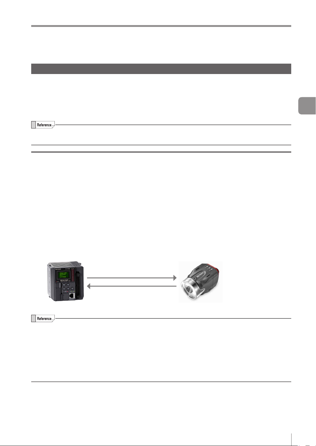
Vision Sensor
Getting Started
1
EtherNet/IP
2
Cyclic communication
3
PROFINET
4
256GB
IV Series
User’s Manual
(Field Network)
Read this manual before use.
After you read this manual, keep it in a safe place for future
reference.
Data I/O communication
5
Reference program
A
Page 2
Introduction
Introduction
Read this manual before using the product in order to achieve maximum performance.
Keep this manual in a safe place after reading it so that it can be used at any time.
Symbols
The following symbols alert you to important messages.
Be sure to read these messages carefully.
It indicates a hazardous situation which, if not avoided, will result
in death or serious injury.
It indicates a hazardous situation which, if not avoided, could
result in death or serious injury.
It indicates a hazardous situation which, if not avoided, could
result in minor or moderate injury.
It indicates a situation which, if not avoided, could result in
product damage as well as property damage.
It indicates cautions and limitations that must be followed during operation.
It indicates additional information on proper operation.
It indicates tips for better understanding or useful information.
It indicates the reference pages in this manual or the reference pages in separate manuals.
Cautions
(1) Unauthorized reproduction of this manual in whole or part is prohibited.
(2) The contents of this manual may be changed for improvements without prior notice.
(3) An utmost effort has been made to ensure the contents of this manual are as complete as possible. If
there are any mistakes or questions, please contact a KEYENCE ofce listed in the back of the manual.
(4) Regardless of item (3), KEYENCE will not be liable for any effect resulting from the use of this unit.
(5) Any manuals with missing pages or other paging faults will be replaced.
The company names and product names used in this manual are registered trademarks or the trademarks
of their respective companies.
Page 3
Safety Information for IV Series
Safety Information for IV Series
General Precautions
Do not use this product for the purpose to protect a human body or a part of human body.
This product is not intended for use as an explosion-proof product. Do not use this product in
hazardous location and/or potentially explosive atmosphere.
You must verify that the IV Series are operating correctly in terms of functionality and
performance before the start and the operation of the IV Series.
We recommend that you take substantial safety measures to avoid any damage in the event of
a problem occurring.
KEYENCE never warrants the function or performance of the IV Series if it is used in manner
that differs from the IV Series specications contained in this instruction manual or if the IV
Series are modied by yourself.
When the IV Series is used in combination with other instruments, functions and performance
may be degraded, depending on operating conditions and the surrounding environment.
Do not place the instruments, including peripherals, under the rapid temperature change. It
may cause condensation and may damage instruments or peripherals.
Remove the power cable from the power supply if you do not use this product for a long time.
Safety precautions on LED product
Use of controls or adjustments or performance of procedures other than those specied herein
may result in hazardous radiation exposure. Follow the instructions mentioned in this manual.
Otherwise, injury to the human body (eyes and skin) may result.
Do not stare into the direct or specularly reected beam.
Do not disassemble this product. The laser radiation emission from this product is not
automatically stopped when it is disassembled.
Do not direct the beam at people or into areas where people might be present.
Be careful of the path of the LED beam. If there is a possibility that the operator may be
exposed to the specular or diffuse reections, block the beam by installing a protective
enclosure.
Install this product so that the path of the LED beam is not as the same height as that of human
eye.
256GB
1
Page 4

Important Instructions
Important Instructions
Observe the following precautions to prevent malfunction of the IV Series and to
ensure that it is used properly.
Precautions on use
The power of this product and instruments connected to this product must be turned off when
the cable is to be installed or removed. Failure to do so may cause an electric shock or a
product damage.
Use this product in the correct supply voltage. Failure to do so may cause a product damage.
For instructions
Do not turn OFF the power while setting the items or saving the settings. Otherwise, all or
part of the setting data may be lost.
Do not let water, dust or oil stick to the camera/light of the sensor. Failure to do so may cause
a malfunction.
When this product becomes dirty, do not rub it with a wet cloth, benzene, thinner, or alcohol.
Doing so may change the color or shape of the unit.
If the unit is heavily contaminated, disconnect all the cables including the power supply cable,
wipe off the dirt with a cloth soaked with mild detergent, and then wipe with a soft dry cloth.
For external master image registration
If the external master image registration is to be performed frequently, set [Write ROM when
using Ext. Master Save] of the input option to [No] for nonvolatile memory protection of the
internal sensor. When the option is set to [Yes], the nonvolatile memory is guaranteed to write
for 100,000 times.
For automatic focus function
Automatic focus function is used for adjusting the focusing position at the time of installation.
This will not activate during the operation.
Focusing position can be registered in each program. The program congurations are
guaranteed to switch for 100,000 times. If the focusing position does not need to change for
each program, set [Auto Focus Adjustment Position] to [Common] for extending the life-span.
Do not apply shock or vibration during the focusing position adjustment. Failure to do so may
cause a product damage.
Measures to be taken when an abnormality occurs
In the following cases, turn the power OFF immediately. Using the IV Series in an abnormal
condition could cause re, electric shock, or malfunction.
Contact our ofce for repair.
If water or debris enters the IV Series.
If the IV Series is dropped or the case is damaged.
If abnormal smoke or odor emanates from the IV Series.
2
- IV Series User’s Manual (Field Network) -
Page 5

Important Instructions
Precautions on installation
To use this product correctly and safely, avoid installing it in the following locations. Failure to
do so may cause re, electric shock, or malfunction.
Outdoors
Altitude above 2000 m
Locations that are humid, dusty or poorly ventilated
Locations where the temperature is high such as those exposed to direct sunlight
Locations where there are ammable or corrosive gases
Locations where the unit may be directly subjected to vibration or impact
Locations where water, oil, or chemicals may splash onto the unit
To improve the anti-noise feature, install the unit following the precautions below. Otherwise, a
malfunction may occur.
Mount the sensor onto the insulated attached mounting adapter.
Ground the FG cable (drain cable) of the sensor.
Do not mount the unit in a cabinet where high-voltage equipment is already installed.
Mount the unit as far from power lines as possible.
Separate the unit as far as possible from the devices that emit strong electric or magnetic
eld (such as solenoid or chopper).
Separate the I/O signal line from the power line or high-voltage line.
For power supply
Noise superimposed on the power supply could cause malfunction. Use a stabilized DC
power supply congured with an isolation transformer.
When using a commercially available switching regulator, be sure to ground the frame ground
terminal.
Devices including this unit are precision components. Do not apply shock or vibration.
When connecting to a network, let engineers who are knowledgeable about networks handle it.
- IV Series User’s Manual (Field Network) -
3
Page 6

Precautions on Regulations and Standards
Precautions on Regulations and Standards
For IV-500C/IV-500CA/IV-500M/IV-500MA/IV-150M/IV-150MA/ IV-2000M/IV-2000MA
UL Certication
This product is a UL/C-UL Listed product.
UL File No. E301717
Category NRKH, NRKH7
Be sure to consider the following specications when using this product as a UL/C-UL Listed Product.
Use a power supply with Class 2 output dened in NFPA70 (NEC: National Electrical Code).
Power supply/ External input/ Control output shall be connected to a single Class 2 source only.
Use with an over current protection device which is rated 24 V or more and not more than 1A.
Enclosure Type 1 (Based on UL50)
CE Marking
Keyence Corporation has conrmed that this product complies with the essential requirements of
the applicable EC Directive, based on the following specications. Be sure to consider the following
specications when using this product in the Member State of European Union.
EMC Directive (2004/108/EC)
Applicable Standard EMI: EN60947-5-2, Class A
EMS: EN60947-5-2
The length of power I/O cable, Ethernet cable and Monitor cable must be less than or equal to 30m.
Remarks:
These specications do not give any guarantee that the end-product with this product incorporated
complies with the essential requirements of EMC Directive. The manufacturer of the end-product is solely
responsible for the compliance on the end-product itself according to EMC Directive.
Low-Voltage Directive (2006/95/EC)
Applicable Standard: EN62471
4
- IV Series User’s Manual (Field Network) -
Page 7

Version of the IV Series
Version of the IV Series
You can download the most recent operation software for the sensor (IV-150/500/2000) and IV-Navigator
(IV-H1) from the KEYENCE web site.
Please refer to the description on the homepage for the introduction method.
URL : http://www.keyence.com/
Operation software of the sensor (IV-150/500/2000)
Version Description
R1.00.00 The initial version.
R1.01.00 The processing time has been speeded up.
R1.10.00
R2.00.00
The processing time and the response time to program switching input have been
speeded up.
This is the version of this document.
The following functions have been added.
Logic output
Total status NG output
RUN output
FTP client function
Field network (EtherNet/IP, PROFINET)
Operation software of the monitor (IV-M30)
Version Description
R1.00.00 The initial version.
R1.01.01 Compatibility with Chinese (Simplied) / Chinese (Traditional).
R1.02.00 Compatibility with German.
R1.10.00 Compatibility with Tool Auto Tuning using a registration information le (*.ivt).
R2.00.00
This is the version of this document.
Compatibility with Italian / French / Spanish / Portuguese / Korean.
- IV Series User’s Manual (Field Network) -
5
Page 8

Version of the IV Series
IV-Navigator (IV-H1)
Version Description
R1.00.00 The initial version.
R1.01.00 Compatibility with German.
R1.02.00 Compatibility with Chinese (Simplied) / Chinese (Traditional).
The following functions have been added.
Addition of the IV-Simulator function
Addition of the image capture function to the operation of the [Save Image] button
R1.10.00
R2.00.00
Addition of the [Size] selection function to “Remove Outline”
Addition of the [Display Master Image] button to “Tool Auto Tuning”
Addition of the [Language] button (language selection) to the Activation Menu screen
This is the version of this document.
Compatibility with Italian / French / Spanish / Portuguese / Korean.
IVP-Convertor has been added.
6
- IV Series User’s Manual (Field Network) -
Page 9
Structure of This Manual
Structure of This Manual
1
2
3
4
5
A
Getting Started
EtherNet/IP
Cyclic communication
PROFINET
Data I/O communication
Reference program This chapter explains Reference program, etc.
This chapter explains the system congurations and
overview of IV Series.
This chapter describes the overview of EtherNet/IP and
the communication specications and functions of
the EtherNet/IP communication in the IV series.
This chapter describes the overview, setting method, data
allocation, and operating procedure of
the cyclic communication in the EtherNet/IP communication.
This chapter describes the overview of PROFINET and
the communication specications and functions of
the PROFINET communication in the IV series.
This chapter describes the overview, setting method, data
allocation, and operating procedure of
the data I/O communication in the PROFINET communication.
1
2
3
4
5
A
- IV Series User’s Manual (Field Network) -
7
Page 10

Contents
Contents
Introduction
Symbols
Cautions
Safety Information for IV Series..............................1
General Precautions ...........................................1
Safety precautions on LED product ....................1
Important Instructions .............................................2
Precautions on use .............................................2
Measures to be taken when an abnormality
occurs..................................................................2
Precautions on installation ..................................3
Precautions on Regulations and Standards ...........4
For IV-500C/IV-500CA/IV-500M/IV-500MA/
IV-150M/IV-150MA/IV-2000M/IV-2000MA ........... 4
UL Certication ................................................4
CE Marking ......................................................4
Version of the IV Series ..........................................5
Operation software of the sensor
(IV-150/500/2000) ...............................................5
Operation software of the monitor (IV-M30) ........5
IV-Navigator (IV-H1) ............................................ 6
Structure of This Manual ........................................7
Contents .................................................................8
Chapter 1 Getting Started
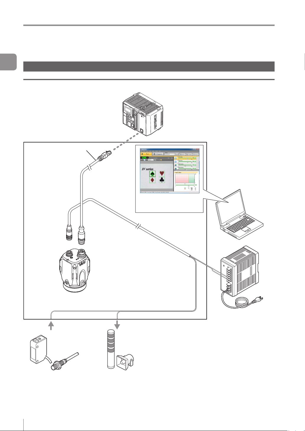
System Conguration ..........................................1-2
Basic congurations of IV-Series
Connecting the host device and
single sensor.................................................1-2
Connecting the host device and
multiple sensors
Overview of IV Series
IV Series...........................................................1-4
System conguration example......................1-4
Operation of the indicator light
............................................1-3
..........................................1-4
.....................1-2
......................1-5
Chapter 2 EtherNet/IP
Overview of EtherNet/IP ......................................2-2
What is EtherNet/IP?........................................2-2
EtherNet/IP communication specications and
functions in the IV series .....................................2-3
EtherNet/IP communication specications
in the IV series .................................................2-3
Overview of the Ethernet/IP
communications functions in the IV series .......2-3
List of supported PLCs .....................................2-4
Keyence PLC ................................................2-4
KV series ..............................................2-4
Rockwell Automation PLC ............................2-4
OMRON PLC ................................................2-4
Chapter 3 Cyclic communication
Overview of the cyclic communication.................3-2
What is cyclic communication? ........................3-2
Cyclic communication setting method .................3-3
Setting the IV series .........................................3-3
When settings on the monitor (IV-M30) ........3-3
When setting by IV-Navigator (IV-H1) ...........3-4
PLC settings .....................................................3-5
Establishing the connection ..........................3-5
Keyence KV series settings ..........................3-7
Rockwell Automation Control Logix series
settings
Data allocation in the cyclic communication
Input Assembly (IV series → PLC) .................3-10
Input Assembly parameter details ..................3-12
Output Assembly (PLC → IV series)
Output Assembly parameter details
Error code list
Warning code list ............................................3-23
Operating procedure of
the cyclic communication...................................3-26
Reading out the overall status result of
the IV series
(Handshake control [Disabled]) ......................3-26
Reading out the overall status result of
the IV series
(Handshake control [Enabled]).......................3-28
Switching the programs in the IV series
Registering a master image for
the IV series externally ...................................3-30
.........................................................3-8
Input Assembly Address 0:
Control result (response)
Input Assembly Address 1:
Control error result ..............................3-12
Input Assembly Address 2 to 3:
Handshake control/status/error result
Input Assembly Address 4 to 7:
Status result
Input Assembly Address 8 to 23:
Error/status/status result information
Input Assembly Address 24 to 51:
Statistics information
Input Assembly Address 52 to 71:
Position correction information ...........3-18
Input Assembly Address 72 to 391:
Tool information
Output Assembly Address 0 to 1:
Control request
Output Assembly Address 2 to 3:
Handshake control ..............................3-21
Output Assembly Address 4 to 11:
Program No. .......................................3-21
When a trigger is successful ...............3-26
When a trigger is unsuccessful ...........3-27
........................................3-15
..................................3-18
...................................3-20
.................................................3-22
....................3-12
...........................3-17
......3-10
...3-13
..3-16
..............3-19
...............3-20
.........3-29
8
- IV Series User’s Manual (Field Network) -
Page 11

Chapter 4 PROFINET
Overview of PROFINET ......................................4-2
What is PROFINET? ........................................4-2
PROFINET communication specications and
functions in the IV series .....................................4-3
IV series PROFINET communication
specications....................................................4-3
Specifying the IP address using
the DCP protocol ..............................................4-3
Overview of the PROFINET communication
functions in the IV series ..................................4-4
List of supported PLCs
Siemens PLC
Phoenix Contact PLC ...................................4-5
OMRON PLC ................................................4-5
.....................................4-5
................................................4-5
Chapter 5 Data I/O communication
Overview of the data I/O communication.............5-2
What is data I/O communication? ....................5-2
Data I/O communication setting method .............5-3
Setting the IV series .........................................5-3
When settings on the monitor (IV-M30) ........5-3
When setting by IV-Navigator (IV-H1) ...........5-4
Setting the device name...................................5-5
When settings on the monitor (IV-M30) ........5-5
When setting by IV-Navigator (IV-H1) ...........5-5
PLC settings .....................................................5-6
Establishing the data I/O communication .....5-6
Setting the Siemens TIA Portal .....................5-7
Setting the Siemens SIMATIC Manager .....5-11
Data allocations in
the data I/O communication...............................5-16
Control Modules (PLC → IV series) ...............5-16
Command Control ...............................5-16
Status Modules (IV series → PLC) ................5-17
Command Status Bits .........................5-17
Device Result Bits ...............................5-17
Device Status Words ..........................5-18
Device Statistics .................................5-18
Tool Result Modules (IV series→ PLC) ..........5-19
Position Adjust Result .........................5-19
Tool Result ..........................................5-19
Control Modules parameter details ................5-20
Command Control Address 0 to 1:
Control request ...................................5-20
Command Control Address 2 to 3:
Handshake control ..............................5-21
Command Control Address 4 to 11:
Program No. .......................................5-21
Status Modules parameter details..................5-22
Command Status Bits Address 0:
Control result (response) ....................5-22
Command Status Bits Address 1:
Control error result ..............................5-22
Command Status Bits Address 2 to 3:
Handshake control/status/error result
Device Results Bits Address 0 to 3:
Status result ........................................5-25
- IV Series User’s Manual (Field Network) -
...5-23
Contents
Device Status Words
Address 0 to 15:
Error/status/status result information
Device Statistics Address 0 to 27
(Statistics information) ........................5-27
Tool Result Modules parameter details ..........5-28
Position Adjust Result
Address 0 to 19
(Position correction information) .........5-28
Tool Result Address 0 to 19
(Tool information) ................................5-28
Error code list .................................................5-29
Warning code list ............................................5-30
Operating procedure of
the data I/O communication...............................5-32
Reading out the overall status result of
the IV series
(Handshake control [Disabled]) ......................5-32
When a trigger is successful ...............5-32
When a trigger is unsuccessful ...........5-33
Reading out the overall status result of
the IV series
(Handshake control [Enabled]).......................5-34
Switching the programs in the IV series .........5-35
Registering a master image for
the IV series externally ...................................5-36
...5-26
Appendices
Reference program (EtherNet/IP)....................... A-2
Handshake control [Disabled]
Keyence KV series ...................................... A-2
Description of the reference program
Rockwell Automation PLC
Description of the reference program
Handshake control [Enabled]
Keyence KV series ...................................... A-4
Description of the reference program
Rockwell Automation PLC ...........................A-5
Description of the reference program
Program switching........................................... A-6
Keyence KV series
Description of the reference program
Rockwell Automation PLC ...........................A-7
Description of the reference program
Reference program (PROFINET)
Index
Handshake control [Disabled] ......................... A-8
Siemens PLC ............................................... A-8
Description of the reference program
Handshake control [Enabled]
Siemens PLC
Description of the reference program
Program switching......................................... A-10
Siemens PLC
Description of the reference program
................................................................. A-12
...................................... A-6
............................................... A-9
............................................. A-10
......................... A-2
... A-2
........................... A-3
... A-3
.......................... A-4
... A-4
... A-5
... A-6
... A-7
....................... A-8
... A-8
.......................... A-9
... A-9
... A-10
9
Page 12

Contents
MEMO
10
- IV Series User’s Manual (Field Network) -
Page 13

1
Getting Started
This chapter explains the system congurations
and overview of IV Series.
System Conguration
Overview of IV Series ........................................1-4
.......................................1-2
1
Getting Started
- IV Series User’s Manual (Field Network) -
1-1
Page 14
System Conguration
System Conguration
1
Getting Started
Basic congurations of IV-Series
Connecting the host device and single sensor
IV Series
PLC or other host device
Ethernet cable
(2m/5m/10m)
In addition to the status result import,
the trigger control and switching
of the set program number can be
performed with the control output.
Setting support software
(IV-H1)
Sensor
IV-500C
IV-500CA
IV-500M
IV-500MA
IV-150M
IV-150MA
IV-2000M
IV-2000MA
Photoelectric/
proximity sensor etc.
Sends the signal to the
trigger input when the
target is detected.
Power I/O cable
(2m/5m/10m)
(Optional)
Dome attachment
IV-D10
Polarizing lter attachment
OP-87436/OP-87437
24 VDC power
Indicator light/buzzer
etc.
Alarm can be output
by the status output
function.
1-2
- IV Series User’s Manual (Field Network) -
Page 15
System Conguration
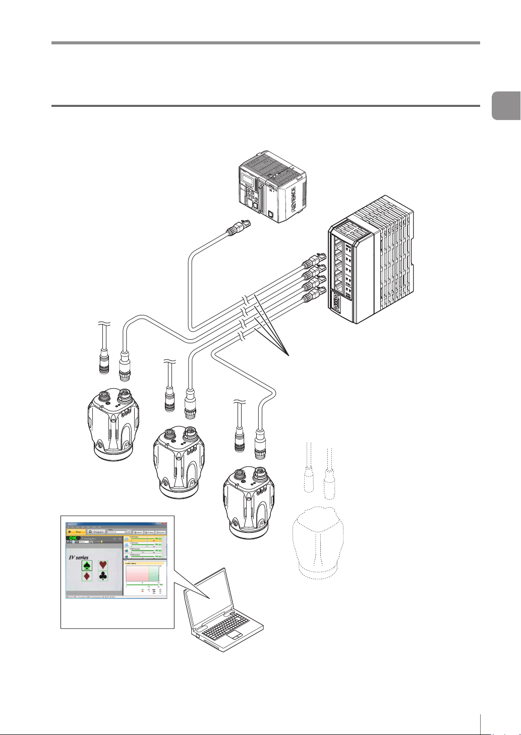
Connecting the host device and multiple sensors
PLC or other host device
Ethernet cable
(2m/5m/10m)
1
Getting Started
In addition to the status result import,
the trigger control and switching of the
set program number can be performed
with the control output.
Ethernet switch
Setting support software
(IV-H1)
- IV Series User’s Manual (Field Network) -
1-3
Page 16
Overview of IV Series
Overview of IV Series
1
Getting Started
IV Series
The IV Series is an all-in-one “Vision Sensor” featuring a camera, a light, and a controller. This sensor
can be attached easily so complicated detection operations such as detecting the shapes of parts with a
photoelectric switch can be achieved easily.
Operation conditions settings require the IV Software, IV-Navigator (IV-H1) or
the intelligent monitor (IV-M30). After setting is completed, the sensor can be operated independently.
The IV Series operates as an EtherNet/IP communication adaptor or a PROFINET communication I/O device.
With EtherNet/IP communication or PROFINET communication, the control output signal and status result,
etc., can be input to the PLC as communication data.
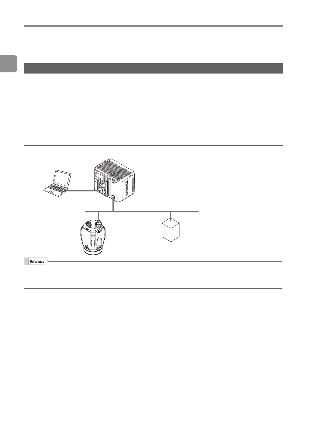
System conguration example
PLC or other host device
(EtherNet/IP communication scanner,
PROFINET communication I/O controller)
EtherNet/IP communication adapter,
PROFINET communication I/O device
Sensor (this unit)
EtherNet/IP communication and PROFINET communication cannot be used simultaneously.
For the details of installation, connection, and operation methods of the IV Series, refer to “IV Series
User’s Manual (Monitor/PC Software)”.
1-4
- IV Series User’s Manual (Field Network) -
Page 17

Overview of IV Series
Operation of the indicator light
Details on operations of the indicator light are
shown below.
4 5
1 2 3
1 PWR/ERR
Indicates the power supplying status to the
sensor and the error status of the sensor.
Green (ON)
Green (Blink)
Red (ON)
Red (Blink)
Orange (Blink)
(OFF)
2 OUT
Indicates the comprehensive result.
Green
.................. Comprehensive result is “NG”.
Red
(OFF)
Standby status until the rst
Orange (Blink)
...... Operating.
.... Setting processing. Operation
is stopped. Blinks once a
second.
.......... Unrecoverable error has
occurred.
....... Recoverable error has
occurred.
...
Flash LED has been required on
the PROFINET communication
I/O controller. Blinks 4 times
with a period of about a second.
............... Power is not supplied.
Adjusting the focusing position
(
manual focus only).
............... Comprehensive result is “OK”.
............... Setting processing.
judge nishes after starting the
operation or after switching
the program number.
...
Indicates the focusing status
while adjusting the focusing
position with the blinking speed
(manual focus type only).
Flash LED has been required on
the PROFINET communication
I/O controller. Blinks 4 times
with a period of about a second.
3 TRIG
Green light lights up (one-shot) according to
input of the internal or external trigger.
Orange (Blink)
4 STATUS
Indicates the connecting status to the PC.
Green (ON)
Green (Blink)
Red (Blink)
Red (ON)
............... IP address is not assigned.
(OFF)
Orange (Blink)
5 LINK/ACT
Indicates the linking status within PC or
Ethernet switch.
Green (ON)
Green (Blink)
...............
(OFF)
...
Flash LED has been required on
the PROFINET communication
I/O controller. Blinks 4 times
with a period of about a second.
......
Normally connected with monitor,
PC, EtherNet/IP communication
scanner, or PROFINET
communication I/O controller.
.... IP address has been retrieved
but the sensor is not correctly
connected with
EtherNet/IP communication
scanner, or PROFINET
communication I/O controller.
....... Timeout has occurred at the
communication with EtherNet/
IP communication scanner.
.......... IP address coincides with
another device.
Not correctly connecting with
PC.
..
Indicates the focusing status
while adjusting the focusing
position with the blinking speed
(manual focus type only).
...... Normally linked.
.... Normally linked, and the data
is sending/receiving.
Sensor is not normally linked.
monitor, PC,
1
Getting Started
- IV Series User’s Manual (Field Network) -
1-5
Page 18

Overview of IV Series
1
Getting Started
MEMO
1-6
- IV Series User’s Manual (Field Network) -
Page 19

2
EtherNet/IP
This chapter describes the overview of EtherNet/IP
and the communication specications and functions
of the EtherNet/IP communication in the IV series.
2
EtherNet/IP
Overview of EtherNet/IP
EtherNet/IP communication specications
and functions in the IV series...........................2-3
....................................2-2
- IV Series User’s Manual (Field Network) -
2-1
Page 20
Overview of EtherNet/IP
Overview of EtherNet/IP
EtherNet/IP is an open industrial networking standard developed and maintained by the ODVA (Open
2
DeviceNet Vendor Association, Inc.). All supported devices can use the communication network regardless
EtherNet/IP
of the vendor.
Ethernet and an industrial protocol have been combined and standardized as EtherNet/IP (Industrial Protocol).
Communication is achieved by combining a protocol called CIP (Common Industrial Protocol) and the TCP/
IP and Ethernet. This allows the network to be shared and used with standard Ethernet.
To start the Ethernet/IP communication, one device needs to open a communication line called a "connection"
for the other device. The device that will open a connection is referred to as the "scanner", and the device
whose connection will be opened is referred to as the "adapter" (IV series is an adapter device).
The EtherNet/IP communication offers the following two types of communications: Cyclic communication
for sending and receiving data periodically (Implicit communication), and message communication for
sending and receiving commands/responses at arbitrary timings.
In the cyclic communication, you can set the RPI (Request Packet Interval: communication cycle) based
on the priority of the data to be sent/received, enabling sending/receiving of data with adjusted overall
communication load. Various data including the control output, status result import, trigger control and
switching to the set program No. can be communicated without a ladder program.
In the message communication, you can send/receive the required commands and responses at the required
timings. The message communication is used for applications requiring no punctuality unlike the cyclic
communication, such as for reading and writing the adapter device settings.
What is EtherNet/IP?
The IV series supports cyclic communication (Implicit communication).
EtherNet/IP
communication
scanner
(Communication cycle: 5 ms)
High-speed
EtherNet/IP
communication
adapter
Low-speed (Communication cycle: 1000 ms)
Normal
(Communication
cycle: 100 ms)
EtherNet/IP
communication
adapter
EtherNet/IP
communication
adapter
2-2
- IV Series User’s Manual (Field Network) -
Page 21
EtherNet/IP communication specications and functions in the IV series
EtherNet/IP communication specications and
functions in the IV series
This section describes the overview of the EtherNet/IP communication functions supported in the IV series.
EtherNet/IP communication specications in the IV series
Cyclic communication
(Implicit messages)
Number of
connections
16
Overview of the Ethernet/IP communications functions in the IV series
The following shows the list of functions that can be used to control the IV series using the EtherNet/IP
communication.
Function Content
Trigger input Executes a trigger input for the sensor.
Program switching Executes a program switching for the sensor.
External master registration Executes an external master registration for the sensor.
Error clear input Executes an error clear.
Read out status Allows you to check the unit status (Imaging, RUN, BUSY, Error).
Read overall status result Reads out the overall status result.
Read judgment processing time Reads out the judgment processing time.
Read each tool’s status result Read each tool’s status result
Read statistics information
Reads out the number of triggers issued that generated a trigger
error and the number of trigger errors.
2
EtherNet/IP
If you are switching programs using the EtherNet/IP communication, set the [Switching method] option
to [Monitor/PC]. For details of the setting, refer to the “IV Series User’s Manual (Monitor / PC Software)”.
If the master registration will be executed using the EtherNet/IP communication, set the [Write to ROM
at external master reg.] option to [No]. For details of the setting,refer to the “IV Series User’s Manual
(Monitor / PC Software)”.
- IV Series User’s Manual (Field Network) -
2-3
Page 22

EtherNet/IP communication specications and functions in the IV series
Check the instruction manual of each PLC for details of the setting methods.
2
EtherNet/IP
Keyence PLC
List of supported PLCs
KV series
PLC model
KV-3000 KV-EP21V Ver.2 or later
KV-5000 KV-EP21V Ver.2 or later
KV-5500
EtherNet/IP
communication unit
(Built-in port or KV-
EP21V)
Rockwell Automation PLC
PLC model
1756 ControlLogix
1769 CompactLogix
EtherNet/IP
communication unit
1756-ENBT
1756-EN2T
(Built in the unit)
OMRON PLC
PLC model
EtherNet/IP
communication unit
Firmware
version
Ver.2 or later
Firmware
version
Ver.13 or later
Ver.13 or later
Firmware
version
Software used
KV STUDIO Ver.6.0 or later
Software used
RSLogix5000 Ver.13 or later
Software used
Version of the
software used
Version of the
software used
Version of the
software used
-
SYSMAC CJ2
SYSMAC CJ1 CJ1W-EIP21 V1.0 or later
SYSMAC CS1 CJ1W-EIP21 V1.0 or later
2-4
(Built-in port or
CJ1W-EIP21)
- IV Series User’s Manual (Field Network) -
V1.0 or later
CX-One Ver.3.0 or later
Page 23

3
Cyclic
communication
This chapter describes the overview, setting
method, data allocation, and operating procedure
of the cyclic communication in the EtherNet/IP
communication.
3
Cyclic communication
Overview of the cyclic communication
Cyclic communication setting method ............3-3
Data allocation in the cyclic communication
Operating procedure of
the cyclic communication...............................3-26
...........3-2
...3-10
- IV Series User’s Manual (Field Network) -
3-1
Page 24
Overview of the cyclic communication
Overview of the cyclic communication
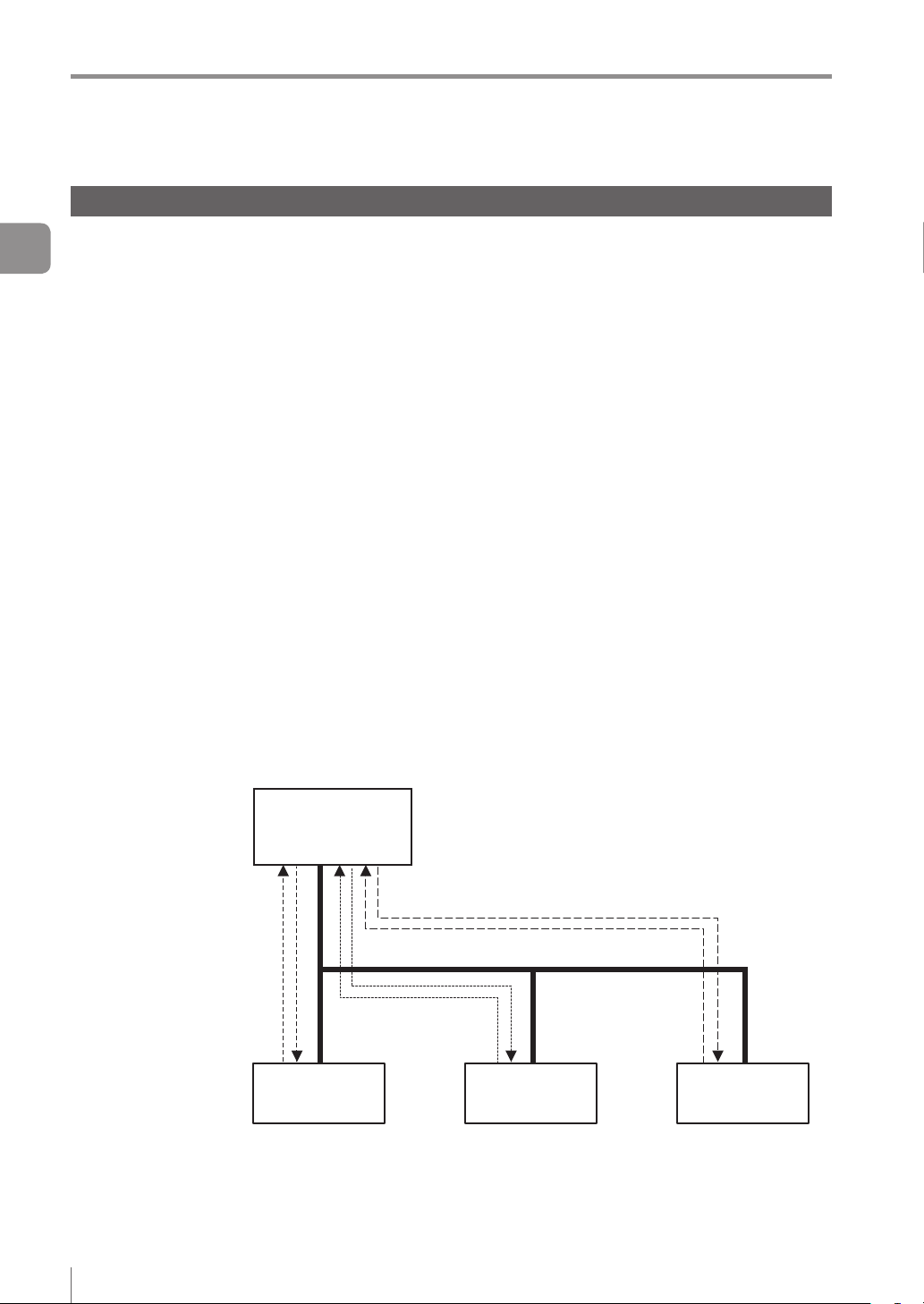
What is cyclic communication?
This function enables cyclic (i.e. in xed intervals) data communications with the EtherNet/IP devices.
This function provides high-speed control with several to several tens of milliseconds.
The communication can be controlled by referencing and updating the variables in the PLC, making it easy
3
to control the programs on the PLC side.
Cyclic communication
Input Area
Status result
Control/status/error result
Statistics information
Tool information
RPI
(Communication
Output Area
Trigger control
External master image
registration control
Program switching control
Handshake control
Communication settings for the cyclic communication, such as the RPI (communication cycle) and the
data size, will be congured on the PLC side.
In a network with many connected devices (including the EtherNet/IP devices), a network delay and/
or packet loss may occur when there is a heavy load on the network. Conduct a thorough verication
before the operation.
cycle)
Output data
Status result
Control/status/error result
Statistics information
Tool information
Input data
Trigger control
External master image
registration control
Program switching control
Handshake control
3-2
- IV Series User’s Manual (Field Network) -
Page 25
Cyclic communication setting method
Cyclic communication setting method
This following explains the setting method when
using the cyclic communication.
To control the IV series using the EtherNet/IP
communication, select [Network connection] for
the sensor connection setting. When connected
directly, the eld network settings will be greyed
out and disabled.
If you have modied the protocol settings, the
connection with the sensor will be terminated
and then restarted.
Setting the IV series
You can congure the following settings for the IV
series using the monitor (IV-M30) or IV-Navigator
(IV-H1).
When settings on the monitor (IV-M30)
Set the eld network settings of the sensor to
[EtherNet/IP].
Tap the [Sensor Advanced] button on the
1
Sensor Setup Menu screen.
Tap the [Settings] button in the “Field
3
Network”.
Select [Ethernet/IP] for the protocol.
4
To enable the handshake control, select
5
[Enable].
3
Cyclic communication
Tap the [Environmental] button, and then
2
the [Adv. Network Settings] button.
- IV Series User’s Manual (Field Network) -
When the protocol is set as [Disable],
this setting item is shaded and cannot be
selected.
When the data handshake control is set
as [Enabled], the status result will not be
updated until [Result acquisition complete
notice] (“Address2, Bit0” of Output Assembly)
is input.
“Operating procedure of the cyclic
communication” (Page 3-26)
After the setting is completed, tap the [OK]
6
button.
3-3
Page 26
Cyclic communication setting method
When setting by IV-Navigator (IV-H1)
Set the eld network settings of the sensor to
[EtherNet/IP].
Display the Advanced Sensor Settings
3
1
Cyclic communication
screen.
Select the [Environmental] tab, and then
2
click the [Setting] button under [Field
network].
Select [EtherNet/IP] in [Protocol] for the
3
eld network.
To enable the handshake control, check this
check box .
When the protocol is set as [Disable],
this setting item is shaded and cannot be
selected.
When the data handshake control is set as
[Enabled], the status result will not be updated
until [Result acquisition complete notice]
(“Address2, Bit0” Output Assembly) is input.
“Operating procedure of the cyclic
communication” (Page 3-26)
After the setting is completed, click the
4
[OK] button.
The system returns to the main screen in
[Program].
Click the [OK] button.
5
3-4
- IV Series User’s Manual (Field Network) -
Page 27
Cyclic communication setting method
PLC settings
You can set the following settings for the PLC:
(1)
Set the connection to be used for the cyclic communication.
(2)
Set the device to be used for the cyclic communication.
For details of the setting, refer to the instruction manual of each PLC.
If you are using the Keyence KV series, (1) and (2) can be set automatically simply by making a selection
in KV STUDIO.
Establishing the connection
In the cyclic communication, one device opens a logical communication circuit called a “connection” for the
other device; and data communication will become possible if the open is successful.
The device that will open a connection is referred to as the “scanner”, and the device whose connection
will be opened is referred to as the “adapter”.
(IV series is an adapter device)
In the EtherNet/IP communication, a connection must be opened from the scanner when the cyclic
communication is started.
3
Cyclic communication
The communication is started in the following procedure:
(1) The scanner requests a connection open request to the adapter.
(2) Compatibility will be checked on the adapter side.
(3) A connection will open if no error is encountered in the compatibility check.
(1) Connection open request
(2) Compatibility check
(3) Connection open
Scanner Adapter device
A compatibility check is used to check whether the device set by the scanner and the IV series are in
match with one another, in order to prevent the scanner from communicating with a wrong device when
it communicates with the IV series.
Communication settings for the cyclic communication, such as the communication cycle (RPI) and the
data size, will be congured on the scanner side.
In a network with many connected devices (including the EtherNet/IP devices), a network delay and/
or packet loss may occur when there is a heavy load on the network. Conduct a thorough verication
before the operation.
- IV Series User’s Manual (Field Network) -
3-5
Page 28
Cyclic communication setting method
There are many types of connections, and the connection available for each device are dened in the EDS
le.
The following shows the list of connections that are available in the IV series.
3
No Connection name Application type I/O
Cyclic communication
Monitor Data And
External Input
1
(Monitor/External
input)
Monitor Data (Input
2
Only)
(Monitor data)
When using the Keyence KV series (EtherNet/IP communication scanner), the names of the connections
with the IV series will be “Monitor/External Input” and “Monitor Data”. The relationship of each connection
name is as described below.
1 : Monitor Data And External Input → Monitor/External input
2 : Monitor Data (Input Only) → Monitor data
The trigger timings of each connection are controlled by the cyclic communications; and both the point-
to-point and Multicast connection types are supported.
If you wish to open “Exclusive Owner” and “Input Only” connections simultaneously, set the connection
type to “Multicast” and match the RPI and the size.
The details of each application type are as described below.
[Exclusive Owner]
This connection allows you to congure the data transmission from the scanner to the IV series, and
vice versa.
This connection type is used when the scanner will not only monitor the data of the IV series but also
provide external input to the IV series.
It is not possible for multiple scanners to open "Exclusive Owner" connections for a single IV series
unit.
[Input Only]
This connection only allows you to congure the data transmission from the IV series to the scanner.
This connection is used when the scanner will only monitor the data of the IV series.
Multiple scanners can simultaneously open “Input Only” connections for a single IV series unit.
If connections will be opened simultaneously from multiple scanners, set the connection type to
“Multicast” and match the RPI and the size.
Exclusive Owner
Input Only
This unit
→ Scanner
Scanner
→ This unit
This unit
→ Scanner
Scanner
→ This unit
Assembly
Instance
64H (100) 2 to 392
65H (101) 2 to 12
64H (100) 2 to 392
FEH (254) 0
Size
(bytes)
RPI
5 to 10000ms
5 to 10000ms
3-6
- IV Series User’s Manual (Field Network) -
Page 29
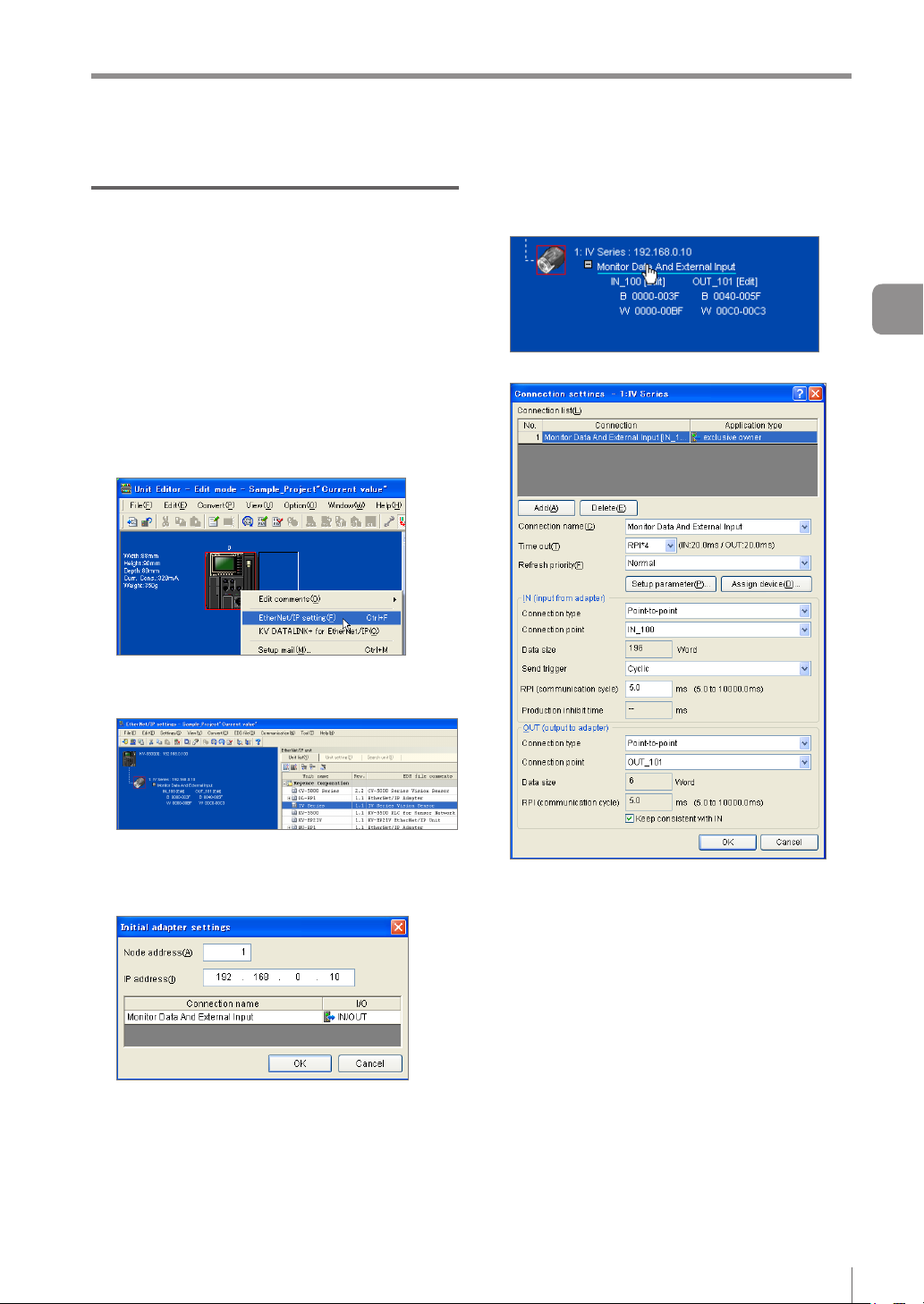
Keyence KV series settings
This following explains the setting method when
using KV-5500.
For details of the required setting, such as the unit
conguration for the PLC and the KV STUDIO
settings for connecting with the PC, refer to the “KV
STUDIO User’s Manual” and the “KV-EP21V User’s
Manual”.
Right-click KV-5500 in the unit editor of
1
KV STUDIO, and then select [EtherNet/IP
setting].
Cyclic communication setting method
Modify the settings as necessary.
4
Click the connection name in the scan list.
The [Connection settings] screen will appear.
3
Cyclic communication
Drag [IV Series] from the Unit list and add
2
it to the scan list.
Set the Node address and IP address
3
for the IV series on the [Initial adapter
settings] screen.
Connection name
Select [Monitor/External input] or [Monitor data].
RPI (communication cycle)
You can set the cyclic communication cycle.
Connection type
Select [Point-to-point] or [Multicast].
Save the settings and close [EtherNet/IP
5
settings] and the unit editor.
- IV Series User’s Manual (Field Network) -
3-7
Page 30
Cyclic communication setting method
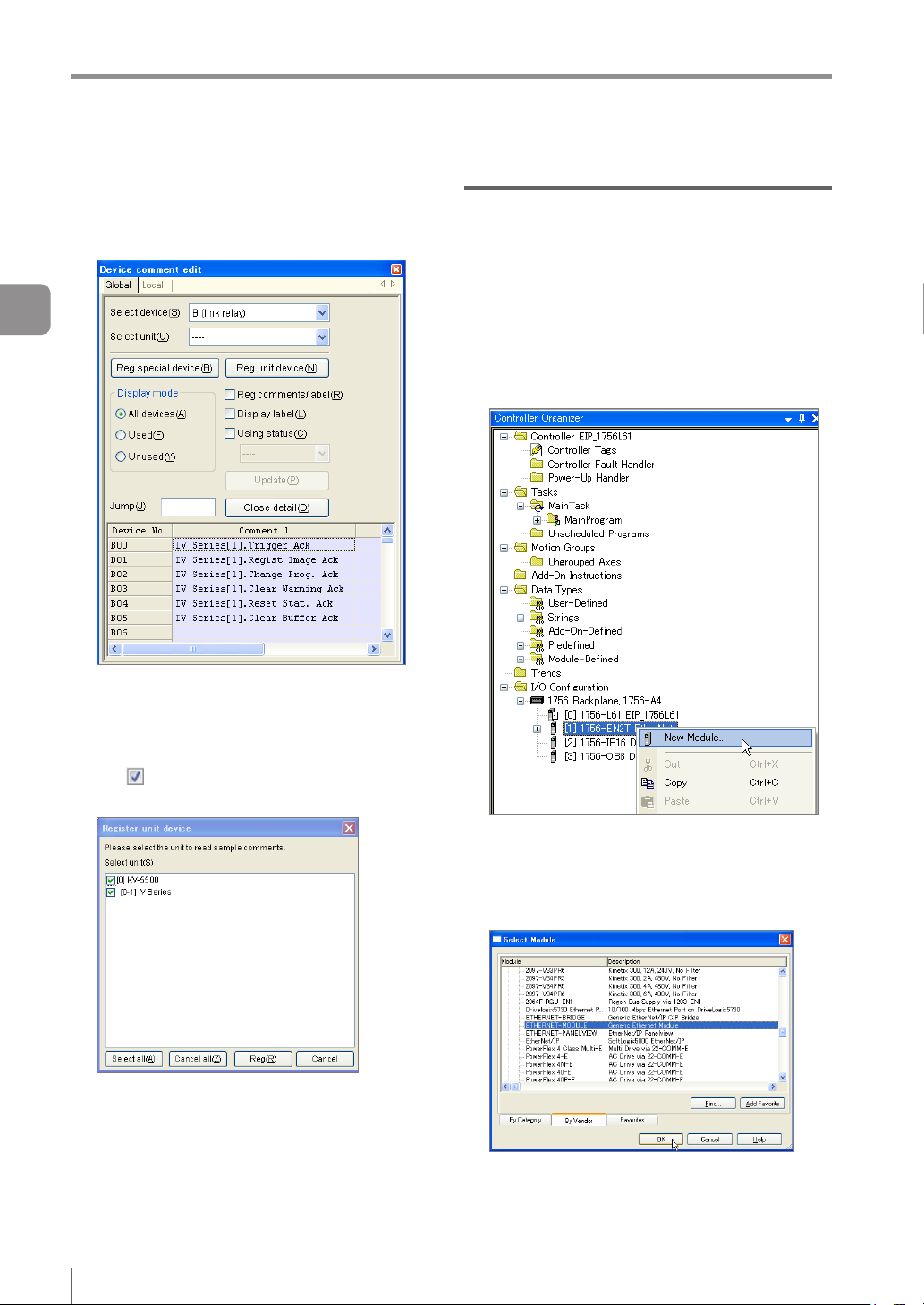
Select [Device comment edit window]
6
from the [Edit] menu in KV STUDIO.
The [Device comment edit] screen will appear.
Rockwell Automation Control Logix series settings
This following explains the setting method when
using a Control Logix PLC.
3
Cyclic communication
Click [Details].
The [Register unit device] screen will appear.
Make sure that the [IV Series] checkbox is
7
ON
in the [Select unit] eld, and then
click the [Reg] button.
Select the EtherNet/IP communication unit
1
to be connected with the IV series in
the I/O conguration of RsLogix5000, and
then right-click to select [New Module].
The [Select Module] screen will appear.
Select [PLC Transfer] from the [Monitor/
8
Simulator] menu of KV STUDIO.
3-8
- IV Series User’s Manual (Field Network) -
Click the [+] button next to Communications,
2
and then select EtherNET-MODULE (Generic
Ethernet Module) and click the [OK] button.
The [New Module] screen will appear.
Page 31

Modify the settings as necessary.
3
Name (Device name)
You can assign a desired name. The following
tags will be generated based on the entered
names and used for the data sent and received
in the cyclic communication.
(Device name): I
(Device name): O
(Device name): C
Comm Format
You can enter a desired format. Due to the
structure of the assembly object, programming
will be easier with a format that supports a
2-byte alignment.
IP Address
You can enter the IP address of the IV series.
Input (Assembly Instance)
Enter “100”.
Input (Size)
You can enter the Input Assembly size of the IV
series.
Output (Assembly Instance)
Enter “101”.
Output (Size)
You can enter the Output Assembly size for the
IV series.
Conguration (Assembly Instance)
Enter “1”.
Conguration Size
Enter “0”.
..... Information received from
the IV series
... Information to be sent to
the IV series
... Not used.
Cyclic communication setting method
Setting the Comm Format option to [Input
Data] will enable you to establish cyclic
communication with multiple PLCs using the
“Input only” connection.
To set the Comm Format to [Input Data],
perform the following settings on each PLC.
Item Setting contents
Comm Format Input Data-INT
Input
(Assembly Instance)
Input (Size)
Output
(Assembly Instance)
Output (Size)
If communications with multiple PLCs
will be established using the “Input Only”
connection, set the connection type to
“Multicast”.
For details of the Input Assembly and Output
Assembly sizes for the IV Series, refer to
“EtherNet/IP communication specications in
the IV series” (Page 2-3) .
Set the RPI (communication cycle) for the
4
cyclic communication.
Make sure to set a value longer than or equal to 5 ms.
Download the settings to the PLC.
5
The EtherNet/IP communication will be enabled
when you switch to online after downloading the
settings.
100
Input Assembly size
of the IV series
254
Output Assembly size
for the IV series
3
Cyclic communication
- IV Series User’s Manual (Field Network) -
3-9
Page 32

Data allocation in the cyclic communication
Data allocation in the cyclic communication
Input Assembly (IV series → PLC)
Input Assembly are devices that write responses from the IV series to the PLC.
The device map of the data allocated for the Input Assembly is as shown below.
These parameters output the statuses, status results and statistics information of the IV series.
3
For details of each parameter, refer to “Input Assembly parameter details” (Page 3-12).
Cyclic communication
Address Bit7 Bit6 Bit5 Bit4 Bit3 Bit2 Bit1 Bit0
0 Reserved by system
1 Reserved by system
2 Reserved by system
3
Error Warning
4 Reserved by system
5 Reserved by system
Tool 8 Tool 7 Tool 6 Tool 5 Tool 4 Tool 3 Tool 2 Tool 1
6
7
Tool 16 Tool 15 Tool 14 Tool 13 Tool 12 Tool 11 Tool 10 Tool 9
8 - 9
10 - 11
12 - 13
14 - 15
16 - 17
18 - 19
20 - 21
22 - 23
24 - 25
26 - 27
28 - 29
30 - 31
32 - 35
36 - 39
40 - 43
44 - 47
48 - 51
52 - 53
Buffer
clear
response
Ready RUN
Buffer
overrun
LOGIC4 LOGIC3 LOGIC2 LOGIC1
Number of remaining buffers (Unsigned 16-bit integer)
Current program No. (Unsigned 16-bit integer)
Program No. during judgment (Unsigned 16-bit integer)
Processing time (Unsigned 16-bit integer)
Processing time MAX (16-bit unsigned integer)
Processing time MIN (Unsigned 16-bit integer)
Processing time AVE (Unsigned 16-bit integer)
Number of triggers (Unsigned 32-bit integer)
Number of OKs (Unsigned 32-bit integer)
Number of NGs (Unsigned 32-bit integer)
Number of trigger errors (Unsigned 32-bit integer)
Position correction score (Unsigned 16-bit integer)
Statistics
reset
response
Error NO. (Unsigned 16-bit integer)
Warning No. (Unsigned 16-bit integer)
Checksum (Unsigned 16-bit integer)
Result NO. (Unsigned 16-bit integer)
Reserved by system
Reserved by system
Warning
clear
response
Imaging
status
Reserved by system
Program
switching
response
Program
switching
failed
BUSY
Master
registration
response
Master
registration
failed
Result
update
complete
Position
correction
Trigger
response
Trigger
failed
Result
available
Overall
judgment
3-10
- IV Series User’s Manual (Field Network) -
Page 33

Data allocation in the cyclic communication
Address Bit7 Bit6 Bit5 Bit4 Bit3 Bit2 Bit1 Bit0
54 - 55
56 - 57
58 - 59
60 - 71
72 - 73
74 - 75
76 - 77
78 - 79
80 - 81
82 - 91
92 - 391
Position correction score MAX (Unsigned 16-bit integer)
Position correction score MIN (Unsigned 16-bit integer)
Position correction score Lower threshold (Unsigned 16-bit integer)
Reserved by system
Tool 1 score (Unsigned 16-bit integer)
Tool 1 score MAX (Unsigned 16-bit integer)
Tool 1 score MIN (Unsigned 16-bit integer)
Tool 1 lower threshold (Unsigned 16-bit integer)
Tool 1 upper threshold (Unsigned 16-bit integer)
Reserved by system
Tool 2 to 16 (Same as Tool 1)
The start address of tool number “n” is 72 + (n-1) x 20
3
Cyclic communication
- IV Series User’s Manual (Field Network) -
3-11
Page 34

Data allocation in the cyclic communication
Input Assembly parameter details
Input Assembly Address 0: Control result (response)
The Bits at Address 0 of the Input Assembly have the following functions:
3
Cyclic communication
Address Bit Item Content Data content
0
Input Assembly Address 1: Control error result
The Bits at Address 1 of the Input Assembly have the following functions:
Address Bit Item Content Data content
1
0 Trigger response
Master image registration
1
response
Program switching
2
response
3 Warning clear response
4 Statistics reset response
5 Buffer clear response Stores the buffer clear response.
6 to 7 Reserved by system --- ---
0 Trigger failed
Master image registration
1
failed
2 Program switching failed
3 to 7 Reserved by system --- ---
Stores the external trigger
response.
Stores the master image
registration response.
Stores the program switching
response.
Stores the warning clear
response.
Stores the statistics reset
response.
This bit is output when the
external trigger is unsuccessful.
This bit is output when the
master image registration is
unsuccessful.
This bit is output when
the program switching is
unsuccessful.
0 : OFF
1 : ON
0 : OFF
1 : ON
0 : OFF
1 : ON
0 : OFF
1 : ON
0 : OFF
1 : ON
0 : OFF
1 : ON
0 : 1 : The external trigger
0 : 1 :
0 : 1 : Program switching
has failed.
Master image
registration has failed.
has failed.
3-12
- IV Series User’s Manual (Field Network) -
Page 35

Data allocation in the cyclic communication
Input Assembly Address 2 to 3: Handshake control/status/error result
The Bits at Address 2 to 3 of the Input Assembly have the following functions:
Address Bit Item Content Data content
0 : The status
0 Result available
1 Result update complete
2 BUSY
2
3 Imaging
4 RUN
5 Ready
6 to 7 Reserved by system --- ---
0 to 4 Reserved by system --- ---
5 Buffer overrun status
3
6 Warning status
7 Error status
This bit is output when the
status result can be acquired.
This bit switches the ON/OFF
statuses when the status result
is updated.
This bit is output when the unit
is unable to accept new trigger
inputs, such as while performing
imaging, processing a judgment,
registering an external master
image, switching programs, etc.
This bit is output while the unit
is performing imaging operation.
This bit is output when the unit
is “RUN” and no system errors
have occurred.
This bit is output when the
start-up sequence of this unit
completes after power-on.
If handshake control is
[Enabled], this bit is output when
an overrun of the status result
has occurred.
This bit outputs the warning
status of the unit.
This bit outputs the error status
of the unit.
result cannot be
acquired.
1 : The status result
can be acquired.
0 <=> 1:
The statuses will
be switched when
the status result is
updated.
0 : The unit is not in
busy status.
1 : The unit is in busy
status.
0 : The unit is not
performing imaging
operation.
1 : The unit is
performing imaging.
0 : The unit is not in
operation.
1 : The unit is
operating normally.
0 : The start-up has
not completed yet.
1 : The start-up has
completed.
0
: No buffer overrun
has occurred.
1 : The buffer is in
overrun status.
0 : The unit is not in
warning status.
1 : The unit is in
warning status.
0 : The unit is not in
error status.
1 : The unit is in error
status.
3
Cyclic communication
- IV Series User’s Manual (Field Network) -
3-13
Page 36

Data allocation in the cyclic communication
By monitoring whether the unit is in “Imaging” status, you can determine whether the target object or
the unit can be moved before completion of the image processing.
“BUSY” and “Imaging” statuses may be skipped in some cyclic frequency settings. It is therefore
necessary to take the imaging condition into consideration when setting the cyclic frequency.
3
Cyclic communication
Warning statuses can be cleared from the EtherNet/IP communication. For the warning details, refer to
the warning code. The rst occurred warning code will be displayed.
When two or more warnings are issued, all subsequent warnings after the rst warning will be saved in
the history. If you clear the warnings, the warning code of the highest priority warning will be displayed.
Warning
Warning clear
Warning No.
Error statuses cannot be cleared from the EtherNet/IP communication. For the error details, refer to the
Warning code 1 00 Warning code 2
error code. The error code of the highest priority error will be displayed.
The buffer overrun status can be cleared using a warning clear.
3-14
- IV Series User’s Manual (Field Network) -
Page 37

Data allocation in the cyclic communication
Input Assembly Address 4 to 7: Status result
The Bits at Address 4 to 7 of the Input Assembly have the following functions:
Address Bit Item Content Data content
0 Overall judgment
1 Position correction
4
5 0 to 7 Reserved by system --- ---
6
7
2 Logic 1 Displays the result of Logic 1. 0 : NG 1 : OK
3 Logic 2 Displays the result of Logic 2. 0 : NG 1 : OK
4 Logic 3 Displays the result of Logic 3. 0 : NG 1 : OK
5 Logic 4 Displays the result of Logic 4. 0 : NG 1 : OK
6 to 7 Reserved by system --- ---
0 Tool 1 Displays the result of Tool 1. 0 : NG 1 : OK
1 Tool 2 Displays the result of Tool 2. 0 : NG 1 : OK
2 Tool 3 Displays the result of Tool 3. 0 : NG 1 : OK
3 Tool 4 Displays the result of Tool 4. 0 : NG 1 : OK
4 Tool 5 Displays the result of Tool 5. 0 : NG 1 : OK
5 Tool 6 Displays the result of Tool 6. 0 : NG 1 : OK
6 Tool 7 Displays the result of Tool 7. 0 : NG 1 : OK
7 Tool 8 Displays the result of Tool 8. 0 : NG 1 : OK
0 Tool 9 Displays the result of Tool 9. 0 : NG 1 : OK
1 Tool 10 Displays the result of Tool 10. 0 : NG 1 : OK
2 Tool 11 Displays the result of Tool 11. 0 : NG 1 : OK
3 Tool 12 Displays the result of Tool 12. 0 : NG 1 : OK
4 Tool 13 Displays the result of Tool 13. 0 : NG 1 : OK
5 Tool 14 Displays the result of Tool 14. 0 : NG 1 : OK
6 Tool 15 Displays the result of Tool 15. 0 : NG 1 : OK
7 Tool 16 Displays the result of Tool 16. 0 : NG 1 : OK
Displays the overall status
result.
Displays the position correction
result.
0 : NG 1 : OK
0 : NG 1 : OK
3
Cyclic communication
If the position correction/logic/tool is not set, the data content will be “0”.
If the status result of the tool is either “trigger standby” (no judgment) or “judgment not possible”, the
data content will be OFF (0).
- IV Series User’s Manual (Field Network) -
3-15
Page 38

Data allocation in the cyclic communication
Input Assembly Address 8 to 23: Error/status/status result information
z
The Bits at Address 8 to 23 of the Input Assembly have the following functions:
Address
3
Cyclic communication
8 to 9 UINT Error code
10 to 11 UINT Warning code
12 to 13 UINT
14 to 15 UINT Checksum
16 to 17 UINT Current program No.
18 to 19 UINT
20 to 21 UINT Result No.
22 to 23 UINT Processing time
* UINT : Unsigned 16-bit integer
UDINT : Unsigned 32-bit integer
Data
type*
Item Content Data content
Number of remaining
buffers
Program No. during
judgment
Displays the currently occurring
error code.
Displays the currently occurring
warning code.
Displays the number of status
results that can be buffered, if
handshake control is [Enabled].
Displays the current sensor
setting status using an arbitrary
5-digit integer.
Displays the current program
No.
Displays the program No. of the
latest judgment process.
Displays the judgment process
counts.
Displays the processing time of
the latest judgment process.
0 to 128
0 to 128
0 to 10
0 to 65535
0 to 31
0 to 31
0 to 32767
0 to 10000
yThe unit of processing time is msec.
yIf two or more errors are occurring at the same time, the error code of the highest priority error will be
displayed.
“Error code list” (Page 3-22)
yThe rst occurred warning code will be displayed.
“Warning code list” (Page 3-23)
yA checksum can be used to monitor whether the sensor settings have been modied by a third party.
yThe checksum will remain unchanged even if you switch programs.
yThe checksum will remain unchanged even if you change the IP address, subnet mask, default gateway
or port number of the IV series.
yFor the number of remaining buffers, refer to “Reading out the overall status result of the IV series
(Handshake control [Enabled])” (Page 3-28).
yThe upper limit value of the result No. is 32767. If the maximum value is exceeded, it will go back to 0
and start counting up again.
yThe result No. will also count the judgment process counts that were skipped due to the cyclic
frequency setting.
3-16
- IV Series User’s Manual (Field Network) -
Page 39

Data allocation in the cyclic communication
Input Assembly Address 24 to 51: Statistics information
The Bits at Address 24 to 51 of the Input Assembly have the following functions:
Address
24 to 25 UINT Processing time MAX
26 to 27 UINT Processing time MIN
28 to 29 UINT Processing time AVE
30 to 31 --- Reserved by system --- ---
32 to 35 UDINT Number of triggers
36 to 39 UDINT Number of OKs
40 to 43 UDINT Number of NGs
44 to 47 UDINT Number of trigger errors
48 to 51 --- Reserved by system --- ---
* UINT : Unsigned 16-bit integer
UDINT : Unsigned 32-bit integer
Data
type*
Item Content Data content
Displays the maximum
processing time value.
Displays the minimum
processing time value.
Displays the average processing
time value.
Displays the total number of
triggers issued.
Displays the total number of
triggers issued whose overall
status result was “OK”.
Displays the total number of
triggers issued whose overall
status result was “NG”.
Number of triggers issued that
generated a trigger error
0 to 10000
0 to 10000
0 to 10000
0-999999999
0-999999999
0-999999999
0-999999999
3
Cyclic communication
The unit of processing time is msec.
The maximum number of triggers is 999999999. If the maximum value is exceeded, it will go back to 0
and start counting up again.
The maximum value for the number of OK triggers, number of NG triggers, and the number of trigger
errors is 999999999. The value will stop updating when the upper limit value is reached.
A reset will occur in the following conditions:
When [Statistics reset] is input
When a tool is added/deleted/copied
When the enable/disable status of the upper threshold value for the color area/area tool or the setting
scale has been changed via user operation or tool auto-tuning
When a tool auto-tuning is started with two or more tools other than the position correction tool set
When the sensor is switched OFF
When the program is switched
When a correction for the sensor is started
When the sensor is initialized
- IV Series User’s Manual (Field Network) -
3-17
Page 40

Data allocation in the cyclic communication
Input Assembly Address 52 to 71: Position correction information
The Bits at Address 52 to 71 of the Input Assembly have the following functions:
Address
3
Cyclic communication
52 to 53 UINT
54 to 55 UINT
56 to 57 UINT
58 to 59 UINT
60 to 71 --- Reserved by system --- ---
* UINT : Unsigned 16-bit integer
UDINT : Unsigned 32-bit integer
Data
type*
Item Content Data content
Position correction tool
matching rate
Position correction tool
matching rate MAX
Position correction tool
matching rate MIN
Position correction tool
threshold
Stores the matching rate of the
position correction tool.
Stores the maximum matching
rate value of the position
correction tool.
Stores the minimum matching
rate value of the position
correction tool.
Stores the threshold value of the
position correction tool.
0 to 100
0 to 100
0 to 100
0 to 100
Maximum and minimum matching rate values of the position correction tool will be reset in the same
manner as the statistics information.
If the position correction tool is not set, the data content will be “0”.
Input Assembly Address 72 to 391: Tool information
The Bits at Address 72 to 391 of the Input Assembly have the following functions:
Address
72 to 73 UINT Tool 1 matching rate
74 to 75 UINT
76 to 77 UINT Tool 1 matching rate MIN
78 to 79 UINT Tool 1 lower limit value
80 to 81 UINT Tool 1 upper limit value
82 to 91 --- Reserved by system --- ---
Thereafter, the information of tool 2, 3, ... 16 will be assigned for each 20-byte Address of Input Assembly.
* UINT : Unsigned 16-bit integer
UDINT : Unsigned 32-bit integer
Data
type*
Item Content Data content
Tool 1 matching rate MAX
Stores the matching rate of Tool
1.
Stores the maximum matching
rate value of Tool 1.
Stores the minimum matching
rate value of Tool 1.
Stores the lower threshold value
of Tool 1.
Stores the upper threshold
value of Tool 1.
0 to 999
0 to 999
0 to 999
0 to 999
0 to 999
Maximum and minimum matching rate values of the tool will be reset in the same manner as the
statistics information.
If the tool is not set, the data content will be “0”.
If the upper threshold value of the tool is not set, the data content of the tool’s upper limit value will be
“65535”.
3-18
- IV Series User’s Manual (Field Network) -
Page 41

Data allocation in the cyclic communication
Output Assembly (PLC → IV series)
Output Assembly are devices that write instructions from the PLC to the IV series.
The device map of the data allocated for the Output Assembly is as shown below.
These parameters are responsible for the control instructions for the IV series, clearing of warnings and
handshake control.
For details of each parameter, refer to “Output Assembly parameter details” (Page 3-20).
Address Bit7 Bit6 Bit5 Bit4 Bit3 Bit2 Bit1 Bit0
0 Reserved by system
1 Reserved by system
2 Reserved by system
3 Reserved by system
4 - 5 Program No.
6 - 11 Reserved by system
Buffer
clear
request
Statistics
reset
request
Warning
clear
request
Program
switching
request
Master
registration
request
Trigger
request
Result
acquisition
complete
notication
3
Cyclic communication
- IV Series User’s Manual (Field Network) -
3-19
Page 42

Data allocation in the cyclic communication
Output Assembly parameter details
Output Assembly Address 0 to 1: Control request
The Bits at Address 0 to 1 of the Output Assembly have the following functions:
3
Cyclic communication
Address Bit Item Content Data content
0
1 0 to 7 Reserved by system --- ---
The following will occur when a buffer clear is requested:
If handshake control is [Enabled]
The current status result will be cleared.
The status result in the buffer will be cleared.
The result available bit will become OFF (0).
The number of remaining buffers will become “10”.
If the handshake control is [Disabled]
The current status result will be cleared.
The result available bit will become OFF (0).
If you are switching programs using the EtherNet/IP communication, set the [Switching method] option
to [Monitor/PC]. For details of the setting, refer to the “IV Series User’s Manual (Monitor / PC Software)”.
Buffer overrun and warning statuses will not be cleared even if you execute a buffer clear request.
0 Trigger request Requests the external trigger. 0 : OFF 1 : ON
Master image registration
1
request
Program switching
2
request
3 Warning clear request Requests a warning clear. 0 : OFF 1 : ON
4 Statistics reset request Requests a statistics reset. 0 : OFF 1 : ON
5 Buffer clear request Requests a buffer clear. 0 : OFF 1 : ON
6 to 7 Reserved by system --- ---
Requests a master image
registration.
Requests a program switching. 0 : OFF 1 : ON
0 : OFF 1 : ON
3-20
- IV Series User’s Manual (Field Network) -
Page 43

Data allocation in the cyclic communication
Output Assembly Address 2 to 3: Handshake control
The Bits at Address 2 to 3 of the Output Assembly have the following functions:
Address Bit Item Content Data content
Result acquisition
0
2
1 to 7 Reserved by system --- ---
3 0 to 7 Reserved by system --- ---
A result acquisition completion notice is used when handshake control is [Enabled].
Updating of the status result will be permitted when you request a result acquisition completion notice.
For details, refer to “Reading out the overall status result of the IV series (Handshake control [Enabled])”
(Page 3-28).
Output Assembly Address 4 to 11: Program No.
The Bits at Address 4 to 11 of the Output Assembly have the following functions:
Address
4 to 5 UINT Program No.
6 to 11 --- Reserved by system --- ---
Data
type
complete notication
Item Content Data content
Permits the updating of the
status result.
Stores the program No. when a
program switching is requested.
0: OFF 1: ON
0 to 31
3
Cyclic communication
- IV Series User’s Manual (Field Network) -
3-21
Page 44

Data allocation in the cyclic communication
Error code list
The following shows the list of error codes that are generated in the IV series.
Error
code
3
Cyclic communication
0 No error --- ---
1 - 32
75
76
81-128 System error
Program No. xx
corruption error
Non-volatile memory
error
(EEPROM)
Non-volatile memory
error
(FLASHROM)
Content Cause Countermeasure
A data error has
occurred in program No.
xx.
The data corruption may
have occurred due to a
power-off while writing
settings data and/or due
to noise.
A data error has
occurred.
The data corruption may
have occurred due to a
power-off while writing
settings data and/or due
to noise.
An error may have
occurred in the sensor.
Initialize the program No. xx.
Switch on the power back ON.
Do not switch off the unit while the
settings are being saved.
If the error persists, contact your
nearest KEYENCE ofce.
Initialize the settings of this unit.
Switch on the power back ON.
Do not switch off the unit while the
settings are being saved.
If the error persists, contact your
nearest KEYENCE ofce.
Switch on the power back ON.
If the error persists, contact your
nearest KEYENCE ofce.
If two or more errors are occurring at the same time, the error code of the highest priority error will be
displayed.
Greater the error code, higher the priority of the error will be.
3-22
- IV Series User’s Manual (Field Network) -
Page 45

Data allocation in the cyclic communication
Warning code list
The following shows the list of warning codes that are generated in the IV series.
Warning
code
0 No error --- ---
62
63
64
65 Trigger error
66
67
68
Content Cause Countermeasure
Field network overrun
error
Field network bad
request error (Master
registration)
Field network bad
request error (Program
switching)
External master
registration error
(Insufcient outline)
External master
registration error
(Insufcient area)
External master
registration error
(Brightness correction
failed)
An overrun of the status
result has occurred.
External master
registration has been
requested from EtherNet/
IP while the unit is in
“Setting” status.
Program switching has
been requested from
EtherNet/IP while the
unit is in “Setting” status.
A program switching
request to a non-existent
program No. was made
from EtherNet/IP.
A program switching
requested was made
from EtherNet/IP while
the program switching
method was set to
[External input].
A trigger has been input
while the unit was in busy
status. (If you have set
the trigger error option to
[Enabled])
The outline tool is unable
to extract the outline of the
new master image.
The color area/area tool is
unable to extract the area
of the new master image.
The brightness of the new
master image cannot be
corrected appropriately.
Request a result acquisition completion
notice to permit the updating of the
status result.
Do not request an external master
registration while the unit is in “Setting”
status.
Do not request a program switching
while the unit is in “Setting” status.
The program No. should be set in the
range between 0 and 31.
If you are switching programs from
EtherNet/IP, set the program switching
via external input to [Disabled].
Do not input triggers while the unit is in
busy status.
Check if there are any problems with
the registered image and the detection
tool or the position correction setting.
Adjust the brightness of the image to
be registered.
3
Cyclic communication
- IV Series User’s Manual (Field Network) -
3-23
Page 46

Data allocation in the cyclic communication
Warning
code
FTP Transfer Error
3
70
(Insufcient Data
Buffer)
Cyclic communication
71
FTP Transfer Error
(Transfer Failed)
72 FTP connection error
External master
73
registration error
(Insufcient work
memory)
External master
74
registration error
(No images)
Content Cause Countermeasure
The transfer has failed
because a volume of data
exceeding the remaining
FTP buffer capacity has
yModify the trigger cycle of this unit.
yCheck the load status of the network.
been generated.
The data transfer to the
destination folder has
failed.
Check the access permissions of the
destination folder.
yCheck the IP address of the FTP
server.
yCheck the port number of the FTP
Connection to the FTP
server has failed.
server.
yCheck the user name for logging into
the FTP server.
yCheck the password for logging into
the FTP server.
There is insufcient work
memory.
There are no registered
images for master
registration.
Delete one or more detection tools.
Perform the master image registration
after having captured the image to be
used for the registration.
yWhen two or more warnings are issued, all subsequent warnings after the rst warning will be saved in
the history.
If you clear the warnings, the warning code of the highest priority warning will be displayed.
Warning
Warning clear
Warning No.
Warning code 1 00 Warning code 2
yGreater the warning code, higher the priority of the warning will be.
3-24
- IV Series User’s Manual (Field Network) -
Page 47

MEMO
Data allocation in the cyclic communication
3
Cyclic communication
- IV Series User’s Manual (Field Network) -
3-25
Page 48

Operating procedure of the cyclic communication
Operating procedure of the cyclic communication
This section explains the method for communicating from the PLC to the IV series using cyclic communication.
Reading out the overall status result of the IV series (Handshake control [Disabled])
When a trigger is successful
3
Cyclic communication
Trigger request
Trigger response
Imaging status
Result update complete
Result available
BUSY
A B
A B
A B
A
A B
B
Result No.
Overall judgment
Result of A
A
Result of B
B
(1) Execute a [Trigger request]. (0 → 1)
(2) If the trigger is valid, [Trigger response] will change from 0 to 1.
(3) [BUSY] will change from 0 to 1 when a trigger is input.
(4) [BUSY] will change from 1 to 0 when the judgment process ends.
The [Result update complete] Bit will be switched at this time; and [Overall judgment] will be updated.
[Result update complete] will switch to “1” if its value was “0” after the previous judgment update (or
from “0” to “1” if the previous value was “1”).
[Result available] will switch from 0 to 1 at the timing when the rst judgment process has been
conrmed; and the new value will be retained thereafter.
[Result available] will be reset in the following conditions:
If handshake control is set to [Disabled]
- When the program is switched
- When the unit’s status is switched from “Setting” to “RUN”
- When a buffer clear request is issued
If handshake control is set to [Enabled]
- When a buffer clear request is issued
[Result No.] will be counted up each time the status result is updated. The upper limit value is 32767. If
the maximum value is exceeded, it will go back to 0 and start counting up again.
[Result No.] will also count the judgment process counts that were skipped due to the cyclic frequency
setting.
[Busy] and [Imaging] may be skipped in some cyclic frequency settings. It is therefore necessary to take
the imaging condition into consideration when setting the cyclic frequency.
3-26
- IV Series User’s Manual (Field Network) -
Page 49

When a trigger is unsuccessful
Operating procedure of the cyclic communication
Trigger request
Trigger response
Trigger failed
BUSY
Imaging status
Result update complete
Result available
Result No.
Overall judgment
Warning
Warning No.
A CB
A C
A
A
B
B
A
Result of A
Warning No.
C
C
C
C
A
Result of C
C
(1) Execute a [Trigger request]. (0 → 1)
(2) If the trigger is valid, [Trigger response] will change from 0 to 1.
(3) [BUSY] will change from 0 to 1 when a trigger is input.
(4) [BUSY] will change from 1 to 0 when the judgment process ends.
The [Result update complete] BIT will be switched at this time; and [Overall judgment] will be updated.
(5) If you wish to output trigger errors, set the trigger error option to [Enabled].
If a trigger has been input while the trigger error option is set to [Enabled] and the unit is in “BUSY”
status, [Trigger failed] will change from 0 to 1 ignoring the trigger input. No judgment process will be
performed for trigger B.
(6) If the trigger input is unsuccessful, [Warning] will switch from “0” to “1” and [Warning No.] will be
updated to “65”. For details, refer to “Warning code list” (Page 3-23).
3
Cyclic communication
[Result update complete] will switch to “1” if its value was “0” after the previous judgment update (or
from “0” to “1” if the previous value was “1”).
[Result available] will switch from 0 to 1 at the timing when the rst judgment process has been
conrmed; and the new value will be retained thereafter.
[Result No.] will be counted up each time the status result is updated. The upper limit value is 32767. If
the maximum value is exceeded, it will go back to 0 and start counting up again.
[Result No.] will also count the judgment process counts that were skipped due to the cyclic frequency
setting.
[Busy] and [Imaging] may be skipped in some cyclic frequency settings. It is therefore necessary to take
the imaging condition into consideration when setting the cyclic frequency.
[Number of trigger errors] will be counted up at the timing when the [Result updated] BIT is switched.
- IV Series User’s Manual (Field Network) -
3-27
Page 50

Operating procedure of the cyclic communication
Reading out the overall status result of the IV series (Handshake control [Enabled])
The following describes the operating procedure when the data handshake control is set to [Enabled].
You can acquire all status results without fail by setting the data handshake control to [Enabled].
3
Trigger request
Cyclic communication
Trigger response
Trigger failed
BUSY
Imaging status
Result update
complete
Result available
Result acquisition
complete notication
Result No.
Overall judgment
Number of
remaining buffers
(1) Execute a [Trigger request]. (0 → 1)
(2) If the trigger is valid, [Trigger response] will change from 0 to 1.
(3) [BUSY] will change from 0 to 1 when a trigger is input.
(4) [BUSY] will change from 1 to 0 when the judgment process ends.
At this time, the [Result update complete] BIT will be switched, [Result available] will change from 0 to
1, and [Overall judgment] will be updated.
(5) [Number of remaining buffers] will be decremented by 1 when the status result is updated.
(6) Executes [Result acquisition complete notice] (0 → 1). [Number of remaining buffers] will be
incremented by 1.
A B C
A B C
A B C
A
A
A
10 9 8 9 10 9
B C
B C
A
A
Result of A
B
Result of B
B
C
C
Result of C
[Result update complete] will switch to “1” if its value was “0” after the previous judgment update (or
from “0” to “1” if the previous value was “1”).
[Result No.] will be counted up each time the status result is updated. The upper limit value is 32767. If
the maximum value is exceeded, it will go back to 0 and start counting up again.
[Result No.] will also count the judgment process counts that were skipped due to the cyclic frequency
setting.
[Busy] and [Imaging] may be skipped in some cyclic frequency settings. It is therefore necessary to take
the imaging condition into consideration when setting the cyclic frequency.
[Number of trigger errors] will be counted up at the timing when the [Result updated] BIT is switched.
If handshake control has been set to [Enabled], the status result will not be updated until [Result
acquisition complete notice] is set ON/OFF (0 → 1 → 0), even if the next trigger has been input and a
judgment process has been executed.
If a new trigger is input when [Number of remaining buffers] is “0”, [Buffer overrun] will switch from “0” to
“1”. The status result from the new trigger will be ignored.
[Buffer overrun] can be cleared using [Warning clear].
3-28
- IV Series User’s Manual (Field Network) -
Page 51

Switching the programs in the IV series
Operating procedure of the cyclic communication
Program No.
Program switching request
Program switching response
BUSY
Program No.
(1) Write the program No. to be set to [Program No.].
For the write range setting, refer to “Output Assembly parameter details” (Page 3-20).
(2) Execute [Program switching request]. (0 → 1)
(3) You can check the input status in [Program switching response].
[BUSY] will change from 0 to 1 while the program switching is in progress.
If the program switching fails, [Program switching failed] will change from “0” to “1”.
If the program switching is unsuccessful, [Warning] will switch from “0” to “1” and [Warning No.] will be
updated to “64”. For details, refer to
You cannot switch programs from the EtherNet/IP communication while the unit is in “Setting” status.
If you are switching programs using the EtherNet/IP communication, set the [Switching method] option
“Warning code list” (Page 3-23).
to [Monitor/PC]. For details of the setting, refer to the “IV Series User’s Manual (Monitor / PC Software)”.
3
Cyclic communication
- IV Series User’s Manual (Field Network) -
3-29
Page 52

Operating procedure of the cyclic communication
Registering a master image for the IV series externally
Master registration request
Master registration response
3
Cyclic communication
(1) Execute a [Master registration request]. (0 → 1)
(2) You can check the input status in [Master registration response].
[BUSY] will change from 0 to 1 while the master image registration is in progress.
If the master image registration is unsuccessful, [Master registration failed] will change from 0 to 1.
If the master image registration is unsuccessful, [Warning] will switch from “0” to “1” and [Warning No.]
will be updated according to the failure details. For details, refer to
You cannot register a master image from the EtherNet/IP communication while the unit is in [Setting]
status.
If you wish to write the master registration data to the sensor ROM, set the [Write to ROM at external
master reg.] option to [Yes]. For details of the setting, refer to the “IV Series User’s Manual (Monitor /
PC Software)”.
BUSY
“Warning code list” (Page 3-23).
3-30
- IV Series User’s Manual (Field Network) -
Page 53

4
PROFINET
This chapter describes the overview of PROFINET
and the communication specications and functions
of the PROFINET communication in the IV series.
Overview of PROFINET
PROFINET communication specications
and functions in the IV series...........................4-3
.....................................4-2
4
PROFINET
- IV Series User’s Manual (Field Network) -
4-1
Page 54

Overview of PROFINET
Overview of PROFINET
What is PROFINET?
PROFINET is an open industrial networking standard developed and maintained by the PI (PROFINET
International).
All supported devices can use the communication network regardless of the vendor.
PROFINET allows easy integration with the currently used eld bus (such as PROFIBUS), enabling you to
protect the existing assets without modifying the legacy system.
4
The following two types of communication standards exist for the PROFINET communication: PROFINET
PROFINET
CBA communication for data communications between processes and between I/O controllers, and
PROFINET I/O communication for data communications between the I/O controller and I/O device.
The PROFINET communication for the IV series supports the PROFINET I/O communication and complies
with Conformance Class A.
The PROFINET I/O communication offers the following two types of communication methods for cyclic
data: Real-time communication (RT) and isochronous real-time communication (IRT).
Real-time communication provides similar communication performance as the existing eld bus, such as
the device control in normal factory automation, using Ethernet. The isochronous real-time communication
is capable of meeting stringent real-time requirements, including synchronized motion control.
The real-time communications offer the following two types of communications: Data I/O communication
for sending and receiving data periodically, and record data communication for sending and receiving
commands/responses at arbitrary timings. In the data I/O communication, you can set the SendCycle
(Communication cycle) based on the priority of the data to be sent/received, enabling sending/receiving of
data with adjusted overall communication load. The record data communication is used for communication
applications that require little punctuality (unlike the data I/O communication).
The IV series supports the data I/O communication provided by the real-time communications (RT).
PROFINET
communication
I/O controller
*
ms)
PROFINET
communication
I/O device
(Communication cycle:
High-speed
4* ms)
Normal
(Communication
cycle: 64
PROFINET
communication
I/O device
Low-speed (Communication cycle: 512
*
ms)
PROFINET
communication
I/O device
* If you congure the setting to "auto", the overall communication load will be adjusted and the
SendCycle (Communication cycle) will be set automatically.
4-2
- IV Series User’s Manual (Field Network) -
Page 55

PROFINET communication specications and functions in the IV series
PROFINET communication specications and
functions in the IV series
IV series PROFINET communication specications
Data I/O communication Communication size to 408 byte
Specifying the IP address using the DCP protocol
In the PROFINET communication, you can specify the IP address of I/O devices using the DCP protocol
(Discovery and Conguration Protocol).
The DCP protocol offers two methods for setting the IP address.
(1) The IP address can be set by the I/O controller based on the device name information of the I/O
device.
(2) The IP address and device name of the I/O device can be set by the I/O supervisor (PC, etc.).
(1) Check the presence of an I/O device
PROFINET
communication
I/O Controller
If the IP address of the I/O device will be set by the I/O controller, the I/O device name must match the
name in the cong of the I/O controller.
If the IP address will be set by the DCP protocol, the IP address of the sensor will be initialized.
The IP address set by the DCP protocol will be stored in the volatile memory. When you restart the
sensor, the sensor will start up with its IP address in “----” (unregistered) status.
(2) Response
(3) Set the IP address
(4) Response
I/O device
4
PROFINET
- IV Series User’s Manual (Field Network) -
4-3
Page 56

The following shows the list of functions that can be used to control the IV series in the PROFINET
communication.
4
PROFINET
PROFINET communication specications and functions in the IV series
Overview of the PROFINET communication functions in the IV series
Function Content
Trigger input Executes a trigger input for the sensor.
Program switching Executes a program switching for the sensor.
External master registration Executes an external master registration for the sensor.
Error clear input Executes an error clear.
Read out status Allows you to check the unit status (Imaging, RUN, BUSY, Error).
Read overall status result Reads out the overall status result.
Read judgment processing time Reads out the processing time of the judgment.
Read each tool’s status result Read each tool’s status result
Read statistics information
“Reads out the number of triggers issued that generated a trigger
error and the number of trigger errors.
If you are switching programs using the EtherNet/IP communication, set the [Switching method] option
to [Monitor/PC]. For details of the setting, refer to the “IV Series User’s Manual (Monitor / Software)”.
If the external master registration will be executed using the PROFINET communication, set the [Write
to ROM at external master reg.] option to [No]. For details of the setting, refer to the “IV Series User’s
Manual (Monitor / Software)”.
4-4
- IV Series User’s Manual (Field Network) -
Page 57

PROFINET communication specications and functions in the IV series
List of supported PLCs
Check the instruction manual of each PLC for details of the setting methods.
Siemens PLC
PLC model
S7 300 series
Example: CPU315-2 PN/DP- (Built in the unit)
S7 400 series
Example: CPU414-3 PN/DP- (Built in the unit)
S7 1200 series
Example: CPU1212C
PROFINET
communication unit
(Built in the unit)
Phoenix Contact PLC
PLC model
ILC 350 PN
PROFINET
communication unit
(Built in the unit)
OMRON PLC
PLC model
PROFINET
communication unit
Firmware
version
V2.6 or later STEP 7 V5.5.0.0 or later
V5.3 or later STEP 7 V5.5.0.0 or later
V2.0 or later STEP 7 Basic
Firmware
version
V 3.53F.13 PC WORX 6.10.56
Firmware
version
Software used
Software used
Software used
Version of the
software used
Version V11
Update 1
Version of the
software used
Version of the
software used
4
PROFINET
SYSMAC CJ2/CJ1 CJ1W-PNT21 V1.04 or later CX-One Ver.4.04 or later
- IV Series User’s Manual (Field Network) -
4-5
Page 58

4
PROFINET
PROFINET communication specications and functions in the IV series
MEMO
4-6
- IV Series User’s Manual (Field Network) -
Page 59

5
Data I/O communication
This chapter describes the overview, setting
method, data allocation, and operating procedure
of the data I/O communication in the PROFINET
communication.
Overview of the data I/O communication
Data I/O communication setting method .........5-3
Data allocations in
the data I/O communication
Operating procedure of the data I/O
communication ................................................5-32
...........................5-16
........5-2
5
Data I/O communication
- IV Series User’s Manual (Field Network) -
5-1
Page 60

Overview of the data I/O communication
Overview of the data I/O communication
What is data I/O communication?
This function enables cyclic (i.e. in xed intervals) data communications with the PROFINET devices. This
function provides high-speed control with several to several tens of milliseconds.
The communication can be controlled by referencing and updating the variables in the PLC, making it easy
to control the programs on the PLC side.
5
Data I/O communication
PROFINET
communication
I/O Controller
Input Area
Status result
Control/status/error result
Statistics information
Tool information
SendCycle
(Communication
Output Area
Trigger control
External master image
registration control
Program switching control
Handshake control
Communication settings for the data I/O communication, such as SendCycle (communication cycle) and
the data size, will be congured on the PLC side.
In a network with many connected devices (including the PROFINET devices), a network delay and/
or packet loss may occur when there is a heavy load on the network. Conduct a thorough verication
before the operation.
cycle)
Output data
Status result
Control/status/error result
Statistics information
Tool information
Input data
Trigger control
External master image
registration control
Program switching control
Handshake control
5-2
- IV Series User’s Manual (Field Network) -
Page 61

Data I/O communication setting method
Data I/O communication setting method
This following explains the setting method when
using the data I/O communication.
To control the IV series using the PROFINET
communication, select [Network connection] for the
sensor connection setting. When connected directly, the
eld network settings will be greyed out and disabled.
The PROFINET function will stop if the scanner is
connected directly while the PROFINET function
is in use. To use the PROFINET function again,
you need to restart the sensor.
If you have modied the protocol settings, the
connection with the sensor will be terminated and
then restarted.
Setting the IV series
You can congure the following settings for the IV series
using the monitor (IV-M30) or IV-Navigator (IV-H1).
When settings on the monitor (IV-M30)
Set the eld network settings of the sensor to
[PROFINET].
Touch the [Settings] button for the eld
3
network.
Select [PROFINET] for the protocol.
4
Select [Enabled] if you wish to enable the
5
data handshake control.
5
Data I/O communication
Touch the [Sensor expansion settings]
1
button on the sensor settings menu screen.
Touch the [Environment setting] button,
2
followed by the [Network expansion
setting] button.
If the protocol is set to [Disabled], the
settings will be greyed out and disabled.
If data handshake control has been set
to [Enabled], the status result will not be
updated until [Result acquisition complete
notice] (Address2, Bit0 of Command Control)
is input.
“Operating procedure of the data I/O
communication” (Page 5-32)
Once you have nished conguring the
6
settings, touch the [OK] button.
- IV Series User’s Manual (Field Network) -
5-3
Page 62

Data I/O communication setting method
When setting by IV-Navigator (IV-H1)
Set the eld network settings of the sensor to
[PROFINET].
Open the sensor expansion settings screen.
1
Select the [Device settings] tab, and then
2
click the [Settings] button under [Field
network].
5
Data I/O communication
Select [PROFINET] in [Protocol] for the
3
eld network.
Click the [OK] button.
5
You will return to the main screen of [Setting].
Tick the checkbox if you wish to enable the
data handshake control.
If the protocol is set to [Disabled], the
settings will be greyed out and disabled.
If data handshake control has been set
to [Enabled], the status result will not be
updated until [Result acquisition complete
notice] (“Address2 Bit0” of Command Control)
is input.
“Operating procedure of the data I/O
communication” (Page 5-32)
When you have nished conguring the
4
settings, click the [OK] button.
You will return to the sensor expansion settings
screen.
5-4
- IV Series User’s Manual (Field Network) -
Page 63

Data I/O communication setting method
Setting the device name
Device naming rules for when the PROFINET
communication is used
Do not use characters other than “a-z”, “0-9”,
“-”, and “.”.
“-” (Half-width hyphen) cannot be used at the
beginning and end of the name.
“port-x (x: 0-999)” cannot be used.
“n.n.n.n (n: 0-999)” cannot be used.
The sensor will be restarted if the device
name or network setting is modied while the
PROFINET function is in use.
When settings on the monitor (IV-M30)
Touch the [Sensor expansion settings]
1
button on the sensor settings menu screen.
Touch the [Environment setting] button,
2
followed by the [Device setting] button.
When setting by IV-Navigator (IV-H1)
Open the sensor expansion settings screen.
1
Select the [Device settings] tab.
2
Set the environment settings of the sensor.
3
Device name
Displays the name of the sensor.
To rename a sensor, click the [Rename device]
button and enter a desired name on the device
name screen.
You can assign a desired name to and manage
the sensor.
5
Data I/O communication
Set the device settings of the sensor.
3
Touching the [Edit] button under [Device name]
4
will bring up the screen for entering the device
name.
Enter a desired name, and then touch the [OK] button.
Once you have nished conguring the
5
settings, touch the [OK] button.
You will return to the sensor expansion screen.
- IV Series User’s Manual (Field Network) -
5-5
Page 64

Data I/O communication setting method
PLC settings
You can set the following settings for the PLC:
(1)
Establish a real-time communication for setting up the data I/O communication.
(2)
Se the I/O device to be used for the data I/O communication.
For details of the setting, Refer to the instruction manual of each PLC.
Establishing the data I/O communication
To start a data I/O communication, you need to create a communication path called AR (Application
5
Relation) and establish a real-time communication between the I/O controller and the I/O device . When
you create the AR, separate communication channels for data I/O and record data communications will be
Data I/O communication
set up. These communication channels are called CR (Communication Relation).
The communication is started in the following procedure:
(1) The I/O controller requests an AR connection to the I/O device.
(2) A response is returned from the I/O device, establishing a real-time communication.
(3) A connection will open if no error is encountered in the compatibility check.
PROFINET
communication
I/O Controller
Communication settings for the data I/O communication, such as SendCycle (communication cycle) and
the data size, will be congured on the I/O controller side.
In a network with many connected devices (including the PROFINET devices), a network delay and/
or packet loss may occur when there is a heavy load on the network. Conduct a thorough verication
before the operation.
(1) Requesting an AR connection
(2) Establishing a real-time communication
I/O device
5-6
- IV Series User’s Manual (Field Network) -
Page 65

Setting the Siemens TIA Portal
This following explains the setting method when
using TIA Portal.
Launch [TIA Portal V11] with the PC and
1
CPU connected.
Select the [Device & Networks] tab, and
2
then click [Add new device].
Data I/O communication setting method
Right-click the selected CPU in [Project
4
tree], and then click [Open].
5
Data I/O communication
The [Add new device] screen will appear.
Select the CPU to be connected.
3
The [(Set device name [Selected CPU])] screen
will appear.
Set the IP address and subnet mask of
5
the CPU from [General] - [PROFINET
interface] - [Ethernet addresses], and then
click the [Add new subnet] button.
- IV Series User’s Manual (Field Network) -
5-7
Page 66

Data I/O communication setting method
Install the GSDML le if you are
6
conguring the IV series for the rst time.
Select [Install general station description le
(GSD)] from the [OptIOns] menu.
Select the GSDML le for the IV series you
5
Data I/O communication
wish to install, and then click the [Install]
button.
Restart TIA Portal V11 after the installation.
The GSDML le for the IV series can be
downloaded from the KEYENCE web site.
http: //www.keyence.co.jp
Open [Other eld devices] - [PROFINET
7
I/O] - [Sensors] - [KEYENCE
CORPORATION] - [Keyence Vision
Sensors] from [Hardware catalog] on the
[Devices] - [Device & networks] screen,
and then drag & drop [IV-xxxx].
Connect the PLC with the IV series by
8
mouse operation.
If the connection is successful, the following
information will appear.
Double-click the IV series’ icon on the
9
[Device & networks] screen.
The [IV] screen will appear.
Enter the same character string as the
10
PROFINET device name of the IV series to
be connected.
5-8
- IV Series User’s Manual (Field Network) -
Page 67

Data I/O communication setting method
Click the [Properties] tab. Select
11
[PROFINET interface [x1]] - [Ethernet
addresses] under [General], and then
select the IP address setting method for
the IV series.
To set a new IP address for the IV series
using the DCP protocol
To use the IP address that is already
registered for the IV series
Click the [Properties] tab. Select
12
[PROFINET interface [x1]] - [Advanced
options] - [Real time settings] in
[General], and then set the SendCycle
(communication cycle) for the data I/O
communication in [Update time].
Click the CPU in the [Devices] tab. Select
13
[Compile] - [All] and save the settings.
5
Data I/O communication
If the IP address will be set by the DCP
protocol, the IP address of the sensor will be
initialized.
The IP address set by the DCP protocol will
be stored in the volatile memory.
When you restart the sensor, the sensor
will start up with its IP address in “----”
(unregistered) status.
- IV Series User’s Manual (Field Network) -
5-9
Page 68

Data I/O communication setting method
Click the CPU in the [Devices] tab. Select
14
[Download to device] - [All] to download
the setting to the CPU.
5
Data I/O communication
The [Extended download to device] screen will
appear.
Click the [Load] button to perform the
15
download.
Set the CPU mode switch to “RUN”.
16
If the connection is successful, the RUN LED
of the CPU will light in green and the data I/O
communication will become enabled.
By default, [Size of the process-image input
area] is set to “128”.
To be able to access the addresses after
address 128, expand the setting as shown
below.
Modifying [Size of the process image
input] may affect the scan time of the PLC.
Conduct a thorough verication before the
operation.
5-10
- IV Series User’s Manual (Field Network) -
Page 69

Setting the Siemens SIMATIC Manager
This following explains the setting method when
using SIMATIC Manager.
Launch [SIMATIC Manager] with the PC
1
and CPU connected, and then select [New]
from the [File] menu.
Enter the project name into the [Name]
2
eld, and then click the [OK] button.
Data I/O communication setting method
Expand [Object Hierarchy] and select
4
[SIMATIC 300], and then double-click
[Hardware].
The [HW Cong] window will appear.
Expand [SIMATIC] - [RACK-300] from
5
[Hardware Catalog], and then drag & drop
[Rail] onto the Station Window.
5
Data I/O communication
Right click the project name in the Object
3
Hierarchy in [SIMATIC Manager], and then
select [Insert New Object] - [SIMATIC 300
Station].
[SIMATIC 300] will be added.
“Rail” will be added to the Station window.
Drag & drop the CPU to be connected
6
from [Hardware Catalog] and add it to the
hardware conguration diagram.
The [Properties-Ethernet interface PN-IO]
window will appear.
- IV Series User’s Manual (Field Network) -
5-11
Page 70

Data I/O communication setting method
Set the IP address and subnet mask of the
7
CPU, and then click the [New] button.
5
Data I/O communication
The [Properties-New subnet Industrial Ethernet]
window will appear.
Click the [OK] button to return to the
8
[Properties-Ethernet interface PN-IO]
window.
Install the GSDML le if you are
10
conguring the IV series for the rst time.
Select [Options] - [Install GSD File] in the [HW
Cong] window.
Click the [Browse] button in the [Install GSD
File] window and specify the folder containing
the GSDML le.
Select the GSDML le for the IV series you
wish to install, and then click the [Install]
button.
The GSDML le for the IV series can be
downloaded from the KEYENCE web site.
http: //www.keyence.co.jp
Click the [OK] button.
9
5-12
- IV Series User’s Manual (Field Network) -
Page 71

Data I/O communication setting method
Open [PROFINET IO] - [Additional Field
11
Devices] - [Sensors] - [Keyence Vision
Sensors] from [Hardware Catalog] in the
[HW Cong] window, and then drag &
drop [IV-xxxx] onto [PROFINET-IO-System]
in the Station Window.
The IV series will be added to the Station
Window; and all modules available for the IV
series will be added automatically.
If [PROFINET-IO-System] is not displayed
on the Station Window, right-click [PN-IO]
of the CPU and select [Insert PROFINET IO
System].
Double-click the IV series icon in the [HW
12
Cong] window.
The [Properties - IV series] window will appear.
Enter the same character string as the
13
PROFINET device name of the IV series to
be connected into the [Device name] eld.
Click the [Ethernet] button.
14
The [Properties - Ethernet interface IV series]
window will appear.
Enter the IP address for the IV series to be
15
connected into the [IP address] eld.
5
Data I/O communication
Click the [OK] button to return to the [HW
16
cong] window.
- IV Series User’s Manual (Field Network) -
5-13
Page 72

Data I/O communication setting method
Select [Station] - [Save and Compile] in
17
the [HW Cong] window, and save the
settings.
Select [PLC] - [Download] in the [HW
18
Cong] window to download the settings
to the CPU.
Set the CPU mode switch to “RUN”.
19
If the connection is successful, the RUN LED
of the CPU will light in green and the data I/O
5
Data I/O communication
communication will become enabled.
By default, [Size of the process-image input
area] is set to “128”.
To be able to access the addresses after
address 128, expand the setting as shown
below.
Modifying [Size of the process-image input
area] may affect the scan time of the PLC.
Make sure to conduct a thorough verication
before the operation.
5-14
- IV Series User’s Manual (Field Network) -
Page 73

MEMO
Data I/O communication setting method
5
Data I/O communication
- IV Series User’s Manual (Field Network) -
5-15
Page 74

Data allocations in the data I/O communication
Data allocations in the data I/O communication
The PROFINET communication for the IV series is dened using the following modules:
Command Control Module
Command Status Bits Module
Device Result Bits Module
Device Status Words Module
Device Statistics Module
Position Adjust Result Module
Tool Result Module
Control Modules (PLC → IV series)
5
Control Modules are modules that write instructions from the PLC to the IV series.
Data I/O communication
The device map of the data allocated for the Control Modules is as shown below.
These parameters are responsible for the control instructions for the IV series, clearing of warnings and
handshake control.
For details of each parameter, refer to “Control Modules parameter details” (Page 5-20).
Command Control
Slot No.: 1
Module size: 12 bytes
Address Bit7 Bit6 Bit5 Bit4 Bit3 Bit2 Bit1 Bit0
0 Reserved by system
1 Reserved by system
2 Reserved by system
3 Reserved by system
4 - 5 Program No.
6 - 11 Reserved by system
Buffer
clear
request
Statistics
reset
request
Warning
clear
request
Program
switching
request
Master
registration
request
Trigger
request
Result
acquisition
complete
notication
5-16
- IV Series User’s Manual (Field Network) -
Page 75

Data allocations in the data I/O communication
Status Modules (IV series → PLC)
Status Modules are modules that write responses from the IV series to the PLC.
The device map of the data allocated for the Status Modules is as shown below.
These parameters output the statuses, status results and statistics information of the IV series.
For details of each parameter, refer to “Status Modules parameter details” (Page 5-22).
Command Status Bits
Slot No.: 2
Module size: 4 bytes
Address Bit7 Bit6 Bit5 Bit4 Bit3 Bit2 Bit1 Bit0
Buffer
0 Reserved by system
1 Reserved by system
2 Reserved by system Ready RUN
3 Error Warning
clear
response
Buffer
overrun
Statistics
reset
response
Warning
clear
response
Imaging
status
Reserved by system
Program
switching
response
Program
switching
failed
BUSY
Master
registration
response
Master
registration
failed
Result
update
complete
Trigger
response
Trigger
failed
Result
available
5
Data I/O communication
Device Result Bits
Slot No.: 3
Module size: 4 bytes
Address Bit7 Bit6 Bit5 Bit4 Bit3 Bit2 Bit1 Bit0
0 Reserved by system LOGIC4 LOGIC3 LOGIC2 LOGIC1
1 Reserved by system
2 Tool 8 Tool 7 Tool 6 Tool 5 Tool 4 Tool 3 Tool 2 Tool 1
3 Tool 16 Tool 15 Tool 14 Tool 13 Tool 12 Tool 11 Tool 10 Tool 9
- IV Series User’s Manual (Field Network) -
Position
correction
Overall
judgment
5-17
Page 76

Data allocations in the data I/O communication
Device Status Words
Slot No.: 4
Module size: 16 bytes
Address Bit7 Bit6 Bit5 Bit4 Bit3 Bit2 Bit1 Bit0
0 - 1 Error No. (Unsigned 16-bit data)
2 - 3 Warning No. (Unsigned 16-bit data)
4 - 5 Number of remaining buffers (Unsigned 16-bit data)
6 - 7 Checksum (Unsigned 16-bit data)
5
Data I/O communication
8 - 9 Current program No. (Unsigned 16-bit data)
10 - 11 Program No. during judgment (Unsigned 16-bit data)
12 - 13 Result No. (Unsigned 16-bit data)
14 - 15 Processing time (Unsigned 16-bit data)
Device Statistics
Slot No.: 5
Module size: 28 bytes
Address Bit7 Bit6 Bit5 Bit4 Bit3 Bit2 Bit1 Bit0
0 - 1 Processing time MAX (Unsigned 16-bit data)
2 - 3 Processing time MIN (Unsigned 16-bit data)
4 - 5 Processing time AVE (Unsigned 16-bit data)
6 - 7 Reserved by system
8 - 11 Number of triggers (Unsigned 32-bit data)
12 - 15 Number of OKs (Unsigned 32-bit data)
16 - 19 Number of NGs (Unsigned 32-bit data)
20 - 23 Number of trigger errors (Unsigned 32-bit data)
24 - 27 Reserved by system
5-18
- IV Series User’s Manual (Field Network) -
Page 77

Data allocations in the data I/O communication
Tool Result Modules (IV series→ PLC)
Tool Result Modules are modules that write responses from the IV series to the PLC.
The device map of the data allocated for the Tool Result Modules is as shown below.
Stores the matching rate and threshold information of the position correction and other tools.
For details of each parameter, refer to “Tool Result Modules parameter details” (Page 5-28).
Position Adjust Result
Slot No.: 6
Module size: 20 bytes
Address Bit7 Bit6 Bit5 Bit4 Bit3 Bit2 Bit1 Bit0
0 - 1 Position correction score (Unsigned 16-bit data)
2 - 3 Position correction score MAX (Unsigned 16-bit data)
4 - 5 Position correction score MIN (Unsigned 16-bit data)
6 - 7 Position correction score Lower threshold (Unsigned 16-bit data)
5
Data I/O communication
8 - 19 Reserved by system
Tool Result
Slot No.: 7 to 22
Module size: 20 bytes
Address Bit7 Bit6 Bit5 Bit4 Bit3 Bit2 Bit1 Bit0
0 - 1 Tool score (Unsigned 16-bit data)
2 - 3 Tool score MAX (Unsigned 16-bit data)
4 - 5 Tool score MIN (Unsigned 16-bit data)
6 - 7 Tool lower threshold (Unsigned 16-bit data)
8 - 9 Tool upper threshold (Unsigned 16-bit data)
10 - 19 Reserved by system
- IV Series User’s Manual (Field Network) -
5-19
Page 78

Data allocations in the data I/O communication
Control Modules parameter details
Command Control Address 0 to 1: Control request
The Bits at Address 0 to 1 of the Command Control have the following functions:
Address Bit Item Content Data content
5
Data I/O communication
0
6 to 7 Reserved by system --- ---
1 0 to 7 Reserved by system --- ---
The following will occur when a buffer clear is requested:
If handshake control is [Enabled]
The current status result will be cleared.
The status result in the buffer will be cleared.
The result available bit will become OFF (0).
The number of remaining buffers will become “10”.
If handshake control is [Disabled]
The current status result will be cleared.
The result available bit will become OFF (0).
If you are switching programs using the PROFINET communication, set the [Switching method]
option to [Monitor/PC]. For details of the setting, Refer to the “IV Series User’s Manual (Monitor / PC
Software)”.
Buffer overrun and warning statuses will not be cleared even if you execute a buffer clear request.
0 Trigger request Requests the external trigger.
Master image registration
1
request
Program switching
2
request
3 Warning clear request Requests a warning clear.
4 Statistics reset request Requests a statistics reset.
5 Buffer clear request Requests a buffer clear.
Requests a master image
registration.
Requests a program switching.
0 : OFF
1 : ON
0 : OFF
1 : ON
0 : OFF
1 : ON
0 : OFF
1 : ON
0 : OFF
1 : ON
0 : OFF
1 : ON
5-20
- IV Series User’s Manual (Field Network) -
Page 79

Data allocations in the data I/O communication
Command Control Address 2 to 3: Handshake control
The Bits at Address 2 to 3 of the Command Control have the following functions:
Address Bit Item Content Data content
Result acquisition
0
2
1 to 7 Reserved by system --- ---
3 0 to 7 Reserved by system --- ---
complete notication
Permits the updating of the
status result.
0 : OFF
1 : ON
A result acquisition completion notice is used when handshake control is [Enabled].
Updating of the status result will be permitted when you request a result acquisition completion notice.
For details, refer to “Reading out the overall status result of the IV series (Handshake control [Enabled])”
(Page 5-34).
Command Control Address 4 to 11: Program No.
The Bits at Address 4 to 11 of the Command Control have the following functions:
Address Bit Item Content Data content
4 to 5 UINT Program No.
6 to 11 --- Reserved by system --- ---
Stores the program No. when a
program switching is requested.
0 to 31
5
Data I/O communication
- IV Series User’s Manual (Field Network) -
5-21
Page 80

Data allocations in the data I/O communication
Status Modules parameter details
Command Status Bits Address 0: Control result (response)
The Bits at Address 0 of the Command Status Bits have the following functions:
Address Bit Item Content Data content
5
Data I/O communication
0
6 to 7 Reserved by system --- ---
0 Trigger response
Master image registration
1
response
Program switching
2
response
3 Warning clear response
4 Statistics reset response
5 Buffer clear response Stores the buffer clear response.
Stores the external trigger
response.
Stores the master image
registration response.
Stores the program switching
response.
Stores the warning clear
response.
Stores the statistics reset
response.
0 : OFF
1 : ON
0 : OFF
1 : ON
0 : OFF
1 : ON
0 : OFF
1 : ON
0 : OFF
1 : ON
0 : OFF
1 : ON
Command Status Bits Address 1: Control error result
The Bits at Address 1 of the Command Status Bits have the following functions:
Address Bit Item Content Data content
0 Trigger failed
Master image registration
1
1
3 to 7 Reserved by system --- ---
failed
2 Program switching failed
This bit is output when the
external trigger is unsuccessful.
This bit is output when the
master image registration is
unsuccessful.
This bit is output when
the program switching is
unsuccessful.
0 : 1 : The external trigger
has failed.
0 : 1 : Master image
registration has
failed.
0 : 1 : Program switching
has failed.
5-22
- IV Series User’s Manual (Field Network) -
Page 81

Data allocations in the data I/O communication
Command Status Bits Address 2 to 3: Handshake control/status/error result
The Bits at Address 2 to 3 of the Command Status Bits have the following functions:
Address Bit Item Content Data content
0 : The status result
0 Result available
1 Result update complete
2 BUSY
2
3 Imaging
4 RUN
5 Ready
6 to 7 Reserved by system --- ---
0 to 4 Reserved by system --- ---
5 Buffer overrun status
3
6 Warning status
7 Error status
This bit is output when the
status result can be acquired.
This bit switches the ON/OFF
statuses when the status result
is updated.
This bit is output when the unit
is unable to accept new trigger
inputs, such as while performing
imaging, processing a judgment,
registering an external master
image, switching programs, etc.
This bit is output while the unit
is performing imaging operation.
This bit is output when the unit
is “RUN” and no system errors
have occurred.
This bit is output when the
start-up sequence of this unit
completes after power-on.
If handshake control is [Enabled],
this bit is output when an overrun
of the status result has occurred.
This bit outputs the warning
status of the unit.
This bit outputs the error status
of the unit.
cannot be acquired.
1 : The status result
can be acquired.
0 <=> 1:
The statuses will
be switched when
the status result is
updated.
0 : The unit is not in
busy status.
1 : The unit is in busy
status.
0 : The unit is not
performing imaging
operation.
1 : The unit is
performing imaging.
0 : The unit is not in
operation.
1 : The unit is
operating normally.
0 : The start-up has
not completed yet.
1 : The start-up has
completed.
0 : No buffer overrun
has occurred.
1 : The buffer is in
overrun status.
0 : The unit is not in
warning status.
1 : The unit is in
warning status.
0 : The unit is not in
error status.
1 : The unit is in error
status.
5
Data I/O communication
- IV Series User’s Manual (Field Network) -
5-23
Page 82

Data allocations in the data I/O communication
By monitoring whether the unit is in “Imaging” status, you can determine whether the target object or
the unit can be moved before completion of the image processing.
“BUSY” and “Imaging” statuses may be skipped in some data I/O cycle settings. It is therefore
necessary to take the imaging condition into consideration when setting the cyclic frequency.
Warning statuses can be cleared from the PROFINET communication. For the warning details, refer to
the warning code. The rst occurred warning code will be displayed.
When two or more warnings are issued, all subsequent warnings after the rst warning will be saved in
the history. If you clear the warnings, the warning code of the highest priority warning will be displayed.
5
Warning
Data I/O communication
Warning clear
Warning No.
Error statuses cannot be cleared from the PROFINET communication. For the error details, refer to the
error code. The error code of the highest priority error will be displayed.
The buffer overrun status can be cleared using a warning clear.
Warning code 1 00 Warning code 2
5-24
- IV Series User’s Manual (Field Network) -
Page 83

Data allocations in the data I/O communication
Device Results Bits Address 0 to 3: Status result
The Bits at Address 0 to 3 of the Device Results Bits have the following functions:
Address Bit Item Content Data content
0 Overall judgment
1 Position correction
0
1 0 to 7 Reserved by system --- ---
2
3
2 Logic 1 Displays the result of Logic 1. 0 : NG 1 : OK
3 Logic 2 Displays the result of Logic 2. 0 : NG 1 : OK
4 Logic 3 Displays the result of Logic 3. 0 : NG 1 : OK
5 Logic 4 Displays the result of Logic 4. 0 : NG 1 : OK
6 to 7 Reserved by system --- ---
0 Tool 1 Displays the result of Tool 1. 0 : NG 1 : OK
1 Tool 2 Displays the result of Tool 2. 0 : NG 1 : OK
2 Tool 3 Displays the result of Tool 3. 0 : NG 1 : OK
3 Tool 4 Displays the result of Tool 4. 0 : NG 1 : OK
4 Tool 5 Displays the result of Tool 5. 0 : NG 1 : OK
5 Tool 6 Displays the result of Tool 6. 0 : NG 1 : OK
6 Tool 7 Displays the result of Tool 7. 0 : NG 1 : OK
7 Tool 8 Displays the result of Tool 8. 0 : NG 1 : OK
0 Tool 9 Displays the result of Tool 9. 0 : NG 1 : OK
1 Tool 10 Displays the result of Tool 10. 0 : NG 1 : OK
2 Tool 11 Displays the result of Tool 11. 0 : NG 1 : OK
3 Tool 12 Displays the result of Tool 12. 0 : NG 1 : OK
4 Tool 13 Displays the result of Tool 13. 0 : NG 1 : OK
5 Tool 14 Displays the result of Tool 14. 0 : NG 1 : OK
6 Tool 15 Displays the result of Tool 15. 0 : NG 1 : OK
7 Tool 16 Displays the result of Tool 16. 0 : NG 1 : OK
Displays the overall status
result.
Displays the position correction
result.
0 : NG 1 : OK
0 : NG 1 : OK
5
Data I/O communication
If the position correction/logic/tool is not set, the data content will be “0”.
If the status result of the tool is either “trigger standby” (no judgment) or “judgment not possible”, the
data content will be OFF (0).
- IV Series User’s Manual (Field Network) -
5-25
Page 84

Data allocations in the data I/O communication
Device Status Words Address 0 to 15: Error/status/status result information
z
The Bits at Address 0 to 15 of the Device Status Words have the following functions:
Address
0 to 1 WORD Error code
2 to 3 WORD Warning code
5
Data I/O communication
4 to 5 WORD
6 to 7 WORD Checksum
8 to 9 WORD Current program No.
10 to 11 WORD
12 to 13 WORD Result No.
14 to 15 WORD Processing time
* WORD : Unsigned 16-bit integer
DWORD : Unsigned 32-bit integer
type*
Data
Item Content Data content
Number of remaining
buffers
Program No. during
judgment
Displays the currently occurring
error code.
Displays the currently occurring
warning code.
Displays the number of status
results that can be buffered, if
handshake control is [Enabled].
Displays the current sensor
setting status using an arbitrary
5-digit integer.
Displays the current program
No.
Displays the program No. of the
latest judgment process.
Displays the judgment process
counts.
Displays the processing time of
the latest judgment process.
0 to 128
0 to 128
0 to 10
0 to 65535
0 to 31
0 to 31
0 to 32767
0 to 10000
yThe unit of processing time is msec.
yIf two or more errors are occurring at the same time, the error code of the highest priority error will be
displayed.
“Error code list” (Page 5-29)
yThe rst occurred warning code will be displayed.
“Warning code list” (Page 5-30)
yA checksum can be used to monitor whether the sensor settings have been modied by a third party.
yThe checksum will remain unchanged even if you switch programs.
yThe checksum will remain unchanged even if you change the IP address, subnet mask, default gateway
or port number of the IV series.
yFor the number of remaining buffers, refer to “Reading out the overall status result of the IV series
(Handshake control [Enabled])” (Page 5-34).
yThe upper limit value of the result No. is 32767. If the maximum value is exceeded, it will go back to 0
and start counting up again.
yThe result No. will also count the judgment process counts that were skipped due to the real-time
communication cycle setting.
5-26
- IV Series User’s Manual (Field Network) -
Page 85

Data allocations in the data I/O communication
Device Statistics Address 0 to 27 (Statistics information)
The Bits at Address 0 to 27 of the Device Statistics have the following functions:
Address
0 to 1 WORD Processing time MAX
2 to 3 WORD Processing time MIN
4 to 5 WORD Processing time AVE
6 to 7 --- Reserved by system --- ---
8 to 11 DWORD Number of triggers
12 to 15 DWORD Number of OKs
16 to 19 DWORD Number of NGs
20 to 23 DWORD Number of trigger errors
24 to 27 --- Reserved by system --- ---
* WORD : Unsigned 16-bit integer
DWORD : Unsigned 32-bit integer
Data
type*
Item Content Data content
Displays the maximum
processing time value.
Displays the minimum
processing time value.
Displays the average processing
time value.
Displays the total number of
triggers issued.
Displays the total number of
triggers issued whose overall
status result was “OK”.
Displays the total number of
triggers issued whose overall
status result was “NG”.
Number of triggers issued that
generated a trigger error
0 to 10000
0 to 10000
0 to 10000
5
Data I/O communication
0-999999999
0-999999999
0-999999999
0-999999999
The unit of processing time is msec.
The maximum number of triggers is 999999999. If the maximum value is exceeded, it will go back to 0
and start counting up again.
The maximum value for the number of OK triggers, number of NG triggers, and the number of trigger
errors is 999999999. The value will stop updating when the upper limit value is reached.
A reset will occur in the following conditions:
When [Statistics reset] is input
When a tool is added/deleted/copied
When the enable/disable status of the upper threshold value for the color area/area tool or the
setting scale has been changed via user operation or tool auto-tuning
When a tool auto-tuning is started with two or more tools other than the position correction tool set
When the sensor is switched OFF
When the program is switched
When a correction for the sensor is started
When the sensor is initialized
- IV Series User’s Manual (Field Network) -
5-27
Page 86

Data allocations in the data I/O communication
Tool Result Modules parameter details
Position Adjust Result Address 0 to 19 (Position correction information)
The Bits at Address 0 to 19 of the Position Adjust Result have the following functions:
Address
0 to 1 WORD
2 to 3 WORD
type*
5
Data I/O communication
4 to 5 WORD
6 to 7 WORD
8 to 19 --- Reserved by system --- ---
* WORD : Unsigned 16-bit integer
DWORD : Unsigned 32-bit integer
Data
Item Content Data content
Position correction tool
matching rate
Position correction tool
Matching rate MAX
Position correction tool
Matching rate MIN
Position correction tool
Threshold value
Stores the matching rate of the
position correction tool.
Stores the maximum matching
rate value of the position
correction tool.
Stores the minimum matching
rate value of the position
correction tool.
Stores the threshold value of the
position correction tool.
0 to 100
0 to 100
0 to 100
0 to 100
Maximum and minimum matching rate values of the position correction tool will be reset in the same
manner as the statistics information.
Tool Result Address 0 to 19 (Tool information)
The Bits at Address 0 to 19 of the Tool Result have the following functions:
Address
0 to 1 WORD Tool 1 matching rate
2 to 3 WORD
4 to 5 WORD Tool 1 matching rate MIN
6 to 7 WORD Tool 1 lower limit value
8 to 9 WORD Tool 1 upper limit value
10 to 19 --- Reserved by system --- ---
* WORD : Unsigned 16-bit integer
DWORD : Unsigned 32-bit integer
Thereafter, the information of tool 2, 3, ... 16 will be assigned for each 20-byte Address of “Tool Result”.
Maximum and minimum matching rate values of the tool will be reset in the same manner as the
statistics information.
If the upper threshold value of the tool is not set, the data content of the tool’s upper limit value will be “65535”.
Data
type*
Item Content Data content
Tool 1 matching rate MAX
Stores the matching rate of Tool 1.
Stores the maximum matching
rate value of Tool 1.
Stores the minimum matching
rate value of Tool 1.
Stores the lower threshold value
of Tool 1.
Stores the upper threshold
value of Tool 1.
0 to 999
0 to 999
0 to 999
0 to 999
0 to 999
5-28
- IV Series User’s Manual (Field Network) -
Page 87

Data allocations in the data I/O communication
Error code list
The following shows the list of error codes that are generated in the IV series.
Error
code
0 No error --- ---
1 - 32
75
76
81-128 System error
If two or more errors are occurring at the same time, the error code of the highest priority error will be
displayed.
Greater the error code, higher the priority of the error will be.
Content Cause Countermeasure
Program No. xx
corruption error
Non-volatile memory
error (EEPROM)
Non-volatile memory
error (FLASHROM)
A data error has occurred
in program No. xx.
The data corruption may
have occurred due to a
power-off while writing
settings data and/or due
to noise.
A data error has occurred.
The data corruption may
have occurred due to a
power-off while writing
settings data and/or due
to noise.
An error may have
occurred in the sensor.
Initialize the program No. xx.
Switch on the power back ON.
Do not switch off the unit while the
settings are being saved.
If the error persists, contact your
nearest KEYENCE ofce.
Initialize the settings of this unit.
Switch on the power back ON.
Do not switch off the unit while the
settings are being saved.
If the error persists, contact your
nearest KEYENCE ofce.
Switch on the power back ON.
If the error persists, contact your
nearest KEYENCE ofce.
5
Data I/O communication
- IV Series User’s Manual (Field Network) -
5-29
Page 88

Data allocations in the data I/O communication
Warning code list
The following shows the list of warning codes that are generated in the IV series.
Warning
code
0 No error --- ---
62
5
Data I/O communication
63
64
65 Trigger error
66
67
68
Field network overrun
error
Field network bad
request error (Master
registration)
Field network bad
request error
(Program switching)
External master
registration error
(Insufcient outline)
External master
registration error
(Insufcient area)
External master
registration error
(Brightness correction
failed)
Content Cause Countermeasure
An overrun of the status
result has occurred.
External master registration
has been requested from
PROFINET while the unit
is in “Setting” status.
Program switching has
been requested from
PROFINET while the
unit is in “Setting” status.
A program switching
request to a non-existent
program No. was made
from PROFINET.
A program switching
requested was made
from PROFINET while
the program switching
method was set to
[External input].
A trigger has been input
while the unit was in busy
status. (If you have set
the trigger error option to
[Enabled])
The outline tool is unable
to extract the outline of the
new master image.
The color area/area tool is
unable to extract the area
of the new master image.
The brightness of the new
master image cannot be
corrected appropriately.
Request a result acquisition completion
notice to permit the updating of the
status result.
Do not request an external master
registration while the unit is in “Setting”
status.
Do not request a program switching
while the unit is in “Setting” status.
The program No. should be set in the
range between 0 and 31.
If you are switching programs from
PROFINET, set the program switching
via external input to [Disabled].
Do not input triggers while the unit is in
busy status.
Check if there are any problems with
the registered image and the detection
tool or the position correction setting.
Adjust the brightness of the image to
be registered.
5-30
- IV Series User’s Manual (Field Network) -
Page 89

Data allocations in the data I/O communication
Warning
code
Content Cause Countermeasure
FTP Transfer Error
70
(Insufcient Data
Buffer)
71
FTP Transfer Error
(Transfer Failed)
72 FTP connection error
External master
73
registration error
(Insufcient work
memory)
External master
74
registration error
(No images)
The transfer has failed
because a volume of data
exceeding the remaining
FTP buffer capacity has
been generated.
The data transfer to the
destination folder has failed.
Connection to the FTP
server has failed.
There is insufcient work
memory.
There are no registered
images for master
registration.
yModify the trigger cycle of this unit.
yCheck the load status of the network.
Check the access permissions of the
destination folder.
yCheck the IP address of the FTP server.
yCheck the port number of the FTP server.
yCheck the user name for logging into
the FTP server.
yCheck the password for logging into
the FTP server.
Delete one or more detection tools.
Perform the master image registration
after having captured the image to be
used for the registration.
5
Data I/O communication
yWhen two or more warnings are issued, all subsequent warnings after the rst warning will be saved in
the history. If you clear the warnings, the warning code of the highest priority warning will be displayed.
Warning
Warning clear
Warning No.
Warning code 1 00 Warning code 2
yGreater the warning code, higher the priority of the warning will be.
- IV Series User’s Manual (Field Network) -
5-31
Page 90

Operating procedure of the data I/O communication
Operating procedure of the data I/O communication
This section explains the method for communicating from the PLC to the IV series using data I/O
communication.
Reading out the overall status result of the IV series (Handshake control
[Disabled])
When a trigger is successful
Trigger request
Trigger response
5
Data I/O communication
(1) Execute a [Trigger request]. (0 → 1)
(2) If the trigger is valid, [Trigger response] will change from 0 to 1.
(3) [BUSY] will change from 0 to 1 when a trigger is input.
(4) [BUSY] will change from 1 to 0 when the judgment process ends.
At this time, the [Result update complete] BIT will be switched and [Overall judgment] will be updated.
[Result update complete] will switch to “1” if its value was “0” after the previous judgment update (or
from “0” to “1” if the previous value was “1”).
[Result available] will switch from 0 to 1 at the timing when the rst judgment process has been
conrmed; and the new value will be retained thereafter.
[Result available] will be reset in the following conditions:
[Result No.] will be counted up each time the status result is updated.
The upper limit value is 32767. If the maximum value is exceeded, it will go back to 0 and start counting
up again.
[Result No.] will also count the judgment process counts that were skipped due to the data I/O cycle
setting.
[BUSY] and [Imaging] may be skipped in some data I/O cycle settings. It is therefore necessary to take
the imaging condition into consideration when setting the data I/O cycle.
Imaging status
Result update complete
Result available
Result No.
Overall judgment
If handshake control is set to [Disabled]
- When the program is switched
- When the unit’s status is switched from “Setting” to “RUN”
- When a buffer clear request is issued
If handshake control is set to [Enabled]
- When a buffer clear request is issued
BUSY
A B
A B
A B
A
A B
Result of A
B
A
Result of B
B
5-32
- IV Series User’s Manual (Field Network) -
Page 91

When a trigger is unsuccessful
Trigger request
Trigger response
Trigger failed
A CB
A C
Operating procedure of the data I/O communication
B
B
C
BUSY
Imaging status
Result update complete
Result available
Result No.
Overall judgment
Warning
Warning No.
A
A
A
Result of A
Warning No.
C
C
C
A
Result of C
C
(1) Execute a [Trigger request]. (0 → 1)
(2) If the trigger is valid, the [Trigger response] will change from 0 to 1.
(3) [BUSY] will change from 0 to 1 when a trigger is input.
(4) [BUSY] will change from 1 to 0 when the judgment process ends.
At this time, the [Result update complete] BIT will be switched and [Overall judgment] will be updated.
(5) If you wish to output trigger errors, set the trigger error option to [Enabled].
If a trigger has been input while the trigger error option is set to [Enabled] and the unit is in “BUSY”
status, [Trigger failed] will change from 0 to 1 ignoring the trigger input. No judgment process will be
performed for trigger B.
(6) If the trigger input is unsuccessful, [Warning] will switch from “0” to “1” and [Warning No.] will be
updated to “65”. For details, refer to “Warning code list” (Page 5-30).
5
Data I/O communication
[Result update complete] will switch to “1” if its value was “0” after the previous judgment update (or
from “0” to “1” if the previous value was “1”).
[Result available] will switch from 0 to 1 at the timing when the rst judgment process has been
conrmed; and the new value will be retained thereafter.
[Result No.] will be counted up each time the status result is updated.
The upper limit value is 32767. If the maximum value is exceeded, it will go back to 0 and start counting
up again.
[Result No.] will also count the judgment process counts that were skipped due to the data I/O cycle setting.
[BUSY] and [Imaging] may be skipped in some data I/O cycle settings. It is therefore necessary to take
the imaging condition into consideration when setting the data I/O cycle.
[Number of trigger errors] will be counted up at the timing when the [Result updated] BIT is switched.
- IV Series User’s Manual (Field Network) -
5-33
Page 92

Operating procedure of the data I/O communication
Reading out the overall status result of the IV series (Handshake control
[Enabled])
The following describes the operating procedure when the data handshake control is set to [Enabled].
You can acquire all status results without fail by setting the data handshake control to [Enabled].
Trigger request
Trigger response
Trigger failed
BUSY
5
Data I/O communication
Imaging status
Result update
complete
Result available
Result acquisition
complete
notication
Result No.
Overall judgment
Number of
remaining buffers
(1) Execute a [Trigger request]. (0 → 1)
(2) If the trigger is valid, [Trigger response] will change from 0 to 1.
(3) [BUSY] will change from 0 to 1 when a trigger is input.
(4) [BUSY] will change from 1 to 0 when the judgment process ends.
At this time, the [Result update complete] BIT will be switched, [Result available] will change from 0 to
1, and [Overall judgment] will be updated.
(5) [Number of remaining buffers] will be decremented by 1 when the status result is updated.
(6) Executes [Result acquisition complete notice] (0 → 1). [Number of remaining buffers] will be
incremented by 1.
A B C
A B C
A B C
A
A
A
10 9 8 9 10 9
B C
B C
A
A
Result of A
B
Result of B
B
C
C
Result of C
[Result update complete] will switch to “1” if its value was “0” after the previous judgment update (or
from “0” to “1” if the previous value was “1”).
[Result No.] will be counted up each time the status result is updated. The upper limit value is 32767. If
the maximum value is exceeded, it will go back to 0 and start counting up again.
[Result No.] will also count the judgment process counts that were skipped due to the data I/O cycle setting.
[BUSY] and [Imaging] may be skipped in some data I/O cycle settings. It is therefore necessary to take
the imaging condition into consideration when setting the data I/O cycle settings.
[Number of trigger errors] will be counted up at the timing when the [Result updated] BIT is switched.
If handshake control has been set to [Enabled], the status result will not be updated until [Result
acquisition complete notice] is executed (0 → 1), even if the next trigger has been input and a judgment
process has been executed.
If a new trigger is input when [Number of remaining buffers] is “0”, [Buffer overrun] will switch from “0” to
“1”. The status result from the new trigger will be ignored.
[Buffer overrun] can be cleared using [Warning clear].
5-34
- IV Series User’s Manual (Field Network) -
Page 93

Switching the programs in the IV series
Operating procedure of the data I/O communication
Program No.
Program switching request
Program switching response
BUSY
Program No.
(1) Write the program No. to be set to [Program No.].
For the write range setting, refer to “Control Modules parameter details” (Page 5-20).
(2) Execute [Program switching request]. (0 → 1)
(3) You can check the input status in [Program switching response].
[BUSY] will change from 0 to 1 while the program switching is in progress.
If the program switching fails, [Program switching failed] will change from “0” to “1”.
If the program switching is unsuccessful, [Warning] will switch from “0” to “1” and [Warning No.] will be
updated to “64”. For details, Refer to
You cannot switch programs from the PROFINET communication while the unit is in [Setting] status.
If you are switching programs using the EtherNet/IP communication, set the [Switching method] option
“Warning code list” (Page 5-30).
to [Monitor/PC]. For details of the setting, refer to the “IV Series User’s Manual (Monitor / PC Software)”.
5
Data I/O communication
- IV Series User’s Manual (Field Network) -
5-35
Page 94

Operating procedure of the data I/O communication
Registering a master image for the IV series externally
Master registration request
Master registration response
(1) Execute a [Master registration request]. (0 → 1)
(2) You can check the input status in [Master registration response].
5
Data I/O communication
[BUSY] will change from 0 to 1 while the master image registration is in progress.
If the master image registration is unsuccessful, [Master registration failed] will change from 0 to 1.
If the master image registration is unsuccessful, [Warning] will switch from “0” to “1” and [Warning No.]
will be updated according to the failure details. For details, refer to
You cannot register a master image from the PROFINET communication while the unit is in “Setting”
status.
If you wish to write the master registration data to the sensor ROM, set the [Write to ROM at external
master reg.] option to [Yes]. For details of the setting, refer to the “IV Series User’s Manual (Monitor /
PC Software)”.
BUSY
“Warning code list” (Page 5-30).
5-36
- IV Series User’s Manual (Field Network) -
Page 95

Appendices
Reference program (EtherNet/IP) .................... A-2
Reference program (PROFINET) ..................... A-8
Index
................................................................ A-12
A
- IV Series User’s Manual (Field Network) -
A-1
Page 96

Reference program (EtherNet/IP)
Reference program (EtherNet/IP)
This section introduces a reference program for when using EtherNet/IP communication in the IV series.
In the actual operation, programming must be performed taking the error processing, etc. into
consideration.
Handshake control [Disabled]
Keyence KV series
REQ Trigger response Trigger request
Line 1
A
Trigger request
Line 2
Result update
Result available
Line 3
Line 4
Description of the reference program
Line 1/Line 2
Sets “REQ” to ON and executes a trigger request.
“Trigger response” ON will set “Trigger request” to OFF (“Trigger request” is retained until “Trigger
response” is set to ON).
Line 3/Line 4
“Result available” ON + Rising or falling of “Result update complete” will copy the data that have been
written to the tool score to DM2000.
complete MOV
Tool score DM2000
Result update
complete
A-2
- IV Series User’s Manual (Field Network) -
Page 97

Rockwell Automation PLC
Reference program (EtherNet/IP)
REQ
Rung0
Trigger
Result Ready
Rung1
Description of the reference program
Rung0
Sets “REQ” to ON and executes “Trigger”.
“Trigger Ack” ON will set Trigger to OFF (“Trigger” will be retained until “Trigger Ack” becomes ON).
Rung1
“Result Ready” ON + Rising or falling of “Complete Toggle” will copy the data that have been written to “Tool
Score” to “Result”.
ONS
Complete Toggle
Complete Toggle
Trigger Ack Trigger
MOV
ONS
ONS
Move
Source
Dest
Tool Score
Result
A
To ensure synchronicity between Input Data and Output Data, use the CPS instruction at the beginning of
the ladder.
- IV Series User’s Manual (Field Network) -
A-3
Page 98

Reference program (EtherNet/IP)
Handshake control [Enabled]
Keyence KV series
REQ Trigger response Trigger request
Line 1
Trigger request
Line 2
A
Result available
Line 3
Result available
Line 4
Result acquisition
complete notication
Line 5
Description of the reference program
Line 1/Line 2
Sets “REQ” to ON and executes a trigger request.
“Trigger response” ON will set “Trigger request” to OFF (“Trigger request” is retained until “Trigger
response” is set to ON).
Line 3
The result available bit becomes ON to copy the data written in the tool score to DM2000.
Result available
MOV
Tool score DM2000
Result acquisition
complete notication
Line 4/Line 5
“Result available” ON will execute a result acquisition completion notice.
“Result available” OFF will set “Result acquisition completion notice” to OFF (“Result acquisition completion
notice” will be retained until “Result available” becomes OFF).
A-4
- IV Series User’s Manual (Field Network) -
Page 99

Rockwell Automation PLC
Reference program (EtherNet/IP)
REQ
Rung0
Trigger
Result Ready
Rung1
Result Ready
Rung2
Result Ready Ack
Description of the reference program
Rung0
Sets “REQ” to ON and executes “Trigger”.
“Trigger Ack” ON will set Trigger to OFF (“Trigger” will be retained until “Trigger Ack” becomes ON).
ONS
ONS
ONS
Trigger Ack
MOV
Move
Source
Dest
Result Ready
Trigger
Tool Score
Result
Result Ready Ack
A
Rung1
“Result Ready” ON will copy the data written in “Tool Score” to “Result”.
Rung2
“Result Ready” ON will execute “Result Ready Ack”.
“Result Ready” OFF will set “Result Ready Ack” to OFF (“Result Ready Ack” will be retained until “Result
Ready” becomes OFF).
To ensure synchronicity between Input Data and Output Data, use the CPS instruction at the beginning of
the ladder.
- IV Series User’s Manual (Field Network) -
A-5
Page 100

Reference program (EtherNet/IP)
Program switching
Keyence KV series
A
REQ
Line 1
Program switching
REQ
Line 2
Program switching
request
Line 3
Description of the reference program
Line 1
z
This line sets “REQ” to ON and copies the DM1000 data, which contains the program No. to be set, to the
program No.
Line 2/Line 3
z
Sets “REQ” to ON and executes a program switching request.
“Program switching response” ON to will set “Program switching request” to OFF (“Program switching
request” will be retained until “Program switching response” becomes ON).
response
MOV
DM1000 Program No.
Program switching
request
A-6
- IV Series User’s Manual (Field Network) -
 Loading...