

Page 1
96M12230
Vision Sensor
IV-500C / IV-500CA /
IV-500M / IV-500MA /
IV-150M / IV-150MA /
IV-2000M / IV-2000MA
Instruction Manual
Read this manual before using the product in order to
achieve maximum performance.
Keep this manual in a safe place after reading it so that it
can be used at any time.
For details of functions, refer to the IV Series User's Manual
(Monitor) or the IV Series User's Manual (PC).
The IV Series User's Manual can be downloaded from the
KEYENCE web site:
http://www.keyence.com/
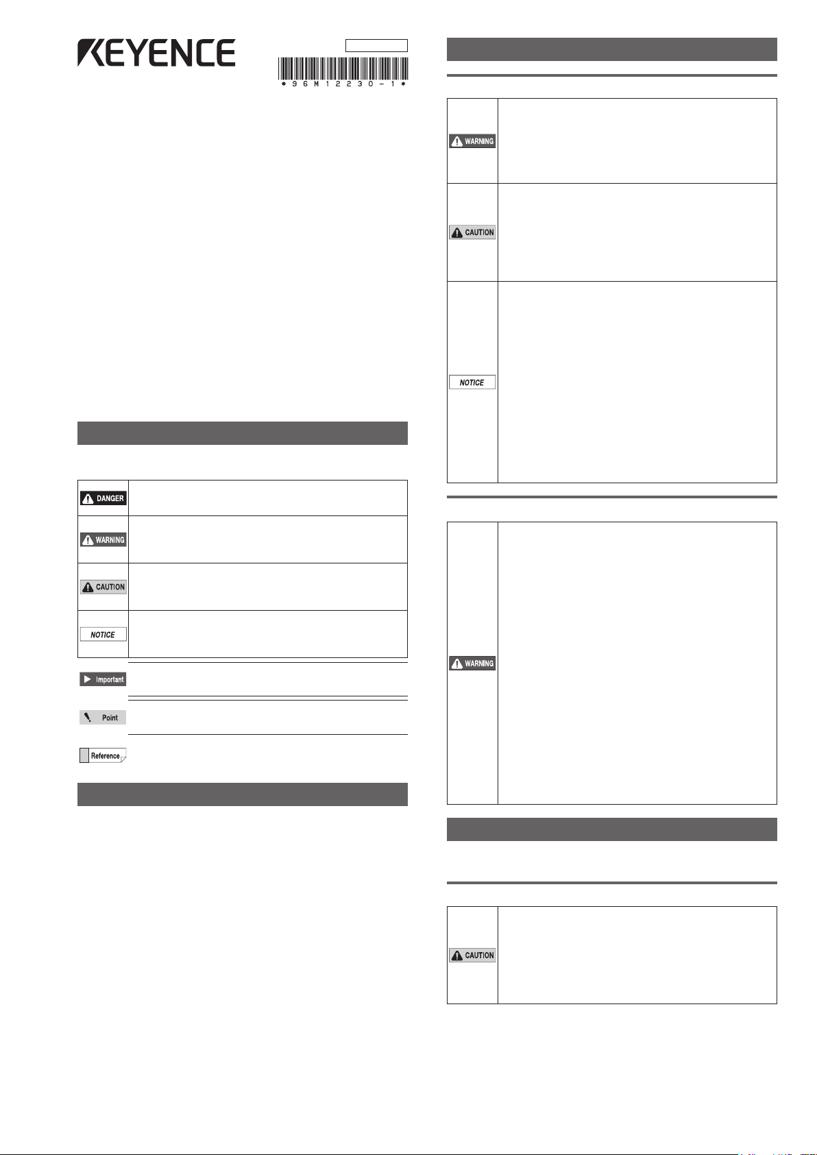
Symbols
The following symbols alert you to important messages.
Be sure to read these messages carefully.
It indicates a hazardous situation which, if not
avoided, will result in death or serious injury.
It indicates a hazardous situation which, if
not avoided, could result in death or serious
injury.
It indicates a hazardous situation which, if not
avoided, could result in minor or moderate
injury.
It indicates a situation which, if not avoided,
could result in product damage as well as
property damage.
It indicates cautions and limitations that must
be followed during operation.
It indicates additional information on proper
operation.
It indicates tips for better understanding or useful
information.
Cautions
(1) Unauthorized reproduction of this manual in whole or
part is prohibited.
(2) The contents of this manual may be changed for
improvements without prior notice.
(3)
An utmost effort has been made to ensure the contents of
this manual are as complete as possible. If there are any
mistakes or questions, please contact a KEYENCE ofce
listed in the back of the manual.
(4) Regardless of item (3), KEYENCE will not be liable for
any effect resulting from the use of this unit.
(5) Any manuals with missing pages or other paging faults
will be replaced.
The company names and product names used in this
manual are registered trademarks or the trademarks of their
respective companies.
Safety Information for IV series
General Precautions
Do not use this product for the purpose to
protect a human body or a part of human body.
This product is not intended for use as an
explosion-proof product. Do not use this
product in a hazardous location and/or
potentially explosive atmosphere.
You must verify that the IV Series are
operating correctly in terms of functionality
and performance before the start and the
operation of the IV Series.
We recommend that you take substantial
safety measures to avoid any damage in the
event of a problem occurring.
KEYENCE never warrants the function or
performance of the IV Series if it is used in manner
that differs from the IV Series specications
contained in this instruction manual or if the IV
Series are modied by yourself.
When the IV Series is used in combination with
other instruments, functions and performance
may be degraded, depending on operating
conditions and the surrounding environment.
Do not place the instruments, including
peripherals, under rapid temperature
change. It may cause condensation and may
damage instruments or peripherals.
Remove the power cable from the power supply
if you do not use this product for a long time.
Safety precautions on LED product
Use of controls or adjustments or
performance of procedures other than those
specied herein may result in hazardous
radiation exposure. Follow the instructions
mentioned in this manual. Otherwise, injury to
the human body (eyes and skin) may result.
Do not stare into the direct or specularly
reected beam.
Do not disassemble this product. The laser
radiation emission from this product is not
automatically stopped when it is disassembled.
Do not direct the beam at people or into
areas where people might be present.
Be careful of the path of the LED beam.
If there is a possibility that the operator
may be exposed to the specular or diffuse
reections, block the beam by installing a
protective enclosure.
Install this product so that the path of the
LED beam is not as the same height as that
of human eye.
Important Instructions
Observe the following precautions to prevent malfunction of
the IV Series and to ensure that it is used properly.
Precautions on use
The power of this product and instruments
connected to this product must be turned off
when the cable is to be installed or removed.
Failure to do so may cause an electric shock
or a product damage.
Use this product in the correct supply voltage.
Failure to do so may cause a product damage.
1
IV Series (Sensor) - IM_E
Page 2
For instructions
Do not turn OFF the power while setting the
items or saving the settings. Otherwise, all
or part of the setting data may be lost.
Do not let water, dust or oil stick to the
camera/light of the sensor. Failure to do so
may cause a malfunction.
When this product becomes dirty, do not rub it with
a wet cloth, benzene, thinner, or alcohol. Doing so
may change the color or shape of the unit.
If the unit is heavily contaminated, disconnect
all the cables including the power supply cable,
wipe off the dirt with a cloth soaked with mild
detergent, and then wipe with a soft dry cloth.
For external master image registration
When the external master image registration is used
frequently, set "Write ROM when registering external
master" of the input option to "No" for nonvolatile
memory protection of the internal sensor. When the
option is set to "Yes", the nonvolatile memory is
guaranteed to write for 100,000 times.
For automatic focus function
Automatic focus function is used for adjusting
the focusing position at the time of installation.
This will not activate during the operation.
Focusing position can be registered in each
program. The program congurations are
guaranteed to switch for 100,000 times. If the
focusing position does not need to change
for each program, set "AF Adjustment Pos"
to "Common" for extending the life-span.
Do not apply shock or vibration during the
focusing position adjustment . Failure to
do so may cause a product damage.
Measures to be taken when an abnormality occurs
In the following cases, turn the power OFF
immediately. Using the IV Series in an abnormal
condition could cause re, electric shock, or
malfunction. Contact our ofce for repair.
If water or debris enters the IV Series.
If the IV Series is dropped or the case is damaged.
If abnormal smoke or odor emanates from
the IV Series.
Precautions on installation
To use this product correctly and safely, avoid
installing it in the following locations. Failure to do
so may cause re, electric shock, or malfunction.
Outdoors
Altitude above 2000 m
Locations that are humid, dusty or poorly
ventilated
Locations where the temperature is high
such as those exposed to direct sunlight
Locations where there are ammable or
corrosive gases
Locations where the unit may be directly
subjected to vibration or impact
Locations where water, oil, or chemicals
may splash onto the unit
To improve the anti-noise feature, install
the unit following the precautions below.
Otherwise, a malfunction may occur.
Mount the sensor onto the insulated
attached mounting adapter.
Ground the FG cable (drain cable) of the sensor.
Do not mount the unit in a cabinet where
high-voltage equipment is already installed.
Mount the unit as far from power lines as possible.
Separate the unit as far as possible from the
devices that emit strong electric or magnetic
eld (such as solenoid or chopper).
Separate the I/O signal line from the power
line or high-voltage line.
For power supply
Noise superimposed on the power supply could
cause malfunction. Use a stabilized DC power
supply congured with an isolation transformer.
When using a commercially available
switching regulator, be sure to ground the
frame ground terminal.
Devices including this unit are precision
components. Do not apply shock or vibration.
When connecting to a network, let engineers
who are knowledgeable about networks
handle it.
Precautions on Regulations and Standards
UL Certication
This product is a UL/C-UL Listed product.
UL File No. E301717
Category NRKH, NRKH7
Be sure to consider the following specications when using
this product as a UL Listed product.
Use a power supply with Class 2 output dened in NFPA70
(NEC: National Electrical Code).
Power supply/ External input/ Control output shall be
connected to a single Class 2 source only.
Use with an over current protection device which is rated
24 V or more and not more than 1 A.
Enclosure Type 1 (Based on UL50)
CE Marking
Keyence Corporation has conrmed that this product
complies with the essential requirements of the applicable
EC Directive, based on the following specications. Be sure
to consider the following specications when using this
product in the Member State of European Union.
EMC Directive (2004/108/EC)
Applicable Standard EMI: EN60947-5-2, Class A
EMS: EN60947-5-2
The length of power/IO cable, Ethernet cable and
Monitor cable must be less than or equal to 30m.
Remarks:
These specications do not give any guarantee that the
end-product with this product incorporated complies with the
essential requirements of EMC Directive. The manufacturer
of the end-product is solely responsible for the compliance
on the end-product itself according to EMC Directive.
Low-Voltage Directive (2006/95/EC)
Applicable Standard: EN62471
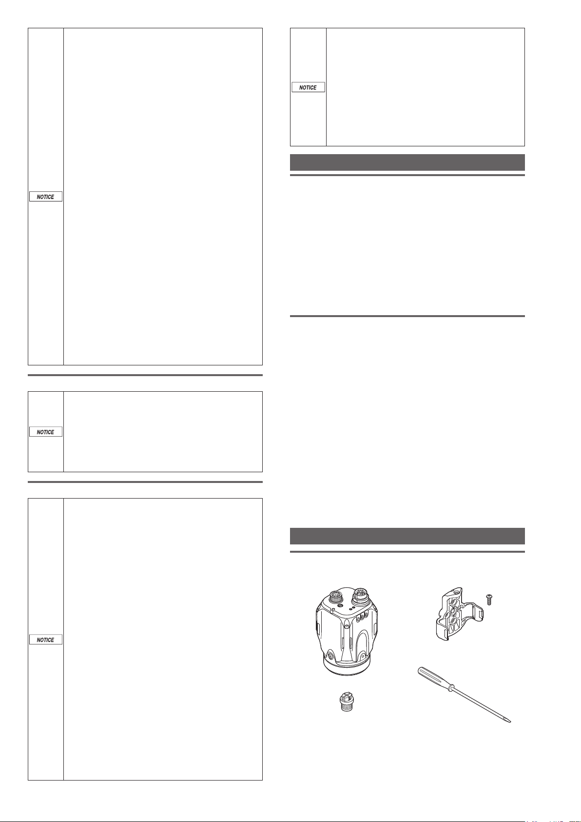
Checking the Package Contents
Sensor
IV-500C
IV-500CA
Waterproof cap for Ethernet
connector x 1
Instruction Manual x 1 (This manual)
The mounting adapter is mounted on the monitor in the
default factory setting.
IV-150M
IV-150MA
Sensor x 1
IV-500M
IV-500MA
Mounting adapter x 1
Screw for mounting adapter x 1
Flathead screwdriver x1
(Manual focus type only)
IV-2000M
IV-2000MA
IV Series (Sensor) - IM_E
2
Page 3
Optional parts for sensor
1
Dome attachment
IV-D10
Mounting screw x 2
Hexagon wrench
Dome attachment x 1
Polarized visible light lter attachment
OP-87436
Polarized visible light lter
attachment x 1
Infrared polarization lter attachment
OP-87437
Infrared polarization lter
attachment x 1
Power I/O cable (M12 12pin - strand wire)
OP-87440 (2m)
Power I/O cable (M12 12pin - strand wire) x 1
Mounting adapter
OP-87460
Mounting adapter x 1
Same as the accessories for sensor.
Optional parts in case of loss/damage.
Front cover (for replacement)
OP-87461
Front cover (for
replacement) x 1
Optional parts for replacement.
Bracket
OP-87685×1
OP-87441 (5m)
Mounting screw x 2
O-shaped ring
(Small x 2, Large x 1)
(L-shaped) x 1
Instruction Manual x 1
Mounting screw x 2
Instruction Manual x 1
Mounting screw x 2
Instruction Manual x 1
OP-87442 (10m)
Screw for mounting
adapter x 1
Hexagon wrench
(L-shaped) x 1
Instruction
Manual x 1
Mounting screw for
bracket + Nut x 1
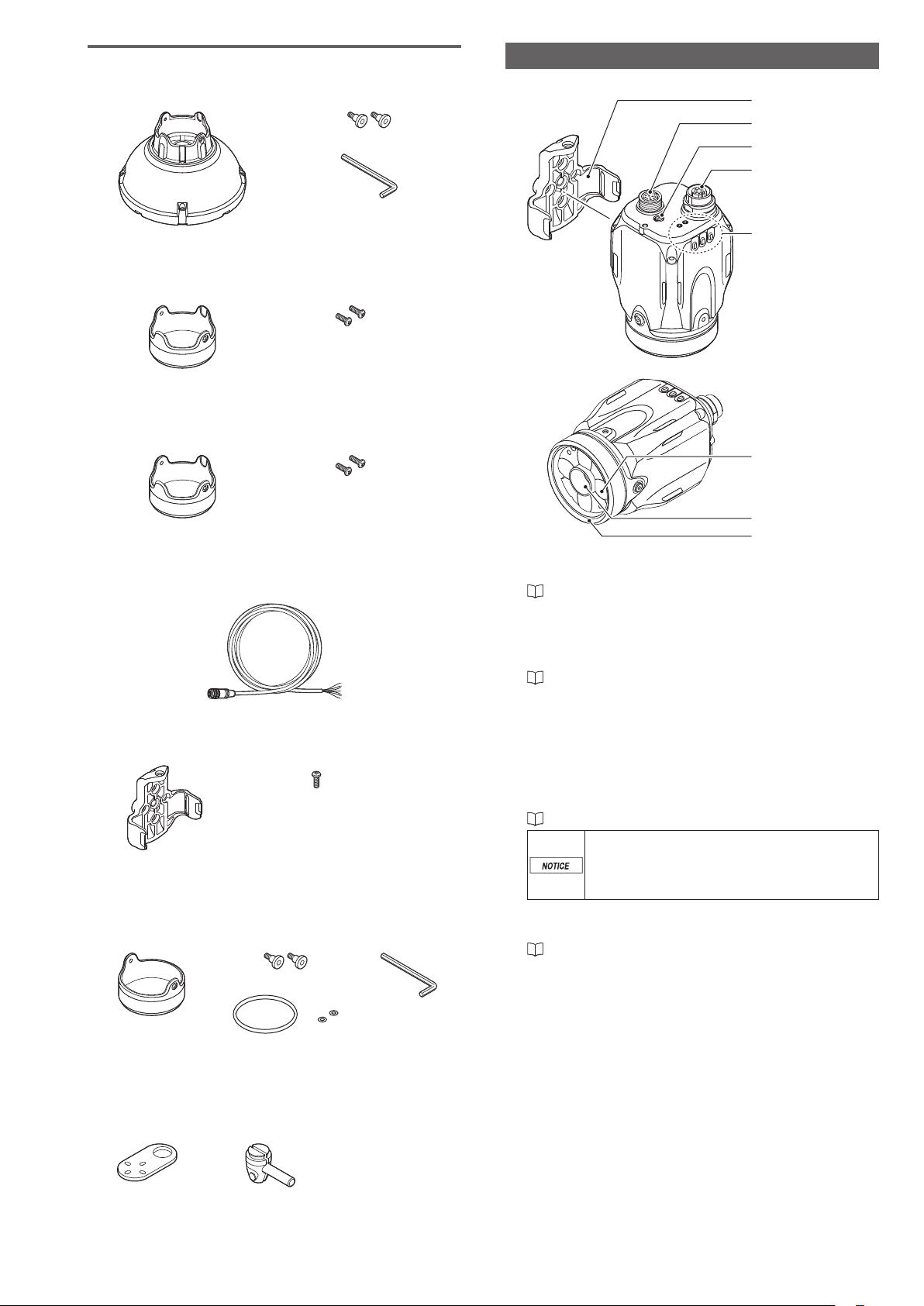
Name and function of each part
Name and function of each part of sensor
2
3
4
5
6
7
8
1 Sensor mounting adapter
Use this for mounting and xing the sensor.
“Mounting” (Page 4)
2 Connector for power I/O cable
Connector for connecting a power I/O cable.
Use this for supplying power to the sensor and for
connecting with external devices.
“Cables” (Page 6)
3 Focusing position adjustment screw
(manual focus type only)
Adjusts the focus of displayed images.
4 Connector for monitor cable/Ethernet cable
Connector for connecting a monitor cable or Ethernet
cable. Use this for connecting the monitor, PC, or Ethernet
switch.
“Cables” (Page 6)
When the cable is not connected, attach
the waterproof cap for Ethernet connector
to maintain enclosure rating.
Tightening torque : 0.45 to 0.55 N·m
5 Indicator light
Indicates the operating status of the sensor.
“Operation of the indicator light” (Page 4)
6 Built-in light
LED light that illuminates the object.
7 Camera
Images the object.
8 Front cover
Protects the camera and built-in lights.
The front cover is protected by the protection sheet (blue)
in the default factory setting.
Remove the sheet when the sensor is to be used.
Front cover for replacement is provided for maintenance.
Bracket A x 1
Bracket B x 1
Screw for mounting
adapter x 4
3
IV Series (Sensor) - IM_E
Page 4

Operation of the indicator light
600
Details on operations of indicator light are shown below.
4 5
1 2 3
1 PWR/ERR
Indicates the power supplying status to the sensor and
error status of the sensor.
Green (ON)
Green (Blink)
...... Operating.
.... Setting processing. Operation is
stopped. Blinks once a second.
Red (ON) .......... Unrecoverable error has occurred.
Red (Blink)
(OFF)
....... Recoverable error has occurred.
............... Power is not supplied.
Adjusting the focusing position (manual
focus only).
2 OUT
Indicates the comprehensive results.
............... Comprehensive result is "OK".
Green
.................. Comprehensive result is "Fail".
Red
............... Setting processing.
(OFF)
Standby status until the rst judge
nishes after starting the operation or
after switching the program number.
Orange (Blink)
... Indicates the focusing status while
adjusting the focusing position with
the blinking speed (manual focus type
only).
3 TRIG
Green light lights up (one-shot) according to input of the
internal or external trigger.
4 STATUS
Indicates the connection status within the monitor.
Green (ON)
...... Normally connected with monitor or
PC.
Green (Blink)
.... IP address has been retrieved but the
sensor is not correctly connected with
monitor or PC.
............... IP address is not assigned.
(OFF)
Sensor is
not correctly connected with monitor or
PC.
Orange (Blink)
... Indicates the focusing status while
adjusting the focusing position with
the blinking speed (manual focus type
only).
5 LINK/ACT
Indicates the linking status within monitor or Ethernet
switch.
Green (ON)
Green (Blink)
...... Normally linked.
.... Normally linked, and the data is
sending/receiving.
............... Sensor is not normally linked.
(OFF)
Mounting
Ground (functional ground) the drain cable
(FG) of the power I/O cable.
Mount and insulate the sensor. Use the
attached mounting adapter to insulate.
Sensor case has been grounded. If the
sensor is not insulated, electric potential and
noises may cause a damage or malfunction.
Do not place the sensor in the environment
that exceeds the limit of sensor's resistance
to the environment, or environment that
propagates the vibration directly to the
sensor. Those may cause a damage or
malfunction.
Manual focus type needs to adjust the
focusing position after installed. Reserve
enough space to adjust and install it.
At the time of installation, it is better to
enable the position or direction adjustment
of the sensor by installing the adjustment
system at the sensor mounting area.
View and optical axis have individual
differences. Adjust the position by checking
the actual image at the time of installation.
Place the sensor where no ambient light has
effect. Ambient light includes solar light,
lights of other devices, and photoelectric
sensors. Also, be careful when the light
intensity of the ambient light changes. Use
the shield to protect when the location
cannot be changed.
Place the sensor where no object can block
out the internal light or the view of the
sensor.
Detection may become unstable due to the
lights if multiple sensors are placed nearby
each other. Delay the timing of external
trigger inputs or use the shield to avoid
interference.
Checking the view and installed distance
For IV series, installed distance between the view and object
is different depending on the type of the sensor. Check the
type of the sensor to be used and its view, and place it in the
proper distance.
View H
Indicator light
View V = View H x 0.75
(H : V = 4 : 3)
Standard-range type (color / monochrome)
500
View V
Installed distance WD
IV Series (Sensor) - IM_E
400
300
200
150
100
Installed distance WD (mm)
50
0
5025 70 100 150130 200 250
210
View H (mm)
4
Page 5

Short-range type
2500
150
100
50
Mounting the sensor onto the mounting adapter
Mount the sensor to the left and right stopper on
1
the mounting adapter.
Sensors cannot be mounted on the side with the
indicator light.
Indicator light
Installed distance WD (mm)
0
Long-rang type
2000
1500
1000
500
300
Installed distance WD (mm)
0
The value of View H and V will be a half of the value on
the gures above when using the digital zooming function
(monochrome type only).
10 20 30 4012 36
View H (mm)
10045 200 300 400
View H (mm)
Mounting the mounting adapter
Use the mounting adapter (accessory or OP-87460) to
mount the sensor.
The mounting adapter is mounted on the
sensor in the default factory setting. Remove
it from the sensor.
“Unmounting the sensor” (Page 5)
Push the sensor to the
stopper of xing screw
Push until you hear the clicking
sound from the both side stoppers
Fix the mounting adapter and sensor using the
2
attached screws.
Screw : M3 x 1
Use the attached screws.
Tightening torque : 0.45 to 0.55 N·m
Mounting on the wall
Screw : M3 x 4
Use the commercially available screws which have head
thickness of 3 mm or lower.
Tightening torque : 1.0 N·m or lower
Mounting from the jig side
Screw : M4 x 4
Use the commercially available screws.
Tightening torque : 1.5 N·m or lower
Remove the protection
sheet (blue)
Unmounting the sensor
Dismount the screw.
1
Pull out the stopper of the mounting adapter and
2
unmount the sensor.
For details on mounting hole dimensions, refer
to “Dimensions” (Page 8).
Pull out the
stopper
5
IV Series (Sensor) - IM_E
Page 6

Cables
Connecting the power I/O cable of the sensor
Adjust the pins of the connector for the power I/O
1
cable and pin connection of the cable connector,
and connect the cable to the sensor.
Selecting PNP output
When PNP is selected in I/O format
Brown (DC24V)
Pink/Yellow/
Light Blue/Purple/
Green/Red
(IN)
Black/White/Gray/
Orange
(OUT)
OUT
External device
(PNP)
DC24V
IN
Adjust the pins and the
pin connection
Tighten the connector by turning the screw-on
2
connector in the clockwise direction.
Tightening torque of the screws needs to be 1.0 to 1.5 N·m.
When connecting the connector, insert it
without tipping and tighten it well. If the
tightening is weak, it may cause a bad
connection and vibration can loosen the
connector. Also, the enclosure rating may
not be maintained with loose connection.
* Indication is retightening approximately
90° to 120° with tools such as pliers
after tightening with hands.
Wire each cable according to its intended purpose.
3
Selecting NPN output
When NPN is selected in I/O format
Brown (DC24V)
Black/White/Gray/
Orange
(OUT)
Pink/Yellow/
Light Blue/Purple/
Green/Red
(IN)
Blue (0V)
Drain wire (FG)
External device
Load
IN
DC24V
OUT
(NPN)
Blue (0V)
Drain wire (FG)
Black (OUT1) / White (OUT2) /
Gray (OUT3) / Orange (OUT4)
Pink (IN1 : External trigger) / Yellow (IN2) /
Light Blue (IN3) / Purple (IN4) /Green (IN5)
/ Red (IN6)
Use it by assigning the optional function to
OUT1 to OUT4 and IN2 to IN6.
Wiring
color
Brown DC24V - + side of power
Blue 0V -
Black OUT1
White OUT2 BUSY (N.O.)
Gray OUT3 Error (N.O.)
Orange OUT4 OFF
Pink IN1
Yellow IN2 OFF
Light Blue
Purple IN4 OFF
Green IN5 OFF
Red IN6 OFF
Drain FG - Insulated frame
Cable
specication
Name
IN3 OFF
The output assignment, N.O./N.C., and input line
assignment can be changed. For details, refer to
the User's Manual.
Assigning
default value
Total judge
(N.O.)
External
trigger ↑
Brown/Blue/Black/White/Gray/Orange
: AWG25
Pink/Yellow/Light Blue/Purple/Green/
Red : AWG28
With braided shield cable (with drain cable)
Load
Description
- side of power
GND of input-output cable
Output assignable
function
Total Status
Tot.StatusNG
RUN
BUSY
Error
Pos. Adj.
Judge result of each
tool (Tool 1 to Tool 16)
Result of the logical
operation of each tool
(Logic 1 to Logic 4)
OFF (not used)
Set external trigger.
Activation timing (↑) or
deactivation timing (↓)
can be set.
Input assignable function
Program bit0 to bit4
Clear error
External master
OFF (not used)
Black (OUT1) / White (OUT2) /
Gray (OUT3) / Orange (OUT4)
Pink (IN1 : External trigger) / Yellow (IN2) /
Light Blue (IN3) / Purple (IN4) / Green (IN5)
/ Red (IN6)
Use it by assigning the optional function to
OUT1 to OUT4 and IN2 to IN6.
IV Series (Sensor) - IM_E
Individually insulate the non-used input-
output cables.
For input cables of this sensor, connect with
non-contact output (transistor output/SSR
output). For contact output (relay output),
incorrect input may be operated due to the
contact bouncing in the system.
6
Page 7

Circuit Diagram
DC24V
DC24V
Input circuit
No-voltage input (When NPN output is selected)
When NPN is selected in I/O format, the circuit becomes
no-voltage input circuit. External power supply is not
necessary.
ON voltage : 2 V or lower
OFF current : 0.1 mA or lower
ON current : 2 mA (short circuit)
+3.3V
Main circuit
* Pink (IN1 : External trigger) / Yellow (IN2) / Light Blue (IN3) /
Purple (IN4) / Green (IN5) / Red (IN6)
Use by assigning the optional functions to IN2 to 6
Voltage input (When PNP output is selected)
When PNP is selected in I/O format, the circuit becomes
voltage input circuit.
Input maximum rating : 26.4 V
ON voltage : 15 V or higher
ON current : 2 mA (for 24V)
OFF current : 0.2 mA or lower
Brown
IN1 - IN6
*
0V
Blue
Output circuit
When NPN output is selected
When NPN is selected in I/O format, the circuit becomes
open collector N
PN output circuit
Maximum rating : 26.4 V, 50 mA
Remaining voltage : 1.5 V or lower
Main circuit
* Black (OUT1) / White (OUT2) / Gray (OUT3) / Orange (OUT4)
Use by assigning the optional functions to OUT1 to OUT4
When PNP output is selected
Overcurrent
When PNP is selected in I/O format, the circuit becomes
open collector
PNP output circuit
Maximum rating : 26.4 V, 50 mA
Remaining voltage : 2 V or lower
.
DC24V
Brown
Load
OUT1 - OUT4
*
protection circuit
0V
Blue
.
DC24V
Brown
Brown
IN1 - IN6
*
Main circuit
0V
Blue
* Pink (IN1 : External trigger) / Yellow (IN2) / Light Blue (IN3) /
Purple (IN4) / Green (IN5) / Red (IN6)
Use by assigning the optional functions to IN2 to 6
OUT1 - OUT4
*
Main circuit
* Black (OUT1) / White (OUT2) / Gray (OUT3) / Orange (OUT4)
Use by assigning the optional functions to OUT1 to OUT4
Overcurrent
protection circuit
0V
Blue
Load
7
IV Series (Sensor) - IM_E
Page 8

Dimensions
(102)
0.4 112.5
93
56
Sensor
IV-500C / IV-500CA / IV-500M / IV-500MA / IV-150M / IV-150MA / IV-2000M / IV-2000MA
R50
52
R50
50
56
WD reference surface
32.4
57.4
0.4
50
20
81.5
58
45.5 25
Mounting
adapter
Power I/O cable
OP-87440 (2m) / OP-87441 (5m) / OP-87442 (10m)
45
φ15
φ6.7
2000
5000
10000
120 5
150
180
5
5
1/4-20UNC
(Depth 6mm)
4-M4
(Depth 6mm)
10.5 10.5
(108)
Focusing position adjustment screw
610.5
(MF type only)
3-M3
(Depth 6mm)
20.5
41
Bracket
OP-87685
50
IV Series (Sensor) - IM_E
(99)
48.4
31.6
99
58
19.6
41
82.5
8
Page 9

Specications
Model IV-500C IV-500CA IV-500M IV-500MA IV-150M IV-150MA IV-2000M IV-2000MA
Installed distance Standard distance (50 to 500 mm)
Short range (50 to 150 mm)
Installed distance 50 mm :
View
Installed distance 50 mm : 25 (H) x 18 (V) mm
to
Installed distance 500 mm : 210 (H) x 157 (V) mm
12 (H) x 9 (V) mm
to
Installed distance 150 mm :
36 (H) x 27 (V) mm
Image sensor 1/3 inch color CMOS 1/3 inch monochrome CMOS
Pixel 752 (H) x 480 (V)
Focus adjustment Manual Auto
*1
Manual Auto
*1
Manual Auto
Exposure time 1/10 to 1/50,000 1/10 to 1/25,000 1/20 to 1/25,000 1/10 to 1/25,000
Lights
Tools
Amplier type White LED Red LED Infrared LED
Lighting method
Type Outline search, Color area
Number
Pulse lighting/DC lighting is switchable
*7
*2
Detection tools : 16 tools, Position adjustment tool : 1 tool
, Area*8, Position adjustment
Switch settings (programs) 32 programs
Image
history
Numbers 100 images
*3
Condition NG only/All is selectable
*4
300 images
*5
OFF/Statistics/Histograms is switchable
Statistics : Processing time (latest value, MAX, MIN, AVE), numbers of OKs, numbers of NGs,
Analysis information
Other functions
Indicators
*6
trigger numbers, trigger errors, judge results list by tools
Histograms :
Histogram, matching degree (latest value, MAX, MIN, AVE), numbers of OKs, numbers of NGs
HDR, HighGain, Color lters*7, Digital zoom*8, Brightness correction, Tilt correction, White balance*7,
Mask outline, Mask area, Test run, ToolAutoTune, Input monitor, Output test, Security settings, Simulator
PWR/ERR, OUT, TRIG, STATUS, LINK/ACT
No-voltage input/voltage input is switchable
Input
For no-voltage input
For voltage input
:
ON voltage 2V or lower, OFF current 0.1mA or lower, ON current 2mA (short circuit)
:
Maximum input rating 26.4V, ON voltage 15V or higher, OFF
lower, ON current 2mA (for 24V)
Inputs 6 inputs (IN1 to IN6)
Function
IN1 : External trigger, IN2 to IN6 : Enable by assigning the optional functions
Assignable functions :
Program switching, Clear error, External master image registration
Open collector output NPN/PNP is switchable, N.O./N.C. is switchable
Output
For open collector NPN output : Maximum rating 26.4V 50mA, remaining voltage 1.5V or lower
For open collector PNP output : Maximum rating 26.4V 50mA, remaining voltage 2V or lower
Outputs 4 outputs (OUT1 to OUT4)
Enable by assigning the optional functions
Function
Assignable functions : Total judge result, RUN, BUSY, Error, Position adjustment result, Judge
result of each tool, Result of the logical operation of each tool
Standard 100BASE-TX/10BASE-T
Ethernet
*10
Connector M12 4pin connector
Network function FTP client, EtherNet/IP, PROFINET
Power voltage DC 24V ± 10% (including ripple)
Rating
Environmental
resistance
Consumption
current
Ambient
temperature
Relative humidity
0.6 A or less
0 to +50°C (No freezing)
35 to 85%RH (No condensation)
Vibration 10 to 55 Hz, 1.5 mm double amplitude, 2 hours each for X, Y, and Z axes
Shock resistance
Enclosure rating
500m/s2 6 different directions in 3 times
*11
IP67
Material Main unit case : Aluminum die-casting, Packing : NBR, Front Cover : Acrylic, Mounting adapter : POM
Weight Approx. 270 g
*1 The focusing position can be automatically adjusted at the time of installation. Deactivated during the operation. The focusing
position can be registered by programs.
*2 Tools can be installed by programs.
*3 Saves to the memory in the sensor.
The images saved in the sensor can be backed up to the USB memory installed to the intelligent monitor (IV-M30) or to the
PC by the software for IV (IV-H1).
*4 When using the FTP client function ; 70 pictures
*5 When using the FTP client function ; 210 pictures
*6 This can be displayed on the intelligent monitor (IV-M30) or by the software for IV (IV-H1).
*7 Color type only.
*8 Monochrome type only.
*9 This function can be used with the software for IV (IV-H1).
*10 This is for connection with the intelligent monitor (IV-M30) or the software for IV (IV-H1).
*11 Except when polarized lter attachment (OP-87436/OP-87437) is mounted.
Long range (300 to 2000 mm)
Installed distance 300 mm :
45 (H) x 33 (V) mm
Installed distance 2000 mm :
300 (H) x 225 (V) mm
*1
Manual Auto
current
to
*1
*9
0.2mA or
9
IV Series (Sensor) - IM_E
Page 10

Warranties and Disclaimers
(1) KEYENCE warrants the Products to be free of defects in materials and
workmanship for a period of one (1) year from the date of shipment. If any
models or samples were shown to Buyer, such models or samples were
used merely to illustrate the general type and quality of the Products and not
to represent that the Products would necessarily conform to said models or
samples. Any Products found to be defective must be shipped to KEYENCE
with all shipping costs paid by Buyer or offered to KEYENCE for inspection and
examination. Upon examination by KEYENCE, KEYENCE, at its sole option,
will refund the purchase price of, or repair or replace at no charge any Products
found to be defective. This warranty does not apply to any defects resulting from
any action of Buyer, including but not limited to improper installation, improper
interfacing, improper repair, unauthorized modication, misapplication and
mishandling, such as exposure to excessive current, heat, coldness, moisture,
vibration or outdoors air. Components which wear are not warranted.
(2) KEYENCE is pleased to offer suggestions on the use of its various Products.
They are only suggestions, and it is Buyer's responsibility to ascertain the
tness of the Products for Buyer’s intended use. KEYENCE will not be
responsible for any damages that may result from the use of the Products.
(3) The Products and any samples ("Products/Samples") supplied to Buyer are not
to be used internally in humans, for human transportation, as safety devices or
fail-safe systems, unless their written specications state otherwise. Should any
Products/Samples be used in such a manner or misused in any way, KEYENCE
assumes no responsibility, and additionally Buyer will indemnify KEYENCE and
hold KEYENCE harmless from any liability or damage whatsoever arising out of
any misuse of the Products/ Samples.
(4) OTHER THAN AS STATED HEREIN, THE PRODUCTS/SAMPLES ARE
PROVIDED WITH NO OTHER WARRANTIES WHATSOEVER. ALL EXPRESS,
IMPLIED, AND STATUTORY WARRANTIES, INCLUDING, WITHOUT
LIMITATION, THE WARRANTIES OF MERCHANTABILITY, FITNESS FOR A
PARTICULAR PURPOSE, AND NON-INFRINGEMENT OF PROPRIETARY
RIGHTS, ARE EXPRESSLY DISCLAIMED. IN NO EVENT SHALL KEYENCE
AND ITS AFFILIATED ENTITIES BE LIABLE TO ANY PERSON OR ENTITY
FOR ANY DIRECT, INDIRECT, INCIDENTAL, PUNITIVE, SPECIAL OR
CONSEQUENTIAL DAMAGES (INCLUDING, WITHOUT LIMITATION, ANY
DAMAGES RESULTING FROM LOSS OF USE, BUSINESS INTERRUPTION,
LOSS OF INFORMATION, LOSS OR INACCURACY OF DATA, LOSS
OF PROFITS, LOSS OF SAVINGS, THE COST OF PROCUREMENT OF
SUBSTITUTED GOODS, SERVICES OR TECHNOLOGIES, OR FOR ANY
MATTER ARISING OUT OF OR IN CONNECTION WITH THE USE OR
INABILITY TO USE THE PRODUCTS, EVEN IF KEYENCE OR ONE OF ITS
AFFILIATED ENTITIES WAS ADVISED OF A POSSIBLE THIRD PARTY’S
CLAIM FOR DAMAGES OR ANY OTHER CLAIM AGAINST BUYER. In some
jurisdictions, some of the foregoing warranty disclaimers or damage limitations
may not apply.
BUYER'S TRANSFER OBLIGATIONS:
If the Products/Samples purchased by Buyer are to be resold or delivered to a
third party, Buyer must provide such third party with a copy of this document, all
specications, manuals, catalogs, leaets and written information provided to
Buyer pertaining to the Products/Samples.
E 1101-3
IV Series (Sensor) - IM_E
Copyright (c) 2012 KEYENCE CORPORATION. All rights reserved.
12230E 1122-1 96M12230 Printed in Japan
10
 Loading...