

Page 1
Service and Maintenance Manual
MODEL
9MP
3121163
May 14, 2003
ANSI
Page 2

CALIFORNIAN PROPOSITION 65
BATTERY WARNING
Battery posts,
terminals and related
accessories contain
lead and lead compounds,
chemical known to the
State of Califormia
to cause cancer and
reproductive harm.
WASH HANDS
AFTER HANDLING!
JLG Industries (Australia)
P.O. Box 5119
11 Bolwarra Road
Port Macquarie
N.S.W. 2444
Australia
Phone: (61) 2 65 811111
Fax: (61) 2 65 810122
JLG Latino Americana Ltda.
Rua Eng. Carlos Stevenson,
80-Suite 71
13092-310 Campinas-SP
Brazil
Phone: (55) 19 3295 0407
Fax: (55) 19 3295 1025
JLG Industries (Europe)
Kilmartin Place,
Tannochside Park
Uddingston G71 5PH
Scotland
Phone: (44) 1 698 811005
Fax: (44) 1 698 811055
JLG Industries (UK)
Unit 12, Southside
Bredbury Park Industrial Estate
Bredbury
Stockport
SK6 2sP
England
Phone: (44) 870 200 7700
Fax: (44) 870 200 7711
JLG Europe B.V.
Jupiterstraat 234
2132 HJ Foofddorp
The Netherlands
Phone: (31) 23 565 5665
Fax: (31) 23 557 2493
JLG Industries (Pty) Ltd.
Unit 1, 24 Industrial Complex
Herman Street
Meadowdale
Germiston
South Africa
Phone: (27) 11 453 1334
Fax: (27) 11 453 1342
JLG Deutschland GmbH
Max Planck Strasse 21
D-27721 Ritterhude/lhlpohl
Bei Bremen
Germany
Phone: (49) 421 693 500
Fax: (49) 421 693 5035
JLG Industries (Norge AS)
Sofeimyrveien 12
N-1412 Sofienyr
Norway
Phone: (47) 6682 2000
Fax: (47) 6682 2001
Plataformas Elevadoras
JLG Iberica, S.L.
Trapadella, 2
P.I. Castellbisbal Sur
08755Castellbisbal
Spain
Phone: (34) 93 77 24700
Fax: (34) 93 77 11762
JLG Industries (Italia)
Via Po. 22
20010 Pregnana Milanese - MI
Italy
Phone: (39) 02 9359 5210
Fax: (39) 02 9359 5845
JLG Polska
UI. Krolewska
00-060 Warsawa
Poland
Phone: (48) 91 4320 245
Fax: (48) 91 4358 200
JLG Industries (Sweden)
Enkopingsvagen 150
Box 704
SE - 175 27 Jarfalla
Sweden
Phone: (46) 8 506 59500
Fax: (46) 8 506 59534
Page 3
INTRODUCTION - MAINTENANCE SAFETY PRECAUTIONS
MAINTENANCE SAFETY PRECAUTIONS
A. GENERAL
This section contains the general safety precautions
which must be observed during maintenance of the aerial
platform. It is of utmost importance that maintenance personnel pay strict attention to these warnings and precautions to avoid possible injury to themselves or others or
damage to the equipment. A maintenance program must
be established by a qualified person and must be followed
to ensure that the machine is safe to operate.
MODIFICATION OF THE MACHINE WITHOUT CERTIFICATION BY
A RESPONSIBLE AUTHORITY THAT THE MACHINE IS AT LEAST
AS SAFE AS ORIGINALLY MANUFACTURED IS A SAFETY VIOLATION.
The specific precautions to be observed during machine
maintenance are inserted at the appropriate point in the
manual. These precautions are, for the most part, those
that apply when servicing hydraulic and larger machine
component parts.
Your safety, and that of others, is the first consideration
when engaging in the maintenance of equipment. Always
be conscious of component weight and never attempt to
move heavy parts without the aid of a mechanical device.
Do not allow heavy objects to rest in an unstable position.
When raising a portion of the equipment, ensure that adequate support is provided.
SINCE THE MACHINE MANUFACTURER HAS NO DIRECT CONTROL OVER THE FIELD INSPECTION AND MAINTENANCE,
SAFETY IN THIS AREA IS THE RESPONSIBILITY OF THE OWNER/
OPERATOR.
C. MAINTENANCE
FAILURE TO COMPLY WITH SAFETY PRECAUTIONS LISTED IN
THIS SECTION COULD RESULT IN MACHINE DAMAGE, PERSONNEL INJURY OR DEATH AND IS A SAFETY VIOLATION.
• REMOVE ALL RINGS, WATCHES, AND JEWELRY
WHEN PERFORMING ANY MAINTENANCE.
• DO NOT WEAR LONG HAIR UNRESTRAINED, OR
LOOSE FITTING CLOTHING AND NECKTIES WHICH
ARE APT TO BECOME CAUGHT ON OR ENTANGLED
IN EQUIPMENT.
• OBSERVE AND OBEY ALL DANGER, WARNING, CAUTION AND OTHER INSTRUCTIONS ON MACHINE
AND IN SERVICE MANUAL.
• KEEP STANDING SURFACES AND HAND HOLDS
FREE OF OIL, GREASE, WATER, ETC.
• NEVER WORK UNDER AN ELEVATED PLATFORM
UNTIL PLATFORM HAS BEEN SAFELY RESTRAINED
FROM ANY MOVEMENT BY BLOCKING OR OVERHEAD SLING.
• BEFORE MAKING ADJUSTMENTS, LUBRICATING OR
PERFORMING ANY OTHER MAINTENANCE, SHUT
OFF ALL POWER CONTROLS.
•BATTERY SHOULD ALWAYS BE DISCONNECTED
DURING REPLACEMENT OF ELECTRICAL COMPONENTS.
• KEEP ALL SUPPORT EQUIPMENT AND ATTACHMENTS STOWED IN THEIR PROPER PLACE.
• USE ONLY APPROVED, NONFLAMMABLE CLEANING
SOLVENTS.
B. HYDRAULIC SYSTEM SAFETY
1. It should be particularly noted that the machines
hydraulic systems operate at extremely high and
potentially dangerous pressures. Every effort should
be made to relieve any system pressure prior to disconnecting or removing any portion of the system.
2. Relieve system pressure by activating the lift DOWN
control with the platform completely lowered to
direct any line pressure back into the return line to
the reservoir. Pressure feed lines to system components can then be disconnected with minimal fluid
loss.
3121163 – JLG Lift – a
Page 4

INTRODUCTION - REVISION LOG
October 10, 2002 – Original Issue of Manual
October 14, 2002 – Manual Revised
November 12, 2002 – Manual Revised
May 14, 2003 – Manual Revised
REVISION LOG
b – JLG Lift – 3121163
Page 5

TABLE OF CONTENTS
TABLE OF CONTENTS
SUBJECT - SECTION, PARAGRAPH PAGE NO.
SECTION - MAINTENANCE SAFETY PRECAUTIONS
A. GENERAL . . . . . . . . . . . . . . . . . . . . . . . . . . . . . . . . . . . . . . . . . . . . . . . . . . . . . . . . . . . . . . . . . . . . . . A
B. HYDRAULIC SYSTEM SAFETY . . . . . . . . . . . . . . . . . . . . . . . . . . . . . . . . . . . . . . . . . . . . . . . . . . . . . A
C. MAINTENANCE . . . . . . . . . . . . . . . . . . . . . . . . . . . . . . . . . . . . . . . . . . . . . . . . . . . . . . . . . . . . . . . . . A
REVISION LOG. . . . . . . . . . . . . . . . . . . . . . . . . . . . . . . . . . . . . . . . . . . . . . . . . . . . . . . . . . . . . . . . . . B
SECTION 1 - MACHINE SPECIFICATIONS
1.1 CAPACITIES. . . . . . . . . . . . . . . . . . . . . . . . . . . . . . . . . . . . . . . . . . . . . . . . . . . . . . . . . . . . . . . . . . .1-2
System Voltage . . . . . . . . . . . . . . . . . . . . . . . . . . . . . . . . . . . . . . . . . . . . . . . . . . . . . . . . . . . .1-2
Hydraulic System. . . . . . . . . . . . . . . . . . . . . . . . . . . . . . . . . . . . . . . . . . . . . . . . . . . . . . . . . . .1-2
1.2 COMPONENT DATA . . . . . . . . . . . . . . . . . . . . . . . . . . . . . . . . . . . . . . . . . . . . . . . . . . . . . . . . . . . .1-2
Hydraulic Pump/Pump Motor Assembly . . . . . . . . . . . . . . . . . . . . . . . . . . . . . . . . . . . . . . . . .1-2
Batteries/Battery Charger . . . . . . . . . . . . . . . . . . . . . . . . . . . . . . . . . . . . . . . . . . . . . . . . . . . .1-2
1.3 PERFORMANCE DATA . . . . . . . . . . . . . . . . . . . . . . . . . . . . . . . . . . . . . . . . . . . . . . . . . . . . . . . . . .1-2
Platform Capacity. . . . . . . . . . . . . . . . . . . . . . . . . . . . . . . . . . . . . . . . . . . . . . . . . . . . . . . . . . .1-2
Platform and Material Tray Size . . . . . . . . . . . . . . . . . . . . . . . . . . . . . . . . . . . . . . . . . . . . . . .1-2
Machine Height (platform stowed) . . . . . . . . . . . . . . . . . . . . . . . . . . . . . . . . . . . . . . . . . . . . . 1-2
Base Footprint . . . . . . . . . . . . . . . . . . . . . . . . . . . . . . . . . . . . . . . . . . . . . . . . . . . . . . . . . . . . .1-2
1.4 TORQUE REQUIREMENTS . . . . . . . . . . . . . . . . . . . . . . . . . . . . . . . . . . . . . . . . . . . . . . . . . . . . . . .1-2
1.5 LUBRICATION . . . . . . . . . . . . . . . . . . . . . . . . . . . . . . . . . . . . . . . . . . . . . . . . . . . . . . . . . . . . . . . . .1-2
Hydraulic Oil . . . . . . . . . . . . . . . . . . . . . . . . . . . . . . . . . . . . . . . . . . . . . . . . . . . . . . . . . . . . . .1-2
Lubrication Specifications . . . . . . . . . . . . . . . . . . . . . . . . . . . . . . . . . . . . . . . . . . . . . . . . . . . .1-3
1.6 HYDRAULIC PRESSURE ADJUSTMENT. . . . . . . . . . . . . . . . . . . . . . . . . . . . . . . . . . . . . . . . . . . . .1-3
1.7 CYLINDER SPECIFICATIONS . . . . . . . . . . . . . . . . . . . . . . . . . . . . . . . . . . . . . . . . . . . . . . . . . . . . .1-4
1.8 SERIAL NUMBER LOCATIONS . . . . . . . . . . . . . . . . . . . . . . . . . . . . . . . . . . . . . . . . . . . . . . . . . . . . 1-4
SECTION 2 - GENERAL
2.1 MACHINE PREPARATION, INSPECTION, AND MAINTENANCE . . . . . . . . . . . . . . . . . . . . . . . . . .2-1
General. . . . . . . . . . . . . . . . . . . . . . . . . . . . . . . . . . . . . . . . . . . . . . . . . . . . . . . . . . . . . . . . . . .2-1
Preparation, Inspection, and Maintenance . . . . . . . . . . . . . . . . . . . . . . . . . . . . . . . . . . . . . . . 2-1
Pre-Start Inspection . . . . . . . . . . . . . . . . . . . . . . . . . . . . . . . . . . . . . . . . . . . . . . . . . . . . . . . . . 2-1
Pre-Delivery Inspection and Frequent Inspection. . . . . . . . . . . . . . . . . . . . . . . . . . . . . . . . . . 2-1
Annual Machine Inspection . . . . . . . . . . . . . . . . . . . . . . . . . . . . . . . . . . . . . . . . . . . . . . . . . . .2-1
Preventative Maintenance . . . . . . . . . . . . . . . . . . . . . . . . . . . . . . . . . . . . . . . . . . . . . . . . . . . .2-1
2.2 PREVENTIVE MAINTENANCE AND INSPECTION SCHEDULE . . . . . . . . . . . . . . . . . . . . . . . . . . .2-2
2.3 SERVICING AND MAINTENANCE GUIDELINES. . . . . . . . . . . . . . . . . . . . . . . . . . . . . . . . . . . . . . . 2-5
General. . . . . . . . . . . . . . . . . . . . . . . . . . . . . . . . . . . . . . . . . . . . . . . . . . . . . . . . . . . . . . . . . . .2-5
Safety and Workmanship . . . . . . . . . . . . . . . . . . . . . . . . . . . . . . . . . . . . . . . . . . . . . . . . . . . .2-5
Cleanliness. . . . . . . . . . . . . . . . . . . . . . . . . . . . . . . . . . . . . . . . . . . . . . . . . . . . . . . . . . . . . . . .2-5
Components Removal and Installation . . . . . . . . . . . . . . . . . . . . . . . . . . . . . . . . . . . . . . . . . . 2-5
Component Disassembly and Reassembly . . . . . . . . . . . . . . . . . . . . . . . . . . . . . . . . . . . . . . 2-5
Pressure-Fit Parts. . . . . . . . . . . . . . . . . . . . . . . . . . . . . . . . . . . . . . . . . . . . . . . . . . . . . . . . . . . 2-5
Bearings. . . . . . . . . . . . . . . . . . . . . . . . . . . . . . . . . . . . . . . . . . . . . . . . . . . . . . . . . . . . . . . . . .2-5
Gaskets . . . . . . . . . . . . . . . . . . . . . . . . . . . . . . . . . . . . . . . . . . . . . . . . . . . . . . . . . . . . . . . . . .2-5
Bolt Usage and Torque Application . . . . . . . . . . . . . . . . . . . . . . . . . . . . . . . . . . . . . . . . . . . . 2-5
Hydraulic Lines and Electrical Wiring . . . . . . . . . . . . . . . . . . . . . . . . . . . . . . . . . . . . . . . . . . . 2-6
Hydraulic System. . . . . . . . . . . . . . . . . . . . . . . . . . . . . . . . . . . . . . . . . . . . . . . . . . . . . . . . . . .2-6
Lubrication and Servicing . . . . . . . . . . . . . . . . . . . . . . . . . . . . . . . . . . . . . . . . . . . . . . . . . . . .2-6
3121163 – JLG Lift – i
Page 6

TABLE OF CONTENTS
Batteries. . . . . . . . . . . . . . . . . . . . . . . . . . . . . . . . . . . . . . . . . . . . . . . . . . . . . . . . . . . . . . . . . .2-6
Mast Chain Inspection Procedure. . . . . . . . . . . . . . . . . . . . . . . . . . . . . . . . . . . . . . . . . . . . . .2-6
2.4 LUBRICATION INFORMATION . . . . . . . . . . . . . . . . . . . . . . . . . . . . . . . . . . . . . . . . . . . . . . . . . . . .2-7
Hydraulic System . . . . . . . . . . . . . . . . . . . . . . . . . . . . . . . . . . . . . . . . . . . . . . . . . . . . . . . . . . . 2-7
Hydraulic Oil . . . . . . . . . . . . . . . . . . . . . . . . . . . . . . . . . . . . . . . . . . . . . . . . . . . . . . . . . . . . . .2-7
Changing Hydraulic Oil . . . . . . . . . . . . . . . . . . . . . . . . . . . . . . . . . . . . . . . . . . . . . . . . . . . . . .2-7
Lubrication Specifications . . . . . . . . . . . . . . . . . . . . . . . . . . . . . . . . . . . . . . . . . . . . . . . . . . . .2-7
2.5 POSITIONING LIFT FOR ACCESS TO COMPONENTS LOCATED UNDER THE BASE FRAME . . 2-8
SECTION 3 - BASE COMPONENTS
3.1 BASE ASSEMBLY COMPONENTS . . . . . . . . . . . . . . . . . . . . . . . . . . . . . . . . . . . . . . . . . . . . . . . . 3-1
3.2 PLATFORM DESCENT - BEACON AND ALARM . . . . . . . . . . . . . . . . . . . . . . . . . . . . . . . . . . . . . . .3-2
Descent Beacon - Remove/Install . . . . . . . . . . . . . . . . . . . . . . . . . . . . . . . . . . . . . . . . . . . .3-2
Descent Alarm - Remove/Install . . . . . . . . . . . . . . . . . . . . . . . . . . . . . . . . . . . . . . . . . . . . . 3-2
3.3 WHEEL ASSEMBLIES . . . . . . . . . . . . . . . . . . . . . . . . . . . . . . . . . . . . . . . . . . . . . . . . . . . . . . . . . . .3-2
Front Caster Wheel - Remove/Install . . . . . . . . . . . . . . . . . . . . . . . . . . . . . . . . . . . . . . . . . . . 3-2
Rear Locking Caster Wheel - Remove/Install . . . . . . . . . . . . . . . . . . . . . . . . . . . . . . . . . . . . 3-2
Rear Wheel (Straight Axle)- Remove/Install . . . . . . . . . . . . . . . . . . . . . . . . . . . . . . . . . . . . . 3-3
3.4 FLOOR STOP ASSEMBLY . . . . . . . . . . . . . . . . . . . . . . . . . . . . . . . . . . . . . . . . . . . . . . . . . . . . . . . . 3-3
Floor Stop - Remove/Install . . . . . . . . . . . . . . . . . . . . . . . . . . . . . . . . . . . . . . . . . . . . . . . . . .3-3
Floor Stop Interlock Switch Assembly - Remove/Install . . . . . . . . . . . . . . . . . . . . . . . . . . . .3-4
Floor Stop Interlock Switch - Remove/Install . . . . . . . . . . . . . . . . . . . . . . . . . . . . . . . . . . . .3-4
3.5 BASE MAST SUPPORTS . . . . . . . . . . . . . . . . . . . . . . . . . . . . . . . . . . . . . . . . . . . . . . . . . . . . . . . . . 3-5
Mast Support to Base - Straight Axle Base - Remove/Install . . . . . . . . . . . . . . . . . . . . . . . . 3-5
Mast Support to Base - Rear Caster Wheel Base - Remove/Install . . . . . . . . . . . . . . . . . . . 3-5
SECTION 4 - CONTROL COMPONENTS
4.1 CONTROL COMPONENTS OVERVIEW . . . . . . . . . . . . . . . . . . . . . . . . . . . . . . . . . . . . . . . . . . . .4-1
4.2 CONTROL COVER INSTALLATION . . . . . . . . . . . . . . . . . . . . . . . . . . . . . . . . . . . . . . . . . . . . . . . . .4-2
Battery/Battery Charger Cover - Remove/Install . . . . . . . . . . . . . . . . . . . . . . . . . . . . . . . . . . 4-2
Ground Control Station Cover - Remove/Install . . . . . . . . . . . . . . . . . . . . . . . . . . . . . . . . . . 4-2
4.3 BATTERY AND CHARGER - INSTALLATION. . . . . . . . . . . . . . . . . . . . . . . . . . . . . . . . . . . . . . . . . . 4-3
Battery - Remove/Install . . . . . . . . . . . . . . . . . . . . . . . . . . . . . . . . . . . . . . . . . . . . . . . . . . . . 4-3
Battery Charger - Remove/Install . . . . . . . . . . . . . . . . . . . . . . . . . . . . . . . . . . . . . . . . . . . . .4-3
4.4 GROUND STATION - SERVICING . . . . . . . . . . . . . . . . . . . . . . . . . . . . . . . . . . . . . . . . . . . . . . .4-4
4.5 PLATFORM STATION - SERVICING . . . . . . . . . . . . . . . . . . . . . . . . . . . . . . . . . . . . . . . . . . . . .4-5
4.6 PUMP-MOTOR ASSEMBLY - SERVICE PROCEDURE . . . . . . . . . . . . . . . . . . . . . . . . . . . . . . . . . . 4-6
General . . . . . . . . . . . . . . . . . . . . . . . . . . . . . . . . . . . . . . . . . . . . . . . . . . . . . . . . . . . . . . . . . . 4-6
Pump/Motor/Reservoir - Remove/Install . . . . . . . . . . . . . . . . . . . . . . . . . . . . . . . . . . . . . . . . . 4-6
Tank Removal/Installation . . . . . . . . . . . . . . . . . . . . . . . . . . . . . . . . . . . . . . . . . . . . . . . . . . . .4-7
Filter Screen Removal/Installation. . . . . . . . . . . . . . . . . . . . . . . . . . . . . . . . . . . . . . . . . . . . . . 4-7
Pump Removal/Installation . . . . . . . . . . . . . . . . . . . . . . . . . . . . . . . . . . . . . . . . . . . . . . . . . . .4-7
Pressure Adjust Valve Removal/Installation . . . . . . . . . . . . . . . . . . . . . . . . . . . . . . . . . . . . . . 4-7
Pressure Check Valve - Removal/Installation . . . . . . . . . . . . . . . . . . . . . . . . . . . . . . . . . . . . . 4-8
Lift Down Valve - Removal/Installation . . . . . . . . . . . . . . . . . . . . . . . . . . . . . . . . . . . . . . . . . . 4-8
Motor - Remove/Install - Reference Marks . . . . . . . . . . . . . . . . . . . . . . . . . . . . . . . . . . . . . . . 4-8
Motor Top Cover - Removal/Installation . . . . . . . . . . . . . . . . . . . . . . . . . . . . . . . . . . . . . . . . . 4-9
Motor Components - Removal/Installation . . . . . . . . . . . . . . . . . . . . . . . . . . . . . . . . . . . . . . . 4-9
Brush Carrier - Removal/Installation . . . . . . . . . . . . . . . . . . . . . . . . . . . . . . . . . . . . . . . . . . . 4-10
Brush Housing Final Assembly Tips . . . . . . . . . . . . . . . . . . . . . . . . . . . . . . . . . . . . . . . . . . .4-10
4.7 BATTERY CHARGER - SERVICE PROCEDURES . . . . . . . . . . . . . . . . . . . . . . . . . . . . . . . . . . . . . 4-11
General Information . . . . . . . . . . . . . . . . . . . . . . . . . . . . . . . . . . . . . . . . . . . . . . . . . . . . . . . . 4-11
General Component Installation Notes . . . . . . . . . . . . . . . . . . . . . . . . . . . . . . . . . . . . . . . . . 4-11
ii – JLG Lift – 3121163
Page 7

Charger Cover - Remove/Install . . . . . . . . . . . . . . . . . . . . . . . . . . . . . . . . . . . . . . . . . . . . .4-11
DC Circuit Breaker - Remove/Install . . . . . . . . . . . . . . . . . . . . . . . . . . . . . . . . . . . . . . . .4-11
AC Circuit Breaker/Voltage Select Switch - Remove/Install . . . . . . . . . . . . . . . . . . . . . . .4-12
Battery Discharge Indicator - Remove/Install . . . . . . . . . . . . . . . . . . . . . . . . . . . . . . . . . . . .4-12
Printed Circuit Board - Remove/Install . . . . . . . . . . . . . . . . . . . . . . . . . . . . . . . . . . . . . . .4-12
Shunt Assembly and Capacitors - Remove/Install . . . . . . . . . . . . . . . . . . . . . . . . . . . . . . 4-13
SCR Rectifier - Remove/Install (Either Side) . . . . . . . . . . . . . . . . . . . . . . . . . . . . . . . . . . .4-13
Transformer Installation . . . . . . . . . . . . . . . . . . . . . . . . . . . . . . . . . . . . . . . . . . . . . . . . . .4-13
SECTION 5 - MAST COMPONENTS
5.1 MAST COMPONENTS OVERVIEW . . . . . . . . . . . . . . . . . . . . . . . . . . . . . . . . . . . . . . . . . . . . . . . .5-1
5.2 MAST CHAINS AND SEQUENCING CABLES ADJUSTMENT . . . . . . . . . . . . . . . . . . . . . . . . . . . .5-2
Mast Chain Adjustment (See Figure 5-2.) . . . . . . . . . . . . . . . . . . . . . . . . . . . . . . . . . . . . . . . . 5-2
Sequencing Cable Adjustment (See Figure 5-2.) . . . . . . . . . . . . . . . . . . . . . . . . . . . . . . . . . .5-2
5.3 HYDRAULIC LIFT CYLINDER - REMOVAL, INSPECTION AND REBUILD . . . . . . . . . . . . . . . . . . . 5-4
Lift Cylinder Removal. . . . . . . . . . . . . . . . . . . . . . . . . . . . . . . . . . . . . . . . . . . . . . . . . . . . . . . .5-4
Cylinder Disassembly . . . . . . . . . . . . . . . . . . . . . . . . . . . . . . . . . . . . . . . . . . . . . . . . . . . . . . .5-6
Lift Cylinder Component Inspection . . . . . . . . . . . . . . . . . . . . . . . . . . . . . . . . . . . . . . . . . . . .5-6
Cylinder Assembly. . . . . . . . . . . . . . . . . . . . . . . . . . . . . . . . . . . . . . . . . . . . . . . . . . . . . . . . . .5-7
Cylinder Installation . . . . . . . . . . . . . . . . . . . . . . . . . . . . . . . . . . . . . . . . . . . . . . . . . . . . . . . . . 5-8
5.4 MAST ASSEMBLY - REMOVE/INSTALL. . . . . . . . . . . . . . . . . . . . . . . . . . . . . . . . . . . . . . . . . . . . . .5-9
Mast Removal . . . . . . . . . . . . . . . . . . . . . . . . . . . . . . . . . . . . . . . . . . . . . . . . . . . . . . . . . . . . .5-9
Mast Installation . . . . . . . . . . . . . . . . . . . . . . . . . . . . . . . . . . . . . . . . . . . . . . . . . . . . . . . . . . . .5-9
5.5 MAST ASSEMBLY AND DISASSEMBLY PROCEDURES . . . . . . . . . . . . . . . . . . . . . . . . . . . . . . . 5-10
Mast Disassembly Procedure . . . . . . . . . . . . . . . . . . . . . . . . . . . . . . . . . . . . . . . . . . . . . . . . 5-11
Mast Assembly - 9MP . . . . . . . . . . . . . . . . . . . . . . . . . . . . . . . . . . . . . . . . . . . . . . . . . . . . . . 5-12
5.6 9MP PLATFORM - REMOVE/INSTALL. . . . . . . . . . . . . . . . . . . . . . . . . . . . . . . . . . . . . . . . . . . . . . 5-18
TABLE OF CONTENTS
SECTION 6 - TROUBLESHOOTING
6.1 GENERAL . . . . . . . . . . . . . . . . . . . . . . . . . . . . . . . . . . . . . . . . . . . . . . . . . . . . . . . . . . . . . . . . . . . . . 6-1
6.2 TROUBLESHOOTING INFORMATION. . . . . . . . . . . . . . . . . . . . . . . . . . . . . . . . . . . . . . . . . . . . . . .6-1
6.3 ELECTRICAL AND HYDRAULIC CIRCUIT CHECKS . . . . . . . . . . . . . . . . . . . . . . . . . . . . . . . . . . . .6-1
LIST OF FIGURES
FIGURE NO. TITLE PAGE NO.
1-1. Hydraulic Pressure Adjustment - Cap and Screw . . . . . . . . . . . . . . . . . . . . . . . . . . . . . . . . . . . . .1-3
1-2. Typical Hydraulic Pressure Gauge Installation. . . . . . . . . . . . . . . . . . . . . . . . . . . . . . . . . . . . . . . .1-3
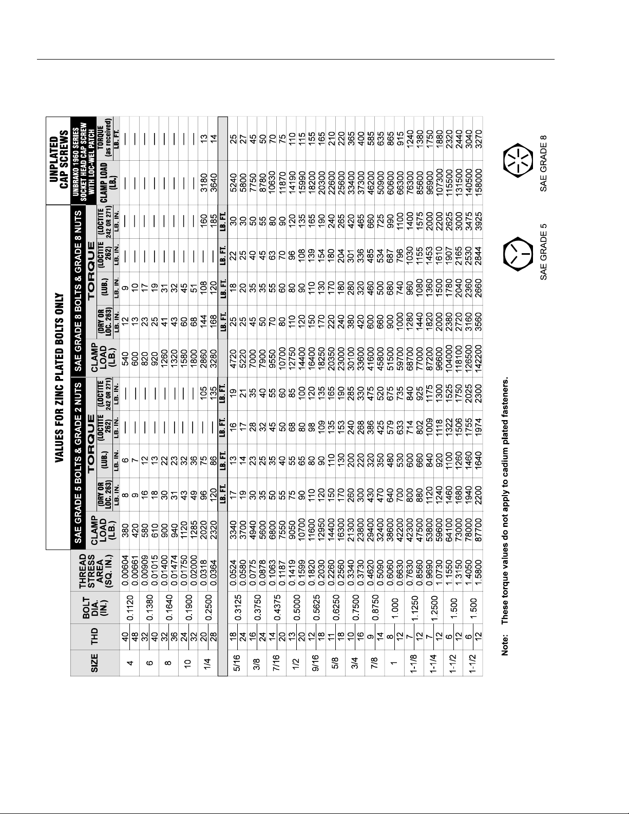
1-3. Torque Chart. (ANSI). . . . . . . . . . . . . . . . . . . . . . . . . . . . . . . . . . . . . . . . . . . . . . . . . . . . . . . . . . . .1-6
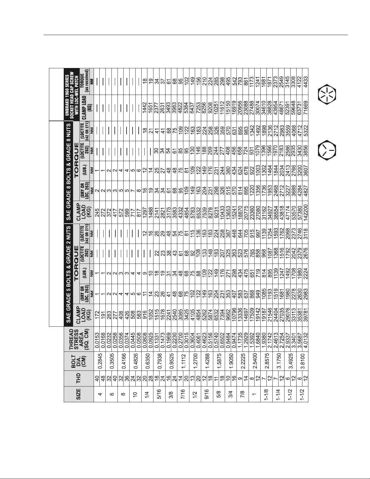
1-4. Torque Chart. (ANSI to METRIC Conversion) . . . . . . . . . . . . . . . . . . . . . . . . . . . . . . . . . . . . . . . .1-7
1-5. Torque Chart (Metric Class Fasteners). . . . . . . . . . . . . . . . . . . . . . . . . . . . . . . . . . . . . . . . . . . . . .1-8
2-1. Accessing Machine Underside Components by Lifting with a Fork Truck. . . . . . . . . . . . . . . . . . .2-8
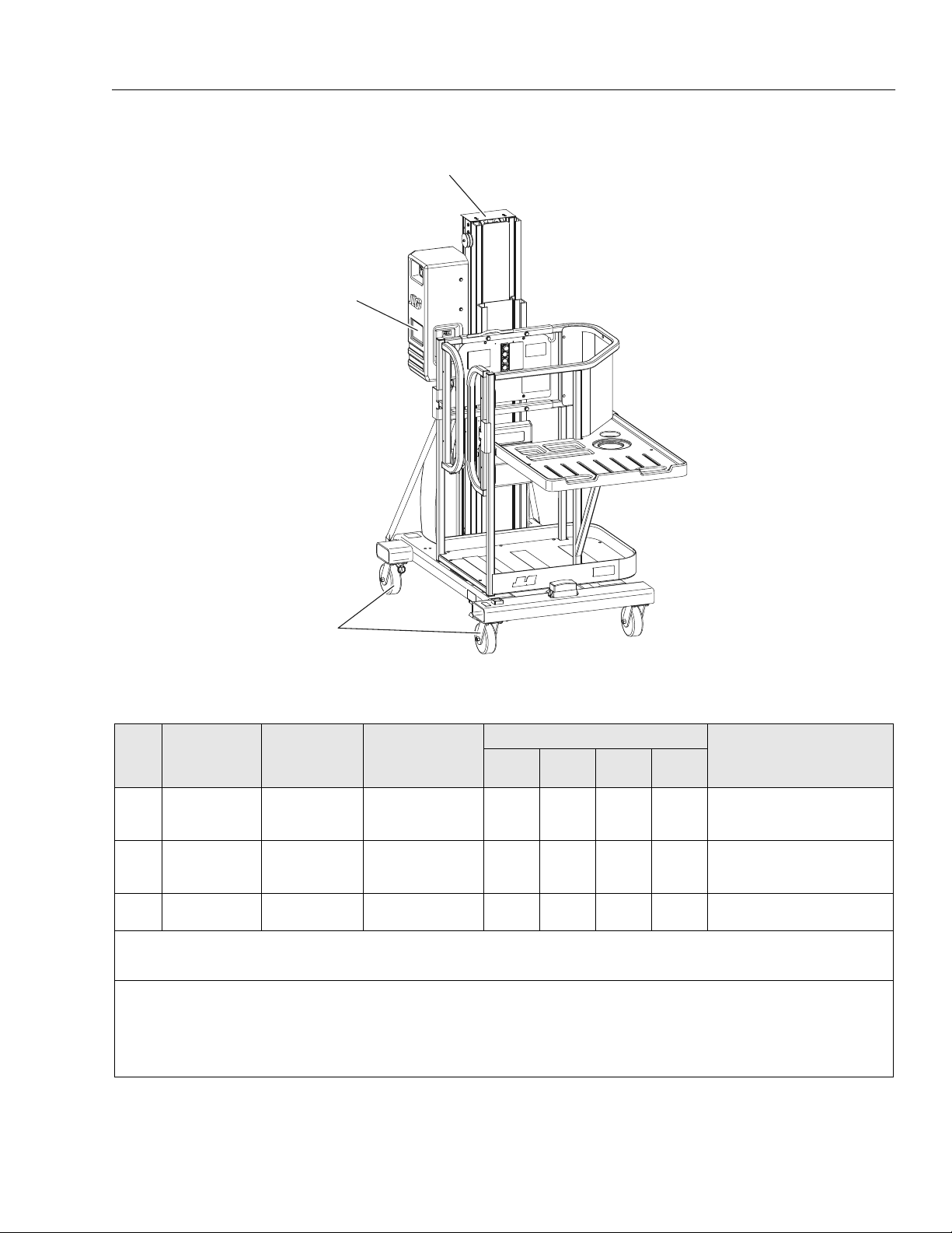
3-1. 9MP Base Components. . . . . . . . . . . . . . . . . . . . . . . . . . . . . . . . . . . . . . . . . . . . . . . . . . . . . . . . . . 3-1
4-1. Control Components Location - 9MP. . . . . . . . . . . . . . . . . . . . . . . . . . . . . . . . . . . . . . . . . . . . . . .4-1
4-2. 9MP - SCR Dual Voltage - Battery Charger Wiring Diagram. . . . . . . . . . . . . . . . . . . . . . . . . . . . . .4-14
5-1. Mast Components. (9MP) . . . . . . . . . . . . . . . . . . . . . . . . . . . . . . . . . . . . . . . . . . . . . . . . . . . . . . . .5-1
5-2. Mast Chain and Sequence Cable Adjustment Components. (9MP) . . . . . . . . . . . . . . . . . . . . . . .5-3
5-3. Machine Positioned for Cylinder Removal.. . . . . . . . . . . . . . . . . . . . . . . . . . . . . . . . . . . . . . . . . . .5-4
5-4. Lift Cylinder Component Cross-Section . . . . . . . . . . . . . . . . . . . . . . . . . . . . . . . . . . . . . . . . . . . . .5-7
5-5. Mast Section - Assembly Reference. . . . . . . . . . . . . . . . . . . . . . . . . . . . . . . . . . . . . . . . . . . . . . . .5-10
5-6. Mast Chain Routing Diagram. - 9MP. . . . . . . . . . . . . . . . . . . . . . . . . . . . . . . . . . . . . . . . . . . . . . . .5-12
5-7. Mast Bottom End - Slide Pad Installation (Typical) . . . . . . . . . . . . . . . . . . . . . . . . . . . . . . . . . . . . 5-13
5-8. Mast Top End - Slide Pad Installation (Typical) . . . . . . . . . . . . . . . . . . . . . . . . . . . . . . . . . . . . . . .5-13
3121163 – JLG Lift – iii
Page 8

TABLE OF CONTENTS
5-9. Platform Remove/Install - 9MP.. . . . . . . . . . . . . . . . . . . . . . . . . . . . . . . . . . . . . . . . . . . . . . . . . . . .5-18
6-1. Hydraulic Schematic. (9MP) (2792581-A) . . . . . . . . . . . . . . . . . . . . . . . . . . . . . . . . . . . . . . . . . . .6-3
6-2. Electrical Diagram. (9MP) (4933269-A) . . . . . . . . . . . . . . . . . . . . . . . . . . . . . . . . . . . . . . . . . . . . .6-4
LIST OF TABLES
TABLE NO. TITLE PAGE NO.
1-1 9MP - Machine Operating Specifications . . . . . . . . . . . . . . . . . . . . . . . . . . . . . . . . . . . . . . . . . . . .1-1
1-2. Hydraulic Oil Operating Range . . . . . . . . . . . . . . . . . . . . . . . . . . . . . . . . . . . . . . . . . . . . . . . . . . . .1-2
1-3. Lubrication Specifications . . . . . . . . . . . . . . . . . . . . . . . . . . . . . . . . . . . . . . . . . . . . . . . . . . . . . . . .1-3
1-4. Cylinder Specifications . . . . . . . . . . . . . . . . . . . . . . . . . . . . . . . . . . . . . . . . . . . . . . . . . . . . . . . . . .1-4
1-5 Lubrication Intervals for Various Components . . . . . . . . . . . . . . . . . . . . . . . . . . . . . . . . . . . . . . . .1-5
2-1 Inspection and Maintenance. . . . . . . . . . . . . . . . . . . . . . . . . . . . . . . . . . . . . . . . . . . . . . . . . . . . . .2-2
2-2 9MP - Preventive Maintenance & Inspection Schedule. . . . . . . . . . . . . . . . . . . . . . . . . . . . . . . . . . 2-3
2-3 Chain Stretch Tolerance . . . . . . . . . . . . . . . . . . . . . . . . . . . . . . . . . . . . . . . . . . . . . . . . . . . . . . . . . 2-6
5-1 9MP Mast Component Features . . . . . . . . . . . . . . . . . . . . . . . . . . . . . . . . . . . . . . . . . . . . . . . . . . .5-10
6-1. 9MP - Troubleshooting. . . . . . . . . . . . . . . . . . . . . . . . . . . . . . . . . . . . . . . . . . . . . . . . . . . . . . . . . .6-2
iv – JLG Lift – 3121163
Page 9
SECTION 1 - MACHINE SPECIFICATIONS
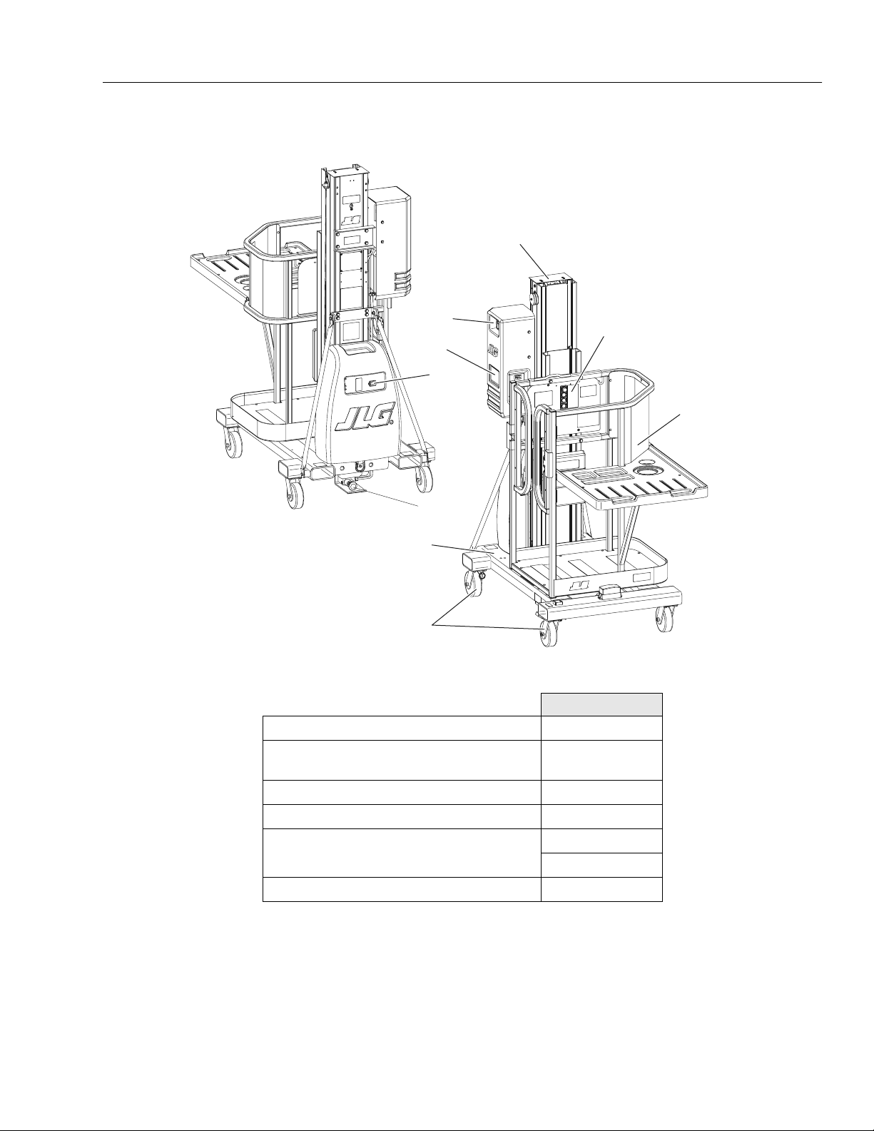
SECTION 1. MACHINE SPECIFICATIONS
7
6
5
4
3
2
1
Table 1-1. 9MP - Machine Operating Specifications
9MP
Maximum Occupants: 1
Maximum Work Load (Capacity):
(Platform + M aterial Tray)
500 lb. (227 kg)
(250 lb./250 lb.)
8
9
Machine Height (Platform Stowed) 77 in. (196cm)
Maximum Vertical Platform Height: 9 ft. (2.74 m)
M a x . P l a t f o r m S p e e d s (w / M a x . L oa d ) : P l a t f or m U p :
Pl a tf o r m D o wn :
Gross Machine Weight (Platform Empty):
16 sec.
8 - 13 sec.
740 lb. (336kg)
3121163 – JLG Lift – 1-1
Page 10

SECTION 1 - MACHINE SPECIFICATIONS
1.1 CAPACITIES
System Voltage
12 Volt DC
Hydraulic System
5 qts. U.S. (4.7 L)
1.2 COMPONENT DATA
Hydraulic Pump/Pump Motor Assembly
Pump Motor - 12 Volt DC I-Term Motor
Pump Displacement – 2.1cc/rev.
Pump Output –1.85 GPM (min.) @ 1300 PSI / 185 Amps
(max.) current draw using 200 SSU
(43cST) fluid
Reservoir Capacity – 1 Gallon (3.78 L)
Batteries/Battery Charger
Battery – 12 Volt
100 O. A. H.
Leak Proof/Valve Regulated
Type M2 Marine Combination
Battery Charger –
120 - 240 Volt A.C. Selectable -50/60 Hz input
C.E. Approved
12 volt, 20 amp output - with 2 amp finish
Microprocessor Controlled
SCR Circuit Monitor
AC and DC Reset Circuit Breakers
Automatic Charge Circuit
NOTE: The batteries on 9MP machines require approxi-
mately five (5) hours to fully charge when drained to
LOW BATTERY VOLTAGE on the Charger’s - Battery
Discharge Indicator.
1.3 PERFORMANCE DATA
Platform Capacity
500 lb. (227kg) - Maximum Capacity - (Combined
Platform + Tray Load)
250 lb. (113kg) - Maximum Material Tray Capacity
NOTE: Operator + Material Tray load combined, must not
exceed maximum platform capacity.
Platform and Material Tray Size
Platform - 28.5 in. W x 23 in. L (72cm) x (59cm)
Tray - 25.5 in. W x 23 in. L (65cm) x (59cm)
Machine Height (platform stowed)
77 in. (196cm) height
Base Footprint
34 in.-W x 50 in.-L (86cm) x (127cm)
1.4 TORQUE REQUIREMENTS
When maintenance becomes necessary or a fastener has
loosened, refer to the applicable Torque Chart later in this
section of the manual, to determine proper torque values.
1.5 LUBRICATION
Hydraulic Oil
Hydraulic oils must have anti-wear qualities at least to API
Service Classification GL-3, and sufficient chemical stability for mobile hydraulic system service. JLG Industries,
recommends Mobilfluid 424 hydraulic oil, which has an
SAE viscosity of 10W-30 and a viscosity index of 152.
For cold weather applications, i.e. when temperatures
remain consistently below +20°F (–7°C) JLG recom-
mends using Mobil DTE 13 hydraulic oil.
Aside from JLG recommendations, it is not advisable to
mix oils of different brands or types, as they may not contain the same required additives or be of comparable viscosities. If use of hydraulic oil other than Mobilfluid 424 is
desired, contact JLG Industries for proper recommendations.
Table 1-2. Hydraulic Oil Operating Range
HYDRAULIC SYSTEM OPERATING
TEMPERATURE RANGE
0 ° F t o +2 3 ° F
(-18° C to -5° C)
SAE VISCOSITY
GRADE
10W
1-2 – JLG Lift – 3121163
Page 11
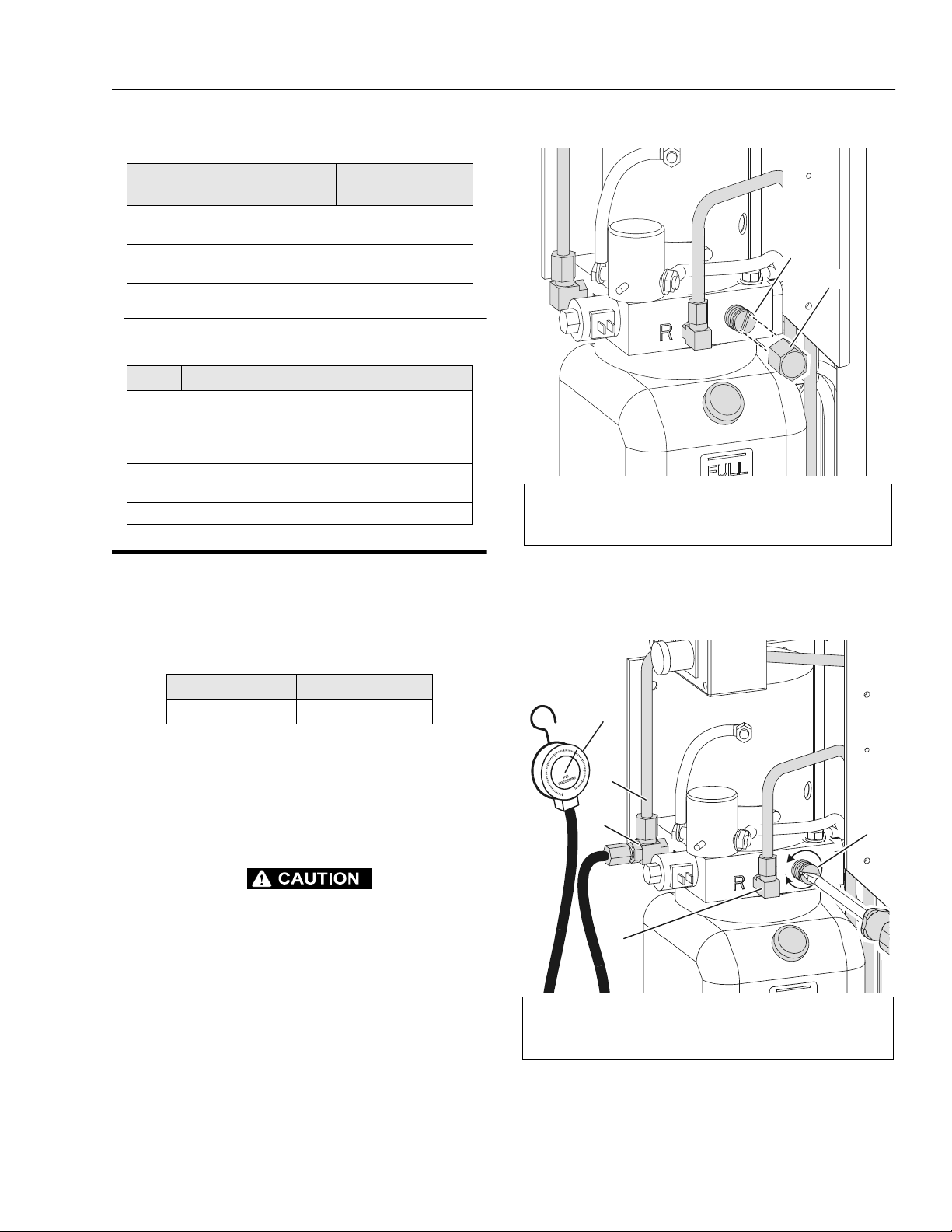
Table 1-2. Hydraulic Oil Operating Range
SECTION 1 - MACHINE SPECIFICATIONS
HYDRAULIC SYSTEM OPERATING
TEMPERATURE RANGE
0° F to +210° F
(-18° C t o + 9 9° C)
50° F to 2 10 ° F
(+10° C to + 21 0 ° C)
SAE VISCOSITY
GRADE
10W-20, 10W-30
20W-20
Lubrication Specifications
Table 1-3. Lubrication Specifications
KEY SPECIFICATIONS
MPG - Multipurpose Grease having a minimum dripping point
of 350° F. Excellent w ater resistance and adhesiv e qualities, and being of extreme pressure type. (Timken OK
40 pounds minimum.)
EPGL - Extreme Pressure Gear Lube (oil) meeting API service
classification GL-5 or MIL-Spec MIL-L-2105.
HO - Hydraulic Oil. ISO-Vg grade 32, 46.
1.6 HYDRAULIC PRESSURE ADJUSTMENT
Adjust system pressure so that platform will raise with
maximum rated capacity in platform.
The following pressure is a factory recommended (initial)
pressure settings;
2
1
1. Remove Adjust Screw Cap 2. Pressure Adjustment Screw
Note: Ground Control S tation cover has been removed.
Figure 1-1. Hydraulic Pressure Adjustment -
Cap and Screw
MODEL PRESSURE SETTING
9MP 1300 PSI
Turning adjustment screw clockwise increases system
pressure, turning screw counterclockwise decreases
system pressure.
Perform pressure adjustment with oil at normal operating
temperature. If pressure is set when oil is cold, platform
may not raise rated load after oil has warmed.
OPEN HYDRAULIC SYSTEM LINES ONLY WITH THE MAST FULLY
LOWERED TO RELIEVE PRESSURE IN THE SYSTEM. CAREFULLY
LOOSEN REQUIRED FITTINGS, WEAR SAFETY PROTECTION
EQUIPMENT WHEN WORKING WITH HYDRAULIC SYSTEMS.
Connect pressure gauge as shown in Figure 1-2., Typical
Hydraulic Pressure Gauge Installation. Select a T-Fitting to
exactly match the thread size of the pump pressure line
and gauge fitting as required.
1
2
3
4
1. Pressure Gauge Assembly 4. Retu rn Lin e
2. Extend Line 5. Pressure Adjust Screw
3. Tee Fitting
Figure 1-2. Typical Hydraulic Pressure Gauge
Installation.
5
3121163 – JLG Lift – 1-3
Page 12
SECTION 1 - MACHINE SPECIFICATIONS
1.7 CYLINDER SPECIFICATIONS
NOTE: All dimensions are given in inches (in), with the met-
ric equivalent, centimeters (cm), given in parentheses.
Table 1-4. Cylinder Specifications
DESCRIPTION
9MP
Lift Cylinder
BORE
in./(cm)
1.63
(4.10)
STROKE
in./(cm)
47.50
(120.65)
ROD DIA.
in./(cm)
1.375
(3.49)
1.8 SERIAL NUMBER LOCATIONS
For machine identification, a serial number plate is affixed
to the machine. The plate is located on the back of the
mast, just above the mast support column.
1-4 – JLG Lift – 3121163
Page 13
SECTION 1 - MACHINE SPECIFICATIONS
3
2
1
Lubrication Points
Table 1-5.Lubrication Intervals for Various Components
ITEM COMPONENT
1 Swivel Raceways
2
Hydraulic Oil
3
Mast Chains
Key to Lubricants: MPG - Multipurpose Grease
Notes: 1. Be cer tain to lubricate like items on each side of the machine.
2. Recommended lubricating intervals are based on nor mal use. If machine is subjected to severe operating conditions,
such as a high number of cycles, location, corrosive/dir ty environment, etc., user must adjust lubricating requirements accordingly.
3. Prior to checking hydraulic oil level, operate machine through one complete cycle of lift function (full up and down). Failure t o d o s o wi l l
result in incorrect oil level reading on the hydraulic reservoir.
(3)
(2)
HO - Hydrauli c Oil - See Section 1. 5, "Lubrication" in S ervice Manual.
NO/TYPE
LUBE POINTS
2 - Front Casters
2 - Rear Casters -
(if equipped)
F il l To Li n e o n
Reservoir
4 Qt. Reservoir
2 - Per Section
LUBE/METHOD
MONTHS6MONTHS1YEAR2YEARS
MPG - Pressure Gun
HO - Check Hyd. Oil
L e ve l
HO - Change Hyd. Oil
Chain Lube - Brush or
Spray
INTERVAL HOURS
3
✔
✔
COMMENTS
Check Hydraulic Oil level daily.
Change Hydr aulic Oil every 2
✔
years.
Inspect, lubricate if dry or rusting.
3121163 – JLG Lift – 1-5
Page 14
SECTION 1 - MACHINE SPECIFICATIONS
Figure 1-3. Torque Chart. (ANSI)
1-6 – JLG Lift – 3121163
Page 15
SECTION 1 - MACHINE SPECIFICATIONS
S
G
5S
G
8
RADE
UNPLATED
CAP SCREWS
AE
RADE
AE
VALUES FOR ZINC PLATED BOLTS ONLY
Note: These torque values do not apply to cadium plated fasteners.
Figure 1-4. Torque Chart. (ANSI to METRIC Conversion)
3121163 – JLG Lift – 1-7
Page 16
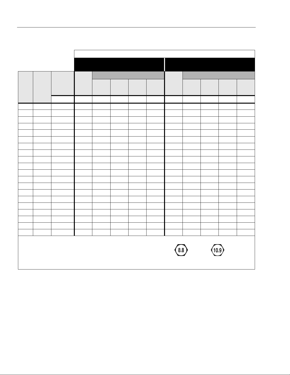
SECTION 1 - MACHINE SPECIFICATIONS
9
VALUES FOR ZINC PLATED / YELLOW CHROMATE FASTENERS ONLY
CLASS 8.8 METRIC BOLTS &
CLASS 8 METRIC NUTS
TORQUE
LUB
LOCTITE
262
LOCTITE
242 OR
271
SIZE PITCH
TENSILE
STRESS
AREA
CLAMP
LOAD
DRY OR
LOCTITE
263
sq. mm KN N, m N, m N, m N, m KN N, m N, m N, m N, m
3 .5 5.03 2.19 1.3 1.0 1.2 1.4 3.13 1.9 1.4 1.5 2.1
3.5 .6 6.78 2.95 2.1 1.6 1.9 2.3 4.22 3.0 2.2 2.4 3.3
4 .7 8.78 3.82 3.1 2.3 2.8 3.4 5.47 4.4 3.3 3.5 4.8
5 .8 14.2 6.18 6.2 4.6 5.6 6.8 8.85 8.9 6.6 7.1 9.7
6 1 20.1 8.74 11 7.9 9.4 12 12.5 15 11 12 17
7 1 28.9 12.6 18 13 16 19 18 25 19 20 28
81.2536.615.92519232822.837272940
10 1.5 58.0 25.2 50 38 45 55 36.1 72 54 58 79
12 1.75 84.3 36.7 88 66 79 97 52.5 126 95 101 139
14 2 115 50.0 140 105 126 154 71.6 200 150 160 220
16 2 157 68.3 219 164 197 241 97.8 313 235 250 344
18 2.5 192 83.5 301 226 271 331 119.5 430 323 344 473
20 2.5 245 106.5 426 320 383 469 152.5 610 458 488 671
22 2.5 303 132.0 581 436 523 639 189.0 832 624 665 915
24 3 353 153.5 737 553 663 811 220.0 1060 792 845 1170
27 3 459 199.5 1080 810 970 1130 286.0 1540 1160 1240 1690
30 3.5 561 244.0 1460 1100 1320 1530 349.5 2100 1570 1680 2310
33 3.5 694 302.0 1990 1490 1790 2090 432.5 2600 2140 2280 2860
36 4 817 355.0 2560 1920 2300 2690 509.0 3660 2750 2930 4020
42 4.5 1120 487.0 4090 3070 3680 4290 698.0 5860 4400 4690 6440
CLASS 10.9 METRIC BOLTS &
CLASS 10 METRIC NUTS
CLAMP
LOAD
DRY OR
LOCTITE
263
TORQUE
LUB
LOCTITE
262
LOCTITE
242 OR
271
Note: These torque values do not apply to cadmium plated fasteners.
METRIC CLASS 8.8METRIC CLASS 10.
Figure 1-5. Torque Chart (Metric Class Fasteners)
1-8 – JLG Lift – 3121163
Page 17

SECTION 2. GENERAL
SECTION 2 - GENERAL
2.1 MACHINE PREPARATION, INSPECTION, AND MAINTENANCE
General
This section provides the necessary information needed
by those personnel that are responsible to place the
machine in operation readiness and maintain its safe
operating condition. For maximum service life and safe
operation, ensure that all the necessary inspections and
maintenance have been completed before placing the
machine into service.
Preparation, Inspection, and Maintenance
It is important to establish and conform to a comprehensive inspection and preventive maintenance program.
The following table outlines the periodic machine inspections and maintenance recommended by JLG Industries,
Inc. Consult your national, regional, or local regulations
for further requirements for aerial work platforms. The frequency of inspections and maintenance must be
increased as environment, severity and frequency of
usage requires.
Pre-Start Inspection
It is the User’s or Operator’s primary responsibility to perform a Pre-Start Inspection of the machine prior to use
daily or at each change of operator. Reference the Operator’s and Safety Manual for completion procedures for the
Pre-Start Inspection. The Operator and Safety Manual
must be read in its entirety and understood prior to performing the Pre-Start Inspection.
Pre-Delivery Inspection and Frequent Inspection
The Pre-Delivery Inspection and Frequent Inspection shall
be performed by a qualified JLG equipment mechanic.
JLG Industries, Inc. recognizes a qualified JLG equipment
mechanic as a person who, by possession of a recognized degree, certificate, extensive knowledge, training, or
experience, has successfully demonstrated the ability and
proficiency to service, repair, and maintain the subject
JLG product model.
The Pre-Delivery Inspection and Frequent Inspection procedures are performed in the same manner, but at different times. The Pre-Delivery Inspection shall be performed
prior to each sale, lease, or rental delivery. The Frequent
Inspection shall be accomplished for each machine in service for 3 months; out of service for a period of more than
3 months; or when purchased used. The frequency of this
inspection must be increased as environment, severity
and frequency of usage requires.
Reference the JLG Pre-Delivery and Frequent Inspection
Form and the Inspection and Preventative Maintenance
Schedule for items requiring inspection during the performance of these inspections. Reference the appropriate
areas of this manual for servicing and maintenance procedures.
Annual Machine Inspection
JLG recommends that an Annual Machine Inspection be
performed by a Factory-Certified Service Technician on an
annual basis, no later than thirteen (13) months from the
date of the prior Annual Machine Inspection. JLG Industries, Inc. recognizes a Factory-Certified Service Technician as a person who has successfully completed the JLG
Service Training School for the subject JLG product
model. Reference the machine Service and Maintenance
Manual and appropriate JLG inspection form for performance of this inspection.
Reference the JLG Annual Machine Inspection Form and
the Inspection and Preventative Maintenance Schedule for
items requiring inspection during the performance of this
inspection. Reference the appropriate areas of this manual for servicing and maintenance procedures.
For the purpose of receiving safety-related bulletins, it is
important that JLG Industries, Inc. has updated ownership
information for each machine. When performing each
Annual Machine Inspection, notify JLG Industries, Inc. of
the current machine ownership.
Preventative Maintenance
In conjunction with the specified inspections, maintenance shall be performed by a qualified JLG equipment
mechanic. JLG Industries, Inc. recognizes a qualified JLG
equipment mechanic as a person who, by possession of a
recognized degree, certificate, extensive knowledge, training, or experience, has successfully demonstrated the
ability and proficiency to service, repair, and maintain the
subject JLG product model.
Reference Table 2-2, 9MP - Preventive Maintenance &
Inspection Schedule., and the appropriate areas of this
manual for servicing and maintenance procedures. The
frequency of service and maintenance must be increased
as environment, severity and frequency of usage requires.
3121163 – JLG Lift – 2-1
Page 18

SECTION 2 - GENERAL
Table 2-1. Inspection and Maintenance
Type Frequency
Pre-Start
Inspection
Pre-Delivery
Inspection
Frequent
Inspection
Annual
Machine
Inspection
Preventative
Maintenance
Prior to use each day; or
At each Operator change .
Prior to each sale, lease, or
rental delivery.
In service for 3 months; o r Out of service for
a period of more than 3 months; or Purchased used.
Annually, no later than 13 months from the
date of the prior inspe ction.
At intervals as specifi ed in the Service and
Maintenance Manual.
Primary
Responsibility
User or Operator Us er or Operator Operator and Safety M anual
Owner, Dealer, or User Qualified JLG
Owner, Dealer, or User Qualified JLG
Owner, Dealer, or User Qualified JLG
Owner, Dealer, or User Qualified JLG
Service
Qualification
Mechanic
Mechanic
Mechanic
Mechanic
Reference
Service and Maintenance Man ual
and applicable JLG in spection
form.
Service and Maintenance Man ual
and applicable JLG in spection
form.
Service and Maintenance Man ual
and applicable JLG in spection
form.
Service and Mai ntenance Manual
2.2 PREVENTIVE MAINTENANCE AND INSPECTION SCHEDULE
(See Table 2-2.)
The preventive maintenance and inspection checks are
listed and defined in the following table. This table is
divided into two basic parts, the “AREA” to be inspected
and the “INTERVAL” at which the inspection is to take
place. Under the “AREA” portion of the table, the various
systems along with the components that make up that
system are listed. The “INTERVAL” portion of the table is
divided into five columns representing the various inspection time periods. The numbers listed within the interval
column represent the applicable inspection code for
which that component is to be checked.
The checks and services listed in this schedule are not
intended to replace any local or regional regulations that
may pertain to this type of equipment nor should the lists
be considered as all inclusive. Variances in interval times
may occur due to climate and/or conditions and depending on the location and use of the machine.
2-2 – JLG Lift – 3121163
Page 19

SECTION 2 - GENERAL
Table 2-2. 9MP - Preventive Maintenance & Inspection Schedule.
INTERVAL
AREA ON MACHINE
PRE-START (1)
INSPECTION
3 MONTH
PREVENTATIVE
MAINTENANCE
MAST ASSEMBLY 7
Mast Sections 2, 5 2, 5
Chain Systems 14 3, 14 14, 25
Sequence Cable Systems 31, 2, 3
Covers or Shields 1
Sheave Systems 1, 2 1, 2
Bearings 1, 2
Slide Pads 1, 2
PLATFORM ASSEMBLY 7
Platform and Material Tray 11
Guard Rails 1, 2, 4 1, 2, 4
Gate 1, 5 1, 5
Floor 1, 2 1, 2
Lanyard Anchorage Point 1, 4 1, 4
CHASSIS ASSE MBLY 7
Front (and Rear, if equipped) Ca ster Wheels 1, 2 14 1, 2 1, 2
Rear Wheel Assembl y 22
Bubble Level 1, 7 1, 7
Floor Stop Assembly 1, 3, 7
FUNCTIONS/CONTROLS 7
Platform Cont rols 5, 6, 7 5, 6, 7
Ground Controls 5, 6 5, 6, 14
Function Control Locks, Guards, or Detents 5 5
Function Enable Syste m
Emergency Stop Swit ches (Ground & Platform) 5
Function Limit or C utout Switch Systems 5
Manual Descent or Aux iliary Power 5 5
POWER SYSTEM
Battery 19 9 18
Battery Charger 5
HYDRAULIC/ELECTRIC SYS TEM 9
Hydraulic Pump 1, 2, 9 1, 2, 5, 9
Hydraulic Cylind er 2, 7, 9 2, 9
Cylinder Attachment Pins and Pin Retainers 1, 2 1, 2
Hydraulic Hoses, Li nes, and Fittings 1, 9 1, 9
Hydraulic Reservoir, Cap, and Breather 5, 7 5, 7
Hydraulic Filter
Hydraulic Fluid * 11 11 11
Electrical Connections 20 20
Instruments, Gauges, S witches, Lights, Horn 5
6 MONTH
PREVENTATIVE
MAINTENANCE
PRE-DELIVERY (2)
OR FREQUENT (3)
INSPECTION
ANNUAL (4)
(YEARLY)
INSPECTION
3121163 – JLG Lift – 2-3
Page 20

SECTION 2 - GENERAL
Table 2-2. 9MP - Preventive Maintenance & Inspection Schedule.
INTERVAL
AREA ON MACHINE
PRE-START (1)
INSPECTION
3 MONTH
PREVENTATIVE
MAINTENANCE
GENERAL
Operator and Safety Manua ls in Storage Box 21 21 21
ANSI and EMI Manuals/Handbooks Install ed 21 21 21
Capacity Decals Ins talled, Secure, Legible 21 21 21
All Decals/Placards Installed, Secure, Legible 21 21 21
"Walk-Around" Inspection Performe d 22
Annual Machine Inspecti on Due 21
No Unauthorized Modificatio ns or Additions 21 21
All Relevant Safety Publ ications Incorporated 21 21, 22
General Structural C ondition and Welds 2, 4 2, 4
All Fasteners, Pins , Shields, and Covers 1, 2
Grease and Lubricate to Specificat ions 22 22
Function Test of All Systems 22 22
Paint and Appearance 77
Stamp Inspection Da te on Frame 22
Notify JLG of Machine Ownershi p 22
* Drain and Refill w ith fresh hydraulic fluid every two years.
6 MONTH
PREVENTATIVE
MAINTENANCE
PRE-DELIVERY (2)
OR FREQUENT (3)
INSPECTION
ANNUAL (4)
(YEARLY)
INSPECTION
Footnotes:
(1) Prior to use each day; or at each Operator change
(2) Prior to each sale, lease, or delivery
(3) In service for 3 months; or Out of service for 3 months
or more; or Purchased used
(4) Annually, no later than 13 months from the date of the
prior inspection
Inspection and Maintenance Codes:
1. Check for proper and secure installation.
2. Visual inspection for damage, cracks, distortion, or
excessive wear.
3. Check for proper adjustment.
4. Check for cracked or broken welds.
5. Operates properly.
6. Returns to neutral or "off" position when released.
7. Clean and free of debris.
8. Interlocks function properly.
9. Check for signs of leakage.
10. Decals installed and legible.
11. Check for proper fluid level.
12. Check for chafing and proper routing.
13. Check for proper tolerances.
14. Properly lubricated.
15. Torqued to proper specification.
16. No gouges, excessive wear, or cords showing.
17. Properly inflated and seated around rim.
18. Proper and authorized components.
19. Fully charged.
20. No loose connections, corrosion, or abrasions.
21. Verify.
22. Perform.
23. Sealed properly.
24. Overrides Platform controls.
25. Inspected per Service and Maintenance Manual.
2-4 – JLG Lift – 3121163
Page 21
SECTION 2 - GENERAL
2.3 SERVICING AND MAINTENANCE GUIDELINES
General
The following information is provided to assist you in the
use and application of servicing and maintenance procedures contained in this chapter.
Safety and Workmanship
Your safety, and that of others, is the first consideration
when engaging in the maintenance of equipment. Always
be conscious of component weight. Never attempt to
move heavy parts without the aid of a mechanical device.
Do not allow heavy objects to rest in an unstable position.
When raising a portion of the equipment, ensure that adequate support is provided.
NEVER WORK UNDER AN ELEVATED PLATFORM UNTIL PLATFORM HAS BEEN SAFELY RESTRAINED FROM ANY MOVEMENT
BY BLOCKING OR OVERHEAD SLING.
Cleanliness
The most important single item in preserving the long service life of a machine is to keep dirt and foreign materials
out of the vital components. Precautions have been taken
to safeguard against this. Shields, covers, seals, and filters are provided to keep the wheel bearings, mast sections and oil supply clean; however, these items must be
maintained on a scheduled basis in order to function
properly.
At any time when oil lines are disconnected, clear adjacent areas as well as the openings and fittings themselves. As soon as a line or component is disconnected,
cap or cover all openings to prevent entry of foreign matter.
Clean and inspect all parts during servicing or maintenance, and assure that all passages and openings are
unobstructed. Cover all parts to keep them clean. Be sure
all parts are clean before they are installed. New parts
should remain in their containers until they are ready to be
used.
Components Removal and Installation
Use adjustable lifting devices, whenever possible, if
mechanical assistance is required. All slings (chains,
cables, etc.) should be parallel to each other and as near
perpendicular as possible to top of part being lifted.
Should it be necessary to remove a component on an
angle, keep in mind that the capacity of an eyebolt or similar bracket lessens, as the angle between the supporting
structure and the component becomes less than 90
degrees.
If a part resists removal, check to see whether all nuts,
bolts, cables, brackets, wiring, etc., have been removed
and that no adjacent parts are interfering.
Component Disassembly and Reassembly
When disassembling or reassembling a component, complete the procedural steps in sequence. Do not partially
disassemble or assemble one part, then start on another.
Always recheck your work to assure that nothing has been
overlooked. Do not make any adjustments, other than
those recommended, without obtaining proper approval.
Pressure-Fit Parts
When assembling pressure-fit parts, use an “anti-seize” or
molybdenum disulfide base compound to lubricate the
mating surface.
Bearings
When a bearing is removed, cover it to keep out dirt and
abrasives. Clean bearings in nonflammable cleaning solvent and allow to drip dry. Compressed air can be used
but do not spin the bearing.
Discard bearings if the races and balls (or rollers) are pitted, scored, or burned.
If bearing is found to be serviceable, apply a light coat of
oil and wrap it in clean (waxed) paper. Do not unwrap
reusable or new bearings until they are ready to install.
Lubricate new or used serviceable bearings before installation. When pressing a bearing into a retainer or bore,
apply pressure to the outer race. If the bearing is to be
installed on a shaft, apply pressure to the inner race.
Gaskets
Check that holes in gaskets align with openings in the
mating parts. If it becomes necessary to hand-fabricate a
gasket, use gasket material or stock of equivalent material
and thickness. Be sure to cut holes in the right location, as
blank gaskets can cause serious system damage.
Bolt Usage and Torque Application
Use bolts of proper length. A bolt which is too long will
bottom before the head is tight against its related part. If a
bolt is too short, there will not be enough thread area to
engage and hold the part properly. When replacing bolts,
use only those having the same specifications of the original, or one which is equivalent.
Unless specific torque requirements are given within the
text, standard torque values should be used on heattreated bolts, studs, and steel nuts, in accordance with
recommended shop practices. (See Torque Charts in Sec-
tion-1.)
3121163 – JLG Lift – 2-5
Page 22

SECTION 2 - GENERAL
Hydraulic Lines and Electrical Wiring
Clearly mark or tag hydraulic lines and electrical wiring, as
well as their receptacles, when disconnecting or removing
them from the unit. This will assure that they are correctly
reinstalled.
Hydraulic System
Keep the system clean. If evidence of metal or rubber particles is found in the hydraulic system, drain and flush the
entire system.
Disassemble and reassemble parts on clean work surface. Clean all metal parts with non-flammable cleaning
solvent. Lubricate components, as required, to aid assembly.
Lubrication and Servicing
Components and assemblies requiring lubrication and
servicing are shown in the Lubrication Chart, (See Figure
1-2.). Service applicable components with the amount,
type, and grade of lubricant recommended in this manual,
at the specified intervals. When recommended lubricants
are not available, consult your local supplier for an equivalent that meets or exceeds the specifications listed.
Batteries
Clean batteries, using a non-metallic brush and a solution
of baking soda and water. Rinse with clean water. After
cleaning, thoroughly dry batteries and coat terminals with
an anti-corrosion compound.
Mast Chain Inspection Procedure
MAST CHAINS TO BE INSPECTED AND LUBRICATED EVERY
THREE MONTHS.
Inspect mast chains for the following conditions:
Wear: Always inspect that segment of chain that operates
over a sheave. As the chain flexes over the sheaves, joints
and plate edges very gradually wear. Chain “stretch” can
be measured using a manufacturers wear scale or steel
tape. When chains have elongated 3% they must be
removed and replaced. Refer to Table 2-3 for proper chain
specifications and allowable stretch tolerances. Peening
and wear of chain plate edges are caused by sliding over
a chain worn contact face of a sheave, or unusually heavy
loads. All of the above require replacement of the chain
and correction of the cause. Chain side wear, noticeable
when pin heads and outside plates show a definite wear
pattern, is caused by misalignment of the sheave/chain
anchors and must be corrected promptly. Do not repair
chains; if a section of chain is damaged, replace the entire
chain set.
Rust and Corrosion: Rust and corrosion will cause a
major reduction in the load carrying capacity of the chain,
because these are primary reasons for side plate cracking. The initial lubrication at the factory is applied in a hot
dip tank to assure full penetration into the joint. Do not
steam clean or degrease chains. At time of chain installation, factory lube must be supplemented by a maintenance program to provide a film of oil on the chains at all
times. If chains are corroded, they must be inspected,
especially the outside plates, for cracks in-line with the
pins. If cracks are found, replace the chain; if no cracks
are discovered, lubricate the chains by dipping in heated
oil, and reinstall on the machine. Keep chains lubricated.
Table 2-3. Chain Stretch Tolerance
Chain Size
.50" pitch 12" or 24 pitches .24 in./12 in. span
.625 pitch 15" or 24 pitches .30 in./15 in. span
Fatigue Cracks: Fatigue is a phenomenon that affects
most metals, and is the most common cause of chain
plate failures. Fatigue cracks are found through the link
holes, perpendicular (90 degrees) from the pin in-line
position. Inspect chains carefully after long time use and
heavy loading for this type of crack. If any cracks are discovered, replace all chains, as seemingly sound plates
are on the verge of cracking. Fatigue and ultimate
strength failures on JLG Lifts are incurred as a result of
severe abuse as design specs are well within the rated lifting capacity of these chains.
Tight Joints: All joints in the leaf chain should flex freely.
On leaf chain, tight joints are usually caused by rust/corrosion, or the inside plates “walking” off the bushing. Limber
up rusty/corroded chains (after inspecting carefully) with a
heavy application of oil (preferably a hot oil dip). Tap
inside “walking” plates inward; if “walking” persists,
replace the chain. This type of problem is accelerated by
poor lubrication maintenance practice, and most tight
joint chains have been operated with little or no lubrication. Tight joints on leaf chain are generally caused by:
a. Bent pins or plates.
b. Rusty joints.
c. Peened plate edges.
Oil rusty chains, and replace chains with bent or peened
chain components. Keep chains lubricated.
Protruding or Turned Pins: Chains operating with inadequate lube generate tremendous friction between the pin
and plates (pin and bushing on leaf chain). In extreme
cases, this frictional torque can actually turn the pins in
the outside press-fit plates. Inspect for turned pins, which
can be easily spotted as the “V” flats on the pin heads are
no longer in line. Replace all chains showing evidence of
turned or protruding pins. Keep chains lubricated.
Pin to Pin
Measurement
Allowable Stretch
2-6 – JLG Lift – 3121163
Page 23

SECTION 2 - GENERAL
Chain Anchors and Sheaves: An inspection of the chain
must include a close examination of chain anchors and
sheaves. Check chain anchors for wear breakage and
misalignment. Anchors with worn or broken fingers should
be replaced. They should also be adjusted to eliminate
twisting the chain for an even load distribution.
Inspect the sheaves, sheave bearings, sheave grooves
and pins for extreme wear, replace as necessary. A worn
sheave can mean several problems, as follows:
a. Chains too tight.
b. Sheave bearings/pin bad.
c. Bent/misaligned chains.
2.4 LUBRICATION INFORMATION
Hydraulic System
The primary enemy of a hydraulic system is contamination. Contaminants enter the system by various means,
e.g., using inadequate hydraulic oil, allowing moisture,
grease, filings, sealing components, sand, etc., to enter
when performing maintenance, or by permitting the pump
to cavitate due to insufficient system warm-up or leaks in
the pump supply.
The design and manufacturing tolerances of the component working parts are very close, therefore, even the
smallest amount of dirt or foreign matter entering a system
can cause wear or damage to the components and generally results in faulty operation. Every precaution must be
taken to keep hydraulic oil clean, including reserve oil in
storage.
Cloudy oils indicate a high moisture content which permits organic growth, resulting in oxidation or corrosion. If
this condition occurs, the system must be drained,
flushed, and refilled with clean oil.
It is not advisable to mix oils of different brands or types,
as they may not contain the same required additives or be
of comparable viscosities. Good grade mineral oils, with
viscosities suited to the ambient temperatures in which
the machine is operating, are recommended for use.
Hydraulic Oil
For best performance, JLG recommends the use of ISOVg grade 32, 46 oil with a viscosity range between 15-250
SUS at 100 degrees F (32-54 cST at 40 degrees C). Refer
to Section 1-5 of this Service Manual for recommended
hydraulic oils.
Changing Hydraulic Oil
Use of any of the recommended hydraulic oils eliminates
the need for changing the oil on a regular basis. If it is necessary to change the oil, use only those oils meeting or
exceeding the specifications appearing in this manual. If
unable to obtain the same type of oil supplied with the
machine, consult local supplier for assistance in selecting
the proper equivalent. Avoid mixing petroleum and synthetic base oils. JLG Industries recommends changing the
hydraulic oil annually.
Use every precaution to keep the hydraulic oil clean. If the
oil must be poured from the original container into
another, be sure to clean all possible contaminants from
the service container.
While the unit is shut down, a good preventive maintenance measure is to make a thorough inspection of all
hydraulic components, lines, fittings, etc., as well as a
functional check of each system, before placing the
machine back in service.
Lubrication Specifications
Specified lubricants, as recommended by the component
manufacturers, are always the best choice, however,
multi-purpose greases usually have the qualities which
meet a variety of single purpose grease requirements.
Should any question arise regarding the use of greases in
maintenance stock, consult your local supplier for evaluation. Refer to the Lubricant Table in Section-1 of this Service Manual for an explanation of the lubricant key
designations.
NOTE: Metal particles may appear in the oil of new
machines due to the wear-in of meshing components.
3121163 – JLG Lift – 2-7
Page 24

SECTION 2 - GENERAL
2.5 POSITIONING LIFT FOR ACCESS TO COMPONENTS LOCATED UNDER THE BASE FRAME
Access to the underside of the 9MP lift can be obtained by
lifting the machine with a fork lift truck, using the fork lift
pockets in the base frame.
Lifting with a Fork Truck (See Figure 2-1.)
1. Choose a fork lift truck capable of safely handling
the full weight of the machine.
2. Locate work area on a firm, level surface.
KEEP MACHINE LEVEL OR SLIGHTLY TILTED TOWARD FORKLIFT
TRUCK WHEN LIFTING TO PREVENT MACHINE FROM SLIDING
OFF LIFTING TINES.
3. When lifting with a fork truck, lift only using the fork
lift-truck pockets running the length of the machine’s
base frame from rear to front.
4. After lifting machine to desired work height, place
support stands under the machine. The support
stands must reach from the floor to the bottom of the
machine and be capable of safely handling the
weight of the machine.
1
2
1. Lift using onl y the fork lift pockets in the base frame.
2. Place suppor t stands between machine and floor.
Figure 2-1. Accessing Machine Underside
Components by Lifting with a Fork Truck.
2-8 – JLG Lift – 3121163
Page 25

SECTION 3. BASE COMPONENTS
8
3.1 BASE ASSEMBLY COMPONENTS
1
2
3
SECTION 3 - BASE COMPONENTS
6
4
7
5
6
7
1. Base Frame 4. Front Swivel Casters 7. Rear Locking Swivel Casters and Rear
2. Platform Descent Warning Beacon 5. Floor Stop Caster/Base Frame
3. Platform Descent Warning Alarm 6. Rear Straight Axle Wheels/Axle Frame 8. Mast Suppor t Assembly
Figure 3-1. 9MP Base Components.
3121163 – JLG Lift – 3-1
Page 26

SECTION 3 - BASE COMPONENTS
1
2
3
2
1
2
3
3.2 PLATFORM DESCENT - BEACON AND ALARM
Descent Beacon - Remove/Install
1. Beacon Assembly 3. Rout wires through hole in
2. Mounting Screws base frame
3.3 WHEEL ASSEMBLIES
Front Caster Wheel - Remove/Install
3
2
1
1. Caster Wheel Assembly 3. Base Frame (Front Member)
2. Hex Head Cap Screws
Note: Left front caster wheel shown.
Descent Alarm - Remove/Install
1. Descent Alarm Assembly 3. Wire Terminals
2. Mounting Screws
Note: Located inside base frame, under the platform.
Rear Locking Caster Wheel - Remove/Install
3
2
1
1. Rear Locking Caster Wheel 3. Base Frame Caster
2. Hex Head Cap Screws Mounting Pad
Note: Right rear locking caster shown.
3-2 – JLG Lift – 3121163
Page 27

SECTION 3 - BASE COMPONENTS
Rear Wheel (Straight Axle)- Remove/Install
5
4
3
2
1
1. Snap Ring 4. Washers (as required)
2. Washer 5. Base Frame Mounted Axle
3. Rear Wheel Assembly
Note: Left rear wheel shown.
3.4 FLOOR STOP ASSEMBLY
Floor Stop - Remove/Install
1. Floor Stop Assembly 5. Right Side Base Frame/
2. Hex Nuts Fork Lift Tube
3. Flat Washers 6. Hex Head Screws (b)
4. Interlock Switch Bracket (a) 7. Flat Washers
Note: (a) Mount bracket on outside of floor stop base.
(b) Apply Loctite #242 to screw threads before
installing nuts.
To gain access to the floor stop mounting screws located inside
the right base frame/fork lift tube:
a. On a firm, level surface, power machine ON.
b. Set floor stop.
c. Raise platform approximately 2 feet from outside the platform.
d. Power machine OFF.
e. Place a floor stand under the raised platform before working
under it.
f. Release the floor stop.
g. Remove floor stop fasteners.
3121163 – JLG Lift – 3-3
Page 28

SECTION 3 - BASE COMPONENTS
1
2
3
3
456
7
Floor Stop Interlock Switch Assembly Remove/Install
1. Floor Stop Interlock Switch 3. Hex Nuts and Flat Washers (a)
2. Switch Bracket
Note: (a) Apply Loctite #242 to screw threads before
installing nuts.
To gain access to the floor stop/interlock switch bracket mounting
screws located inside the right base frame/fork lift tube:
a. On a firm, level surface, power machine ON.
b. Set floor stop.
c. Raise platform approximately 2 feet from outside the platform.
d. Power machine OFF.
e. Place a floor stand under the raised platform before working
under it.
f. Release the floor stop.
g. Remove floor stop/interlock switch bracket fasteners.
Once installed, the floor stop pedal arm must engage the interlock
switch actuator button when the pedal is UP, this will open the lift
circuit. When the pedal is DOWN (SET), the pedal arm will pull
away from the switch and allow the button to release, closing the
circuit.
Floor Stop Interlock Switch - Remove/Install
1
2
1. Mounting Screws (a) 5. Flat Washers
2. Flat Washers 6. Lock Washers
3. Interlock Switch 7. Mounting Nuts
4. Switch Mounting Bracket
Note: (a) Apply Loctite #242 to screw threads before
installing nuts.
3-4 – JLG Lift – 3121163
Page 29

SECTION 3 - BASE COMPONENTS
1
2
1
3.5 BASE MAST SUPPORTS
Mast Support to Base - Straight Axle Base Remove/Install
3
4
1. Mast Support (left side shown) 3. Flat Washer
2. Hex Head Cap Screw 4. Nut (a)
Note: (a) Apply Loctite #242 to screw threads before
installing nut.
Mast Support to Base - Rear Caster Wheel Base - Remove/Install
3
2
1. Hex Head Cap Screw 3. Support Attach Lug
2. Mast Support (left side shown)
Note: (a) Apply Loctite #242 to screw threads before
installing.
3121163 – JLG Lift – 3-5
Page 30

SECTION 3 - BASE COMPONENTS
This page intentionally left blank.
3-6 – JLG Lift – 3121163
Page 31

SECTION 4. CONTROL COMPONENTS
675
4
4.1 CONTROL COMPONENTS OVERVIEW
SECTION 4 - CONTROL COMPONENTS
3
1
1. Rear Cover 4. Ground Control Station Cover 7. Platform Control Station
2. 12 Volt Sealed (AGM) Battery 5. Pump/Motor/Tank Assembly
3. Battery Charger 6. Ground Control Box Note: Machine shown without platform.
2
Figure 4-1. Control Components Location - 9MP.
3121163 – JLG Lift – 4-1
Page 32

SECTION 4 - CONTROL COMPONENTS
1
2
4
3
4.2 CONTROL COVER INSTALLATION
Battery/Battery Charger Cover - Remove/ Install
Ground Control Station Cover - Remove/ Install
1. Ground Station Cover 2. Attach Screws and Washers
Machine shown with platform removed for illustrative purposes
only.
1. Cover 3. Attach Screws and Washers
2. Slide Tab Over 4. Charger/Rear Cover Mounting
Mounting Plate. (a) Plate
Machine shown with mast and platform removed for illustrative
purposes only.
Note: (a) After removing attach screws, lift cover and pull out to
remove.
4-2 – JLG Lift – 3121163
Page 33

SECTION 4 - CONTROL COMPONENTS
IMPORTANT
4.3 BATTERY AND CHARGER INSTALLATION
BEFORE REMOVING ANY COMPONENT FROM THE ELECTRICAL
SYSTEM, DISCONNECT THE POSITIVE TERMINAL FROM THE BATTERY.
Battery - Remove/Install
4
2
1
3
• Remove the battery/battery charger cover, see Section 4.2.
• After hold down bar, battery cables and battery charging leads
are removed, lift battery up and out of battery tray.
1. 12 Volt (AGM) Battery (a) 3. Hold Down Bar Attach Rods
2. Hold Down Bar and Nuts 4. (–) and (+) Battery Cables (b)
Battery Charger - Remove/Install
2
1
4
• Remove the battery/battery charger cover, see Section 4.2.
1. Battery Charger 4. (+) RED and (–) BLACK -
2. Charger/Rear Cover Battery Charging Leads (a)
Mounting Plate 5. AC Voltage Input Cable (b)
3. Attach Screws and
Washers (2 ea. side)
Notes: (a) Attach to battery terminal posts, RED to (+),
BLACK to (–).
(b) If equipped with optional cord reel, attach AC plug to
the input cable on the reel.
5
3
Notes: (a) Install the battery with the (+) terminal on the left
side of machine, as shown in illustration above.
(b) RED cable is (+) / BLACK cable is (–), install terminal
boots over each post. (not shown)
3121163 – JLG Lift – 4-3
Page 34

SECTION 4 - CONTROL COMPONENTS
2
4.4 GROUND STATION - SERVICING
Ground Control Box - Removal/Installation
• Remove the ground control station cover, see Section 4.2.
1. Ground Control Box (a) 2. Pump/Motor Mount 3. Mounting Screws, Washers and Nuts (b)
Notes: (a) Unscrew front cover to access nuts and washers.
(b) Apply Loctite #242 to mounting screw threads before tightening.
3
2
1
5
1
4
3
6
13
12
9
10
8
7
11
Ground Control Box - Disassembly/Assembly
1. Cover 4. Key Switch Nut 7. Stop Switch Gasket 10. Stop Switch Release 13. Cover Screw Seal
2. Base 5. Key Switch 8. Stop Switch Nut 11. Release Lever Cover
3. Key Set 6. Emergency Stop Button 9. Stop Switch 12. Cover Screw
Note: See wiring schematic in Section 6 of this manual for correct wiring connections.
4-4 – JLG Lift – 3121163
Page 35

SECTION 4 - CONTROL COMPONENTS
2
3
5
11
12
4.5 PLATFORM STATION - SERVICING
1
4
Platform Control Station - Removal/Installation
1. Platform Control Box 2. Box Mounting Screws (4) 3. Decal Mounting Board 4. Mounting Board Rivets (4) (a)
Notes: (a) To remove decal mounting board, remove the pop rivets attaching it to the mast header.
Platform is shown cut-away for illustrative purposes.
18
15
1
2
3
4
6
16
17
14
13
10
9
7
8
Platform Control Station - Disassembly/Assembly
1. Emergency Stop Button 5. Button Outer Seal 9. Switch Release Lever 13. Lift Up Switch 17. Silicone Bead
2. Lift Up Button 6. Box Cover (cutaway) 10. Release Lever Cover 14. E-Stop Switch 18. Platform Decal
3. Enable Button 7. Button Inner Seal 11. Lift Down Switch 15. Cover Screw Mounting Board
4. Lift Down Button 8. Button Attach Nut 12. Enable Switch 16. Screw Seal
Note: See wiring schematic in Section 6 of this manual for correct wiring connections.
3121163 – JLG Lift – 4-5
Page 36

SECTION 4 - CONTROL COMPONENTS
4.6 PUMP-MOTOR ASSEMBLY SERVICE PROCEDURE
General
The following is a complete tear-down/re-assembly of the
machines’ pump/motor assembly. No internal parts to the
hydraulic pump are serviced by JLG except for a pump
installation seal kit. Also the only parts serviceable internal
to the pump electric motor is the motor brush kit.
NOTE: During reassembly of the pump/motor assembly,
apply a liberal coat of JLG recommended hydraulic
fluid to all seals and o-rings.
Also keep all internal metal parts clean and coated
with hydraulic fluid to prevent surface corrosion.
JLG recommends replacing all seals and o-rings
when disassembling and reassembling the pump/
motor unit.
Pump/Motor/Reservoir - Remove/Install
BE CERTAIN THE MAST IS FULLY LOWERED BEFORE REMOVING
ANY HYDRAULIC LINES FROM THE PUMP UNIT. WEAR PROTECTIVE GEAR WHEN WORKING AROUND PRESSURIZED HYDRAULIC
LINES. REMOVE CONNECTIONS CAREFULLY AND CAP ALL
LINES AND PORTS WHEN DISCONNECTED.
3
2
1
• Remove the ground control station cover, see Section 4.2.
• Remove the extend/return hydraulic lines.
• Remove all electrical connections from pump assembly.
1. Pump Assembly 3. Pump Mount
2. Mounting Screws (a)
Notes: (a) Apply Loctite #242 to mounting screw threads before
tightening.
4-6 – JLG Lift – 3121163
Page 37

SECTION 4 - CONTROL COMPONENTS
3
4
5
Tank Removal/Installation
4
2
3
2
1
Tank - Removal/Installation
• For reassembly reference, place a mark on tank and valve body.
1. Tank Assembly 3. O-Ring Seal (a)
2. Tank Screws (Qty. 4) 4. Reference Mark
Note: (a) Lubricate o-ring with clean hydraulic fluid before sliding
tank over during installation.
Pump Removal/Installation
3
4
1
2
Pump - Removal/Installation
• Requires removal of tank assembly and pump pick-up tube.
1. Pump Assembly 3. Motor to Pump Coupler
2. Pump Assembly Screws 4. Pump Shaft Bearing
Pressure Adjust Valve Removal/Installation
Filter Screen Removal/Installation
5
4
3
2
1
Filter Screen - Removal/Installation
• Requires removal of tank assembly.
1. Filter Screen 4. Tube Attach Sc r e w
2. Pump Pick-Up Tube 5. O-Ring
3. Tube Retainer Clip
Note: Tubes shown shortened for illustrative purposes only.
2
1
Pressure Adjust Valve - Removal/Installation
1. Adjust Valve Cap 4. Valve Ball
2. Adjustment Screw 5. Adjust Valve Por t
3. Valve Spring
Note: Adjust pressure per specification shown in Section-1 of this
Service Manual.
3121163 – JLG Lift – 4-7
Page 38

SECTION 4 - CONTROL COMPONENTS
1
2
1
2
3
4
1
234
Pressure Check Valve - Removal/Installation
Pressure Check Valve Removal/Installation
1. Check Valve Assembly 2. Check Valve Port
Lift Down Valve - Removal/Installation
Motor - Remove/Install - Reference Marks
5
Motor - Removal/Installation - Reference Marks
• For reference when reassembling, mark motor cover, housing
and valve body position before disassembling.
1. Motor Top Cover 4. Housing/Motor Valve Body
2. Cover/Housing Reference Mark
Reference Mark 5. Motor Valve Body
3. Motor Housing
Lift Down Valve - Removal/Installation
1. Valve Por t 3. Valve Solenoid
2. Valve 4. Solenoid Nut
4-8 – JLG Lift – 3121163
Page 39

Motor Top Cover - Removal/Installation
3
1
2
3
5
4
SECTION 4 - CONTROL COMPONENTS
Motor Top Cover - Removal/Installation
1. Motor Top Cover (a) 4. Fiber Spacer
2. Cover Screws (b) 5. Thin Metal Spacer
3. Washers 6. Cover Locating Pin
Notes:
(a) Once cover screws are removed, you may need to
lightly tap around the edge of the top cover to separate it
from the motor housing, or you may pull the entire motor
off of the valve body.
6
(b) The cover screws are insulated below the head of the screw
in the area of the brush carrier, do not assemble without this
insulating covering.
Motor Components - Removal/Installation
1
2
9
8
7
6
5
4
Pump Motor Components - Removal/Installation
1. Motor Housing 4. Fiber Spacer 7. Lower Rotor Bearing
2. Brush Carrier Screws (3) 5. Thin Metal Spacer 8. Motor to Pump Coupler
3. Brush Carrier Assembly 6. Rotor Assembly 9. Housing Locating Pin
3121163 – JLG Lift – 4-9
Page 40

SECTION 4 - CONTROL COMPONENTS
3
4
Brush Carrier - Removal/Installation
5
Brush Carrier - Removal/Installation
1. Brush Carrier Assembly 2. Brush Spring 3. Brush Holder 4. Brushes 5. Carrier Screws
Note: Length of wires to brush assemblies shown exaggerated for illustrative purposes.
Once brush carrier assembly has been removed, inspect
the rotor commutator for excessive wear before installing
a new brush set.
The rotor commutator surface when new, is approximately
1/8 in. (3mm) in thickness.
Brush Housing Final Assembly Tips
It is easier to install the brush carrier assembly by sliding
the rotor assembly completely out of the other end of the
motor housing, then attach the brush carrier first. After the
brush carrier is installed look into the motor housing from
the opposite end to check that the positive (+) post wires
and static winding wires are positioned not to block the
holes for the motor mounting bolts, and are properly positioned around the motor housing.
After final assembly of the brush housing check that all
brush terminal screws are tight and the brush springs are
positioned properly before mounting the motor to the
pump/motor end head.
2
1
4-10 – JLG Lift – 3121163
Page 41

SECTION 4 - CONTROL COMPONENTS
IMPORTANT
2
4.7 BATTERY CHARGER SERVICE PROCEDURES
General Information
DO NOT ATTEMPT TO DISASSEMBLE THE BATTERY CHARGER IF
MACHINE IS STILL UNDER WARRANTY. OPENING THE BATTERY
CHARGER WHILE THE MACHINE IS UNDER WARRANTY WILL VOID
THE CHARGER WARRANTY. IF UNDER WARRANTY REQUEST A
REPLACEMENT CHARGER FROM THE FACTORY.
ALSO BEFORE REPLACING ANY COMPONENT, USE THE CHARGER
MANUFACTURERS TROUBLESHOOTING GUIDE SHIPPED WITH THE
MACHINE TO CHECK THE INTERNAL AC AND DC CIRCUITS AND
DETERMINE WHICH COMPONENT HAS FAILED. A WIRING DIAGRAM
FOR THIS MODEL DUAL VOLTAGE-SCR CHARGER IS INCLUDED AT
THE END OF THIS SECTION OF THE MANUAL, SEE FIGURE 4-2.
See Section 4.3 of the manual for location and removal
instructions of charger from machine.
The battery charger allows for replacement of the following internal components. Consult your Illustrated Parts
Manual for part numbers of these components which are
available from the JLG Parts Department:
Charger Cover - Remove/Install
1
• Transformer
• Printed Circuit Board
• Shunt Assembly
• Capacitors
• SCR Rectifier
• AC Circuit Breaker
• DC Circuit Breaker
• AC Voltage Selector Switch
• Battery Discharge Indicator
Replacement and troubleshooting of these components
requires removal of the battery charger from it’s mounting
position on the machine.
General Component Installation Notes
When removing components make note of the wiring connections before disconnecting the wiring between the
components within the charger assembly. Only disconnect enough wiring to remove a component.
The battery charger manual supplied with the machine
contains a wiring diagram for the charger as well as Figure
4-2. at the end of this section of the manual.
Battery Charger Cover - Remove/Install
1. Charger Cover 2. Cover Screws - Same on Both Sides
DC Circuit Breaker - Remove/Install
3
1
2
50 Amp - DC Circuit Breaker - Remove/Install
1. DC Circuit Breaker 3. Lock Washers/Nuts
2. Cap Screws
3121163 – JLG Lift – 4-11
Page 42

SECTION 4 - CONTROL COMPONENTS
1
2
3
4
1
2
3
AC Circuit Breaker/Voltage Select Switch Remove/Install
AC Circuit Breaker/Voltage Select Switch - Remove/Install
1. Front Face of Charger 2. 120/240 - AC Input Voltage Selector
3. & 4. 120 and 240 AC - 8 Amp-DC Circuit Breakers
Note: These switches are secured and released by tabs on
each side of the switch behind the switch face. The
cover must be removed to release the switch.
Printed Circuit Board - Remove/Install
1
2
Circuit Board - Remove/Install
1. Circuit Board 2. Board Screws (4) 3. Charger Face Plate
Note: Charger front panel shown cut-away in illustration.
Battery Discharge Indicator - Remove/Install
Battery Discharge Indicator - Remove/Install
1. LED Display Indicator 2. Mounting Screws
Note: Charger front panel shown cut-away in illustration.
4-12 – JLG Lift – 3121163
Page 43

Shunt Assembly and Capacitors -
2
3
4
1
2
Remove/Install
1
4
SECTION 4 - CONTROL COMPONENTS
Shunt Assembly and Capacitors - Remove/Install
1. Shunt Assembly 2. Spacers (2) 3. Capacitors 4. Attach Screws (4)
SCR Rectifier - Remove/Install (Either Side) Transformer Installation
1
2
3
3
SCR Rectifier - Remove/Install
(Same Mounting on Both Sides)
1. SCR Rectifier 3. Nut/Lock Washer
2. Aluminum Mount Plate
1. Tra n s f orme r 2. Nuts/Washers (4) 3. Attach Screws
Transformer Remove/Install
3121163 – JLG Lift – 4-13
Page 44

SECTION 4 - CONTROL COMPONENTS
WET/SEALED OPTION
CHARGER IN WET MODE
WHEN 2 & 3 OF HARNESS
1
2
3
4
AC BROWN
O.D.
GROUND
SCREW
AC
GREEN
120V
O.D.
AC WHITE
** CAP - CAPACITORS TO HEATSINK PRESENT
ON CE APPROVED CHARGE RS ONLY.
VARISTOR
120/240
SWITCH
O.D.
240V
O.D.
SPLICE
CIRCUIT
BREAKER
CIRCUIT
BREAKER
SPLICE
SOLDER CONNECTION
SHUNT
BUTT
SPLICE
.001
OHM
GREEN
PRPL
TX
PRI
A
1
B
C
2
D
3
4
8
7
7
9
13
12
12
14
HEAT SINK
WHT
GRN
WHT
WHT
BLK
WHT
SCR
SCR
10
8
7
9
13
12
14
HEAT SINK
YEL
W
ORG
11
H
T
T
H
W
ORG
15 6 16
CIRCUIT
BOARD
HARNESS
DC FUSE OR
CIRCUIT
BREAKER
WHITE
YEL
BLK
17
BLUE
1
GRN
5
4
3
DC POS
RED
DC NEG
BLACK
(OPTIONAL)
STOP
BATTERY
GAUGE
2
* CONNECTIONS MAY BE MADE W/BELL CRIM PS
OR TX WIRES MAY PLUG DIRECTLY INTO HARNESS
ARE NOT CONNECTED.
Figure 4-2. 9MP - SCR Dual Voltage - Battery Charger Wiring Diagram.
4-14 – JLG Lift – 3121163
Page 45

SECTION 5. MAST COMPONENTS
5.1 MAST COMPONENTS OVERVIEW
10
9
8
11
SECTION 5 - MAST COMPONENTS
12
13
15
14
1
2
3
4
5
7
6
1. Mast Section - 1 4. Lift Cylinder Assy. 7. Slide Pads 10. Chain Sheave Assy. 13. Crane Hook Anchor
2. Mast Section - 2 5. Sequence Cable (Lower) 8. Chain Guard 11. Mast Cover 14. Sequence Cable (Upper)
3. Mast Section - 3 6. Chain Anchor (Lower) 9. Mast Chain Set 12. Chain/Equalizer Plate 15. Brake Alarm Limit Switch (Option)
Figure 5-1. Mast Components. (9MP)
3121163 – JLG Lift – 5-1
Page 46

SECTION 5 - MAST COMPONENTS
5.2 MAST CHAINS AND SEQUENCING CABLES ADJUSTMENT
Mast Chain Adjustment (See Figure 5-2.)
The intention of this procedure is to assure equal load distribution between the individual chains of a mast section
chain sets. Also to set the platform height above the base
frame when the platform is completely lowered.
Adjust using the following procedure;
1. With mast retracted, step into the platform and
bounce your weight up and down a few times to be
certain platform is at the bottom of travel. Be certain
the chain set is seated in the sheaves properly at the
top of the mast.
2. Then with no load in the platform check the clearance from the frame under the platform, to the top of
the machine base frame, it should be approximately
1 inch (2.54cm). (See Figure 5-2.)
NOTE: Mast section-1 is fixed to the base and mast section-
2 is attached to the lift cylinder, these sections
require no adjustment.
3. To adjust, elevate the platform until the chain anchor
adjust nuts are accessible at the front and bottom of
the mast section 3 (platform mounting section).
NEVER WORK UNDER AN ELEVATED PLATFORM UNTIL PLATFORM
HAS BEEN SAFELY RESTRAINED FROM ANY MOVEMENT BY BLOCKING OR OVERHEAD SLING.
4. Unthread the (jam) nuts from the adjusting nuts
below the chain anchor plate.
5. Tighten (to raise mast section), or loosen (to lower
mast section) the adjusting nut against the anchor
plate on each chain. Adjust the nuts the amount
required to raise or lower the mast section to obtain
the proper platform height when the mast is
retracted.
NOTE: It is more important that the (threaded ends) studs
protruding on the adjustments are equal side to side
than it is that the tension in the chains is equal. The
chain equalizer plate will always assure equal ten-
sion, but if the adjustment isn’t equal as described,
the chains may tend to pull to one side or the other.
The threaded end of the chain may need to be
restrained while tightening the adjust nut to keep the
chain from twisting.
6. After making an adjustment retract the mast all the
way and check if the platform height is adjusted
properly as shown in Figure 5-2.
7. Repeat steps (5) and (6) until the proper platform
height is obtained.
8. Once mast section adjustment is completed, apply
loctite #242 to the threads under the (jam) nuts that
were loosened. Then re-tighten the loosened (jam)
nuts until tight against the top (adjust) nut.
9. Run mast through several cycles to verify chain
adjustments and ensure no interference exists
between chain anchor brackets and mast.
Sequencing Cable Adjustment (See Figure 5-2.)
1. Retract mast completely, and check the sequencing
cable on outside of masts for excessive slack. Adjust
only to remove slack from cable.
2. Tighten nylock-nut just enough to remove excessive
slack from sequencing cable. The springs should
not be compressed more than 25% after adjusting.
NOTE: Adjustment and spring compression will vary due to
cable stretch as mast lift and lower cycles accumulate. If cable cannot be adjusted to remove slack,
either the mast chain is adjusted improperly (platform to low) or the cable has stretched and needs
replaced.
3. Run mast through several cycles to verify cable
adjustments and ensure cable is seated in the
sheave properly.
5-2 – JLG Lift – 3121163
Page 47

SECTION 5 - MAST COMPONENTS
234
1
7810
6
5
1. Sequence Cable Adjust Nut 4. Mast Section - 3 (c) 7. Chain Anchor Plate 10. Threaded Chain End
2. Mast Section - 1 (a) 5. 1 in. (2.54cm) Platform Height (d) 8. Chain Adjust Nut
3. Mast Section - 2 (b) 6. 1/4 in. (6mm) Cable Adjustment (e) 9. Chain Lock (Jam) Nut (f)
Notes: (a) Mast section fixed.
(b) Mast section raised by lift cylinder.
(c) Mast section lifted by chain, can be adjusted.
(d) Bottom of platform to top of base frame, approximate dimension adjustment.
(e) Mainly adjust to remove slack in cable with 25% spring compression when mast is fully lowered. This adjustment also
depends on mast section 3, platform to base frame adjustment, this adjustment can affect sequence cable adjustment.
Also as cable stretches, more spring compression will be required. If mast section 3 is adjusted properly and sequence
cable cannot be adjusted to remove slack, the sequence cable will need to be replaced due to stretching.
(f) Apply Loctite #242 at final tightening.
Figure 5-2. Mast Chain and Sequence Cable Adjustment Components. (9MP)
3121163 – JLG Lift – 5-3
Page 48

SECTION 5 - MAST COMPONENTS
12
1
2
5.3 HYDRAULIC LIFT CYLINDER REMOVAL, INSPECTION AND REBUILD
HYDRAULIC CYLINDERS ARE DESIGNED TO HOLD HYDRAULIC
FLUID UNDER HIGH PRESSURE. ENSURE ALL APPROPRIATE MEASURES ARE TAKEN TO RELIEVE RESIDUAL PRESSURE IN THE CYLINDER BEFORE DISCONNECTING LINES.
Lift Cylinder Removal
Removal of the hydraulic lift cylinder without removing the
mast from the machine requires laying the machine on it’s
back (hood side) with the platform end on top.
1. Remove the following components from the
machine before laying machine on it’s back:
• Rear Cover (See Section 4)
2. Seal the vented cap on the hydraulic fluid reservoir
by removing the cap, covering the hole with a few
layers of plastic wrap or equivalent. Then install and
tighten the cap over the plastic wrap to prevent leakage of hydraulic oil from the reservoir while machine
is in a layed back position.
3. Use a forklift truck or overhead crane and carefully
lay the machine on it’s back, place a support under
the mast end, keeping mast close to level. (See Fig-
ure 5-3.)
4. At the base end, on the lift cylinder valve block,
remove and tightly cap the extend and return
hydraulic lines.
1
Remove Hydraulic Extend and Return Lines
1. Cylinder Extend Line 2. Cylinder Return Line
Notes: Cap lines tightly to keep lines clean and also to keep
hydraulic fluid from the pump/motor reservoir from
leaking out.
2
1. Support Mast Here Under Ground Station Support Beam.
2. Use An Object Capable Of Supporting Machines Weight.
Figure 5-3. Machine Positioned for Cylinder
Removal.
5. At the top of the mast, remove the mini cover from
the top of the mast section 2 and the chain guard
from mast section 3.
6. Manually extend the mast assembly until the top of
mast section-2 is extended approximately one (1)
foot (31cm), to allow access to the sheave wheelcylinder attach block at the top of mast section-2
and the lift cylinder.
Extending Mast Sections
1. Mast Section-2 2. Extend 1 ft. (31cm) (Approx.)
5-4 – JLG Lift – 3121163
Page 49

SECTION 5 - MAST COMPONENTS
7. Remove the cylinder rod anchor block attach screw
from the back of the anchor block at the top of mast
section-2.
1
2
3
4
Cylinder Anchor Block Attach Screw Remove/Install
1. Top of M a s t Sectio n - 2 3. Cylinder Rod Attach Screw (a)
2. Cylinder Anchor Block 4. Cylinder Rod
Notes: (a) Apply Loctite #242 to screw threads before
final assembly during installation.
8. At the base of the cylinder, remove the cylinder
mount shoulder bolts, then slide cylinder assembly
out of mast.
5
2
3
4
Lift Cylinder - Remove/Install
1. Cylinder and Mount Assy. 4. Mounting Bolts/Washers (b)
2. Cylinder Mount Shims (a) 5. Mast Section 2
3. Support Plate
Illustration above is shown with the side base frame channels (fork
lift pockets) removed for illustrative purposes only.
Notes: (a) If reassembling a cylinder assembly previously
removed from the mast, note which shim set was
disassembled from each side.
If assembling a new cylinder assembly into the
mast, shim the mount evenly on each side until the
new cylinder assembly has no side to side
movement in the mast channel.
(b) Apply Loctite #242 to mounting bolt threads on
final assembly.
1
3121163 – JLG Lift – 5-5
Page 50

SECTION 5 - MAST COMPONENTS
Cylinder Disassembly
(See Figure 5-4.)
1. Before disassembling the cylinder, clean away all
dirt and foreign substances from openings, particularly the head area.
NOTE: Always protect the chrome surface of the cylinder
rod during assembly and disassembly. Any damage
to this surface will require replacement of the rod.
2. Extend the rod until the piston bottoms out against
the cylinder head.
3. Compress the head retraining ring enough to allow
the cylinder head to be removed.
4. Carefully slide the head/rod/piston assembly out of
the cylinder tube. A gentle tap on the head assembly
may be required to remove the head from the cylinder tube.
5. Place the head/rod/piston assembly on a surface
that will not damage the chrome.
6. Remove the piston locknut and separate the piston
from the rod.
7. Slide the head off the rod from the piston end.
NOTE: When removing the old seals use only blunt tools, be
sure there are no sharp edges that may damage the
seal grooves during removal. Scratching the groove
may cause by-pass.
8. Remove and discard all old seals.
Lift Cylinder Component Inspection
Cylinder Rod
There should be no scratches or pits deep enough to
catch the fingernail. Pits that go to the base metal are
unacceptable. Scratches that catch the fingernail but are
not to the base metal, less than 0.5 inch long and primarily
in the circumferential direction are acceptable provided
they cannot cut the rod seal. Chrome should be present
over the entire surface of the rod and the lack thereof is
unacceptable. In the event that an unacceptable condition
occurs, the rod should be repaired or replaced.
Cylinder Head
Visually inspect the inside bore for scratches or polishing.
Deep scratches are unacceptable. Polishing indicates
uneven loading and when this occurs, the bore should be
checked for out-of-roundness. If out-of-roundness exceed
0.007", this is unacceptable. Check the condition of the
dynamic seals (wiper, rod seals) looking particularly for
metallic particles embedded in the seal surface. It is normal to cut the static seal on the retaining ring groove upon
disassembly. Remove the rod seal, static o-ring and
backup and rod wiper. Damage to the seal grooves, particularly on the sealing surfaces, is unacceptable. In the
event that an unacceptable condition occurs, the head
should be replaced.
Piston
Visually inspect the outside surface for scratches or polishing. Deep scratches are unacceptable. Polishing indicates uneven loading and when this occurs, the diameter
should be checked for out-of-roundness. If out-of-roundness exceeds 0.007", this is unacceptable. Check the condition of the dynamic seals and bearings looking
particularly for metallic particles embedded in the bearing
and in the piston seal surface. Remove the seals and
bearings. Damage to the seal grooves, particularly on the
sealing surfaces, is unacceptable. In the event that an
unacceptable condition occurs, the piston should be
replaced.
Tube Ass emb ly
Visually inspect the inside bore for scratches and pits.
There should be no scratches or pits deep enough to
catch the fingernail. Scratches that catch the fingernail but
are less than 0.5 inch long and primarily in the circumferential direction are acceptable provided they cannot cut
the piston seal. The roughness of the bore should be
between 10 and 20 µ inches RMS. Significant variation
(greater than 8 µ inches difference) are unacceptable. In
the event that an unacceptable condition occurs, the tube
assembly should be repaired or replaced.
5-6 – JLG Lift – 3121163
Page 51

Cylinder Assembly
101113
(See Figure 5-4.)
1. Rinse the inside of the tube with hydraulic fluid and
allow to drain. A high-pressure rinse followed by a
wipe with a lint-free rag is preferable. Clean all internal components of any foreign material.
2. Lubricate the head and all seals with hydraulic fluid
prior to installation. Install the seal, wiper, o-ring,
back-up ring, and retraining ring to the cylinder
head.
3. Lubricate the piston and all components with
hydraulic fluid. Install the seal and wear ring to the
piston.
NOTE: Re-check that seals are not twisted or pinched and
are properly seated.
SECTION 5 - MAST COMPONENTS
1
3
4
2
4. Place the rod on a clean table. Install the static pis-
ton o-ring seal into the groove on the piston end of
the rod.
5. Install the head followed by the piston onto the rod
noting the proper orientation of each component.
Torque the piston nut to 100-120 ft. lbs.
6. When the rod assembly is ready to be installed into
the tube, liberally apply an anti-seize lubricant to the
cylinder head surface which slides into the cylinder
tube.
7. Next dip the entire rod assembly into hydraulic fluid
and stuff this assembly into the tube. Watch the
seals as they pass over the rod port (if visible) to be
sure they are not nicked or cut.
8. Install the head until the retaining ring seats in it’s
groove.
5
6
7
8
9
12
1. Cylinder Rod 6. Apply Anti-Seize 10. Piston
2. Cylinder Head 7. Cylinder Tube 11. Wear Ring
3. Rod Wiper 8. Spacer 12. Piston O-Ring
4. Rod Seal 9. Piston Seal 13. Piston Lock Nut (a)
5. O-Ring
Note: (a) - Torque 100 - 120 ft. lbs.
Figure 5-4. Lift Cylinder Component Cross-Section
3121163 – JLG Lift – 5-7
Page 52

SECTION 5 - MAST COMPONENTS
6
1
2
3
4
5
Lift Down Valve and Manual Release Installation (9MP)
1. Valve Por t 3. Valve Solenoid (b) 5. Valve Release Knob (Red)
2. Lift Down Valve (a) 4. Solenoid Retaining Nut 6. Valve O-Rings (a)
Notes: (a) Coat all o-rings with clean hydraulic fluid before assembling.
(b) Mount with electrical terminals pointing to the right side (por t side) of machine.
Cylinder Installation
To install the lift cylinder reverse the Lift Cylinder Removal
instructions at the start of this section, however perform
the following additional steps during re-assembly.
1. Apply Loctite #242 (red) to the cylinder mounting
bolt threads securing the lift cylinder mount to the
mast on final assembly.
2. Check that the platform electrical control cables and
the sequence cables are seated in their sheave
wheel assemblies when extending mast sections for
reassembly.
3. Remove the plastic wrap from under the hydraulic
reservoir tank cap.
5-8 – JLG Lift – 3121163
Page 53

SECTION 5 - MAST COMPONENTS
5.4 MAST ASSEMBLY - REMOVE/INSTALL
NOTE: The mast may be completely disassembled while on
the machine except for section-1 mast extrusion
which is bolted to the machine. Follow steps 1 to 3
on cylinder removal for laying machine on it’s back
as shown in Section 5.3, Hydraulic Lift Cylinder Removal, Inspection and Rebuild. Then perform the
mast disassembly/assembly instructions in Section
5.5.
Mast Removal
1. The following components must be removed from
the machine before removing the mast assembly:
• Rear Battery/Charger Cover
• Battery Charger
• Complete Ground Control Station with Mount and
Hydraulic lines
• Platform Assembly
2. Disconnect the positive battery cable from the battery.
3. Unplug the platform control cable connector at the
ground control module.
4. Remove the clamp attaching the platform control
cable from inside the mast mounting column.
Mast Installation
To install the mast assembly reverse the Mast Assembly
Removal instructions, however perform the following additional steps during re-assembly.
1. Once assembly is complete cycle the mast up and
down several times, then check the oil level in the
hydraulic reservoir.
1
2
5. Disconnect the spring and clamp attaching the plat-
form controls cable on the right side of the mast.
6. Under the machine, disconnect and cap the hydraulic extend and return lines from the hydraulic cylinder.
7. Using an overhead crane or suitable lifting device
capable of supporting the weight of the mast assembly, attach a sling strap to the mast. (If installed, use
the optional crane lifting lug on the top back of the
mast.)
8. Remove the four (4) mast support bolts/nuts/washers from the mast support midway on the mast.
9. Remove the four (4) mast attach bolts with washers
and nuts securing the mast to the base frame
mount.
10. Carefully lift the mast off the base frame and place
on a suitable work surface.
3
Mast Assembly - Remove/Install
1. Pump Mounting Weldment Bolts/Nuts/Washers
2. Mast Brace Support Bracket Bolts/Nuts/Washers (a)
3. Base Frame - Mast Mounting Bolts/Nuts/Washers (a)
Notes: (a) Apply Loctite #242 to bolt threads on final assembly.
3121163 – JLG Lift – 5-9
Page 54

SECTION 5 - MAST COMPONENTS
5.5 MAST ASSEMBLY AND DISASSEMBLY PROCEDURES
The model 9MP lift mast sections are constructed of
extruded aluminum, protected with an anodized surface
finish. The mast sections are interlocked into each other
when assembled, by internally mounted slide pads at the
top and bottom of each mast section. These slide pads
run up and down in slide pad channels on each side of
the mast.
The mast assembly contains a different number of mast
sections as shown following;
Table 5-1. 9MP Mast Component Features
Model
No. of Mast
Sections
9MP 3 Chain
Extend/Retract
Device
Assembly procedures for all mast sections is basically the
same, carefully slide the mast sections together until mast
ends are even. (When sliding the mast sections together,
be careful not to scratch the anodized surface). Assemble
the hardware to the bottom of mast section first, slide this
section out the top of previous section and assemble
hardware to the top of mast. Always install slide pad shims
with slide pads inserted into the slide pad channels, (ends
of mast sections even). Applying Krytox Lubricant (JLG-P/
N- 3020041) onto the slide pad channels before assembly
will help mast sections slide easier after slide pads have
been properly shimmed.
OPEN RAIL
(REFERS TO OPEN RAIL
FRONT OF MAST SECTION)
CLOSED RAIL
(REFERS TO CLOSED RAIL
BACK OF MAST SECTION)
TOP
(REFERS TO TOP END
OF MAST SECTION
WHERE COVER AND
SHEAVE WHEELS
ARE ATTACHED)
BOTTOM
(REFERS TO BOTTOM END OF
MAST SECTION WHICH SETS IN
MACHINE’S BASE FRAME)
Figure 5-5. Mast Section - Assembly Reference.
5-10 – JLG Lift – 3121163
Page 55

SECTION 5 - MAST COMPONENTS
Mast Disassembly Procedure
1. After the mast assembly has been removed from the
machine, lay the mast assembly down on a suitable
work table with the platform mounting section on
top, facing up.
2. Remove the sequencing cable and hardware, if necessary, from the side of the mast assembly. Also
remove the cover from the top of the mast assembly.
And the chain guard from the top of mast section 3.
MAST SECTION-3 - REMOVAL
3. Remove chain adjust nuts from threaded ends of
chain attached to the chain anchor plate (lower) on
BOTTOM end of mast section-3 (platform mounting
section). Push threaded ends of chain through
anchor plate.
4. At the TOP of mast section-3, pull chains out and
allow to hang for later removal. (Be certain floor sur-
face is clean and free of any metal chips or debris
which may stick to lubricated chains)
NOTE: When sliding mast sections apart, be careful not to
scratch or score the anodized surface in the slide
pad channels.
5. Carefully slide mast section-3 out the BOTTOM of
mast section-2 rails. Disassemble slide pads, shims
and chain anchor plate from mast section-3, if necessary.
MAST SECTION-2 - REMOVAL
6. Slide mast section-2 out TOP of mast section-1 far
enough to allow access to the cylinder anchor
block/sheave wheel assembly.
7. Remove the setscrew holding the hydraulic cylinder
rod onto the cylinder anchor block.
8. Remove countersunk-flathead screws securing cylinder anchor block/sheave wheel assembly attach
bars on both side rail channels at TOP of mast section-2.
9. Slide the cylinder anchor block/sheave wheel
assembly out the TOP of mast section-2 and lay
aside for further disassembly.
10. At the BOTTOM of mast section-1, remove the
mounting bolts/washers and support plates securing the lift cylinder, then carefully slide the cylinder
assembly out of mast section-2 being careful not to
nick or score cylinder rod surface while removing.
NOTE: When sliding mast sections apart, be careful not to
scratch or score the anodized finish in the slide pad
channels.
11. Carefully slide mast section-2 out BOTTOM of section-1. Remove slide pads and shims, if necessary.
MAST SECTION-1 - DISASSEMBLY
12. If equipped, remove the floor brake alarm switch
assembly from the top of mast section-1.
13. Slide the TOP of mast section-1 out over edge of
work surface and remove the pin attaching the chain
equalizer-anchor block to mast section-1. Remove
chain set and anchor block assemblies from mast
and lay aside.
14. Remove slide pads and shims from mast section-1.
Mast disassembly should now be complete.
3121163 – JLG Lift – 5-11
Page 56

SECTION 5 - MAST COMPONENTS
4
5
2
1
4
3
Mast Assembly - 9MP
(See Figure 2-2.)
MAST SECTION 1 - ASSEMBLY
1. Place mast section-1, rail (open) side up (See Figure
2-1.) on a clean, flat surface (preferably a table or
work bench capable of supporting the weight of the
5
entire mast assembly). Slide mast out over end of
work surface far enough to allow access to the chain
anchor attach hole near the top of the mast.
6
2. Locate the two (2) single (wide) chain assemblies
and attach to the large equalizer anchor plate (if not
already attached). Lay out the chain/anchor plate
assembly with the anchor plate end towards top of
the mast. (Be certain floor surface is clean and free
of any metal chips or debris which may stick to lubricated chains).
3. Insert the chain/anchor plate assembly end into the
top of mast section-1 and secure using the large
anchor plate attach pin, spacers, and pin keeper.
1
2
3
6
7
Chain/Anchor Plate Installation
(Mast Section-1 - Shown Cut-Away)
1. Anchor Plate Pin 4. Long Spacer
2. Short Spacer 5. Pin Keeper
3. Chain/Anchor Plate Assy. 6. Keeper Screw (a)
Notes: (a) Apply Loctite #242 to threads.
1. Mast Section-1 5. #444 Chain Assembly
2. Mast Section-2 6. Lift Cylinder Assembly
3. Mast Section-3 7. Chain Anchor (Lower)
4. Chain Anchor Equalizer (Upper)
Figure 5-6. Mast Chain Routing Diagram. - 9MP
NOTE: If equipped, assemble the floor brake alarm limit
switch into the top of mast section-1 now. Route the
wiring out the hole on the right side of the extrusion.
5-12 – JLG Lift – 3121163
Page 57

SECTION 5 - MAST COMPONENTS
IMPORTANT
1
1
442
MAST SECTION 2 - ASSEMBLY
SPRAY THE SLIDE PAD CHANNELS WITH KRYTOX LUBRICANT AT
ROOM TEMPERATURE BEFORE ASSEMBLING MAST SECTIONS
TOGETHER AND SHIMMING SLIDE PADS.
NOTE: When sliding mast sections together, be careful not
to scratch or score the anodized finish in the slide
pad channels.
4. Locate mast section-2, carefully slide mast section-2
closed rail into section-1 open rail. Slide sections
together until ends are even.
5. Insert slide pads into the slide pad channels at bottom end of mast between section-1 and -2, (one on
each side of the mast), with beveled surface facing
out towards section-1.
3
be sure there are no air gaps between shims,
shim and mast or shim and slide pad when tightened.
c. Check mast section for side play. If play exists
add .015" shims dividing the thickness equally
between both sides of mast. Insert shims until
the shims cannot be inserted halfway by hand
with the mast pulled to the opposite side.
d. When mast slide pads are shimmed properly,
there should be no side to side movement of
slide pad in rail channel. Mast sections should
be snug in channels but still be able to slide in
channel by hand.
8. Insert slide pads into the slide pad channels (top of
mast) between section-1 and -2, (one on each side
of the mast), with beveled surface facing in towards
section-2.
NOTE: Before fastening and shimming the slide pad on the
top left side of the mast, install a sequence cable
bracket against the mast under the flatwasher.
2
1. Slide Pads 2. Shim Stock 3. Slide Pad Bolts/Washers (a)
Notes: (a) Apply Loctite #242 to threads.
Figure 5-7. Mast Bottom End - Slide Pad Installation
(Typical)
6. Thread slide pad attaching bolts, (two (2) 1/4"-
20UNC x 3/8" long hex head bolts, place a flat
washer under head of each bolt), through holes in
mast section-2 inside rail, into the slide pad inserts.
Thread in enough to hold pad in place.
7. Shim slide pads using the following steps:
NOTE: Always use the an even amount of shim material
behind slide pads on both sides of the mast rails.
This will keep mast sections centered in rail channels and prevent any distortion of the mast section.
a. Start with a .036" thick shim and a .075" thick
shim per side at each slide pad.
b. Slide shims into place between slide pad and
mast rail. Tighten the slide pad mounting bolts,
3
1. Slide Pads 3. Sequence Cable Bracket
2. Shim Stock 4. Slide Pad Bolts/Washers (a)
Notes: (a) Apply Loctite #242 to threads.
Figure 5-8. Mast Top End - Slide Pad Installation
(Typical)
9. Thread slide pad attaching bolts, two (2) 1/4"-
20UNC x 3/8" long hex head bolts, place a flat
washer under head of each bolt, through holes in
mast section-1 outside rail (top of mast) and into the
slide pad inserts. Thread in enough to hold pad in
place.
10. Shim per instructions in step 7, Mast Section 2 Assembly.
3121163 – JLG Lift – 5-13
Page 58

SECTION 5 - MAST COMPONENTS
1
2
3
4
5
11. At the bottom of mast section-2, slide the lift cylinder
assembly into mast section-2, with the cylinder
mount inserted into mast section-1.
Lift Cylinder - Install
1. Cylinder and Mount Assy. 4. Mounting Bolts/Washers (b)
2. Cylinder Mount Shims (a) 5. Mast Section 2
3. Support Plate
Notes: (a) If reassembling a cylinder assembly previously
removed from the mast, note which shim set was
disassembled from each side.
If assembling a new cylinder assembly into the
mast, shim the mount evenly on each side until the
new cylinder assembly has no side to side
movement in the mast channel.
(b) Apply Loctite #242 to mounting bolt threads on
final assembly.
1
2
3
Install Cylinder Anchor Block to Top of Lift Cylinder
1. Cylinder Anchor Block 3. Cylinder Rod (Extended)
2. Attach Set Screw (a)
Notes: (a) Apply Loctite #242 to threads before final assembly.
12. Slide the mount into mast section-1 and check for
side to side clearance. Use mounting shims of equal
thickness on each side to center the mount in the
closed rail portion if necessary.
NOTE: If hydraulic cylinder needs to be extended, the pro-
tective caps on the extend and return ports will need
to be temporarily removed. Be careful not to nick or
scour rod surface when extending, also catch any oil
draining out of cylinder to avoid spillage onto work
area.
13. Slide mast section-2 out of mast section-1 approximately one foot.
14. Assemble the cylinder anchor block to the cylinder
rod end using the anchor plate/block attach pin and
snap ring.
5-14 – JLG Lift – 3121163
Page 59

SECTION 5 - MAST COMPONENTS
MAST SECTION 3 - ASSEMBLY
44
2
1
33
35
6
3
2
1
Mast Section 2 - Cylinder/Anchor Block
(Sheave Wheel Assembly)
1. Support Bar Screws(a) 4. Sheave Wheel Assy.
2. Pin Support Bars 5. Sheave Pin
3. Narrow Washer 6. Square Keys
Notes: (a) Apply Loctite #242 to threads.
15. Assemble chain sheaves on cylinder anchor block
(attached to cylinder rod end) and attach to mast
section-2 using following steps;
a. Insert sheave pin through anchor block and cyl-
inder rod on cylinder rod end.
b. Load three 1" flat washers onto the sheave pin
on each side of the anchor block.
c. Place sheave wheels (for #444 chain) on sheave
pin, one each side of anchor block.
d. On the outside of each sheave wheel, place 2
flat washers, a roll pin (into the slot in each end
of the pin), and then place a sheave pin support
bar (rectangular plate with threaded holes on
each side of pin bore hole).
e. Slide the whole anchor block/cylinder assembly
with sheave pin, wheels and pin support bars
into top of mast section-2.
f. Align the threaded holes in the attach bars on
each side of the mast and attach to top of mast
section-2 using two (2) 3/8"-16UNC x 1/2" long
socket head-countersunk-flathead cap screws
each side. Coat threads with Loctite #171 and
tighten.
16. Slide mast section-2 back into section-1 until top
and bottom ends are even.
IMPORTANT
SPRAY THE SLIDE PAD CHANNELS WITH KRYTOX LUBRICANT AT
ROOM TEMPERATURE (APPROX. 70°) BEFORE ASSEMBLING MAST
SECTIONS TOGETHER AND SHIMMING SLIDE PADS.
NOTE: When sliding mast sections together, be careful not
to scratch or score the anodized finish in the slide
pad channels.
17. Locate the remaining mast section-3 (platform
mounting - mast section). Lay mast section on flat
stable surface.
18. Attach the chain bottom anchor plate (one with
threaded holes aligned at the outside of bracket).
Attach through set of holes in bottom of mast section-3 with four (4) 1/4"-20UNC x 3/4" long bolts,
place a flatwasher under head of each bolt.
NOTE: The platform mounting section slide pads, are
assembled differently than the slide pads for the
other mast sections. Mast section-3 slide pads may
need to be assembled/disassembled several times in
order to determine the correct shim stock required
for proper fit.
19. Complete the following steps to determine shim
stock thickness required for section-3;
NOTE: Always use an even amount of shim material behind
slide pads on both sides of the mast rails. This will
keep mast sections centered in rail channels and
prevent any distortion of the section.
a. Use two shim pieces per slide pad, a thick one
and a thin one.
b. Start with a total thickness of approximately
.035" and .075" thick shim stock.
c. Attach shim stock and slide pads to both sides
of mast section-5 using five (5) 1/4"-20UNC x 11/4" long, hex head cap screws per side, with
flatwasher under each bolt head. (Assemble
shim stock and slide pad to mast section rail with
shim stock against rail and slide pad with beveled side out).
d. Carefully thread the slide pad mounting bolts
with flat washers through slide pads and shim
stock into threads in mast section-5. Be certain
there are no air gaps between shims, shim and
mast or shim and slide pad when tightened.
NOTE: Mast section-3 into section-2 fit should be very snug
but still be able to be pushed together by hand. If too
tight, remove section-3, disassemble slide pad and
reduce thickness of shim stock.
3121163 – JLG Lift – 5-15
Page 60

SECTION 5 - MAST COMPONENTS
4
5
2
3
5
1
Mast Section 5 - Bottom End Components
(Chain Anchor Bracket and Slide Pad Installation)
1. Chain Anchor Bracket 3. Slide Pad 5. Slide Pad Bolts/Washers (a)
2. Anchor Bracket Bolts/Washers(a) 4. Long Slide Pad
Notes: (a) Apply Loctite #242 to threads.
e. Begin sliding top of mast section-3 with closed
rail down engaging the slide pads into slide pad
channels at bottom of mast section-2’s open rail.
Continue to push section-3 into section-2 until
BOTTOM ends of mast sections are even.
f. Check mast section for side play. If play exists
use thicker shims dividing thickness equally
between both sides of mast.
g. When mast slide pads are shimmed properly,
there should be no side to side movement of
slide pad in rail channel. Mast sections should
be very snug in channels but still be able to slide
in channel by hand.
20. Slide mast section-3 out even with top of section-2.
21. Insert threaded ends of chain assembly (attached to
top of mast section-1) into the opening between
mast section-2 and mast section-3. Slide the
threaded ends through the holes in bottom chain
anchor plate located on bottom of mast section-3.
Loosely thread two (2) 3/8"-16UNC nuts onto stud
threads on each chain. Chains will be adjusted later
in assembly.
4
5
3
mast section-2. (Mast section-2 may need to be
restrained to keep it’s slide pads from pushing out
the bottom of mast sections-1).
23. At bottom of mast assembly, thread all chain adjusting nuts on threaded ends until they are snug
against the bottom anchor plates and all slack is
removed from chains. Check that chains are seated
in their sheave wheels at top of mast assembly.
24. Assemble the mini cover to the top of mast section-
2.
25. Attach the sequencing cables and hardware to the
sides of the mast assembly.
26. Install the mast chain guard to the top mast section3 (platform mounting section).
The mast assembly is now ready to install on the
machine base frame.
22. Slide mast section-3 back into mast section-2 until
bottom ends of masts are even. Check to make sure
chain set attached to top of section-1 is seating
properly in chain sheave wheels attached to top of
5-16 – JLG Lift – 3121163
Page 61

1
2
3
4
Sequence Cable Bracket Installation)
(Bottom End)
1. Cable End Bracket 3. Sheave Wheel Screw (a)
2. Cable Sheave Wheel 4. Sheave Wheel Bracket
Notes: (a) Apply Loctite #242 to threads.
SECTION 5 - MAST COMPONENTS
4
1
3
2
Chain Guard Installation
1. Chain Guard 3. Guard Bolts/Washers
2. Mast Section-3 (Platform) 4. Guard Nuts/Washers
3121163 – JLG Lift – 5-17
Page 62

SECTION 5 - MAST COMPONENTS
5.6 9MP PLATFORM - REMOVE/INSTALL
2
1
3
4
1. Mast Platform Header Section 2. Nut (Qty.-6) 3. Washers (Qty.-12) 4. Hex Head Screws (Qty.-6)
Platform gate and floor shown cutaway for illustrative purposes only.
Note: Assemble the six mounting screws the same as shown in the illustration for items 2, 3, and 4 with a washer on the mast side and
one on the platform side.
Figure 5-9. Platform Remove/Install - 9MP.
5-18 – JLG Lift – 3121163
Page 63

SECTION 6 - TROUBLESHOOTING
SECTION 6. TROUBLESHOOTING
6.1 GENERAL
This section contains troubleshooting information to be
used for locating and correcting most of the operating
problems which may develop in the aerial platform. If a
problem should develop which is not presented in this
section or which is not corrected by listed corrective
actions, technically qualified guidance should be obtained
before proceeding with any maintenance.
6.2 TROUBLESHOOTING INFORMATION
The troubleshooting procedures applicable to the aerial
platform are listed and defined in Table 6-1., 9MP - Troubleshooting.
Each malfunction within an individual group or system is
followed by a listing of probable causes which will enable
determination of the applicable remedial action. The probable causes and the remedial action should, where possible, be checked in the order listed in the tables.
It should be noted that there is no substitute for a thorough knowledge of the equipment and related systems.
It should be recognized that the majority of the problems
arising in the machine will be centered in the hydraulic
and electrical systems. For this reason, every effort has
been made to ensure that all likely problems in these
areas are given the fullest possible treatment. In the
remaining machine groups, only those problems which
are symptomatic of greater problems which have more
than one probable cause and remedy are included. This
means that problems for which the probable cause and
remedy may be immediately obvious are not listed in this
section.
The first rule for troubleshooting any circuit that is hydraulically operated and electrically controlled is to determine
if the circuit is lacking hydraulic oil and electrical control
power. This can be ascertained by overriding the bypass
valve (mechanically or electrically) so that oil is available
to the function valve, then overriding the function valve
mechanically. If the function performs satisfactorily, the
problem exists with the control circuit.
6.3 ELECTRICAL AND HYDRAULIC CIRCUIT CHECKS
(See Figure 6-1. and Figure 6-2.)
The first reference for improper function of a electrical/
hydraulic system, where the cause is not immediately
apparent, should be the Troubleshooting Chart. The best
place to begin the problem analysis is at the power source
(pump). Once it is determined that the pump is serviceable, then a systematic check of the circuit components,
beginning with the control, would follow.
NOTE: For aid in Hydraulic troubleshooting, refer to Figure
6-1., Hydraulic Schematic. (9MP) (2792581-A) in this
section. For ELECTRICAL Diagrams refer to Figure
6-2., Electrical Diagram. (9MP - 12 Volt) (4933269A), also within this chapter.
3121163 – JLG Lift – 6-1
Page 64

SECTION 6 - TROUBLESHOOTING
Table 6-1. 9MP - TROUBLESHOOTING
TROUBLE PROBABLE CAUSE REMEDY
Platform does not rise.
Power source is OFF or disconnected. Check that Ground Station Key is switched ON
Red emergency stop button is engaged
(PUSHED IN) on either ground control station
or on platform.
Foot Stop is not engaged. Engage Foot Stop (on gate side of machine).
Control relay not functioning. Replace control relay.
Motor start relay not functioning. Replace motor start relay.
Main Power (5 Amp) Fuse(s) blown. Replace blown fuse. If fuse blows again check
Unit wiring not properly grounded. Check all grounds in the wiring.
Check for loose wire(s) on Floor Brake Limit
Switch (causing an open circuit).
Platform lowers by itself.
Manual descent valve stuck open. Close manual descent valve.
Hydraulic hose and/or fittings loose causing a
hydraulic pressure leak.
Lift DOWN solenoid valve not functioning. Replace Lift DOWN solenoid valve.
Unit leaking hydraulic oil.
Hydraulic hose and/or fittings loose. Tighten hydraulic hose and/or fittings.
Valve and/or plug loose. Tighten valve and/or plug.
Breather cap on tank is saturated or clogged
with oil.
Hydraulic oil tank over-filled. Lower oil level to full mark on dipstick.
Unit lowers very slowly.
Flow control valve not functioning. Replace flow control valve.
or that the battery is connected.
Disengage (TURN CLOCKWISE) red emergency button until it pops out.
electrical circuit for short circuit.
Properly reinstall wire to limit switch.
Tighten hydraulic hose and/or fittings.
Replace breather cap on tank.
6-2 – JLG Lift – 3121163
Page 65

SECTION 6 - TROUBLESHOOTING
2792581_A
Figure 6-1. Hydraulic Schematic. (9MP) (2792581-A)
3121163 – JLG Lift – 6-3
Page 66

SECTION 6 - TROUBLESHOOTING
4933269_A
Figure 6-2. Electrical Diagram. (9MP - 12 Volt) (4933269-A)
6-4 – JLG Lift – 3121163
Page 67

SECTION 6 - TROUBLESHOOTING
4933269_A
Figure 3-2. Electrical Diagram. (9MP - 12 Volt) (4933269-A)
3121163 – JLG Lift – 6-5
Page 68

SECTION 6 - TROUBLESHOOTING
This page left intentionally blank.
6-6 – JLG Lift – 3121163
Page 69

Page 70

McConnellsburg PA. 17233-9533
Customer Support Toll Free: (877) 554-5438
JLG Worldwide Locations
Corporate Office
JLG Industries, Inc.
1 JLG Drive
USA
Phone: (717) 485-5161
Fax: (717) 485-6417
JLG Industries (Australia)
P.O. Box 5119
11 Bolwarra Road
Port Macquarie
N.S.W. 2444
Australia
Phone: (61) 2 65 811111
Fax: (61) 2 65 810122
JLG Latino Americana Ltda.
Rua Eng. Carlos Stevenson,
80-Suite 71
13092-310 Campinas-SP
Brazil
Phone: (55) 19 3295 0407
Fax: (55) 19 3295 1025
JLG Industries (Europe)
Kilmartin Place,
Tannochside Park
Uddingston G71 5PH
Scotland
Phone: (44) 1 698 811005
Fax: (44) 1 698 811055
JLG Industries (UK)
Unit 12, Southside
Bredbury Park Industrial Estate
Bredbury
Stockport
SK6 2sP
England
Phone: (44) 870 200 7700
Fax: (44) 870 200 7711
JLG Europe B.V.
Jupiterstraat 234
2132 HJ Foofddorp
The Netherlands
Phone: (31) 23 565 5665
Fax: (31) 23 557 2493
JLG Industries (Pty) Ltd.
Unit 1, 24 Industrial Complex
Herman Street
Meadowdale
Germiston
South Africa
Phone: (27) 11 453 1334
Fax: (27) 11 453 1342
JLG Deutschland GmbH
Max Planck Strasse 21
D-27721 Ritterhude/lhlpohl
Bei Bremen
Germany
Phone: (49) 421 693 500
Fax: (49) 421 693 5035
JLG Industries (Norge AS)
Sofeimyrveien 12
N-1412 Sofienyr
Norway
Phone: (47) 6682 2000
Fax: (47) 6682 2001
Plataformas Elevadoras
JLG Iberica, S.L.
Trapadella, 2
P.I. Castellbisbal Sur
08755Castellbisbal
Spain
Phone: (34) 93 77 24700
Fax: (34) 93 77 11762
JLG Industries (Italia)
Via Po. 22
20010 Pregnana Milanese - MI
Italy
Phone: (39) 02 9359 5210
Fax: (39) 02 9359 5845
JLG Polska
UI. Krolewska
00-060 Warsawa
Pol an d
Phone: (48) 91 4320 245
Fax: (48) 91 4358 200
JLG Industries (Sweden)
Enkopingsvagen 150
Box 704
SE - 175 27 Jarfalla
Sweden
Phone: (46) 8 506 59500
Fax: (46) 8 506 59534
 Loading...