


Service and Maintenance Manual
Model
E400A/AJP
E400A/AJPnarrow
M400A/AJP
M400A/AJPnarrow
P/N - 3121827
March 20, 2014


INTRODUCTION
SECTION A. INTRODUCTION - MAINTENANCE SAFETY PRECAUTIONS
A GENERAL
This section contains the general safety precautions
which must be observed during maintenance of the aerial
platform. It is of utmost importance that maintenance personnel pay strict attention to these warnings and precautions to avoid possible injury to themselves or others, or
damage to the equipment. A maintenance program must
be followed to ensure that the machine is safe to operate.
MODIFICATION OR ALTERATION OF AN AERIAL WORK PLATFORM SHALL BE MADE ONLY WITH WRITTEN PERMISSION
FROM THE MANUFACTURER.
The specific precautions to be observed during maintenance are inserted at the appropriate point in the manual.
These precautions are, for the most part, those that apply
when servicing hydraulic and larger machine component
parts.
Your safety, and that of others, is the first consideration
when engaging in the maintenance of equipment. Always
be conscious of weight. Never attempt to move heavy
parts without the aid of a mechanical device. Do not allow
heavy objects to rest in an unstable position. When raising
a portion of the equipment, ensure that adequate support
is provided.
C MAINTENANCE
FAILURE TO COMPLY WITH SAFETY PRECAUTIONS LISTED IN
THIS SECTION COULD RESULT IN MACHINE DAMAGE, PERSONNEL INJURY OR DEATH AND IS A SAFETY VIOLATION.
• ENSURE REPLACEMENT PARTS OR COMPONENTS
ARE IDENTICAL OR EQUIVALENT TO ORIGINAL PARTS
OR COMPONENTS.
• NO SMOKING IS MANDATORY. NEVER REFUEL DURING ELECTRICAL STORMS. ENSURE THAT FUEL
CAP IS CLOSED AND SECURE AT ALL OTHER
TIMES.
• REMOVE ALL RINGS, WATCHES AND JEWELRY
WHEN PERFORMING ANY MAINTENANCE.
• DO NOT WEAR LONG HAIR UNRESTRAINED, OR
LOOSE-FITTING CLOTHING AND NECKTIES WHICH
ARE APT TO BECOME CAUGHT ON OR ENTANGLED
IN EQUIPMENT.
• OBSERVE AND OBEY ALL WARNINGS AND CAUTIONS ON MACHINE AND IN SERVICEMANUAL.
• KEEP OIL, GREASE, WATER, ETC. WIPED FROM
STANDING SURFACES AND HAND HOLDS.
• USE CAUTION WHEN CHECKING A HOT, PRESSURIZED COOLANT SYSTEM.
• NEVER WORK UNDER AN ELEVATED BOOM UNTIL
SINCE THE MACHINE MANUFACTURER HAS NO DIRECT CONTROL OVER THE FIELD INSPECTION AND MAINTENANCE,
SAFETY IN THIS AREA RESPONSIBILITY OF THE OWNER/OPERATO R.
BOOM HAS BEEN SAFELY RESTRAINED FROM ANY
MOVEMENT BY BLOCKING OR OVERHEAD SLING,
OR BOOM SAFETY PROP HAS BEEN ENGAGED.
• BEFORE MAKING ADJUSTMENTS, LUBRICATING OR
PERFORMING ANY OTHER MAINTENANCE, SHUT
OFF ALL POWER CONTROLS.
B HYDRAULIC SYSTEM SAFETY
• BATTERY SHOULD ALWAYS BE DISCONNECTED-
It should be noted that the machines hydraulic systems
operate at extremely high potentially dangerous pressures. Every effort should be made to relieve any system
pressure prior to disconnecting or removing any portion of
the system.
3121827 – JLG Lift – A-1
DURING REPLACEMENT OF ELECTRICAL COMPONENTS.
• KEEP ALL SUPPORT EQUIPMENT AND ATTACHMENTS STOWED IN THEIR PROPER PLACE.
• USE ONLY APPROVED, NONFLAMMABLE CLEANING
SOLVENTS.

INTRODUCTION
REVISON LOG
Original Issue - August 15, 2000
Revised - October 1, 2001
Revised - December 18, 2001
Revised - April 11, 2002
Revised - May 24, 2004
Revised - September 17, 2007
Revised - January 21, 2008
Revised - January 27, 2009
Revised - January 7, 2013
Revised - April 26, 2013
Revised - October 24, 2013
Revised - March 20, 2014
A-2 – JLG Lift – 3121827

TABLE OF CONTENTS
SECTION NO. TITLE PAGE NO.
SECTION A - INTRODUCTION - MAINTENANCE SAFETY PRECAUTIONS
A General . . . . . . . . . . . . . . . . . . . . . . . . . . . . . . . . . . . . . . . . . . . . . . . . . . . . . . . . . . . . . . . . . . . . . .A-1
B Hydraulic System Safety . . . . . . . . . . . . . . . . . . . . . . . . . . . . . . . . . . . . . . . . . . . . . . . . . . . . . . . . . A-1
C Maintenance . . . . . . . . . . . . . . . . . . . . . . . . . . . . . . . . . . . . . . . . . . . . . . . . . . . . . . . . . . . . . . . . . . A-1
SECTION 1 - SPECIFICATIONS
1.1 Operating specifications . . . . . . . . . . . . . . . . . . . . . . . . . . . . . . . . . . . . . . . . . . . . . . . . . . . . . . . . .1-1
1.2 Capacities . . . . . . . . . . . . . . . . . . . . . . . . . . . . . . . . . . . . . . . . . . . . . . . . . . . . . . . . . . . . . . . . . . . .1-1
1.3 Battery Charger . . . . . . . . . . . . . . . . . . . . . . . . . . . . . . . . . . . . . . . . . . . . . . . . . . . . . . . . . . . . . . . .1-1
1.4 Drive System . . . . . . . . . . . . . . . . . . . . . . . . . . . . . . . . . . . . . . . . . . . . . . . . . . . . . . . . . . . . . . . . . .1-1
1.5 Hydraulic Pump/Electric Motor Assembly . . . . . . . . . . . . . . . . . . . . . . . . . . . . . . . . . . . . . . . . . . .1-1
1.6 Generator. . . . . . . . . . . . . . . . . . . . . . . . . . . . . . . . . . . . . . . . . . . . . . . . . . . . . . . . . . . . . . . . . . . . . 1-1
1.7 Tires . . . . . . . . . . . . . . . . . . . . . . . . . . . . . . . . . . . . . . . . . . . . . . . . . . . . . . . . . . . . . . . . . . . . . . . . . 1-1
1.8 Dimensional Data . . . . . . . . . . . . . . . . . . . . . . . . . . . . . . . . . . . . . . . . . . . . . . . . . . . . . . . . . . . . . .1-2
1.9 Function Speeds . . . . . . . . . . . . . . . . . . . . . . . . . . . . . . . . . . . . . . . . . . . . . . . . . . . . . . . . . . . . . . .1-2
Machine Orientation When Doing Function Tests . . . . . . . . . . . . . . . . . . . . . . . . . . . . . . . . 1-3
1.10 Torque Specifications . . . . . . . . . . . . . . . . . . . . . . . . . . . . . . . . . . . . . . . . . . . . . . . . . . . . . . . . . . . 1-3
1.11 Cylinder Specifications . . . . . . . . . . . . . . . . . . . . . . . . . . . . . . . . . . . . . . . . . . . . . . . . . . . . . . . . . .1-4
1.12 Major Component Weights . . . . . . . . . . . . . . . . . . . . . . . . . . . . . . . . . . . . . . . . . . . . . . . . . . . . . . .1-4
1.13 Critical Stability Weights . . . . . . . . . . . . . . . . . . . . . . . . . . . . . . . . . . . . . . . . . . . . . . . . . . . . . . . . .1-5
1.14 Pressure Settings . . . . . . . . . . . . . . . . . . . . . . . . . . . . . . . . . . . . . . . . . . . . . . . . . . . . . . . . . . . . . .1-5
1.15 Serial Number Locations. . . . . . . . . . . . . . . . . . . . . . . . . . . . . . . . . . . . . . . . . . . . . . . . . . . . . . . . .1-6
1.16 Lubrication. . . . . . . . . . . . . . . . . . . . . . . . . . . . . . . . . . . . . . . . . . . . . . . . . . . . . . . . . . . . . . . . . . . .1-6
Lubrication Specifications . . . . . . . . . . . . . . . . . . . . . . . . . . . . . . . . . . . . . . . . . . . . . . . . . . . 1-6
1.17 Operator Maintenance & Lubrication . . . . . . . . . . . . . . . . . . . . . . . . . . . . . . . . . . . . . . . . . . . . . . .1-8
SECTION 2 - GENERAL
2.1 Machine Preparation, Inspection, and Maintenance . . . . . . . . . . . . . . . . . . . . . . . . . . . . . . . . . . .2-1
General. . . . . . . . . . . . . . . . . . . . . . . . . . . . . . . . . . . . . . . . . . . . . . . . . . . . . . . . . . . . . . . . . . 2-1
Preparation, Inspection, and Maintenance . . . . . . . . . . . . . . . . . . . . . . . . . . . . . . . . . . . . . . 2-1
Pre-Start Inspection . . . . . . . . . . . . . . . . . . . . . . . . . . . . . . . . . . . . . . . . . . . . . . . . . . . . . . . . 2-1
Pre-Delivery Inspection and Frequent Inspection . . . . . . . . . . . . . . . . . . . . . . . . . . . . . . . . . 2-1
Annual Machine Inspection . . . . . . . . . . . . . . . . . . . . . . . . . . . . . . . . . . . . . . . . . . . . . . . . . . 2-1
Preventive Maintenance. . . . . . . . . . . . . . . . . . . . . . . . . . . . . . . . . . . . . . . . . . . . . . . . . . . . . 2-1
2.2 Service and Guidelines . . . . . . . . . . . . . . . . . . . . . . . . . . . . . . . . . . . . . . . . . . . . . . . . . . . . . . . . . .2-2
General. . . . . . . . . . . . . . . . . . . . . . . . . . . . . . . . . . . . . . . . . . . . . . . . . . . . . . . . . . . . . . . . . . 2-2
Safety and Workmanship . . . . . . . . . . . . . . . . . . . . . . . . . . . . . . . . . . . . . . . . . . . . . . . . . . . 2-2
Cleanliness. . . . . . . . . . . . . . . . . . . . . . . . . . . . . . . . . . . . . . . . . . . . . . . . . . . . . . . . . . . . . . . 2-2
Components Removal and Installation . . . . . . . . . . . . . . . . . . . . . . . . . . . . . . . . . . . . . . . . . 2-2
Component Disassembly and Reassembly . . . . . . . . . . . . . . . . . . . . . . . . . . . . . . . . . . . . . 2-3
Pressure-Fit Parts. . . . . . . . . . . . . . . . . . . . . . . . . . . . . . . . . . . . . . . . . . . . . . . . . . . . . . . . . . 2-3
Bearings . . . . . . . . . . . . . . . . . . . . . . . . . . . . . . . . . . . . . . . . . . . . . . . . . . . . . . . . . . . . . . . . . 2-3
Gaskets . . . . . . . . . . . . . . . . . . . . . . . . . . . . . . . . . . . . . . . . . . . . . . . . . . . . . . . . . . . . . . . . . 2-3
Bolt Usage and Torque Application . . . . . . . . . . . . . . . . . . . . . . . . . . . . . . . . . . . . . . . . . . . 2-3
Hydraulic Lines and Electrical Wiring . . . . . . . . . . . . . . . . . . . . . . . . . . . . . . . . . . . . . . . . . . 2-3
Hydraulic System. . . . . . . . . . . . . . . . . . . . . . . . . . . . . . . . . . . . . . . . . . . . . . . . . . . . . . . . . . 2-3
Lubrication . . . . . . . . . . . . . . . . . . . . . . . . . . . . . . . . . . . . . . . . . . . . . . . . . . . . . . . . . . . . . . . 2-3
Battery . . . . . . . . . . . . . . . . . . . . . . . . . . . . . . . . . . . . . . . . . . . . . . . . . . . . . . . . . . . . . . . . . . 2-3
Lubrication and Servicing . . . . . . . . . . . . . . . . . . . . . . . . . . . . . . . . . . . . . . . . . . . . . . . . . . . 2-3
2.3 Lubrication and Information . . . . . . . . . . . . . . . . . . . . . . . . . . . . . . . . . . . . . . . . . . . . . . . . . . . . . .2-3
Hydraulic System. . . . . . . . . . . . . . . . . . . . . . . . . . . . . . . . . . . . . . . . . . . . . . . . . . . . . . . . . . 2-3
Hydraulic Oil . . . . . . . . . . . . . . . . . . . . . . . . . . . . . . . . . . . . . . . . . . . . . . . . . . . . . . . . . . . . . 2-4
Changing Hydraulic Oil . . . . . . . . . . . . . . . . . . . . . . . . . . . . . . . . . . . . . . . . . . . . . . . . . . . . . 2-4
Lubrication Specifications . . . . . . . . . . . . . . . . . . . . . . . . . . . . . . . . . . . . . . . . . . . . . . . . . . . 2-4
3121827 – JLG Lift – i

TABLE OF CONTENTS
SECTION NO. TITLE PAGE NO.
2.4 Cylinder Drift Test . . . . . . . . . . . . . . . . . . . . . . . . . . . . . . . . . . . . . . . . . . . . . . . . . . . . . . . . . . . . . .2-4
Platform Drift . . . . . . . . . . . . . . . . . . . . . . . . . . . . . . . . . . . . . . . . . . . . . . . . . . . . . . . . . . . . . 2-4
Cylinder Drift . . . . . . . . . . . . . . . . . . . . . . . . . . . . . . . . . . . . . . . . . . . . . . . . . . . . . . . . . . . . . 2-4
2.5 Pins and Composite Bearing Repair Guidelines . . . . . . . . . . . . . . . . . . . . . . . . . . . . . . . . . . . . . .2-5
2.6 Welding on JLG Equipment . . . . . . . . . . . . . . . . . . . . . . . . . . . . . . . . . . . . . . . . . . . . . . . . . . . . . . 2-5
Do the Following When Welding on JLG Equipment . . . . . . . . . . . . . . . . . . . . . . . . . . . . . . 2-5
Do NOT Do the Following When Welding on JLG Equipment . . . . . . . . . . . . . . . . . . . . . . . 2-5
SECTION 3 - CHASSIS & TURNTABLE
3.1 Tires & Wheels. . . . . . . . . . . . . . . . . . . . . . . . . . . . . . . . . . . . . . . . . . . . . . . . . . . . . . . . . . . . . . . . . 3-1
Tire Inflation . . . . . . . . . . . . . . . . . . . . . . . . . . . . . . . . . . . . . . . . . . . . . . . . . . . . . . . . . . . . . . 3-1
Tire Damage . . . . . . . . . . . . . . . . . . . . . . . . . . . . . . . . . . . . . . . . . . . . . . . . . . . . . . . . . . . . . 3-1
Tire Replacement. . . . . . . . . . . . . . . . . . . . . . . . . . . . . . . . . . . . . . . . . . . . . . . . . . . . . . . . . . 3-1
Wheel Replacement. . . . . . . . . . . . . . . . . . . . . . . . . . . . . . . . . . . . . . . . . . . . . . . . . . . . . . . . 3-1
Wheel Installation. . . . . . . . . . . . . . . . . . . . . . . . . . . . . . . . . . . . . . . . . . . . . . . . . . . . . . . . . . 3-1
3.2 Spindle. . . . . . . . . . . . . . . . . . . . . . . . . . . . . . . . . . . . . . . . . . . . . . . . . . . . . . . . . . . . . . . . . . . . . . . 3-2
Setting Wheel Bearing End Play . . . . . . . . . . . . . . . . . . . . . . . . . . . . . . . . . . . . . . . . . . . . . . 3-2
Specifications. . . . . . . . . . . . . . . . . . . . . . . . . . . . . . . . . . . . . . . . . . . . . . . . . . . . . . . . . . . . . 3-2
Checking . . . . . . . . . . . . . . . . . . . . . . . . . . . . . . . . . . . . . . . . . . . . . . . . . . . . . . . . . . . . . . . . 3-2
Greasing Requirements. . . . . . . . . . . . . . . . . . . . . . . . . . . . . . . . . . . . . . . . . . . . . . . . . . . . . 3-2
3.3 Drive Hub (Part No. 2780236) . . . . . . . . . . . . . . . . . . . . . . . . . . . . . . . . . . . . . . . . . . . . . . . . . . . . . 3-4
Dissembling . . . . . . . . . . . . . . . . . . . . . . . . . . . . . . . . . . . . . . . . . . . . . . . . . . . . . . . . . . . . . . 3-4
Disassembly. . . . . . . . . . . . . . . . . . . . . . . . . . . . . . . . . . . . . . . . . . . . . . . . . . . . . . . . . . . . . . 3-5
Disassembly of the first stage planetary assembly (7) . . . . . . . . . . . . . . . . . . . . . . . . . . . . . 3-5
Disassembly of second stage planet gears (1). . . . . . . . . . . . . . . . . . . . . . . . . . . . . . . . . . . 3-5
Assembly of first stage planetary assembly (7) . . . . . . . . . . . . . . . . . . . . . . . . . . . . . . . . . . 3-5
Assembly of end cover unit (8) . . . . . . . . . . . . . . . . . . . . . . . . . . . . . . . . . . . . . . . . . . . . . . . 3-5
Final Assembly. . . . . . . . . . . . . . . . . . . . . . . . . . . . . . . . . . . . . . . . . . . . . . . . . . . . . . . . . . . . 3-6
Initial Start-up And After Repairs . . . . . . . . . . . . . . . . . . . . . . . . . . . . . . . . . . . . . . . . . . . . . . 3-6
Maintenance . . . . . . . . . . . . . . . . . . . . . . . . . . . . . . . . . . . . . . . . . . . . . . . . . . . . . . . . . . . . . 3-6
Oil Change Interval-Gear Drive . . . . . . . . . . . . . . . . . . . . . . . . . . . . . . . . . . . . . . . . . . . . . . . 3-6
Setting of Tapered Roller Bearings . . . . . . . . . . . . . . . . . . . . . . . . . . . . . . . . . . . . . . . . . . . . 3-6
Securing of the Shaft Nut . . . . . . . . . . . . . . . . . . . . . . . . . . . . . . . . . . . . . . . . . . . . . . . . . . . 3-6
3.4 Drive Brake - Mico . . . . . . . . . . . . . . . . . . . . . . . . . . . . . . . . . . . . . . . . . . . . . . . . . . . . . . . . . . . . . .3-8
Disassembly. . . . . . . . . . . . . . . . . . . . . . . . . . . . . . . . . . . . . . . . . . . . . . . . . . . . . . . . . . . . . . 3-8
Assembly . . . . . . . . . . . . . . . . . . . . . . . . . . . . . . . . . . . . . . . . . . . . . . . . . . . . . . . . . . . . . . . . 3-8
Bleeding. . . . . . . . . . . . . . . . . . . . . . . . . . . . . . . . . . . . . . . . . . . . . . . . . . . . . . . . . . . . . . . . . 3-8
3.5 Speed Sensor Adjustment . . . . . . . . . . . . . . . . . . . . . . . . . . . . . . . . . . . . . . . . . . . . . . . . . . . . . . .3-11
Adjustment Procedure. . . . . . . . . . . . . . . . . . . . . . . . . . . . . . . . . . . . . . . . . . . . . . . . . . . . . . 3-11
Speed Sensor Installation Verification. . . . . . . . . . . . . . . . . . . . . . . . . . . . . . . . . . . . . . . . . . 3-16
Verification w/ Analyzer Procedure . . . . . . . . . . . . . . . . . . . . . . . . . . . . . . . . . . . . . . . . . . . . 3-16
3.6 Positrac/Tilt module. . . . . . . . . . . . . . . . . . . . . . . . . . . . . . . . . . . . . . . . . . . . . . . . . . . . . . . . . . . . . 3-19
3.7 Swing Motor - S/N 0300135649 to Present. . . . . . . . . . . . . . . . . . . . . . . . . . . . . . . . . . . . . . . . . . . 3-21
Preparation Before Disassembly . . . . . . . . . . . . . . . . . . . . . . . . . . . . . . . . . . . . . . . . . . . . . . 3-24
Disassembly and Inspection . . . . . . . . . . . . . . . . . . . . . . . . . . . . . . . . . . . . . . . . . . . . . . . . . 3-24
Assembly . . . . . . . . . . . . . . . . . . . . . . . . . . . . . . . . . . . . . . . . . . . . . . . . . . . . . . . . . . . . . . . . 3-30
One Piece Stator Construction . . . . . . . . . . . . . . . . . . . . . . . . . . . . . . . . . . . . . . . . . . . . . . . 3-37
Two Piece Stator Construction . . . . . . . . . . . . . . . . . . . . . . . . . . . . . . . . . . . . . . . . . . . . . . . 3-38
Final Checks . . . . . . . . . . . . . . . . . . . . . . . . . . . . . . . . . . . . . . . . . . . . . . . . . . . . . . . . . . . . . 3-38
ii – JLG Lift – 3121827

TABLE OF CONTENTS
SECTION NO. TITLE PAGE NO.
3.8 Swing Bearing . . . . . . . . . . . . . . . . . . . . . . . . . . . . . . . . . . . . . . . . . . . . . . . . . . . . . . . . . . . . . . . . .3-39
Turntable Bearing Mounting Bolt Condition Check . . . . . . . . . . . . . . . . . . . . . . . . . . . . . . . 3-39
Wear Tolerance . . . . . . . . . . . . . . . . . . . . . . . . . . . . . . . . . . . . . . . . . . . . . . . . . . . . . . . . . . . 3-40
Replacement of Swing Bearing . . . . . . . . . . . . . . . . . . . . . . . . . . . . . . . . . . . . . . . . . . . . . . . 3-41
Swing Bearing Torque Value. . . . . . . . . . . . . . . . . . . . . . . . . . . . . . . . . . . . . . . . . . . . . . . . . 3-43
Checking Worm Gear End Play. . . . . . . . . . . . . . . . . . . . . . . . . . . . . . . . . . . . . . . . . . . . . . . 3-43
Adjusting End Play. . . . . . . . . . . . . . . . . . . . . . . . . . . . . . . . . . . . . . . . . . . . . . . . . . . . . . . . . 3-43
3.9 Battery Maintenance and Charging . . . . . . . . . . . . . . . . . . . . . . . . . . . . . . . . . . . . . . . . . . . . . . . .3-45
Battery Maintenance, Quarterly . . . . . . . . . . . . . . . . . . . . . . . . . . . . . . . . . . . . . . . . . . . . . . . 3-45
Charging Sequence of Remote LED Card . . . . . . . . . . . . . . . . . . . . . . . . . . . . . . . . . . . . . . 3-45
Battery Charging (On Board Charger) . . . . . . . . . . . . . . . . . . . . . . . . . . . . . . . . . . . . . . . . . 3-47
Optional On Board Generator . . . . . . . . . . . . . . . . . . . . . . . . . . . . . . . . . . . . . . . . . . . . . . . . 3-47
3.10 Battery Charger (S/N 0300059350 to Present) . . . . . . . . . . . . . . . . . . . . . . . . . . . . . . . . . . . . . . . .3-49
Operating Instructions . . . . . . . . . . . . . . . . . . . . . . . . . . . . . . . . . . . . . . . . . . . . . . . . . . . . . . 3-49
Maintenance Instructions. . . . . . . . . . . . . . . . . . . . . . . . . . . . . . . . . . . . . . . . . . . . . . . . . . . . 3-49
Battery Charger Fault Codes. . . . . . . . . . . . . . . . . . . . . . . . . . . . . . . . . . . . . . . . . . . . . . . . . 3-49
Excessive Battery Watering Requirements or Strong Sulphur (Rotten Egg) Smell . . . . . . . 3-52
Checking/Changing the Battery Charger Algorithm . . . . . . . . . . . . . . . . . . . . . . . . . . . . . . . 3-53
3.12 Generator (Prior to S/N 88539) . . . . . . . . . . . . . . . . . . . . . . . . . . . . . . . . . . . . . . . . . . . . . . . . . . . .3-54
Alternator . . . . . . . . . . . . . . . . . . . . . . . . . . . . . . . . . . . . . . . . . . . . . . . . . . . . . . . . . . . . . . . . 3-54
Dynamo and Dynamo Voltage Regulator . . . . . . . . . . . . . . . . . . . . . . . . . . . . . . . . . . . . . . . 3-54
Dynamo Output Fuse . . . . . . . . . . . . . . . . . . . . . . . . . . . . . . . . . . . . . . . . . . . . . . . . . . . . . . 3-54
Control Fuse . . . . . . . . . . . . . . . . . . . . . . . . . . . . . . . . . . . . . . . . . . . . . . . . . . . . . . . . . . . . . 3-54
Start Battery . . . . . . . . . . . . . . . . . . . . . . . . . . . . . . . . . . . . . . . . . . . . . . . . . . . . . . . . . . . . . . 3-54
Engine Starter . . . . . . . . . . . . . . . . . . . . . . . . . . . . . . . . . . . . . . . . . . . . . . . . . . . . . . . . . . . . 3-54
Start Control Relay. . . . . . . . . . . . . . . . . . . . . . . . . . . . . . . . . . . . . . . . . . . . . . . . . . . . . . . . . 3-54
Fuel Control Relay . . . . . . . . . . . . . . . . . . . . . . . . . . . . . . . . . . . . . . . . . . . . . . . . . . . . . . . . . 3-54
Fuel Solenoid. . . . . . . . . . . . . . . . . . . . . . . . . . . . . . . . . . . . . . . . . . . . . . . . . . . . . . . . . . . . . 3-54
Engine Oil Temperature Sensor . . . . . . . . . . . . . . . . . . . . . . . . . . . . . . . . . . . . . . . . . . . . . . 3-54
Alternator Output Current Sensor . . . . . . . . . . . . . . . . . . . . . . . . . . . . . . . . . . . . . . . . . . . . . 3-54
Engine Speed Sensor . . . . . . . . . . . . . . . . . . . . . . . . . . . . . . . . . . . . . . . . . . . . . . . . . . . . . . 3-54
Engine Low Oil Pressure Switch . . . . . . . . . . . . . . . . . . . . . . . . . . . . . . . . . . . . . . . . . . . . . . 3-54
Timing Sequences . . . . . . . . . . . . . . . . . . . . . . . . . . . . . . . . . . . . . . . . . . . . . . . . . . . . . . . . . 3-54
To Connect the JLG Control System Analyzer to the Generator . . . . . . . . . . . . . . . . . . . . . 3-57
Alarms and Fault Flash Codes . . . . . . . . . . . . . . . . . . . . . . . . . . . . . . . . . . . . . . . . . . . . . . . 3-57
Output Current and Voltage Settings . . . . . . . . . . . . . . . . . . . . . . . . . . . . . . . . . . . . . . . . . . 3-59
Priming the Fuel Line . . . . . . . . . . . . . . . . . . . . . . . . . . . . . . . . . . . . . . . . . . . . . . . . . . . . . . . 3-60
3.13 Generator (S/N 88539 to Present) . . . . . . . . . . . . . . . . . . . . . . . . . . . . . . . . . . . . . . . . . . . . . . . . .3-61
Engine . . . . . . . . . . . . . . . . . . . . . . . . . . . . . . . . . . . . . . . . . . . . . . . . . . . . . . . . . . . . . . . . . . 3-61
Alternator . . . . . . . . . . . . . . . . . . . . . . . . . . . . . . . . . . . . . . . . . . . . . . . . . . . . . . . . . . . . . . . . 3-61
Dynamo and Dynamo Voltage Regulator . . . . . . . . . . . . . . . . . . . . . . . . . . . . . . . . . . . . . . . 3-61
Dynamo Output Fuse . . . . . . . . . . . . . . . . . . . . . . . . . . . . . . . . . . . . . . . . . . . . . . . . . . . . . . 3-61
Control Fuse . . . . . . . . . . . . . . . . . . . . . . . . . . . . . . . . . . . . . . . . . . . . . . . . . . . . . . . . . . . . . 3-61
Start Battery . . . . . . . . . . . . . . . . . . . . . . . . . . . . . . . . . . . . . . . . . . . . . . . . . . . . . . . . . . . . . . 3-63
Engine Starter . . . . . . . . . . . . . . . . . . . . . . . . . . . . . . . . . . . . . . . . . . . . . . . . . . . . . . . . . . . . 3-63
Start Control Relay. . . . . . . . . . . . . . . . . . . . . . . . . . . . . . . . . . . . . . . . . . . . . . . . . . . . . . . . . 3-63
Fuel Control Relay . . . . . . . . . . . . . . . . . . . . . . . . . . . . . . . . . . . . . . . . . . . . . . . . . . . . . . . . . 3-64
Glow Plug Control Relay . . . . . . . . . . . . . . . . . . . . . . . . . . . . . . . . . . . . . . . . . . . . . . . . . . . . 3-64
Glow Plug. . . . . . . . . . . . . . . . . . . . . . . . . . . . . . . . . . . . . . . . . . . . . . . . . . . . . . . . . . . . . . . . 3-64
Fuel Pump . . . . . . . . . . . . . . . . . . . . . . . . . . . . . . . . . . . . . . . . . . . . . . . . . . . . . . . . . . . . . . . 3-65
Fuel Solenoid. . . . . . . . . . . . . . . . . . . . . . . . . . . . . . . . . . . . . . . . . . . . . . . . . . . . . . . . . . . . . 3-65
Engine Low Oil Pressure Switch . . . . . . . . . . . . . . . . . . . . . . . . . . . . . . . . . . . . . . . . . . . . . . 3-65
3121827 – JLG Lift – iii

TABLE OF CONTENTS
SECTION NO. TITLE PAGE NO.
Engine Oil Temperature Sensor . . . . . . . . . . . . . . . . . . . . . . . . . . . . . . . . . . . . . . . . . . . . . . 3-65
Alternator Output Current Sensor . . . . . . . . . . . . . . . . . . . . . . . . . . . . . . . . . . . . . . . . . . . . . 3-66
Engine Speed Sensor . . . . . . . . . . . . . . . . . . . . . . . . . . . . . . . . . . . . . . . . . . . . . . . . . . . . . . 3-66
RBS Engine/Generator Controller . . . . . . . . . . . . . . . . . . . . . . . . . . . . . . . . . . . . . . . . . . . . . 3-66
Warnings and Safety Precautions . . . . . . . . . . . . . . . . . . . . . . . . . . . . . . . . . . . . . . . . . . . . . 3-67
System Controls . . . . . . . . . . . . . . . . . . . . . . . . . . . . . . . . . . . . . . . . . . . . . . . . . . . . . . . . . . 3-67
System Status and Performance Monitoring . . . . . . . . . . . . . . . . . . . . . . . . . . . . . . . . . . . . 3-67
System Settings. . . . . . . . . . . . . . . . . . . . . . . . . . . . . . . . . . . . . . . . . . . . . . . . . . . . . . . . . . . 3-67
RBS Start . . . . . . . . . . . . . . . . . . . . . . . . . . . . . . . . . . . . . . . . . . . . . . . . . . . . . . . . . . . . . . . . 3-68
RBS shutdown . . . . . . . . . . . . . . . . . . . . . . . . . . . . . . . . . . . . . . . . . . . . . . . . . . . . . . . . . . . . 3-68
RBS Alarms and Flash Codes . . . . . . . . . . . . . . . . . . . . . . . . . . . . . . . . . . . . . . . . . . . . . . . . 3-69
Resetting the RBS Controller. . . . . . . . . . . . . . . . . . . . . . . . . . . . . . . . . . . . . . . . . . . . . . . . . 3-69
Maintenance Schedule . . . . . . . . . . . . . . . . . . . . . . . . . . . . . . . . . . . . . . . . . . . . . . . . . . . . . 3-69
Troubleshooting. . . . . . . . . . . . . . . . . . . . . . . . . . . . . . . . . . . . . . . . . . . . . . . . . . . . . . . . . . . 3-70
APU Engine Start Battery Boosting . . . . . . . . . . . . . . . . . . . . . . . . . . . . . . . . . . . . . . . . . . . . 3-71
3.14 Supplementary fuse for apu . . . . . . . . . . . . . . . . . . . . . . . . . . . . . . . . . . . . . . . . . . . . . . . . . . . . . .3-72
Tools And Material . . . . . . . . . . . . . . . . . . . . . . . . . . . . . . . . . . . . . . . . . . . . . . . . . . . . . . . . . 3-72
Procedure . . . . . . . . . . . . . . . . . . . . . . . . . . . . . . . . . . . . . . . . . . . . . . . . . . . . . . . . . . . . . . . 3-72
SECTION 4 - BOOM & PLATFORM
4.1 Boom Maintenance . . . . . . . . . . . . . . . . . . . . . . . . . . . . . . . . . . . . . . . . . . . . . . . . . . . . . . . . . . . . .4-1
Removal . . . . . . . . . . . . . . . . . . . . . . . . . . . . . . . . . . . . . . . . . . . . . . . . . . . . . . . . . . . . . . . . . 4-1
Disassembly. . . . . . . . . . . . . . . . . . . . . . . . . . . . . . . . . . . . . . . . . . . . . . . . . . . . . . . . . . . . . . 4-1
Inspection . . . . . . . . . . . . . . . . . . . . . . . . . . . . . . . . . . . . . . . . . . . . . . . . . . . . . . . . . . . . . . . 4-2
Assembly . . . . . . . . . . . . . . . . . . . . . . . . . . . . . . . . . . . . . . . . . . . . . . . . . . . . . . . . . . . . . . . . 4-2
Installation . . . . . . . . . . . . . . . . . . . . . . . . . . . . . . . . . . . . . . . . . . . . . . . . . . . . . . . . . . . . . . . 4-3
4.2 Upper (Main) Boom Lift Cylinder . . . . . . . . . . . . . . . . . . . . . . . . . . . . . . . . . . . . . . . . . . . . . . . . . .4-4
Removal . . . . . . . . . . . . . . . . . . . . . . . . . . . . . . . . . . . . . . . . . . . . . . . . . . . . . . . . . . . . . . . . . 4-4
Installation . . . . . . . . . . . . . . . . . . . . . . . . . . . . . . . . . . . . . . . . . . . . . . . . . . . . . . . . . . . . . . . 4-4
4.3 Mid Boom Lift Cylinder . . . . . . . . . . . . . . . . . . . . . . . . . . . . . . . . . . . . . . . . . . . . . . . . . . . . . . . . . .4-4
Removal . . . . . . . . . . . . . . . . . . . . . . . . . . . . . . . . . . . . . . . . . . . . . . . . . . . . . . . . . . . . . . . . . 4-4
Installation . . . . . . . . . . . . . . . . . . . . . . . . . . . . . . . . . . . . . . . . . . . . . . . . . . . . . . . . . . . . . . . 4-5
4.4 Lower Boom Lift Cylinder . . . . . . . . . . . . . . . . . . . . . . . . . . . . . . . . . . . . . . . . . . . . . . . . . . . . . . . .4-5
Removal . . . . . . . . . . . . . . . . . . . . . . . . . . . . . . . . . . . . . . . . . . . . . . . . . . . . . . . . . . . . . . . . . 4-5
Installation . . . . . . . . . . . . . . . . . . . . . . . . . . . . . . . . . . . . . . . . . . . . . . . . . . . . . . . . . . . . . . . 4-5
4.5 Upper Boom Telescope Cylinder . . . . . . . . . . . . . . . . . . . . . . . . . . . . . . . . . . . . . . . . . . . . . . . . . . 4-6
Removal . . . . . . . . . . . . . . . . . . . . . . . . . . . . . . . . . . . . . . . . . . . . . . . . . . . . . . . . . . . . . . . . . 4-6
Installation . . . . . . . . . . . . . . . . . . . . . . . . . . . . . . . . . . . . . . . . . . . . . . . . . . . . . . . . . . . . . . . 4-6
4.6 Mid and Lower Lift Cylinder Bleeding Procedure . . . . . . . . . . . . . . . . . . . . . . . . . . . . . . . . . . . . . . 4-7
4.7 Wear Pads . . . . . . . . . . . . . . . . . . . . . . . . . . . . . . . . . . . . . . . . . . . . . . . . . . . . . . . . . . . . . . . . . . . .4-7
4.8 Boom Synchronizing Procedure. . . . . . . . . . . . . . . . . . . . . . . . . . . . . . . . . . . . . . . . . . . . . . . . . . .4-8
4.9 Articulating Jib Boom . . . . . . . . . . . . . . . . . . . . . . . . . . . . . . . . . . . . . . . . . . . . . . . . . . . . . . . . . . . 4-8
Removal . . . . . . . . . . . . . . . . . . . . . . . . . . . . . . . . . . . . . . . . . . . . . . . . . . . . . . . . . . . . . . . . . 4-8
Disassembly. . . . . . . . . . . . . . . . . . . . . . . . . . . . . . . . . . . . . . . . . . . . . . . . . . . . . . . . . . . . . . 4-8
Inspection . . . . . . . . . . . . . . . . . . . . . . . . . . . . . . . . . . . . . . . . . . . . . . . . . . . . . . . . . . . . . . . 4-8
Assembly . . . . . . . . . . . . . . . . . . . . . . . . . . . . . . . . . . . . . . . . . . . . . . . . . . . . . . . . . . . . . . . . 4-10
4.10 Footswitch Adjustment . . . . . . . . . . . . . . . . . . . . . . . . . . . . . . . . . . . . . . . . . . . . . . . . . . . . . . . . . .4-10
4.11 Boom Limit Switches. . . . . . . . . . . . . . . . . . . . . . . . . . . . . . . . . . . . . . . . . . . . . . . . . . . . . . . . . . . .4-10
iv – JLG Lift – 3121827

TABLE OF CONTENTS
SECTION NO. TITLE PAGE NO.
4.12 Helac Rotary actuator . . . . . . . . . . . . . . . . . . . . . . . . . . . . . . . . . . . . . . . . . . . . . . . . . . . . . . . . . . .4-12
Theory Of Operation . . . . . . . . . . . . . . . . . . . . . . . . . . . . . . . . . . . . . . . . . . . . . . . . . . . . . . . 4-12
Tools Required for Assembly/Disassembly. . . . . . . . . . . . . . . . . . . . . . . . . . . . . . . . . . . . . . 4-15
Disassembly. . . . . . . . . . . . . . . . . . . . . . . . . . . . . . . . . . . . . . . . . . . . . . . . . . . . . . . . . . . . . . 4-15
Inspection . . . . . . . . . . . . . . . . . . . . . . . . . . . . . . . . . . . . . . . . . . . . . . . . . . . . . . . . . . . . . . . 4-19
Assembly . . . . . . . . . . . . . . . . . . . . . . . . . . . . . . . . . . . . . . . . . . . . . . . . . . . . . . . . . . . . . . . . 4-19
Installing Counterbalance Valve . . . . . . . . . . . . . . . . . . . . . . . . . . . . . . . . . . . . . . . . . . . . . . 4-23
Testing the Actuator. . . . . . . . . . . . . . . . . . . . . . . . . . . . . . . . . . . . . . . . . . . . . . . . . . . . . . . . 4-23
Installation and Bleeding . . . . . . . . . . . . . . . . . . . . . . . . . . . . . . . . . . . . . . . . . . . . . . . . . . . . 4-25
Troubleshooting. . . . . . . . . . . . . . . . . . . . . . . . . . . . . . . . . . . . . . . . . . . . . . . . . . . . . . . . . . . 4-26
4.13 Powertrack Maintenance. . . . . . . . . . . . . . . . . . . . . . . . . . . . . . . . . . . . . . . . . . . . . . . . . . . . . . . . .4-27
Removing a Link . . . . . . . . . . . . . . . . . . . . . . . . . . . . . . . . . . . . . . . . . . . . . . . . . . . . . . . . . . 4-27
Installing a New Link . . . . . . . . . . . . . . . . . . . . . . . . . . . . . . . . . . . . . . . . . . . . . . . . . . . . . . . 4-30
Replacing Fixed End Brackets . . . . . . . . . . . . . . . . . . . . . . . . . . . . . . . . . . . . . . . . . . . . . . . 4-35
Replacing Moving End Brackets . . . . . . . . . . . . . . . . . . . . . . . . . . . . . . . . . . . . . . . . . . . . . . 4-37
SECTION 5 - HYDRAULICS
5.1 Lubricating O-Rings in the Hydraulic System. . . . . . . . . . . . . . . . . . . . . . . . . . . . . . . . . . . . . . . . .5-1
Cup and Brush. . . . . . . . . . . . . . . . . . . . . . . . . . . . . . . . . . . . . . . . . . . . . . . . . . . . . . . . . . . . 5-1
Dip Method . . . . . . . . . . . . . . . . . . . . . . . . . . . . . . . . . . . . . . . . . . . . . . . . . . . . . . . . . . . . . . 5-2
Spray Method . . . . . . . . . . . . . . . . . . . . . . . . . . . . . . . . . . . . . . . . . . . . . . . . . . . . . . . . . . . . 5-2
Brush-on Method . . . . . . . . . . . . . . . . . . . . . . . . . . . . . . . . . . . . . . . . . . . . . . . . . . . . . . . . . . 5-2
5.2 Cylinders - Theory of Operation . . . . . . . . . . . . . . . . . . . . . . . . . . . . . . . . . . . . . . . . . . . . . . . . . . .5-3
Double Acting Cylinder . . . . . . . . . . . . . . . . . . . . . . . . . . . . . . . . . . . . . . . . . . . . . . . . . . . . . 5-3
5.3 Cylinder Checking Procedures . . . . . . . . . . . . . . . . . . . . . . . . . . . . . . . . . . . . . . . . . . . . . . . . . . . . 5-3
Cylinder Without Counterbalance Valves . . . . . . . . . . . . . . . . . . . . . . . . . . . . . . . . . . . . . . . 5-3
Cylinders With Single Counterbalance Valve . . . . . . . . . . . . . . . . . . . . . . . . . . . . . . . . . . . . 5-3
Cylinders With Dual Counterbalance Valve. . . . . . . . . . . . . . . . . . . . . . . . . . . . . . . . . . . . . . 5-14
5.4 Cylinder Repair . . . . . . . . . . . . . . . . . . . . . . . . . . . . . . . . . . . . . . . . . . . . . . . . . . . . . . . . . . . . . . . .5-14
Disassembly. . . . . . . . . . . . . . . . . . . . . . . . . . . . . . . . . . . . . . . . . . . . . . . . . . . . . . . . . . . . . . 5-14
Cleaning and Inspection . . . . . . . . . . . . . . . . . . . . . . . . . . . . . . . . . . . . . . . . . . . . . . . . . . . . 5-15
Assembly . . . . . . . . . . . . . . . . . . . . . . . . . . . . . . . . . . . . . . . . . . . . . . . . . . . . . . . . . . . . . . . . 5-16
5.5 Pressure Setting Procedures . . . . . . . . . . . . . . . . . . . . . . . . . . . . . . . . . . . . . . . . . . . . . . . . . . . . .5-20
Main Relief . . . . . . . . . . . . . . . . . . . . . . . . . . . . . . . . . . . . . . . . . . . . . . . . . . . . . . . . . . . . . . . 5-20
Upper Lift Down Relief . . . . . . . . . . . . . . . . . . . . . . . . . . . . . . . . . . . . . . . . . . . . . . . . . . . . . . 5-20
Lower Lift Down Relief . . . . . . . . . . . . . . . . . . . . . . . . . . . . . . . . . . . . . . . . . . . . . . . . . . . . . . 5-20
Telescope Relief . . . . . . . . . . . . . . . . . . . . . . . . . . . . . . . . . . . . . . . . . . . . . . . . . . . . . . . . . . 5-20
Platform Level Up Relief. . . . . . . . . . . . . . . . . . . . . . . . . . . . . . . . . . . . . . . . . . . . . . . . . . . . . 5-20
Platform Level Down Relief . . . . . . . . . . . . . . . . . . . . . . . . . . . . . . . . . . . . . . . . . . . . . . . . . . 5-21
Steer Relief. . . . . . . . . . . . . . . . . . . . . . . . . . . . . . . . . . . . . . . . . . . . . . . . . . . . . . . . . . . . . . . 5-21
Jib Lift (Up and Down) Relief . . . . . . . . . . . . . . . . . . . . . . . . . . . . . . . . . . . . . . . . . . . . . . . . . 5-21
Jib Swing Relief . . . . . . . . . . . . . . . . . . . . . . . . . . . . . . . . . . . . . . . . . . . . . . . . . . . . . . . . . . . 5-21
Releveling Valve Relief. . . . . . . . . . . . . . . . . . . . . . . . . . . . . . . . . . . . . . . . . . . . . . . . . . . . . . 5-21
3121827 – JLG Lift – v

TABLE OF CONTENTS
SECTION NO. TITLE PAGE NO.
SECTION 6 - JLG CONTROL SYSTEM
6.1 JLG Control System Analyzer Kit Instructions . . . . . . . . . . . . . . . . . . . . . . . . . . . . . . . . . . . . . . . . 6-1
Introduction . . . . . . . . . . . . . . . . . . . . . . . . . . . . . . . . . . . . . . . . . . . . . . . . . . . . . . . . . . . . . . 6-1
To Connect the JLG Control System Analyzer . . . . . . . . . . . . . . . . . . . . . . . . . . . . . . . . . . . 6-2
Using the Analyzer. . . . . . . . . . . . . . . . . . . . . . . . . . . . . . . . . . . . . . . . . . . . . . . . . . . . . . . . . 6-3
Changing the Access Level of the Hand Held Analyzer . . . . . . . . . . . . . . . . . . . . . . . . . . . . 6-4
Adjusting Parameters Using the Hand Held Analyzer . . . . . . . . . . . . . . . . . . . . . . . . . . . . . 6-5
Machine Setup. . . . . . . . . . . . . . . . . . . . . . . . . . . . . . . . . . . . . . . . . . . . . . . . . . . . . . . . . . . . 6-5
Machine Personality Settings . . . . . . . . . . . . . . . . . . . . . . . . . . . . . . . . . . . . . . . . . . . . . . . . 6-6
Machine Configuration Programming Information . . . . . . . . . . . . . . . . . . . . . . . . . . . . . . . . 6-10
Level Vehicle Description . . . . . . . . . . . . . . . . . . . . . . . . . . . . . . . . . . . . . . . . . . . . . . . . . . . 6-11
Help Descriptions and Fault Flash Codes. . . . . . . . . . . . . . . . . . . . . . . . . . . . . . . . . . . . . . . 6-11
Analyzer Diagnostics Menu Structure . . . . . . . . . . . . . . . . . . . . . . . . . . . . . . . . . . . . . . . . . . 6-21
System Self Test . . . . . . . . . . . . . . . . . . . . . . . . . . . . . . . . . . . . . . . . . . . . . . . . . . . . . . . . . . 6-22
SECTION 7 - BASIC TROUBLESHOOTING, ELECTRICAL INFORMATION, & SCHEMATICS
7.1 General . . . . . . . . . . . . . . . . . . . . . . . . . . . . . . . . . . . . . . . . . . . . . . . . . . . . . . . . . . . . . . . . . . . . . . 7-1
7.2 Troubleshooting . . . . . . . . . . . . . . . . . . . . . . . . . . . . . . . . . . . . . . . . . . . . . . . . . . . . . . . . . . . . . . .7-1
7.3 Multimeter Basics . . . . . . . . . . . . . . . . . . . . . . . . . . . . . . . . . . . . . . . . . . . . . . . . . . . . . . . . . . . . . . 7-19
Grounding . . . . . . . . . . . . . . . . . . . . . . . . . . . . . . . . . . . . . . . . . . . . . . . . . . . . . . . . . . . . . . . 7-19
Backprobing . . . . . . . . . . . . . . . . . . . . . . . . . . . . . . . . . . . . . . . . . . . . . . . . . . . . . . . . . . . . . 7-19
Min/Max . . . . . . . . . . . . . . . . . . . . . . . . . . . . . . . . . . . . . . . . . . . . . . . . . . . . . . . . . . . . . . . . . 7-19
Polarity . . . . . . . . . . . . . . . . . . . . . . . . . . . . . . . . . . . . . . . . . . . . . . . . . . . . . . . . . . . . . . . . . . 7-19
Scale . . . . . . . . . . . . . . . . . . . . . . . . . . . . . . . . . . . . . . . . . . . . . . . . . . . . . . . . . . . . . . . . . . . 7-19
Voltage Measurement . . . . . . . . . . . . . . . . . . . . . . . . . . . . . . . . . . . . . . . . . . . . . . . . . . . . . . 7-19
Resistance Measurement . . . . . . . . . . . . . . . . . . . . . . . . . . . . . . . . . . . . . . . . . . . . . . . . . . . 7-20
Continuity Measurement . . . . . . . . . . . . . . . . . . . . . . . . . . . . . . . . . . . . . . . . . . . . . . . . . . . . 7-20
Current Measurement . . . . . . . . . . . . . . . . . . . . . . . . . . . . . . . . . . . . . . . . . . . . . . . . . . . . . . 7-21
7.4 Checking Switches . . . . . . . . . . . . . . . . . . . . . . . . . . . . . . . . . . . . . . . . . . . . . . . . . . . . . . . . . . . . .7-21
Basic Check. . . . . . . . . . . . . . . . . . . . . . . . . . . . . . . . . . . . . . . . . . . . . . . . . . . . . . . . . . . . . . 7-21
Limit Switches . . . . . . . . . . . . . . . . . . . . . . . . . . . . . . . . . . . . . . . . . . . . . . . . . . . . . . . . . . . . 7-21
Automatic Switches . . . . . . . . . . . . . . . . . . . . . . . . . . . . . . . . . . . . . . . . . . . . . . . . . . . . . . . . 7-22
Switch Wiring - Low Side, High Side . . . . . . . . . . . . . . . . . . . . . . . . . . . . . . . . . . . . . . . . . . . 7-22
7.5 Applying Silicone Dielectric Compound to Electrical Connections . . . . . . . . . . . . . . . . . . . . . . . .7-22
7.6 AMP Connector . . . . . . . . . . . . . . . . . . . . . . . . . . . . . . . . . . . . . . . . . . . . . . . . . . . . . . . . . . . . . . . .7-23
Applying Silicone Dielectric Compound to AMP Connectors. . . . . . . . . . . . . . . . . . . . . . . . 7-23
Assembly . . . . . . . . . . . . . . . . . . . . . . . . . . . . . . . . . . . . . . . . . . . . . . . . . . . . . . . . . . . . . . . . 7-23
Disassembly. . . . . . . . . . . . . . . . . . . . . . . . . . . . . . . . . . . . . . . . . . . . . . . . . . . . . . . . . . . . . . 7-25
Wedge Lock. . . . . . . . . . . . . . . . . . . . . . . . . . . . . . . . . . . . . . . . . . . . . . . . . . . . . . . . . . . . . . 7-25
Service - Voltage Reading . . . . . . . . . . . . . . . . . . . . . . . . . . . . . . . . . . . . . . . . . . . . . . . . . . . 7-25
7.7 Deutsch Connectors . . . . . . . . . . . . . . . . . . . . . . . . . . . . . . . . . . . . . . . . . . . . . . . . . . . . . . . . . . . .7-27
DT/DTP Series Assembly. . . . . . . . . . . . . . . . . . . . . . . . . . . . . . . . . . . . . . . . . . . . . . . . . . . . 7-27
DT/DTP Series Disassembly . . . . . . . . . . . . . . . . . . . . . . . . . . . . . . . . . . . . . . . . . . . . . . . . . 7-27
HD30/HDP20 Series Assembly . . . . . . . . . . . . . . . . . . . . . . . . . . . . . . . . . . . . . . . . . . . . . . . 7-28
HD30/HDP20 Series Disassembly. . . . . . . . . . . . . . . . . . . . . . . . . . . . . . . . . . . . . . . . . . . . . 7-28
vi – JLG Lift – 3121827

LIST OF FIGURES
FIGURE NO. TITLE PAGE NO.
1-1. Serial Number Locations . . . . . . . . . . . . . . . . . . . . . . . . . . . . . . . . . . . . . . . . . . . . . . . . . . . . . . . . . 1-6
1-2. Operator Maintenance & Lubrication Diagram. . . . . . . . . . . . . . . . . . . . . . . . . . . . . . . . . . . . . . . .1-7
1-3. Torque Chart (SAE Fasteners - Sheet 1 of 7) . . . . . . . . . . . . . . . . . . . . . . . . . . . . . . . . . . . . . . . . .1-11
1-4. Torque Chart (SAE Fasteners - Sheet 2 of 7) . . . . . . . . . . . . . . . . . . . . . . . . . . . . . . . . . . . . . . . . .1-12
1-5. Torque Chart (SAE Fasteners - Sheet 3 of 7) . . . . . . . . . . . . . . . . . . . . . . . . . . . . . . . . . . . . . . . . .1-13
1-6. Torque Chart (SAE Fasteners - Sheet 4 of 7) . . . . . . . . . . . . . . . . . . . . . . . . . . . . . . . . . . . . . . . . .1-14
1-7. Torque Chart (METRIC Fasteners - Sheet 5 of 7) . . . . . . . . . . . . . . . . . . . . . . . . . . . . . . . . . . . . . . 1-15
1-8. Torque Chart (METRIC Fasteners - Sheet 6 of 7) . . . . . . . . . . . . . . . . . . . . . . . . . . . . . . . . . . . . . . 1-16
1-9. Torque Chart (METRIC Fasteners - Sheet 7 of 7) . . . . . . . . . . . . . . . . . . . . . . . . . . . . . . . . . . . . . . 1-17
2-1. Engine Operating Temperature Specifications - Kubota . . . . . . . . . . . . . . . . . . . . . . . . . . . . . . . . 2-9
3-3. Spindle Assembly . . . . . . . . . . . . . . . . . . . . . . . . . . . . . . . . . . . . . . . . . . . . . . . . . . . . . . . . . . . . . .3-3
3-1. Drive Hub - Cutaway . . . . . . . . . . . . . . . . . . . . . . . . . . . . . . . . . . . . . . . . . . . . . . . . . . . . . . . . . . . .3-7
3-2. Drive Brake . . . . . . . . . . . . . . . . . . . . . . . . . . . . . . . . . . . . . . . . . . . . . . . . . . . . . . . . . . . . . . . . . . .3-9
3-3. Speed Sensor Orientation . . . . . . . . . . . . . . . . . . . . . . . . . . . . . . . . . . . . . . . . . . . . . . . . . . . . . . . .3-12
3-4. Frame Mounted Electrical Components - Sheet 1 of 2 . . . . . . . . . . . . . . . . . . . . . . . . . . . . . . . . .3-13
3-5. Frame Mounted Electrical Components - Sheet 2 of 2 . . . . . . . . . . . . . . . . . . . . . . . . . . . . . . . . .3-14
3-6. Voltage Checks . . . . . . . . . . . . . . . . . . . . . . . . . . . . . . . . . . . . . . . . . . . . . . . . . . . . . . . . . . . . . . . . 3-15
3-7. Steering Components and Spindles. . . . . . . . . . . . . . . . . . . . . . . . . . . . . . . . . . . . . . . . . . . . . . . .3-18
3-8. Drive Components. . . . . . . . . . . . . . . . . . . . . . . . . . . . . . . . . . . . . . . . . . . . . . . . . . . . . . . . . . . . . .3-19
3-9. Tilt Sensor Location. . . . . . . . . . . . . . . . . . . . . . . . . . . . . . . . . . . . . . . . . . . . . . . . . . . . . . . . . . . . .3-20
3-10. Swing Motor - Cutaway . . . . . . . . . . . . . . . . . . . . . . . . . . . . . . . . . . . . . . . . . . . . . . . . . . . . . . . . . .3-21
3-11. Swing Motor - Exploded View . . . . . . . . . . . . . . . . . . . . . . . . . . . . . . . . . . . . . . . . . . . . . . . . . . . . . 3-23
3-12. Swing Bearing Feeler Gauge Check. . . . . . . . . . . . . . . . . . . . . . . . . . . . . . . . . . . . . . . . . . . . . . . .3-39
3-13. Swing Bearing Tolerance Boom Placement . . . . . . . . . . . . . . . . . . . . . . . . . . . . . . . . . . . . . . . . . . 3-40
3-14. Swing Bearing Tolerance Measuring Point. . . . . . . . . . . . . . . . . . . . . . . . . . . . . . . . . . . . . . . . . . .3-41
3-15. Swing Bearing Torquing Sequence . . . . . . . . . . . . . . . . . . . . . . . . . . . . . . . . . . . . . . . . . . . . . . . .3-42
3-16. Swing Components. . . . . . . . . . . . . . . . . . . . . . . . . . . . . . . . . . . . . . . . . . . . . . . . . . . . . . . . . . . . .3-44
3-17. Remote LED Card . . . . . . . . . . . . . . . . . . . . . . . . . . . . . . . . . . . . . . . . . . . . . . . . . . . . . . . . . . . . . .3-45
3-18. Battery Cable Connections . . . . . . . . . . . . . . . . . . . . . . . . . . . . . . . . . . . . . . . . . . . . . . . . . . . . . . .3-46
3-19. Batteries and Battery Charger (Prior to S/N 0300059350) . . . . . . . . . . . . . . . . . . . . . . . . . . . . . . .3-47
3-20. On Board Generator . . . . . . . . . . . . . . . . . . . . . . . . . . . . . . . . . . . . . . . . . . . . . . . . . . . . . . . . . . . .3-48
3-21. Battery Charger ((S/N 0300059350 to Present) . . . . . . . . . . . . . . . . . . . . . . . . . . . . . . . . . . . . . . .3-50
3-22. Generator Components . . . . . . . . . . . . . . . . . . . . . . . . . . . . . . . . . . . . . . . . . . . . . . . . . . . . . . . . .3-55
3-23. Generator System Analyzer Flow Chart . . . . . . . . . . . . . . . . . . . . . . . . . . . . . . . . . . . . . . . . . . . . .3-58
3-24. Generator. . . . . . . . . . . . . . . . . . . . . . . . . . . . . . . . . . . . . . . . . . . . . . . . . . . . . . . . . . . . . . . . . . . . . 3-62
4-1. Location of Components - Boom Removal. . . . . . . . . . . . . . . . . . . . . . . . . . . . . . . . . . . . . . . . . . .4-1
4-2. Upper Boom Lift Cylinder Removal. . . . . . . . . . . . . . . . . . . . . . . . . . . . . . . . . . . . . . . . . . . . . . . . .4-4
4-3. Mid Boom Lift Cylinder Removal. . . . . . . . . . . . . . . . . . . . . . . . . . . . . . . . . . . . . . . . . . . . . . . . . . .4-4
4-4. Lower Boom Lift Cylinder Removal. . . . . . . . . . . . . . . . . . . . . . . . . . . . . . . . . . . . . . . . . . . . . . . . .4-5
4-5. Upper Telescope Cylinder Removal . . . . . . . . . . . . . . . . . . . . . . . . . . . . . . . . . . . . . . . . . . . . . . . .4-6
4-6. Wear Pad Thickness . . . . . . . . . . . . . . . . . . . . . . . . . . . . . . . . . . . . . . . . . . . . . . . . . . . . . . . . . . . .4-7
4-7. Location of Components - Articulating Jib Boom. . . . . . . . . . . . . . . . . . . . . . . . . . . . . . . . . . . . . . 4-8
4-8. Jib/Platform Components and Attaching Hardware. . . . . . . . . . . . . . . . . . . . . . . . . . . . . . . . . . . .4-9
3121827 – JLG Lift – vii

LIST OF FIGURES
FIGURE NO. TITLE PAGE NO.
4-9. Platform Support Torque Values. . . . . . . . . . . . . . . . . . . . . . . . . . . . . . . . . . . . . . . . . . . . . . . . . . .4-10
4-10. Boom Limit Switches. . . . . . . . . . . . . . . . . . . . . . . . . . . . . . . . . . . . . . . . . . . . . . . . . . . . . . . . . . . .4-11
4-11. Rotary Actuator (Exploded View) . . . . . . . . . . . . . . . . . . . . . . . . . . . . . . . . . . . . . . . . . . . . . . . . . .4-13
4-12. Rotary Actuator (Cutaway View) . . . . . . . . . . . . . . . . . . . . . . . . . . . . . . . . . . . . . . . . . . . . . . . . . . .4-14
4-13. Rotator Counterbalance Valve . . . . . . . . . . . . . . . . . . . . . . . . . . . . . . . . . . . . . . . . . . . . . . . . . . . .4-24
5-1. Jib Cylinder . . . . . . . . . . . . . . . . . . . . . . . . . . . . . . . . . . . . . . . . . . . . . . . . . . . . . . . . . . . . . . . . . . .5-4
5-2. Level Cylinder - A Models . . . . . . . . . . . . . . . . . . . . . . . . . . . . . . . . . . . . . . . . . . . . . . . . . . . . . . . .5-5
5-3. Level Cylinder - AJ & AJP Models. . . . . . . . . . . . . . . . . . . . . . . . . . . . . . . . . . . . . . . . . . . . . . . . . .5-6
5-4. Lower Lift Cylinder. . . . . . . . . . . . . . . . . . . . . . . . . . . . . . . . . . . . . . . . . . . . . . . . . . . . . . . . . . . . . .5-7
5-5. Mid Lift Cylinder. . . . . . . . . . . . . . . . . . . . . . . . . . . . . . . . . . . . . . . . . . . . . . . . . . . . . . . . . . . . . . . .5-8
5-6. Upper Lift Cylinder . . . . . . . . . . . . . . . . . . . . . . . . . . . . . . . . . . . . . . . . . . . . . . . . . . . . . . . . . . . . .5-9
5-7. Master Cylinder - A Models. . . . . . . . . . . . . . . . . . . . . . . . . . . . . . . . . . . . . . . . . . . . . . . . . . . . . . .5-10
5-8. Master Cylinder - AJ Models . . . . . . . . . . . . . . . . . . . . . . . . . . . . . . . . . . . . . . . . . . . . . . . . . . . . . .5-11
5-9. Steer Cylinder . . . . . . . . . . . . . . . . . . . . . . . . . . . . . . . . . . . . . . . . . . . . . . . . . . . . . . . . . . . . . . . . . 5-12
5-10. Telescope Cylinder . . . . . . . . . . . . . . . . . . . . . . . . . . . . . . . . . . . . . . . . . . . . . . . . . . . . . . . . . . . . . 5-13
5-11. Cylinder Barrel Support. . . . . . . . . . . . . . . . . . . . . . . . . . . . . . . . . . . . . . . . . . . . . . . . . . . . . . . . . . 5-14
5-12. Capscrew Removal . . . . . . . . . . . . . . . . . . . . . . . . . . . . . . . . . . . . . . . . . . . . . . . . . . . . . . . . . . . . .5-15
5-13. Cylinder Rod Support . . . . . . . . . . . . . . . . . . . . . . . . . . . . . . . . . . . . . . . . . . . . . . . . . . . . . . . . . . . 5-15
5-14. Tapered Bushing Removal . . . . . . . . . . . . . . . . . . . . . . . . . . . . . . . . . . . . . . . . . . . . . . . . . . . . . . .5-15
5-15. Gar-Max Bearing Installation. . . . . . . . . . . . . . . . . . . . . . . . . . . . . . . . . . . . . . . . . . . . . . . . . . . . . .5-16
5-16. Rod Seal Installation . . . . . . . . . . . . . . . . . . . . . . . . . . . . . . . . . . . . . . . . . . . . . . . . . . . . . . . . . . . . 5-16
5-17. Wiper Seal Installation. . . . . . . . . . . . . . . . . . . . . . . . . . . . . . . . . . . . . . . . . . . . . . . . . . . . . . . . . . .5-17
5-18. Installation of Head Seal Kit . . . . . . . . . . . . . . . . . . . . . . . . . . . . . . . . . . . . . . . . . . . . . . . . . . . . . .5-17
5-19. Piston Seal Kit Installation . . . . . . . . . . . . . . . . . . . . . . . . . . . . . . . . . . . . . . . . . . . . . . . . . . . . . . . .5-17
5-20. Tapered Bushing Installation . . . . . . . . . . . . . . . . . . . . . . . . . . . . . . . . . . . . . . . . . . . . . . . . . . . . .5-18
5-21. Seating the Tapered Bearing . . . . . . . . . . . . . . . . . . . . . . . . . . . . . . . . . . . . . . . . . . . . . . . . . . . . .5-18
5-22. Poly-Pak Piston Seal Installation. . . . . . . . . . . . . . . . . . . . . . . . . . . . . . . . . . . . . . . . . . . . . . . . . . .5-18
5-23. Rod Assembly Installation. . . . . . . . . . . . . . . . . . . . . . . . . . . . . . . . . . . . . . . . . . . . . . . . . . . . . . . .5-19
5-24. Jib Valve Location . . . . . . . . . . . . . . . . . . . . . . . . . . . . . . . . . . . . . . . . . . . . . . . . . . . . . . . . . . . . . .5-22
5-25. Brake/Steer Valve Components . . . . . . . . . . . . . . . . . . . . . . . . . . . . . . . . . . . . . . . . . . . . . . . . . . .5-23
5-26. HydraForce Cartridge Torque Value Chart. . . . . . . . . . . . . . . . . . . . . . . . . . . . . . . . . . . . . . . . . . .5-24
5-27. Main Valve Components Prior to S/N 62642 . . . . . . . . . . . . . . . . . . . . . . . . . . . . . . . . . . . . . . . . .5-25
5-28. Main Valve Components S/N 62642 to Present . . . . . . . . . . . . . . . . . . . . . . . . . . . . . . . . . . . . . . .5-26
6-1. Hand Held Analyzer . . . . . . . . . . . . . . . . . . . . . . . . . . . . . . . . . . . . . . . . . . . . . . . . . . . . . . . . . . . .6-1
6-2. Control Module Location . . . . . . . . . . . . . . . . . . . . . . . . . . . . . . . . . . . . . . . . . . . . . . . . . . . . . . . . . 6-2
6-3. Analyzer Flow Chart (Software Version 3.x) - Sheet 1 of 3. . . . . . . . . . . . . . . . . . . . . . . . . . . . . . . 6-18
6-4. Analyzer Flow Chart (Software Version 3.x) - Sheet 2 of 3. . . . . . . . . . . . . . . . . . . . . . . . . . . . . . . 6-19
6-5. Analyzer Flow Chart (Software Version 3.x) - Sheet 3 of 3. . . . . . . . . . . . . . . . . . . . . . . . . . . . . . . 6-20
7-1. Voltage Measurement (DC). . . . . . . . . . . . . . . . . . . . . . . . . . . . . . . . . . . . . . . . . . . . . . . . . . . . . . .7-19
7-2. Resistance Measurement . . . . . . . . . . . . . . . . . . . . . . . . . . . . . . . . . . . . . . . . . . . . . . . . . . . . . . . . 7-20
7-3. Continuity Measurement . . . . . . . . . . . . . . . . . . . . . . . . . . . . . . . . . . . . . . . . . . . . . . . . . . . . . . . . .7-20
7-4. Current Measurement (DC). . . . . . . . . . . . . . . . . . . . . . . . . . . . . . . . . . . . . . . . . . . . . . . . . . . . . . . 7-21
7-5. Connector Assembly Figure 1 . . . . . . . . . . . . . . . . . . . . . . . . . . . . . . . . . . . . . . . . . . . . . . . . . . . .7-23
7-6. AMP Connector . . . . . . . . . . . . . . . . . . . . . . . . . . . . . . . . . . . . . . . . . . . . . . . . . . . . . . . . . . . . . . . .7-23
7-7. Connector Assembly Figure 2 . . . . . . . . . . . . . . . . . . . . . . . . . . . . . . . . . . . . . . . . . . . . . . . . . . . .7-24
7-8. Connector Assembly Figure 3 . . . . . . . . . . . . . . . . . . . . . . . . . . . . . . . . . . . . . . . . . . . . . . . . . . . .7-24
7-9. Connector Assembly Figure 4 . . . . . . . . . . . . . . . . . . . . . . . . . . . . . . . . . . . . . . . . . . . . . . . . . . . .7-24
viii – JLG Lift – 3121827

LIST OF FIGURES
FIGURE NO. TITLE PAGE NO.
7-10. Connector Disassembly . . . . . . . . . . . . . . . . . . . . . . . . . . . . . . . . . . . . . . . . . . . . . . . . . . . . . . . . . 7-25
7-11. Connector Installation . . . . . . . . . . . . . . . . . . . . . . . . . . . . . . . . . . . . . . . . . . . . . . . . . . . . . . . . . . .7-26
7-12. DT/DTP Contact Installation . . . . . . . . . . . . . . . . . . . . . . . . . . . . . . . . . . . . . . . . . . . . . . . . . . . . . . 7-27
7-13. DT/DTP Contact Removal . . . . . . . . . . . . . . . . . . . . . . . . . . . . . . . . . . . . . . . . . . . . . . . . . . . . . . . .7-27
7-14. HD/HDP Contact Installation . . . . . . . . . . . . . . . . . . . . . . . . . . . . . . . . . . . . . . . . . . . . . . . . . . . . . .7-28
7-15. HD/HDP Locking Contacts Into Position . . . . . . . . . . . . . . . . . . . . . . . . . . . . . . . . . . . . . . . . . . . .7-28
7-16. HD/HDP Contact Removal . . . . . . . . . . . . . . . . . . . . . . . . . . . . . . . . . . . . . . . . . . . . . . . . . . . . . . .7-28
7-17. HD/HDP Unlocking Contacts . . . . . . . . . . . . . . . . . . . . . . . . . . . . . . . . . . . . . . . . . . . . . . . . . . . . .7-28
7-18. Electrical Components Installation - Sheet 1 . . . . . . . . . . . . . . . . . . . . . . . . . . . . . . . . . . . . . . . . .7-30
7-19. Electrical Components Installation - Sheet 2 . . . . . . . . . . . . . . . . . . . . . . . . . . . . . . . . . . . . . . . . .7-31
7-20. Electrical Schematic - Sheet 1 of 4 . . . . . . . . . . . . . . . . . . . . . . . . . . . . . . . . . . . . . . . . . . . . . . . . .7-32
7-21. Electrical Schematic - Sheet 2 of 4 . . . . . . . . . . . . . . . . . . . . . . . . . . . . . . . . . . . . . . . . . . . . . . . . .7-33
7-22. Electrical Schematic - Sheet 3 of 4 . . . . . . . . . . . . . . . . . . . . . . . . . . . . . . . . . . . . . . . . . . . . . . . . .7-34
7-23. Electrical Schematic - Sheet 4 of 4 . . . . . . . . . . . . . . . . . . . . . . . . . . . . . . . . . . . . . . . . . . . . . . . . .7-35
7-24. Hydraulic Schematic - M400A/E400A - Sheet 1 of 2 . . . . . . . . . . . . . . . . . . . . . . . . . . . . . . . . . . .7-36
7-25. Hydraulic Schematic - M400A/E400A - Sheet 2 of 2 . . . . . . . . . . . . . . . . . . . . . . . . . . . . . . . . . . .7-37
7-26. Hydraulic Schematic - M400AJ/E400AJ - Sheet 1 of 2. . . . . . . . . . . . . . . . . . . . . . . . . . . . . . . . . .7-38
7-27. Hydraulic Schematic - M400AJ/E400AJ - Sheet 2 of 2. . . . . . . . . . . . . . . . . . . . . . . . . . . . . . . . . .7-39
7-28. Hydraulic Schematic - M400AJ/E400AJ - Sheet 1 of 2. . . . . . . . . . . . . . . . . . . . . . . . . . . . . . . . . .7-40
7-29. Hydraulic Schematic - M400AJP/E400AJP - Sheet 2 of 2 . . . . . . . . . . . . . . . . . . . . . . . . . . . . . . . 7-41
7-30. Hydraulic Schematic Component List . . . . . . . . . . . . . . . . . . . . . . . . . . . . . . . . . . . . . . . . . . . . . .7-42
3121827 – JLG Lift – ix

LIST OF TABLES
TABLE NO. TITLE PAGE NO.
1-1 Operating Specifications. . . . . . . . . . . . . . . . . . . . . . . . . . . . . . . . . . . . . . . . . . . . . . . . . . . . . . . . .1-1
1-2 Capacities . . . . . . . . . . . . . . . . . . . . . . . . . . . . . . . . . . . . . . . . . . . . . . . . . . . . . . . . . . . . . . . . . . . .1-1
1-3 Battery Charger . . . . . . . . . . . . . . . . . . . . . . . . . . . . . . . . . . . . . . . . . . . . . . . . . . . . . . . . . . . . . . . . 1-1
1-4 Drive System . . . . . . . . . . . . . . . . . . . . . . . . . . . . . . . . . . . . . . . . . . . . . . . . . . . . . . . . . . . . . . . . . .1-1
1-5 Hydraulic Pump/Electric Motor Assembly . . . . . . . . . . . . . . . . . . . . . . . . . . . . . . . . . . . . . . . . . . . 1-1
1-6 Generator. . . . . . . . . . . . . . . . . . . . . . . . . . . . . . . . . . . . . . . . . . . . . . . . . . . . . . . . . . . . . . . . . . . . .1-1
1-7 Tire Data . . . . . . . . . . . . . . . . . . . . . . . . . . . . . . . . . . . . . . . . . . . . . . . . . . . . . . . . . . . . . . . . . . . . . 1-1
1-8 Dimensional Data . . . . . . . . . . . . . . . . . . . . . . . . . . . . . . . . . . . . . . . . . . . . . . . . . . . . . . . . . . . . . . 1-2
1-9 Function Speeds . . . . . . . . . . . . . . . . . . . . . . . . . . . . . . . . . . . . . . . . . . . . . . . . . . . . . . . . . . . . . . . 1-2
1-10 Torque Requirements . . . . . . . . . . . . . . . . . . . . . . . . . . . . . . . . . . . . . . . . . . . . . . . . . . . . . . . . . . .1-3
1-11 Cylinder Specifications . . . . . . . . . . . . . . . . . . . . . . . . . . . . . . . . . . . . . . . . . . . . . . . . . . . . . . . . . .1-4
1-12 Major Component Weights . . . . . . . . . . . . . . . . . . . . . . . . . . . . . . . . . . . . . . . . . . . . . . . . . . . . . . . 1-4
1-13 Critical Stability Weights . . . . . . . . . . . . . . . . . . . . . . . . . . . . . . . . . . . . . . . . . . . . . . . . . . . . . . . . . 1-5
1-14 Pressure Settings - Prior to S/N 0300062642 . . . . . . . . . . . . . . . . . . . . . . . . . . . . . . . . . . . . . . . . .1-5
1-15 Pressure Settings - S/N 0300062642 to Present . . . . . . . . . . . . . . . . . . . . . . . . . . . . . . . . . . . . . .1-5
1-16 Hydraulic Oil . . . . . . . . . . . . . . . . . . . . . . . . . . . . . . . . . . . . . . . . . . . . . . . . . . . . . . . . . . . . . . . . . .1-6
1-17 Mobil DTE 11M Specs. . . . . . . . . . . . . . . . . . . . . . . . . . . . . . . . . . . . . . . . . . . . . . . . . . . . . . . . . . . 1-6
1-18 Mobil EAL H Series Specs . . . . . . . . . . . . . . . . . . . . . . . . . . . . . . . . . . . . . . . . . . . . . . . . . . . . . . .1-6
1-19 Lubrication Specifications. . . . . . . . . . . . . . . . . . . . . . . . . . . . . . . . . . . . . . . . . . . . . . . . . . . . . . . .1-8
2-1 Inspection and Maintenance. . . . . . . . . . . . . . . . . . . . . . . . . . . . . . . . . . . . . . . . . . . . . . . . . . . . . .2-2
2-2 Cylinder Drift . . . . . . . . . . . . . . . . . . . . . . . . . . . . . . . . . . . . . . . . . . . . . . . . . . . . . . . . . . . . . . . . . . 2-4
2-3 Inspection and Preventive Maintenance Schedule . . . . . . . . . . . . . . . . . . . . . . . . . . . . . . . . . . . .2-6
3-1 Wheel Torque Chart . . . . . . . . . . . . . . . . . . . . . . . . . . . . . . . . . . . . . . . . . . . . . . . . . . . . . . . . . . . . 3-2
3-2 Drive Brake Diagnosis. . . . . . . . . . . . . . . . . . . . . . . . . . . . . . . . . . . . . . . . . . . . . . . . . . . . . . . . . . .3-10
3-3 Swing Motor Troubleshooting. . . . . . . . . . . . . . . . . . . . . . . . . . . . . . . . . . . . . . . . . . . . . . . . . . . . . 3-22
3-11 Battery Charger Fault Codes (Delta-Q). . . . . . . . . . . . . . . . . . . . . . . . . . . . . . . . . . . . . . . . . . . . . .3-49
3-4 Battery Algorithms. . . . . . . . . . . . . . . . . . . . . . . . . . . . . . . . . . . . . . . . . . . . . . . . . . . . . . . . . . . . . .3-53
3-5 RBS Prestart Sequence. . . . . . . . . . . . . . . . . . . . . . . . . . . . . . . . . . . . . . . . . . . . . . . . . . . . . . . . . .3-56
3-6 RBS Startup Sequence . . . . . . . . . . . . . . . . . . . . . . . . . . . . . . . . . . . . . . . . . . . . . . . . . . . . . . . . . .3-56
3-7 RBS Shutdown Sequence. . . . . . . . . . . . . . . . . . . . . . . . . . . . . . . . . . . . . . . . . . . . . . . . . . . . . . . .3-56
3-8 Generator System Flash Codes . . . . . . . . . . . . . . . . . . . . . . . . . . . . . . . . . . . . . . . . . . . . . . . . . . . 3-57
3-9 Controller Interface Pin Assignments . . . . . . . . . . . . . . . . . . . . . . . . . . . . . . . . . . . . . . . . . . . . . . .3-66
3-10 RBS Alarms and Flash Codes. . . . . . . . . . . . . . . . . . . . . . . . . . . . . . . . . . . . . . . . . . . . . . . . . . . . . 3-69
3-11 Troubleshooting . . . . . . . . . . . . . . . . . . . . . . . . . . . . . . . . . . . . . . . . . . . . . . . . . . . . . . . . . . . . . . . 3-70
4-1 Wear Pad Thickness . . . . . . . . . . . . . . . . . . . . . . . . . . . . . . . . . . . . . . . . . . . . . . . . . . . . . . . . . . . .4-7
4-1 Troubleshooting . . . . . . . . . . . . . . . . . . . . . . . . . . . . . . . . . . . . . . . . . . . . . . . . . . . . . . . . . . . . . . . 4-26
5-1 Cylinder Head and Tapered Bushing Torque Specifications. . . . . . . . . . . . . . . . . . . . . . . . . . . . .5-19
5-2 Cylinder Piston Nut Torque Specifications) . . . . . . . . . . . . . . . . . . . . . . . . . . . . . . . . . . . . . . . . . .5-19
5-3 Holding Valve Torque Specifications . . . . . . . . . . . . . . . . . . . . . . . . . . . . . . . . . . . . . . . . . . . . . . .5-19
5-4 Pressure Settings - Prior to S/N 0300062642 . . . . . . . . . . . . . . . . . . . . . . . . . . . . . . . . . . . . . . . . . 5-22
5-5 Pressure Settings - S/N 0300062642 to Present . . . . . . . . . . . . . . . . . . . . . . . . . . . . . . . . . . . . . .5-22
6-1 Personality Ranges/Defaults . . . . . . . . . . . . . . . . . . . . . . . . . . . . . . . . . . . . . . . . . . . . . . . . . . . . . .6-7
6-2 Machine Setup Descriptions . . . . . . . . . . . . . . . . . . . . . . . . . . . . . . . . . . . . . . . . . . . . . . . . . . . . . .6-10
6-3 JLG Control System Flash Codes. . . . . . . . . . . . . . . . . . . . . . . . . . . . . . . . . . . . . . . . . . . . . . . . . . 6-11
6-4 Help Descriptions and Fault Flash Codes . . . . . . . . . . . . . . . . . . . . . . . . . . . . . . . . . . . . . . . . . . .6-12
6-5 DIAGNOSTICS - Menu Descriptions. . . . . . . . . . . . . . . . . . . . . . . . . . . . . . . . . . . . . . . . . . . . . . . .6-21
6-6 System Test Descriptions . . . . . . . . . . . . . . . . . . . . . . . . . . . . . . . . . . . . . . . . . . . . . . . . . . . . . . . .6-23
6-7 System Test Messages . . . . . . . . . . . . . . . . . . . . . . . . . . . . . . . . . . . . . . . . . . . . . . . . . . . . . . . . . . 6-24
6-8 Diagnostic Fault Codes. . . . . . . . . . . . . . . . . . . . . . . . . . . . . . . . . . . . . . . . . . . . . . . . . . . . . . . . . .6-28
7-1 Platform Assembly - Troubleshooting. . . . . . . . . . . . . . . . . . . . . . . . . . . . . . . . . . . . . . . . . . . . . . .7-2
7-2 Boom Assembly - Troubleshooting . . . . . . . . . . . . . . . . . . . . . . . . . . . . . . . . . . . . . . . . . . . . . . . .7-4
7-3 Turntable Assembly - Troubleshooting. . . . . . . . . . . . . . . . . . . . . . . . . . . . . . . . . . . . . . . . . . . . . . 7-9
7-4 Chassis Assembly - Troubleshooting . . . . . . . . . . . . . . . . . . . . . . . . . . . . . . . . . . . . . . . . . . . . .
7-5 Hydraulic System - Troubleshooting . . . . . . . . . . . . . . . . . . . . . . . . . . . . . . . . . . . . . . . . . . . . . . .7-15
7-6 Electrical System - Troubleshooting. . . . . . . . . . . . . . . . . . . . . . . . . . . . . . . . . . . . . . . . . . . . . . . .7-17
. .7-10
x – JLG Lift – 3121827

SECTION 1. SPECIFICATIONS
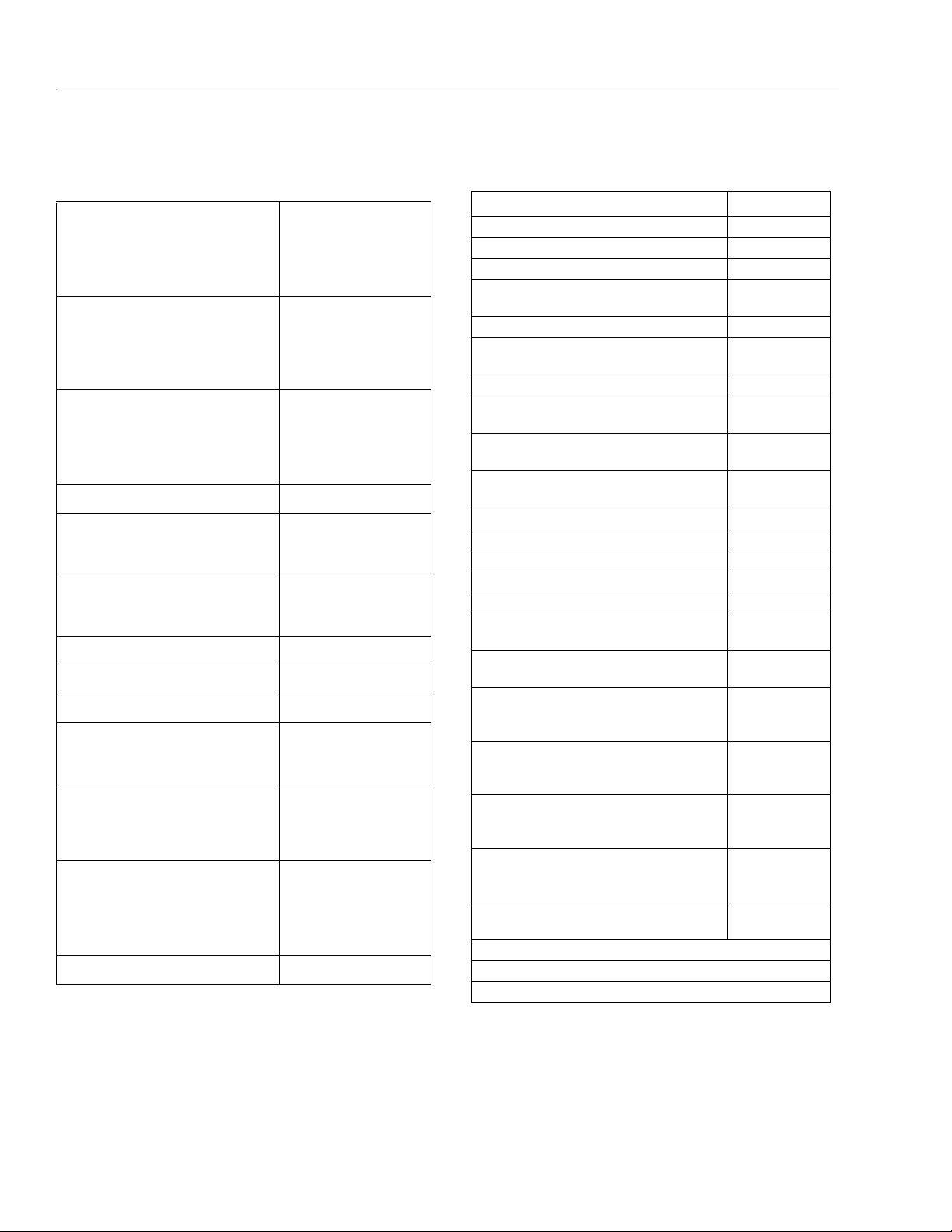
Table 1-3. Battery Charger
Input 110 VAC,60 HZ
Output 48 VDC (25 Amps)
Batteries (8) 6 Volt, 370 Amp Hour (20 hour rate)
Table 1-4. Drive System
Drive Motor 48 VDC, 12.5 H.P. @ 3200 rpm.
continuous, rotation - reversible
Drive Brake- spring-applied, hydraulically released
Drive Brake- spring-applied,
hydraulically released
Table 1-5. Hydraulic Pump/Electric Motor Assembly
Motor 48 VDC, 2.14 H.P. @ 2700 rpm.
Pump 0.098 in.[3]/rev. (1.6 cm[3]/rev.).
Pump Output 2.96 gpm (11.2 lpm) @ 3400 psi (234 Bar).
Table 1-6. Generator
Alternator Output 58 volts @ 45 Amps
RPM’s under max. load 3100
Start Battery 12 volts
Engine Oil 10W30 (Refer to Engine Manual)
Dynamo 12 volt, 15 amp DC
Dynamo Output Fuse 20 amps DC
Control Fuse 15 amps DC
Table 1-7. Tire Data
Size
E/M400A, E/M400AJP
240/55 - 17.5 Pneu. non marking
240/55 - 17.5 Foam Filled
26 x 7 x 20 non marking
240/55 - 17.5 Pneu.
240/55 - Foam Filled
Size
E/M400Anarrow, E/M400AJPnarrow
25 x 7 x 12 - non marking
22 x 6 x 17.5 - non marking
Tire Pressure (pneumatic) 90 psi. (6.2 Bar)
Max. Tire Load
E/M 400Anarrow
E/M400AJP
E/M400AJPnarrow
5160 lbs. (2343 kg)
6300 lbs. (2860 kg)
7200 lbs. (3268 kg)
Ground Bearing Pressure
E/M 400A
E/M 400Anarrow
E/M400AJP
E/M400AJPnarrow
80 psi (5.6kg/cm2)
95 psi (6.6 kg/cm
2
)
80 psi (5.6 kg/cm
2
)
185 psi (13.0 kg/cm
2
)
SECTION 1 - SPECIFICATIONS
1.1 OPERATING SPECIFICATIONS
Table 1-1. Operating Specifications
Maximum Work Load (Capacity)
U nr e st r i ct e d:
Maximum Travel Grade (Gradeablility
Maximum Travel Grade (Side Slope)
Machine Weight (GVW)
E 40 0 An a rr ow
M 40 0 An a rr ow
E 40 0 AJ P
M 40 0 AJ P
E 40 0 AJ Pn a rr ow
M 40 0 AJ Pn a rr ow
System Voltage 48 volts
Battery Life per Charge 7 hours continuous
Battery Recharge Time
C ha r ge r
G en e ra t o r
17 hours from full discharge
500 lb. (230 kg)
30%
13100 lbs. (5942 kg)
13300 lbs. (6033 kg)
13700 lbs. (6214 kg)
13930 lbs. (6318 kg)
14900 lbs. (6759 kg)
15130 lbs. (6862 kg)
6.2 hours
1.2 CAPACITIES
Table 1-2. Capacities
Generator Fuel Tank
4 Gallons (15.1 L)
1.5 HYDRAULIC PUMP/ELECTRIC MOTOR ASSEMBLY
5°
1.6 GENERATOR
1.7 TIRES
Hydraulic Oil Tank
E/M 400A, E/M 400Anarrow
E/M400AJP, E/M400AJPnarrow
Hydraulic System (Including Tank)
Torque Hub, Drive*
*Torque hubs should be one h alf full of lubricant.
1.3 BATTERY CHARGER
1.4 DRIVE SYSTEM
3121827 – JLG Lift – 1-1
4 gallons. (15.14 liters)
5 Gallons (19 L)
9 Gallons (34.1 L)
19 ounces (0.50 L)
SECTION 1 - SPECIFICATIONS
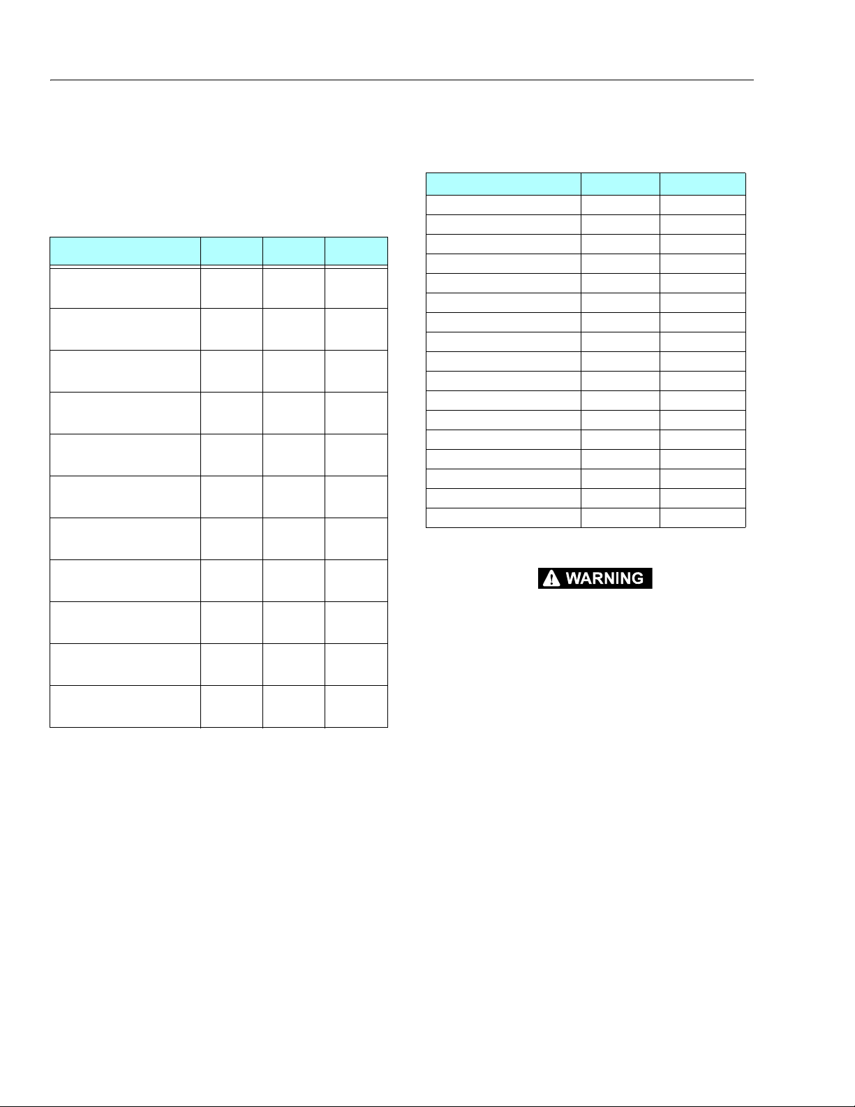
Table 1-9. Function Speeds
Function Seconds
Main Lift Up 30-24
Main Lift Down 29-23
Turntable Swing Right & Left 360° 81-67*
Telescope Out - E400AJP, M400AJP, E400AJPn,
M400AJPn
10-6
Telescope Out - E400An, M400An, E400A, M400A 18-14
Telescope In - E400AJP, M400AJP, E400AJPn,
M400AJPn
15-10
Telescope In - E400An, M400An, E400A, M400A 28-23
Platform Rotate (4 ft.) - Right & Left 180° - E400AJP,
M400AJP, E400AJPn, M400AJPn
20-24**
Platform Rotate (5 ft.) - Right & Left 180° - E400AJP,
M400AJP
16-19**
Platform Rotate - Right & Left 180° - E400An, M400An,
E400A, M400A
17-14**
Jib Up 25-26
Jib Down 24-25
Jib Swing 18-25
Lower Lift Up 33-27
Lower Lift Down 26-22
High Drive - Fwd.& Rev. E400AJP/M400AJP
(200 ft.)
42-44***
3.2 mph. (5.1 kph)
High Drive - Fwd.& Rev. E400AJPn/M400AJPn
(200 ft.)
45-50***
3.0 mph. (4.8 kph)
Drive above Horiz. (ANSI) - Fwd.& Rev. E400A,
E400AJP/M400A, M400AJP
( 50 ft . )
50-53***
0.64 mph (1 kph)
Drive above Horiz.(ANSI)- Fwd.& Rev. E400An/
E400AJPn/M400n, M400AJPn
( 50 f t . )
78-85***
0 .44 mph. (0.7 kph)
Drive above Horiz. (CE) - Fwd.& Rev. E400AJP/
M400AJP
( 50 ft . )
107-112***
0.32 mph (0.5 kph)
Drive above Horiz.(CE) - Fwd.& Rev. E400An/
E400AJPn/M400An/ M400AJPn
( 50 f t . )
78-85***
0 .44 mph. (0.7 kph)
Drive above Horiz.(CE) - Fwd.& Rev. E400A/M400A
( 50 f t . )
67-71***
0 .48 mph. (0.8 kph)
*Swing Left to Swing Right should be within 10% of each other.
**Swing Left to Swing Right should be within 15% of each other.
***Drive Forward to Drive Reverse should be within 10% of each other.
4150273 N
1.8 DIMENSIONAL DATA 1.9 FUNCTION SPEEDS
Table 1-8. Dimensional Data
Machine Height (stowed)
E /M 4 00 A JP
E /M 4 00 A JP na r ro w
E/M 400A
E/M 400Anarrow
Machine Width
E/M 400A
E/M 400Anarrow
E /M 4 00 A JP
E /M 4 00 A JP na r ro w
Machine Length (stowed)
E/M 400A
E/M 400Anarrow
E /M 4 00 A JP
E /M 4 00 A JP na r ro w
Wheel Base 6 ft. 7.0 in. (2.00 m)
Tr ac k W i dt h
E/M 400A, E/M400AJP
E/M 400Anarrow, E/M400AJPnarrow
Ground Clearance
E/M 400A, E/M400AJP
E/M 400Anarrow, E/M400AJPnarrow
Working Height 46 ft. 0 in. (14.02 m)
Platform Height 40 ft. 0 in. (12.19 m)
Up and Over Platform Height 21 ft. 5 in. (6.55 m)
Horizontal Reach @ Maximum Up and Over
E/M 400A, E/M 400Anarrow
E /M 4 00 A JP, E/M400AJPnarrow
Tail Swing (Any Position)
E/M 400A, E/M400AJP, E/M400AJPnarrow
- 0 in.
E/M 400Anarrow - 4 in.
Turning Radius (Inside)
E/M 400A
E/M 400Anarrow
E /M 4 00 A JP
E /M 4 00 A JP na r ro w
Turning Radius (outside) 10 ft.- 4 in. (3.15 m)
E/M 400A, E/M400AJP, E/
6 ft. 7 in. (2.0 m)
6 ft. 5.75 in. (1.31m)
6 ft. 7 in. (2.0 m)
6 ft. 5.75 in. (1.97 m)
5 ft. 9 in. (1.75 m)
4 ft. 11 in. (1.50 m)
5 ft. 9 in. (1.75 m.)
4 ft. 11 in. (1.49 m.)
18 ft. 1 in. (5.50 m)
18 ft. 1 in. (5.50 m)
22.0ft. (6.7 m)
22.0 ft. (6.7 m)
Tr ac k Wi d th
5 ft. 0 in. (1.51 m)
4 ft. 3.75 in.(1.31 m)
8.5 in. (0.22 m)
5 in. (0.13 m)
21 ft. 2 in. (6.41 m)
22 ft.-5 in. (6.83 m)
Tail Swing (Any Position)
M400AJPnarrow - 0 in.
E/M 400Anarrow - 4 in.
2 ft. 0 in. (0.61 m)
2 ft. 10 in. (0.86 m)
2 ft.- 0 in. (0.61 m)
2 ft.-10 in. (0.86 m)
1-2 – JLG Lift – 3121827

SECTION 1 - SPECIFICATIONS
Machine Orientation When Doing Function Tests
1. LIFT:
Boom retracted, telescope retracted. Lift up, record
time. Lift down, record time.
2. SWING:
Boom at full elevation, telescope retracted.
Swing the turntable to the end stop. Swing the
opposite direction. Record time. Swing the other
direction, record time.
3. TELESCOPE:
Boom at full elevation, telescope retracted. Telescope out, record time. Telescope in, record time.
4. DRIVE:
Test should be done on a smooth, level surface.
Start approximately 25 feet from starting point so
that the unit is at a maximum speed when starting
the test. Results should be recorded for a 200 foot
course. Drive forward, record time. Drive reverse,
record time.
5. DRIVE (ABOVE HORIZONTAL):
Test should be done on a smooth, level surface. The
platform speed control knob should be selected out
of creep speed. This verifies that the switches are
working when the boom is above horizontal.
Results should be recorded for a 50 ft. course. Drive
forward, record time. Drive reverse, record time.
6. PLATFORM ROTATE:
Platform level and completely rotated one direction.
Rotate the opposite direction, record time. Rotate
the other direction, record time.
7. JIB:
Platform level and centered with the boom. Start
with the jib down. Jib up, record time. Jib down,
record time.
8. LOWER LIFT:
Upper boom horizontal, telescoped in. Lower lift up,
record time. Lower lift down, record time.
9. JIB SWING:
Platform level and centered with the boom. Start
with the jib horizontal. Begin with jib swing fully to
left. Swing fully to right. Record time. Swing to the
left, record time.
NOTE: Stop watch should be started with the function, not
with the controller or switch.
All speed tests are run from the platform.
The platform speed control knob must be at full
speed. (turned clockwise completely)
The function speeds may vary due to cold thick
hydraulic oil. Tests should be run with oil tempera-
ture above 100
Some flow control functions may not work with the
speed control knob in the creep position.
o
F. ( 3 8o C)
1.10 TORQUE SPECIFICATIONS
Table 1-10. Torque Requirements
Description Tor q ue Va l ue Interval Hours
Wheel Lugs 170 ft. lbs. (230 Nm) 150
Swing Bearing (Loctite)
* Check swing bearing bolts for security after first 50
hours of operation and every 600 hours thereafter.
190 ft. lbs.(260Nm) 50/600*
3121827 – JLG Lift – 1-3
SECTION 1 - SPECIFICATIONS
Table 1-12.Major Component Weights
Component LB. KG.
Platform and Support
215 97.5
Upper Boom Complete
810 367
Mid Boom Complete
550 249
Lower Boom Complete
550 249
Upper Lift Cylinder
89 40
Mid Lift Cylinder
95 43
Lower Lift Cylinder
110 50
Telescope Cylinder
85 38.5
Upper Upright
225 102
Lower Upright
97 44
Turn ta ble
948 430
Battery Box (incl. batteries)
600 272
Chassis (w/ pneu. tires)
4,295 1948
Chassis (w/ foam-filled tires)
4,695 2130
Counterweight
3850 1746
Machine Complete
11,800 5352
Jib
320 145
1.11 CYLINDER SPECIFICATIONS
NOTE: All dimensions are given in inches (in.), with the met-
ric equivalent, millimeters (mm), given in parentheses.
Table 1-11. Cylinder Specifications
Cylinder Bore Stroke Rod Dia.
Upper Lift Cylinder
Mid Lift Cylinder
Lower Lift Cylinder
Telescope Cylinder
Master Cylinder (E/M400A)
Master Cylinder (E/M400AJP)
Slave Cylinder (E/M400A)
3.00
(76.2)
3.00
(76.2)
4.00
(101.6)
2.00
(50.8)
2.00
(50.8)
3.00
(75)
2.00
(50.8)
28.3125
(719.1)
21.25
(539.7)
23.25
(590.5)
92
(2337)
9.375
(238.1)
11.5
(292)
9.375
(238.1)
1.50
(38.1)
1.50
(38.1)
2.25
(57.1)
1.25
(31.8)
1.00
(25.4)
1.25
(32)
1.00
(25.4)
1.12 MAJOR COMPONENT WEIGHTS
Slave Cylinder (E/M400AJP)
3.00
(75)
11.6
(295.5)
1.25
(32)
SELECT LIFTING EQUIPMENT WITH CAPACITY CAPABLE OF
Rotator Cylinder
Steer Cylinder (Double Rod)
Jib Cylinder
1.875
(47.6)
2.50
(63.5)
63.5
(2.5)
15.250
(387.3)
4.06
(103.1)
233.6
(9.2)
1.00
(25.4)
1.75
(44.5)
44.5
(1.75)
SAFELY SUPPORTING WEIGHT.
1-4 – JLG Lift – 3121827
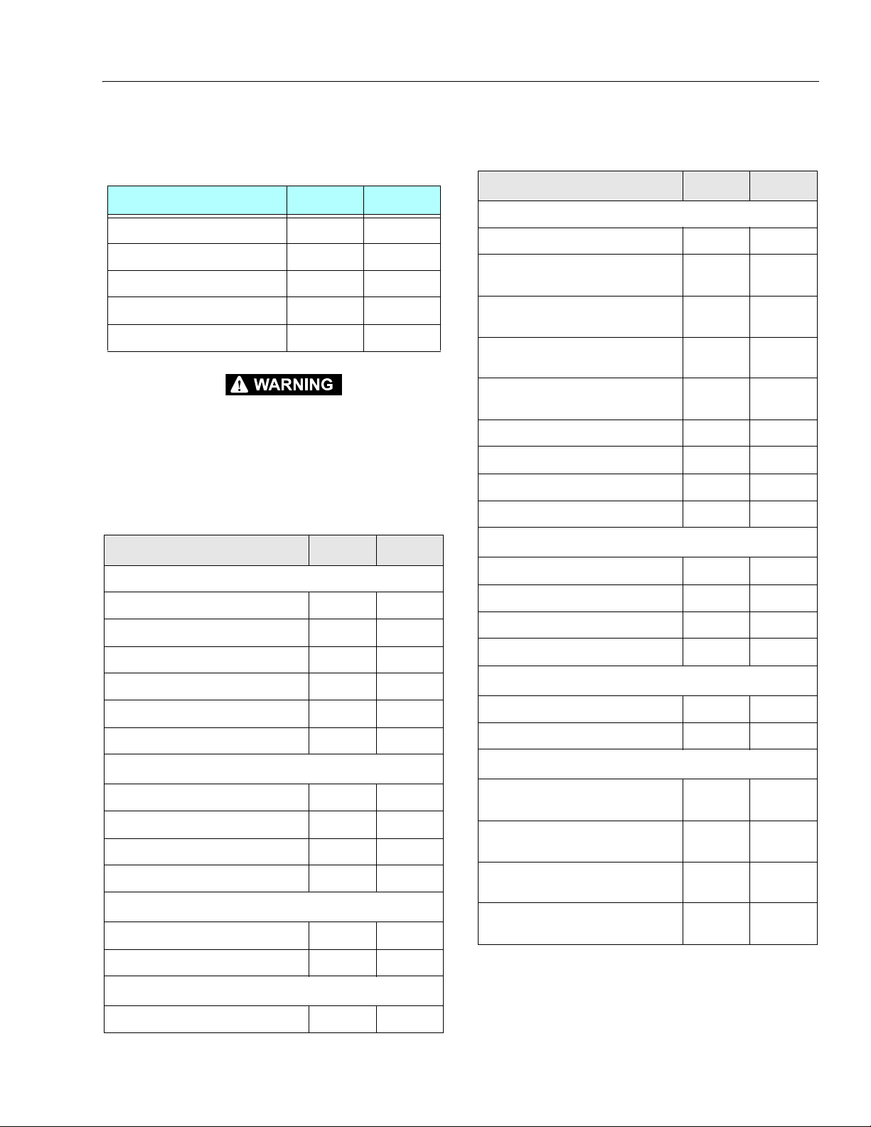
SECTION 1 - SPECIFICATIONS
1.13 CRITICAL STABILITY WEIGHTS
Table 1-13. Critical Stability Weights
Component KG. LB.
Counterweight
Tire & Wheel (foam-filled)
Platform (4ft [1.2 m])
Platform (5 ft. [1.5 m])
Battery (each)
1746 3850
94 207
41 90
45 100
54 120
DO NOT REPLACE ITEMS CRITICAL TO STABILITY WITH ITEMS
OF DIFFERENT WEIGHT OR SPECIFICATION (FOR EXAMPLE: BATTERIES, FILLED TIRES, PLATFORM) DO NOT MODIFY UNIT IN
ANY WAY TO AFFECT STABILITY.
1.14 PRESSURE SETTINGS
Table 1-14. Pressure Settings - Prior to S/N 0300062642
Circuit PSI Bar
Main Control Valve
Lift Down Relief 550 38
Tower Lif t Down Relief
Telescope In Relief (A/AJ) 2150 148
Telescope In Relief (AJP) 3000 207
Platform Level Up Relief 2500 17 2
Platform Level Down Relief 1500 10 3
Brake/Steer Valve
Steer Relief
Steer Relief - AJPn
Main Relief - E400A/M400A
Main Relief - E400AJ/M400AJ
Jib Valve
Jib Relief (Up and Down)
1700 117
2300 159
110 0 76
3200 221
3400 234
1500 103
Table 1-15. Pressure Settings - S/N 0300062642 to
Present
Circuit PSI Bar
Main Control Valve
Lift Down Relief 800 55
Tower Lif t Down Relief (E/M400A)
Prior to S/N 86022
Tower Lif t Down Relief (E/M400A)
S/N 86022 to Present
Tower Lif t Down Relief (E/M400AJP)
Prior to S/N 91053
Tower Lif t Down Relief (E/M400AJP)
S/N 91053 to Present
1700 117
2600 179
1700 117
2600 179
Telescope Relief (A) 3000 207
Telescope Relief (AJ & AJP) 3100 214
Platform Level Up Relief 3000 207
Platform Level Down Relief 1200 83
Brake/Steer Valve
Steer Relief - AJP/A
Steer Relief - An
Steer Relief - AJPn
Main Relief
2300 159
110 0 7 6
1400 96.5
3400 234
Jib Valve
Jib Relief Up
Jib Swing Relief
2200 152
3000 207
Releveling Valve
Releveling Relief (E/M400A)
Prior to S/N 86022
Releveling Relief (E/M400A)
S/N 86022 to Present
Releveling Relief (E/M400AJP)
Prior to S/N 91053
Releveling Relief (E/M400AJP)
S/N 91053 to Present
1200 83
2200 152
1200 83
2200 152
Jib Swing Relief
3000 207
Releveling Valve
Releveling Relief
1200 83
3121827 – JLG Lift – 1-5
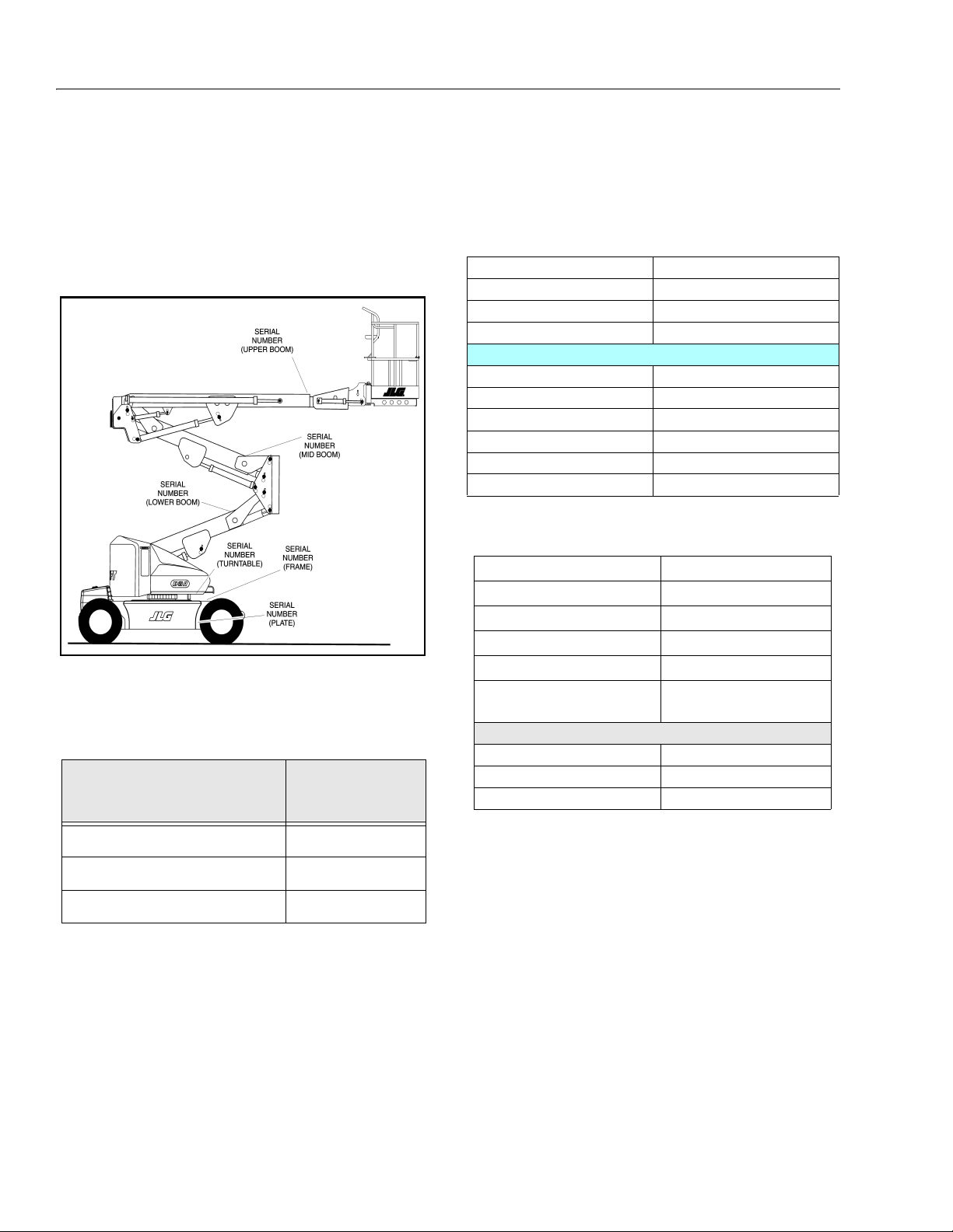
SECTION 1 - SPECIFICATIONS
Figure 1-1. Serial Number Locations
Table 1-18. Mobil EAL H Series Specs
Type Synthetic Biodegradable
ISO Viscosity Grade 32
Specific Gravity .950
Pour Point -59°F (-51°C)
Flash Point 514°F (268°C)
Weight
7.64 lb. per gal.
(0.9 kg per liter)
Viscosity
at 40° C 33.1 cSt
at 100° C 6.36 cSt
Viscosity Index 147
1.15 SERIAL NUMBER LOCATIONS
For machine identification, a serial number plate is affixed
to the left rear of frame, in front of left rear wheel. If the
serial number plate is damaged or missing, the machine
serial number is stamped on the top left side of the frame
and the top left side of the turntable. In addition, the serial
number is stamped on top of the end of the upper boom,
mid boom, and lower boom at the left rear of the booms.
Lubrication Specifications
NOTE: Refer to Lubrication Chart, Figure1-2, for specific
lubrication procedures.
Table 1-17. Mobil DTE 11M Specs
ISO Viscosity Grade #15
Gravity API 31.9
Pour Point, Max -40 °F (-40°C)
Flash Point, Min. 330°F (166°C)
Viscosity
at 40° C 15 cSt
at 100° C 4.1 cSt
at 100° F 80 SUS
at 210° F 43 SUS
cp at -30° F 3.200
Viscosity Index 140
1.16 LUBRICATION
Table 1-16. Hydraulic Oil
Hydraulic System
Operating
Temperature Range
o
to + 180o F(-18o to +83o C)
+0
+0o to + 210o F(-18o to +99o C)
+50o to + 210o F(+10o to +99o C)
NOTE: Hydraulic oils must have anti-wear qualities at least
to API Service Classification GL-3, and sufficient
chemical stability for mobile hydraulic system ser-
1-6 – JLG Lift – 3121827
vice.
Aside from JLG recommendations, it is not advisable
to mix oils of different brands or types, as they may
not contain the same required additives or be of
comparable viscosities. If use of hydraulic oil other
than Mobil DTE 11M is desired, contact JLG Industries for proper recommendations.
S.A.E. Viscosity
Grade
10W
10W-20, 10W30
20W-20
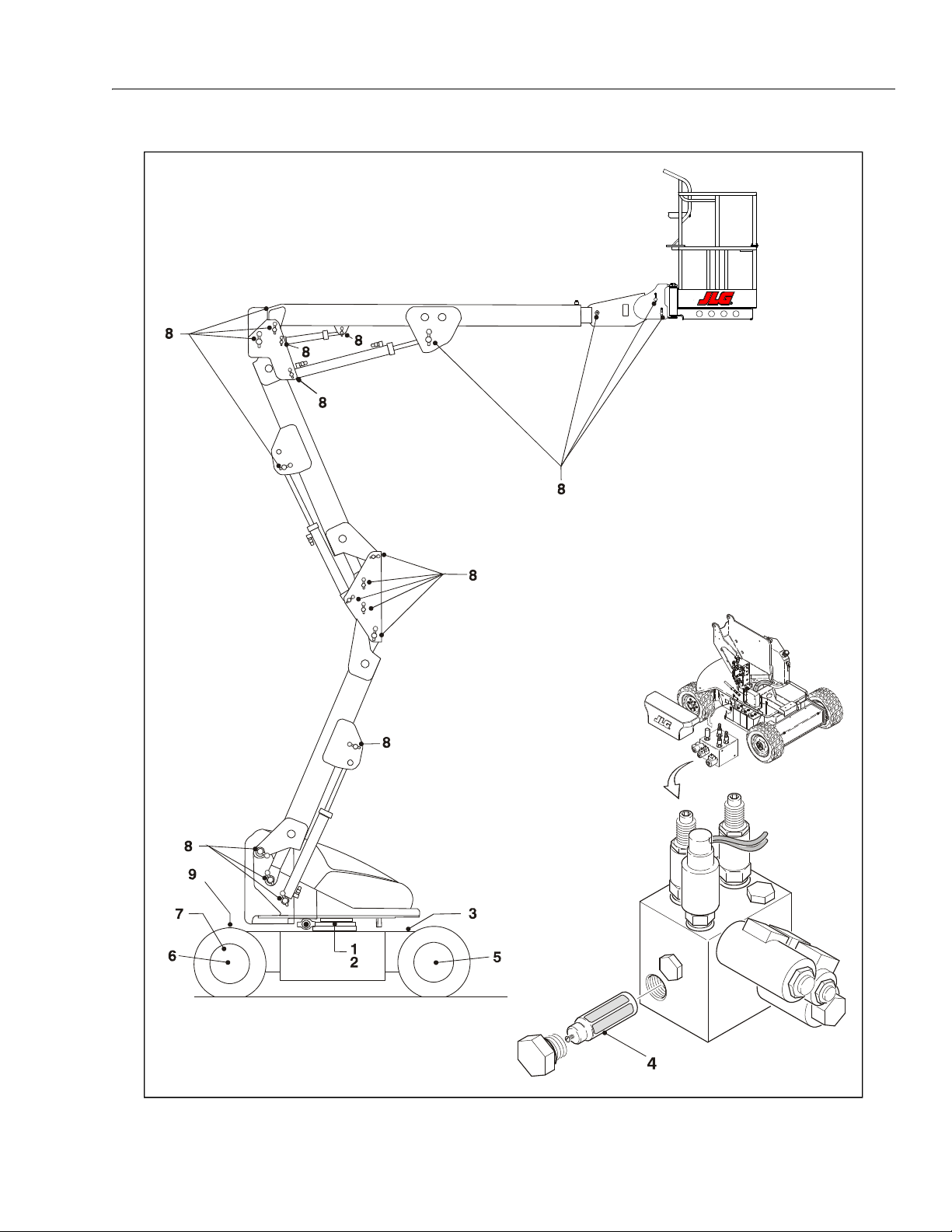
SECTION 1 - SPECIFICATIONS
Figure 1-2. Operator Maintenance & Lubrication Diagram
3121827 – JLG Lift – 1-7
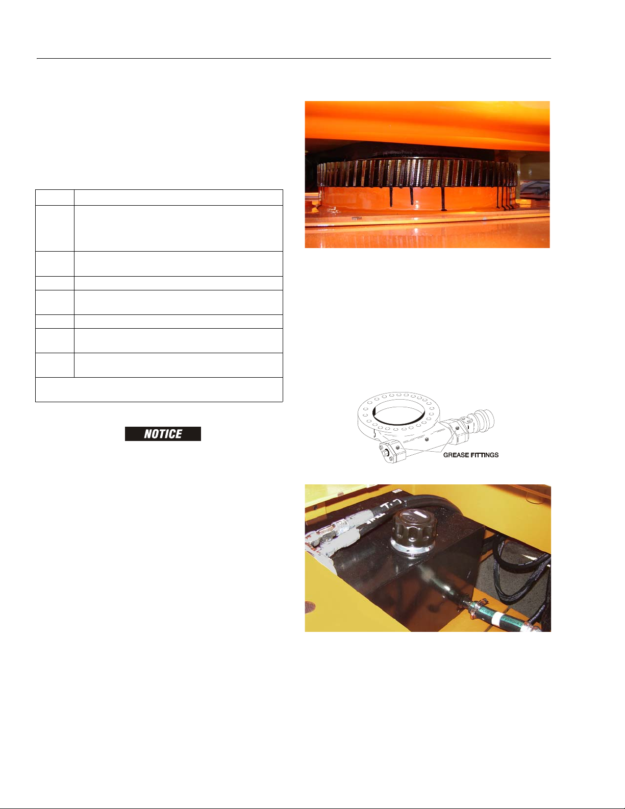
SECTION 1 - SPECIFICATIONS
Table 1-19. Lubrication Specifications.
KEY SPECIFICATIONS
MPG Multipurpose Grease having a minimum dripping poin t of 350
degrees F. Excellent water resistance and adhesive qualities;
and being of extreme pressure type (Timken OK 40 poun ds minimum).
EPGL Extreme Pressure Gear Lube (oil) meeting API Service Classifi-
cation GL-5 or Mil-Spec Mil-L-2105.
HO Hydraulic Oil. Mobil DTE-11M
OG* Open Gear Lube - Tribol Molub-Alloy 936 Open Gear Com-
pound. (JLG Part No. 3020027)
BG* Bearing Grease (JLG Part No. 3020029) Mobilith SHA 460.
LL Synthetic Lithium L ubricant, Gredag 741 Grease. (JLG Part No.
3020022)
EO Engine (crankcase) Oil. Gas - API SF/SG class, MIL-L-2104.
D ie se l - AP I C C /C D c la ss , M I L-L- 21 04 B/ MI L-L- 2 10 4C .
*MPG may be substituted for these lubricants, if necessary, but service
intervals will be reduced.
1.17 OPERATOR MAINTENANCE & LUBRICATION
NOTE: The following numbers correspond to those in Fig-
ure 1-2., Operator Maintenance & Lubrication Diagram.
2. Swing Bearing/Worm Gear Teeth
Lube Point(s) - 2 Grease Fittings
Capacity - Spray On
Lube - Mobiltac 375NC
Interval - A/R
Comments - If necessary install grease fittings into
worm gear housing and grease bearings.
DO NOT OVERGREASE BEARINGS. OVERGREASING BEARINGS
WILL RESULT IN BLOWING OUTER SEAL IN HOUSING.
LUBRICATION INTERVALS ARE BASED ON MACHINE OPERATION
UNDER NORMAL CONDITIONS. FOR MACHINES USED IN MULTISHIFT OPERATIONS AND/OR EXPOSED TO HOSTILE ENVIRONMENTS OR CONDITIONS, LUBRICATION FREQUENCIES MUST BE
INCREASED ACCORDINGLY.
1. Swing Bearing
Lube Point(s) - 2 Grease Fittings
Capacity - A/R
Lube - MPG
Interval - Every 3 months or 150 hrs of operation
1-8 – JLG Lift – 3121827
Comments - Remote Access
3. Hydraulic Tank
Lube Point(s) - Fill Cap
Capacity - 4 Gal. (15.1 L)
Lube - HO
Interval - Check Level daily; Change every 2 years or
1200 hours of operation.
Comments - On new machines, those recently over-
hauled, or after changing hydraulic oil, operate
all systems a minimum of two complete cycles
and recheck oil level in reservoir.
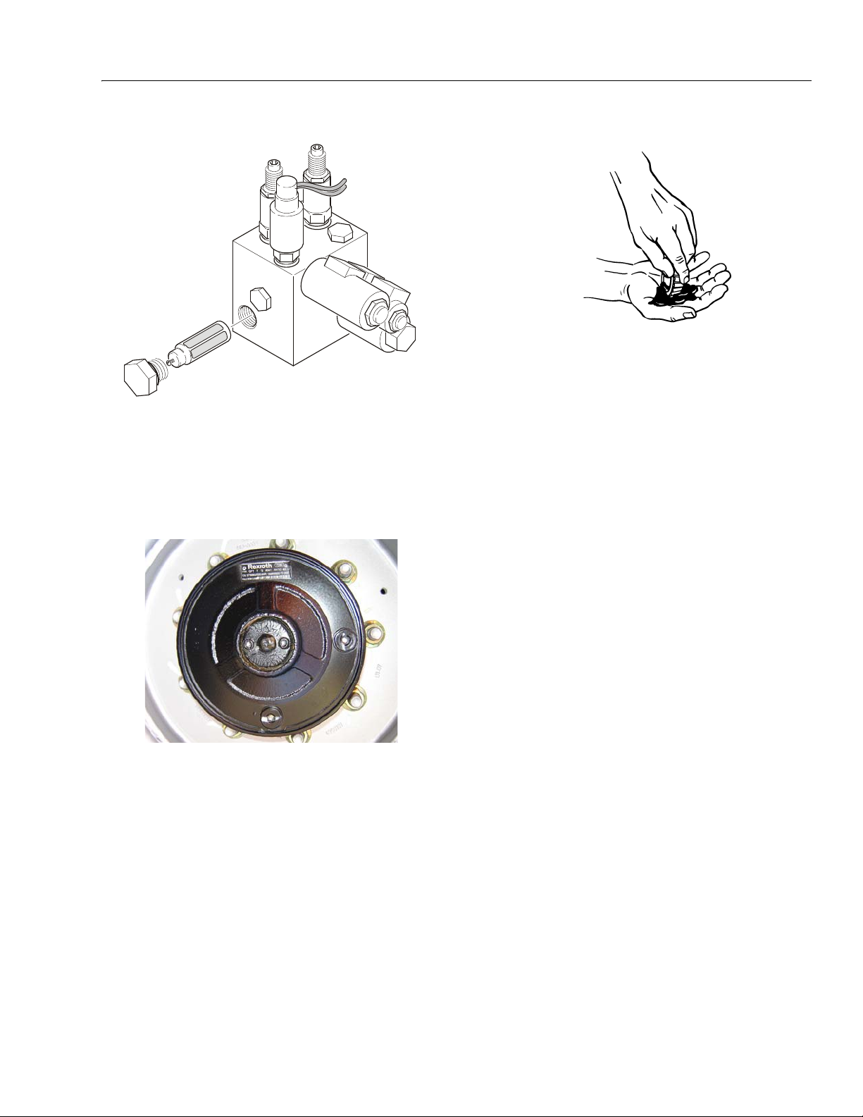
SECTION 1 - SPECIFICATIONS
4. Hydraulic Return Filter
Interval - Change after first 50 hrs. and every 6
months or 300 hrs. thereafter.
Comments - Under certain conditions, it may be
necessary to replace the hydraulic filter on a
more frequent basis. A common symptom of a
dirty filter is sluggishness experienced in hydraulic functions.
5. Wheel Drive Hub
6. Wheel Bearings
Lube Point(s) - Repack
Capacity - A/R
Lube - MPG
Interval - Every 2 years or 1200 hours of operation
7. Spindles/Bushing
Capacity - A/R
Lube - Lithium Lubricant
Interval - Every 2 years or 1200 hours of operation
Comments - At Spindle/Bushing Replacement; Coat
I.D. of bushings prior to installing king pins.
8. Boom Pivot Pins/Bushing
Capacity - A/R
Lube - Lithium Lubricant
Interval - Every 2 years or 1200 hours of operation
Comments - At boom pivot pins/bushing replace-
ment; Coat I.D. of bushings prior to installing
pivot pins.
Lube Point(s) - Level/Fill Plug
Capacity - 17 oz. (1/2 Full)
Lube - EPGL
Interval - Check level every 3 months or 150 hrs of
operation; change every 2 years or 1200 hours
of operation
3121827 – JLG Lift – 1-9
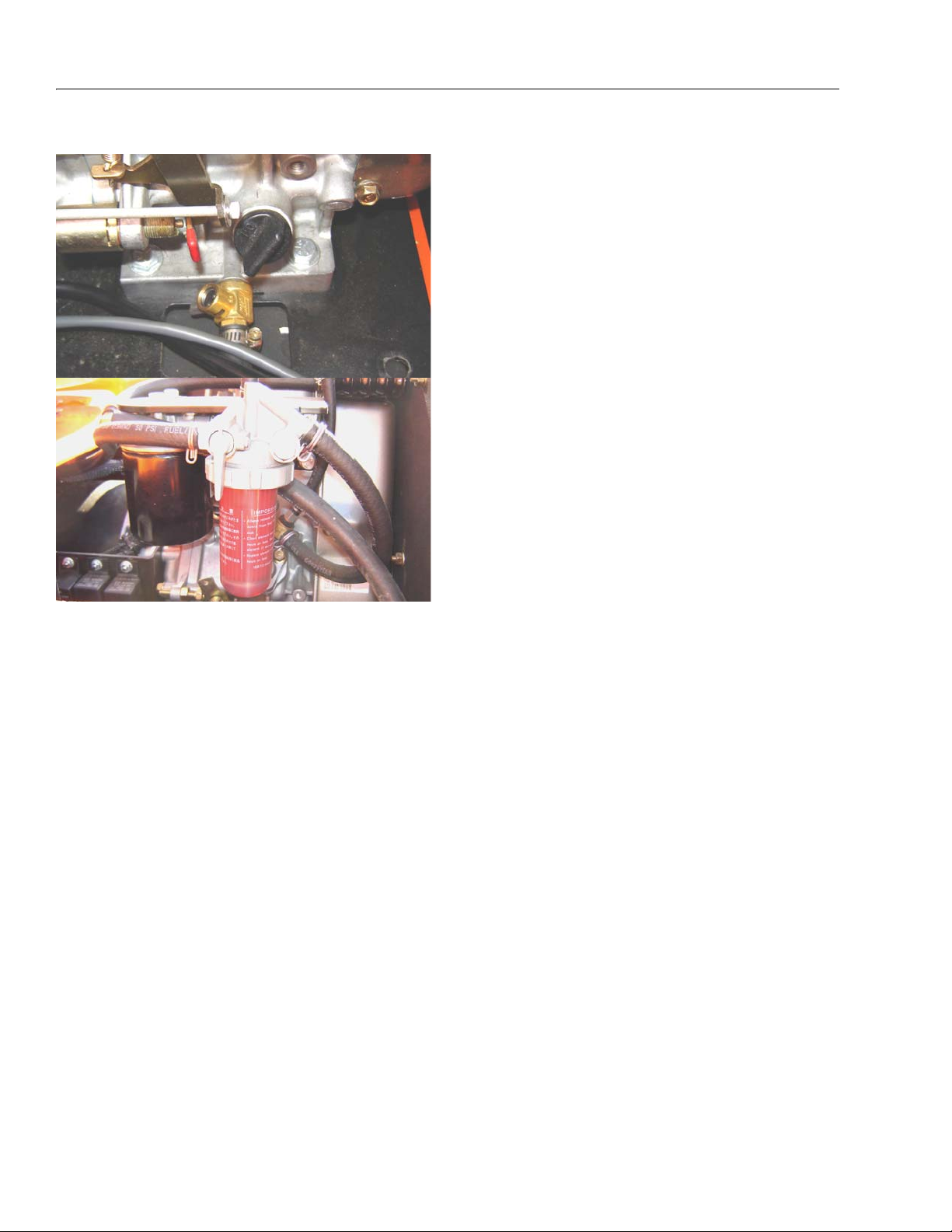
SECTION 1 - SPECIFICATIONS
9. Engine
Lube Point(s) - Fill Cap
Capacity - Refer to Engine Manual
Lube - EO
Interval - 3 Months or 150 hours of operation
Comments - Check level daily/Change in accor-
dance with engine manual.
1-10 – JLG Lift – 3121827
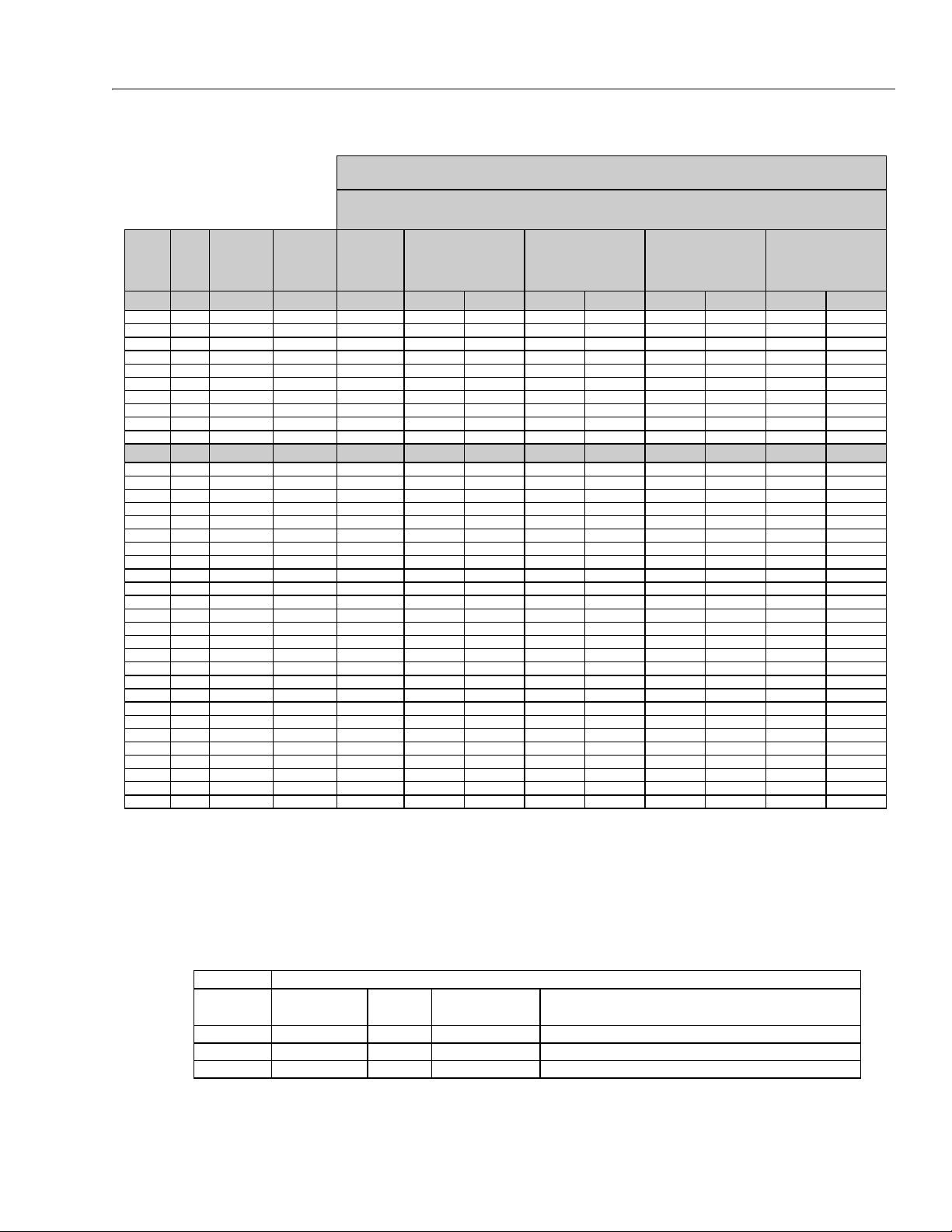
SECTION 1 - SPECIFICATIONS
REFERENCE JLG ANEROBIC THREAD LOCKING COMPOUND
JLG P/N Loctite® P/N ND Industries P/N
Description
0100011
242
TM
Vibra-TITE
TM
121
Medium Strength (Blue)
0100019
271
TM
Vibra-TITE
TM
140
High Strength (Red)
0100071
262
TM
Vibra-TITE
TM
131
Medium - High Strength (Red)
Size TPI Bolt Dia
Tensile
Stress Area
Clamp Load
In Sq In LB IN-LB [N.m] IN-LB [N.m] IN-LB [N.m] IN-LB [N.m]
4 40 0.1120 0.00604 380 8 0.9 6 0.7
48 0.1120 0.00661 420 9 1.0 7 0.8
6 32 0.1380 0.00909 580 16 1.8 12 1.4
40 0.1380 0.01015 610 18 2.0 13 1.5
8 32 0.1640 0.01400 900 30 3.4 22 2.5
36 0.1640 0.01474 940 31 3.5 23 2.6
10 24 0.1900 0.01750 1120 43 4.8 32 3.5
32 0.1900 0.02000 1285 49 5.5 36 4
1/4 20 0.2500 0.0318 2020 96 10.8 75 9 105 12
28 0.2500 0.0364 2320 120 13.5 86 10 135 15
In Sq In LB FT-LB [N.m] FT-LB [N.m] FT-LB [N.m] FT-LB [N.m]
5/16 18 0.3125 0.0524 3340 17 23 13 18 19 26 16 22
24 0.3125 0.0580 3700 19 26 14 19 21 29 17 23
3/8 16 0.3750 0.0775 4940 30 41 23 31 35 48 28 38
24 0.3750 0.0878 5600 35 47 25 34 40 54 32 43
7/16 14 0.4375 0.1063 6800 50 68 35 47 55 75 45 61
20 0.4375 0.1187 7550 55 75 40 54 60 82 50 68
1/2 13 0.5000 0.1419 9050 75 102 55 75 85 116 68 92
20 0.5000 0.1599 10700 90 122 65 88 100 136 80 108
9/16 12 0.5625 0.1820 11600 110 149 80 108 120 163 98 133
18 0.5625 0.2030 12950 120 163 90 122 135 184 109 148
5/8 11 0.6250 0.2260 14400 150 203 110 149 165 224 135 183
18 0.6250 0.2560 16300 170 230 130 176 190 258 153 207
3/4 10 0.7500 0.3340 21300 260 353 200 271 285 388 240 325
16 0.7500 0.3730 23800 300 407 220 298 330 449 268 363
7/8 9 0.8750 0 .4620 29400 430 583 320 434 475 646 386 523
14 0.8750 0.5090 32400 470 637 350 475 520 707 425 576
1 8 1.0000 0.6060 38600 640 868 480 651 675 918 579 785
12 1.0000 0.6630 42200 700 949 530 719 735 1000 633 858
1 1/8 7 1.1250 0.7630 42300 800 1085 600 813 840 1142 714 968
12 1.1250 0.8560 47500 880 1193 660 895 925 1258 802 1087
1 1/4 7 1.2500 0.9690 53800 1120 1518 840 1139 1175 1598 1009 1368
12 1.2500 1.0730 59600 1240 1681 920 1247 1300 1768 1118 1516
1 3/8 6 1.3750 1.1550 64100 1460 1979 1100 1491 1525 2074 1322 1792
12 1.3750 1.3150 73000 1680 2278 1260 1708 1750 2380 1506 2042
1 1/2 6 1.5000 1.4050 78000 1940 2630 1460 1979 2025 2754 1755 2379
12 1.5000 1.5800 87700 2200 2983 1640 2224 2300 3128 1974 2676
NO. 5000059 REV. J
Values for Zinc Yellow Chromate Fasteners (Ref 4150707)
SAE GRADE 5 BOLTS & GRADE 2 NUTS
Torque
(Dry)
Torque
(Loctite® 262
TM
or Vibra-
TITE
TM
131)
Torque
Lubricated
Torque
(Loctite® 242
TM
or 271
TM
OR Vibra-TIT E
TM
111 or
140)
3. * ASSEMBLY USES HARDENED WASHER
NOTES: 1. THESE TORQUE VALUES DO NOT APPLY TO CADMIUM PLATED FASTENERS
2. ALL TORQUE VALUES ARE STATIC TORQUE MEASURED PER STANDARD AUDIT METHODS TOLERANCE = ±10%
Figure 1-3. Torque Chart (SAE Fasteners - Sheet 1 of 7)
3121827 – JLG Lift – 1-11
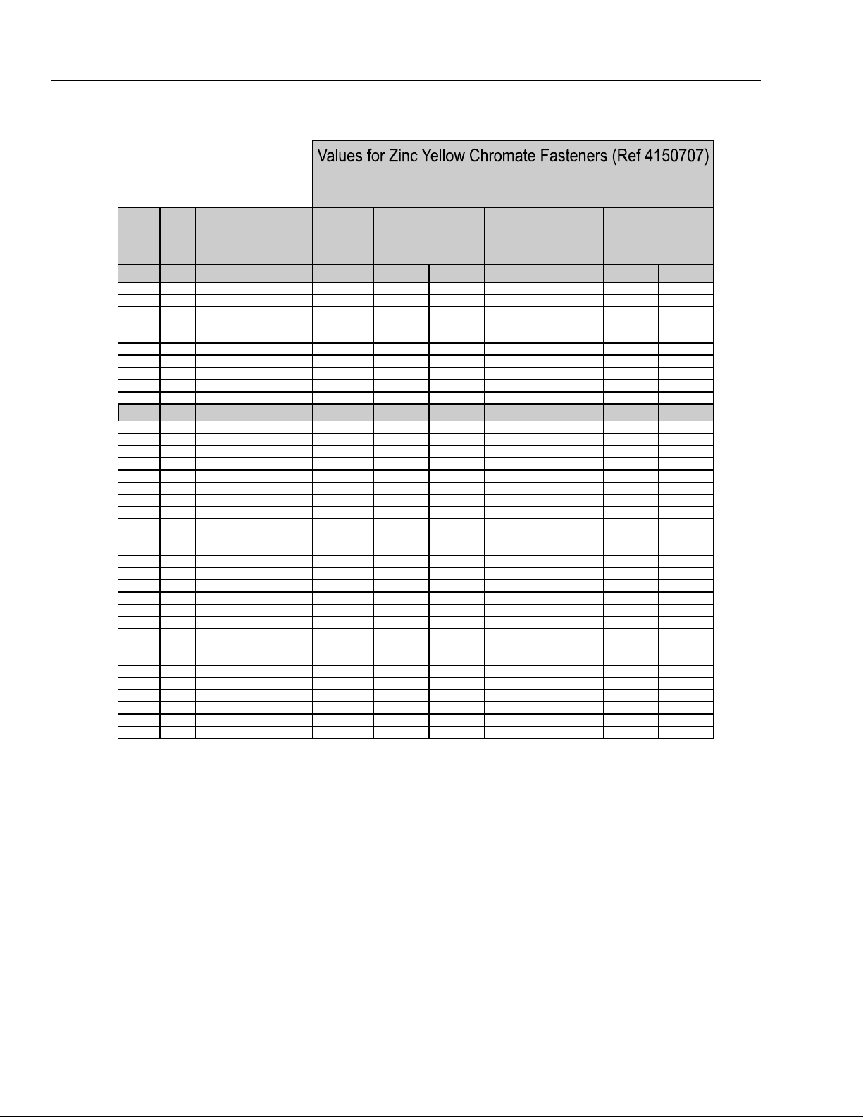
SECTION 1 - SPECIFICATIONS
Size TPI Bolt Dia
Tensile
Stress Area
Clamp Load
In Sq In
4 40 0.1120 0.00604
48 0.1120 0.00661
6 32 0.1380 0.00909
40 0.1380 0.01015
8 32 0.1640 0.01400
36 0.1640 0.01474
10 24 0.1900 0.01750
32 0.1900 0.02000
1/4 20 0.2500 0.0318
28 0.2500 0.0364
In Sq In
5/16 18 0.3125 0.0524
24 0.3125 0.0580
3/8 16 0.3750 0.0775
24 0.3750 0.0878
7/16 14 0.4375 0.1063
20 0.4375 0.1187
1/2 13 0.5000 0.1419
20 0.5000 0.1599
9/16 12 0.5625 0.1820
18 0.5625 0.2030
5/8 11 0.6250 0.2260
18 0.6250 0.2560
3/4 10 0.7500 0.3340
16 0.7500 0.3730
7/8 9 0.8750 0.4620
14 0.8750 0.5090
1 8 1.0000 0.6060
12 1.0000 0.6630
1 1/8 7 1.1250 0.7630
12 1.1250 0.8560
1 1/4 7 1.2500 0.9690
12 1.2500 1.0730
1 3/8 6 1.3750 1.1550
12 1.3750 1.3150
1 1/2 6 1.5000 1.4050
12 1.5000 1.5800
NO. 5000059 REV. J
3. * ASSEMBLY USES HARDENED WASHER
NOTES: 1. THESE TORQUE VALUES DO NOT APPLY TO CADMIUM PLATED FASTENERS
2. ALL TORQUE VALUES ARE STATIC TORQUE MEASURED PER STANDARD AUDIT METHODS TOLERANCE = ±10%
LB IN-LB [N.m] IN-LB [N.m] IN-LB [N.m]
1320 43 5
1580 60 7
1800 68 8
2860 143 16 129 15
3280 164 19 148 17
LB FT-LB [N.m] FT-LB [N.m] FT-LB [N.m
4720 25 35 20 25 20 25
5220 25 35 25 35 20 25
7000456040 553550
7900 50 70 45 60 35 50
9550 70 95 65 90 50 70
10700 80 110 70 95 60 80
12750 105 145 95 130 80 110
14400 120 165 110 150 90 120
16400 155 210 140 190 115 155
18250 170 230 155 210 130 175
20350 210 285 190 260 160 220
23000 240 325 215 290 180 245
30100 375 510 340 460 280 380
33600 420 570 380 515 315 430
41600 605 825 545 740 455 620
45800 670 910 600 815 500 680
51500 860 1170 770 1045 645 875
59700 995 1355 895 1215 745 1015
68700 1290 1755 1160 1580 965 1310
77000 1445 1965 1300 1770 1085 1475
87200 1815 2470 1635 2225 1365 1855
96600 2015 2740 1810 2460 1510 2055
104000 2385 3245 2145 2915 1785 2430
118100 2705 3680 2435 3310 2030 2760
126500 3165 4305 2845 3870 2370 3225
142200 3555 4835 3200 4350 2665 3625
Torque
(Loctite® 242
TM
or 271
TM
OR Vibra-TITE
TM
111 or
140) K=.18
Torque
(Loctite® 262
TM
or Vibra-
TITE
TM
131)
K=0.15
SAE GRADE 8 (HEX HD) BOLTS & GRADE 8 NUTS*
Torque
(Dry or Loctite® 263)
K= 0.20
1-12 – JLG Lift – 3121827
Figure 1-4. Torque Chart (SAE Fasteners - Sheet 2 of 7)
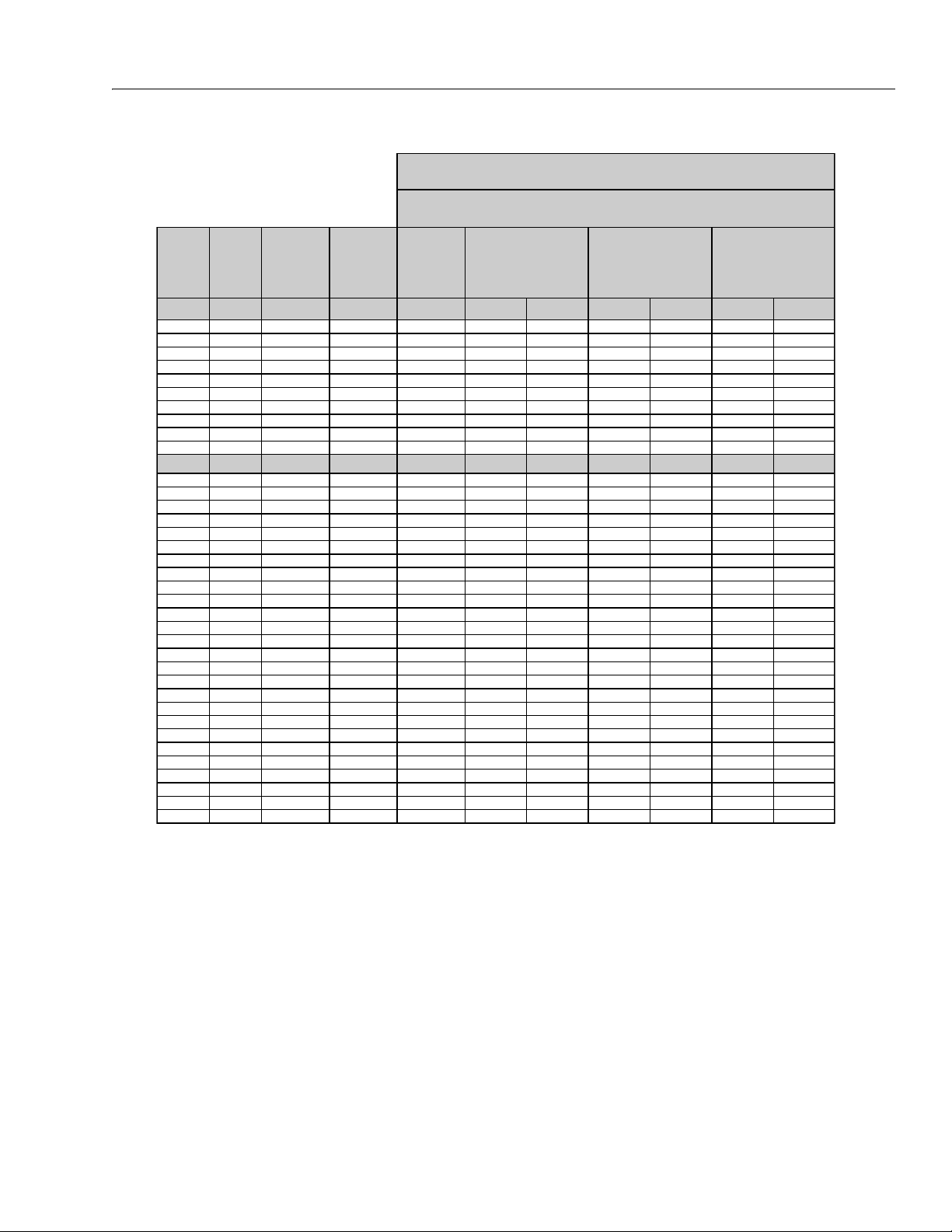
Size TPI Bolt Dia
Tensile
Stress Area
Clamp Load
See Note 4
In Sq In LB IN-LB [N.m] IN-LB [N.m] IN-LB [N.m]
4 40 0.1120 0.00604
48 0.1120 0.00661
6 32 0.1380 0.00909
40 0.1380 0.01015
8 32 0.1640 0.01400
36 0.1640 0.01474
10 24 0.1900 0.01750
32 0.1900 0.02000
1/4 20 0.2500 0.0318 2860 122 14 114 13
28 0.2500 0.0364 3280 139 16 131 15
In Sq In LB FT-LB [N.m] FT-LB [N.m] FT-LB [N.m]
5/16 18 0.3125 0.0524 4720 20 25 20 25 20 25
24 0.3125 0.0580 5220 25 35 20 25 20 25
3/8 16 0.3750 0.0775 7000 35 50 35 50 35 50
24 0.3750 0.0878 7900 40 55 40 55 35 50
7/16 14 0.4375 0.1063 9550 60 80 55 75 50 70
20 0.4375 0.1187 10700 65 90 60 80 60 80
1/2 13 0.5000 0.1419 12750 90 120 85 115 80 110
20 0.5000 0.1599 14400 100 135 95 130 90 120
9/16 12 0.5625 0.1820 16400 130 175 125 170 115 155
18 0.5625 0.2030 18250 145 195 135 185 130 175
5/8 11 0.6250 0.2260 20350 180 245 170 230 160 220
18 0.6250 0.2560 23000 205 280 190 260 180 245
3/4 10 0.7500 0.3340 30100 320 435 300 410 280 380
16 0.7500 0.3730 33600 355 485 335 455 315 430
7/8 9 0.8750 0.4620 41600 515 700 485 660 455 620
14 0.8750 0.5090 45800 570 775 535 730 500 680
1 8 1.0000 0.6060 51500 730 995 685 930 645 875
12 1.0000 0.6630 59700 845 1150 795 1080 745 1015
1 1/8 7 1.1250 0.7630 68700 1095 1490 1030 1400 965 1310
12 1.1250 0.8560 77000 1225 1665 1155 1570 1085 1475
1 1/4 7 1.2500 0.9690 87200 1545 2100 1455 1980 1365 1855
12 1.2500 1.0730 96600 1710 2325 1610 2190 1510 2055
1 3/8 6 1.3750 1.1550 104000 2025 2755 1905 2590 1785 2430
12 1.3750 1.3150 118100 2300 3130 2165 2945 2030 2760
1 1/2 6 1.5000 1.4050 126500 2690 3660 2530 3440 2370 3225
12 1.5000 1.5800 142200 3020 4105 2845 3870 2665 3625
NO. 5000059 REV. J
4. CLAMP LOAD LISTED FOR SHCS IS SAME AS GRADE 8 OR CLASS 10.9 AND DOES NOT REPRESENT FULL STRENGTH
CAPABILITY OF SHCS. IF HIGHER LOAD IS REQUIRED, ADDITIONAL TESTING IS REQUIRED.
SOCKET HEAD CAP SCREWS
Magni Coating (Ref 4150701)*
Torque
(Dry) K = .17
Torque
(Loctite® 242
TM
or 271
TM
OR Vibra-TITE
TM
111 or
140 OR Precoat 85®
K=0.16
Torque
(Loctite® 262
TM
or Vibra-
TITE
TM
131)
K=0.15
2. ALL TORQUE VALUES ARE STATIC TORQUE MEASURED PER STANDARD AUDIT METHODS TOLERANCE = ±10%
NOTES: 1. THESE TORQUE VALUES DO NOT APPLY TO CADMIUM PLATED FASTENERS
*3. ASSEMBLY USES HARDENED WASHER OR FASTENER IS PLACED AGAINST PLATED STEEL OR RAW ALUMINUM
SECTION 1 - SPECIFICATIONS
3121827 – JLG Lift – 1-13
Figure 1-5. Torque Chart (SAE Fasteners - Sheet 3 of 7)
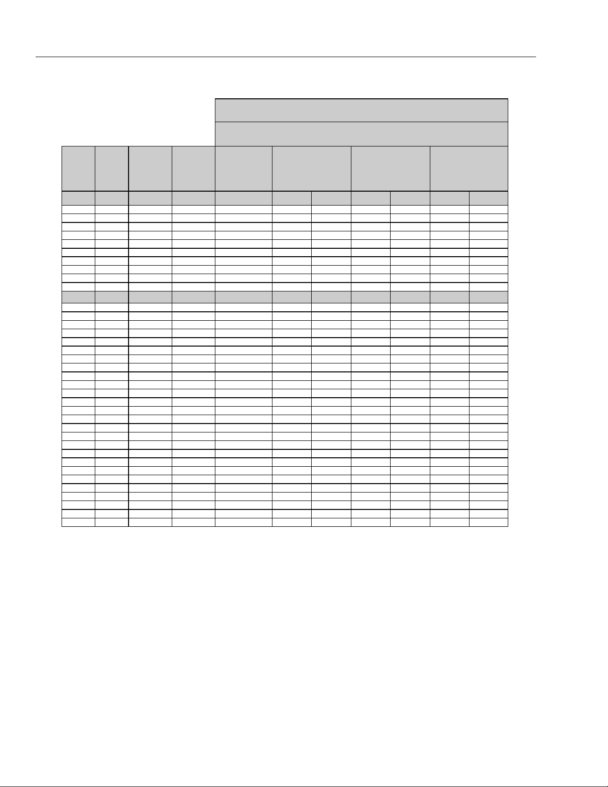
SECTION 1 - SPECIFICATIONS
Size TPI Bolt Dia
Tensile
Stress Area
Clamp Load
See Note 4
In Sq In LB IN-LB [N.m] IN-LB [N.m] IN-LB [N.m]
4 40 0.1120 0.00604
48 0.1120 0.00661
6 32 0.1380 0.00909
40 0.1380 0.01015
8 32 0.1640 0.01400
36 0.1640 0.01474
10 24 0.1900 0.01750
32 0.1900 0.02000
1/4 20 0.2500 0.0318 2860 143 16 129 15
28 0.2500 0.0364 3280 164 19 148 17
In Sq In LB FT-LB [N.m] FT-LB [N.m] FT-LB [N.m]
5/16 18 0.3125 0.0524 4720 25 35 20 25 20 25
24 0.3125 0.0580 5220 25 35 25 35 20 25
3/8 16 0.3750 0.0775 7000 45 60 40 55 35 50
24 0.3750 0.0878 7900 50 70 45 60 35 50
7/16 14 0.4375 0.1063 9550 70 95 65 90 50 70
20 0.4375 0.1187 10700 80 110 70 95 60 80
1/2 13 0.5000 0.1419 12750 105 145 95 130 80 110
20 0.5000 0.1599 14400 120 165 110 150 90 120
9/16 12 0.5625 0.1820 16400 155 210 140 190 115 155
18 0.5625 0.2030 18250 170 230 155 210 130 175
5/8 11 0.6250 0.2260 20350 210 285 190 260 160 220
18 0.6250 0.2560 23000 240 325 215 290 180 245
3/4 10 0.7500 0.3340 30100 375 510 340 460 280 380
16 0.7500 0.3730 33600 420 570 380 515 315 430
7/8 9 0.8750 0.4620 41600 605 825 545 740 455 620
14 0.8750 0.5090 45800 670 910 600 815 500 680
1 8 1.0000 0.6060 51500 860 1170 775 1055 645 875
12 1.0000 0.6630 59700 995 1355 895 1215 745 1015
1 1/8 7 1.1250 0.7630 68700 1290 1755 1160 1580 965 1310
12 1.1250 0.8560 77000 1445 1965 1300 1770 1085 1475
1 1/4 7 1.2500 0.9690 87200 1815 2470 1635 2225 1365 1855
12 1.2500 1.0730 96600 2015 2740 1810 2460 1510 2055
1 3/8 6 1.3750 1.1550 104000 2385 3245 2145 2915 1785 2430
12 1.3750 1.3150 118100 2705 3680 2435 3310 2030 2760
1 1/2 6 1.5000 1.4050 126500 3165 4305 2845 3870 2370 3225
12 1.5000 1.5800 142200 3555 4835 3200 4350 2665 3625
NO. 5000059 REV. J
4. CLAMP LOAD LISTED FOR SHCS IS SAME AS GRADE 8 OR CLASS 10.9 AND DOES NOT REPRESENT FULL STRENGTH
CAPABILITY OF SHCS. IF HIGHER LOAD IS REQUIRED, ADDITIONAL TESTING IS REQUIRED.
SOCKET HEAD CAP SCREWS
Torque
(Dry)
K = .20
Torque
(Loctite® 242TM or 271
TM
OR Vibra-TITE
TM
111 or
140 OR Precoat 85®
K=0.18
Zinc Yellow Chromate Fasteners (Ref 4150707)*
2. ALL TORQUE VALUES ARE STATIC TORQUE MEASURED PER STANDARD AUDIT METHODS TOLERANCE = ±10%
NOTES: 1. THESE TORQUE VALUES DO NOT APPLY TO CADMIUM PLATED FASTENERS
*3. ASSEMBLY USES HARDENED WASHER OR FASTENER IS PLACED AGAINST PLATED STEEL OR RAW ALUMINUM
Torque
(Loctite® 262
TM
or Vibra-
TITE
TM
131)
K=0.15
1-14 – JLG Lift – 3121827
Figure 1-6. Torque Chart (SAE Fasteners - Sheet 4 of 7)
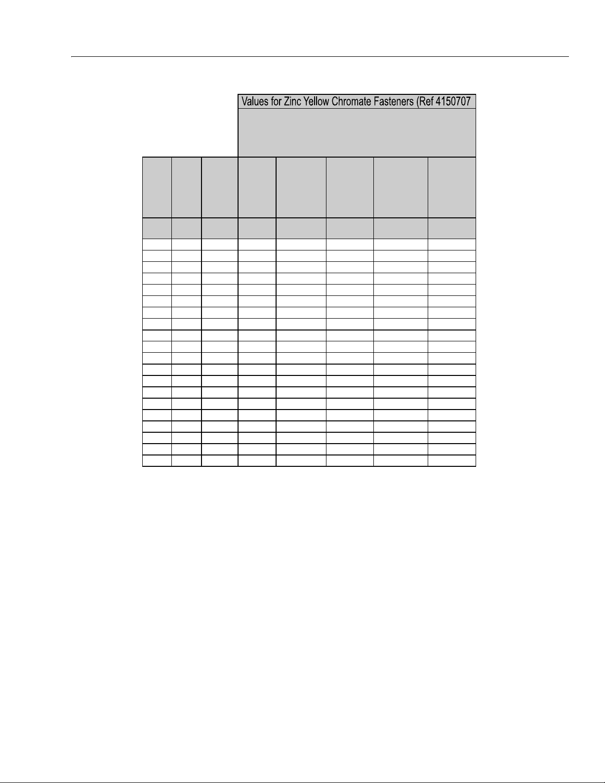
SECTION 1 - SPECIFICATIONS
Size PITCH
Tensile
Stress
Area
Clamp
Load
Torque
(Dry or Loctite®
263
TM
)
Torque
(Lub)
Torque
(Loctite® 262
TM
OR Vibra-
TITE
TM
131)
Torque
(Loctite®
242
TM
or 271
TM
OR Vibra-
TITE
TM
111 or
140)
Sq mm K N [N.m] [N.m] [N.m] [N. m]
3 0.5 5.03 2.19 1.3 1.0 1.2 1.4
3.5 0.6 6.78 2.95 2.1 1.6 1.9 2.3
4 0.7 8.78 3.82 3.1 2.3 2.8 3.4
5 0.8 14.20 6.18 6.2 4.6 5.6 6.8
6 1 20.10 8.74 11 7.9 9.4 12
7 1 28.90 12.6 18 13 16 19
8 1.25 36.60 15.9 26 19 23 28
10 1.5 58.00 25.2 50 38 45 55
12 1.75 84.30 36.7 88 66 79 97
14 2 115 50.0 140 105 126 154
16 2 157 68.3
219 164 197 241
18 2.5 192 83.5 301 226 271 331
20 2.5 245 106.5 426 320 383 469
22 2.5 303 132.0 581 436 523 639
24 3 353 153.5 737 553 663 811
27 3 459 199.5 1080 810 970 1130
30 3.5 561 244.0 1460 1100 1320 1530
33 3.5 694 302.0 1990 1490 1790 2090
36 4 817 355.5 2560 1920 2300 2690
42 4.5 1120 487.0 4090 3070 3680 4290
4. CLAMP LOAD LISTED FOR SHCS IS SAME AS GRADE 8 OR CLASS 10.9 AND DOES NOT
REPRESENT FULL STRENGTH CAPABILITY OF SHCS. IF HIGHER LOAD IS REQUIRED,
ADDITIONAL TESTING IS REQUIRED.
*3. ASSEMBLY USES HARDENED WASHER OR FASTENER IS PLACED AGAINST PLATED
STEEL OR RAW ALUMINUM
CLASS 8.8 METRIC BOLTS
CLASS 8 METRIC NUTS
NOTES: 1. THESE TORQUE VALUES DO NOT APPLY TO CADMIUM PLATED FASTENERS
2. ALL TORQUE VALUES ARE STATIC TORQUE MEASURED PER STANDARD AUDIT
METHODS TOLERANCE = ±10%
NO. 5000059 REV. J
Figure 1-7. Torque Chart (METRIC Fasteners - Sheet 5 of 7)
3121827 – JLG Lift – 1-15
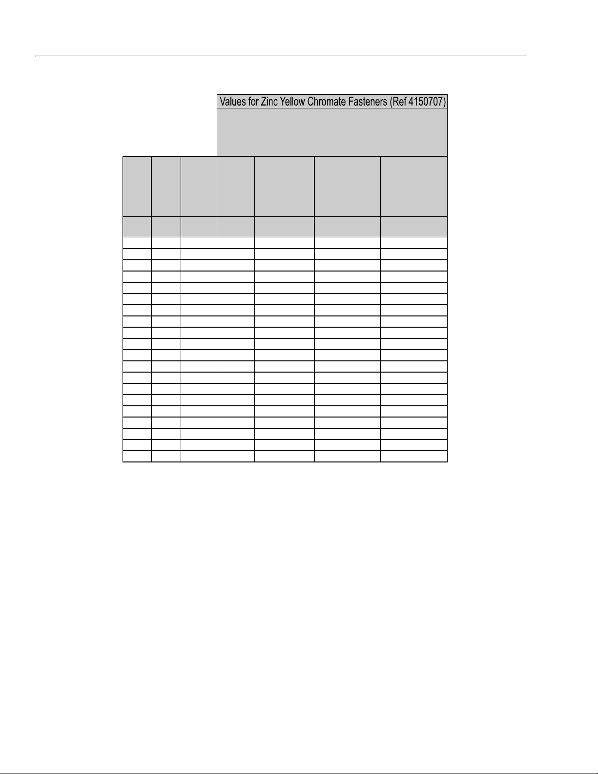
SECTION 1 - SPECIFICATIONS
Size PITCH
Tensile
Stress
Area
Clamp
Load
Torque
(Dry or Loctite®
263
TM
)
K = 0.20
Torque
(Lub OR Loctite®
242
TM
or 271TM OR
Vibra-TITE
TM
111 or
140)
K= 0.18
Torque
(Loctite® 262
TM
OR
Vibra-TITE
TM
131)
K=0.15
Sq mm KN [N.m] [N.m] [N.m]
3 0.5 5.03 3.13
3.5 0.6 6.78 4.22
4 0.7 8.78 5.47
5 0.8 14.20 8.85
6 1 20.10 12.5
7 1 28.90 18.0 25.2 22.7 18.9
8 1.25 36.60 22.8 36.5 32.8 27.4
10 1.5 58.00 36.1 70 65 55
12 1.75 84.30 52.5 125 115 95
14 2 115 71.6 200 180 150
16 2 157 97.8
315 280 235
18 2.5 192 119.5 430 385 325
20 2.5 245 152.5 610 550 460
22 2.5 303 189.0 830 750 625
24 3 353 222.0 1065 960 800
27 3 459 286.0 1545 1390 1160
30 3.5 561 349.5 2095 1885 1575
33 3.5 694 432.5 2855 2570 2140
36 4 817 509.0 3665 3300 2750
42 4.5 1120 698.0 5865 5275 4395
CLASS 10.9 METRIC BOLTS
CLASS 10 METRIC NUTS
CLASS 12.9 SOCKET HEAD CAP SCREWS M3 - M5*
4. CLAMP LOAD LISTED FOR SHCS IS SAME AS GRADE 8 OR CLASS 10.9 A ND DOES NOT
REPRESENT FULL STRENGTH CAPABILITY OF SHCS. IF HIGHER LOAD IS REQUIRED,
ADDITIONAL TESTING IS REQUIRED.
*3. ASSEMBLY USES HARDENED WASHER OR FASTENER IS PLACED AGAINST PLATED
STEEL OR RAW ALUMINUM
NOTES: 1. THESE TORQUE VALUES DO NOT APPLY TO CADMIUM PLATED FASTENERS
2. ALL TORQUE VALUES ARE STATIC TORQUE MEASURED PER STANDARD AUDIT
METHODS TOLERANCE = ±10%
NO. 5000059 REV. J
Figure 1-8. Torque Chart (METRIC Fasteners - Sheet 6 of 7)
1-16 – JLG Lift – 3121827

SECTION 1 - SPECIFICATIONS
Size PITCH
Tensile
Stress
Area
Clamp Load
See Note 4
Torque
(Dry or Loctite®
263
TM
)
K = .17
Torque
(Lub OR Loctite®
242
TM
or 271
TM
OR Vibra-TITE
TM
111 or 140)
K = .16
Torque
(Loctite® 262
TM
OR Vibra-TITE
TM
131)
K = .15
Sq mm kN [N.m] [N.m] [N.m]
30.55.03
3.5 0.6 6.78
40.78.78
50.814.20
6120.1012.5 13 12 11
7128.9018.0 21 20 19
8 1.25 36.60 22.8 31 29 27
10 1.5 58.00 36.1 61 58 54
12 1.75 84.30 52.5 105 100 95
14 2 115 71.6 170 160 150
16 2 157
97.8 265 250 235
18 2.5 192 119.5 365 345 325
20 2.5 245 152.5 520 490 460
22 2.5 303 189.0 705 665 625
24 3 353 220.0 900 845 790
27 3 459 286.0 1315 1235 1160
30 3.5 561 349.5 1780 1680 1575
33 3.5 694 432.5 2425 2285 2140
36 4 817 509.0 3115 2930 2750
42 4.5 1120 698.0 4985 4690 4395
CLASS 12.9 SOCKET HEAD CAP SCREWS
M6 AND ABOVE*
4. CLAMP LOAD LISTED FOR SHCS IS SAME AS GRADE 8 OR CLASS 10.9 AND DOES NOT
REPRESENT FULL STRENG TH CAPABILITY OF SHCS. IF HIGHER LOAD IS REQUIRED,
ADDITIONAL TESTING IS REQUIRED.
*3. ASSEMBLY USES HARDENED WASHER OR FASTENER IS PLACED AGAINST PLATED
STEEL OR RAW ALUMINUM
NOTES: 1. THESE TORQUE VALUES DO NOT APPLY TO CADMIUM PLATED FASTENERS
2. ALL TORQUE VALUES ARE STATIC TORQUE MEASURED PER STANDARD AUDIT
METHODS TOLERANCE = ±10%
NO. 5000059 REV. J
Magni Coating (Ref 4150701)*
3121827 – JLG Lift – 1-17
Figure 1-9. Torque Chart (METRIC Fasteners - Sheet 7 of 7)

SECTION 1 - SPECIFICATIONS
NOTES:
1-18 – JLG Lift – 3121827

SECTION 2. GENERAL
SECTION 2 - GENERAL
2.1 MACHINE PREPARATION, INSPECTION, AND MAINTENANCE
General
This section provides the necessary information needed
by those personnel that are responsible to place the
machine in operation readiness and maintain its safe
operating condition. For maximum service life and safe
operation, ensure that all the necessary inspections and
maintenance have been completed before placing the
machine into service.
Preparation, Inspection, and Maintenance
It is important to establish and conform to a comprehensive inspection and preventive maintenance program. The
following table outlines the periodic machine inspections
and maintenance recommended by JLG Industries, Inc.
Consult your national, regional, or local regulations for further requirements for aerial work platforms. The frequency
of inspections and maintenance must be increased as
environment, severity and frequency of usage requires.
Pre-Start Inspection
It is the User’s or Operator’s primary responsibility to perform a Pre-Start Inspection of the machine prior to use
daily or at each change of operator. Reference the Operator’s and Safety Manual for completion procedures for the
Pre-Start Inspection. The Operator and Safety Manual
must be read in its entirety and understood prior to performing the Pre-Start Inspection.
Pre-Delivery Inspection and Frequent Inspection
The Pre-Delivery Inspection and Frequent Inspection shall
be performed by a qualified JLG equipment mechanic.
JLG Industries, Inc. recognizes a qualified JLG equipment
mechanic as a person who, by possession of a recognized degree, certificate, extensive knowledge, training, or
experience, has successfully demonstrated the ability and
proficiency to service, repair, and maintain the subject
JLG product model.
The Pre-Delivery Inspection and Frequent Inspection procedures are performed in the same manner, but at different times. The Pre-Delivery Inspection shall be performed
prior to each sale, lease, or rental delivery. The Frequent
Inspection shall be accomplished for each machine in service for 3 months or 150 hours (whichever comes first);
out of service for a period of more than 3 months; or when
purchased used. The frequency of this inspection must be
increased as environment, severity and frequency of
usage requires.
Reference the JLG Pre-Delivery and Frequent Inspection
Form and the Inspection and Preventive Maintenance
Schedule for items requiring inspection during the performance of these inspections. Reference the appropriate
areas of this manual for servicing and maintenance procedures.
Annual Machine Inspection
The Annual Machine Inspection must be performed by a
Factory-Certified Service Technician on an annual basis,
no later than thirteen (13) months from the date of the
prior Annual Machine Inspection. JLG Industries, Inc. recognizes a Factory-Certified Service Technician as a person who has successfully completed the JLG Service
Training School for the subject JLG product model. Reference the machine Service and Maintenance Manual and
appropriate JLG inspection form for performance of this
inspection.
Reference the JLG Annual Machine Inspection Form and
the Inspection and Preventive Maintenance Schedule for
items requiring inspection during the performance of this
inspection. Reference the appropriate areas of this manual for servicing and maintenance procedures.
For the purpose of receiving safety-related bulletins, it is
important that JLG Industries, Inc. has updated ownership
information for each machine. When performing each
Annual Machine Inspection, notify JLG Industries, Inc. of
the current machine ownership.
Preventive Maintenance
In conjunction with the specified inspections, maintenance shall be performed by a qualified JLG equipment
mechanic. JLG Industries, Inc. recognizes a qualified JLG
equipment mechanic as a person who, by possession of a
recognized degree, certificate, extensive knowledge, training, or experience, has successfully demonstrated the
ability and proficiency to service, repair, and maintain the
subject JLG product model.
Reference the Preventive Maintenance Schedule and the
appropriate areas of this manual for servicing and maintenance procedures. The frequency of service and maintenance must be increased as environment, severity and
frequency of usage requires.
3121827 – JLG Lift – 2-1

SECTION 2 - GENERAL
Table 2-1. Inspection and Maintenance
Typ e Frequency
Pre-Start Inspection Prior to use each day; or
At each Operator change.
Pre-Delivery
Inspection
Frequent Inspection In service for 3 months or 150 hours, which-
Annual Machine
Inspection
Preventive
Maintenance
Prior to each sale, lease, or
rental delivery.
ever comes first; or
Out of service for a period of more than 3
months; or
Purchased used.
Annually, no later than 13 months from the
date of the prior inspection.
At intervals as specified in the Service and
Maintenance Manual.
2.2 SERVICE AND GUIDELINES
General
The following information is provided to assist you in the
use and application of servicing and maintenance procedures contained in this book.
Safety and Workmanship
Your safety, and that of others, is the first consideration
when engaging in the maintenance of equipment. Always
be conscious of weight. Never attempt to move heavy
parts without the aid of a mechanical device. Do not allow
heavy objects to rest in an unstable position. When raising
a portion of the equipment, ensure that adequate support
is provided.
Cleanliness
1. The most important single item in preserving the
long service life of a machine is to keep dirt and foreign materials out of the vital components. Precautions have been taken to safeguard against this.
Shields, covers, seals, and filters are provided to
keep air, fuel, and oil supplies clean; however, these
items must be maintained on a scheduled basis in
order to function properly.
Primary
Responsibility
User or Operator User or Operator Operator and Safety Manual
Owner, Dealer, or User Qualified JLG
Owner, Dealer, or User Qualified JLG
Owner, Dealer, or User Factory-Trained
Owner, Dealer, or User Qualified JLG
2. At any time when air, fuel, or oil lines are disconnected, clear adjacent areas as well as the openings
and fittings themselves. As soon as a line or component is disconnected, cap or cover all openings to
prevent entry of foreign matter.
3. Clean and inspect all parts during servicing or maintenance, and assure that all passages and openings
are unobstructed. Cover all parts to keep them
clean. Be sure all parts are clean before they are
installed. New parts should remain in their containers until they are ready to be used.
Service
Qualification
Mechanic
Mechanic
Service Technician
(Recommended)
Mechanic
Reference
Service and Maintenance
Manual and applicable JLG
inspection form.
Service and Maintenance
Manual and applicable JLG
inspection form.
Service and Maintenance
Manual and applicable JLG
inspection form.
Service and Maintenance
Manual
Components Removal and Installation
1. Use adjustable lifting devices, whenever possible, if
mechanical assistance is required. All slings (chains,
cables, etc.) should be parallel to each other and as
near perpendicular as possible to top of part being
lifted.
2. Should it be necessary to remove a component on
an angle, keep in mind that the capacity of an eyebolt or similar bracket lessens, as the angle between
the supporting structure and the component
becomes less than 90 degrees.
3. If a part resists removal, check to see whether all
nuts, bolts, cables, brackets, wiring, etc., have been
removed and that no adjacent parts are interfering.
2-2 – JLG Lift – 3121827

SECTION 2 - GENERAL
Component Disassembly and Reassembly
When disassembling or reassembling a component, complete the procedural steps in sequence. Do not partially
disassemble or assemble one part, then start on another.
Always recheck your work to assure that nothing has been
overlooked. Do not make any adjustments, other than
those recommended, without obtaining proper approval.
Pressure-Fit Parts
When assembling pressure-fit parts, use an anti-seize or
molybdenum disulfide base compound to lubricate the
mating surface.
Bearings
1. When a bearing is removed, cover it to keep out dirt
and abrasives. Clean bearings in nonflammable
cleaning solvent and allow to drip dry. Compressed
air can be used but do not spin the bearing.
2. Discard bearings if the races and balls (or rollers)
are pitted, scored, or burned.
3. If bearing is found to be serviceable, apply a light
coat of oil and wrap it in clean (waxed) paper. Do not
unwrap reusable or new bearings until they are
ready to install.
4. Lubricate new or used serviceable bearings before
installation. When pressing a bearing into a retainer
or bore, apply pressure to the outer race. If the bearing is to be installed on a shaft, apply pressure to the
inner race.
Gaskets
Hydraulic Lines and Electrical Wiring
Clearly mark or tag hydraulic lines and electrical wiring, as
well as their receptacles, when disconnecting or removing
them from the unit. This will assure that they are correctly
reinstalled.
Hydraulic System
1. Keep the system clean. If evidence of metal or rubber particles are found in the hydraulic system, drain
and flush the entire system.
2. Disassemble and reassemble parts on clean work
surface. Clean all metal parts with non-flammable
cleaning solvent. Lubricate components, as
required, to aid assembly.
Lubrication
Service applicable components with the amount, type,
and grade of lubricant recommended in this manual, at
the specified intervals. When recommended lubricants are
not available, consult your local supplier for an equivalent
that meets or exceeds the specifications listed.
Battery
Clean battery, using a non-metallic brush and a solution of
baking soda and water. Rinse with clean water. After
cleaning, thoroughly dry battery and coat terminals with
an anti corrosion compound.
Lubrication and Servicing
Components and assemblies requiring lubrication and
servicing are shown in the Lubrication Chart in Section 1.
Check that holes in gaskets align with openings in the
mating parts. If it becomes necessary to hand-fabricate a
gasket, use gasket material or stock of equivalent material
and thickness. Be sure to cut holes in the right location, as
blank gaskets can cause serious system damage.
Bolt Usage and Torque Application
1. Use bolts of proper length. A bolt which is too long
will bottom before the head is tight against its related
part. If a bolt is too short, there will not be enough
thread area to engage and hold the part properly.
When replacing bolts, use only those having the
same specifications of the original, or one which is
equivalent.
2. Unless specific torque requirements are given within
the text, standard torque values should be used on
heat-treated bolts, studs, and steel nuts, in accordance with recommended shop practices. (See
Torque Chart Section 1.)
2.3 LUBRICATION AND INFORMATION
Hydraulic System
1. The primary enemy of a hydraulic system is contamination. Contaminants enter the system by various
means, e.g., using inadequate hydraulic oil, allowing
moisture, grease, filings, sealing components, sand,
etc., to enter when performing maintenance, or by
permitting the pump to cavitate due to insufficient
system warm-up or leaks in the pump supply (suction) lines.
2. The design and manufacturing tolerances of the
component working parts are very close, therefore,
even the smallest amount of dirt or foreign matter
entering a system can cause wear or damage to the
components and generally results in faulty operation. Every precaution must be taken to keep
hydraulic oil clean, including reserve oil in storage.
Hydraulic system filters should be checked,
cleaned, and/or replaced as necessary, at the speci-
3121827 – JLG Lift – 2-3

SECTION 2 - GENERAL
fied intervals required in the Lubrication Chart in
Section 1. Always examine filters for evidence of
metal particles.
3. Cloudy oils indicate a high moisture content which
permits organic growth, resulting in oxidation or corrosion. If this condition occurs, the system must be
drained, flushed, and refilled with clean oil.
4. It is not advisable to mix oils of different brands or
types, as they may not contain the same required
additives or be of comparable viscosities. Good
grade mineral oils, with viscosities suited to the
ambient temperatures in which the machine is operating, are recommended for use.
NOTE: Metal particles may appear in the oil or filters of new
machines due to the wear-in of meshing components.
Hydraulic Oil
1. Refer to Section 1 for recommendations for viscosity
ranges.
2. JLG recommends Mobil DTE-11 hydraulic oil, which
has an SAE viscosity of 10W and a viscosity index of
140.
NOTE: Start-up of hydraulic system with oil temperatures
below -20 degrees F (-29 degrees C) is not recommended. If it is necessary to start the system in a
sub-zero environment, it will be necessary to heat
the oil with a low density, 100VAC heater to a minimum temperature of -20 degrees F (-29 degrees C).
Changing Hydraulic Oil
1. Filter elements must be changed after the first 50
hours of operation and every 300 hours thereafter. If
it is necessary to change the oil, use only those oils
meeting or exceeding the specifications appearing
in this manual. If unable to obtain the same type of
oil supplied with the machine, consult local supplier
for assistance in selecting the proper equivalent.
Avoid mixing petroleum and synthetic base oils.
2. Use every precaution to keep the hydraulic oil clean.
If the oil must be poured from the original container
into another, be sure to clean all possible contaminants from the service container. Always clean the
mesh element of the filter and replace the cartridge
any time the system oil is changed.
3. While the unit is shut down, a good preventive maintenance measure is to make a thorough inspection
of all hydraulic components, lines, fittings, etc., as
well as a functional check of each system, before
placing the machine back in service.
Lubrication Specifications
Specified lubricants, as recommended by the component
manufacturers, are always the best choice, however,
multi-purpose greases usually have the qualities which
meet a variety of single purpose grease requirements.
Should any question arise, regarding the use of greases in
maintenance stock, consult your local supplier for evaluation. Refer to Section 1 for an explanation of the lubricant
key designations appearing in the Lubrication Chart.
2.4 CYLINDER DRIFT TEST
Maximum acceptable cylinder drift is to be measured
using the following methods.
Platform Drift
Measure the drift of the platform to the ground. Lower
booms (if equipped) slightly elevated, upper boom fully
extended with the rated load in the platform and power off.
Maximum allowable drift is 2 inches (5 cm) in 10 minutes.
If the machine does not pass this test, proceed with the
following.
Cylinder Drift
Table 2-2. Cylinder Drift
Cylinder Bore Diameter
inches mm inches mm
3 76.2 0.026 0.66
3.5 89 0.019 0.48
4 101.6 0.015 0.38
5 127 0.009 0.22
6 152.4 0.006 0.15
7 177.8 0.005 0.13
8 203.2 0.0038 0.10
9 228.6 0.0030 0.08
Drift is to be measured at the cylinder rod with a calibrated
dial indicator. The cylinder oil must be at ambient temperature and temperature stabilized.
The cylinder must have the normal load, which is the normal platform load applied.
If the cylinder passes this test, it is acceptable.
NOTE: This information is based on 6 drops per minute cyl-
inder leakage.
Max. Acceptable Drift
in 10 Minutes
2-4 – JLG Lift – 3121827

SECTION 2 - GENERAL
2.5 PINS AND COMPOSITE BEARING REPAIR GUIDELINES
Filament wound bearings.
1. Pinned joints should be disassembled and
inspected if the following occurs:
a. Excessive sloppiness in joints.
b. Noise originating from the joint during operation.
2. Filament wound bearings should be replaced if any
of the following is observed:
a. Frayed or separated fibers on the liner surface.
b. Cracked or damaged liner backing.
c. Bearings that have moved or spun in their hous-
ing.
d. Debris embedded in liner surface.
3. Pins should be replaced if any of the following is
observed (pin should be properly cleaned prior to
inspection):
a. Detectable wear in the bearing area.
b. Flaking, pealing, scoring, or scratches on the pin
surface.
c. Rusting of the pin in the bearing area.
4. Re-assembly of pinned joints using filament wound
bearings.
2.6 WELDING ON JLG EQUIPMENT
NOTE: This instruction applies to repairs, or modifications to
the machine and to welding performed from the
machine on an external structure, or component,
Do the Following When Welding on JLG Equipment
• Disconnect the battery.
• Ground only to structure being welded.
Do NOT Do the Following When Welding on JLG Equipment
• Ground on frame and weld on any other area than the
chassis.
• Ground on turntable and weld on any other area than
the turntable.
• Ground on the platform/support and weld on any other
area than the platform/support.
• Ground on a specific boom section and weld on any
other area than that specific boom section.
• Allow pins, wear pads, wire ropes, bearings, gearing,
seals, valves, electrical wiring, or hoses to be between
the grounding position and the welded area.
a. Housing should be blown out to remove all dirt
and debris...bearings and bearing housings
must be free of all contamination.
b. Bearing / pins should be cleaned with a solvent
to remove all grease and oil...filament wound
bearing are a dry joint and should not be lubricated unless otherwise instructed (i.e. sheave
pins).
c. Pins should be inspected to ensure it is free of
burrs, nicks, and scratches which would damage the bearing during installation and operation.
FAILURE TO COMPLY WITH THE ABOVE REQUIREMENTS MAY
RESULT IN COMPONENT DAMAGE (I.E. ELECTRONIC MODULES,
SWING BEARING, COLLECTOR RING, BOOM WIRE ROPES ETC.)
3121827 – JLG Lift – 2-5

SECTION 2 - GENERAL
Table 2-3. Inspection and Preventive Maintenance Schedule
INTERVAL
2
3
Boom Assembly
AREA
Pre-Start
Inspection
9
1
Maintenance
Weekly
Preventive
Monthly
Preventive
Maintenance
Pre-Delivery
or Frequent
Inspection
Boom Weldments 1,2,4 1,2,4
Hose/Cable Carrier Installations 1,2,9,12 1,2,9,12
Pivot Pins and Pin Retainers 1,2 1,2
Sheaves, Sheave Pins 1,2 1,2
Bearings 1,2 1,2
Wear Pads 1,2 1,2
Covers or Shields 1,2 1,2
Extend/Retract Chain or Cable Systems 1,2,3 1,2,3
Platform Assembly
9
Platform 1,2 1,2
Railing 1,2 1 1,2
Gate 511,5
Floor 1,2 1 1,2
Rotator 9,5 15
Lanyard Anchorage Point 2 1,2,10 1,2,10
Turntable Assembly
9
Swing Bearing or Worm Gear 1,2,14 1,2,3,13,14
Oil Coupling 9
Swing Drive System
Turntable Lock 1,2,5 1,2,5
Hood, Hood Props, Hood Latches 51,2,5
Chassis Assembly
9
Tires 1 16,17 16,17,18 16,17,18
Wheel Nuts/Bolts 115 1515
Wheel Bearings 14,24
Oscillating Axle/Lockout Cylinder Systems 5,8
Outrigger or Extendable Axle Systems 5,8 5,8
Steer Components
Drive Motors
Torque Hubs 11 11
4
Annual
(Yearly)
Inspection
Every 2
Years
2-6 – JLG Lift – 3121827

SECTION 2 - GENERAL
Table 2-3. Inspection and Preventive Maintenance Schedule
INTERVAL
2
3
Inspection
Functions/Controls
AREA
Pre-Start
Inspection
9
1
Maintenance
Weekly
Preventive
Monthly
Preventive
Maintenance
Pre-Delivery
or Frequent
Inspection
Platform Controls 55 66
Ground Controls 55 66
Function Control Locks, Guards, or Detents 1,5 1,5 5 5
Footswitch 1,5 5 5
Emergency Stop Switches (Ground & Platform) 555
Function Limit or Cutout Switch Systems 55
Capacity Indicator 5
Drive Brakes 5
Swing Brakes 5
Boom Synchronization/Sequencing Systems 5
Manual Descent or Auxiliary Power 55
Power System
9
Engine Idle, Throttle, and RPM N/A
Engine Fluids (Oil, Coolant, Fuel) N/A
Air/Fuel Filter 1,7 7 7
Exhaust System 1,9 9 9
Batteries 51,9 19
Battery Fluid 11 11 11
Battery Charger 55
Fuel Reservoir, Cap, and Breather N/A
Hydraulic/Electric System
9
Hydraulic Pumps 1,9 1,2,9
Hydraulic Cylinders 1,9,7 2 1,2,9 1,2,9
Cylinder Attachment Pins and Pin Retainers 1,9 1,2 1,2
Hydraulic Hoses, Lines, and Fittings 1,9 12 1,2,9,12 1,2,9,12
Hydraulic Reservoir, Cap, and Breather 11 1,9 2 1,5 1,5 24
Hydraulic Filter 1,9 7 7
Hydraulic Fluid 11 7,11 7,11
Electrical Connections 12020
Instruments, Gauges, Switches, Lights, Horn 15,23
General
Operators and Safety Manuals in Storage Box 21 21 21
ANSI and EMI Manuals/Handbooks Installed 21
Annual
(Yearly)
4
Every 2
Years
3121827 – JLG Lift – 2-7

SECTION 2 - GENERAL
Table 2-3. Inspection and Preventive Maintenance Schedule
INTERVAL
AREA
Pre-Start
Inspection
1
Maintenance
Weekly
Preventive
Monthly
Preventive
Maintenance
Pre-Delivery
or Frequent
Inspection
2
3
Capacity Decals Installed, Secure, Legible 21 21 21
All Decals/Placards Installed, Secure, Legible 21 21 21
Walk-Around Inspection Performed 21
Annual Machine Inspection Due 21
No Unauthorized Modifications or Additions 21 21
All Relevant Safety Publications Incorporated 21 21
General Structural Condition and Welds 2,4 2,4
All Fasteners, Pins, Shields, and Covers 1,2 1,2
Grease and Lubricate to Specifications 22 22
Function Test of All Systems 21 21 21, 22
Paint and Appearance 77
Stamp Inspection Date on Frame 22
Notify JLG of Machine Ownership 22
Footnotes:
1
Prior to use each day; or at each Operator change
2
Prior to each sale, lease, or delivery
3
In service for 3 months or 150 Hours; or Out of service for 3 months or more; or Purchased use d
4
Annually, no later than 13 months from the date of the prior inspection
Performance Codes:
1 - Check for proper and secure installation
2 - Visual inspection for damage, cracks, distortion or exc essive wear
3 - Check for proper adjustment
4 - Check for cracked or broken welds
5 - Operates Properly
6 - Returns to neutral or "off" position when released
7 - Clean and free of debris
8 - Interlocks function properly
9 - Check for signs of leakage
10 - Decals installed and legible
11 - Check for proper fluid level
12 - Check for chafing and proper routing
13 - Check for proper tolerances
14 - Properly lubricated
15 - Torqued to proper specification
16 - No gouges, excessive wear, or cords showing
17 - Properly inflated and seated around rim
18 - Proper and authorized components
19 - Fully charged
20 - No loose connections, corrosion, or abrasions
21 - Verify
22 - Perform
23 - Sealed Properly
24 - Drain, Clean, Refill
4
Annual
(Yearly)
Inspection
Every 2
Years
2-8 – JLG Lift – 3121827

SECTION 2 - GENERAL
-40 F(-40 C)
-30 F(-34 C)
-20 F(-29 C)
-10 F(-23 C)
0 F(-18 C)
10 F(-12 C)
20 F(-7 C)
30 F(-1 C)
40 F(4 C)
50 F(10 C)
60 F(16 C)
70 F(21 C)
80 F(27 C)
90 F(32 C)
100 F(38 C)
110 F(43 C)
120 F(49 C)
ENGINE
SPECIFICATIONS
ENGINE WILL START AND OPERATE UNAIDED AT THIS
TEMPERATURE WITH THE RECOMMENDED FLUIDS AND A
FULLY CHARGED BATTERY.
AMBIENT AIR
TEMPERATURE
SAE 30
SAE 20SAE 5W-30
SAE 10W-30
SAE 10
NO OPERATION BELOW THIS
AMBIENT TEMPERATUR E
NO OPERATION ABOVE THIS
AMBIENT TEMPERATUR E
(HYD. OIL TANK TEMP.)
IF EITHER OR BOTH CONDITIONS
EXIST JLG HIGHLY RECOMMENDS
THE ADDITION OF A HYDRAULIC
OIL COOLER (CONSULT JLG SERVICE
180° F(82° C)
PROLONGED OPERATION IN
AMBIENT AIR TEMPERATURES
OF 100°F(38°C) OR ABOVE.
EXTENDED DRIVING WITH
HYDRAULIC OIL TANK
TEMPERATURES OF 180°F
(82° C) OR ABOVE.
NO OPERATION BELOW THIS
AMBIENT TEMPERATURE
MOBIL 424 10W-30
HYDRAULIC
SPECIFICATIONS
NO OPERATION ABOVE THIS
AMBIENT TEMPERATURE
DO NOT START UP HYDRAULIC SYSTEM
WITHOUT HEATING AIDS WITH MOBILE 424
HYDRAULIC OIL BELOW THIS TEMPERATURE
DO NOT START UP HYDRAULIC SYSTEM
WITHOUT HEATING AIDS AND COLD WEATHER
HYDRAULIC OIL BELOW THIS TEMPERATURE
EXXON UNIVIS HVI 26
MOBIL DTE 13
NOTE:
1) RECOMMENDATIONS ARE FOR AMBIENT TEMPERATURES
CONSISTANTLY WITHIN SHOWN LIMITS
2) ALL VALUES ARE ASSUMED TO BE AT SEA LEVEL.
-40° F (-40° C)
-30° F (-34° C)
-20° F (-29° C)
-10° F (-23° C)
0° F (-18° C)
10° F (-12° C)
20° F (-7° C)
30° F (-1° C)
40° F (4° C)
50° F (10° C)
60° F (16° C)
70° F (21° C)
80° F (27° C)
90° F (32° C)
100° F (38° C)
110° F (43° C)
120° F (49° C)
AMBIENT AIR
TEMPERATURE
Figure 2-1. Engine Operating Temperature Specifications - Kubota
4150548 E
3121827 – JLG Lift – 2-9

SECTION 2 - GENERAL
NOTES:
2-10 – JLG Lift – 3121827

SECTION 3 - CHASSIS & TURNTABLE
SECTION 3. CHASSIS & TURNTABLE
3.1 TIRES & WHEELS
Tire Inflation
The air pressure for pneumatic tires must be equal to
the air pressure that is stenciled on the side of the JLG
product or rim decal for safe and proper operational
characteristics.
Tire Damage
For pneumatic tires, JLG Industries, Inc. recommends that
when any cut, rip, or tear is discovered that exposes sidewall or tread area cords in the tire, measures must be
taken to remove the JLG product from service immediately. Arrangements must be made for replacement of the
tire or tire assembly.
For polyurethane foam filled tires, JLG Industries, Inc. recommends that when any of the following are discovered,
measures must be taken to remove the JLG product from
service immediately and arrangements must be made for
replacement of the tire or tire assembly.
• a smooth, even cut through the cord plies which
exceeds 3 inches (7.5 cm) in total length
• any tears or rips (ragged edges) in the cord plies which
exceeds 1 inch (2.5 cm) in any direction
• any punctures which exceed 1 inch in diameter
• any damage to the bead area cords of the tire
If a tire is damaged but is within the above noted criteria,
the tire must be inspected on a daily basis to insure the
damage has not propagated beyond the allowable criteria.
Tire Replacement
JLG recommends a replacement tire be the same size, ply
and brand as originally installed on the machine. Please
refer to the JLG Parts Manual for the part number of the
approved tires for a particular machine model. If not using
a JLG approved replacement tire, we recommend that
replacement tires have the following characteristics:
Unless specifically approved by JLG Industries Inc. do not
replace a foam filled or ballast filled tire assembly with a
pneumatic tire. When selecting and installing a replacement tire, ensure that all tires are inflated to the pressure
recommended by JLG. Due to size variations between
tire brands, both tires on the same axle should be the
same.
Wheel Replacement
The rims installed on each product model have been
designed for stability requirements which consist of track
width, tire pressure, and load capacity. Size changes such
as rim width, center piece location, larger or smaller diameter, etc., without written factory recommendations, may
result in an unsafe condition regarding stability.
Wheel Installation
It is extremely important to apply and maintain proper
wheel mounting torque.
WHEEL NUTS MUST BE INSTALLED AND MAINTAINED AT THE
PROPER TORQUE TO PREVENT LOOSE WHEELS, BROKEN
STUDS, AND POSSIBLE DANGEROUS SEPARATION OF WHEEL
FROM THE AXLE. BE SURE TO USE ONLY THE NUTS MATCHED
TO THE CONE ANGLE OF THE WHEEL.
Tighten the lug nuts to the proper torque to prevent
wheels from coming loose. Use a torque wrench to tighten
the fasteners. If you do not have a torque wrench, tighten
the fasteners with a lug wrench, then immediately have a
service garage or dealer tighten the lug nuts to the proper
torque. Over-tightening will result in breaking the studs or
permanently deforming the mounting stud holes in the
wheels. The proper procedure for attaching wheels is as
follows:
1. Start all nuts by hand to prevent cross threading. DO
NOT use a lubricant on threads or nuts.
• Equal or greater ply/load rating and size of original
• Tire tread contact width equal or greater than original
• Wheel diameter, width, and offset dimensions equal to
the original
• Approved for the application by the tire manufacturer
(including inflation pressure and maximum tire load)
3121827 – JLG Lift – 3-1

SECTION 3 - CHASSIS & TURNTABLE
2. Tighten nuts in the following sequence:
3. The tightening of the nuts should be done in stages.
Following the recommended sequence, tighten nuts
per wheel torque chart.
Table 3-1. Wheel Torque Chart
TORQUE SEQUENCE
1st Stage 2nd Stage 3rd Stage
40 ft. lbs.
(55 Nm)
4. Wheel nuts should be torqued after first 50 hours of
operation and after each wheel removal. Check
torque every 3 months or 150 hours of operation.
100 ft. lbs.
(130 Nm)
170 ft. lbs.
(255 Nm)
3.2 SPINDLE
5. Check the unit for end play by moving the hub up &
down parallel along the centerline of the spindle. If
you can feel excessive end play (over the 0.010"
[0.25 mm] specification), recheck the nut to see
what is causing the excessive end play. Keep in
mind that there can be some movement and still be
within the 0.010" (0.25 mm) maximum specification.
If there is no way of getting the excessive end play
out by using your fingers, a socket or wrench may
have to be used to set the end play.
6. The units should be checked visually to make sure
the cotter pins are installed and that the correct
components have been used. Each unit must also
be checked for the proper feel to make sure there
isn’t excessive end play and the hubs turn freely.
7. Insert the dust cap and check to make sure the cotter pin is not going to interfere. Cap must be pressed
all the way down. The unit should be checked again
to assure it spins freely after the dust cap is installed.
Specifications
The end play specification is 0.001”/0.010" (0.025 / 0.254
mm) for all units.
Checking
The end play is checked by clamping the spindle in a fixture or vise and moving the hub parallel to the spindle
centerline without rocking the hub. If the end play is set
properly the following should apply:
1. Hub should rotate freely when spun by hand.
2. The hub should not be noticeably loose when
moved parallel with spindle centerline.
Setting Wheel Bearing End Play
BE SURE NOT TO OVER-TIGHTEN THE SPINDLE NUT.
1. Tighten the spindle nut to assure the bearings are
properly seated.
2. Loosen the spindle nut completely until the nut can
be turned by hand.
3. Tighten the spindle nut by hand using a socket without rotating the hub.
4. If the cotter pin can be assembled with the spindle
nut finger tight, insert cotter pin without backing the
nut off. If the cotter pin cannot be assembled with
the spindle nut hand tight, tighten the spindle nut to
the nearest available slot and insert cotter pin. If
more than ½ of the cotter pin hole in the spindle can
be seen in a slot, back nut off to nearest slot and
insert pin.
Greasing Requirements
Hub assemblies shall have grease packed in the bearings
via an appropriate greasing spindle or by hand. In either
method, the bearing must be greased so the grease is
forced thru the entire bearing cavity and thru the rollers of
both inner and outer bearings.
Dust or grease caps used shall have grease applied to the
inside of the cap.
The bearing cavity shall be filled 50 - 80% full of grease on
all applications.
Dust or grease caps shall also be filled 10-20% full of
grease on all applications prior to final assembly.
Visually verify that grease has flowed thru all rollers of the
inner and outer bearings.
3-2 – JLG Lift – 3121827

SECTION 3 - CHASSIS & TURNTABLE
1. Dust Cap
2. Cotter Pin
3. Spindle Nut
4. Spindle Washer
5. Stud Nut
6. Bearing Cone
7. Hub
8. Bearing Cone
9. Seal
10. Spindle
Figure 3-3. Spindle Assembly
3121827 – JLG Lift – 3-3

SECTION 3 - CHASSIS & TURNTABLE
3.3 DRIVE HUB (PART NO. 2780236)
The final drive consists of two planetary stages with an
integrated disconnect mechanism. Each stage incorporates a set of matched planetary gears, which provide an
equal load distribution. All torque transmitting components are made of forged quenched and tempered highalloy steels. External gears are carburized. Precision roller
bearings support the sprocket or wheel loads. A shaft seal
protects the unit against contamination.
Dissembling
1. Position drive so that one of the fill holes is at the
bottom of the end cover and drain the oil.
2. Remove all bolts holding the motor and Remove
motor from drive.
3. Compress the disc (59) using a simple fixture or
other suitable device.
4. Remove snap ring (66) and release pressure on disc
until loose. Remove tool and disc.
5. Remove the spring (55) from the input shaft (44).
6. Turn unit so that cover (8) is in the up position.
7. Remove the screw plugs (22) and seal rings (21).
8. Remove snap rings (34), and remove the cover unit
(8) from drive.
9. Remove “o” ring (33).
10. Remove the first stage planetary assembly (7).
15. Inspect the planetary stage assemblies as complete
units. Thoroughly clean and check both the gearing
and the bearings for damage and apply new oil. If
the gears or bearings need replacing, they must be
replaced as complete sets.
16. The first stage planetary gears (2) must be changed
in sets of three pieces.
17. The first stage planetary gears (2) must be changed
as a complete set of three and JLG recommends
changing the sun gear shaft (43) along with this set
of planets.
18. The second stage planetary bearings (11) must be
replaced in sets of four pieces.
19. The second stage planetary gears (1) must be
changed as a complete set of four and JLG recommends changing the sun gear (3) along with this set
of planets.
11. Remove hex bolts (23).
12. Remove ring gear (30) and “o” ring (19).
13. Remove snap rings (15).
14. Pull off planet gears (1) together with cylindrical
roller bearings (11) from spindle (60).
NOTE: Further disassembly of the hub is discouraged. rein-
stallation of the shaft nut (4) requires a special tool
and a torque of 626 ft./ lbs. (876 Nm) for proper reassembly. These components Will Fail if not properly
reassembled.
3-4 – JLG Lift – 3121827

SECTION 3 - CHASSIS & TURNTABLE
Disassembly
1. Loosen and remove hex head bolts (53) to remove
cover (51).
2. Remove shaft rod (56) and “o” ring (54).
3. Remove sleeve (52).
Disassembly of the first stage planetary assembly (7)
1. Push sun gear shaft (43) out of the first stage.
2. Remove snap rings (14).
3. Press planet pins (5) out of the planet gears (2).
4. Pull cylindrical roller bearing (10) out of the planet
gears (2).
5. Remove snap ring (16) from sun gear (3) and
Remove planet carrier (7) from sun gear (3).
6. Remove thrust washer (49).
Disassembly of second stage planet gears (1)
1. Press cylindrical roller bearings out of planet gears
(1).
Assembly of first stage planetary assembly (7)
1. Pre-freeze planet pins (5) and install into planet carrier (7).
2. Install planet carrier (7) together with planet pins (5)
on sun gear (3), and install snap ring (16).
3. Pre-heat thrust washer (49) and Install onto sun gear
shaft (43).
4. Put sun gear shaft (43) into sun gear (3).
5. Pre-heat support disk (17) and install onto planet
pins (5).
6. Pre-heat cylindrical roller bearings (10) and install
onto planet pins (5) and fix bearings with snap rings
(14).
Assembly of end cover unit (8)
1. Press sleeve (52) into cover (8).
2. Install “o” ring (54) into groove of cover (8).
3. Install shift rod (56) into cover (8).
4. Install the cover (51) into cover (8) and fix cover (51)
with hex bolts (53). Tighten bolts with torque wrench
to 6.3 ft. lbs. (8.5 Nm).
3121827 – JLG Lift – 3-5

SECTION 3 - CHASSIS & TURNTABLE
Final Assembly
1. Install thrust washer (29) in spindle (60).
2. Install “o” ring (19) into groove of support ring (6).
3. Install planet gears (1) onto planet pins which are
part of spindle (60).
4. Install snap rings (15) on planet pins of spindle (60)
in order to fix the planet gears (1).
5. Put ring gear (30) onto support ring (6) and fix ring
gear (30) with hex head bolts (23). Tighten bolts with
torque wrench to 15.5 ft. lbs.(21.1 Nm).
6. Insert the first stage planetary assembly (7) into
drive.
7. Install “o” ring (33) in groove of ring gear (30).
8. Install end the cover unit (8) on shoulder ring gear
(30) and fix with snap ring (34).
9. Install seal rings (22) and screw plugs (21).
10. Before installation of motor, CHECK THAT THERE IS
1-2mm OF CLEARANCE BETWEEN THE MOTOR
SPLINE SHAFT SHOULDER AND THE COUPLER
(62).
11. Install the motor and reconnect hydraulic lines.
12. Roll motor so that one fill plug is at 12 o’clock posi-
tion, and the other is at 3 o’clock. Fill to bottom of 3
o’ clock plug with gear oil. reinstall plugs
Initial Start-up And After Repairs
Before operating the machine, make sure that the drive is
filled with clean oil, approximately.2 us gallons(.8 L). An
accurate oil level is determined by the oil level plug, which
should be removed before oil fill.
With the gear case filled to their proper levels, start the
machine and allow sufficient time for run-in at moderate
pressure and speed before running at full speed. After 4
hours of operation, recheck oil level.
Maintenance
Daily: - Check for oil leakage
Weekly: - Check oil level
Monthly: - Check mounting bolt torque
Oil Change Interval-Gear Drive
1. Perform the first oil change after approximately 150
hours.
2. Subsequent changes, every 1500 hours or annually,
whichever occurs first.
NOTE: flush the drive before filling with new oil.
Setting of Tapered Roller Bearings
NOTE: The numbers in parentheses ( ) reference the figure
Drive Hub- Cutaway.
1. De-grease threads of the spindle (60) and shaft nut
(4).
2. Spin the shaft nut onto spindle by hand to insure the
threads are in good condition.
3. Apply Loctite 270 evenly to threads of the shaft nut.
4. Rotate the support ring repeatedly in one direction
only, during setting of the tapered roller bearings.
5. Tighten shaft nut to 626 ft. lbs. (850 Nm).
6. Do not use the hub for 24 hours to allow the Loctite
to harden properly.
7. Do not fill with oil for 24 hours to allow the Loctite to
harden properly.
Securing of the Shaft Nut
1. After proper bearing setting is completed, use a suitable punch to place ball (24) 0.04 to 0.05 inches (1.1
to 1.3 mm) into the spindle thread. Then set ball (24)
in position by punching in expander (25).
3-6 – JLG Lift – 3121827

SECTION 3 - CHASSIS & TURNTABLE
1. Planet Gear
2. Planet Gear
3. Sun Gear
4. Shaft Nut
5. Planet Bolt
6. Support Ring
7. Planet Carrier
8. Cover
9. (Not Used)
10. Roller Bearing
11. Roller Bearing
12. Tapered Roller Bearing
13. (Not Used)
14. Retaining Ring
15. Retaining Ring
16. Retaining Ring
17. Support Disc
18. (Not Used)
19. O Ring
20. Ring Seal
21. Screw Plug
22. Seal Ring
23. Bolt
24. Ball
25. Expander
26. thru 28. (Not Used)
29. Washer
30. Ring Gear
31. thru 32. (Not Used)
33. O Ring
34. Spring
35. thru 42. (Not Used)
43. Sun Gear Shaft
44. Input Shaft
45. thru 48. (Not Used)
49. Washer
50. (Not Used)
51. Cover
52. Disc
53. Bolt
54. O Ring
55. Pressure Spring
56. Shaft Rod
57. thru 58. (Not Used)
59. Rotor Disc
60. Spindle
61. (Not Used)
62. Coupler
63. thru 65.(Not Used)
66. Retaining Ring
67. thru 80. (Not Used)
81. Ball Bearing
82. Retaining Ring
83. Retaining Ring
84. thru 87. (Not Used)
88. Wheel Stud
Figure 3-1. Drive Hub - Cutaway
3121827 – JLG Lift – 3-7

SECTION 3 - CHASSIS & TURNTABLE
3.4 DRIVE BRAKE - MICO
Disassembly
1. Remove pressure plate (3) from cover (21) by
removing the capscrews (1) and washers (2).
PRESSURE PLATE IS UNDER SPRING TENSION OF APPROXIMATELY 1500 LBS (680 KGF). THE FOUR CAP SCREWS SHOULD
BE LOOSENED EVENLY TO RELIEVE THIS FORCE. IF A HYDRAULIC PRESS IS AVAILABLE, 3000 LBS (1361 KGF) MINIMUM, THE
PRESSURE PLATE CAN BE HELD IN POSITION WHILE REMOVING
THE CAP SCREWS AND WASHERS
2. Remove case seal (4) from cover (21).
3. Remove piston (7) from pressure plate (3).
4. Remove o-ring (5), back-up ring (6), o-ring (8) and
back-up ring (9) from piston (7).
IF THE SENSOR RING (12) IS DAMAGED OR NEEDS REPLACED,
THE ENTIRE BRAKE MUST BE REPLACED AS A UNIT. THE SENSOR RING IS NOT AVAILABLE AS A SERVICE PART.
5. Remove stack assembly, consisting of stator disc
(11), sensor ring (12), rotor disc (13), and plate (14)
from cover (21).
6. Remove dowel pins (20), springs (15) and spring
retainer (16) from cover (21).
NOTE: Note number and pattern of springs for reassembly
purposes.
4. Install shaft assembly and retaining ring (17) in
cover (21).
NOTE: Be sure to use the same number of springs and
spring pattern as recorded during disassembly. This
should be five red springs evenly spaced.
5. Install dowel pins (20), spring retainer (16) and
springs (5) in cover plate (21).
6. Position plate (14) on springs (15). NOTE: Disc (13
&11) and plate (14) must remain dry during
installation. No oil residue must be allowed to
contaminate disc surfaces.
7. Place a new rotor disc (13), including speed sensor
ring (12), on the shaft (10) until it contacts the plate
(14). Install stator disc (11).
8. Install new o-ring (5), new back-up ring (6), new oring (8) and new back-up ring (9) on piston (7). Note
order of o-rings and backup rings. Insert piston (7)
into pressure plate (3). Be careful not to shear orings or back-up rings.
9. Install new case seal (4) in cover (21).
10. Position pressure plate (3) on cover (21) aligning
dowel pins (20) with holes in pressure plate.
NOTE: A hydraulic press will simplify installation of pressure
plate on cover. Clamp pressure plate in position
while tightening the cap screws.
11. Install capscrews (1) and washers (2) and tighten
evenly to draw pressure plate (3) to cover (21).
Torque capscrews to 55 ft.lbs. (74.6 Nm).
7. Remove retaining ring (17) from cover (21).
8. Remove shaft (10) by pressing or using a soft mallet
on male end of the shaft.
9. Remove retaining ring (19) and bearing (18) from
shaft (10).
10. Press rotary oil seal (20) from cover (18).
Assembly
NOTE: Lubricate all rubber components from the repair kit
with clean type fluid used in the system.
1. Clean all parts thoroughly before assembly.
2. Press new rotary seal (22) into cover (21). Note
direction of seal
3. Install new bearing (18) and retaining ring (19) on
shaft (10).
IF HYDROSTATIC BENCH TESTING IS PERFORMED ON THE
BRAKE ASSEMBLY, RELEASE PRESSURE SHOULD NOT EXCEED
2000 PSI (137.9 BAR) UNLESS TWO ADDITIONAL BOLTS ARE
USED FOR SUPPLEMENTAL CLAMPING.
Bleeding
I
1. Install brake in system and connect pressure lines.
2. Bleed pressure release section of brake by pressur-
izing side inlet port and allowing air to escape from
top port. Pressure should not exceed 100 psi (6.9
bar) during bleeding.
3. Apply sufficient pressure to release brake and check
for proper operation in system.
3-8 – JLG Lift – 3121827

23
22
19
21
18
17
16
15
20
12
11
10
9
8
7
6
5
4
23
3
1
13142
1. Capscrew
2. Washer
3. Pressure Plate
4. Case Seal
5. O-ring
6. Backup Ring
7. Piston
8. O-ring
9. Backup Ring
10. Shaft
11. Stator Disc
12. Sensor Ring
13. Rotor Disc
14. Plate
15. Spring
16. Spring Retainer
17. Retaining Ring
18. Bearing
19. Retaining Ring
20. Dowel Pin
21. Cover
22. Rotary Oil Seal
23. Gasket
Figure 3-2. Drive Brake
NOTE: The speed sensor port in the cover (21)
should be 180° from the brake release
port in the pressure plate (3).
SECTION 3 - CHASSIS & TURNTABLE
3121827 – JLG Lift – 3-9

SECTION 3 - CHASSIS & TURNTABLE
Table 3-2. Drive Brake Diagnosis
Problem Cause Explanation
Brake slips Excessive pressure In hydraulic
system
Oil In brake if designed for dry
use
Springs broken or have taken a
permanent set
Brake drags or runs
hot
Brake will not release Stuck or clogged valve Brakes are designed to come on when system pres-
Low actuation pressure T he brake should be pressurized to minimum of
Bearing failure If the bearing should fall. a large amount of drag can
Bad o-rings Release piston will not hold pressure, brake will not
If there is back pressure in the actuation line of the
brake, holding torque will be reduced.
Wet linings generate 67% of the dry torque rating. If
the brake has oil In it, check the type of oil hydraulic
or gearbox.
1. Gearbox oil
2. Hydraulic oil
Broken or set springs can cause reduced torque rare occurrence.
1.38 bar (20 psi) over the full release pressure under
normal operating conditions. Lower pressures will
cause the brake to drag thus ge nerating heat.
be generated.
sure drops below stated release pressu re. If pressure cannot get to brake, the brake will not release .
release.
Corrective
Action
Check filters. hose size, restrictions
in other hydraulic components.
Replace oil seal in brake. Check
motor seal. Check piston seals.
Note: Internal components will
need to be inspected, cleaned, and
replaced as required.
See spring replacement
Place pressure gauge in bleed port
& check pressure with system on.
Replace bearing.
Place pressure gauge in bleed por t
- check for adequate pressure.
Replace defective line or component.
Replace o-rings.
Discs frozen These brakes are designed for only limi ted dynamic
braking. A severe emergency stop or prolonged
reduced release pressure operation may result in
this type of damage.
Replace disc stack.
3-10 – JLG Lift – 3121827

SECTION 3 - CHASSIS & TURNTABLE
3.5 SPEED SENSOR ADJUSTMENT
For proper drive operation, the speed sensors must be
properly installed and adjusted. The sensor operates on a
leading pulse to show direction. If installed wrong, the
sensor will not be able to sense the proper direction.
IF BOTH SPEED SENSORS ARE INSTALLED WRONG, THE CONTROLLER WILL THINK THE MACHINE IS ON A HILL AND WILL GO
INTO FULL SPEED MODE IMMEDIATELY WHEN DRIVE IS
SELECTED. THE MACHINE WILL NOT STOP UNLESS THE FOOTSWITCH IS RELEASED OR THE EMS IS PUSHED IN.
Adjustment Procedure
1. Back off the locking nut and o-ring.
2. Thread the sensor in until it bottoms out (don’t use
excessive force).
3. Back-off 1-2 turns and align the notch with the axis
of the brake. Refer to Figure 3-3., Speed Sensor Orientation.
4. Use a 1/2” wrench to hold the sensor and a 11/16”
wrench to snug the lock nut to the brake.
IF ONLY ONE SENSOR IS INSTALLED WRONG, THE CONTROLLER SENSES A PROBLEM AND THE MACHINE WILL ONLY DRIVE
AT CREEP SPEED. IF BOTH SENSORS ARE ADJUSTED TOO FAR
OUT, THE CONTROL SYSTEM CONTROLLER WILL NOT DRIVE
THE MACHINE.
3121827 – JLG Lift – 3-11

SECTION 3 - CHASSIS & TURNTABLE
Figure 3-3. Speed Sensor Orientation
3-12 – JLG Lift – 3121827

SECTION 3 - CHASSIS & TURNTABLE
Figure 3-4. Frame Mounted Electrical Components - Sheet 1 of 2
3121827 – JLG Lift – 3-13

SECTION 3 - CHASSIS & TURNTABLE
Figure 3-5. Frame Mounted Electrical Components - Sheet 2 of 2
3-14 – JLG Lift – 3121827

SECTION 3 - CHASSIS & TURNTABLE
Should read 0-7 Volts. Anything o
v
e
r 7
volts should flash Err
or
Code 7-7, Open Pump Circuit. If
the voltage is
high,
check for
corrosion, a dirty pump motor, or
ba
d
brushes
.
The drive system should show 48 volts w ith
the main contactor closed and 35 volts with
the main contactor open.
These voltage checks should be performed
w ith th e ma ch in e p owe r e d u p a n d th e ma in
contactor o pen .
Figure 3-6. Voltage Checks
3121827 – JLG Lift – 3-15

SECTION 3 - CHASSIS & TURNTABLE
Speed Sensor Installation Verification
The motor controller averages the readings from the right
and left speed sensors and therefor, it can be difficult to
detect if the speed sensors are adjusted properly. When
the positrac keeps coming in and out while on level surfaces, this is a sure indication that one of the speed sensors is not adjusted properly.
The worse case condition of speed sensor installation
occurs when both sensors are installed in a manner that
allows them to indicate the exact opposite direction that
the machine is traveling. This situation causes the controller to believe that the machine is rolling in opposite direction than that selected by the operator. The controllers
reaction to this situation is to put more power into the
drive motors to attempt to overcome the fact that it
believes the machine is rolling backwards. This presents
itself as uncontrolled movement in the direction selected
by the operator until the controller recognizes that it is
placing maximum power in the motors and the controller
and the speed sensors are still reporting movement in the
opposite direction. The controller responds by shutting
down drive and reporting flash code 5/5- Vehicle Runaway
Check Speed Encoders.
If either speed sensor is disconnected or faulty, the controller will recognize this condition and immediately report
flash code 5/5 - Left or Right speed Encoder Faulty.
Verification w/ Analyzer Procedure
Below is a procedure using the Analyzer that will verify
that the speed sensors are installed correctly.
THIS PROCEDURE REQUIRES A LARGE SPACE CLEAR OF
OBSTRUCTIONS. THE OPERATOR SHOULD BE FAMILIAR WITH
JLG EQUIPMENT AND BE PREPARED TO USE THE FOOTSWITCH
TO STOP THE MACHINE. READ AND UNDERSTAND THIS ENTIRE
PROCEDURE PRIOR TO BEGINNING.
1. Before beginning this procedure, insure that there is
at least 10 ft. (3m)in front and back of machine. Be
sure that all other personnel stand clear of the
machine during this procedure.
2. Unplug the left speed sensor from the posi-trac tilt
module.
3. Power up the machine in platform mode and plug in
the Analyzer in the platform.
4. Use the right and left cursor keys on the analyzer to
highlight “DIAGNOSTICS” and press enter.
5. Use the right and left cursor keys on the analyzer to
highlight “DRIVE” and press enter.
6. Use the right and left cursor keys to display ’SPEED
0%” on the analyzer.
7. While watching the analyzer display, select drive forward. Be ready to remove your foot from the foot
switch if the machine lunges forward.
8. The analyzer display should read the following if the
RIGHT speed sensor is adjusted properly: “SPEED
20% FWD”.
9. If the speed sensor is adjusted improperly, the analyzer will display “SPEED 20% REV” and the
machine will lunge forward.
10. Adjust the right speed sensor using the preceding
Adjustment Procedure until the analyzer displays
“SPEED 20% FWD” when forward is selected at the
platform. The percentage displayed is not critical,
just the direction.
11. After obtaining the display in step 10, operate the
machine in both forward and reverse directions. The
machine should be controllable in both directions
and will only drive at a maximum of creep speed.
The display on the analyzer should match the direction selected.
12. After completing adjustment of the right sensor, plug
the left sensor into the posi-tilt module.
13. Unplug the right sensor from the power module.
14. Power up the machine in platform mode and plug in
the analyzer in the platform.
15. Use the right left cursor keys on the analyzer to highlight diagnostics and press enter.
16. Use the right and left cursor keys on the analyzer to
highlight drive and press enter.
17. Use the right and left cursor keys to display “speed
0%” ON THE ANALYZER.
3-16 – JLG Lift – 3121827

SECTION 3 - CHASSIS & TURNTABLE
18. While watching the analyzer display, select drive forward. Be ready to remove your foot from the foot
switch if the machine lunges forward.
19. The analyzer display should read the following if the
left speed sensor is adjusted properly: “SPEED 20%
FWD”.
20. If the left speed sensor is adjusted improperly, the
analyzer will display “SPEED 20% REV”, and the
machine will lunge forward.
21. Adjust the left speed sensor using the preceding
Adjustment Procedure until the analyzer displays
“SPEED 20% FWD” when forward is selected in the
platform. The percentage displayed is not critical,
just the direction.
22. After obtaining the display in step 10, operate the
machine in both the forward and reverse directions.
The machine should be controllable in both directions and will only drive at a maximum of creep
speed. The display on the analyzer should match
the direction selected.
23. Plug in the right sensor to the power module.
24. Test the machine. The machine should now have
maximum drive speed available in both directions
and should be controllable in both directions. The
analyzer display should match the direction
selected.
3121827 – JLG Lift – 3-17

SECTION 3 - CHASSIS & TURNTABLE
Figure 3-7. Steering Components and Spindles
3-18 – JLG Lift – 3121827

SECTION 3 - CHASSIS & TURNTABLE
Figure 3-8. Drive Components
3.6 POSITRAC/TILT MODULE
When installing a new positrac/tilt module, always ensure
that it is calibrated using the JLG Control System analyzer
before operating the machine. Refer to JLG Control System Analyzer Kit instructions. Use a standard bubble level
in two different directions to ensure that the machine’s
frame is level prior to installing the new positrac/tilt module.
1. Place the machine on a flat, level surface. Check for
level by placing a bubble level on the frame in both
directions.
2. Plug in the analyzer (Analyzer - p/n 1600244, Cable p/n 1600633) into port J9 on the power module or
port J1 on the platform module.
3. Use the right arrow key to curse over to “ACCESS
LEVEL 2". Depress Enter.
4. Use Up/Down arrow keys to enter the following
password “33271”. Depress Enter.
5. Use the right arrow key to curse over to “LEVEL
VEHICLE”. Depress Enter. Depress Enter again.
6. Verify that the tilt reading is now “0.0; 0.0".
TO ASSURE PROPER OPERATION, THE MACHINE MUST BE LEVEL
WHEN INSTALLING AND CALIBRATING A NEW POSITRAC/TILT
MODULE.
3121827 – JLG Lift – 3-19

SECTION 3 - CHASSIS & TURNTABLE
Figure 3-9. Tilt Sensor Location
3-20 – JLG Lift – 3121827

3.7 SWING MOTOR - S/N 0300135649 TO
Figure 3-10. Swing Motor - Cutaway
PRESENT
SECTION 3 - CHASSIS & TURNTABLE
IF THE HYDRAULIC SYSTEM FLUID BECOMES OVERHEATED [IN
EXCESS OF 200°F (93.3°C)], SEALS IN THE SYSTEM CAN
SHRINK, HARDEN OR CRACK, THUS LOSING THEIR SEALING
ABILITY.
3121827 – JLG Lift – 3-21

SECTION 3 - CHASSIS & TURNTABLE
Table 3-3. Swing Motor Troubleshooting
Trouble Cause Remedy
Oil Leakage 1. Hose fittings loose, worn or damaged.
Check & replace damaged fittings or "O" Rings. Torque to
manufacturers specifications.
2. Oil seal rings (4) deteriorated by excess heat.
3. Special bolt (1, 1 A, 1B or 1C) loose or its sealing
area deteriorated by corrosion.
4. Internal shaft seal (16) worn or damaged.
5. Worn coupling shaft (12) and internal seal (16).
Significant loss of speed under load 1. Lack of sufficient oil supply
2. High internal motor leakage
3. Severely worn or damaged internal splines.
4. Excessive heat.
Low mechanical efficiency or undue
high pressure required to operate unit
1. Line blockage
2. Internal interference
Replace oil seal rings by disassembling unit.
(a) Loosen then tighten single bolt to torque specification.
(b) Replace bolt.
Replace seal. Disassembly of motor unit necessary.
Replace coupling shaft and seal by disassembling unit.
(a) Check for faulty relief valve and adjust or replace as
required.
(b) Check for and repair worn pump.
(c) Check for and use correct oil for temperature of operation.
Replace worn rotor set by disassembling unit.
Replace rotor set, drive link and coupling shaft by disassembling unit.
Locate excessive heat source (usually a restriction) in the
system and correct the condition.
Locate blockage source and repair or replace.
Disassemble unit, identify and remedy cause and repair,
replacing parts as necessary.
3. Lack of pumping pressure
4. Excessive binding or loading in system external to
motor unit.
Check for and repair worn pump.
Locate source and eliminate cause.
3-22 – JLG Lift – 3121827

SECTION 3 - CHASSIS & TURNTABLE
123
4
4
4
8
8
8E
8A
8C
8B
4
8D
9
4
4
5
7
6
10
12
13
14
14
15
16
25
17
18
19
20
1. Bolt
2. End Cover
3. Seal Ring
4. Seal Ring
5. Commutator
6. Commutator Ring
7. Manifold
8. Rotor Set
8A. Rotor
8B. Stator Half
8C. Stator Vane
8D. Stator Half
9. Wear Plate
10. Drive Link
11. Thrust Bearing
12. Coupling Shaft
13. Inner Bushing
14. Thrust Washer
15. Thrust Bearing
16. Seal
17. Backup Ring
18. Housing
19. Outer Bushing
20. Dirt & Water Seal
21. Not Used
22. Not Used
23. Not Used
24. Not Used
25. Backup Washer
Figure 3-11. Swing Motor - Exploded View
3121827 – JLG Lift – 3-23

SECTION 3 - CHASSIS & TURNTABLE
Preparation Before Disassembly
• Before you disassemble the motor unit or any of its
components read this entire section. It provides important information on parts and procedures you will need
to know to service the motor.
• Thoroughly clean off all outside dirt, especially from
around fittings and hose connections, before disconnecting and removing the motor. Remove rust or corrosion from coupling shaft.
• Remove coupling shaft connections and hose fittings
and immediately plug port holes and fluid lines.
• Remove the motor from system, drain it of fluid and
take it to a clean work surface.
• Clean and dry the motor before you start to disassemble the unit.
• As you disassemble the motor clean all parts, except
seals, in clean petroleum-based solvent, and blow
them dry.
PETROLEUM-BASE SOLVENTS ARE FLAMMABLE. BE EXTREMELY
CAREFUL WHEN USING ANY SOLVENT. EVEN A SMALL EXPLOSION OR FIRE COULD CAUSE INJURY OR DEATH.
WEAR EYE PROTECTION AND BE SURE TO COMPLY WITH OSHA
OR OTHER MAXIMUM AIR PRESSURE REQUIREMENTS.
NEVER STEAM OR HIGH PRESSURE WASH HYDRAULIC COMPONENTS. DO NOT FORCE OR ABUSE CLOSELY FITTED PARTS.
Disassembly and Inspection
1. Place the motor in a soft jawed vice, with coupling
shaft (12) pointed down and the vise jaws clamping
firmly on the sides of the housing (18) mounting
flange or port bosses. Remove manifold port ORings if applicable.
IF THE MOTOR IS NOT FIRMLY HELD IN THE VISE, IT COULD BE
DISLODGED DURING THE SERVICE PROCEDURES, CAUSING
INJURY.
2. Scribe an alignment mark down and across the
motor components from end cover (2) to housing
(18) to facilitate reassembly orientation where
required.
• Keep parts separate to avoid nicks and burrs.
• Discard all seals and seal rings as they are removed
from the motor. Replace all seals, seal rings and any
damaged or worn parts with OEM approved service
parts.
3-24 – JLG Lift – 3121827

3. Remove the special ring head bolts (1) using an
appropriate 1/2 or 9/16 inch size socket. Inspect
bolts for damaged threads, or sealing rings, under
the bolt head. Replace damaged bolts.
SECTION 3 - CHASSIS & TURNTABLE
5. Thoroughly wash end cover (2) in proper solvent
and blow dry. Be sure the end cover valve apertures
are free of contamination. Inspect end cover for
cracks and the bolt head recesses for good bolt
head sealing surfaces. Replace end cover as necessary.
NOTE: A polished pattern (not scratches) on the cover from
rotation of the commutator (5) is normal. Discoloration would indicate excess fluid temperature, thermal shock, or excess speed and require system
investigation for cause and close inspection of end
cover, commutator, manifold, and rotor set.
4. Remove end cover assembly (2) and seal ring (4).
Discard seal ring.
6. Remove commutator ring (6). Inspect commutator
ring for cracks, or burrs.
3121827 – JLG Lift – 3-25

SECTION 3 - CHASSIS & TURNTABLE
7. Remove commutator (5) and seal ring (3) Remove
seal ring from commutator, using an air hose to blow
air into ring groove until seal ring is lifted out and discard seal ring. Inspect commutator for cracks or
burrs, wear, scoring, spalling or brinelling. If any of
these conditions exist, replace commutator and
commutator ring as a matched set.
8. Remove manifold (7) and inspect for cracks surface
scoring, brinelling or spalling. Replace manifold if
any of these conditions exist. A polished pattern on
the ground surface from commutator or rotor rotation is normal. Remove and discard the seal rings (4)
that are on both sides of the manifold.
NOTE: The manifold is constructed of plates bonded
together to form an integral component not subject to
further disassembly for service. Compare configuration of both sides of the manifold to ensure that same
surface is reassembled against the rotor set.
3-26 – JLG Lift – 3121827

SECTION 3 - CHASSIS & TURNTABLE
9. Remove rotor set (8) and wearplate (9), together to
retain the rotor set in its assembled form, maintaining the same rotor vane to stator contact surfaces.
The drive link (10) may come away from the coupling shaft (12) with the rotor set, and wearplate. You
may have to shift the rotor set on the wearplate to
work the drive link out of the rotor and wearplate.
Inspect the rotor set in its assembled form for nicks,
scoring, or spalling on any surface and for broken or
worn splines. If the rotor set component requires
replacement, the complete rotor set must be
replaced as it is a matched set. Inspect the wearplate for cracks, brinelling, or scoring. Discard seal
ring (4) that is between the rotor set and wearplate.
10. Place rotor set (8) and wear plate (9) on a flat surface and center rotor in stator such that two rotor
lobes (180 degrees apart) and a roller vane centerline are on the same stator centerline. Check the
rotor lobe to roller vane clearance with a feeler gage
at this common centerline. If there is more than
0.005 inches (0.13 mm) of clearance, replace rotor
set.
NOTE: If rotor set (8) has two stator halves and two sets of
seven vanes as shown, check the rotor lobe to roller
vane clearance at both ends of rotor.
NOTE: The rotor set (8) components may become disas-
sembled during service procedures. Marking the surface of the rotor and stator that is facing UP, with
etching ink or grease pencil before removal will
ensure correct reassembly of rotor into stator and
rotor set into motor. Marking all rotor components
and mating spline components for exact repositioning at assembly will ensure maximum wear life and
performance of rotor set and motor.
11. Remove drive link (10) from coupling shaft (12) if it
was not removed with rotor set and wear plate.
Inspect drive link for cracks and worn or damaged
splines. No perceptible lash (play) should be noted
between mating spline parts. Remove and discard
seal ring (4) from housing (18).
NOTE: A polished pattern on the wear plate from rotor rota-
tion is normal.
3121827 – JLG Lift – 3-27

SECTION 3 - CHASSIS & TURNTABLE
12. Check exposed portion of coupling shaft (12) to be
sure you have removed all signs of rust and corrosion which might prevent its withdrawal through the
seal and bearing. Crocus cloth or fine emery paper
may be used.
13. Remove coupling shaft (12), by pushing on the output end of shaft. Inspect coupling shaft bearing and
seal surfaces for spalling, nicks, grooves, severe
wear or corrosion and discoloration. Inspect for
damaged or worn internal and external splines or
keyway. Replace coupling shaft if any of these conditions exist.
NOTE: Minor shaft wear in seal area is permissible. If wear
exceeds 0.020 inches (0.51 mm) diametrically,
replace coupling shaft.
NOTE: A slight "polish" is permissible in the shaft bearing
areas. Anything more would require coupling shaft
replacement.
14. Remove and discard seal ring (4) from housing (18).
3-28 – JLG Lift – 3121827

SECTION 3 - CHASSIS & TURNTABLE
15. Remove thrust bearing (15) and thrust washer (14).
Inspect for wear, brinelling, corrosion and a full complement of retained rollers.
16. Remove seal (16) and back up ring (17) from housing (18) and backup washer (25). Discard both.
18. Inspect housing (18) assembly for cracks, the
machined surfaces for nicks, burrs, brinelling or corrosion. Remove burrs that can be removed without
changing dimensional characteristics. Inspect
tapped holes for thread damage. If the housing is
defective in these areas, discard the housing assembly.
19. If the housing (18) assembly has passed inspection
to this point, inspect the housing bearings/bushings
(19) and (13) and if they are captured in the housing
cavity the two thrust washers (14) and thrust bearing
(15). The bearing rollers must be firmly retained in
the bearing cages, but must rotate and orbit freely.
All rollers and thrust washers must be free of brinelling and corrosion. The bushing (19) or (13) to coupling shaft diameter clearance must not exceed
0.010 inch (0.025 mm). A bearing, bushing, or thrust
washer that does not pass inspection must be
17. Remove housing (18) from vise, invert it and remove
and discard seal (20). A blind hole bearing or seal
puller is required.
3121827 – JLG Lift – 3-29

SECTION 3 - CHASSIS & TURNTABLE
replaced. If the housing has passed this inspection
the disassembly of the motor is completed.
20. If the bearings, bushing or thrust washers must be
replaced use a suitable size bearing puller to
remove bearing/bushings (19) and (13) from housing (18) without damaging the housing. Remove
thrust washers (14) and thrust bearing (15) if they
were previously retained in the housing by bearing
(13).
NOTE: The depth or location of bearing/bushing (13) in rela-
tion to the housing wear plate surface and the depth
or location of bearing/bushing (19) in relation to the
beginning of bearing/bushing counter bore should be
measured and noted before removing the bearings/
bushings. This will facilitate the correct reassembly
of new bearings/bushings.
Assembly
Replace all seals and seal rings with new ones each time
you reassemble the motor unit. Lubricate all seals and
seal rings with SAE 10W40 oil or clean grease before
assembly.
NOTE: Unless otherwise indicated, do not oil or grease
parts before assembly.
Wash all parts in clean petroleum-based solvents before
assembly. Blow them dry with compressed air. Remove
any paint chips from mating surfaces of the end cover,
commutator set, manifold rotor set, wear plate and housing and from port and sealing areas.
3-30 – JLG Lift – 3121827

SECTION 3 - CHASSIS & TURNTABLE
SINCE THEY ARE FLAMMABLE, BE EXTREMELY CAREFUL WHEN
USING ANY SOLVENT. EVEN A SMALL EXPLOSION OR FIRE
COULD CAUSE INJURY OR DEATH.
WEAR EYE PROTECTION AND BE SURE TO COMPLY WITH OSHA
OR OTHER MAXIMUM AIR PRESSURE REQUIREMENTS.
1. If the housing (18) bearing components were
removed for replacement, thoroughly coat and pack
a new outer bearing/bushing (19) with clean corrosion resistant grease recommended in the material
section. Press the new bearing/bushing into the
counterbore at the mounting flange end of the housing, using the appropriate sized bearing mandrel as
described which will control the bearing/ bushing
depth.
The housing requires the use of bearing mandrel to
press bearing/ bushing (19) into the housing to a
required depth of 0.151/0.161 inches (3.84/4.09
mm) from the end of the bearing counterbore.
IF A BEARING MANDREL IS NOT AVAILABLE AND ALTERNATE
METHODS ARE USED TO PRESS IN BEARING/BUSHING (13) AND
(19) THE BEARING/BUSHING DEPTHS SPECIFIED MUST BE
ACHIEVED TO INSURE ADEQUATE BEARING SUPPORT AND CORRECT RELATIONSHIP TO ADJACENT COMPONENTS WHEN
ASSEMBLED.
BECAUSE THE BEARING/BUSHINGS (13) AND (19) HAVE A
PRESS FIT INTO THE HOUSING THEY MUST BE DISCARDED
WHEN REMOVED. THEY MUST NOT BE REUSED.
NOTE: Bearing mandrel must be pressed against the let-
tered end of bearing shell. Take care that the housing bore is square with the press base and the
bearing/ bushing is not cocked when pressing a
bearing/bushing into the housing.
2. The inner housing bearing/bushing (13) can now be
pressed into its counter-bore in housing (18) flush to
0.03 inch (0.76 mm) below the housing wear plate
contact face. Use the opposite end of the bearing
mandrel that was used to press in the outer bearing/
bushing (19).
3121827 – JLG Lift – 3-31

SECTION 3 - CHASSIS & TURNTABLE
3. Press a new dirt and water seal (20) into the housing
(18) outer bearing counterbore. The dirt and water
seal (20) must be pressed in until its’ flange is flush
against the housing.
4. Place housing (18) assembly into a soft jawed vise
with the coupling shaft bore down, clamping against
the mounting flange.
6. Assemble thrust washer (14) then thrust bearing (15)
that was removed from the motor.
NOTE: The motor requires one thrust washer (14) with
thrust bearing (15). The coupling shaft will be seated
directly against the thrust bearing.
7. Apply masking tape around splines or keyway on
shaft (12) to prevent damage to seal.
5. Assemble a new backup ring (17), new backup
washer (25) and new seal (16) with the seal lip facing toward the inside of the motor, into their respective counterbores in housing (18).
3-32 – JLG Lift – 3121827

SECTION 3 - CHASSIS & TURNTABLE
8. Be sure that a generous amount of clean corrosion
resistant grease has been applied to the lower
(outer) housing bearing/bushing (19). Install the
coupling shaft (12) into housing (18), seating it
against the thrust bearing (15).
THE OUTER BEARING (19) IS NOT LUBRICATED BY THE SYSTEM’S HYDRAULIC FLUID. BE SURE IT IS THOROUGHLY PACKED
WITH THE RECOMMENDED GREASE.
NOTE: The coupling shaft (12) will be flush or just below the
housing wear surface when properly seated while
the coupling shaft (12). The coupling shaft must
rotate smoothly on the thrust bearing package.
9. Apply a small amount of clean grease to a new seal
ring (4) and insert it into the housing (18) seal ring
groove.
NOTE: One or two alignment studs screwed finger tight into
housing (18) bolt holes, approximately 180 degrees
apart, will facilitate the assembly and alignment of
components as required in the following procedures.
The studs can be made by cutting off the heads of
either 3/8-24 UNF 2A or 5/16-24 UNF 2A bolts as
required that are over 0.5 inch (12.7 mm) longer than
the bolts (1) used in the motor.
10. Install drive link (10) the long splined end down into
the coupling shaft (12) and engage the drive link
splines into mesh with the coupling shaft splines.
NOTE: Use any alignment marks put on the coupling shaft
and drive link before disassembly to assemble the
drive link splines in their original position in the mating coupling shaft splines.
3121827 – JLG Lift – 3-33

SECTION 3 - CHASSIS & TURNTABLE
11. Assemble wear plate (9) over the drive link (10) and
alignment studs onto the housing (18).
12. Apply a small amount of clean grease to a new seal
ring (4) and assemble it into the seal ring groove on
the wear plate side of the rotor set stator.
NOTE: It may be necessary to turn one alignment stud out
of the housing (18) temporarily to assemble rotor set
(8) or manifold (7) over the drive link.
NOTE: If necessary, go to the appropriate, "Rotor Set Com-
ponent Assembly Procedure."
NOTE: The rotor set rotor counterbore side must be down
against wear plate for drive link clearance and to
maintain the original rotor-drive link spline contact. A
rotor set without a counterbore and that was not
etched before disassembly can be reinstalled using
the drive link spline pattern on the rotor splines if
apparent, to determine which side was down. The
rotor set seal ring groove faces toward the wear plate
(9).
14. Apply clean grease to a new seal ring (4) and
assemble it in the seal ring groove in the rotor set
contact side of manifold (7).
NOTE: The manifold (7) is made up of several plates
13. Install the assembled rotor set (8) onto wear plate
(9) with rotor counterbore and seal ring side down
and the splines into mesh with the drive link splines.
bonded together permanently to form an integral
component. The manifold surface that must contact
the rotor set has it’s series of irregular shaped cavities on the largest circumference or circle around the
inside diameter. The polished impression left on the
manifold by the rotor set is another indication of
which surface must contact the rotor set.
3-34 – JLG Lift – 3121827

SECTION 3 - CHASSIS & TURNTABLE
15. Assemble the manifold (7) over the alignment studs
and drive link (10) and onto the rotor set. Be sure the
correct manifold surface is against the rotor set.
16. Apply grease to a new seal ring (4) and insert it in
the seal ring groove exposed on the manifold.
18. Assemble a new seal ring (3) flat side up, into commutator (5) and assemble commutator over the end
of drive link (10) onto manifold (7) with seal ring side
up.
17. Assemble the commutator ring (6) over alignment
studs onto the manifold.
19. Assemble a new seal ring (4) into end cover (2) and
assemble end cover over the alignment studs and
onto the commutator set. If the end cover has only 5
bolt holes be sure the cover holes are aligned with
the 5 threaded holes in housing (18). The correct 5
bolt end cover bolt hole relationship to housing port
bosses is shown below.
3121827 – JLG Lift – 3-35

SECTION 3 - CHASSIS & TURNTABLE
20. Assemble the bolts (1) and screw in finger tight.
Remove and replace the two alignment studs with
bolts after the other bolts are in place. Alternately
and progressively tighten the bolts to pull the end
cover and other components into place with a final
torque of 25-30 ft. lbs. (34-41 N m).
NOTE: If the end cover has a valve (24) or has five bolt
holes, use the line you previously scribed on the
cover to radially align the end cover into its original
position.
3-36 – JLG Lift – 3121827

SECTION 3 - CHASSIS & TURNTABLE
One Piece Stator Construction
A disassembled rotor stator and vanes that cannot be
readily assembled by hand can be assembled by the following procedures.
1. Place stator onto wear plate (9) with seal ring (4)
side down, after following assembly procedures 1
through 13. Be sure the seal ring is in place.
2. If assembly alignment studs are not being utilized,
align stator bolt holes with wear plate and housing
bolt holes and turn two bolts (1) finger tight into bolt
holes approximately 180 degrees apart to retain stator and wear plate stationary.
3. Assemble the rotor, counterbore down if applicable,
into stator, and onto wear plate (9) with rotor splines
into mesh with drive link (10) splines.
4. Assemble six vanes, or as many vanes that will readily assemble into the stator vane pockets.
EXCESSIVE FORCE USED TO PUSH THE ROTOR VANES INTO
PLACE COULD SHEAR OFF THE COATING APPLIED TO THE STATOR VANE POCKETS.
5. Grasp the output end of coupling shaft (12) with
locking pliers or other appropriate turning device
and rotate coupling shaft, drive link and rotor to seat
the rotor and the assembled vanes into stator, creating the necessary clearance to assemble the seventh or full complement of seven vanes. Assemble
the seven vanes using minimum force.
6. Remove the two assembled bolts (1) if used to retain
stator and wear plate.
Go to assembly procedure #15, to continue assembly.
3121827 – JLG Lift – 3-37

SECTION 3 - CHASSIS & TURNTABLE
Two Piece Stator Construction
A disassembled rotor set (8) that cannot be readily assembled by hand and has a two piece stator can be assembled by the following procedures.
1. Place stator half onto wear plate (9) with
seal ring (4) side down, after following motor assembly procedures 1 through 13. Be sure the seal ring is
in place.
2. Align stator bolt holes with wear plate and
housing bolts and turn two alignment studs
finger tight into bolt holes approximately 180
degrees apart to retain stator half and wear plate
stationary.
3. Assemble rotor, counterbore down if applicable, into
stator half, and onto wear plate (9) with rotor splines
into mesh with drive link (10) splines.
NOTE: Use any marking you applied to rotor set compo-
nents to reassemble the components in their original
relationship to ensure ultimate wear life and performance.
4. Assemble six vanes, or as many vanes that will readily assemble into the stator vane pockets.
8. Assemble six vanes, or as many vanes that will readily assemble into the stator vane pockets.
9. Grasp the output end of coupling shaft (12)
with locking pliers or other appropriate turning
device and rotate coupling shaft, drive link and rotor
to seat the rotor and the assembled vanes into stator, creating the necessary clearance to assemble
the seventh or full complement of seven vanes.
Assemble the seven vanes using minimum force.
Go to assembly procedure #15, to continue assembly.
Final Checks
1. Pressurize the motor with 100 p.s.i. dry air or nitrogen and submerge in solvent to check for external
leaks.
2. Check motor for rotation. Torque required to rotate
coupling shaft should not be more than 50 ft. lbs.
(68 N m)
3. Pressure port with "A" cast under it on housing (18)
is for clockwise coupling shaft rotation as viewed
from the output end of coupling shaft. Pressure port
with "B" cast under it is for counter clockwise coupling shaft rotation.
EXCESSIVE FORCE USED TO PUSH THE ROTOR VANES INTO
PLACE COULD SHEAR OFF THE COATING APPLIED TO THE STATOR VANE POCKETS.
5. Grasp the output end of coupling shaft (12)
with locking pliers or other appropriate turning
device and rotate coupling shaft, drive link and rotor
to seat the rotor and the assembled vanes (8C) into
stator half, creating the necessary clearance to
assemble the seventh or full complement of seven
vanes. Assemble the seven vanes using minimum
force.
6. Place second stator half on a fl at surface with seal
ring groove up. Apply a small amount of grease to a
new seal ring (4) and assemble it into stator half ring
groove.
7. Assemble the second stator half over the two alignment studs and rotor with seal ring side down onto
the first stator half aligning any timing marks applied
for this purpose.
IF THE STATOR HALF (8B) IS A DIFFERENT HEIGHT (THICKNESS)
THAN STATOR HALF (8D) THE STATOR VANES (8C) OR (8E)OF
THE SAME LENGTH (HEIGHT) AS THE STATOR HALF MUST BE
REASSEMBLED IN THEIR RESPECTIVE STATOR HALF FOR THE
ROTOR SET TO FUNCTION PROPERLY.
4. Use test stand if available, to check operation of the
motor.
3-38 – JLG Lift – 3121827

SECTION 3 - CHASSIS & TURNTABLE
Figure 3-12. Swing Bearing Feeler Gauge Check
3.8 SWING BEARING
Turntable Bearing Mounting Bolt Condition Check
NOTE: This check is designed to replace the existing bear-
ing bolt torque checks on JLG Lifts in service. This
check must be performed after the first 50 hours of
machine operation and every 600 hours of machine
operation thereafter. If during this check any bolts
are found to be missing or loose, replace missing or
loose bolts with new bolts and torque to the value
specified in the torque chart, after lubricating the bolt
threads with loctite #271. After replacing and
retorquing bolt or bolts recheck all existing bolts for
looseness.
1. Check the frame to bearing attach bolts as follows:
a. Elevate the fully retracted boom to 70 degrees
(full elevation).
b. At the positions indicated on Figure 3-12. try and
insert the 0.0015” feeler gauge between the bolt
head and hardened washer at the arrow indicated position.
c. Assure that the 0.0015" feeler gauge will not
penetrate under the bolt head to the bolt shank.
d. Swing the turntable 90 degrees, and check
some selected bolts at the new position.
e. Continue rotating the turntable at 90 degrees
intervals until a sampling of bolts have been
checked in all quadrants.
2. Check the turntable to bearing attach bolts as follows:
a. Elevate the fully retracted boom to 70 degrees
(full elevation).
b. At the positions indicated on Figure 3-13. try and
insert the 0.0015" feeler gauge between the bolt
head and hardened washer at the arrow indicated position.
c. Lower the boom to horizontal and fully extend
the boom.
d. At the position indicated on Figure 3-12. try and
insert the 0.0015” feeler gauge between the bolt
head and hardened washer at the arrow indicated position.
3121827 – JLG Lift – 3-39

SECTION 3 - CHASSIS & TURNTABLE
Figure 3-13. Swing Bearing Tolerance Boom Placement
Wear Tolerance
1. With the boom positioned over the side of the
machine, the Upper Boom horizontal with telescope
fully extended and Mid/Lower Boom stowed, (See
Figure 3-13.), using a magnetic base dial indicator,
measure and record the distance between the swing
bearing and turntable. (See Figure 3-14.
2. At the same point, with the boom positioned over
the side of the machine, the Upper Boom fully elevated and the Mid/Lower Boom fully elevated, (See
Figure 3-13.) using a magnetic base dial indicator,
measure and record the distance between the swing
bearing and turntable (See Figure 3-14.).
3-40 – JLG Lift – 3121827

3. If a difference greater than 0.057 in. (1.40 mm) is
Figure 3-14. Swing Bearing Tolerance Measuring Point
determined, the swing bearing should be replaced.
4. If a difference less than 0.057 in. (1.40 mm) is determined, and any of the following conditions exist, the
bearing should be removed.
a. Metal particles in the grease.
b. Increased drive power.
c. Noise.
d. Rough rotation.
5. If bearing inspection shows no defects, reassemble
bearing and return to service.
SECTION 3 - CHASSIS & TURNTABLE
f. Carefully place the turntable on a suitably sup-
ported trestle.
g. Use a suitable tool to scribe a line on the outer
race of the swing bearing and the frame. This
line will aid in aligning the bearing upon installation. Remove the bolts and washers which
attach the outer race of the bearing to the frame.
Discard the bolts. Use suitable lifting equipment
to remove the bearing and rotation box assembly from the frame; move to a clean, suitably
supported work area.
h. Remove the two capscrews securing the bear-
ing to the rotation box to separate the two for
inspection.
2. Installation.
a. Install bearing to rotation box with two cap-
screws, so that fill plug of bearing is as close to
gear as bolt pattern will allow. Do not tighten
capscrews.
b. Line up high spot (blue) of bearing with center
tooth of worm gear. Set backlash to 0.008 -
0.010 inch (0.20 - 0.25 mm). Tighten capscrews
as shown in Figure 3-15., Swing Bearing Torquing Sequence.
c. Apply Tribol Molub-Alloy 936 Open Gear Com-
pound to bearing and worm gear teeth.
d. Grease bearing with Mobilith SHC Bearing
Grease. Grease fitting is on inside wall of inner
race of bearing.
Replacement of Swing Bearing
1. Removal.
a. Attach an adequate support sling to the boom
and draw all slack from sling. Prop or block the
boom if feasible.
b. Tag and disconnect hydraulic lines running
through center of turntable and frame. Use a
suitable container to retain any residual hydraulic fluid. Cap lines and ports.
c. Attach suitable overhead lifting equipment to the
base of turntable weldment.
d. Use a suitable tool to scribe a line on the inner
race of the swing bearing and on the underside
of the turntable. This will aid in aligning the bearing upon installation. Remove bolts, nuts and
washers which attach the turntable to the bearing inner race. Discard nuts and bolts.
e. Use the lifting equipment to carefully lift the com-
plete turntable assembly from the bearing.
Ensure that no damage occurs to the turntable,
bearing or frame mounted components.
NOTE: If Tribol Molub-Alloy 936 Open Gear Compound or
Mobilith SHC Bearing Grease are not available,
Multi-Purpose Grease (MPG) can be substituted,
however the service interval will be shorter.
e. Using suitable lifting equipment, install bearing/
rotation box assembly to frame with soft spot
(red) 90 degree relative to load axis. If reusing
old bearing, ensure that scribed line of outer
race of the bearing aligns with the scribed mark
on the frame.
JLG INDUSTRIES RECOMMENDS THAT ALL REMOVED GRADE 8
BEARING NUTS AND BOLTS BE DISCARDED AND REPLACED
WITH NEW NUTS AND BOLTS. SINCE THE SWING BEARING IS
THE ONLY STRUCTURAL LINK BETWEEN THE FRAME AND TURNTABLE, IT IS IMPERATIVE THAT SUCH REPLACEMENT HARDWARE MEETS JLG SPECIFICATIONS. USE OF GENUINE JLG
HARDWARE IS HIGHLY RECOMMENDED.
f. Apply a light coating of Loctite 271 to the new
bearing bolts and loosely install the bolts and
washers through the frame and outer race of
bearing.
3121827 – JLG Lift – 3-41

SECTION 3 - CHASSIS & TURNTABLE
Figure 3-15. Swing Bearing Torquing Sequence
IF COMPRESSED AIR OR ELECTRICALLY OPERATED IMPACT
WRENCH IS USED FOR TIGHTENING THE BEARING ATTACHMENT
BOLTS, THE TORQUE SETTING ACCURACY OF THE TOOL SHOULD
BE CHECKED PRIOR TO USE.
g. Following the torque sequence diagram shown
in Figure 3-15., tighten the bolts to an initial
torque of 130 ft. lbs. (175 Nm). Then following
the same sequence, tighten to a final torque of
190 ft. lbs. (260 Nm).
h. Remove lifting equipment from bearing.
i. Use suitable lifting equipment to carefully posi-
tion the turntable assembly above the machine
frame.
j. Carefully lower the turntable onto the swing
bearing. Ensure that the scribed line of the inner
race of the bearing aligns with the scribed mark
on the turntable. If a new swing bearing is used,
ensure that the filler plug fitting is at 90 degrees
from the fore and aft centerline of the turntable.
k. Apply a light coating of Loctite 271 to the new
bearing bolts and install through the turntable
and inner race of bearing.
3. Following the torque sequence shown in Figure 3-
15., tighten the bolts to an initial torque of 130 ft. lbs.
(175 Nm). Then following the same sequence,
tighten the bolts to 190 ft. lbs (260 Nm).
a. Remove the lifting equipment.
b. Route hydraulic lines through center of turntable
and frame and connect as tagged prior to
removal.
c. Using all applicable safety precautions, activate
the hydraulic system and functionally check
swing system for proper and safe operation.
3-42 – JLG Lift – 3121827

SECTION 3 - CHASSIS & TURNTABLE
Allowable Tolerance
.001 to .005
()
Fig 2 Adjusting End Play.
END PLATE
SHIMS
Swing Bearing Torque Value
Install bolts with Loctite - 190 ft. lbs. (260 Nm).
Checking Worm Gear End Play
NOTE: JLG Industries requires that a annual inspection be
performed on the worm gear end play.
1. Using a dial indicator, measure end play of worm
gear, by applying side to side movement by hand to
platform.
2. If tolerance exceeds 0.010", reduce end play to less
than 0.005". Refer to Adjusting End Play
Adjusting End Play
1. Remove end plate.
2. Measure and record total thickness of existing shim
pack.
3. Determine thickness of shim pack required to obtain
0.001" - 0.005" end play.
4. Adjust shim pack thickness as required to obtain
proper end play. Reduce end play by removing
thicker shims and replacing with thinner shims,
included in kit.
5. Replace end plate and torque bolts to 90 ft. lbs. (122
Nm).
6. Recheck end play.
3121827 – JLG Lift – 3-43

SECTION 3 - CHASSIS & TURNTABLE
Figure 3-16. Swing Components
3-44 – JLG Lift – 3121827

SECTION 3 - CHASSIS & TURNTABLE
Figure 3-17. Remote LED Card
3.9 BATTERY MAINTENANCE AND CHARGING
Battery Maintenance, Quarterly
1. Open battery compartment cover to allow access to
battery terminals and vent caps.
WHEN ADDING WATER TO BATTERIES, ADD WATER UNTIL ELECTROLYTE COVERS PLATES. DO NOT CHARGE BATTERIES UNLESS
ELECTROLYTE COVERS THE PLATES.
NOTE: When adding distilled water to batteries, non-metallic
containers and/or funnels must be used.
To avoid electrolyte overflow, add distilled water to
batteries after charging.
When adding water to the battery, fill only to level
indicated or 3/8”(1 cm) above separators.
2. Remove all vent caps and inspect electrolyte level of
each cell. Electrolyte level should be to the ring
approximately one inch from top of battery. Fill batteries with distilled water only. Replace and secure
all vent caps.
Charging Sequence of Remote LED Card
1. Plug in charger.
2. All three LED’s (light emitting diode) flash three
times.
3. In sequence.
a. Green LED flashes once.
b. Yellow LED flashes once.
c. Red LED flashes once.
4. All Three LED flash three times.
5. Yellow LED comes on indicates charger is charging.
6. Yellow LED will stay on until fully charged and green
LED will illuminate.
7. If Red LED remains on, this indicates a fault.
3. Remove battery cables from each battery post one
at a time, negative first. Clean cables with acid neutralizing solution (e.g. baking soda and water or
ammonia) and wire brush. Replace cables and/or
cable clamp bolts as required.
4. Clean battery post with wire brush then re-connect
cable to post. Coat non-contact surfaces with mineral grease or petroleum jelly.
5. When all cables and terminal posts have been
cleaned, ensure all cables are properly positioned
and do not get pinched. Close battery compartment
cover.
6. Start hydraulic system and ensure that it functions
properly.
3121827 – JLG Lift – 3-45

SECTION 3 - CHASSIS & TURNTABLE
Figure 3-18. Battery Cable Connections
3-46 – JLG Lift – 3121827

Battery Charging (On Board Charger)
Figure 3-19. Batteries and Battery Charger (Prior to S/N 0300059350)
SECTION 3 - CHASSIS & TURNTABLE
1. For maximum battery life:
a. Avoid completely discharging the batteries.
b. Fully charge the batteries each day the machine
is used.
c. Charge the batteries at available times between
charging.
d. Be sure the battery fluid covers the battery
plates before charging, but to avoid overflow, do
not top off the fluid level until charging.
2. To charge the batteries, connect the charger to a
115 volt source with a 15 amp minimum capacity.
3. The Charger will shut off automatically when the batteries are fully charged.
4. The charge cycle is complete when the ammeter
reads 0 amps. Any reading indicates the charge
cycle is not complete.
5. Depleted batteries will take approximately 17 hours
to charge.
Optional On Board Generator
EXHAUST GAS HAZARD. RUN THE GENERATOR IN A WELL VENTILATED AREA ONLY.
WHEN THE GENERATOR ENABLE CONTROL LOCATED IN THE
PLATFORM CONTROL BOX IS IN THE ON POSITION AND THE
GROUND EMERGENCY STOP SWITCH IS ON (PULLED OUT), THE
GENERATOR WILL START AUTOMATICALLY WHEN THE BATTERIES REACH A LOW-CHARGE STATE, AUTOMATICALLY CHARGING
THE BATTERIES. THE GENERATOR WILL ALSO AUTOMATICALLY
START IF THE GENERATOR START BATTERY IS LOW.
NOTE: The engine will automatically shut down under the
following conditions:
High Engine Oil Temperature
Low Engine Oil Pressure
Engine Overspeed
Generator Over voltage
Batteries fully charged
Engine underspeed
TO AVOID INJURY FROM AN EXPLOSION, DO NOT SMOKE OR
ALLOW SPARKS OR A FLAME NEAR BATTERY DURING SERVICING. ALWAYS WEAR EYE AND HAND PROTECTION WHEN SERVICING BATTERIES.
3121827 – JLG Lift – 3-47

SECTION 3 - CHASSIS & TURNTABLE
Figure 3-20. On Board Generator
3-48 – JLG Lift – 3121827

SECTION 3 - CHASSIS & TURNTABLE
3.10 BATTERY CHARGER (S/N 0300059350 TO PRESENT)
LEAD ACID BATTERIES MAY GENERATE EXPLOSIVE HYDROGEN
GAS DURING NORMAL OPERATION. KEEP SPARKS, FLAMES,
AND SMOKING MATERIALS AWAY FROM BATTERIES. PROVIDE
ADEQUATE VENTILATION DURING CHARGING. NEVER CHARGE A
FROZEN BATTERY. STUDY ALL BATTERY MANUFACTURERS'
SPECIFIC PRECAUTIONS SUCH AS RECOMMENDED RATES OF
CHARGE AND REMOVING OR NOT REMOVING CELL CAPS WHILE
CHARGING.
RISK OF ELECTRIC SHOCK. CONNECT CHARGER POWER CORD
TO AN OUTLET THAT HAS BEEN PROPERLY INSTALLED AND
GROUNDED IN ACCORDANCE WITH ALL LOCAL CODES AND
ORDINANCES. A GROUNDED OUTLET IS REQUIRED TO REDUCE
RISK OF ELECTRIC SHOCK - DO NOT USE GROUND ADAPTERS
OR MODIFY PLUG. DO NOT TOUCH UNINSULATED PORTION OF
OUTPUT CONNECTOR OR UNINSULATED BATTERY TERMINAL.
DISCONNECT THE AC SUPPLY BEFORE MAKING OR BREAKING
THE CONNECTIONS TO THE BATTERY WHILE CHARGING. DO NOT
OPEN OR DISASSEMBLE CHARGER. DO NOT OPERATE CHARGER
IF THE AC SUPPLY CORD IS DAMAGED OR IF THE CHARGER HAS
RECEIVED A SHARP BLOW, BEEN DROPPED, OR OTHERWISE
DAMAGED IN ANY WAY - REFER ALL REPAIR WORK TO QUALIFIED PERSONNEL. NOT FOR USE BY CHILDREN.
Operating Instructions
ALWAYS USE A GROUNDED OUTLET. WHEN USING AN EXTENSION CORD, AVOID EXCESSIVE VOLTAGE DROPS BY USING A
GROUNDED 3-WIRE 12 AWG CORD.
1. The charger will automatically turn on and go
through a short self-test. All LED’s will flash in an updown sequence for two seconds. The yellow "Charging" LED will turn on and a trickle current will be
applied until a minimum voltage is reached.
2. Once a minimum battery voltage of 2 volts per cell is
detected, the charger will enter the constant-current
charging stage and the yellow LED will remain on.
The length of charge time will vary by input voltage
and ambient temperature.
3. When the green "Charged" LED turns on, the batteries are completely charged. The charger may now
be unplugged from AC power. If left plugged in, the
charger will automatically restart a complete charge
cycle if battery voltage drops below a minimum voltage or 30 days have elapsed.
4. If a fault occurred during charging, the red "Fault"
LED will flash with a code corresponding to the error.
Maintenance Instructions
1. For flooded lead-acid batteries, regularly check
water levels of each battery cell after charging and
add distilled water as required to level specified by
battery manufacturer. Follow the safety instructions
recommended by the battery manufacturer.
2. Make sure charger connections to battery terminals
are tight and clean.
3. Do not expose charger to oil or to direct heavy water
spraying when cleaning vehicle.
Battery Charger Fault Codes
If a fault occurred during charging, the red "Fault" LED will
flash with a code corresponding to the error. Refer to the
table following for the flash codes and their removal.
Table 3-11. Battery Charger Fault Codes (Delta-Q)
Flash(s) Fault Fault Removal
Battery voltage
1
2
3
4 Check battery
5
6QuiQ fault
high
Battery voltage
low
Charge
time-out
Over-
temperature
Auto-recover - Indicates a high battery pack
voltage
Auto-recover - Indicates either a battery pack
failure, battery pack not connected to charger
or battery volts per cell is less than 0.5 VDC.
Check the battery pack and connections
Indicates the batteries did not charge in the
allowed time. This could occur if the batteries
are a larger capacity than the algorithm is
intended for or if the batteries are damaged
old or in poor condition.
Indicates the batteries could not be trickle
charged up to the minimum voltage per cell
level required for the charge to be started.
Auto-recover - Indicates charger has shut
down due to high internal temperature
Indicates that the battery will not accept
charge current, or an internal fault has been
detected in the charger. This fault will nearly
always be set within the first 30 seconds of
operation. Once it has been determined that
the batteries and connections are not faulty
and fault 6 is again displayed after interr upting AC power for at least 10 seconds, the
charger must be brought to a qualified service
depot.
3121827 – JLG Lift – 3-49

SECTION 3 - CHASSIS & TURNTABLE
1
2
3
4
1. AC Voltage - Input Cable
2. Charger Interlock Cable
3. DC Power Cable to Batteries
4. LED Indicator Cable
Figure 3-21. Battery Charger ((S/N 0300059350 to Present)
3-50 – JLG Lift – 3121827

SECTION 3 - CHASSIS & TURNTABLE
NO LIGHTS AT ALL
No Lights at all indicate that AC power to the charger is
not connected or that the AC voltage is too low. It could
also indicate an internal failure in the charger.
1. Check the connections to AC power. Check for AC
voltage between 90 and 260 VAC at the charger.
2. If the AC voltage is verified to be correct at the connection to the charger, and the charger still displays
no lights at all, return the charger for service.
FAULT LED FLASHING
The Fault LED flashes to indicate the microcontroller
inside the battery charger has detected a fault. The fault
detected is indicated by the number of flashes. Count the
number of flashes to determine the fault.
With any battery system, the most common problem will
be a faulty battery connection. Because of the high likelihood of a battery connection problem, it is always worthwhile to confirm that all connections are good before
checking for any other problems.
[1 Flash] - High Battery Voltage
1. Indicates a high battery voltage. Check that the battery charger voltage is consistent with the battery
pack voltage. The first two digits of the four digit
model name indicate the battery voltage the charger
supports.
2. Check for wiring errors.
3. This fault will automatically clear and the charger will
restart charging when this problem is removed.
4. High battery voltage could also occur if there is
another source charging the battery. Disconnect any
other sources during charging.
5. If this problem does not clear after the battery voltage is confirmed to be less than 2.4V per cell, return
the charger for service.
[2 Flashes] - Low Battery Voltage
1. Indicates either a battery failure, no battery connected, or a lower than expected battery voltage.
Check the battery and battery connections.
2. Check the nominal battery voltage. The first two digits of the four digit model name indicate the battery
voltage the charger supports. Confirm that a nominal battery voltage is the same as the charger voltage.
3. This fault will clear automatically when the low battery voltage problem is rectified.
4. If this problem does not clear after the battery voltage is confirmed to be higher than 1.0V per cell and
all connections are good, return the charger for service.
[3 Flashes] - Charge Timeout
Indicates the battery failed to charge within the allowed
time. This could occur if the battery is of larger capacity
than the algorithm is intended for. In unusual cases it
could mean charger output is reduced due to high ambient temperature. It can also occur if the battery is damaged, old, or in poor condition.
1. Check the battery for damage such as shorted cells
and insufficient water. Try the charger on a good battery.
2. If the same fault occurs on a good battery, check the
connections on the battery and connection to AC,
and the AC voltage itself.
3. Confirm that the nominal battery pack voltage is the
same as the battery charger voltage.
4. This fault must be cleared manually by unplugging
the AC, waiting 30 seconds and reconnecting the
AC power.
5. If a charger displays this fault on a battery pack, and
the pack is of questionable status, reset the charger
by disconnecting AC for 30 seconds, and then
reconnect the AC to start a new charge cycle. After a
few charge cycles, this problem could stop occurring as the pack "recovers."
[4 Flashes] - Check Battery
This fault indicates the battery pack could not be trickle
charged up to the minimum level required for the normal
charge cycle to be started.
1. Check that none of the battery pack connections
between modules are reversed or incorrectly connected.
2. Check that one or more cells in the battery are no
shorted.
3. Confirm that the nominal battery pack voltage is the
same as the battery charger voltage.
4. Try the charger on a good battery.
5. If this fault occurs, the battery is likely in poor condition. Try to recover the pack with a charger that can
charge the individual cells - such as an automotive
charger. Be sure to set this charger to the appropriate voltage - 6V per 6V battery, 12V per 12V string/
battery.
3121827 – JLG Lift – 3-51

SECTION 3 - CHASSIS & TURNTABLE
[5 Flashes] - Over Temperature
This fault indicates the charger has become too hot during
operation. Though not damanging to the charger, charge
time will be extended significantly.
1. This fault indication will not clear automatically, but
the charger will restart charging automatically when
the temperature drops. The fault indicaiton must be
cleared manually by unplugging the AC, waiting 30
seconds and reconnecting the AC power.
2. If possible, move the machine to a cooler location.
3. Confirm that dirt or mud is not blocking the cooling
fins of the charger. Clean the charger. Rinse the
charger with a low pressure hose if required. Do no
use high pressure. Do not us a pressure washer.
[6 Flashes] - Over Load/Over Temperature
This fault indicates that the batteries will not accept charge
current, or an internal fault has been detected in the charger. This fault will nearly always be set within the first 30
seconds of operation. If it occurs after the charger has
started charging normally, be sure to make a note of it.
1. Remove excessive AC loads from inverter if
installed.
2. Try to clear the fault by unplugging the AC, waiting
30 seconds and reconnecting the ac power.
3. Check all battery connections. Look for a high resistance connection.The most likely reason for this fault
is a fault in the battery such as a bad battery connection, an open cell, or insufficient water.
4. This fault will occur if an internal fuse inside the charger blows. If the green wire is shorted to ground
even momentarily, this fuse will blow. To check the
fuse, measure with an ohmmeter between the green
and red wires with the AC disconnected. If a short
circuit is not measured, the fuse has blown. Return
unit to a service depot to have this fuse replaced.
Excessive Battery Watering Requirements or Strong Sulphur (Rotten Egg) Smell
These symptoms indicate over-charging or high battery
temperature. These symptoms are unlikely to be caused
by too high a charge current since the maximum charge
current of the charger will be small compared to even a
moderately sized battery pack. The most likely cause for
this problem is incorrect charge algorithm setting and/or
high ambient temperatures.
1. Confirm that the battery pack is not too small - usually > 50Ah.
2. Confirm that the nominal battery voltage matches
the charger output voltage.
3. Confirm the correct battery charge algorithm. If the
battery pack is new, the algorithm will need to be
changed if the pack is not the same as the old one.
for instructions on how to determine and change the
battery charge algorithm see the following sub-section.
4. If the output voltage of the charger seems excessive,
return the charger for service. Contact JLG to get the
expected battery voltage settings for the charger in
question. Be sure to have the charger’s serial number and charge algorithm setting available when
calling.
5. If this fault occurs after battery charging has started,
confirm that AC power was not interrupted and that
all battery connections are good.
6. If all battery connections are good, an internal fault
has been detected and the charger must be brought
to a qualified service depot.
3-52 – JLG Lift – 3121827

SECTION 3 - CHASSIS & TURNTABLE
Checking/Changing the Battery Charger Algorithm
The charger is pre-loaded with programming algorithms
for the specific batteries detailed in Table 3-4, Battery
Algorithms.
NOTE: Contact JLG if your specific battery model is not
listed.
Each time AC power is applied with the battery pack not
connected, the charger enters an algorithm select/display
mode for approximately 11 seconds. During this time, the
current Algorithm # is indicated on the Yellow Charging
LED. A single digit Algorithm # is indicated by the number
of blinks separated by a pause. A two digit Algorithm # is
indicated by the number of blinks for the first digit followed
by a short pause, then the number of blinks for the second
digit followed by a longer pause.
To check / change the charging algorithm:
1. Disconnect the charger positive connector from the
battery pack. Apply AC power and after the LED test,
the Algorithm # will display for 11 seconds.
2. To change the algorithm, touch the connector to the
battery’s positive terminal for 3 seconds during the
11 second display period and then remove. The
Algorithm # will advance after 3 seconds. Repeat
this procedure until the desired Algorithm # is displayed. A 30 second timeout is extended for every
increment. Incrementing beyond the last Algorithm
will recycle back to the first Algorithm. When the
desired Algorithm is displayed, touch the charger
connector to the battery positive terminal until the
output relay makes a clicking noise (approx. 10 seconds). The algorithm is now in the permanent memory.
3. Remove the AC power from the charger and reconnect the charger’s positive connector to the battery.
It is recommended to check a newly changed algorithm by repeating the above steps 1 and 3.
Table 3-4. Battery Algorithms
Proper
Algorithm # JLG P/N Battery Type
173 1001114782 DISCOVER EV 305A-A 43
173 0400055 US BATT L16 173
Algorithm
Setting
3121827 – JLG Lift – 3-53

SECTION 3 - CHASSIS & TURNTABLE
3.12 GENERATOR (PRIOR TO S/N 88539)
NOTE: Throughout the Generator section, the abbreviations
RBS and CTS are used. RBS stands for Rotary Battery System, which is the generator system. CTS
stands for Call To Start, which is the electronic inputs
which signal the generator to start and charge the
batteries.
The generator consists of a drive engine, controller, and
related components.
Alternator
The alternator is a brushless, DC output alternator. The 3
phase output of the alternator is full wave rectified and
directed to the output terminator.
The output rating is 58 volts DC at 45 amps. Voltage regulation and current limiting is provided by the Engine/Generator Controller.
The rectifier diodes and output current sensor are located
in the alternator end.
Dynamo and Dynamo Voltage Regulator
The engine is equipped with a 12 Volt, 15 Amp DC output
dynamo.
Dynamo Output Fuse
The dynamo output fuse is used to protect the output of
the dynamo. This fuse is rated at 20 Amps DC, slow blow
and is located on the left side of the engine.
The start control relay is located on the fuel solenoid
bracket on the right side of the engine. The start control
relay is energized by the engine/generator controller.
Fuel Control Relay
The fuel control relay energizes the hold coil of the fuel
solenoid. The fuel control relay is energized by the
engine/generator controller.
Fuel Solenoid
The fuel solenoid actuates the run/stop lever of the
engine. This solenoid has a pull and hold coil. The pull coil
is energized by the start control relay and the hold coil is
energized by the fuel control relay.
Engine Oil Temperature Sensor
The engine oil temperature sensor is used to sense the
temperature of the oil in the sump of the engine. This sensor provides a signal to the engine/generator controller for
high engine temperature shutdown.
Alternator Output Current Sensor
The alternator output current sensor provides a signal proportional to the output current of the alternator to the
engine/generator controller. This signal is used by the
controller to regulate the current output of the alternator.
The output current is regulated at 55 Amps DC. The alternator output current sensor is located inside the rear
cover of the alternator.
Control Fuse
This fuse provides power to the engine/generator and the
relays for start control, fuel control, and pre-heater. This
fuse is rated at 15 Amps DC and is located on the right
side of the engine.
Start Battery
A 12 volt lead-acid battery is utilized to provide starting
power for the generator and power for the generator controls. This battery is charged by the engine dynamo and
dynamo regulator when the engine is running.
Engine Starter
The engine is equipped with a 12 Volt DC starter. This
starter provides mechanical power to crank the engine.
Electrical power for the starter is provided by the start battery. The starter is energized by the start control relay.
Start Control Relay
The start control relay energizes the solenoid of the
engine starter and the pull coil of the engine fuel solenoid.
Engine Speed Sensor
The engine speed sensor provides a signal proportional
to the rotational speed of the engine to the engine/generator controller. This signal is used by the controller to determine starter cut-out, overspeed fault, and underspeed
fault. This signal has fail-safe protection, if it is not present
at the controller, the unit will fault with a loss of speed signal indication. The engine speed sensor is located inside
the recoil starter cover at the front of the engine.
Engine Low Oil Pressure Switch
The engine is equipped with a low oil pressure switch. The
switch is closed when the oil pressure is below 14.2 psi (1
Bar)
Timing Sequences
• RBS Pre-start Sequence
1. Time Delay Engine Start (TDES)
TDES is the period which the RBS waits to verify that
the CTS is valid rather than a transient condition.
3-54 – JLG Lift – 3121827

SECTION 3 - CHASSIS & TURNTABLE
Figure 3-22. Generator Components
3121827 – JLG Lift – 3-55

SECTION 3 - CHASSIS & TURNTABLE
2. Time Delay Pre-Heat (TDPH)
TDPH, if enabled, occurs after TDES has elapsed
and the engine temperature is below the factory set
engine preheat temperature setting. The engine preheater will be energized for the factory set preheat
delay period.
Table 3-5. RBS Prestart Sequence
CTS (Call to Start)
TDES (Engine Start)
Preheat Delay
RBS Startup Sequence
• RBS Startup Sequence
3. Crank Time
The RBS will crank for a period up to the crank time
or until the engine starts.
4. Rest Time
If the engine does not successfully start, the RBS will
wait for the rest time before attempting to crank the
engine again.
5. Crank Cycles
The RBS will attempt to start the engine up until the
number of crank cycles is reached. If the RBS does
not start, an Over crank fault is indicated.
6. Time Delay Bypass (TDBP)
Once the engine starts, TDBP must elapse before
low oil pressure and underspeed shutdowns are
activated. This allows the engine to come up to normal operating conditions before enabling these
shutdowns are monitored.
Table 3-6. RBS Startup Sequence
Crank Time -> Rest Time
(Until Engine Start or # of Crank Cycles)
TDBP Bypass
Normal Running Operation
• RBS Shutdown Sequence
Once all CTS conditions have been removed, the RBS will
begin the shutdown sequence. If a CTS condition is initiated during the shutdown sequence, the RBS will return to
normal running operation until the CTS is removed.
1. Time Delay Engine Run (TDER)
Once the CTS condition is removed, the TDER
period begins. This period ensures that no further
CTS conditions occur prior to the cool down period.
Time Delay Cool down (TDC)
Once the TDER period ends, the alternator output is
reduced to a minimal level in order to allow the engine to
cool down for the TDC period. If a CTS is received during
the TDC period, the CTS must last for at least the TDES
period for the RBS to return to normal running operation.
Table 3-7. RBS Shutdown Sequence
Remove CTS
TDER Engine Run
TDC Cooldown
Engine Stop
3-56 – JLG Lift – 3121827

SECTION 3 - CHASSIS & TURNTABLE
To Connect the JLG Control System Analyzer to the Generator
The JLG Control System Analyzer can be used to monitor
generator settings and conditions. Connect the analyzer
as follows:
1. Connect the four pin end of the cable supplied with
the analyzer, to the connector behind the ground
control module located on the left side of the
machine next to the ground control station and connect the remaining end of the cable to the analyzer.The ground control module contains the
settings for the generator.
NOTE: The cable has a four pin connector at each end of
the cable; the cable cannot be connected backwards.
2. Power up the Analyzer by pulling out the ground station EMS and positioning the Generator Enable
switch on the platform control box to the “on” position. Refer to Figure 3-23., Generator System Analyzer Flow Chart
Alarms and Fault Flash Codes
In the event of an RBS alarm, a flash code will be issued
and an alarm indicated on the analyzer.
NOTE: Alarms must be reset once the fault has been cor-
rected.
Table 3-8. Generator System Flash Codes
Code Alarm Description
1-1
1-2
1-3
1-4
1-5
2-1
2-2
2-3
2-4
Continuous
Off
•Low Oil Pressure
Enabled once TDBP (time delay bypass) period has
elapsed after engine startup. If the low engine oil pressure
switch closes, the engine will stop immediately and a low
oil pressure alarm will be indicated.
•High Engine Temperature
If the engine oil temperature exceeds the high engine temperature setting, the engine will stop immediately and a
low oil pressure alarm will be indicated.
Low Oil Pressure Shutdown due to low engine
oil pressure
High Engine Temperature
Engine Overspeed Shutdown due to high engine
Engine Underspeed/Overcrank
No Speed Signal S hut d o wn d u e to l oss o f
Overvoltage Shutdown due to high output
Engine Starting
System fault
Not Used Not Used
Loss of Voltage
Sense
Unit Disabled No Faults. RBS enabled and
Unit Disabled RBS off or disabled; Will not
Shutdown due to high engine
oil temperature
speed
Shutdown due to engine
overcrank or underspeed
speed signal
voltage
Alarm not a shutdown; Indicates problem with the
engine starting system
Shutdown due to loss of voltage sensing
can respond to any CTS
respond to any CTS
3121827 – JLG Lift – 3-57

SECTION 3 - CHASSIS & TURNTABLE
Figure 3-23. Generator System Analyzer Flow Chart
3-58 – JLG Lift – 3121827
 Loading...