


 Loading...
Intel PENTIUM DUAL-CORE PROCESSOR E5000, CELERON PROCESSOR E3000, PENTIUM DUAL-CORE PROCESSOR E6000 Manual
Intel® Core™2 Duo Processor
E8000∆ and E7000∆ Series, Intel®
Pentium® Dual-Core Processor
E6000∆ and E5000∆ Series, and
Intel® Celeron® Processor E3000∆
Series
Thermal and Mechanical Design Guidelines
August 2010
Document Number: 318734-016

THIS DOCUMENT AND RELATED MATERIALS AND INFORMATION ARE PROVIDED “AS IS” WITH NO WARRANTIES, EXPRESS OR IMPLIED, INCLUDING BUT NOT LIMITED TO ANY IMPLIED WARRANTY OF MERCHANTABILITY, FITNESS FOR A PARTICULAR PURPOSE, NON-INFRINGEMENT OF INTELLECTUAL PROPERTY RIGHTS, OR ANY WARRANTY OTHERWISE ARISING OUT OF ANY PROPOSAL, SPECIFICATION, OR SAMPLE. INTEL ASSUMES NO RESPONSIBILITY FOR ANY ERRORS CONTAINED IN THIS DOCUMENT AND HAS NO LIABILITIES OR OBLIGATIONS FOR ANY DAMAGES ARISING FROM OR IN CONNECTION WITH THE USE OF THIS DOCUMENT. Intel products are not intended for use in medical, life saving, life sustaining, critical control or safety systems, or in nuclear facility applications.
Intel Corporation may have patents or pending patent applications, trademarks, copyrights, or other intellectual property rights that relate to the presented subject matter. The furnishing of documents and other materials and information does not provide any license, express or implied, by estoppel or otherwise, to any such patents, trademarks, copyrights, or other intellectual property rights.
Intel may make changes to specifications and product descriptions at any time, without notice . Intel accepts no duty to update specifications or product descriptions with information. Designers must not rely on the absence or characteristics of any features or instructions marked “reserved” or “undefined.” Intel reserves these for future definition and shall have no responsibility whatsoever for conflicts or incompatibilities arising from future changes to them.
The hardware vendor remains solely responsible for the design, sale and functionality of its product, including any liability arising from product infringement or product warranty. Intel provides this information for customer’s convenience only. Use at your own risk. Intel accepts no liability for results if customer chooses at its discretion to implement these methods within its business operations. Intel makes no representations or warranties regarding the accuracy or completeness of the information provided.
Copies of documents which have an order number and are referenced in this document, or other Intel literature, may be obtaine d by calling 1-800-548-4725, or by visiting http://www.intel.com .
The Intel® Core™2 Duo processor E8000, E7000 series and Intel® Pentium® Dual-Core Processor E6000, E5000 series and Intel® Celeron® processor E3000 series components may contain design defects or errors known as errata, which may cause the product to deviate from published specifications. Current characterized errata are available on request.
∆Intel processor numbers are not a measure of performance. Processor numbers differentiate features within each processor family, not across different processor families. Over time processor numbers will increment based on changes in clock, speed, cache, FSB, or other features, and increments are not intended to represent proportional or quantitative increases in any particular feature. Current roadmap processor number progression is not necessarily representative of future roadmaps. See www.intel.com/products/processor_number for details.
Intel, Pentium, Intel Core, Celeron, Intel Inside, and the Intel logo are trademarks of Intel Corporation in the U.S. and other countries.
*Other names and brands may be claimed as the property of others. Copyright © 2008–2010 Intel Corporation
2 |
Thermal and Mechanical Design Guidelines |

Contents
1 |
Introduction...................................................................................................... |
|
|
9 |
|
|
1.1 |
Document Goals and Scope...................................................................... |
9 |
||
|
|
1.1.1 |
Importance of Thermal Management............................................ |
9 |
|
|
|
1.1.2 |
Document Goals ........................................................................ |
9 |
|
|
|
1.1.3 |
Document Scope ...................................................................... |
10 |
|
|
1.2 |
References............................................................................................ |
|
11 |
|
|
1.3 |
Definition of Terms................................................................................. |
|
11 |
|
2 |
Processor Thermal/Mechanical Information .......................................................... |
13 |
|||
|
2.1 |
Mechanical Requirements........................................................................ |
13 |
||
|
|
2.1.1 |
Processor Package .................................................................... |
13 |
|
|
|
2.1.2 |
Heatsink Attach........................................................................ |
15 |
|
|
|
|
2.1.2.1 |
General Guidelines..................................................... |
15 |
|
|
|
2.1.2.2 Heatsink Clip Load Requirement .................................. |
15 |
|
|
|
|
2.1.2.3 |
Additional Guidelines.................................................. |
16 |
|
2.2 |
Thermal Requirements ........................................................................... |
16 |
||
|
|
2.2.1 |
Processor Case Temperature...................................................... |
16 |
|
|
|
2.2.2 |
Thermal Profile......................................................................... |
17 |
|
|
|
2.2.3 |
Thermal Solution Design Requirements ....................................... |
17 |
|
|
|
2.2.4 |
TCONTROL ................................................................................... |
|
18 |
|
2.3 |
Heatsink Design Considerations ............................................................... |
19 |
||
|
|
2.3.1 |
Heatsink Size ........................................................................... |
20 |
|
|
|
2.3.2 |
Heatsink Mass .......................................................................... |
20 |
|
|
|
2.3.3 |
Package IHS Flatness ................................................................ |
21 |
|
|
|
2.3.4 |
Thermal Interface Material......................................................... |
21 |
|
|
2.4 |
System Thermal Solution Considerations .................................................. |
22 |
||
|
|
2.4.1 |
Chassis Thermal Design Capabilities............................................ |
22 |
|
|
|
2.4.2 |
Improving Chassis Thermal Performance ..................................... |
22 |
|
|
|
2.4.3 |
Summary ................................................................................ |
|
23 |
|
2.5 |
System Integration Considerations........................................................... |
23 |
||
3 |
Thermal Metrology............................................................................................ |
|
25 |
||
|
3.1 |
Characterizing Cooling Performance Requirements..................................... |
25 |
||
|
|
3.1.1 |
Example .................................................................................. |
|
26 |
|
3.2 |
Processor Thermal Solution Performance Assessment ................................. |
27 |
||
|
3.3 |
Local Ambient Temperature Measurement Guidelines ................................. |
27 |
||
|
3.4 |
Processor Case Temperature Measurement Guidelines................................ |
30 |
||
4 |
Thermal Management Logic and Thermal Monitor Feature ...................................... |
31 |
|||
|
4.1 |
Processor Power Dissipation .................................................................... |
31 |
||
|
4.2 |
Thermal Monitor Implementation ............................................................. |
31 |
||
|
|
4.2.1 |
PROCHOT# Signal .................................................................... |
32 |
|
|
|
4.2.2 |
Thermal Control Circuit ............................................................. |
32 |
|
|
|
|
4.2.2.1 |
Thermal Monitor ........................................................ |
32 |
|
|
4.2.3 |
Thermal Monitor 2 .................................................................... |
33 |
|
|
|
4.2.4 |
Operation and Configuration ...................................................... |
34 |
|
|
|
4.2.5 |
On-Demand Mode..................................................................... |
35 |
|
Thermal and Mechanical Design Guidelines |
|
3 |
|||

|
|
|
4.2.6 |
..............................................................System Considerations |
35 |
|
|
|
|
4.2.7 |
Operating System and Application Software Considerations ........... |
36 |
|
|
|
|
4.2.8 |
THERMTRIP# Signal.................................................................. |
36 |
|
|
|
|
4.2.9 |
Cooling System Failure Warning ................................................. |
36 |
|
|
|
|
4.2.10 |
Digital Thermal Sensor .............................................................. |
37 |
|
|
|
|
4.2.11 |
Platform Environmental Control Interface (PECI) .......................... |
38 |
|
5 |
|
Balanced Technology Extended (BTX) Thermal/Mechanical Design Information......... |
39 |
|||
|
5.1 |
Overview of the BTX Reference Design ..................................................... |
39 |
|||
|
|
|
5.1.1 |
Target Heatsink Performance ..................................................... |
39 |
|
|
|
|
5.1.2 |
Acoustics |
................................................................................. |
40 |
|
|
|
5.1.3 |
Effective Fan ...................................................................Curve |
41 |
|
|
|
|
5.1.4 |
Voltage Regulator ......................................Thermal Management |
42 |
|
|
|
|
5.1.5 |
Altitude ................................................................................... |
|
43 |
|
|
|
5.1.6 |
Reference ........................................Heatsink Thermal Validation |
43 |
|
|
5.2 |
Environmental Reliability .............................................................Testing |
43 |
|||
|
|
|
5.2.1 |
Structural ......................................................Reliability Testing |
43 |
|
|
|
|
|
5.2.1.1 ................................Random Vibration Test Procedure |
43 |
|
|
|
|
|
5.2.1.2 ................................................. |
Shock Test Procedure |
44 |
|
|
|
5.2.2 |
Power Cycling .......................................................................... |
45 |
|
|
|
|
5.2.3 |
Recommended ......................BIOS/CPU/Memory Test Procedures |
46 |
|
|
5.3 |
Material and Recycling ........................................................Requirements |
46 |
|||
|
5.4 |
Safety Requirements .............................................................................. |
47 |
|||
|
5.5 |
Geometric Envelope ........for Intel Reference BTX Thermal Module Assembly |
47 |
|||
|
5.6 |
Preload and TMA Stiffness....................................................................... |
48 |
|||
|
|
|
5.6.1 |
Structural .........................................................Design Strategy |
48 |
|
|
|
|
5.6.2 |
TMA Preload .......................................................verse Stiffness |
48 |
|
6 |
|
ATX Thermal/Mechanical Design Information........................................................ |
51 |
|||
|
6.1 |
ATX Reference Design ........................................................Requirements |
51 |
|||
|
6.2 |
Validation Results for ....................................................Reference Design |
53 |
|||
|
|
|
6.2.1 |
Heatsink ...............................................................Performance |
53 |
|
|
|
|
6.2.2 |
Acoustics ................................................................................. |
|
54 |
|
|
|
6.2.3 |
Altitude ................................................................................... |
|
54 |
|
|
|
6.2.4 |
Heatsink .......................................................Thermal Validation |
55 |
|
|
6.3 |
Environmental Reliability .............................................................Testing |
55 |
|||
|
|
|
6.3.1 |
Structural ......................................................Reliability Testing |
55 |
|
|
|
|
|
6.3.1.1 ................................Random Vibration Test Procedure |
55 |
|
|
|
|
|
6.3.1.2 ................................................. |
Shock Test Procedure |
56 |
|
|
|
6.3.2 |
Power Cycling .......................................................................... |
57 |
|
|
|
|
6.3.3 |
Recommended ......................BIOS/CPU/Memory Test Procedures |
58 |
|
|
6.4 |
Material and Recycling ........................................................Requirements |
58 |
|||
|
6.5 |
Safety Requirements .............................................................................. |
59 |
|||
|
6.6 |
Geometric Envelope ......for Intel Reference ATX Thermal Mechanical Design |
59 |
|||
|
6.7 |
Reference Attach Mechanism................................................................... |
60 |
|||
|
|
|
6.7.1 |
Structural .........................................................Design Strategy |
60 |
|
|
|
|
6.7.2 |
Mechanical ..............Interface to the Reference Attach Mechanism |
61 |
|
7 |
|
Intel® Quiet System Technology (Intel® QST) ...................................................... |
63 |
|||
|
7.1 |
Intel® QST Algorithm.............................................................................. |
63 |
|||
|
|
|
7.1.1 |
Output Weighting ............................................................Matrix |
64 |
|
|
|
|
7.1.2 |
Proportional .........................................-Integral-Derivative (PID) |
64 |
|
|
7.2 |
Board and System .......................................Implementation of Intel® QST |
66 |
|||
4 |
|
|
|
|
Thermal and Mechanical Design Guidelines |
|

|
7.3 |
........................................................Intel® QST Configuration and Tuning |
|
68 |
|
|
7.4 |
Fan Hub Thermistor and Intel® QST ......................................................... |
68 |
||
Appendix A |
LGA775 Socket Heatsink Loading........................................................................ |
69 |
|||
|
A.1 |
LGA775 Socket Heatsink Considerations ................................................... |
69 |
||
|
A.2 |
Metric for Heatsink Preload for ATX/uATX Designs Non-Compliant with Intel® |
|||
|
|
Reference Design................................................................................... |
69 |
||
|
A.3 |
Heatsink Preload Requirement Limitations................................................. |
69 |
||
|
|
A.3.1 |
Motherboard Deflection Metric Definition...................................... |
70 |
|
|
|
A.3.2 |
Board Deflection Limits.............................................................. |
71 |
|
|
|
A.3.3 |
Board Deflection Metric Implementation Example ......................... |
72 |
|
|
|
A.3.4 |
Additional Considerations........................................................... |
73 |
|
|
|
|
A.3.4.1 Motherboard Stiffening Considerations ......................... |
74 |
|
|
A.4 |
Heatsink Selection Guidelines .................................................................. |
74 |
||
Appendix B |
Heatsink Clip Load Metrology ............................................................................. |
75 |
|||
|
B.1 |
Overview |
.............................................................................................. |
75 |
|
|
B.2 |
Test Preparation .................................................................................... |
75 |
||
|
|
B.2.1 |
Heatsink Preparation................................................................. |
75 |
|
|
|
B.2.2 |
Typical Test Equipment ............................................................. |
78 |
|
|
B.3 |
Test Procedure Examples ........................................................................ |
78 |
||
|
|
B.3.1 |
Time-Zero, Room Temperature Preload Measurement ................... |
79 |
|
|
|
B.3.2 |
Preload Degradation under Bake Conditions ................................. |
79 |
|
Appendix C |
Thermal Interface Management .......................................................................... |
81 |
|||
|
C.1 |
Bond Line Management .......................................................................... |
81 |
||
|
C.2 |
Interface Material Area ........................................................................... |
81 |
||
|
C.3 |
Interface Material Performance ................................................................ |
81 |
||
Appendix D |
Case Temperature Reference Metrology............................................................... |
83 |
|||
|
D.1 |
Objective and Scope............................................................................... |
83 |
||
|
D.2 |
Supporting Test Equipment ..................................................................... |
83 |
||
|
D.3 |
Thermal Calibration and Controls ............................................................. |
85 |
||
|
D.4 |
IHS Groove ........................................................................................... |
85 |
||
|
D.5 |
Thermocouple Attach Procedure............................................................... |
89 |
||
|
|
D.5.1 Thermocouple Conditioning and Preparation................................. |
89 |
||
|
|
D.5.2 Thermocouple Attachment to the IHS.......................................... |
90 |
||
|
|
D.5.3 |
Solder Process ......................................................................... |
95 |
|
|
|
D.5.4 Cleaning and Completion of Thermocouple Installation .................. |
98 |
||
|
D.6 |
Thermocouple Wire Management ........................................................... |
102 |
||
Appendix E |
Balanced Technology Extended (BTX) System Thermal Considerations .................. |
103 |
|||
Appendix F |
Fan Performance for Reference Design .............................................................. |
107 |
|||
Appendix G |
Mechanical Drawings....................................................................................... |
109 |
|||
Appendix H |
Intel® Enabled Reference Solution Information ................................................... |
125 |
|||
Thermal and Mechanical Design Guidelines |
5 |

Figures |
|
|
|
Figure 2-1. Package IHS Load Areas ................................................................... |
13 |
|
Figure 2-2. Processor Case Temperature Measurement Location ............................. |
17 |
|
Figure 2-3. Example Thermal Profile.................................................................... |
18 |
|
Figure 3-1. Processor Thermal Characterization Parameter Relationships ................. |
26 |
|
Figure 3-2. Locations for Measuring Local Ambient Temperature, Active ATX Heatsink29 |
|
|
Figure 3-3. Locations for Measuring Local Ambient Temperature, Passive Heatsink ... |
29 |
|
Figure 4-1. Thermal Monitor Control.................................................................... |
33 |
|
Figure 4-2. Thermal Monitor 2 Frequency and Voltage Ordering.............................. |
34 |
|
Figure 4-3. TCONTROL for Digital Thermal Sensor ..................................................... |
37 |
|
Figure 5-1. Effective TMA Fan Curves with Reference Extrusion .............................. |
42 |
|
Figure 5-2. Random Vibration PSD ...................................................................... |
44 |
|
Figure 5-3. Shock Acceleration Curve .................................................................. |
44 |
|
Figure 5-4. Intel Type II TMA 65W Reference Design............................................. |
47 |
|
Figure 5-5. Upward Board Deflection During Shock ............................................... |
48 |
|
Figure 5-6. Minimum Required Processor Preload to Thermal Module Assembly |
|
|
Stiffness.................................................................................................... |
49 |
|
Figure 5-7. Thermal Module Attach Pointes and Duct-to-SRM Interface Features....... |
50 |
|
Figure 6-1. E18764-001 Reference Design – Exploded View ................................... |
52 |
|
Figure 6-2. Bottom View of Copper Core Applied by TC-1996 Grease....................... |
52 |
|
Figure 6-3. Random Vibration PSD...................................................................... |
56 |
|
Figure 6-4. Shock Acceleration Curve .................................................................. |
56 |
|
Figure 6-5. Upward Board Deflection during Shock................................................ |
60 |
|
Figure 6-6. Reference Clip/Heatsink Assembly...................................................... |
61 |
|
Figure 6-7. Critical Parameters for Interfacing to Reference Clip ............................. |
62 |
|
Figure 6-8. Critical Core Dimension..................................................................... |
62 |
|
Figure 7-1. Intel® QST Overview ........................................................................ |
64 |
|
Figure 7-2. PID Controller Fundamentals ............................................................. |
65 |
|
Figure 7-3. Intel® QST Platform Requirements ..................................................... |
66 |
|
Figure 7-4. Example Acoustic Fan Speed Control Implementation ........................... |
67 |
|
Figure 7-5. Digital Thermal Sensor and Thermistor ............................................... |
68 |
|
Figure 7-6. Board Deflection Definition ................................................................ |
71 |
|
Figure 7-7. Example—Defining Heatsink Preload Meeting Board Deflection Limit ....... |
73 |
|
Figure 7-8. Load Cell Installation in Machined Heatsink Base Pocket – Bottom View .. |
76 |
|
Figure 7-9. Load Cell Installation in Machined Heatsink Base Pocket – Side View ...... |
77 |
|
Figure 7-10. Preload Test Configuration............................................................... |
77 |
|
Figure 7-11. Omega Thermocouple ..................................................................... |
84 |
|
Figure 7-12. 775-LAND LGA Package Reference Groove Drawing at 6 o’clock Exit ..... |
86 |
|
Figure 7-13. 775-LAND LGA Package Reference Groove Drawing at 3 o’clock Exit (Old |
|
|
Drawing) ................................................................................................... |
87 |
|
Figure 7-14. IHS Groove at 6 o’clock Exit on the 775-LAND LGA Package ................ |
88 |
|
Figure 7-15. IHS Groove at 6 o’clock Exit Orientation Relative to the LGA775 Socket 88 |
|
|
Figure 7-16. Inspection of Insulation on Thermocouple.......................................... |
89 |
|
Figure 7-17. Bending the Tip of the Thermocouple ................................................ |
90 |
|
Figure 7-18. Securing Thermocouple Wires with Kapton* Tape Prior to Attach .......... |
90 |
|
Figure 7-19. Thermocouple Bead Placement......................................................... |
91 |
|
Figure 7-20. Position Bead on the Groove Step..................................................... |
92 |
|
Figure 7-21. Detailed Thermocouple Bead Placement ............................................ |
92 |
|
Figure 7-22. Third Tape Installation .................................................................... |
93 |
|
Figure 7-23. Measuring Resistance between Thermocouple and IHS ........................ |
93 |
|
Figure 7-24. Applying Flux to the Thermocouple Bead ........................................... |
94 |
|
Figure 7-25. Cutting Solder................................................................................ |
94 |
|
Figure 7-26. Positioning Solder on IHS ................................................................ |
95 |
6 |
Thermal and Mechanical Design Guidelines |
|

Figure 7-27. Solder Station Setup ....................................................................... |
96 |
Figure 7-28. View Through Lens at Solder Station................................................. |
97 |
Figure 7-29. Moving Solder back onto Thermocouple Bead..................................... |
97 |
Figure 7-30. Removing Excess Solder.................................................................. |
98 |
Figure 7-31. Thermocouple placed into groove ..................................................... |
99 |
Figure 7-32. Removing Excess Solder.................................................................. |
99 |
Figure 7-33. Filling Groove with Adhesive .......................................................... |
100 |
Figure 7-34. Application of Accelerant ............................................................... |
100 |
Figure 7-35. Removing Excess Adhesive from IHS .............................................. |
101 |
Figure 7-36. Finished Thermocouple Installation ................................................. |
101 |
Figure 7-37. Thermocouple Wire Management.................................................... |
102 |
Figure 7-38. System Airflow Illustration with System Monitor Point Area Identified . 104 |
|
Figure 7-39. Thermal sensor Location Illustration ............................................... |
105 |
Figure 7-40. ATX/µATX Motherboard Keep-out Footprint Definition and Height |
|
Restrictions for Enabling Components - Sheet 1 ........................................... |
110 |
Figure 7-41. ATX/µATX Motherboard Keep-out Footprint Definition and Height |
|
Restrictions for Enabling Components - Sheet 2 ........................................... |
111 |
Figure 7-42. ATX/µATX Motherboard Keep-out Footprint Definition and Height |
|
Restrictions for Enabling Components - Sheet 3 ........................................... |
112 |
Figure 7-43. BTX Thermal Module Keep Out Volumetric – Sheet 1......................... |
113 |
Figure 7-44. BTX Thermal Module Keep Out Volumetric – Sheet 2......................... |
114 |
Figure 7-45. BTX Thermal Module Keep Out Volumetric – Sheet 3......................... |
115 |
Figure 7-46. BTX Thermal Module Keep Out Volumetric – Sheet 4......................... |
116 |
Figure 7-47. BTX Thermal Module Keep Out Volumetric – Sheet 5......................... |
117 |
Figure 7-48. ATX Reference Clip – Sheet 1......................................................... |
118 |
Figure 7-49. ATX Reference Clip - Sheet 2 ......................................................... |
119 |
Figure 7-50. Reference Fastener - Sheet 1......................................................... |
120 |
Figure 7-51. Reference Fastener - Sheet 2......................................................... |
121 |
Figure 7-52. Reference Fastener - Sheet 3......................................................... |
122 |
Figure 7-53. Reference Fastener - Sheet 4......................................................... |
123 |
Figure 7-54. Intel® E18764-001 Reference Solution Assembly.............................. |
124 |
Tables
Table 2–1. Heatsink Inlet Temperature of Intel Reference Thermal Solutions ........... |
22 |
Table 2–2. Heatsink Inlet Temperature of Intel Boxed Processor Thermal Solutions .. |
22 |
Table 5–1. Balanced Technology Extended (BTX) Type II Reference TMA Performance39 |
|
Table 5–2. Acoustic Targets ............................................................................... |
40 |
Table 5–3. VR Airflow Requirements.................................................................... |
42 |
Table 5–4. Processor Preload Limits .................................................................... |
49 |
Table 6–1. E18764-001 Reference Heatsink Performance ...................................... |
53 |
Table 6–2. Acoustic Results for ATX Reference Heatsink (E18764-001).................... |
54 |
Table 7–1. Board Deflection Configuration Definitions............................................ |
70 |
Table 7–2. Typical Test Equipment...................................................................... |
78 |
Table 7–3. Fan Electrical Performance Requirements........................................... |
107 |
Table 7–4. Intel® Representative Contact for Licensing Information of BTX Reference |
|
Design .................................................................................................... |
125 |
Table 7–5. E18764-001 Reference Thermal Solution Providers ............................. |
125 |
Table 7–6. BTX Reference Thermal Solution Providers ......................................... |
126 |
Thermal and Mechanical Design Guidelines |
7 |

Revision History
Revision |
Description |
Revision |
|
Number |
|
|
|
|
|
|
|
001 |
• Initial release. |
January 2008 |
|
|
|
|
|
002 |
• Added Intel® Core™2 Duo processor E8300 and E7200 |
April 2008 |
|
003 |
• Added Intel® Core™2 Duo processor E8600 and E7300 |
August 2008 |
|
004 |
• Added Intel® Pentium dual-core processor E5200 |
August 2008 |
|
005 |
• Added Intel® Core™2 Duo processor E7400 |
October 2008 |
|
006 |
• Added Intel® Pentium dual-core processor E5300 |
December 2008 |
|
007 |
• Added Intel® Pentium dual-core processor E5400 |
January 2009 |
|
• Added Intel® Core™2 Duo processor E7500 |
|||
|
|
||
008 |
• Added Intel® Pentium dual-core processor E6300 |
May 2009 |
|
009 |
• Added Intel® Core™2 Duo processor E7600 |
June 2009 |
|
010 |
• Added Intel® Pentium dual-core processor E6500 |
August 2009 |
|
011 |
• Intel® Celeron® processor E3x00 series |
August 2009 |
|
012 |
• Added Intel® Pentium dual-core processor E6600 |
January 2010 |
|
• Intel® Celeron® processor E3400 |
|||
|
|
||
013 |
• Added Intel® Pentium dual-core processor E5500 |
April 2010 |
|
014 |
• Added Intel® Pentium dual-core processor E6700 |
June 2010 |
|
015 |
• Added Intel® Pentium dual-core processor E5700 |
August 2010 |
|
|
• Added Intel® Pentium dual-core processor E6800 |
|
|
016 |
• Added Intel® Celeron® processor E3500 |
August 2010 |
|
• Changed the processor numbering from Intel Celeron processor E3x00 |
|||
|
|
||
|
series to Intel Celeron processor E3000 series. |
|
|
|
|
|
§
8 |
Thermal and Mechanical Design Guidelines |

Introduction
1 Introduction
1.1Document Goals and Scope
1.1.1Importance of Thermal Management
The objective of thermal management is to ensure that the temperatures of all components in a system are maintained within their functional temperature range. Within this temperature range, a component is expected to meet its specified performance. Operation outside the functional temperature range can degrade system performance, cause logic errors or cause component and/or system damage. Temperatures exceeding the maximum operating limit of a component may result in irreversible changes in the operating characteristics of this component.
In a system environment, the processor temperature is a function of both system and component thermal characteristics. The system level thermal constraints consist of the local ambient air temperature and airflow over the processor as well as the physical constraints at and above the processor. The processor temperature depends in particular on the component power dissipation, the processor package thermal characteristics, and the processor thermal solution.
All of these parameters are affected by the continued push of technology to increase processor performance levels and packaging density (more transistors). As operating frequencies increase and packaging size decreases, the power density increases while the thermal solution space and airflow typically become more constrained or remains the same within the system. The result is an increased importance on system design to ensure that thermal design requirements are met for each component, including the processor, in the system.
1.1.2Document Goals
Depending on the type of system and the chassis characteristics, new system and component designs may be required to provide adequate cooling for the processor. The goal of this document is to provide an understanding of these thermal characteristics and discuss guidelines for meeting the thermal requirements imposed on single processor systems using the Intel® Core™2 Duo processor E8000, E7000 series, Intel® Pentium® dual-core processor E6000, E5000 series, and Intel® Celeron® processor E3000 series.
The concepts given in this document are applicable to any system form factor. Specific examples used will be the Intel enabled reference solution for ATX/uATX systems. See the applicable BTX form factor reference documents to design a thermal solution for that form factor.
Thermal and Mechanical Design Guidelines |
9 |

Introduction
1.1.3Document Scope
This design guide supports the following processors:
•Intel® Core™2 Duo processor E8000 series with 6 MB cache applies to Intel® Core™2 Duo processors E8600, E8500, E8400, E8300, E8200, and E8190
•Intel® Core™2 Duo processor E7000 series with 3 MB cache applies to Intel® Core™2 Duo processors E7600, E7500, E7400, E7300, and E7200
•Intel® Pentium® dual-core processor E5000 series with 2 MB cache applies to Intel® Pentium® dual-core processors E5700, E5500, E5400, E5300, and E5200
•Intel® Pentium® dual-core processor E6000 series with 2 MB cache applies to Intel® Pentium® dual-core processor E6800, E6700, E6600, E6500, and E6300
•Intel® Celeron® processor E3000 series with 1 MB cache applies to the Intel® Celeron® processor E3500, E3400, E3300, and E3200
In this document when a reference is made to “the processor” it is intended that this includes all the processors supported by this document. If needed for clarity, the specific processor will be listed.
In this document, when a reference is made to the “the reference design” it is intended that this means ATX reference designs (E18764-001) supported by this document. If needed for clarify, the specific reference design will be listed.
In this document, when a reference is made to “the datasheet”, the reader should refer to the Intel® Core™2 Duo Processor E8000 and E7000 Series Datasheet, Intel® Pentium® Dual-Core Processor E6000 and E5000 Series Datasheet, and Intel® Celeron® Processor E3000 Series Datasheet. If needed for clarity the specific processor datasheet will be referenced.
Chapter 2 of this document discusses package thermal mechanical requirements to design a thermal solution for the processor in the context of personal computer applications.
Chapter 3 discusses the thermal solution considerations and metrology recommendations to validate a processor thermal solution.
Chapter 4 addresses the benefits of the processor’s integrated thermal management logic for thermal design.
Chapter 5 gives information on the Intel reference thermal solution for the processor in BTX platform.
Chapter 6 gives information on the Intel reference thermal solution for the processor in ATX platform.
Chapter 7 discusses the implementation of acoustic fan speed control.
The physical dimensions and thermal specifications of the processor that are used in this document are for illustration only. Refer to the datasheet for the product dimensions, thermal power dissipation and maximum case temperature. In case of conflict, the data in the datasheet supersedes any data in this document.
10 |
Thermal and Mechanical Design Guidelines |
Introduction
1.2References
Material and concepts available in the following documents may be beneficial when reading this document.
Material and concepts available in the following documents may be beneficial when reading this document.
Document |
Location |
|
|
Intel® Core™2 Duo Processor E8000 and E7000 Series |
www.intel.com/design/processor/d |
Datasheet |
atashts/318732.htm |
|
|
Intel® Pentium® Dual-Core Processor E6000 and E5000 |
http://download.intel.com/design/ |
Series Datasheet |
processor/datashts/320467.pdf |
|
|
Intel® Celeron® Processor E3000 Series Datasheet |
http://download.intel.com/design/ |
|
processor/datashts/322567.pdf |
|
|
LGA775 Socket Mechanical Design Guide |
http://developer.intel.com/design/ |
|
Pentium4/guides/302666.htm |
|
|
uATX SFF Design Guidance |
http://www.formfactors.org/ |
|
|
Fan Specification for 4-wire PWM Controlled Fans |
http://www.formfactors.org/ |
|
|
ATX Thermal Design Suggestions |
http://www.formfactors.org/ |
|
|
microATX Thermal Design Suggestions |
http://www.formfactors.org/ |
|
|
Balanced Technology Extended (BTX) System Design |
http://www.formfactors.org/ |
Guide |
|
|
|
Thermally Advantaged Chassis Design Guide |
http://www.intel.com/go/chassis/ |
|
|
1.3Definition of Terms
Term |
Description |
|
|
|
|
|
The measured ambient temperature locally surrounding the processor. The |
|
TA |
ambient temperature should be measured just upstream of a passive heatsink |
|
|
or at the fan inlet for an active heatsink. |
|
|
|
|
TC |
The case temperature of the processor, measured at the geometric center of |
|
the topside of the IHS. |
||
|
|
|
TE |
The ambient air temperature external to a system chassis. This temperature |
|
is usually measured at the chassis air inlets. |
||
|
|
|
TS |
Heatsink temperature measured on the underside of the heatsink base, at a |
|
location corresponding to TC. |
||
|
||
TC-MAX |
The maximum case temperature as specified in a component specification. |
|
|
Case-to-ambient thermal characterization parameter (psi). A measure of |
|
ΨCA |
thermal solution performance using total package power. This is defined as: |
|
(TC – TA) / Total Package Power. |
||
|
Note: Heat source must be specified for Ψ measurements. |
|
|
|
Thermal and Mechanical Design Guidelines |
11 |

Introduction
|
Term |
Description |
|
|
|
|
|
Case-to-sink thermal characterization parameter. A measure of thermal |
|
ΨCS |
interface material performance using total package power. This is defined as: |
|
(TC – TS) / Total Package Power. |
|
|
|
Note: Heat source must be specified for Ψ measurements. |
|
|
|
|
|
Sink-to-ambient thermal characterization parameter. A measure of heatsink |
|
ΨSa |
thermal performance using total package power. This is defined as: (TS – TA) / |
|
Total Package Power. |
|
|
|
Note: Heat source must be specified for Ψ measurements. |
|
|
|
|
|
Thermal Interface Material: The thermally conductive compound between the |
|
TIM |
heatsink and the processor case. This material fills the air gaps and voids, and |
|
|
enhances the transfer of the heat from the processor case to the heatsink. |
|
|
|
|
PMAX |
The maximum power dissipated by a semiconductor component. |
|
|
Thermal Design Power: a power dissipation target based on worst-case |
|
TDP |
applications. Thermal solutions should be designed to dissipate the thermal |
|
|
design power. |
|
|
|
|
|
Integrated Heat Spreader: a thermally conductive lid integrated into a |
|
IHS |
processor package to improve heat transfer to a thermal solution through |
|
|
heat spreading. |
|
|
|
|
LGA775 |
The surface mount socket designed to accept the processors in the 775–Land |
|
Socket |
LGA package. |
|
|
|
|
ACPI |
Advanced Configuration and Power Interface. |
|
|
|
|
|
Bypass is the area between a passive heatsink and any object that can act to |
|
Bypass |
form a duct. For this example, it can be expressed as a dimension away from |
|
|
the outside dimension of the fins to the nearest surface. |
|
|
|
|
Thermal |
A feature on the processor that attempts to keep the processor die |
|
Monitor |
temperature within factory specifications. |
|
|
|
|
|
Thermal Control Circuit: Thermal Monitor uses the TCC to reduce die |
|
TCC |
temperature by lowering the effective processor frequency when the die |
|
|
temperature has exceeded its operating limits. |
|
|
|
|
DTS |
Digital Thermal Sensor: Processor die sensor temperature defined as an offset |
|
from the onset of PROCHOT#. |
|
|
|
|
|
|
|
|
|
Fan Speed Control: Thermal solution that includes a variable fan speed which |
|
FSC |
is driven by a PWM signal and uses the on-die thermal diode as a reference to |
|
|
change the duty cycle of the PWM signal. |
|
|
|
|
TCONTROL |
TCONTROL is the specification limit for use with the on-die thermal diode. |
|
|
Pulse width modulation is a method of controlling a variable speed fan. The |
|
PWM |
enabled 4-wire fans use the PWM duty cycle % from the fan speed controller |
|
|
to modulate the fan speed. |
|
|
|
|
Health |
Any standalone or integrated component that is capable of reading the |
|
Monitor |
processor temperature and providing the PWM signal to the 4-pin fan header. |
|
Component |
|
|
|
|
|
BTX |
Balanced Technology Extended. |
|
|
|
|
TMA |
Thermal Module Assembly. The heatsink, fan and duct assembly for the BTX |
|
thermal solution |
|
|
|
|
|
|
|
12 |
|
Thermal and Mechanical Design Guidelines |

Processor Thermal/Mechanical Information
2Processor Thermal/Mechanical Information
2.1Mechanical Requirements
2.1.1Processor Package
The processors covered in the document are packaged in a 775-Land LGA package that interfaces with the motherboard using a LGA775 socket. Refer to the datasheet for detailed mechanical specifications.
The processor connects to the motherboard through a land grid array (LGA) surface mount socket. The socket contains 775 contacts arrayed about a cavity in the center of the socket with solder balls for surface mounting to the motherboard. The socket is named LGA775 socket. A description of the socket can be found in the LGA775 Socket Mechanical Design Guide.
The package includes an integrated heat spreader (IHS) that is shown in Figure 2-1 for illustration only. Refer to the processor datasheet for further information. In case of conflict, the package dimensions in the processor datasheet supersedes dimensions provided in this document.
Figure 2-1. Package IHS Load Areas
Thermal and Mechanical Design Guidelines |
13 |

Processor Thermal/Mechanical Information
The primary function of the IHS is to transfer the non-uniform heat distribution from the die to the top of the IHS, out of which the heat flux is more uniform and spread over a larger surface area (not the entire IHS area). This allows more efficient heat transfer out of the package to an attached cooling device. The top surface of the IHS is designed to be the interface for contacting a heatsink.
The IHS also features a step that interfaces with the LGA775 socket load plate, as described in LGA775 Socket Mechanical Design Guide. The load from the load plate is distributed across two sides of the package onto a step on each side of the IHS. It is then distributed by the package across all of the contacts. When correctly actuated, the top surface of the IHS is above the load plate allowing proper installation of a heatsink on the top surface of the IHS. After actuation of the socket load plate, the seating plane of the package is flush with the seating plane of the socket. Package movement during socket actuation is along the Z direction (perpendicular to substrate) only. Refer to the LGA775 Socket Mechanical Design Guide for further information about the LGA775 socket.
The processor package has mechanical load limits that are specified in the processor datasheet. The specified maximum static and dynamic load limits should not be exceeded during their respective stress conditions. These include heatsink installation, removal, mechanical stress testing, and standard shipping conditions.
•When a compressive static load is necessary to ensure thermal performance of the thermal interface material between the heatsink base and the IHS, it should not exceed the corresponding specification given in the processor datasheet.
•When a compressive static load is necessary to ensure mechanical performance, it should remain in the minimum/maximum range specified in the processor datasheet
•The heatsink mass can also generate additional dynamic compressive load to the package during a mechanical shock event. Amplification factors due to the impact force during shock must be taken into account in dynamic load calculations. The total combination of dynamic and static compressive load should not exceed the processor datasheet compressive dynamic load specification during a vertical shock. For example, with a 0.550 kg [1.2 lb] heatsink, an acceleration of 50G during an 11 ms trapezoidal shock with an amplification factor of 2 results in approximately a 539 N [117 lbf] dynamic load on the processor package. If a 178 N [40 lbf] static load is also applied on the heatsink for thermal performance of the thermal interface material the processor package could see up to a 717 N [156 lbf]. The calculation for the thermal solution of interest should be compared to the processor datasheet specification.
No portion of the substrate should be used as a loadbearing surface.
Finally, the processor datasheet provides package handling guidelines in terms of maximum recommended shear, tensile and torque loads for the processor IHS relative to a fixed substrate. These recommendations should be followed in particular for heatsink removal operations.
14 |
Thermal and Mechanical Design Guidelines |

Processor Thermal/Mechanical Information
2.1.2Heatsink Attach
2.1.2.1General Guidelines
There are no features on the LGA775 socket to directly attach a heatsink: a mechanism must be designed to attach the heatsink directly to the motherboard. In addition to holding the heatsink in place on top of the IHS, this mechanism plays a significant role in the robustness of the system in which it is implemented, in particular:
•Ensuring thermal performance of the thermal interface material (TIM) applied between the IHS and the heatsink. TIMs based on phase change materials are very sensitive to applied pressure: the higher the pressure, the better the initial performance. TIMs such as thermal greases are not as sensitive to applied pressure. Designs should consider a possible decrease in applied pressure over time due to potential structural relaxation in retention components.
•Ensuring system electrical, thermal, and structural integrity under shock and vibration events. The mechanical requirements of the heatsink attach mechanism depend on the mass of the heatsink and the level of shock and vibration that the system must support. The overall structural design of the motherboard and the system have to be considered when designing the heatsink attach mechanism. Their design should provide a means for protecting LGA775 socket solder joints. One of the strategies for mechanical protection of the socket is to use a preload and high stiffness clip. This strategy is implemented by the reference design and described in Section 6.7.
Note: Package pull-out during mechanical shock and vibration is constrained by the LGA775 socket load plate (refer to the LGA775 Socket Mechanical Design Guide for further information).
2.1.2.2Heatsink Clip Load Requirement
The attach mechanism for the heatsink developed to support the processor should create a static preload on the package between 18 lbf and 70 lbf throughout the life of the product for designs compliant with the reference design assumptions:
•72 mm x 72 mm mounting hole span for ATX (refer to Figure 7-40)
•TMA preload versus stiffness for BTX within the limits shown on Figure 5-6
•And no board stiffening device (backing plate, chassis attach, and so forth).
The minimum load is required to protect against fatigue failure of socket solder joint in temperature cycling.
It is important to take into account potential load degradation from creep over time when designing the clip and fastener to the required minimum load. This means that, depending on clip stiffness, the initial preload at beginning of life of the product may be significantly higher than the minimum preload that must be met throughout the life of the product. For additional guidelines on mechanical design, in particular on designs departing from the reference design assumptions refer to Appendix A.
For clip load metrology guidelines, refer to Appendix B.
Thermal and Mechanical Design Guidelines |
15 |

Processor Thermal/Mechanical Information
2.1.2.3Additional Guidelines
In addition to the general guidelines given above, the heatsink attach mechanism for the processor should be designed to the following guidelines:
•Holds the heatsink in place under mechanical shock and vibration events and applies force to the heatsink base to maintain desired pressure on the thermal interface material. Note that the load applied by the heatsink attach mechanism must comply with the package specifications described in the processor datasheet. One of the key design parameters is the height of the top surface of the processor IHS above the motherboard. The IHS height from the top of board is expected to vary from 7.517 mm to 8.167 mm. This data is provided for information only, and should be derived from:
The height of the socket seating plane above the motherboard after reflow, given in the LGA775 Socket Mechanical Design Guide with its tolerances.
The height of the package, from the package seating plane to the top of the IHS, and accounting for its nominal variation and tolerances that are given in the corresponding processor datasheet.
•Engages easily, and if possible, without the use of special tools. In general, the heatsink is assumed to be installed after the motherboard has been installed into the chassis.
•Minimizes contact with the motherboard surface during installation and actuation to avoid scratching the motherboard.
2.2Thermal Requirements
Refer to the datasheet for the processor thermal specifications. The majority of processor power is dissipated through the IHS. There are no additional components (such as BSRAMs) that generate heat on this package. The amount of power that can be dissipated as heat through the processor package substrate and into the socket is usually minimal.
The thermal limits for the processor are the Thermal Profile and TCONTROL. The Thermal Profile defines the maximum case temperature as a function of power being
dissipated. TCONTROL is a specification used in conjunction with the temperature reported by the digital thermal sensor and a fan speed control method. Designing to these specifications allows optimization of thermal designs for processor performance and acoustic noise reduction.
2.2.1Processor Case Temperature
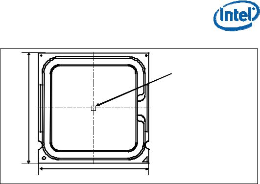
For the processor, the case temperature is defined as the temperature measured at the geometric center of the package on the surface of the IHS. For illustration, Figure 2-2 shows the measurement location for a 37.5 mm x 37.5 mm [1.474 in x 1.474 in] 775-Land LGA processor package with a 28.7 mm x 28.7 mm [1.13 in x 1.13 in] IHS top surface. Techniques for measuring the case temperature are detailed in Section 3.4.
16 |
Thermal and Mechanical Design Guidelines |
Processor Thermal/Mechanical Information
Figure 2-2. Processor Case Temperature Measurement Location
37.5 mm |
37.5 mm |
Measure TC at thispoint (geometric center of thepackage)
2.2.2Thermal Profile
The Thermal Profile defines the maximum case temperature as a function of processor power dissipation. Refer to the datasheet for the further information.
2.2.3Thermal Solution Design Requirements
While the thermal profile provides flexibility for ATX /BTX thermal design based on its intended target thermal environment, thermal solutions that are intended to function in a multitude of systems and environments need to be designed for the worst-case thermal environment. The majority of ATX /BTX platforms are targeted to function in an environment that will have up to a 35° C ambient temperature external to the system.
For ATX platforms, an active air-cooled design, assumed be used in ATX Chassis, with a fan installed at the top of the heatsink equivalent to the reference design (see Chapter 6) should be designed to manage the processor TDP at an inlet temperature of 35° C + 5°C = 40° C.
For BTX platforms, a front-to-back cooling design equivalent to Intel BTX TMA Type II reference design (see the Chapter 5) should be designed to manage the processor TDP at an inlet temperature of 35° C + 0.5° C = 35.5° C.
The slope of the thermal profile was established assuming a generational improvement in thermal solution performance of the Intel reference design. For an example of Intel Core™2 Duo Processor E8000 series with 6 MB in ATX platform, its improvement is about 15% over the Intel reference design (E18764-001). This performance is expressed as the slope on the thermal profile and can be thought of as the thermal resistance of the heatsink attached to the processor, ΨCA (Refer to Section 3.1). The
intercept on the thermal profile assumes a maximum ambient operating condition that is consistent with the available chassis solutions.
Thermal and Mechanical Design Guidelines |
17 |
Processor Thermal/Mechanical Information
The thermal profiles for the Intel Core™2 Duo processor E8000 series with 6 MB cache, Intel Core™2 Duo processor E7000 series with 3 MB cache, and Intel Pentium dual-core processor E6000 and E5000 series with 2 MB cache, and Intel Celeron processor E3000 series with 1 MB cache are defined such that there is a single thermal solution for all of the 775_VR_CONFIG_06 processors.
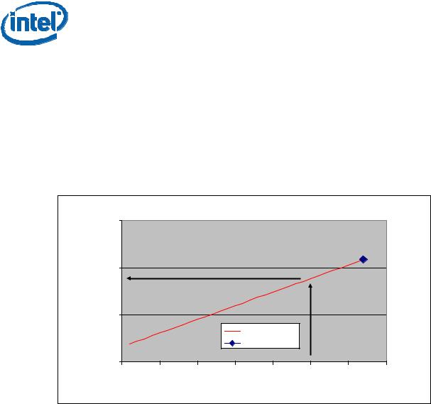
To determine compliance to the thermal profile, a measurement of the actual processor power dissipation is required. The measured power is plotted on the Thermal Profile to determine the maximum case temperature. Using the example in Figure 2-3 for a processor dissipating 50 W the maximum case temperature is 58° C. See the datasheet for the thermal profile.
Figure 2-3. Example Thermal Profile
|
70 |
|
|
|
|
|
|
|
(°C) |
|
|
|
|
|
|
|
|
Temperature |
60 |
|
|
|
|
|
|
|
50 |
|
|
|
|
|
|
|
|
Case |
|
|
|
|
|
|
|
|
|
|
|
|
Thermal Profile |
|
|
|
|
|
|
|
|
|
TDP |
|
|
|
|
40 |
|
|
|
|
|
|
|
|
0 |
10 |
20 |
30 |
40 |
50 |
60 |
70 |
Power (W)
2.2.4TCONTROL
TCONTROL defines the maximum operating temperature for the digital thermal sensor when the thermal solution fan speed is being controlled by the digital thermal sensor.
The TCONTROL parameter defines a very specific processor operating region where fan speed can be reduced. This allows the system integrator a method to reduce the
acoustic noise of the processor cooling solution, while maintaining compliance to the processor thermal specification.
Note: The TCONTROL value for the processor is relative to the Thermal Control Circuit (TCC) activation set point which will be seen as 0 using the digital thermal sensor. As a
result the TCONTROL value will always be a negative number. See Chapter 4 for the discussion the thermal management logic and features and Chapter 7 on Intel Quiet
System Technology (Intel QST).
The value of TCONTROL is driven by a number of factors. One of the most significant of these is the processor idle power. As a result a processor with a high (closer to 0)
TCONTROL will dissipate more power than a part with lower value (farther from 0, such as larger negative number) of TCONTROL when running the same application.
18 |
Thermal and Mechanical Design Guidelines |

Processor Thermal/Mechanical Information
This is achieved in part by using the ΨCA versus RPM and RPM versus Acoustics (dBA)
performance curves from the Intel enabled thermal solution. A thermal solution designed to meet the thermal profile would be expected to provide similar acoustic performance of different parts with potentially different TCONTROL values.
The value for TCONTROL is calculated by the system BIOS based on values read from a factory configured processor register. The result can be used to program a fan speed
control component. See the appropriate processor datasheet for further details on reading the register and calculating TCONTROL.
See Chapter 7, Intel® Quiet System Technology (Intel® QST), for details on implementing a design using TCONTROL and the Thermal Profile.
2.3Heatsink Design Considerations
To remove the heat from the processor, three basic parameters should be considered:
•The area of the surface on which the heat transfer takes place. Without any enhancements, this is the surface of the processor package IHS. One method used to improve thermal performance is by attaching a heatsink to the IHS. A heatsink can increase the effective heat transfer surface area by conducting heat out of the IHS and into the surrounding air through fins attached to the heatsink base.
•The conduction path from the heat source to the heatsink fins. Providing a direct conduction path from the heat source to the heatsink fins and selecting materials with higher thermal conductivity typically improves heatsink performance. The length, thickness, and conductivity of the conduction path from the heat source to the fins directly impact the thermal performance of the heatsink. In particular, the quality of the contact between the package IHS and the heatsink base has a higher impact on the overall thermal solution performance as processor cooling requirements become stricter. Thermal interface material (TIM) is used to fill in the gap between the IHS and the bottom surface of the heatsink, and thereby improve the overall performance of the stack-up (IHS-TIM- Heatsink). With extremely poor heatsink interface flatness or roughness, TIM may not adequately fill the gap. The TIM thermal performance depends on its thermal conductivity as well as the pressure applied to it. Refer to Section 2.3.4 and Appendix C for further information on TIM and on bond line management between the IHS and the heatsink base.
•The heat transfer conditions on the surface on which heat transfer takes place. Convective heat transfer occurs between the airflow and the surface exposed to the flow. It is characterized by the local ambient temperature of the
air, TA, and the local air velocity over the surface. The higher the air velocity over the surface, and the cooler the air, the more efficient is the resulting cooling . The nature of the airflow can also enhance heat transfer using convection. Turbulent flow can provide improvement over laminar flow. In the case of a heatsink, the surface exposed to the flow includes in particular the fin faces and the heatsink base.
Active heatsinks typically incorporate a fan that helps manage the airflow through the heatsink.
Passive heatsink solutions require in-depth knowledge of the airflow in the chassis. Typically, passive heatsinks see lower air speed. These heatsinks are therefore typically larger (and heavier) than active heatsinks due to the increase in fin surface
Thermal and Mechanical Design Guidelines |
19 |

Processor Thermal/Mechanical Information
required to meet a required performance. As the heatsink fin density (the number of fins in a given cross-section) increases, the resistance to the airflow increases: it is more likely that the air travels around the heatsink instead of through it, unless air bypass is carefully managed. Using air-ducting techniques to manage bypass area can be an effective method for controlling airflow through the heatsink.
2.3.1Heatsink Size
The size of the heatsink is dictated by height restrictions for installation in a system and by the real estate available on the motherboard and other considerations for component height and placement in the area potentially impacted by the processor heatsink. The height of the heatsink must comply with the requirements and recommendations published for the motherboard form factor of interest. Designing a heatsink to the recommendations may preclude using it in system adhering strictly to the form factor requirements, while still in compliance with the form factor documentation.
For the ATX/microATX form factor, it is recommended to use:
•The ATX motherboard keep-out footprint definition and height restrictions for enabling components, defined for the platforms designed with the LGA775 socket in Appendix G of this design guide.
•The motherboard primary side height constraints defined in the ATX Specification V2.1 and the microATX Motherboard Interface Specification V1.1 found at http://www.formfactors.org/.
The resulting space available above the motherboard is generally not entirely available for the heatsink. The target height of the heatsink must take into account airflow considerations (for fan performance for example) as well as other design considerations (air duct, and so forth).
For BTX form factor, it is recommended to use:
•The BTX motherboard keep-out footprint definitions and height restrictions for enabling components for platforms designed with the LGA77 socket in Appendix G of this design guide.
•An overview of other BTX system considerations for thermal solutions can be obtained in the latest version of the Balanced Technology Extended (BTX) System Design Guide found at http://www.formfactors.org/.
2.3.2Heatsink Mass
With the need to push air cooling to better performance, heatsink solutions tend to grow larger (increase in fin surface) resulting in increased mass. The insertion of highly thermally conductive materials like copper to increase heatsink thermal conduction performance results in even heavier solutions. As mentioned in
Section 2.1, the heatsink mass must take into consideration the package and socket load limits, the heatsink attach mechanical capabilities, and the mechanical shock and vibration profile targets. Beyond a certain heatsink mass, the cost of developing and implementing a heatsink attach mechanism that can ensure the system integrity under the mechanical shock and vibration profile targets may become prohibitive.
20 |
Thermal and Mechanical Design Guidelines |
Processor Thermal/Mechanical Information
The recommended maximum heatsink mass for the ATX thermal solution is 550g. This mass includes the fan and the heatsink only. The attach mechanism (clip, fasteners, and so forth) are not included.
The mass limit for BTX heatsinks that use Intel reference design structural ingredients is 900 grams. The BTX structural reference component strategy and design is reviewed in depth in the latest version of the Balanced Technology Extended (BTX) System Design Guide.
Note: The 550g mass limit for ATX solutions is based on the capabilities of the reference design components that retain the heatsink to the board and apply the necessary preload. Any reuse of the clip and fastener in derivative designs should not exceed 550g. ATX Designs that have a mass of greater than 550g should analyze the preload as discussed in Appendix A and retention limits of the fastener.
Note: The chipset components on the board are affected by processor heatsink mass. Exceeding these limits may require the evaluation of the chipset for shock and vibration.
2.3.3Package IHS Flatness
The package IHS flatness for the product is specified in the datasheet and can be used as a baseline to predict heatsink performance during the design phase.
Intel recommends testing and validating heatsink performance in full mechanical enabling configuration to capture any impact of IHS flatness change due to combined socket and heatsink loading. While socket loading alone may increase the IHS warpage, the heatsink preload redistributes the load on the package and improves the resulting IHS flatness in the enabled state.
2.3.4Thermal Interface Material
Thermal interface material application between the processor IHS and the heatsink base is generally required to improve thermal conduction from the IHS to the heatsink. Many thermal interface materials can be pre-applied to the heatsink base prior to shipment from the heatsink supplier and allow direct heatsink attach, without the need for a separate thermal interface material dispense or attach process in the final assembly factory.
All thermal interface materials should be sized and positioned on the heatsink base in a way that ensures the entire processor IHS area is covered. It is important to compensate for heatsink-to-processor attach positional alignment when selecting the proper thermal interface material size.
When pre-applied material is used, it is recommended to have a protective application tape over it. This tape must be removed prior to heatsink installation.
Thermal and Mechanical Design Guidelines |
21 |

Processor Thermal/Mechanical Information
2.4System Thermal Solution Considerations
2.4.1Chassis Thermal Design Capabilities
The Intel reference thermal solutions and Intel Boxed Processor thermal solutions assume that the chassis delivers a maximum TA at the inlet of the processor fan heatsink. The following tables show the TA requirements for the reference solutions and Intel Boxed Processor thermal solutions.
Table 2–1. Heatsink Inlet Temperature of Intel Reference Thermal Solutions
Topic |
ATX E18764-0011 |
BTX Type II |
Heatsink Inlet Temperature |
40° C |
35.5° C |
|
|
|
NOTE:
1.Intel reference designs (E18764-001) for ATX assume the use of the thermally advantaged chassis (refer to Thermally Advantaged Chassis (TAC) Design Guide for TAC thermal and mechanical requirements). The TAC 2.0 Design Guide defines a new processor cooling solution inlet temperature target of 40° C. The existing TAC 1.1 chassis can be compatible with TAC 2.0 guidelines.
Table 2–2. Heatsink Inlet Temperature of Intel Boxed Processor Thermal Solutions
Topic |
Boxed Processor for Intel® Core™2 Duo Processor |
|
E8000, E7000 Series, Intel® Pentium® Dual-Core |
|
Processor E6000, E5000 Series, and Intel® |
|
Celeron® Processor E3000 Series |
|
|
Heatsink Inlet Temperature |
40° C |
|
|
NOTE:
1.Boxed Processor thermal solutions for ATX assume the use of the thermally advantaged chassis (refer to Thermally Advantaged Chassis (TAC) Design Guide for TAC thermal and mechanical requirements). The TAC 2.0 Design Guide defines a new processor cooling solution inlet temperature target of 40° C. The existing TAC 1.1 chassis can be compatible with TAC 2.0 guidelines.
2.4.2Improving Chassis Thermal Performance
The heat generated by components within the chassis must be removed to provide an adequate operating environment for both the processor and other system components. Moving air through the chassis brings in air from the external ambient environment and transports the heat generated by the processor and other system components out of the system. The number, size and relative position of fans and vents determine the chassis thermal performance, and the resulting ambient temperature around the processor. The size and type (passive or active) of the thermal solution and the amount of system airflow can be traded off against each other to meet specific system design constraints. Additional constraints are board layout, spacing, component placement, acoustic requirements, and structural considerations that limit the thermal solution size. For more information, refer to the
Performance ATX Desktop System Thermal Design Suggestions or Performance microATX Desktop System Thermal Design Suggestions or Balanced Technology Extended (BTX) System Design Guide documents available on the http://www.formfactors.org/ web site.
22 |
Thermal and Mechanical Design Guidelines |

Processor Thermal/Mechanical Information
In addition to passive heatsinks, fan heatsinks and system fans are other solutions that exist for cooling integrated circuit devices. For example, ducted blowers, heat pipes, and liquid cooling are all capable of dissipating additional heat. Due to their varying attributes, each of these solutions may be appropriate for a particular system implementation.
To develop a reliable, cost-effective thermal solution, thermal characterization and simulation should be carried out at the entire system level, accounting for the thermal requirements of each component. In addition, acoustic noise constraints may limit the size, number, placement, and types of fans that can be used in a particular design.
To ease the burden on thermal solutions, the Thermal Monitor feature and associated logic have been integrated into the silicon of the processor. By taking advantage of the Thermal Monitor feature, system designers may reduce thermal solution cost by designing to TDP instead of maximum power. Thermal Monitor attempts to protect the processor during sustained workload above TDP. Implementation options and recommendations are described in Chapter 4.
2.4.3Summary
In summary, considerations in heatsink design include:
•The local ambient temperature TA at the heatsink, which is a function of chassis design.
•The thermal design power (TDP) of the processor, and the corresponding
maximum TC as calculated from the thermal profile. These parameters are usually combined in a single lump cooling performance parameter, ΨCA (case to air thermal characterization parameter). More information on the definition and the use of ΨCA is given Section 3.1.
•Heatsink interface to IHS surface characteristics, including flatness and roughness.
•The performance of the thermal interface material used between the heatsink and the IHS.
•The required heatsink clip static load, between 18 lbf to 70 lbf throughout the life of the product (Refer to Section 2.1.2.2 for further information).
•Surface area of the heatsink.
•Heatsink material and technology.
•Volume of airflow over the heatsink surface area.
•Development of airflow entering and within the heatsink area.
•Physical volumetric constraints placed by the system
2.5System Integration Considerations
Manufacturing with Intel® Components using 775–Land LGA Package and LGA775 Socket documentation provides Best Known Methods for all aspects LGA775 socket based platforms and systems manufacturing. Of particular interest for package and heatsink installation and removal is the System Assembly module. A video covering system integration is also available. Contact your Intel field sales representative for further information.
§
Thermal and Mechanical Design Guidelines |
23 |

Processor Thermal/Mechanical Information
24 |
Thermal and Mechanical Design Guidelines |

Thermal Metrology
3 Thermal Metrology
This section discusses guidelines for testing thermal solutions, including measuring processor temperatures. In all cases, the thermal engineer must measure power dissipation and temperature to validate a thermal solution. To define the performance of a thermal solution the “thermal characterization parameter”, Ψ (“psi”) will be used.
3.1Characterizing Cooling Performance Requirements
The idea of a “thermal characterization parameter”, Ψ (“psi”), is a convenient way to characterize the performance needed for the thermal solution and to compare thermal solutions in identical situations (same heat source and local ambient conditions). The thermal characterization parameter is calculated using total package power.
Note: Heat transfer is a three-dimensional phenomenon that can rarely be accurately and easily modeled by a single resistance parameter like Ψ.
The case-to-local ambient thermal characterization parameter value (ΨCA) is used as a measure of the thermal performance of the overall thermal solution that is attached to the processor package. It is defined by the following equation, and measured in units of °C/W:
ΨCA = (TC – TA) / PD (Equation 1)
Where: |
|
ΨCA |
= Case-to-local ambient thermal characterization parameter (°C/W) |
TC |
= Processor case temperature (°C) |
TA |
= Local ambient temperature in chassis at processor (°C) |
PD |
= Processor total power dissipation (W) (assumes all power dissipates |
|
through the IHS) |
The case-to-local ambient thermal characterization parameter of the processor, ΨCA, is comprised of ΨCS, the thermal interface material thermal characterization parameter, and of ΨSA, the sink-to-local ambient thermal characterization parameter:
ΨCA = ΨCS + ΨSA (Equation 2)
Where:
ΨCS = Thermal characterization parameter of the thermal interface material (°C/W)
ΨSA = Thermal characterization parameter from heatsink-to-local ambient (°C/W)
ΨCS is strongly dependent on the thermal conductivity and thickness of the TIM between the heatsink and IHS.
Thermal and Mechanical Design Guidelines |
25 |
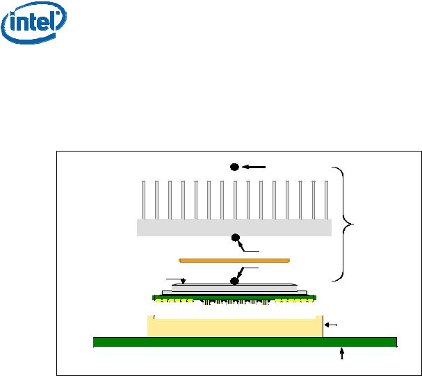
Thermal Metrology
ΨSA is a measure of the thermal characterization parameter from the bottom of the heatsink to the local ambient air. ΨSA is dependent on the heatsink material, thermal conductivity, and geometry. It is also strongly dependent on the air velocity through the fins of the heatsink.
Figure 3-1 illustrates the combination of the different thermal characterization parameters.
Figure 3-1. Processor Thermal Characterization Parameter Relationships
|
TA |
|
Heatsink |
ΨCA |
|
TIM |
TS |
|
TC |
||
IHS |
||
Processor |
|
|
|
LGA775 Socket |
|
|
System Board |
3.1.1Example
The cooling performance, ΨCA, is defined using the principle of thermal characterization parameter described above:
•The case temperature TC-MAX and thermal design power TDP given in the processor datasheet.
•Define a target local ambient temperature at the processor, TA.
Since the processor thermal profile applies to all processor frequencies, it is important to identify the worst case (lowest ΨCA) for a targeted chassis characterized by TA to establish a design strategy.
The following provides an illustration of how one might determine the appropriate performance targets. The example power and temperature numbers used here are not related to any specific Intel processor thermal specifications, and are for illustrative purposes only.
26 |
Thermal and Mechanical Design Guidelines |

Thermal Metrology
Assume the TDP, as listed in the datasheet, is 100 W and the maximum case temperature from the thermal profile for 100 W is 67° C. Assume as well that the system airflow has been designed such that the local ambient temperature is 38° C. Then, the following could be calculated using equation 1 from above:
ΨCA = (TC, − TA) / TDP = (67 – 38) / 100 = 0.29° C/W
To determine the required heatsink performance, a heatsink solution provider would need to determine ΨCS performance for the selected TIM and mechanical load configuration. If the heatsink solution were designed to work with a TIM material performing at ΨCS ≤ 0.10° C/W, solving for equation 2 from above, the performance of the heatsink would be:
ΨSA = ΨCA − ΨCS = 0.29 − 0.10 = 0.19° C/W
3.2Processor Thermal Solution Performance Assessment
Thermal performance of a heatsink should be assessed using a thermal test vehicle (TTV) provided by Intel. The TTV is a stable heat source that the user can make accurate power measurement, whereas processors can introduce additional factors that can impact test results. In particular, the power level from actual processors varies significantly, even when running the maximum power application provided by Intel, due to variances in the manufacturing process. The TTV provides consistent power and power density for thermal solution characterization and results can be easily translated to real processor performance. Accurate measurement of the power dissipated by an actual processor is beyond the scope of this document.
Once the thermal solution is designed and validated with the TTV, it is strongly recommended to verify functionality of the thermal solution on real processors and on fully integrated systems. The Intel maximum power application enables steady power dissipation on a processor to assist in this testing. This maximum power application is provided by Intel.
3.3Local Ambient Temperature Measurement Guidelines
The local ambient temperature TA is the temperature of the ambient air surrounding the processor. For a passive heatsink, TA is defined as the heatsink approach air temperature; for an actively cooled heatsink, it is the temperature of inlet air to the active cooling fan.
It is worthwhile to determine the local ambient temperature in the chassis around the processor to understand the effect it may have on the case temperature.
TA is best measured by averaging temperature measurements at multiple locations in the heatsink inlet airflow. This method helps reduce error and eliminate minor spatial variations in temperature. The following guidelines are meant to enable accurate determination of the localized air temperature around the processor during system thermal testing.
Thermal and Mechanical Design Guidelines |
27 |

Thermal Metrology
For active heatsinks, it is important to avoid taking measurement in the dead flow zone that usually develops above the fan hub and hub spokes. Measurements should be taken at four different locations uniformly placed at the center of the annulus formed by the fan hub and the fan housing to evaluate the uniformity of the air temperature at the fan inlet. The thermocouples should be placed approximately
3 mm to 8 mm [0.1 to 0.3 in] above the fan hub vertically and halfway between the fan hub and the fan housing horizontally as shown in the ATX heatsink in Figure 3-2 (avoiding the hub spokes). Using an open bench to characterize an active heatsink can be useful, and usually ensures more uniform temperatures at the fan inlet. However, additional tests that include a solid barrier above the test motherboard surface can help evaluate the potential impact of the chassis. This barrier is typically clear Plexiglas*, extending at least 100 mm [4 in] in all directions beyond the edge of the thermal solution. Typical distance from the motherboard to the barrier is 81 mm
[3.2 in]. For even more realistic airflow, the motherboard should be populated with significant elements like memory cards, graphic card, and chipset heatsink. If a barrier is used, the thermocouple can be taped directly to the barrier with a clear tape at the horizontal location as previously described, half way between the fan hub and the fan housing. If a variable speed fan is used, it may be useful to add a thermocouple taped to the barrier above the location of the temperature sensor used by the fan to check its speed setting against air temperature. When measuring TA in a chassis with a live motherboard, add-in cards, and other system components, it is likely that the TA measurements will reveal a highly non-uniform temperature distribution across the inlet fan section.
For passive heatsinks, thermocouples should be placed approximately 13 mm to 25 mm [0.5 to 1.0 in] away from processor and heatsink as shown in Figure 3-3. The thermocouples should be placed approximately 51 mm [2.0 in] above the baseboard. This placement guideline is meant to minimize the effect of localized hot spots from baseboard components.
Note: Testing an active heatsink with a variable speed fan can be done in a thermal chamber to capture the worst-case thermal environment scenarios. Otherwise, when doing a bench top test at room temperature, the fan regulation prevents the heatsink from operating at its maximum capability. To characterize the heatsink capability in the worst-case environment in these conditions, it is then necessary to disable the fan regulation and power the fan directly, based on guidance from the fan supplier.
28 |
Thermal and Mechanical Design Guidelines |

Thermal Metrology
Figure 3-2. Locations for Measuring Local Ambient Temperature, Active ATX Heatsink
Note: Drawing Not to Scale
Figure 3-3. Locations for Measuring Local Ambient Temperature, Passive Heatsink
Note: Drawing Not to Scale
Thermal and Mechanical Design Guidelines |
29 |

Thermal Metrology
3.4Processor Case Temperature Measurement Guidelines
To ensure functionality and reliability, the processor is specified for proper operation when TC is maintained at or below the thermal profile as listed in the datasheet. The measurement location for TC is the geometric center of the IHS. Figure 2-2 shows the location for TC measurement.
Special care is required when measuring TC to ensure an accurate temperature measurement. Thermocouples are often used to measure TC. Before any temperature measurements are made, the thermocouples must be calibrated, and the complete measurement system must be routinely checked against known standards. When measuring the temperature of a surface that is at a different temperature from the surrounding local ambient air, errors could be introduced in the measurements. The measurement errors could be caused by poor thermal contact between the junction of the thermocouple and the surface of the integrated heat spreader, heat loss by radiation, convection, by conduction through thermocouple leads, or by contact between the thermocouple cement and the heatsink base.
Appendix D defines a reference procedure for attaching a thermocouple to the IHS of a 775-Land LGA processor package for TC measurement. This procedure takes into account the specific features of the 775-Land LGA package and of the LGA775 socket for which it is intended.
§
30 |
Thermal and Mechanical Design Guidelines |
Loading...