


 Loading...
AV Receiver
DTR-20.2
Instruction Manual
WARNING:
TO REDUCE THE RISK OF FIRE OR ELECTRIC SHOCK, DO NOT EXPOSE THIS APPARATUS TO RAIN OR MOISTURE.
CAUTION:
TO REDUCE THE RISK OF ELECTRIC SHOCK, DO NOT REMOVE COVER (OR BACK). NO USER-SERVICEABLE PARTS INSIDE. REFER SERVICING TO QUALIFIED SERVICE PERSONNEL.
WARNING |
|
AVIS |
RISK OF ELECTRIC SHOCK |
|
RISQUE DE CHOC ELECTRIQUE |
DO NOT OPEN |
|
NE PAS OUVRIR |
The lightning flash with arrowhead symbol, within an equilateral triangle, is intended to alert the user to the presence of uninsulated “dangerous voltage” within the product’s enclosure that may be of sufficient
magnitude to constitute a risk of electric shock to persons.
The exclamation point within an equilateral triangle is intended to alert the user to the presence of important operating and maintenance (servicing) instructions in the literature accompanying the appliance.
Important Safety Instructions
1.Read these instructions.
2.Keep these instructions.
3.Heed all warnings.
4.Follow all instructions.
5.Do not use this apparatus near water.
6.Clean only with dry cloth.
7.Do not block any ventilation openings. Install in accordance with the manufacturer’s instructions.
8.Do not install near any heat sources such as radiators, heat registers, stoves, or other apparatus (including amplifiers) that produce heat.
9.Do not defeat the safety purpose of the polarized or grounding-type plug. A polarized plug has two blades with one wider than the other. A grounding type plug has two blades and a third grounding prong. The wide blade or the third prong are provided for your safety. If the provided plug does not fit into your outlet, consult an electrician for replacement of the obsolete outlet.
10.Protect the power cord from being walked on or pinched particularly at plugs, convenience receptacles, and the point where they exit from the apparatus.
11.Only use attachments/accessories specified by the
manufacturer.
12. Use only with the cart, stand, tripod, bracket, or table speci-
fied by the manufacturer, or sold with the apparatus. When
a cart is used, use caution when moving the cart/appara-
tus combination to avoid
S3125A
injury from tip-over.
13.Unplug this apparatus during lightning storms or when unused for long periods of time.
14.Refer all servicing to qualified service personnel. Servicing is required when the apparatus has been damaged in any way, such as power-supply cord or plug is damaged, liquid has been spilled or objects have fallen into the apparatus, the apparatus has been exposed to rain or moisture, does not operate normally, or has been dropped.
15.Damage Requiring Service
Unplug the apparatus from the wall outlet and refer servicing to qualified service personnel under the following conditions:
A.When the power-supply cord or plug is damaged,
B.If liquid has been spilled, or objects have fallen into the apparatus,
C.If the apparatus has been exposed to rain or water,
D.If the apparatus does not operate normally by following the operating instructions. Adjust only those controls that are covered by the operating instructions as an improper adjustment of other controls may result in damage and will often require extensive work by a qualified technician to restore the apparatus to its normal operation,
E.If the apparatus has been dropped or damaged in any way, and
F.When the apparatus exhibits a distinct change in performance this indicates a need for service.
16.Object and Liquid Entry
Never push objects of any kind into the apparatus through openings as they may touch dangerous voltage points or short-out parts that could result in a fire or electric shock.
The apparatus shall not be exposed to dripping or splashing and no objects filled with liquids, such as vases shall be placed on the apparatus.
Don’t put candles or other burning objects on top of this unit.
17.Batteries
Always consider the environmental issues and follow local regulations when disposing of batteries.
18.If you install the apparatus in a built-in installation, such as a bookcase or rack, ensure that there is adequate ventilation.
Leave 20 cm (8") of free space at the top and sides and 10 cm (4") at the rear. The rear edge of the shelf or board above the apparatus shall be set 10 cm (4") away from the rear panel or wall, creating a flue-like gap for warm air to escape.
En
2

Precautions
1.Recording Copyright—Unless it’s for personal use only, recording copyrighted material is illegal without the permission of the copyright holder.
2.AC Fuse—The AC fuse inside the unit is not user-ser- viceable. If you cannot turn on the unit, contact the dealer from whom you purchased this unit.
3.Care—Occasionally you should dust the unit all over with a soft cloth. For stubborn stains, use a soft cloth dampened with a weak solution of mild detergent and water. Dry the unit immediately afterwards with a clean cloth. Don’t use abrasive cloths, thinners, alcohol, or other chemical solvents, because they may damage the finish or remove the panel lettering.
4.Power WARNING
BEFORE PLUGGING IN THE UNIT FOR THE FIRST TIME, READ THE FOLLOWING SECTION CAREFULLY.
AC outlet voltages vary from country to country. Make sure that the voltage in your area meets the voltage requirements printed on the unit’s rear panel (e.g., AC 230 V, 50 Hz or AC 120 V, 60 Hz).
The power cord plug is used to disconnect this unit from the AC power source. Make sure that the plug is readily operable (easily accessible) at all times.
Pressing On/Standby to select Standby mode does not fully shutdown the unit. If you do not intend to use the unit for an extended period, remove the power cord from the AC outlet.
5.Preventing Hearing Loss Caution
Excessive sound pressure from earphones and headphones can cause hearing loss.
6.Batteries and Heat Exposure Warning
Batteries (battery pack or batteries installed) shall not be exposed to excessive heat as sunshine, fire or the like.
7.Never Touch this Unit with Wet Hands—Never handle this unit or its power cord while your hands are wet or damp. If water or any other liquid gets inside this unit, have it checked by the dealer from whom you purchased this unit.
8.Handling Notes
For U.S. models
FCC Information for User CAUTION:
The user changes or modifications not expressly approved by the party responsible for compliance could void the user’s authority to operate the equipment.
NOTE:
This equipment has been tested and found to comply with the limits for a Class B digital device, pursuant to Part 15 of the FCC Rules. These limits are designed to provide reasonable protection against harmful interference in a residential installation.
This equipment generates, uses and can radiate radio frequency energy and, if not installed and used in accordance with the instructions, may cause harmful interference to radio communications. However, there is no guarantee that interference will not occur in a particular installation. If this equipment does cause harmful interference to radio or television reception, which can be determined by turning the equipment off and on, the user is encouraged to try to correct the interference by one or more of the following measures:
•Reorient or relocate the receiving antenna.
•Increase the separation between the equipment and receiver.
•Connect the equipment into an outlet on a circuit different from that to which the receiver is connected.
•Consult the dealer from whom you purchased this unit or an experienced radio/TV technician for help.
•If you need to transport this unit, use the original packaging to pack it how it was when you originally bought it.
•Do not leave rubber or plastic items on this unit for a long time, because they may leave marks on the case.
•This unit’s top and rear panels may get warm after prolonged use. This is normal.
•If you do not use this unit for a long time, it may not work properly the next time you turn it on, so be sure to use it occasionally.
En
3
Thank you for purchasing an Integra AV receiver. Please read this manual thoroughly before making connections and plugging in the unit.
Following the instructions in this manual will enable you to obtain optimum performance and listening enjoyment from your new AV receiver.
Please retain this manual for future reference.
Supplied Accessories
Make sure you have the following accessories:
Indoor FM antenna ( 18)
AM loop antenna ( 18)
Power cord ( 18)
(Plug type varies from country to country.)
Speaker cable labels ( 11)
Speaker setup microphone ( 24)
Remote controller and two batteries (AA/R6)
*In catalogs and on packaging, the letter at the end of the product name indicates the color. Specifications and operations are the same regardless of color.
Using the Remote Controller
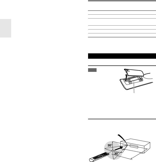
Installing the Batteries
Note
• If the remote controller
doesn’t work reliably, try replacing the batteries.
• Don’t mix new and old batteries or different
types of batteries.
• If you intend not to use the remote controller for
a long time, remove the batteries to prevent damage from leakage or corrosion.
• Remove expired batteries as soon as possible to prevent damage from leakage or corrosion.
Aiming the Remote Controller
To use the remote controller, point it at the AV receiver’s remote control sensor, as shown below.
Remote control sensor
AV receiver
Approx. 16 ft. (5 m)
En
4

Contents
Introduction |
|
Important Safety Instructions ......................................... |
2 |
Precautions....................................................................... |
3 |
Supplied Accessories...................................................... |
4 |
Using the Remote Controller .......................................... |
4 |
Features ............................................................................ |
6 |
Front & Rear Panels......................................................... |
7 |
Front Panel..................................................................... |
7 |
Display............................................................................ |
8 |
Rear Panel ..................................................................... |
8 |
Remote Controller............................................................ |
9 |
Controlling the AV Receiver ........................................... |
9 |
About Home Theater...................................................... |
10 |
Enjoying Home Theater................................................ |
10 |
Connections |
|
Connecting the AV Receiver ......................................... |
11 |
Connecting Your Speakers .......................................... |
11 |
About AV Connections ................................................. |
14 |
Connecting Components with HDMI ............................ |
15 |
Connecting External Components................................ |
16 |
Connecting Integra/Onkyo uComponents ................ |
17 |
Connecting Antenna..................................................... |
18 |
Connecting the Power Cord ......................................... |
18 |
Which Connections Should I Use?............................... |
19 |
Turning On & Basic Operations |
|
Turning On/Off the AV Receiver ................................... |
20 |
Turning On ................................................................... |
20 |
Turning Off ................................................................... |
20 |
Basic Operations............................................................ |
21 |
Selecting the Language Used for the Onscreen |
|
Setup Menus.............................................................. |
21 |
Playing the Connected Component.............................. |
21 |
Displaying Source Information ..................................... |
21 |
Setting the Display Brightness ..................................... |
21 |
Muting the AV Receiver................................................ |
22 |
Using the Sleep Timer.................................................. |
22 |
Using the Home Menu.................................................. |
22 |
Changing the Input Display .......................................... |
23 |
Using Headphones....................................................... |
23 |
Audyssey 2EQ® Room Correction and |
|
Speaker Setup ........................................................... |
23 |
Listening to the Radio ................................................... |
26 |
Using the Tuner............................................................ |
26 |
Presetting FM/AM Stations........................................... |
27 |
Recording ....................................................................... |
28 |
Using the Listening Modes ........................................... |
29 |
Selecting Listening Modes ........................................... |
29 |
About Listening Modes................................................. |
30 |
Advanced Operations |
|
Advanced Setup ............................................................. |
35 |
On-screen Setup Menus............................................... |
35 |
Common Procedures in Setup Menu ........................... |
35 |
Input/Output Assign ...................................................... |
36 |
Speaker Setup.............................................................. |
37 |
Audio Adjust ................................................................. |
40 |
Source Setup................................................................ |
41 |
Listening Mode Preset.................................................. |
45 |
Miscellaneous............................................................... |
46 |
Hardware Setup............................................................ |
46 |
Lock Setup.................................................................... |
48 |
Using the Audio Settings .............................................. |
48 |
Adjusting the Bass & Treble ......................................... |
50 |
Zone 2.............................................................................. |
51 |
Connecting Zone 2 ....................................................... |
51 |
Setting the Zone2 Out .................................................. |
51 |
Using Zone 2 ................................................................ |
52 |
Using the 12V Triggers................................................. |
53 |
Using the Remote Controller in Zone 2 and |
|
Multiroom Control Kits................................................ |
54 |
Controlling iPod & Other Components |
|
Controlling iPod ............................................................. |
55 |
Connecting an Onkyo Dock.......................................... |
55 |
Using the Onkyo Dock.................................................. |
56 |
Controlling Your iPod.................................................... |
57 |
Controlling Other Components..................................... |
59 |
Preprogrammed Remote Control Codes ...................... |
59 |
Looking up for Remote Control Code ........................... |
59 |
Entering Remote Control Codes................................... |
60 |
Remote Control Codes for Integra/Onkyo |
|
Components Connected via u................................ |
60 |
Resetting Remote Mode Buttons.................................. |
61 |
Resetting the Remote Controller .................................. |
61 |
Controlling Other Components ..................................... |
61 |
Others |
|
Troubleshooting ............................................................. |
63 |
Specifications ................................................................. |
67 |
About HDMI..................................................................... |
68 |
Using an RIHD-compatible TV, Player, or Recorder ... |
69 |
Video Resolution Chart.................................................. |
71 |
To reset the AV receiver to its factory defaults, turn it on and, while holding down VCR/DVR, press
On/Standby ( 63).
En
5

Features
Amplifier
•105 Watts/Channel @ 8 ohms (FTC)
•WRAT–Wide Range Amplifier Technology (5 Hz to 100 kHz bandwidth)
•Optimum Gain Volume Circuitry
•H.C.P.S. (High Current Power Supply) Massive High Power Transformer
•Jitter Cleaning Circuit Technology
Processing
•THX Select2 Plus*1 Certified
•HDMI Video Upscaling (to 1080p Compatible) with Faroudja DCDi Cinema Enhancement
•HDMI (Ver.1.4 with Audio Return Channel, 3D), DeepColor, x.v.Color*, Lip Sync, DTS*2-HD Master Audio, DTS-HD High Resolution Audio, Dolby TrueHD*3, Dolby Digital Plus, DSD and Multi-CH PCM
•Non-Scaling Configuration
•A-Form Listening Mode Memory
•Direct Mode
•Music Optimizer*4 for Compressed Digital Music files
•192 kHz/24-bit D/A Converters
•Powerful and Highly Accurate 32-bit Processing DSP
Connections
•5 HDMI*5 Inputs and 1 Output
•Integra/Onkyo pfor System Control
•4 Digital Inputs (2 Optical/2 Coaxial)
•Component Video Switching (2 Inputs/1 Output)
•Universal Port for the Dock for iPod*/HD Radio™*6 tuner module
•Banana Plug-Compatible Speaker Posts
•Zone 2 Pre Out
•IR Input/Output and 12 V Trigger
•RS232 Port for Interface Control
•Surround Back L/R and Dual Subwoofer Pre Out
•Analog RGB Video Input (D-sub 15) for PC
Miscellaneous
•40 FM/AM Presets
•Audyssey 2EQ®*7 to Correct Room Acoustic Problems
•Audyssey Dynamic EQ®*7 for Loudness Correction
•Audyssey Dynamic Volume™*7 to Maintain Optimal Listening Level and Dynamic Range
•Crossover Adjustment (40/45/50/55/60/70/80/90/100/110/120/130/150/200 Hz)
•A/V Sync Control Function (up to 200 ms)
•On-Screen Display via HDMI
•Preprogrammed u-Compatible Remote
En
*1
THX and the THX logo are trademarks of THX Ltd. which may be registered in some jurisdictions. All rights reserved.
*2
Manufactured under license under U.S. Patent #’s: 5,451,942; 5,956,674; 5,974,380; 5,978,762; 6,226,616; 6,487,535; 7,212,872; 7,333,929; 7,392,195; 7,272,567 & other U.S. and worldwide patents issued & pending. DTS is a registered trademark and the DTS logos, Symbol, DTS-HD and DTSHD Master Audio are trademarks of DTS, Inc.
©1996-2008 DTS, Inc. All Rights Reserved.
*3
Manufactured under license from Dolby Laboratories. “Dolby”, “Pro Logic”, “Surround EX” and the double-D symbol are trademarks of Dolby Laboratories.
*4 Music Optimizer™ is a trademark of Onkyo Corporation.
*5
“HDMI, the HDMI Logo, and High-Definition Multimedia Interface are trademarks or registered trademarks of HDMI Licensing LLC in the United States and other countries.”
*6
HD Radio™ and the HD Radio Ready logo are proprietary trademarks of iBiquity Digital Corporation.
To receive HD Radio broadcasts, you must install an Onkyo UP-HT1 HD Radio tuner module (sold separately).
*7
Manufactured under license from Audyssey Laboratories™. U.S. and foreign patents pending. Audyssey 2EQ®, Audyssey Dynamic Volume™ and Audyssey Dynamic EQ® are trademarks of Audyssey Laboratories.
THX Select2 Plus
Before any home theater component can be THX Select2 Plus certified, it must pass a rigorous series of quality and performance tests. Only then can a product feature the THX Select2 Plus logo, which is your guarantee that the Home Theater products you purchase will give you superb performance for many years to come. THX Select2 Plus requirements define hundreds of parameters, including power amplifier performance, and pre-amplifier performance and operation for both digital and analog domains. THX Select2 Plus receivers also feature proprietary THX technologies (e.g., THX Mode) which accurately translate movie soundtracks for home theater playback.
*“Xantech” is a registered trademark of Xantech Corporation.
*“Niles” is a registered trademark of Niles Audio Corporation.
*Apple and iPod are trademarks of Apple Inc., registered in the U.S. and other countries.
*“x.v.Color” is a trademark of Sony Corporation.
6

Front & Rear Panels
Front Panel
a b c d e fg h i j k l mn o p q
|
|
|
|
|
|
|
|
|
|
|
|
|
|
|
|
|
|
|
|
|
|
|
|
|
|
|
|
|
|
|
|
|
|
|
|
|
|
|
|
|
|
|
|
|
|
|
|
|
|
|
|
|
|
|
|
|
|
|
|
|
|
|
|
|
|
|
|
|
|
|
|
|
|
|
|
|
|
|
|
|
|
|
|
|
|
|
|
|
|
|
|
|
|
|
|
|
|
|
|
|
|
|
|
|
|
|
|
|
|
|
|
|
|
|
|
|
|
|
|
|
|
|
|
|
|
|
|
|
|
|
|
|
|
|
|
|
|
|
|
|
|
|
|
|
|
|
|
|
|
|
|
|
|
|
|
|
|
|
|
|
|
|
|
|
|
|
|
|
|
|
|
|
|
|
|
|
|
|
|
|
|
|
|
|
|
|
|
|
|
|
|
|
|
|
|
|
|
|
|
|
|
|
|
|
|
|
|
|
|
|
|
|
|
|
|
|
|
|
|
|
|
|
|
|
|
|
|
|
|
|
|
|
|
|
|
|
|
|
|
|
|
|
|
|
|
|
|
|
|
|
|
|
|
|
|
|
|
|
|
|
|
|
|
|
|
|
|
|
|
|
|
|
|
|
|
|
|
|
|
|
|
|
|
|
|
|
|
|
|
|
|
|
|
|
|
|
|
|
|
|
|
|
|
|
|
|
|
|
|
|
|
|
|
|
|
|
|
|
|
|
|
|
|
|
|
|
|
|
|
|
|
|
|
|
|
|
|
|
|
|
|
|
|
|
|
|
|
|
|
|
|
|
|
|
|
|
|
|
|
|
|
|
|
|
|
|
|
|
|
|
|
|
|
|
|
|
|
|
|
|
|
|
|
|
|
|
|
|
|
|
|
|
|
|
|
|
|
|
|
|
|
|
|
|
|
|
|
|
|
|
|
|
|
|
|
|
|
|
|
|
|
|
|
|
|
|
|
|
|
|
|
|
|
|
|
|
|
|
|
|
|
|
|
|
|
|
|
|
|
rst |
|
|
|
u |
|
|
|
|
|
|
v |
|
|||||||||||||||||
The actual front panel has various logos printed on it. They are not shown here for clarity.
The page numbers in parentheses show where you can find the main explanation for each item.
a On/Standby button ( 20)
b Standby indicator ( 20)
c Zone 2 indicator ( 52)
d Tone and Tone Level buttons ( 50, 52)
e Remote control sensor ( 4)
f Display ( 8)
g Movie/TV button ( 29)
h Music button ( 29)
i Game button ( 29)
j Dimmer button ( 21)
k Memory button ( 27)
l Tuning Mode button ( 26) m Display button ( 21)
n Setup button ( 35)
oTuning, Preset ( 26 to 27), Arrow, and Enter buttons
p Return button
q Master Volume control ( 21) r Zone 2 and Off buttons ( 52) s Zone 2 Level buttons ( 52) t Phones jack ( 23)
u Input Selector buttons ( 21) v Setup Mic jack ( 24)
En
7

Display
a |
b |
c |
d |
e |
|
|
|
|
f |
|
|
|
|
g |
For detailed information, see the pages in parentheses.
a Audio input indicators |
e SLEEP indicator ( 22) |
b Listening mode and format indicators ( 29, 49) |
f MUTING indicator ( 22) |
c Audyssey indicators ( 23, 41) |
g Message area |
d Tuning indicators ( 26)
Rear Panel
a |
|
|
|
|
|
|
|
|
|
|
|
|
b c d e fg |
|
|
h i jk*l m |
||||||||||||||||||||||||||||||||||||||||||||||||||||||||||||||||
|
|
|
|
|
|
|
|
|
|
|
|
|
|
|
|
|
|
|
|
|
|
|
|
|
|
|
|
|
|
|
|
|
|
|
|
|
|
|
|
|
|
|
|
|
|
|
|
|
|
|
|
|
|
|
|
|
|
|
|
|
|
|
|
|
|
|
|
|
|
|
|
|
|
|
|
|
|
|
|
|
|
|
|
|
|
|
|
|
|
|
|
|
|
|
|
|
|
|
|
|
|
|
|
|
|
|
|
|
|
|
|
|
|
|
|
|
|
|
|
|
|
|
|
|
|
|
|
|
|
|
|
|
|
|
|
|
|
|
|
|
|
|
|
|
|
|
|
|
|
|
|
|
|
|
|
|
|
|
|
|
|
|
|
|
|
|
|
|
|
|
|
|
|
|
|
|
|
|
|
|
|
|
|
|
|
|
|
|
|
|
|
|
|
|
|
|
|
|
|
|
|
|
|
|
|
|
|
|
|
|
|
|
|
|
|
|
|
|
|
|
|
|
|
|
|
|
|
|
|
|
|
|
|
|
|
|
|
|
|
|
|
|
|
|
|
|
|
|
|
|
|
|
|
|
|
|
|
|
|
|
|
|
|
|
|
|
|
|
|
|
|
|
|
|
|
|
|
|
|
|
|
|
|
|
|
|
|
|
|
|
|
|
|
|
|
|
|
|
|
|
|
|
|
|
|
|
|
|
|
|
|
|
|
|
|
|
|
|
|
|
|
|
|
|
|
|
|
|
|
|
|
|
|
|
|
|
|
|
|
|
|
|
|
|
|
|
|
|
|
|
|
|
|
|
|
|
|
|
|
|
|
|
|
|
|
|
|
|
|
|
|
|
|
|
|
|
|
|
|
|
|
|
|
|
|
|
|
|
|
|
|
|
|
|
|
|
|
|
|
|
|
|
|
|
|
|
|
|
|
|
|
|
|
|
|
|
|
|
|
|
|
|
|
|
|
|
|
|
|
|
|
|
|
|
|
|
|
|
|
|
|
|
|
|
|
|
|
|
|
|
|
|
|
|
|
|
|
|
|
|
|
|
|
|
|
|
|
|
|
|
|
|
|
|
|
|
|
|
|
|
|
|
|
|
|
|
|
|
|
|
|
|
|
|
|
|
|
|
|
|
|
|
|
|
|
|
|
|
|
|
|
|
|
|
|
|
|
|
|
|
|
|
|
|
|
|
|
|
|
|
|
|
|
|
|
|
|
|
|
|
|
|
|
|
|
|
|
|
|
|
|
|
|
|
|
|
|
|
|
|
|
|
|
|
|
|
|
|
|
|
|
|
|
|
|
|
|
|
|
|
|
|
|
|
|
|
|
|
|
|
|
|
|
|
|
|
|
|
|
|
|
|
|
|
|
|
|
|
|
|
|
|
|
|
|
|
|
|
|
|
|
|
|
|
|
|
|
|
|
|
|
|
|
|
|
|
|
|
|
|
|
|
|
|
|
|
|
|
|
|
|
|
|
|
|
|
|
|
|
|
|
|
|
|
|
|
|
|
|
|
|
|
|
|
|
|
|
|
|
|
|
|
|
|
|
|
|
|
|
|
|
|
|
|
|
|
|
|
|
|
|
|
|
|
|
|
|
|
|
|
|
|
|
|
|
|
|
|
|
|
|
|
|
|
|
|
|
|
|
|
|
|
|
|
|
|
|
|
|
|
|
|
|
|
|
|
|
|
|
|
|
|
|
|
|
|
|
|
|
|
|
|
|
|
|
|
|
|
|
|
|
|
|
|
|
|
|
|
|
|
|
|
|
|
|
|
|
|
|
|
|
|
|
|
|
|
|
|
|
|
|
|
|
|
|
|
|
|
|
|
|
|
|
|
|
|
|
|
|
|
|
|
|
|
|
|
|
|
|
|
|
|
|
|
|
|
|
|
|
|
|
|
|
|
|
|
|
|
|
|
|
|
|
|
|
|
|
|
|
|
|
|
|
|
|
|
|
|
|
|
|
|
|
|
|
|
|
|
|
|
|
|
|
|
|
|
|
|
|
|
|
|
|
|
|
|
|
|
|
|
|
|
|
|
|
|
|
|
|
|
|
|
|
|
|
|
|
|
|
|
|
|
|
|
|
|
|
|
|
|
|
|
|
|
|
|
|
|
|
|
|
|
|
|
|
|
|
|
|
|
|
|
|
|
|
|
|
|
|
|
|
|
|
|
|
|
|
|
|
|
|
|
|
|
|
|
|
|
|
|
|
|
|
|
|
|
|
|
|
|
|
|
|
|
|
|
|
|
|
|
|
|
|
|
|
|
|
|
|
|
|
|
|
|
|
|
|
|
|
|
|
|
|
|
|
|
|
|
|
|
|
|
|
|
|
|
|
|
|
|
|
|
|
|
|
|
|
|
|
|
|
|
n o p
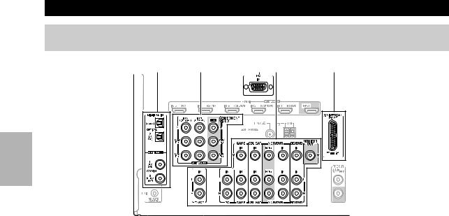
a DIGITAL IN OPTICAL and COAXIAL jacks b COMPONENT VIDEO IN and OUT jacks c HDMI IN and OUT jacks
d PC IN jack
e FM ANTENNA jack and AM ANTENNA terminal f MONITOR OUT V jack
g UNIVERSAL PORT jack h IR IN A/B and OUT jacks i 12V TRIGGER OUT jacks
jSPEAKERS terminals
(CENTER, FRONT, SURR)
k RS232 jack*
l ZONE 2 PRE OUT jacks m AC INLET jack
q
n uREMOTE CONTROL jack
oComposite video and analog audio jacks (BD/DVD IN, VCR/DVR IN and OUT, CBL/SAT IN, GAME IN, PC IN, TV/CD IN)
p PRE OUT: SUBWOOFER jacks q PRE OUT: SURR BACK jacks
See “Connecting the AV Receiver” for connection information ( 11 to 19).
*Terminal for control.
En
8
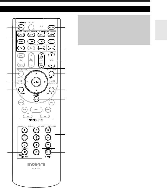
Remote Controller
Controlling the AV Receiver
a |
g |
|
c |
||
|
||
b |
|
|
|
h |
|
|
i |
|
|
d |
|
*2 |
*1 |
|
c |
|
|
a |
|
|
d |
j |
|
|
k |
e


e
f
b l
To control the AV receiver, press Receiver to select Receiver mode.
You can also use the remote controller to control your Blu-ray Disc/DVD player, CD player, and other components.
See “Entering Remote Control Codes” for more details ( 60).
For detailed information, see the pages in parentheses. a On/Standby button ( 20)
b Remote Mode/Input Selector buttons ( 21) c Arrow q/w/e/rand Enter buttons
d Setup button ( 35)
e Listening Mode buttons ( 29) f Dimmer button ( 21)
g Display button ( 21) h Muting button ( 22) i VOL q/wbutton ( 21) j Return button
k Home button ( 22) l Sleep button ( 22)
Controlling the tuner
To control the AV receiver’s tuner, press Tuner (or
Receiver).
You can select AM or FM by pressing Tuner repeatedly.
a Arrow q/wbuttons ( 26)
b D.TUN button ( 26)
c Display button
d CH +/– button ( 27)
e Number buttons ( 26)
*1 Video functions as a short cut of Home.
*2 This button does not change the effect of speaker.
En
9

About Home Theater
Enjoying Home Theater
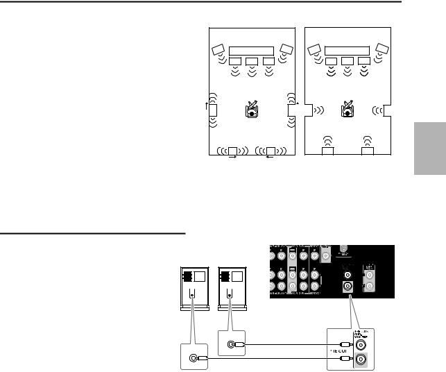
Thanks to the AV receiver’s superb capabilities, you can enjoy surround sound with a real sense of movement in your own home—just like being in a movie theater or concert hall. With Blu-ray Discs, you can enjoy DTS and Dolby Digital. With analog or digital TV, you can enjoy Dolby Pro Logic IIx, DTS Neo:6, or Onkyo’s original DSP listening modes. You can also enjoy THX Surround EX (THX-certified THX speaker system recommended).
ba
dc
Corner position
1/3 of wall position
aFront speakers
These output the overall sound. Their role in a home theater is to provide a solid anchor for the sound image. They should be positioned facing the listener at about ear level, and equidistant from the TV. Angle them inward so as to create a triangle, with the listener at the apex.
bCenter speaker
This speaker enhances the front speakers, making sound movements distinct and providing a full sound image. In movies it’s used mainly for dialog. Position it close to your TV facing forward at about ear level, or at the same height as the front speakers.
cSurround speakers
These speakers are used for precise sound positioning and to add realistic ambience. Position them at the sides of the listener, or slightly behind, about 2 to 3 feet (60 to 100 cm) above ear level. Ideally they should be equidistant from the listener.
dSurround back speakers
These speakers are necessary to enjoy Dolby Digital EX, DTS-ES Matrix, DTS-ES Discrete, THX Surround EX, etc. They enhance the realism of surround sound and improve sound localization behind the listener. Position them behind the listener about 2 to 3 feet (60 to 100 cm) above ear level.
eSubwoofer
The subwoofer handles the bass sounds of the LFE (Low-Frequency Effects) channel. The volume and quality of the bass output from your subwoofer will depend on its position, the shape of your listening room, and your listening position. In general, a good bass sound can be obtained by installing the subwoofer in a front corner, or at one-third the width of the wall, as shown.
Tip
•To find the best position for your subwoofer, while playing a movie or some music with good bass, experiment by placing your subwoofer at various positions within the room, and choose the one that provides the most satisfying results.
En
10
Connecting the AV Receiver
Connecting Your Speakers
Speaker Configuration
For 7.1-channel surround-sound playback, you need seven speakers and a powered subwoofer.
The following table shows which channels you should use based on the number of speakers you have.
Number of channels |
2 |
3 |
4 |
5 |
6 |
7 |
Front speakers |
|
|
|
|
|
|
|
|
|
|
|
|
|
Center speaker |
|
|
|
|
|
|
|
|
|
|
|
|
|
Surround speakers |
|
|
|
|
|
|
|
|
|
|
|
|
|
Surround back speaker* |
|
|
|
|
|
|
Surround back speakers |
|
|
|
|
|
|
*1 If you’re using only one surround back speaker, connect it to the power amplifier’s left terminals.
No matter how many speakers you use, a powered subwoofer is recommended for a powerful and solid bass. If you use surround back speakers, another power amplifier is necessary ( 12).
To get the best from your surround-sound system, you must set the speaker settings. You can do this automatically ( 24) or manually ( 37).
Attaching the Speaker Cable Labels
The AV receiver’s positive (+) speaker terminals are all red (the negative (–) speaker terminals are all black).
Speaker |
Color |
|
|
Front left |
White |
|
|
Front right |
Red |
|
|
Center |
Green |
|
|
Surround left |
Blue |
|
|
Surround right |
Gray |
|
|
Surround back left, Zone 2 left |
Brown |
|
|
Surround back right, Zone 2 right |
Tan |
|
|
The supplied speaker cable labels are also color-coded and you should attach them to the positive (+) side of each speaker cable in accordance with the table above. Then all you need to do is to match the color of each label to the corresponding speaker terminal.
Speaker Connection Precautions
Read the following before connecting your speakers:
•You can connect speakers with an impedance of between 6 and 16 ohms. If you use speakers with a lower impedance, and use the amplifier at high volume levels for a long period of time, the built-in amp protection circuit may be activated.
•Disconnect the power cord from the wall outlet before making any connections.
•Read the instructions supplied with your speakers.
•Pay close attention to speaker wiring polarity. In other words, connect positive (+) terminals only to positive (+) terminals, and negative (–) terminals only to negative (–) terminals. If you get them the wrong way around, the sound will be out of phase and will sound unnatural.
•Unnecessarily long, or very thin speaker cables may affect the sound quality and should be avoided.
•Be careful not to short the positive and negative wires. Doing so may damage the AV receiver.
•Don’t connect more than one cable to each speaker terminal. Doing so may damage the AV receiver.
•Don’t connect one speaker to several terminals.
En
11
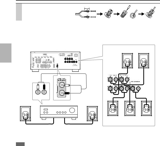
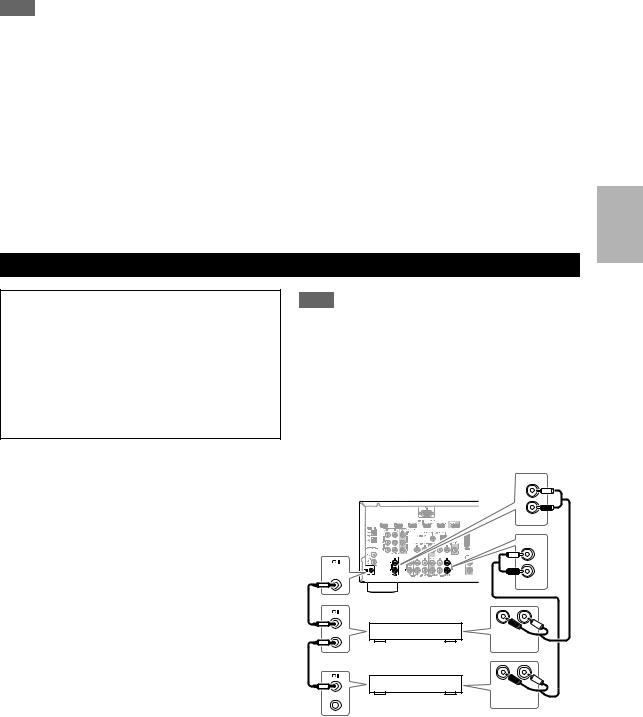
Connecting the Speaker Cables
Strip 1/2" to 5/8" (12 to 15 mm) of insulation from the ends of the speaker cables, and twist the bare wires tightly, as shown.
Using Banana Plugs
1/2" to 5/8"(12 to 15 mm)
•If you are using banana plugs, tighten the speaker terminal before inserting the banana plug.
•Do not insert the speaker code directly into the center hole of the speaker terminal.
The following illustration shows which speaker should be connected to each pair of terminals. If you’re using only one surround back speaker, connect it to the PRE OUT: SURR BACK jacks.
Surround right Surround left speaker speaker
L |
R |
|
Surround |
AUDIO |
|
INPUT |
||
back right |
Power amplifier |
|
speaker |
||
|
Surround |
|
|
back left |
|
|
speaker |
|
|
Front right |
Front left |
Center |
speaker |
speaker |
speaker |
Connect your Power amplifier’s analog audio output jacks to the AV receiver’s PRE OUT: SURR BACK jacks with an audio cable.
Note
• The speakers are configured by using “Speaker Setup” ( 37).
En
12
Using Dipole Speakers
You can use dipole speakers for the surround and surround back speakers. Dipole speakers output the same sound in two directions.
Dipole speakers typically have an arrow printed on them to indicate how they should be positioned. The surround dipole speakers should be positioned so that their arrows point toward the TV/screen, while the surround back dipole speakers should be positioned so that their arrows point toward each other, as shown.
aFront speakers bCenter speaker cSurround speakers dSurround back speakers eSubwoofer
Dipole speakers |
|
Normal speakers |
|
e TV/screen |
e |
e TV/screen |
e |
a |
b |
a |
a b |
a |
c |
c |
c |
c |
d |
d |
d |
d |
Connecting a Powered Subwoofer
Using a suitable cable, connect the AV receiver’s
SUBWOOFER PRE OUT jack to an input on your powered subwoofer, as shown. If your subwoofer is unpowered and you’re using an external amplifier, connect the SUBWOOFER PRE OUT jack to an input on the amp.
You can connect the powered subwoofer with two SUBWOOFER PRE OUT jacks respectively. The same signal is output from each jack.
Powered subwoofer
LINE INPUT
LINE INPUT
En
13
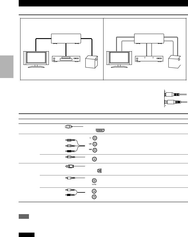
About AV Connections
Connected image with AV components
HDMI cable |
|
: Video & Audio |
|
AV receiver |
|
Blu-ray Disc/ |
|
TV, projector, etc. |
DVD player |
Game console |
Other cables |
|
: Video |
|
||
|
|
: Audio |
|
|
AV receiver |
|
|
|
|
|
|
|
|
|
|
|
|
|
|
|
|
|
|
|
|
|
|
|
|
|
|
|
|
|
|
|
|
|
|
|
|
|
Blu-ray Disc/ |
|
|
|
|||||||
|
|
|
|
||||||||
TV, projector, etc. |
Game console |
||||||||||
DVD player |
|||||||||||
•Before making any AV connections, read the manuals supplied with your AV components.
•Don’t connect the power cord until you’ve completed and double-checked all AV connections.
•Push plugs in all the way to make good connections (loose connections can cause noise or malfunctions).
•To prevent interference, keep audio and video cables away from power cords and speaker cables.
AV Cables and Jacks
 Right!
 Wrong!
Signal |
Cable |
Jack |
|
Description |
Video and |
HDMI |
|
HDMI |
HDMI connections can carry digital video and audio. |
Audio |
|
|
|
|
|
|
|
|
Video |
Component video |
Y |
Green |
|
|
||
|
|
PB/CB |
Blue |
|
|
PR/CR |
Red |
Component video separates the luminance (Y) and color difference signals (PB/CB, PR/CR), providing the best picture quality (some TV manufacturers label their component video sockets slightly differently).
Composite video |
Yellow |
Composite video is commonly used on TVs, VCRs, and |
V |
other video equipment. |
|
|
|
Audio |
Optical digital |
|
audio |
OPTICAL |
Optical digital connections allow you to enjoy digital |
||
|
|
|
sound such as PCM*, Dolby Digital or DTS. The audio |
|
|
|
|
|
|
|
quality is the same as coaxial. |
|
|
|
|
Coaxial digital |
Coaxial digital connections allow you to enjoy digital |
audio |
Orange sound such as PCM*, Dolby Digital or DTS. The audio |
|
quality is the same as optical. |
Analog audio (RCA)
L
R
White |
Analog audio connections (RCA) carry analog audio. |
|
|
Red |
|
*Available sampling rate for PCM input signal is 32/44.1/48/88.2/96 kHz. Even 176.4/192 kHz is effective in case of the HDMI connection.
Note
•The AV receiver does not support SCART plugs.
•The AV receiver’s optical digital jacks have shutter-type covers that open when an optical plug is inserted and close when it’s removed. Push plugs in all the way.
Caution
•To prevent shutter damage, hold the optical plug straight when inserting and removing.
En
14

Connecting Components with HDMI
VCR or DVD recorder/Digital Video Recorder
Game console
|
TV, projector, etc. |
Personal |
|
computer |
Blu-ray Disc/DVD player |
|
Satellite, cable, set-top box, etc.
Connect your components to the appropriate jacks. The default input assignments are shown below.: Assignment can be changed ( 36).
Jack |
|
Signal |
Components |
Assignable |
|
|
|
|
|
Input |
HDMI IN 1 |
Audio/Video |
Blu-ray Disc/DVD player |
|
|
|
|
|
|
|
HDMI IN 2 |
|
VCR or DVD recorder/Digital Video Recorder |
|
|
|
|
|
|
|
HDMI IN 3 |
|
Satellite, cable, set-top box, etc. |
|
|
|
|
|
|
|
HDMI IN 4 |
|
Game console |
|
|
|
|
|
|
|
HDMI IN 5 |
|
Personal computer |
|
|
|
|
|
|
Output |
HDMI OUT |
|
TV, projector, etc. |
|
|
|
|
|
|
Refer to “About HDMI” ( 68) and “Using an RIHD-compatible TV, Player, or Recorder” ( 69).
Audio return channel (ARC) function
Audio return channel (ARC) function enables an HDMI capable TV to send the audio stream to the HDMI OUT of the AV receiver. To use this function, you must select the TV/CD input selector.
•To use ARC function, you must select the TV/CD input selector, your TV must support ARC function and “HDMI Control” is set to “On”( 47).
Tip
To listen to audio received by the HDMI IN jacks through your TV’s speakers:
•Set the “TV Control” setting to “On” ( 48) for an p-compatible TV.
•Set the “Audio TV Out” setting to “On” ( 47) when the TV is not compatible with por the “TV Control” setting to “Off”.
•Set your Blu-ray Disc/DVD player’s HDMI audio output setting to PCM.
•To listen to TV audio through the AV receiver, see “Connecting External Components” ( 16).
Note
•When listening to an HDMI component through the AV receiver, set the HDMI component so that its video can be seen on the TV screen (on the TV, select the input of the HDMI component connected to the AV receiver). If the TV power is off or the TV is set to another input source, this may result in no sound from the AV receiver or the sound may be cut off.
•When the “Audio TV Out” setting is set to “On” ( 47) to hear from your TV’s speakers, by controlling the AV receiver’s volume, the sound will be output from the AV receiver’s speakers, too. When the “TV Control” setting is set to “On” ( 48) to hear from speakers of p-compatible TV, by controlling the AV receiver’s volume, the AV receiver’s speakers will produce sound while the TV’s speakers are muted. To stop the AV receiver’s speakers producing sound, change the settings, change your TV’s settings, or turn down the AV receiver’s volume.
En
15
Connecting External Components
The on-screen setup menus appear only on a TV that is connected to the HDMI OUT. If your TV is connected to the MONITOR OUT V or the COMPONENT VIDEO OUT, use the AV receiver’s display when changing settings.
B A E C D
Connect your components to the appropriate jacks. The default input assignments are shown below.: Assignment can be changed ( 37).
No. |
Jack |
|
|
Signal |
Components |
Assignable |
|
|
|
|
|
|
|
|
|
A |
COMPONENT |
|
IN 1 (BD/DVD) |
|
Component video |
Blu-ray Disc/DVD player |
|
|
VIDEO |
|
|
|
|
|
|
|
|
IN 2 (CBL/SAT) |
|
|
Satellite, cable, set-top box, etc. |
|
|
|
|
|
|
|
|||
|
|
|
|
|
|
|
|
|
|
|
OUT |
|
|
TV, projector, etc. |
|
|
|
|
|
|
|
|
|
B |
DIGITAL IN |
|
OPTICAL |
IN 1 (GAME) |
Digital audio |
Game console |
|
|
|
|
|
|
|
|
|
|
|
|
|
IN 2 (TV/CD) |
|
TV, CD player |
|
|
|
|
|
|
|
|
|
|
|
|
COAXIAL |
IN 1 (BD/DVD) |
|
Blu-ray Disc/DVD player |
|
|
|
|
|
|
|
|
|
|
|
|
|
IN 2 (CBL/SAT) |
|
Satellite, cable, set-top box, etc. |
|
|
|
|
|
|
|
|
|
C |
MONITOR OUT |
|
|
Composite video |
TV, projector, etc. |
|
|
|
|
|
|
|
|
|
|
|
BD/DVD IN |
|
|
Analog audio and |
Blu-ray Disc/DVD player |
|
|
|
|
|
|
|
composite video |
|
|
|
VCR/DVR IN |
|
|
VCR or DVD recorder/Digital |
|
||
|
|
|
|
|
|||
|
|
|
|
|
|
Video Recorder |
|
|
|
|
|
|
|
|
|
|
CBL/SAT IN |
|
|
|
Satellite, cable, set-top box, etc. |
|
|
|
|
|
|
|
|
|
|
|
GAME IN |
|
|
|
Game console |
|
|
|
|
|
|
|
|
|
|
|
PC IN |
|
|
Analog audio |
Personal computer |
|
|
|
|
|
|
|
|
|
|
|
TV/CD IN |
|
|
|
TV, CD player, Turntable*1, |
|
|
|
|
|
|
|
|
Cassette tape deck, MD, CD-R |
|
|
|
|
|
|
|
||
D |
UNIVERSAL PORT |
|
Analog audio/ |
Universal port optional dock |
|
||
|
|
|
|
|
Video |
(UP-A1 etc.) |
|
|
|
|
|
|
|
|
|
E |
PC IN |
|
|
Analog RGB |
Personal computer |
*2 |
|
|
|
|
|
|
|
|
|
En
16
Note
*1 Connect a turntable (MM) that has a phono preamp built-in. If your turntable (MM) doesn’t have it, you’ll need a commercially available phono preamp. If your turntable has a moving coil (MC) type cartridge, you’ll need a commercially available MC head amp or MC transformer as well as a phono preamp. See your turntable’s manual for details.
*2 When you connect your personal computer to PC IN and select PC Input selector, video of the personal computer is output from HDMI OUT. However, if you have assigned HDMI IN to the PC input selector, the AV receiver will output signals from HDMI IN instead of signals from PC IN. To get the signals output from PC IN, select “- - - - -” for “PC” in the “HDMI Input” setting
( 36).
•With connection C, you can listen and record audio from the external components while you are in Zone 2. You can listen and record audio from the external components in the main room; you can listen to the audio in Zone 2 as well.
•With connection B, you can enjoy Dolby Digital and DTS. (To record or listen in Zone 2 as well, use B and C.)
•With connection C, if your Blu-ray Disc/DVD player has both the main stereo and multichannel outputs, be sure to connect the main stereo.
How to record the video
With the connections described above, you cannot record the video through the AV receiver. To make a connection for video recording ( 28).
.
Connecting Integra/Onkyo uComponents
Step 1:
Make sure that each Integra/Onkyo component is connected with an analog audio cable (connection C in the hookup examples) ( 16).
Step 2:
Make the uconnection (see illustration below).
Step 3:
If you’re using an RI Dock, or cassette tape deck, change the Input Display ( 23).
With u(Remote Interactive), you can use the following special functions:
System On/Auto Power On
When you start playback on a component connected via uwhile the AV receiver is on Standby, the AV receiver will automatically turn on and select that component as the input source.
Direct Change
When playback is started on a component connected via u, the AV receiver automatically selects that component as the input source.
Remote Control
You can use the AV receiver’s remote controller to control your other u-capable Integra/Onkyo components, pointing the remote controller at the AV receiver’s remote control sensor instead of the component. You must enter the appropriate remote control code first ( 60).
Note
•Use only ucables for uconnections. ucables are supplied with Integra/Onkyo players (DVD, CD, etc.).
•Some components have two ujacks. You can connect either one to the AV receiver. The other jack is for connecting additional u-capable components.
•Connect only Integra/Onkyo components to ujacks. Connecting other manufacturer’s components may cause a malfunction.
•Some components may not support all functions. Refer to the manuals supplied with your other Integra/Onkyo components.
•While Zone 2 is on, the System On/Auto Power On and Direct Change ufunctions do not work.
IN
L
R
|
|
TV/CD |
|
|
IN |
|
|
L |
REMOTE |
|
R |
CONTROL |
|
|
|
|
|
|
|
BD/DVD |
|
R |
L |
e.g., CD player |
ANALOG |
|
AUDIO OUT |
||
|
|
|
|
R |
L |
e.g., DVD player |
ANALOG |
|
AUDIO OUT |
||
En
17
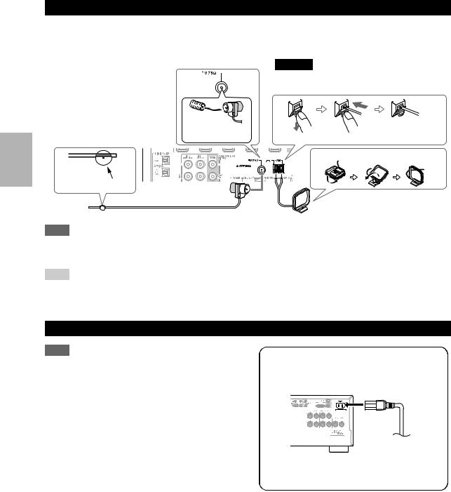
Connecting Antenna
This section explains how to connect the supplied indoor FM antenna and AM loop antenna.
The AV receiver won’t pick up any radio signals without any antenna connected, so you must connect the antenna to use the tuner.
Caution
• Be careful that you don’t injure yourself when using thumbtacks.
Insert the plug fully |
|
|
|
into the jack. |
Push. |
Insert wire. |
Release. |
Assembling the AM loop antenna
Thumbtacks, etc.
Indoor FM antenna (supplied) 
 AM loop antenna (supplied)
Note
•Once your AV receiver is ready for use, you’ll need to tune into a radio station and position the antenna to achieve the best possible reception.
•Keep the AM loop antenna as far away as possible from your AV receiver, TV, speaker cables, and power cords.
Tip
•If you cannot achieve good reception with the supplied indoor FM antenna, try a commercially available outdoor FM antenna instead.
•If you cannot achieve good reception with the supplied indoor AM loop antenna, try using it with a commercially available outdoor AM antenna.
Connecting the Power Cord
Note
•Before connecting the power cord, connect all of your speakers and AV components.
•Turning on the AV receiver may cause a momentary power surge that might interfere with other electrical equipment on the same circuit. If this is a problem, plug the AV receiver into a different branch circuit.
•Do not use a power cord other than the one supplied with the AV receiver. The supplied power cord is designed exclusively for use with the AV receiver and should not be used with any other equipment.
•Never disconnect the power cord from the AV receiver while the other end is still plugged into a wall outlet. Doing so may cause an electric shock. Always disconnect the power cord from the wall outlet first, and then the AV receiver.
Step 1:
Connect the supplied power cord to the AV receiver’s AC INLET.
To AC wall outlet
Step 2:
Plug the power cord into an AC wall outlet.
En
18
Which Connections Should I Use?
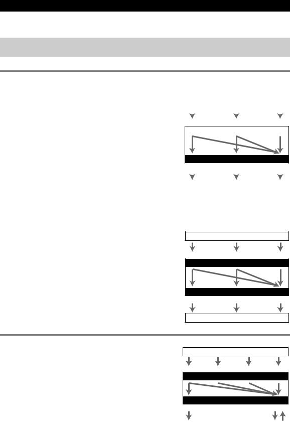
The AV receiver supports several connection formats for compatibility with a wide range of AV equipment. The format you choose will depend on the formats supported by your components. Use the following sections as a guide.
The on-screen setup menus appear only on a TV that is connected to the HDMI OUT. If your TV is connected to the MONITOR OUT V or the COMPONENT VIDEO OUT, use the AV receiver’s display when changing settings.
Video Connection Formats
Video component can be connected by using any one of the following video connection formats: composite video, component video, or HDMI, the latter offering the best picture quality.
For optimal video performance, THX recommends that video signals pass through the system without upconversion (e.g., component video input through to component video output).
It is also recommended that you press VCR/DVR and Return on the AV receiver at the same time. Select “Skip” in the “VProcessor(video processor)” setting by pressing Return repeatedly on the display. To reset back to the original setting, press the same button at the same time.
|
|
|
|
|
|
|
|
|
|
|
|
|
|
|
|
|
|
|
|
|
|
|
|
|
|
|
|
|
|
|
|
|
|
|
|
Composite |
Component |
HDMI |
|
|||||
|
|
|
|
|
|
|
|
|
|
|
|
|
|
|
|
|
|
AV receiver
Video input signals flow through the AV receiver as shown,
with composite video and component video sources all being |
Composite |
Component |
HDMI |
||||
|
|
|
|
|
|
|
|
upconverted for the HDMI output. |
|
|
|
|
|
|
|
|
|
|
|
|
|
|
|
The composite video and component video outputs pass |
|
|
|
|
|
|
|
|
|
|
TV, projector, etc. |
|
|
||
through their respective input signals as they are. |
|
|
|
|
|
|
|
|
|
|
|
|
|
|
|
When you connect audio component to an HDMI or COMPONENT input, you must assign that input to an input selector ( 36).
Signal Selection
If signals are present at more than one input, the inputs will be selected automatically in the following order of priority: HDMI, component video, composite video.
However, for component video only, regardless of whether a component video signal is actually present, if a component video input is assigned to the input selector, that component video input will be selected. And if no component video input is assigned to the input selector, this will be interpreted as no component video signal being present.
In the Signal Selection Example shown on the right, video signals are present at both the HDMI and composite video inputs, however, the HDMI signal is automatically selected as the source and video is output by the HDMI outputs.
Signal Selection Example
Blu-ray Disc/DVD player, etc.
Composite |
Component |
HDMI |
|
IN |
|
AV receiver |
|
|
|
MONITOR OUT |
|
Composite |
Component |
HDMI |
TV, projector, etc.
Audio Connection Formats
Audio component can be connected by using any of the following audio connection formats: analog, optical, coaxial, or HDMI.
When choosing a connection format, bear in mind that the AV receiver does not convert digital input signals for analog line outputs and vice versa. For example, audio signals connected to an optical or coaxial digital input are not output by the analog VCR/DVR OUT.
If signals are present at more than one input, the inputs will be selected automatically in the following order of priority: HDMI, digital, analog.
|
|
|
Audio Signal Flow Chart |
|
|
|
|
|
Blu-ray Disc/DVD player, etc. |
|
|
||
|
Analog |
|
Optical |
Coaxial |
HDMI |
|
|
|
|
IN |
|
|
|
AV receiver |
*1 |
*1 |
*1 |
|
|
|
|
|
|
|
|||
|
|
|
OUT |
|
|
|
|
Analog |
|
|
|
HDMI |
|
|
|
|
|
|
*1 |
*2 |
|
|
TV, projector, etc. |
|
|
|
|
|
*1 |
Depends on the “Audio TV Out” setting ( 47). |
|
|
*2 |
This setting is available, when “Audio Return Ch” setting |
|
|
|
is set to “Auto” ( 47), you must select the TV/CD input |
En |
|
|
selector and your TV must support ARC function. |
19 |
|
|
|
|
|

Turning On/Off the AV Receiver
On/Standby
Standby indicator
On/Standby 


Receiver
Front panel |
Remote controller |
Turning On
Press On/Standby on the front panel. or
Press Receiver followed by On/Standby on the remote controller.
The AV receiver comes on, the display lights, and the Standby indicator goes off.
Turning Off
Press On/Standby on the front panel or the remote controller.
The AV receiver will enter Standby mode. To prevent any loud surprises when you turn on the AV receiver, always turn down the volume before you turn it off.
En
20
Basic Operations
The on-screen menus appear only on a TV that is connected to the HDMI OUT. If your TV is connected to the MONITOR OUT V or the COMPONENT VIDEO OUT, use the AV receiver’s display when changing settings.
This manual describes the procedure using the remote controller unless otherwise specified.
Selecting the Language Used for the Onscreen Setup Menus
You can determine the language used for the onscreen setup menus. See “OSD Setup” ( 46).
Playing the Connected Component
Operating on the AV receiver
1Use the input selector buttons to select the input source.
2Start playback on the source component.
See also:
•“Controlling Other Components” ( 59)
•“Controlling iPod” ( 55)
•“Listening to the Radio” ( 26)
3To adjust the volume, use the Master Volume control.
4Select a listening mode and enjoy!
See also:
•“Using the Listening Modes” ( 29)
•“Audyssey” ( 41)
Operating with the remote controller
1Press Receiver followed by Input Selector.
2Start playback on the source component.
See also:
•“Controlling Other Components” ( 59)
•“Controlling iPod” ( 55)
•“Listening to the Radio” ( 26)
3To adjust the volume, use VOL q/w.
4Select a listening mode and enjoy!
See also:
•“Using the Listening Modes” ( 29)
•“Audyssey” ( 41)
Displaying Source Information
You can display various information about the current input source as follows. (Components connected to the UNIVERSAL PORT jack are excluded.)
Press Receiver followed by Display repeatedly to cycle through the available information.
Tip
• Alternatively, you can use the AV receiver’s Display.
The following information can typically be displayed.
Input source & volume*1
Signal format*2 or sampling fre- 


 quency
Input & output resolution
Input source & listening mode*3 


*1 When AM or FM radio is used, the band, preset number, and frequency are displayed.
*2 If the input signal is analog, no format information is displayed. If the input signal is PCM, the sampling frequency is displayed. If the input signal is digital but not PCM, the signal format is displayed.
Information is displayed for about three seconds, then the previously displayed information reappears.
*3 The input source is displayed with the default name even when you have entered a name in “Name Edit” ( 43).
Setting the Display Brightness
You can adjust the brightness of the AV receiver’s display.
Press Receiver followed by Dimmer repeatedly to select: dim, dimmer, or normal brightness.
Tip
• Alternatively, you can use the AV receiver’s Dimmer.
En
21

Muting the AV Receiver
You can temporarily mute the output of the AV receiver.
Press Receiver followed by Muting.
The output is muted and the MUTING indicator flashes on the display.
Tip
•To unmute, press Muting again or adjust the volume.
•The Mute function is cancelled when the AV receiver is set to Standby.
Using the Sleep Timer
With the sleep timer, you can set the AV receiver to turn off automatically after a specified period.
Press Receiver followed by Sleep repeatedly to select the required sleep time.
The sleep time can be set from 90 to 10 minutes in 10 minute steps.
The SLEEP indicator lights on the display when the sleep timer has been set. The specified sleep time appears on the display for about five seconds, then the previous display reappears.
Tip
•If you need to cancel the sleep timer, press Sleep repeatedly until the SLEEP indicator goes off.
•To check the time remaining until the AV receiver sleeps, press Sleep. Note that if you press Sleep while the sleep time is being displayed, you’ll shorten the sleep time by 10 minutes.
Using the Home Menu
The Home menu provides you quick access to frequently used menus without having to go through the long standard menu. This menu enables you to change settings and view the current information.
1 Press Receiver followed by Home.
The following information will be superimposed on the TV screen.
BD/DVD
Audio |
Bass |
0dB |
Video |
Treble |
|
Info |
Subwoofer Level |
|
Input Sel |
Center Level |
|
Listening Mode |
Dynamic EQ |
|
|
Dynamic Volume |
|
2 Use q/w/e/rto make the desired selection. `Audio*1
You can change the following settings: “Bass”, “Treble”, “Subwoofer Level”, “Center Level”, “Dynamic EQ”, “Dynamic Volume”, “Late Night”, “Music Optimizer”, “Re-EQ”, “Re-EQ(THX)”, and “Audio Selector”.
See also:
•“Audyssey” ( 41)
•“Using the Audio Settings” ( 48)
`Video*2
You can change the following settings: “Wide Mode” and “Picture Mode”. The remote controller’s Video acts as a shortcut for this menu.
See also:
• “Picture Adjust” ( 43)
`Info*3*4
You can view the information of the following items: “Audio”, “Video”, and “Tuner”.
`Input*4*5
You can select the input source while viewing the information as follows: the name of input selectors, input assignments, and radio information, and ARC function setting.
Press Enter to display the current input source, followed by q/wto select the desired input source. Pressing Enter again switches to the selected input source.
`Listening Mode
You can select the listening modes that are grouped in the following categories: MOVIE/ TV, MUSIC, GAME, and THX.
Use q/wto select the category and e/rto select the listening mode. Press Enter to switch to the selected listening mode.
Note
*1 If Direct listening mode is selected, “Dynamic EQ” and “Dynamic Volume” cannot be selected.
*2 Only when you have selected “Custom” in the “Picture Mode” ( 44), pressing Enter allows you to adjust the following items via the Home menu; “Brightness”, “Contrast”, “Hue”, and “Saturation”. Press Return to return to the original Home menu.
*3 Depending on the input source and listening mode, not all channels shown here output the sound.
*4 When you have entered a custom name in “Name Edit” ( 43), the input source is displayed with that name. But
even if not, the component name may be displayed if the AV receiver receives it via HDMI connection ( 15).
*5 For the Port input selector, the name of Universal Port Option Dock will be displayed.
En
22
Loading...