


A / V Receiver
DTR-7
DTR-6
Instruction Manual
|
|
|
|
|
FM MUTE/ |
|
|
CHARACTER/ |
SP/SYS |
AUDIO |
BASS/ |
|
|
MASTER VOLUME |
|
||
|
DIMMER |
|
|
|
MODE |
DOWN |
TUNING |
UP |
MEMORY |
SETUP |
ADJUSTMENT |
TREBLE |
|
|
|
|
|
STANDBY/ON |
|
|
|
|
|
|
|
|
|
|
|
|
|
|
|
|
|
|
|
|
|
|
|
|
|
|
|
MODE |
|
W |
N |
|
|
|
|
|
|
|
|
|
|
|
|
|
|
|
|
D O |
|
|
|
U |
|
|
|
|
|
|
|
|
|
|
|
PRESET/MODE ADJ |
|
|
|
|
P |
||
SANDBY MULTI SOURCE |
|
|
|
|
|
|
|
|
|
|
|
|
|
|
|
|
|
POWER |
|
|
|
|
|
|
|
|
|
|
|
|
|
|
|
|
|
ON OFF |
|
|
|
|
|
|
|
|
|
PUSH TO ENTER |
|
|
|
|
|
|
|
A SPEAKERS B |
|
|
|
|
LISTENING MODE |
|
|
|
REC OUT/ |
DIGITAL/ |
|
|
|
|
|
|
|
DISPLAY |
|
|
DIRECT |
STEREO |
/DTS |
THX |
|
DSP |
MULTI SOURCE |
ANALOG CH LEVEL |
|
|
|
|
|
||
|
|
|
|
|
|
SURROUND |
|
|
|
MODE |
|
|
|
|
|
|
|
PHONES |
MULTI CH INPUT |
|
|
|
|
|
|
|
|
|
|
|
|
|
|
VIDEO 4 |
(MONO) |
|
DVD |
VIDEO-1 |
VIDEO-2 |
VIDEO-3 |
VIDEO-4 |
TAPE |
FM |
AM |
PHONO |
C D |
|
|
|
|
|
||
|
|
|
|
|
|
|
|
|
|
|
|
|
S VIDEO |
VIDEO |
L AUDIO |
R(MONO) |
|
DTR-7 by 


Thank you for purchasing the Integra Audio Video Control Receiver.
Please read this manual thoroughly before making connections and turning on the power.
Following the instructions in this manual will enable you to obtain optimum performance and listening enjoyment from your new Audio Video Control Receiver.
Please retain this manual for future reference.
Contents |
|
Before using |
|
Important Safeguards ........................................ |
2 |
Precautions ........................................................ |
3 |
Features ............................................................. |
4 |
Supplied accessories ......................................... |
4 |
Before operating this unit ................................. |
5 |
Preparation |
|
Audio equipment connections .......................... |
6 |
Video equipment connections ........................... |
8 |
Connecting equipment |
|
with 5.1-channel output .................................. |
9 |
Connecting speakers ....................................... |
10 |
Connecting power amplifiers .......................... |
12 |
Connecting an equalizer .................................. |
13 |
Connecting the power ..................................... |
13 |
Making antenna connections .......................... |
14 |
Operation |
|
Using the on-screen display ............................ |
16 |
Setting the speaker configuration ................... |
18 |
Setting the speaker distance ............................ |
20 |
Setting the speaker Level ................................ |
21 |
Playing a digital source ................................... |
23 |
Presetting FM/AM radio stations .................... |
24 |
Selecting an input source ................................ |
26 |
Selecting a preset station ................................. |
32 |
Playing a multichannel input source ............... |
33 |
Using the Listening Modes ............................. |
34 |
Setting the listening mode parameters .................... |
38 |
Assigning a video source |
|
to each audio input source .............................. |
40 |
Giving a name to each input source |
|
and preset radio station ................................... |
41 |
Adjusting the output level of each speaker |
|
while listening to it ......................................... |
42 |
Other setup operations .................................... |
43 |
Recording a source .......................................... |
44 |
Using Multi-Room Remote System ................ |
46 |
The initial settings ........................................... |
48 |
Appendix |
|
Using the remote controller ............................ |
49 |
Programming the remote controller codes of |
|
other devices into the RC-392M ..................... |
52 |
Using a Macro function .................................. |
54 |
Troubleshooting guide .................................... |
58 |
Specifications .................................................. |
60 |
Control positions and names ........................... |
62 |
WARNING:
TO REDUCE THE RISK OF FIRE OR ELECTRIC SHOCK, DO NOT EXPOSE THIS APPLIANCE TO RAIN OR MOISTURE.
CAUTION:
TO REDUCE THE RISK OF ELECTRIC SHOCK, DO NOT REMOVE COVER (OR BACK). NO USER-SERVICEABLE PARTS INSIDE. REFER SERVICING TO QUALIFIED SERVICE PERSONNEL.
WARNING |
|
AVIS |
RISK OF ELECTRIC SHOCK |
|
RISQUE DE CHOC ELECTRIQUE |
DO NOT OPEN |
|
NE PAS OUVRIR |
|
|
|
The lightning flash with arrowhead symbol, within an equilateral triangle, is intended to alert the user to the presence of uninsulated “dangerous voltage” within the product’s enclosure that may be of sufficient magnitude to constitute a risk of electric shock to persons.
The exclamation point within an equilateral triangle is intended to alert the user to the presence of important operating and maintenance (servicing) instructions in the literature accompanying the appliance.
Important Safeguards
1.Read Instructions – All the safety and operating instructions should be read before the appliance is operated.
2.Retain Instructions – The safety and operating instructions should be retained for future reference.
3.Heed Warnings – All warnings on the appliance and in the operating instructions should be adhered to.
4.Follow Instructions – All operating and use instructions should be followed.
5.Water and Moisture – The appliance should not be used near water – for example, near a bathtub, washbowl, kitchen sink, laundry tub, in a wet basement, or near a swimming pool, and the like.
6.Carts and Stands – The appliance
should be used only with a cart or stand that is recommended by the manufacturer.
6A.An appliance and cart combination should be moved with care. Quick stops, excessive force, and uneven sur-
faces may cause the appliance and cart S3125A combination to overturn.
7.Wall or Ceiling Mounting – The appliance should be mounted to a wall or ceiling only as recommended by the manufacturer.
8.Ventilation – The appliance should be situated so that its location or position does not interfere with its proper ventilation. For example, the appliance should not be situated on a bed, sofa, rug, or similar surface that may block the ventilation openings; or if placed in a built-in installation, such as a bookcase or cabinet that may impede the flow of air through the ventilation openings, there should be free space of at least 20 cm (8 in.) and an opening behind the appliance.
9.Heat – The appliance should be situated away from heat sources such as radiators, heat registers, stoves, or other appliances (including amplifiers) that produce heat.
10.Power Sources – The appliance should be connected to a power supply only of the type described in the operating instructions or as marked on the appliance.
11.Polarization – If the appliance is provided with a polarized plug having one blade wider than the other, please read the following information:
The polarization of the plug is a safety feature. The polarized plug will only fit the outlet one way. If the plug does not fit fully into the outlet, try reversing it. If there is still trouble, the user should seek the services of a qualified electrician. Under no circumstances should the user attempt to defeat the polarization of the plug.
12.Power-Cord Protection – Power-supply cords should be routed so that they are not likely to be walked on or pinched by items placed upon or against them, especially near plugs, convenience receptacles, and the point where they exit from the appliance.
13.Cleaning – The appliance should be cleaned only as recommended by the manufacturer.
14.Power Lines – An outdoor antenna should be located away from power lines.
15.Nonuse Periods – The power cord of the appliance should be unplugged from the outlet when left unused for a long period of time.
16.Object and Liquid Entry – Care should be taken so that objects do not fall and liquids are not spilled into the enclosure through openings.
17.Damage Requiring Service – The appliance should be serviced by qualified service personnel when:
A.The power-supply cord or the plug has been damaged; or
B.Objects have fallen, or liquid has been spilled into the appliance; or
C.The appliance has been exposed to rain; or
D.The appliance does not appear to operate normally or exhibits a marked change in performance; or
E.The appliance has been dropped, or the enclosure damaged.
18.Servicing – The user should not attempt to service the appliance beyond that described in the operating instructions. All other servicing should be referred to qualified service personnel.
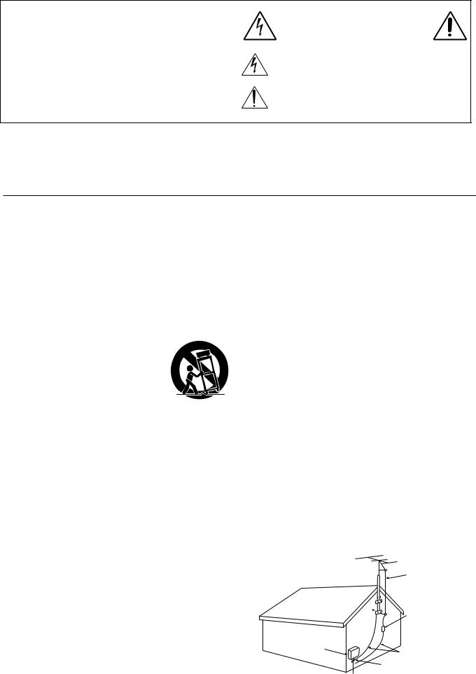
19.Outdoor Antenna Grounding – If an outside antenna is connected to the receiver, be sure the antenna system is grounded so as to provide some protection against voltage surges and built up static charges. Article 810 of the National Electrical Code, ANSI/NFPA 70, provides information with regard to proper grounding of the mast and supporting structure, grounding of the lead-in wire to an antenna-discharge unit, size of grounding conductors, location of antenna-discharge unit, connection to grounding electrodes, and requirements for the grounding electrode. See Figure 1.
FIGURE 1:
EXAMPLE OF ANTENNA GROUNDING AS PER NATIONAL ELECTRICAL CODE
ANTENNA
LEAD IN
WIRE
GROUND  CLAMP
CLAMP 
ANTENNA DISCHARGE UNIT (NEC SECTION 810-20)
ELECTRIC
SERVICE
EQUIPMENT
GROUNDING CONDUCTORS (NEC SECTION 810-21)

 GROUND CLAMPS

 POWER SERVICE GROUNDING
ELECTRODE SYSTEM
(NEC ART 250, PART H)
NEC – NATIONAL ELECTRICAL CODE
S2898A
2

Precautions
1. Warranty Claim
You can find the serial number on the rear panel of this unit. In case of warranty claim, please report this number.
2. Recording Copyright
Recording of copyrighted material for other than personal use is illegal without permission of the copyright holder.
3. AC Fuse
The fuse is located inside the chassis and is not user-serviceable. If power does not come on, contact your Onkyo authorized service station.
4. Care
From time to time you should wipe the front and rear panels and the cabinet with a soft cloth. For heavier dirt, dampen a soft cloth in a weak solution of mild detergent and water, wring it out dry, and wipe off the dirt. Following this, dry immediately with a clean cloth. Do not use rough material, thinners, alcohol or other chemical solvents or cloths since these could damage the finish or remove the panel lettering.
5. Power
WARNING
BEFORE PLUGGING IN THE UNIT FOR THE FIRST TIME, READ THE FOLLOWING SECTION CAREFULLY.
The voltage of the available power supply differs according to country or region. Be sure that the power supply voltage of the area where this unit will be used meets the required voltage (e.g., AC 230 V, 50 Hz or AC 120 V, 60 Hz) written on the rear panel.
Worldwide models are equipped with a voltage selector to conform to local power supplies. Be sure to set this switch to match the voltage of the power supply in your area before plugging in the unit.
Note to CATV system installer:
This reminder is provided to call the CATV system installer’s attention to Article 820-40 of the NEC, ANSI/NFPA 70, which provides guidelines for proper grounding and, in particular, specifies that the cable ground shall be connected to the grounding system of the building, as close to the point of cable entry as practical.
FCC Information for User
CAUTION:
The user changes or modifications not expressly approved by the party responsible for compliance could void the user’s authority to operate the equipment.
NOTE:
This equipment has been tested and found to comply with the limits for a Class B digital device, pursuant to Part 15 of the FCC Rules. These limits are designed to provide reasonable protection against harmful interference in a residential installation. This equipment generates, uses and can radiate radio frequency energy and, if not installed and used in accordance with the instructions, may cause harmful interference to radio communications. However, there is no guarantee that interference will not occur in a particular installation. If this equipment does cause harmful interference to radio or television reception, which can be determined by turning the equipment off and on, the user is encouraged to try to correct the interference by one or more of the following measures:
•Reorient or relocate the receiving antenna.
•Increase the separation between the equipment and receiver.
•Connect the equipment into an outlet on a circuit different from that to which the receiver is connected.
•Consult the dealer or an experienced radio/TV technician for help.
For Canadian model
CAUTION: THIS DIGITAL APPARATUS DOES NOT EXCEED THE CLASS B LIMITS FOR RADIO NOISE EMISSION FROM DIGITAL APPARATUS SET OUT IN THE RADIO INTERFERENCE REGULATIONS OF THE CANADIAN DEPARTMENT OF COMMUNICATIONS.
For models having a power cord with a polarized plug: CAUTION: TO PREVENT ELECTRIC SHOCK, MATCH WIDE BLADE OF PLUG TO WIDE SLOT, FULLY INSERT.
Modele pour les Canadien
ATTENTION: L'INTERFÉRENCE RADIO ÉLECTRIQUE GÉNÉRÉE PAR CET APPAREIL NUMÉRIQUE DE TYPE B NE DÉPASSE PAS LES LIMITES ÉNONCÉES DANS LE RÈGLEMENT SUR LES PERTURBATIONS RADIO ÉLECTRIQUES, SECTION APPAREIL NUMÉRIQUE, DU MINISTÈRE DES COMMUNICATIONS.
Sur les modèles dont la fiche est polarisée:
ATTENTION: POUR ÉVITER LES CHOCS ÉLECTRIQUES, INTRODUIRE LA LAME LA PLUS LARGE DE LA FICHE DANS LA BORNE CORRESPONDANTE DE LA PRISE ET POUSSER JUSQU’AU FOND.
3
Features |
|
Supplied accessories |
Key Features
■THX*1 select (DTR-7 only)
■DTS*2 decorder built-in
■Dolby*3 digital decoder built-in
■Linear PCM 96 kHz/24-bit D/A converter
■5.1 multichannel inputs
■4 assignable digital inputs (2-coaxial, 2-optical)
■Optical digital output (DTR-7 only)
■Onscreen display
■Main-in jacks for front left & right channels (DTR-7 only)
■Pre outs for all channels
■Banana-plug posts for all channels
■Aluminum volume control
■New user-friendly smart scan
■New backlit learning remote with joy stick
■3 audio and 5 AV inputs (all S-video&video)
■Cinema Re-EQ*4
■Multiroom Jack for compatibility with Xantech*5, Niles*6, and the more popular multiroom A/V distribution and control systems.
Amplifier Design
■5-channel amplification
■Real high-current, 6 Ω low-impedance drive
■DVD-audio capability
■Wide Range amplifier technology
■Discrete output stage circuits for all channels
■High-quality extruded heat sink
■Oversized power transformer
■(DTR-7)
105 W x 5 (8 Ω 20 Hz-20 kHz 0.08% THD FTC) 135 W x 5 (6 Ω 1 kHz 0.1% THD FTC)
■(DTR-6)
85 W x 5 (8 Ω 20 Hz-20 kHz 0.08% THD FTC) 110 W x 5 (6 Ω 1 kHz 0.1% THD FTC)
*1 Lucasfilm and THX are registered trademarks of Lucasfilm LTD.
*2 Manufactured under license from Digital Theater Systems, Inc. US Pat. No.5,451,942 and other worldwide patents issues and pending. “DTS” and “DTS Digital Surround” are trademarks of Digital Theater Systems, Inc.© 1996 Digital Theater Systems, Inc. All rights reserved.
*3 Manufactured under license from Dolby Laboratories.
“Dolby”, “Pro Logic” and the double-D symbol are trademarks of Dolby Laboratories. Confidential Unpublished Works. ©1992-1997 Dolby Laboratories, Inc. All rights reserved.
*4 Re-Equalization and the “Re-EQ” logo are trademarks of Lucasfilm Ltd. Manufactured under license of Lucasfilm Ltd.
*5 Xantech is a registered trademark of Xantech Corporation. *6 Niles is a registered trademark of Niles Audio Corporation.
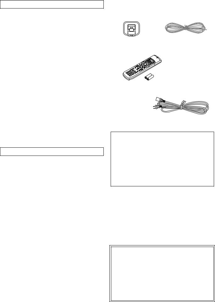
Check that the following accessories are supplied with this unit.
AM loop antenna x 1
Remote controller (RC-392M) x1 Batteries (size AA or UM-3) x 2
FM antenna x 1
(Connector shape may vary depending on where the unit is purchased.)
Power cable x1
Memory Preservation
This unit does not require memory preservation batteries. A built-in memory power back-up system preserves the contents of the memory during power failures and even when the POWER switch is set to off. The POWER switch must be set to on in order to charge the back-up system.
The memory preservation period after the unit has been turned off varies depending on climate and placement of the unit. On the average, memory contents are protected over a period of a few weeks after the last time the unit has been turned off . This period is shorter when the unit is exposed to a highly humid climate.
THX Select
Before any home theatre component can be THX Select certified, it must pass a rigorous series of quality and performance tests. Only then can a product feature the THX Select logo, which is your guarantee that the Home Theatre products you purchase will give you superb performance for many years to come. THX Select requirements define hundreds of parameters, including power amplifier performance, and pre-ampli- fier performance and operation for both digital and analog domains. THX Select receivers also features proprietary THX technologies (e.g. THX Mode, see page 34) which accurately translate film soundtracks for home theater playback.
4

Before operating this unit
1 |
|
2 |
|
3 |
|
Remote control sensor |
Receiver |
|
|
STANDBY indicator |
|
30˚ |
|
30˚ |
approx. 16 feet |
Installing the remote controller batteries
1.Remove the battery compartment cover by pressing the tab and lifting up the cover.
2.Insert two AA (R6or UM-3)-size batteries into the battery compartment. Carefully follow the polarity diagram (positive
(+) and negative (–) symbols) inside the battery compartment.
3.After batteries are installed and seated correctly, replace the
compartment cover.
Notes
•Do not mix new batteries with old batteries or different kinds of batteries.
•To avoid corrosion, remove the batteries if the remote controller is not to be used for a long time.
•Remove dead batteries immediately to avoid damage from corrosion. If the remote controller does not operate smoothly, replace both the batteries at the same time.
•The life of the batteries supplied is about six months but this will vary depending on usage.
Using the remote controller
Point the remote controller toward the remote control sensor.
The STANDBY indicator lights up when the unit receives a signal from the remote controller.
Notes
•Place the unit away from strong light such as direct sunlight or inverted fluorescent light which can prevent proper operation of the remote controller.
•Using another remote controller of the same type in the same room or using the unit near equipment which uses infrared rays may cause operational interference.
•Do not put any object such as a book on the remote controller. The buttons of the remote controller may be pressed by mistake and drain the batteries.
•Make sure the audio rack doors do not have colored glass. Placing the unit behind such doors may prevent proper remote controller operation.
•If there is any obstacle between the remote controller and the remote control sensor, the remote controller will not operate.
5

Audio equipment connections
•Do not piug in the power cord until all connections have been made.
•On each pair of input jacks, a red connector (marked R) corresponds to the right channel, and a white connector (marked L) to the left channel.
•Please refer to the instruction manual of each component when making any connections.
•Insert the plugs and connectors securely. Remember that improper connection can result in noise, poor performance, or damage to the equipment.
•Do not bind audio connection cables with power cords and speaker cables. Doing so may degrade sound quality.
Audio connection cable |
|
L (Left) |
L |
R (Right) |
R |
Improper Connection |
|
Insert completely
Connect your player to COAXIAL or OP- |
|
1 |
:Signal Flow |
DIGITAL INPUT |
|
||
TICAL, whichever appropriate. |
|
|
|
OUTPUT |
COAXIAL |
|
MD recorder / DAT etc... |
1 |
|
|
|
(COAXIAL) |
|
|
|
Coaxial cable |
COAXIAL |
|
Optial fiber cable |
|
2 |
|
|
Optial fiber cable |
OPTICAL |
1 |
DTR-7 / DTR-6
DIGITAL INPUT |
R |
L |
R |
L |
V |
S |
SURROUND SPEAKERS |
FRONT SPEAKERS A |
|
AMP IN |
|
|
|
|
|
|
|
|
FRONT |
|
|
|
|
|
OUT |
|
|
|
COAXIAL |
|
|
|
VIDEO-1 |
ANTENNA |
|
|
|
|
|
|
1 |
PRE OUT |
|
|
|
|
|
|
||
|
OPTICAL |
|
FRONT |
|
|
|
IN |
R |
L |
R |
L |
|
COAXIAL |
|
|
|
|
AM |
|
|
|
|
|
|
2 |
SUB |
|
|
|
|
|
|
|
|
|
|
2 |
OPTICAL |
WOOFER |
|
|
|
OUT |
|
|
CENTER |
|
|
|
|
|
|
|
|
|
|
|||
|
|
1 |
CENTER |
|
|
VIDEO-2 |
|
|
|
SPEAKER |
|
OUTPUT |
|
|
|
|
|
|
IN |
|
|
CAUTION: SPEAKER IMPEDANCE |
|
|
OPTICAL |
SURROUND |
|
|
|
FM |
R |
L |
6 OHMS MIN. / SPEAKER |
|
|
|
2 |
|
|
|
|
75 |
|
|
|||
|
|
FRONT |
|
|
VIDEO-3 |
IN |
|
|
|
|
|
(DIGITAL) |
|
|
|
|
|
|
|
|
|
||
|
OPTICAL |
|
|
|
|
|
|
|
|
|
|
|
|
SUB |
|
|
DVD |
|
|
|
AC OUTLETS |
|
|
|
|
WOOFER |
|
|
|
|
FRONT SPEAKERS B |
|
AC 120V 60Hz |
|
|
|
DIGITAL OUTPUT |
|
|
|
IN |
|
SWITCHED |
|
|||
2 |
OPTICAL |
|
CENTER |
|
|
|
AV RECEIVER |
|
|
TOTAL 120W 1A MAX. |
|
|
SURROUND |
|
(REC) |
MONITOR |
MODEL NO. DTR-7 |
|
|
|
|
||
|
MULTI CHANNEL |
|
|
|
|
|
|
||||
|
|
INPUT |
L |
OUT |
OUT |
|
|
|
|
|
|
|
|
R |
TAPE |
|
|
|
|
|
AC INLET |
||
|
|
|
|
MULTI SOURCE |
|
|
|
|
|||
|
|
CD |
|
IN |
OUT |
|
|
|
|
||
|
|
GND |
|
(PLAY) |
VIDEO |
|
|
|
|
|
|
|
DIGITAL OUTPUT |
|
PHONO |
|
|
|
|
|
|
|
|
|
|
|
|
S VIDEO |
|
|
|
|
|
||
|
|
|
|
|
OSD SELECTOR |
|
|
|
|
|
|
CD player |
R L R L |
LOCAL REMOTE REMOTE |
|
CONTROL |
OUTPUT |
DTR-7 only |
|
Do not plug in the power |
|
|
|
cord |
until all connections |
|
(ANALOG) |
|
|
||
|
|
have been made. |
||
|
|
|
||
|
|
|
(REC) |
|
|
CD |
|
OUT |
|
|
|
|
TAPE |
|
Audio Connection Cable |
GND |
|
IN |
|
|
PHONO |
|
|
|
|
|
(PLAY) |
|
|
|
|
R |
L |
|
|
R |
L |
|
|
|
|
|
Audio Connection |
|
|
|
|
Cable |
|
|
|
|
OUTPUT |
INPUT |
|
|
Audio Connection |
(PLAY) |
(REC) |
|
|
Cable |
|
|
3 |
Ground |
OUTPUT |
Tape deck / MD recorder / DAT |
|
|
||||
|
Turntable |
|
|
|
6

Audio equipment connections
1.DIGITAL INPUT connectors
•If your CD player has a digital output connector, connect it to a proper DIGITAL INPUT connector for clear and dynamic sound play.
•This unit provides four digital input connectors to connect CD players, MD recorders, DAT decks, etc. having a digital output connector. When using these connectors, connect the unit also via the audio connection cables. You should also note that the signals you can record are analog signals only.
•The digital inputs, COAXIAL 1, 2 and OPTICAL 1, 2 can be assigned to individual input selector buttons, so when an input selector button is pressed, the assigned digital input is used instead of the corresponding analog input. (See pages 23,29.)
2.OPTICAL DIGITAL OUTPUT connector (DTR-7 only)
If you have a digital recorder, such as an MD recorder, DAT, and CD-R (Compact Disc Recorder), connect the recorder’s digital input connector to this connector. In this case, always use commercially available optical digital audio cables.
3.Turntable
This receiver is designed for use with turntables using moving magnet cartridges. Connect a ground (or earth) wire to GND terminal.
With some players, connecting a ground wire results in larger noise. If so, do not connect any ground wire.
Optical digital connector
Remove the protective caps before making connections. When not in use, be sure to replace them.
AC outlet connection
DIGITAL INPUT |
R |
L |
R |
L |
V |
S |
SURROUND SPEAKERS |
FRONT SPEAKERS A |
|
AMP IN |
|
|
|
|
|
|
|
|
FRONT |
|
|
OUT |
|
|
|
|
COAXIAL |
|
|
|
VIDEO-1 |
ANTENNA |
|
|
|
1 |
PRE OUT |
|
|
R |
L |
R |
L |
|
|
FRONT |
|
|
IN |
||||
COAXIAL |
|
|
|
|
|
|
|
|
2 |
SUB |
|
|
|
|
|
|
|
|
WOOFER |
|
|
OUT |
|
|
CENTER |
|
OPTICAL |
|
|
|
|
|
|
|
|
1 |
CENTER |
|
|
VIDEO-2 |
|
|
SPEAKER |
|
|
|
|
|
IN |
|
|
CAUTION: SPEAKER IMPEDANCE |
|
OPTICAL |
SURROUND |
|
|
|
R |
L |
6 OHMS MIN. / SPEAKER |
|
2 |
|
|
|
|
|
|
||
|
FRONT |
|
|
VIDEO-3 |
|
|
|
|
|
|
|
IN |
|
|
|
|
|
OPTICAL |
|
|
|
|
|
|
|
|
|
SUB |
|
|
DVD |
FRONT SPEAKERS B |
|
AC OUTLETS |
|
|
WOOFER |
|
|
|
|
AC 120V 60Hz |
|
|
DIGITAL OUTPUT |
|
|
IN |
|
|
SWITCHED |
|
|
|
CENTER |
|
|
|
AV RECEIVER |
|
TOTAL 120W 1A MAX. |
|
|
SURROUND |
|
(REC) |
MONITOR |
MODEL NO. DTR-7 |
|
|
|
|
MULTI CHANNEL |
|
|
|
|
|
||
|
INPUT |
|
OUT |
OUT |
|
|
|
|
|
R |
L |
TAPE |
|
|
|
|
AC INLET |
|
|
|
|
|
|
|
||
|
CD |
|
IN |
|
|
|
|
|
|
|
(PLAY) |
|
|
|
|
|
|
|
GND |
|
|
VIDEO |
|
|
|
|
|
PHONO |
|
|
S VIDEO |
|
|
|
|
|
|
|
|
OSD SELECTOR |
|
|
|
|
R |
L |
R |
L |
|
|
|
|
LOCAL REMOTE |
REMOTE |
|
|
|
|
CONTROL |
Capacity is total 120 watts.
You can connect the power cord from another audio device to the rear of this receiver.
Since the AC outlets on the unit are a SWITCHED type outlet, you can use the STANDBY/ON button, to turn on/off the power to both this receiver and the connected audio devices.
First turn the POWER switch ON (  ).
).
Make sure that the total capacity of other components connected to this unit does not exceed the capacity that is printed on the rear panel.
DTR-7 / DTR-6
DIGITAL INPUT |
R |
L |
R |
L |
V |
S |
SURROUND SPEAKERS |
FRONT SPEAKERS A |
|
AMP IN |
|
|
|
|
|
|
|
|
FRONT |
|
|
|
|
OUT |
|
|
|
|
COAXIAL |
|
|
|
|
VIDEO-1 |
ANTENNA |
|
|
|
|
1 |
PRE OUT |
|
|
|
|
|
|
|
||
|
FRONT |
|
|
|
|
IN |
R |
L |
R |
L |
COAXIAL |
|
|
|
|
|
AM |
|
|
|
|
2 |
SUB |
|
|
|
|
|
|
|
|
|
OPTICAL |
WOOFER |
|
|
|
|
OUT |
|
|
CENTER |
|
1 |
CENTER |
|
|
|
VIDEO-2 |
|
|
|
SPEAKER |
|
|
|
|
|
|
|
IN |
|
|
CAUTION: SPEAKER IMPEDANCE |
|
OPTICAL |
SURROUND |
|
|
|
|
FM |
R |
L |
6 OHMS MIN. / SPEAKER |
|
2 |
|
|
|
|
VIDEO-3 |
75 |
|
|
||
|
FRONT |
|
|
|
IN |
|
|
|
|
|
|
|
|
|
|
|
|
|
|
||
OPTICAL |
|
|
|
|
|
|
|
|
|
|
|
SUB |
|
|
|
DVD |
|
|
|
AC OUTLETS |
|
|
WOOFER |
|
|
|
IN |
FRONT SPEAKERS B |
|
AC 120V 60Hz |
|
|
DIGITAL OUTPUT |
|
|
|
|
|
|
||||
|
|
|
|
|
|
AV RECEIVER |
|
|
SWITCHED |
|
|
CENTER |
|
|
|
|
|
|
TOTAL 120W 1A MAX. |
|
|
|
SURROUND |
|
|
(REC) |
MONITOR |
MODEL NO. DTR-7 |
|
|
|
|
|
MULTI CHANNEL |
|
|
|
|
|
|
|
||
|
INPUT |
|
|
OUT |
OUT |
|
|
|
|
|
|
R |
|
L |
TAPE |
|
|
|
|
|
AC INLET |
|
|
|
|
MULTI SOURCE |
|
|
|
|
||
|
CD |
|
|
IN |
OUT |
|
|
|
|
|
|
|
|
|
(PLAY) |
|
|
|
|
|
|
|
GND |
|
|
|
VIDEO |
|
|
|
|
|
|
PHONO |
|
|
|
S VIDEO |
|
|
|
|
|
|
R |
L |
R |
L |
OSD SELECTOR |
|
|
|
|
|
|
|
LOCAL REMOTE |
REMOTE |
|
|
|
||||
|
|
|
|
|
|
|
|
|
||
CONTROL
CD Player
Cassette Tape Deck
Connections for remote control (z)
You can use the remote controller of this receiver to operate cassette tape decks and compact disc players that have Onkyo/ Integra z connectors.
Connect a remote control cable to the connector with the z mark.
•Anz remote control cable equipped with a 1/8 in. -diam- eter miniature two-conductor phone plug comes with every compact disc player or cassette tape deck that has an z connector.
•Remote control operation is not possible if only the remote control cable is connected – the audio connection cables must also be connected.
•This receiver’s remote controller does not support control of Onkyo turntables.
•If the connecting device has two z connectors lined-up vertically or horizontally, you can use either of them. They both offer the same functionality.
•You can use the remote controller for the DTR-7/DTR-6 to control an Onkyo/Integra DVD player or MD recorder that is not connected via an z cable. When you control such a DVD player or MD recorder, point the remote controller toward the sensor area of the DVD player or MD recorder.
7

Video equipment connections
•On each pair of input jacks, the red connector (marked R) corresponds to the right channel, and the white connector (marked L) to the left channel.
•The yellow connector (marked V) is used for video connection.
•Please refer to the instruction manual of each component when making any connections.
Audio connection cable |
|
|
Video connection cable |
|
L (Left) |
|
L |
|
|
R (Right) |
|
R |
|
|
Video Disc Player |
|
Digital video equipment |
:Signal flow |
|
or Video cassette recorder |
||||
|
|
DIGITAL |
AUDIO |
VIDEO |
|
|
OUT |
IN |
IN |
AUDIO |
VIDEO |
AUDIO |
VIDEO |
2 |
|
||||
OUT |
OUT |
OUT |
PUT |
|
R |
L |
V |
S |
1 |
DIGITAL INPUT |
|
DIGITAL INPUT |
R |
L |
R |
L |
V |
S |
SURROUND SPEAKERS |
FRONT SPEAKERS A |
|
AMP IN |
|
|
|
|
|
|
|
|
|
FRONT |
|
|
|
OUT |
|
|
|
|
|
COAXIAL |
|
|
|
VIDEO-1 |
ANTENNA |
|
|
|
|
|
1 |
PRE OUT |
|
|
|
|
|
|
||
COAXIAL |
|
FRONT |
|
|
|
IN |
R |
L |
R |
L |
2 |
SUB |
|
|
|
|
|
|
|
|
|
|
COAXIAL |
|
|
|
|
AM |
|
|
|
|
1 |
OPTICAL |
WOOFER |
|
|
|
OUT |
|
|
CENTER |
|
|
|
|
|
|
|
|
|
|||
1 |
CENTER |
|
|
VIDEO-2 |
|
|
|
SPEAKER |
|
|
|
|
|
|
|
|
IN |
|
|
CAUTION: SPEAKER IMPEDANCE |
|
|
OPTICAL |
SURROUND |
|
|
|
FM |
R |
L |
6 OHMS MIN. / SPEAKER |
|
|
2 |
|
|
|
|
|
|
|||
|
|
|
|
|
75 |
|
|
|||
|
|
FRONT |
|
|
VIDEO-3 |
IN |
|
|
|
|
|
|
|
|
|
|
|
|
|
||
|
OPTICAL |
|
|
|
|
|
|
|
|
|
|
|
SUB |
|
|
DVD |
|
|
|
AC OUTLETS |
|
COAXIAL |
|
WOOFER |
|
|
IN |
FRONT SPEAKERS B |
|
AC 120V 60Hz |
|
|
DIGITAL OUTPUT |
|
|
|
|
|
|||||
|
|
|
|
|
|
AV RECEIVER |
|
|
SWITCHED |
|
|
|
CENTER |
|
|
|
|
|
TOTAL 120W 1A MAX. |
|
|
2 |
|
SURROUND |
|
(REC) |
MONITOR |
MODEL NO. DTR-7 |
|
|
|
|
|
MULTI CHANNEL |
L |
|
|
|
|
|
|||
|
R |
OUT |
OUT |
|
|
|
|
|
||
|
|
INPUT |
|
|
|
|
|
|
||
|
|
|
|
TAPE |
|
|
|
|
|
AC INLET |
|
|
|
|
SOURCE |
|
|
|
|
||
|
|
CD |
|
IN |
MULTIOUT |
|
|
|
|
|
|
|
|
|
(PLAY) |
|
|
|
|
|
|
|
|
OUT |
|
VIDEO-1 |
|
|
|
IN |
|
|
OUT |
|
VIDEO-2 |
|
|
|
IN |
|
VIDEO-3 |
IN |
|
|
|
|
DVD |
|
|
|
IN |
|
MONITOR |
5 |
|
OUT |
|
|
|
|
V |
|
S |
|
GND |
VIDEO |
|
|
|
|
OPTICAL |
PHONO |
S VIDEO |
|
|
|
|
|
OSD SELECTOR |
LOCAL REMOTE REMOTE |
|
|
|
|
R |
L R L |
|
|
|
||
|
|
|
|
|
||
1 |
|
|
CONTROL |
|
|
|
|
|
|
|
VIDEO |
4 |
|
|
|
DIGITAL COAXIAL |
|
|||
|
|
|
S VIDEO |
|||
|
|
OUTPUT |
|
|
||
OPTICAL |
|
|
|
|
OSD SELECTOR |
|
2 |
|
|
|
|
|
|
OPTICAL |
|
|
|
|
|
|
DIGITAL OUTPUT |
|
DIGITAL |
|
|
|
|
|
|
OPTICAL |
AUDIO |
VIDEO |
|
|
|
|
OUTPUT |
OUTPUT |
OUTPUT |
VIDEO IN |
|
3 |
|
|
DVD player |
|
|
|
|
|
|
|
|
|
|
DTR-7 only |
|
|
|
|
|
Monitor TV |
DTR-7/DTR-6 |
|
|
|
|
|
|
|
DIMMER |
STANDBY/ON |
|
STANDBY MULTI SOURCE |
|
POWER |
|
ON OFF |
|
A SPEAKERS B |
DISPLAY |
PHONES |
MULTI CH INPUT |
|
FM MUTE/ |
|
|
CHARACTER/ |
SP/SYS |
AUDIO |
BASS/ |
|
|
MODE |
DOWN |
TUNING |
UP |
MEMORY |
SETUP |
ADJUSTMENT |
TREBLE |
|
|
|
|
|
|
MODE |
|
|
|
|
|
|
|
|
PRESET/MODE ADJ |
||
|
|
|
|
|
|
PUSH TO ENTER |
|
|
|
LISTENING MODE |
|
|
|
REC OUT/ |
DIGITAL/ |
|
|
DIRECT |
STEREO |
/DTS |
THX |
|
DSP |
MULTI SOURCE |
ANALOG |
CH LEVEL |
|
|
SURROUND |
|
|
|
MODE |
|
|
MASTER VOLUME
|
W |
N |
|
D O |
|
U |
|
|
|
P |
|
|
|
VIDEO4 |
(MONO) |
6
Video camera etc.
VIDEO 4/VIDEO CAM INPUT
DVD |
VIDEO-1 |
VIDEO-2 |
VIDEO-3 |
VIDEO-4 |
TAPE |
FM |
AM |
PHONO |
C D |
S VIDEO |
VIDEO |
L AUDIO R |
DTR-7 by 


S VIDEO |
VIDEO |
L AUDIO R(MONO) |
8

Video equipment connections
1.Digital audio connections
This receiver has a powerful digital signal processor for use with DVD players, DAT decks, and CD players. The digital inputs, COAXIAL 1, 2 and OPTICAL 1, 2 can be assigned to individual input selector buttons, so when an input selector button is pressed, the assigned digital input is used instead of the corresponding analog input. (See page 23,29.)
2.Connect your second video cassette deck.
3.Connect your DVD player to COAXIAL or OPTICAL, whichever appropriate.
4.OSD SELECTOR:
Selects whether to output the OSD (On-Screen Display) information with the Video signals or the S-Video signals. Select "S VIDEO" when the monitor is connected via the S-Video terminal.
5.Connecting video equipment through S-video connectors
•The signals input from the S IN jack will be output only to the S OUT jack; the signals input from the V IN jack will be output only to the V OUT jack.
•For information on whether you need to connect either S or V jack or both of them, please refer to the instruction manual that came with your video equipment.
6.Connect your video camera or TV game machine to the VIDEO-4 / VIDEO CAM INPUT jacks. If a monaural video camera is used, connect its audio connection cable to “ R(MONO)” audio jack.
Notes:
•When using a playback-only VCR, connect it to VIDEO 3 or VIDEO 4. If you connect it to VIDEO 1 or VIDEO 2, you need to make only the input connections.
•This receiver can be used only with a monitor TV equipped with a video input or S video jack.
•Interference may be caused between the TV and this receiver. If this interference occurs, place the receiver and the TV as far apart as possible. We do not recommend the use of a common TV/FM antenna (see antenna section).
•Remove the protective cap attached to the DIGITAL INPUT/OUTPUT (OPTICAL) jack before making the connection. When this jack is not used, replace the protective cap.
Connecting equipment with 5.1-channel output
Decoder with 5.1-channel output
You may connect the 5.1-channel outputs of an external decoder (such as MPEG decoder and DVD player) to the MULTI CHANNEL INPUTs of this unit.
DVD player or a decoder with Multi (5.1) channel outputs
Multi (5.1) channel outputs
:Signal flow
Front |
Subwoofer |
Center |
Surround |
FRONT
|
FRONT OUT |
SUB |
|
WOOFER |
SUBWOOFER OUT |
CENTER |
CENTER OUT |
SURROUND |
|
MULTI CHANNEL |
SURROUND OUT |
INPUT |
|
R |
L |
DIGITAL INPUT |
R |
L |
R |
L |
V |
S |
SURROUND SPEAKERS |
FRONT SPEAKERS A |
|
AMP IN |
|
|
|
|
|
|
|
|
FRONT |
|
|
|
|
OUT |
|
|
|
|
COAXIAL |
|
|
|
|
VIDEO-1 |
ANTENNA |
|
|
|
|
1 |
PRE OUT |
|
|
|
|
|
|
|
||
|
|
|
|
|
|
R |
L |
R |
L |
|
|
FRONT |
|
|
|
|
IN |
|
|
|
|
COAXIAL |
|
|
|
|
|
AM |
|
|
|
|
2 |
SUB |
|
|
|
|
|
|
|
|
|
OPTICAL |
WOOFER |
|
|
|
|
OUT |
|
|
CENTER |
|
|
|
|
|
|
|
|
|
|
||
1 |
CENTER |
|
|
|
VIDEO-2 |
|
|
|
SPEAKER |
|
|
|
|
|
|
|
IN |
|
|
CAUTION: SPEAKER IMPEDANCE |
|
OPTICAL |
SURROUND |
|
|
|
|
FM |
R |
L |
6 OHMS MIN. / SPEAKER |
|
2 |
|
|
|
|
|
75 |
|
|
||
|
FRONT |
|
|
|
VIDEO-3 |
IN |
|
|
|
|
|
|
|
|
|
|
|
|
|
||
OPTICAL |
|
|
|
|
|
|
|
|
|
|
|
SUB |
|
|
|
DVD |
|
|
|
AC OUTLETS |
|
|
WOOFER |
|
|
|
IN |
FRONT SPEAKERS B |
|
AC 120V 60Hz |
|
|
DIGITAL OUTPUT |
|
|
|
|
|
|
||||
|
|
|
|
|
|
AV RECEIVER |
|
|
SWITCHED |
|
|
CENTER |
|
|
|
|
|
|
TOTAL 120W 1A MAX. |
|
|
|
SURROUND |
|
|
(REC) |
MONITOR |
MODEL NO. DTR-7 |
|
|
|
|
|
MULTI CHANNEL |
|
|
|
|
|
|
|
||
|
INPUT |
|
|
OUT |
OUT |
|
|
|
|
|
|
R |
|
L |
TAPE |
|
|
|
|
|
AC INLET |
|
|
|
|
SOURCE |
|
|
|
|
||
|
CD |
|
|
IN |
MULTIOUT |
|
|
|
|
|
|
|
|
|
(PLAY) |
|
|
|
|
|
|
|
GND |
|
|
|
VIDEO |
|
|
|
|
|
|
PHONO |
|
|
|
S VIDEO |
|
|
|
|
|
|
R |
L |
R |
L |
OSD SELECTOR |
|
|
|
|
|
|
|
LOCAL REMOTE |
REMOTE |
|
|
|
||||
CONTROL
DTR-7/DTR-6
R |
L |
V |
S |
DVD
IN
AUDIO OUT
VIDEO OUT
9
Connecting speakers
The DTR-7/6 allows you to connect two speaker systems.
Before connecting the speakers, place them correctly by consulting the instruction manuals that came with your speakers.
For surround playback (see “Using the listening modes” on page 34), the configuration and placement of your speakers are very i mportant. For Home THX cinema surround playback, we recommend that you use a THX speaker system that is certified by Lucasfilm Ltd. (such as Onkyo HTS SYSTEM-2).
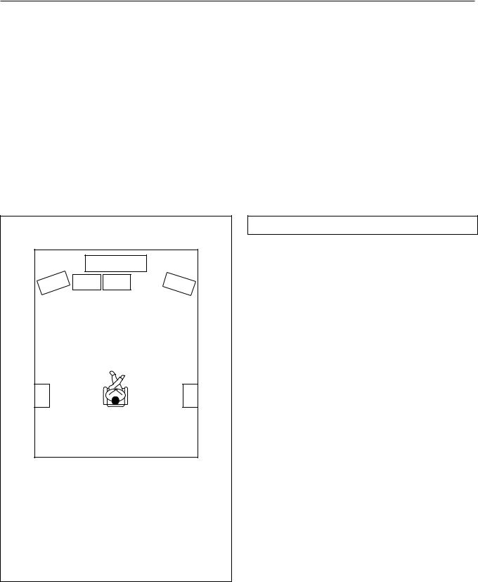
Ideal speaker configuration:
•Right and Left front speakers
•Center speaker
Produces a rich sound image by serving as a sound source for the Right and Left front speakers and enhancing the sonic movement.
• Right and Left surround speakers
Adds three-dimensional sonic movement and produces environmental sound associated with the background and effect sound for each scene.
• Subwoofer
Produces powerful and heavy bass.
|
|
1 |
|
2 |
3 |
4 |
5 |
6 |
|
|
7 |
|
|
8 |
|
1TV or Screen
2Front speaker Left
3Subwoofer
4Center speaker
5Front speaker Right
6Surround speaker Left
7Surround speaker Right
8Listening Position
Minimum speaker configuration for surround sound playback:
•Right and Left front speakers
•Right and Left surround speakers
The sound recorded for the center speaker and the subwoofer will be properly distributed to the Right and Left front speakers and the Right and Left surround speakers for optimized surround playback.
Speaker placement
Ideal speaker placement varies depending on the size of your room and the wall coverings. Here, only typical example of speaker placement and recommendations are shown.
Speaker systems
Left and Right front speakers and Center speaker
•Place these three speakers at the same height from the floor.
•Place each speaker so that sound is aimed at the audience's ears at the listening position.
Left and Right surround speakers
• Place these speakers so that their height is 1 meter higher than that of the audience's ears.
Subwoofer
To get the highest bass effect, place a subwoofer.
You can place your subwoofer anywhere in your room because the placement affects very little the perceived sound.
10
Connecting speakers
• This receiver is designed to produce optimum sound quality when speakers with impedances within the specified ranges are connected. Please check the following information and choose speakers with appropriate impedances for the connections.
FRONT SPEAKERS: |
A or B: 6 ohms min./speaker |
|
|
|
|
||
SURROUND SPEAKERS: |
6 ohms min./speaker |
|
|
|
|
||
CENTER SPEAKER: |
6 ohms min. |
|
|
|
|
||
Connecting the speaker cable |
|
|
|
|
|
• When you use only one |
|
|
|
No! |
|
|
speaker or wish to listen to |
||
1. Twist wire ends very tight. |
|
|
|
monaural (mono) sound, a |
|||
|
|
|
|
single speaker should never |
|||
|
|
|
|
|
|
|
be connected in parallel to |
|
5/8" |
|
|
|
|
|
both the right and left chan- |
|
|
|
|
|
|
|
nel terminals simulta- |
|
|
|
+ – |
– + |
+ – |
– + |
neously. |
|
|
|
R |
L |
R |
L |
|
2. Unscrew. |
3. Insert wire. |
4. Screw. |
|
|
|
|
|
|
|
|
|
|
|
|
No! |
|
|
|
Note: |
|
|
|
|
|
|
|
To prevent damage to circuitry, never short-circuit |
||||
|
|
|
the positive (+) and negative (–) speaker wire. |
||||
Front Speaker A R ch.
Front Speaker A L ch.
SURROUND SPEAKERS FRONT SPEAKERS A
R L R L
Center Speaker
Surround Speaker R ch.
|
|
|
|
|
CENTER |
|
|
|
|
|
|
SPEAKER |
|
R |
|
|
|
|
L |
|
|
|
|
|
|
Use Front SPEAKERS B termi- |
|
|
|
|
|
|
nals to connect a second pair of |
|
|
|
|
|
|
front speakers. |
|
FRONT SPEAKERS B |
|
|
||||
DIGITAL INPUT |
R L |
R L |
V |
S |
SURROUND SPEAKERS |
FRONT SPEAKERS A |
AMP IN |
|
|
|
|
|
|
|
FRONT |
|
|
|
|
OUT |
|
|
|
|
COAXIAL |
|
|
|
|
VIDEO-1 |
ANTENNA |
|
|
|
|
1 |
PRE OUT |
|
|
|
|
|
|
|
||
|
|
|
|
|
|
R |
L |
R |
L |
|
|
FRONT |
|
|
|
|
IN |
|
|
|
|
COAXIAL |
|
|
|
|
|
AM |
|
|
|
|
2 |
SUB |
|
|
|
|
|
|
|
|
|
OPTICAL |
WOOFER |
|
|
|
|
OUT |
|
|
CENTER |
|
|
|
|
|
|
|
|
|
|
||
1 |
CENTER |
|
|
|
VIDEO-2 |
|
|
|
SPEAKER |
|
|
|
|
|
|
|
IN |
|
|
CAUTION: SPEAKER IMPEDANCE |
|
OPTICAL |
SURROUND |
|
|
|
|
FM |
R |
L |
6 OHMS MIN. / SPEAKER |
|
2 |
|
|
|
|
|
75 |
|
|
||
|
FRONT |
|
|
|
VIDEO-3 |
IN |
|
|
|
|
|
|
|
|
|
|
|
|
|
||
OPTICAL |
|
|
|
|
|
|
|
|
|
|
|
SUB |
|
|
|
DVD |
|
|
|
AC OUTLETS |
|
|
WOOFER |
|
|
|
IN |
FRONT SPEAKERS B |
|
AC 120V 60Hz |
|
|
DIGITAL OUTPUT |
|
|
|
|
|
|
||||
|
|
|
|
|
|
AV RECEIVER |
|
|
SWITCHED |
|
|
CENTER |
|
|
|
|
|
|
TOTAL 120W 1A MAX. |
|
|
|
SURROUND |
|
|
(REC) |
MONITOR |
MODEL NO. DTR-7 |
|
|
|
|
|
MULTI CHANNEL |
|
|
|
|
|
|
|
||
|
INPUT |
|
|
OUT |
OUT |
|
|
|
|
|
|
R |
|
L |
TAPE |
|
|
|
|
|
AC INLET |
|
|
|
|
SOURCE |
|
|
|
|
||
|
CD |
|
|
IN |
MULTIOUT |
|
|
|
|
|
|
|
|
|
(PLAY) |
|
|
|
|
|
|
|
GND |
|
|
|
VIDEO |
|
|
|
|
|
|
PHONO |
|
|
|
S VIDEO |
|
|
|
|
|
|
R |
L |
R |
L |
OSD SELECTOR |
|
|
|
|
|
|
|
LOCAL REMOTE |
REMOTE |
|
|
|
||||
CONTROL
DTR-7 / DTR-6
Surround Speaker L ch.
11

Connecting speakers
PRE OUT
FRONT
SUB
WOOFER
CENTER
SURROUND
:Signal flow
DIGITAL INPUT |
R |
L |
R |
L |
V |
S |
SURROUND SPEAKERS |
FRONT SPEAKERS A |
|
AMP IN |
|
|
|
|
|
|
|
|
FRONT |
|
|
|
|
OUT |
|
|
|
|
COAXIAL |
|
|
|
|
VIDEO-1 |
ANTENNA |
|
|
|
|
1 |
PRE OUT |
|
|
|
|
|
|
|
||
|
FRONT |
|
|
|
|
IN |
R |
L |
R |
L |
COAXIAL |
|
|
|
|
|
AM |
|
|
|
|
2 |
SUB |
|
|
|
|
|
|
|
|
|
OPTICAL |
WOOFER |
|
|
|
|
OUT |
|
|
CENTER |
|
|
|
|
|
|
|
|
|
|
||
1 |
CENTER |
|
|
|
VIDEO-2 |
|
|
|
SPEAKER |
|
|
|
|
|
|
|
IN |
|
|
CAUTION: SPEAKER IMPEDANCE |
|
OPTICAL |
SURROUND |
|
|
|
|
FM |
R |
L |
6 OHMS MIN. / SPEAKER |
|
2 |
|
|
|
|
|
|
|
|||
|
|
|
|
|
75 |
|
|
|||
|
FRONT |
|
|
|
VIDEO-3 |
IN |
|
|
|
|
|
|
|
|
|
|
|
|
|
||
OPTICAL |
|
|
|
|
|
|
|
|
|
|
|
SUB |
|
|
|
DVD |
|
|
|
AC OUTLETS |
|
|
WOOFER |
|
|
|
IN |
FRONT SPEAKERS B |
|
AC 120V 60Hz |
|
|
DIGITAL OUTPUT |
|
|
|
|
|
|
||||
|
|
|
|
|
|
AV RECEIVER |
|
|
SWITCHED |
|
|
CENTER |
|
|
|
|
|
|
TOTAL 120W 1A MAX. |
|
|
|
SURROUND |
|
|
(REC) |
MONITOR |
MODEL NO. DTR-7 |
|
|
|
|
|
MULTI CHANNEL |
|
|
|
|
|
|
|
||
|
INPUT |
|
|
OUT |
OUT |
|
|
|
|
|
|
R |
|
L |
TAPE |
|
|
|
|
|
AC INLET |
|
|
|
|
SOURCE |
|
|
|
|
||
|
CD |
|
|
IN |
MULTIOUT |
|
|
|
|
|
|
|
|
|
(PLAY) |
|
|
|
|
|
|
|
GND |
|
|
|
VIDEO |
|
|
|
|
|
|
PHONO |
|
|
|
S VIDEO |
|
|
|
|
|
|
R |
L |
R |
L |
OSD SELECTOR |
|
|
|
|
|
|
|
LOCAL REMOTE |
REMOTE |
|
|
|
||||
|
|
|
|
|
|
|
|
|
||
CONTROL
Connecting a subwoofer
Use the PRE OUT SUBWOOFER jack to connect a subwoofer with a built-in power amplifier. If your subwoofer does not have a builtin amplifier, connect an amplifier to the PRE OUT SUBWOOFER jack and the subwoofer to the amplifier.
Connecting power amplifiers
DTR-7
DIGITAL INPUT |
R |
L |
R |
L |
V |
S |
|
AMP IN |
|
|
|
|
|
|
FRONT |
|
|
|
|
COAXIAL |
|
|
|
|
VIDEO-1 |
1 |
PRE OUT |
|
|
|
|
|
FRONT |
|
|
|
|
COAXIAL |
|
|
|
|
|
2 |
SUB |
|
|
|
|
|
WOOFER |
|
|
|
|
OPTICAL |
|
|
|
|
|
1 |
CENTER |
|
|
|
VIDEO-2 |
OPTICAL |
SURROUND |
|
|
|
|
2 |
|
|
|
|
|
|
FRONT |
|
|
|
VIDEO-3 |
OPTICAL |
|
|
|
|
|
|
SUB |
|
|
|
DVD |
|
WOOFER |
|
|
|
|
DIGITAL OUTPUT |
|
|
|
|
|
|
CENTER |
|
|
|
|
|
SURROUND |
|
|
(REC) |
MONITOR |
|
MULTI CHANNEL |
|
|
||
|
INPUT |
|
|
OUT |
OUT |
|
R |
|
L |
TAPE |
|
|
|
|
|
MULTI SOURCE |
|
|
CD |
|
|
IN |
OUT |
|
|
|
|
(PLAY) |
|
|
GND |
|
|
|
VIDEO |
|
PHONO |
|
|
|
S VIDEO |
|
R |
L |
R |
L |
OSD SELECTOR |
|
|
||||
Notes:
•Keep the jumper plugs so that you will not lose them.
•When the connectors are not in use, replace the jumper plugs.
Connecting power amplifiers
Using auxiliary power amplifiers allows you to listen at louder volumes than with the DTR-7/DTR-6 alone. If power amplifiers are used, connect each speaker to the corresponding power amplifier.
When using speakers connected through external power amplifiers, turn OFF the SPEAKERS A.
DTR-7 / DTR-6
DIGITAL INPUT |
R |
L |
R |
L |
V |
S |
SURROUND SPEAKERS |
FRONT SPEAKERS A |
|
AMP IN |
|
|
|
|
|
|
|
|
FRONT |
|
|
|
|
OUT |
|
|
|
|
COAXIAL |
|
|
|
|
VIDEO-1 |
ANTENNA |
|
|
|
|
1 |
PRE OUT |
|
|
|
|
|
|
|
||
|
|
|
|
|
|
R |
L |
R |
L |
|
|
FRONT |
|
|
|
|
IN |
|
|
|
|
COAXIAL |
|
|
|
|
|
AM |
|
|
|
|
2 |
SUB |
|
|
|
|
|
|
|
|
|
OPTICAL |
WOOFER |
|
|
|
|
OUT |
|
|
CENTER |
|
1 |
CENTER |
|
|
|
VIDEO-2 |
|
|
|
SPEAKER |
|
|
|
|
|
|
|
IN |
|
|
CAUTION: SPEAKER IMPEDANCE |
|
OPTICAL |
SURROUND |
|
|
|
|
FM |
R |
L |
6 OHMS MIN. / SPEAKER |
|
2 |
|
|
|
|
|
75 |
|
|
||
|
FRONT |
|
|
|
VIDEO-3 |
IN |
|
|
|
|
|
|
|
|
|
|
|
|
|
||
OPTICAL |
|
|
|
|
|
|
|
|
|
|
|
SUB |
|
|
|
DVD |
|
|
|
AC OUTLETS |
|
|
WOOFER |
|
|
|
IN |
FRONT SPEAKERS B |
|
AC 120V 60Hz |
|
|
DIGITAL OUTPUT |
|
|
|
|
|
|
||||
|
|
|
|
|
|
AV RECEIVER |
|
|
SWITCHED |
|
|
CENTER |
|
|
|
|
|
|
TOTAL 120W 1A MAX. |
|
|
|
SURROUND |
|
|
(REC) |
MONITOR |
MODEL NO. DTR-7 |
|
|
|
|
|
MULTI CHANNEL |
|
|
|
|
|
|
|
||
|
INPUT |
|
|
OUT |
OUT |
|
|
|
|
|
|
R |
|
L |
TAPE |
|
|
|
|
|
AC INLET |
|
|
|
|
SOURCE |
|
|
|
|
||
|
CD |
|
|
IN |
MULTIOUT |
|
|
|
|
|
|
|
|
|
(PLAY) |
|
|
|
|
|
|
|
GND |
|
|
|
VIDEO |
|
|
|
|
|
|
PHONO |
|
|
|
S VIDEO |
|
|
|
|
|
|
R |
L |
R |
L |
OSD SELECTOR |
|
|
|
|
|
|
|
LOCAL REMOTE |
REMOTE |
|
|
|
||||
|
|
|
|
|
|
|
|
|
||
CONTROL
R L
PRE OUT
FRONT
SUB
WOOFER
CENTER
SURROUND
Right front Speaker
Left front Speaker
Subwoofer
Center Speaker
Left Surround Speaker
Right Surround Speaker
12

Connecting an equalizer (DTR-7)
DTR-7
DIGITAL INPUT |
R |
L |
R |
L |
V |
S |
SURROUND SPEAKERS |
FRONT SPEAKERS A |
|
AMP IN |
|
|
|
|
|
|
|
|
FRONT |
|
|
|
|
OUT |
|
|
|
|
COAXIAL |
|
|
|
|
VIDEO-1 |
ANTENNA |
|
|
|
|
1 |
PRE OUT |
|
|
|
|
|
|
|
||
|
|
|
|
|
|
R |
L |
R |
L |
|
|
FRONT |
|
|
|
|
IN |
|
|
|
|
COAXIAL |
|
|
|
|
|
AM |
|
|
|
|
2 |
SUB |
|
|
|
|
|
|
|
|
|
OPTICAL |
WOOFER |
|
|
|
|
OUT |
|
|
CENTER |
|
1 |
CENTER |
|
|
|
VIDEO-2 |
|
|
|
SPEAKER |
|
|
|
|
|
|
|
IN |
|
|
CAUTION: SPEAKER IMPEDANCE |
|
OPTICAL |
SURROUND |
|
|
|
|
FM |
R |
L |
6 OHMS MIN. / SPEAKER |
|
2 |
|
|
|
|
|
75 |
|
|
||
|
FRONT |
|
|
|
VIDEO-3 |
IN |
|
|
|
|
|
|
|
|
|
|
|
|
|
||
OPTICAL |
|
|
|
|
|
|
|
|
|
|
|
SUB |
|
|
|
DVD |
|
|
|
AC OUTLETS |
|
|
WOOFER |
|
|
|
IN |
FRONT SPEAKERS B |
|
AC 120V 60Hz |
|
|
DIGITAL OUTPUT |
|
|
|
|
|
|
||||
|
|
|
|
|
|
AV RECEIVER |
|
|
SWITCHED |
|
|
CENTER |
|
|
|
|
|
|
TOTAL 120W 1A MAX. |
|
|
|
SURROUND |
|
|
(REC) |
MONITOR |
MODEL NO. DTR-7 |
|
|
|
|
|
MULTI CHANNEL |
|
|
|
|
|
|
|
||
|
INPUT |
|
|
OUT |
OUT |
|
|
|
|
|
|
R |
|
L |
TAPE |
|
|
|
|
|
AC INLET |
|
|
|
|
SOURCE |
|
|
|
|
||
|
CD |
|
|
IN |
MULTIOUT |
|
|
|
|
|
|
|
|
|
(PLAY) |
|
|
|
|
|
|
|
GND |
|
|
|
VIDEO |
|
|
|
|
|
|
PHONO |
|
|
|
S VIDEO |
|
|
|
|
|
|
R |
L |
R |
L |
OSD SELECTOR |
|
|
|
|
|
|
|
LOCAL REMOTE |
REMOTE |
|
|
|
||||
|
|
|
|
|
|
|
CONTROL |
|
|
|
|
|
|
R |
|
L |
|
|
|
|
|
AMP IN |
|
|
|
|
|
Output jack |
|
|||
|
FRONT |
|
|
|
|
|
|
|
|
|
PRE OUT |
|
|
|
|
|
Input jack |
|
|||
|
FRONT |
|
|
|
|
|
|
|
|
|
Input jack
Epualizer
The AMP IN and the PRE OUT FRONT connectors are attached with jumper plugs. When connecting an equalizer, remove these jumper plugs before connecting the audio connection cables.
1. Remove the jumper plugs.
See “Connecting power amplifiers.”
2. Connect an equalizer.
Connecting the power
DIGITAL INPUT |
R |
L |
R |
L |
V |
S |
SURROUND SPEAKERS |
FRONT SPEAKERS A |
|
AMP IN |
|
|
|
|
|
|
|
|
FRONT |
|
|
|
|
OUT |
|
|
|
|
|
COAXIAL |
|
|
|
|
VIDEO-1 |
ANTENNA |
|
|
|
|
|
1 |
PRE OUT |
|
|
|
|
R |
L |
R |
L |
|
|
|
FRONT |
|
|
|
|
IN |
|
||||
COAXIAL |
|
|
|
|
|
|
|
|
|
|
|
2 |
SUB |
|
|
|
|
|
|
|
|
|
|
OPTICAL |
WOOFER |
|
|
|
|
OUT |
|
|
CENTER |
|
|
1 |
CENTER |
|
|
|
VIDEO-2 |
|
|
|
SPEAKER |
|
|
|
|
|
|
|
|
IN |
|
|
CAUTION: SPEAKER IMPEDANCE |
|
|
OPTICAL |
SURROUND |
|
|
|
|
|
R |
L |
6 OHMS MIN. / SPEAKER |
|
|
2 |
|
|
|
|
|
|
|
|
|
||
|
FRONT |
|
|
|
VIDEO-3 |
IN |
|
|
|
|
|
|
|
|
|
|
|
|
|
|
|
||
OPTICAL |
|
|
|
|
|
|
|
|
|
|
|
|
SUB |
|
|
|
DVD |
|
FRONT SPEAKERS B |
|
AC OUTLETS |
|
|
|
WOOFER |
|
|
|
|
|
|
AC 120V 60Hz |
|
|
|
DIGITAL OUTPUT |
|
|
|
|
IN |
|
|
SWITCHED |
|
|
|
|
CENTER |
|
|
|
|
AV RECEIVER |
|
|
TOTAL 120W 1A MAX. |
|
|
|
SURROUND |
|
|
(REC) |
MONITOR |
MODEL NO. DTR-7 |
|
|
|
|
|
|
MULTI CHANNEL |
|
|
|
|
|
|
|
|
||
|
INPUT |
|
|
OUT |
OUT |
|
|
|
|
|
|
|
R |
|
L |
TAPE |
|
|
|
|
|
AC INLET |
1 |
|
|
|
|
|
|
|
|
|
|||
|
CD |
|
|
IN |
|
|
|
|
|
|
|
|
|
|
(PLAY) |
|
|
|
|
|
|
||
|
GND |
|
|
|
VIDEO |
|
|
|
|
|
|
|
PHONO |
|
|
|
S VIDEO |
|
|
|
|
|
|
|
R |
L |
R |
L |
OSD SELECTOR |
|
|
|
|
|
|
|
|
LOCAL REMOTE |
REMOTE |
|
|
|
|
||||
|
|
|
|
|
|
|
CONTROL |
|
|
|
|
2
2.STANDBY/ON button STANDBY indicator
1 POWER switch
Display
|
|
|
|
|
FM MUTE/ |
|
|
CHARACTER/ |
SP/SYS |
AUDIO |
BASS/ |
|
|
MASTER VOLUME |
||
|
DIMMER |
|
|
|
MODE |
DOWN |
TUNING |
UP |
MEMORY |
SETUP |
ADJUSTMENT |
TREBLE |
|
|
|
|
STANDBY/ON |
|
|
|
|
|
|
|
|
|
|
|
|
|
|
|
|
|
|
|
|
|
|
|
|
|
|
MODE |
|
W |
N |
|
|
|
|
|
|
|
|
|
|
|
|
|
|
|
D O |
|
|
U |
|
|
|
|
|
|
|
|
|
|
|
PRESET/MODE ADJ |
|
|
|
P |
||
STANDBY MULTI SOURCE |
|
|
|
|
|
|
|
|
|
|
|
|
|
|
|
|
POWER |
|
|
|
|
|
|
|
|
|
|
|
|
|
|
|
|
ON OFF |
|
|
|
|
|
|
|
|
|
PUSH TO ENTER |
|
|
|
|
|
|
A SPEAKERS B |
|
|
|
|
LISTENING MODE |
|
|
|
REC OUT/ |
DIGITAL/ |
|
|
|
|
|
|
DISPLAY |
|
|
DIRECT |
STEREO |
/DTS |
THX |
|
DSP |
MULTI SOURCE |
ANALOG |
CH LEVEL |
|
|
|
|
|
|
|
|
|
|
|
SURROUND |
|
|
|
MODE |
|
|
|
|
|
|
PHONES |
MULTI CH INPUT |
|
|
|
|
|
|
|
|
|
|
|
|
|
|
VIDEO4 (MONO) |
|
|
|
|
|
|
|
|
|
|
|
|
|
|
|
||
|
DVD |
VIDEO-1 |
VIDEO-2 |
VIDEO-3 |
VIDEO-4 |
TAPE |
FM |
AM |
PHONO |
C D |
|
|
|
|
||
|
|
|
|
|
|
|
|
|
|
|
|
|
S VIDEO |
VIDEO |
L AUDIO R |
|
DTR-7 by 


2.POWER STNBY button
2.POWER ON button
1.MODE AUDIO button
Connecting a power cable
1.Connect the outlet plug on the included power cable to the AC INLET on the DTR-7/ DTR-6.
2.Plug-in the other end of the cable to a wall AC outlet.
Notes:
•Do not use any power cable other than the included cable. The included cable is designed for use only with the DTR-7/ DTR-6. Do not use it for any other device.
•Do not connect or disconnect the outlet plug from the DTR-7/DTR-6 while the other end is plugged into the wall AC outlet.
Connecting the power
•Before you turn on the receiver, confirm that all connections have been made properly.
•Turning on this receiver’s power may cause a momentary power surge, which might interfere with other electrical equipment, such as computers. If this happens, use a wall outlet on a different circuit.
1.Press the POWER switch to set the receiver to Standby mode.
The STANDBY indicator will light up.
2.Press the STANDBY/ON button to turn on the receiver. The display will light up and the STANDBY indicator will be turned off.
If you press the STANDBY/ON button, the receiver returns to Standby mode.
Turning the power on from the remote controller:
1.Press the MODE AUDIO button.
2.Press the POWER ON button to turn on the power to the receiver, or press the POWER STNBY button to set the receiver in standby mode.
•You cannot use the remote controller if the POWER switch on the receiver is set to OFF.
•Set the volume level to minimum before you turn off the power to the receiver.
13
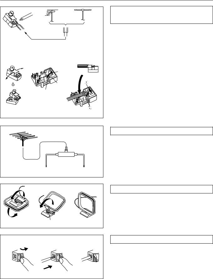
Making antenna connections
|
Outdoor |
Indoor |
||||
|
antenna |
antenna |
||||
|
|
300 ohms |
|
|
|
|
|
|
ribbon wire |
|
|
|
|
1 |
2 |
3 |
|
|
|
|
|
|
|
|
|
|
|
|
|
|
|
|||
|
|
|
|
|
|
|
|
|
|
|
|||
|
|
|
|
|
|
|
|
|
|
|
6 |
3 |
6 |
|
Slit B |
|
mm mm mm |
|||
|
|
|
15mm |
|||
|
|
|
|
|||
|
Wire A |
|
|
|
|
|
|
Slit C |
|
|
|
|
|
Connecting the antenna cable to the 75/300 ohm antenna adapter. (The antenna adapter must be separately ordered.)
Connecting the 300 ohm ribbon wire:
Loosen the screws and wrap the wire around these screws. Then tighten the screws with a screwdriver.
Connecting the coaxial cable:
1.With your fingernail or a small screwdriver, press the stoppers outward and remove the cover.
2.Remove the transformer wire A from slit B and insert it into slit C.
3.Prepare the coaxial cable as shown in the diagram.
Connect the 75/300 ohm antenna adapter to the coaxial cable. 1 Insert the end of the cable.
2 Clamp it in place with pliers.
4.Re-install the cover.
Directional linkage type splitter
To receiver |
To TV (or VCR) |
Directional Iinkage
Do not use the same antenna for both FM and TV (or VCR) reception since the FM and TV (or VCR) signals can interfere with each other. If you must use a common FM/TV (or VCR) antenna, use a directional linkage type splitter.
Insert into the hole.
Assembling the AM loop antenna
Assemble the loop antenna as shown in the illustration.
• Refer to the next page for details on connecting the AM loop antenna.
|
|
|
Connecting the antenna cable |
|
1 |
2 |
3 |
1. |
Press down the lever. |
|
|
|
2. |
Insert the wire into the hole. |
|
|
|
3. |
Release the lever to replace it. |
14
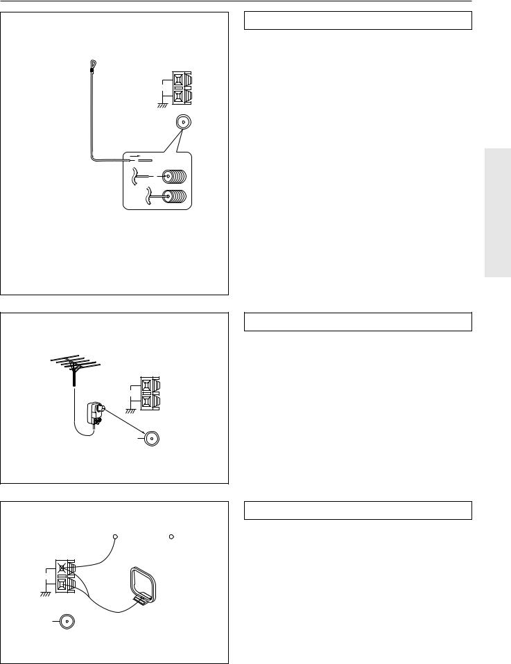
Making antenna connections
ANTENNA |
AM |
FM 75
Remove the insulation at the end of the cable, then fully insert the stripped end of the cable.
ANTENNA
AM
FM 75
|
|
|
|
|
|
|
|
|
|
|
|
|
|
Outdoor |
|
ANTENNA |
|
|
antenna |
|
|||
|
|
|
|
|
|
|
|
|
|
|
|
|
|
|
|
|
|
|
|
|
|
|
|
AM
FM 75
Connecting the included antennas
Connecting the FM indoor antenna:
The FM indoor antenna is for indoor use only. Extend the antenna and move it in various directions until the clearest signal is received. Fix it with push pins or similar implements in the position that will cause the least amount of distortion.
If the reception is not very clear with the attached FM indoor antenna, the use of an outdoor antenna is recommended.
Connecting the AM loop antenna:
The AM loop antenna is for indoor use only. Set it in the direction and position where you receive the clearest sound. Put it as far away as possible from the unit, TVs, speaker cables, and power cords.
When reception is not satisfactory with the attached AM loop antenna alone, connection of an outdoor antenna is recommended.
Connecting an FM outdoor antenna
Please make sure that you follow the considerations below regarding the location.
Keep the antenna away from noise sources (neon signs, busy roads, etc.).
It is dangerous to put the antenna close to power lines. Keep it well away from power lines, transformers, etc.
• To avoid the risk of lightning and electrical shock, grounding is necessary. Follow item 19 of the “Important Safeguards” on page 2 when you install the outdoor antenna.
Connecting an AM outdoor antenna
The outdoor antenna will be more effective if it is stretched horizontally above a window or outside.
•Do not remove the AM loop antenna.
•To avoid the risk of lightning and electrical shock, grounding is necessary. Follow item 19 of the “Important Safeguards” on page 2 when you install the outdoor antenna.
15
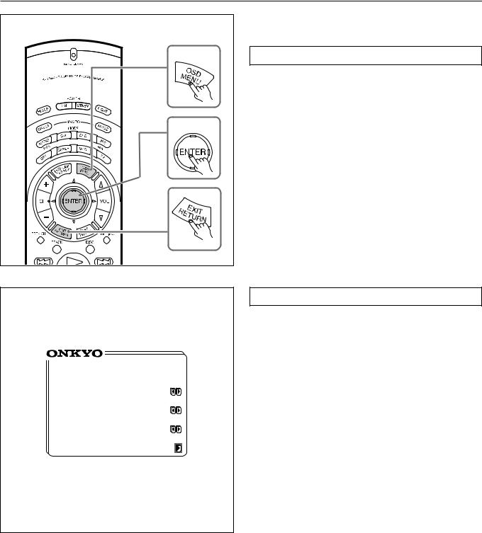
Using the on-screen display
|
1 |
|
2~4 |
3 |
|
** |
Screen Setup ** |
Background
Color = Green 1
Superimpose
Mode = Normal
Immediate
Display = ON
Character Position
Using the OSD (on-screen display) function lets you display each screen on your TV so that you can perform various settings using only the remote controller.
How to use the on-screen display
1.Press the OSD MENU button.
The on-screen display appears.
2.Press the upper or lower edge of the ENTER/Cursor button to select the item.
The items you can select on each screen are shown on the next page.
3.Press the right edge of the ENTER/Cursor button to display the setting screen.
On each screen, you can press the upper or lower edge of the ENTER/Cursor button to select an item and then press the right or left edge of the button to change the setting.
If the item has an additional screen, you can press the right edge of the button to change to that screen.
4.Press the center of the ENTER/Cursor button.
Use either of the following methods to turn off the on-screen display.
• Press the center of the ENTER/Cursor button.
By pressing this button, you can follow in reverse the sequence in which you have displayed each setting screen. Finally, the onscreen display disappears.
• Press the EXIT button.
The on-screen display disappears immediately.
Screen Setup
Use the on-screen display to set the background color, the superimpose mode, etc.
1.Press the OSD MENU button.
2.Select “Screen Setup” and press the right edge of the ENTER/Cursor button.
3.Press the upper or lower edge of the ENTER/Cursor button to select each item and then press the right or left edge of the button to set a parameter.
Background Color : Select the desired color from BLUE-1, BLUE-2, GREEN-1, GREEN-2, MAGENTA, RED-1, and RED-2.
Superimpose Mode : Select one of the following:
OFF : The on-screen display appears on the selected background color.
Normal : The on-screen display is superimposed on images when video signals are input and shown on the selected background color when no video signal is input.
Black : The on-screen display appears on black screen. Immediate Display : Select either “ON” or “OFF.” When set to “ON,”
the screen will show for 3 seconds the result (or process) of the operation every time you operate the unit. For example, the volume level indicator appears on the screen when you increase the sound volume.
Character Position : Using the ENTER/Cursor button, move the onscreen display to the lower left, upper left, upper right, or lower
right of the TV screen.
4.Press the center of the ENTER/Cursor button, or press the EXIT button.
16
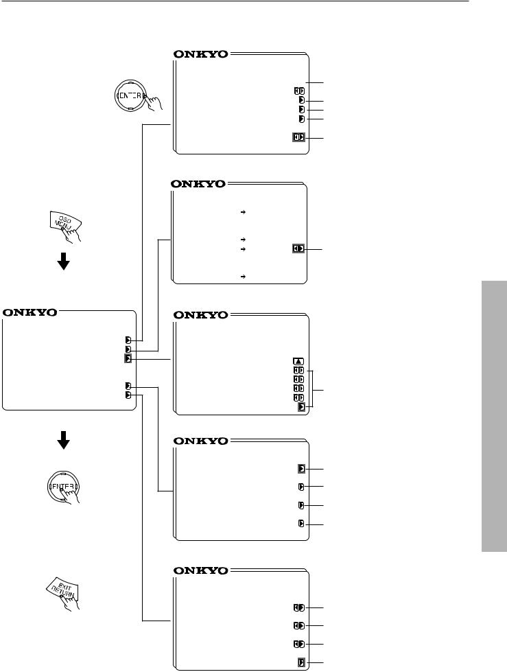
Using the on-screen display
OSD screens
Input Selector screen (page 27,32)
|
** |
Input Selector ** |
|
||||
|
Input |
= DVD |
|
Select the input source (page 27). |
|||
|
|
|
OPTICAL 1 |
Perform digital input setting (page 29). |
|||
|
Digital Input Setup |
||||||
|
Video Assign Setup |
Assign a video input source (page 40). |
|||||
|
IntelliVolume Setup |
Perform IntelliVolume setting (page 43). |
|||||
|
Listening Dolby |
|
|
||||
|
|
Mode= Pro Logic |
Set the listening mode (page 36). |
||||
|
|
|
THX Cinema |
|
|||
|
Rec Selector screen (page 45) |
|
|||||
|
** |
Rec Selector ** |
|
||||
|
•Picture |
VIDEO |
|
||||
|
=DVD |
|
|
1,2 |
|
|
|
|
•Sound |
TAPE |
|
|
|||
|
=DVD |
|
VIDEO |
Select the audio recording source (page 45). |
|||
|
|
|
|
1,2 |
|
|
|
|
•Digital |
OPTICAL |
|
||||
|
=---- |
|
OUT |
|
|
||
|
Listening Mode Setup screen (page 38) |
|
|||||
*** Menu *** |
** Listening Mode ** |
|
|||||
Input Selector |
Listening |
|
Setup |
|
|||
|
|
|
|
||||
Rec Selector |
|
|
|
|
|||
|
Mode=Mono Movie |
|
|||||
Listening Mode Setup |
|
|
|||||
|
|
|
|
|
|
||
|
Front Effect |
= ON |
|
||||
Speaker Setup |
Reflect Level |
= |
0dB |
|
|||
Reverb Level |
= |
0dB |
Set the listening mode parameters |
||||
Screen Setup |
|||||||
Room Size |
|
=Mid |
(pages 38,39). |
||||
|
|
||||||
|
|
Default |
|
|
|
||
|
Speaker Setup screen (page 19) |
|
|||||
|
** |
Speaker Setup ** |
|
||||
|
Config Setup |
|
|
Set the speaker configuration (page 19). |
|||
|
Distance Setup |
|
Set the speaker distance (page 20). |
||||
|
Level Setup |
|
|
Set the speaker output level (page 21). |
|||
|
Bass Peak Setup |
|
Set the bass peak level (page 23). |
||||
or |
|
|
|
|
|
|
|
|
Screen Setup screen (See the previous page.) |
||||||
|
** |
Screen Setup ** |
|
||||
|
Background |
|
|
Set the background color. |
|||
|
Color |
= Green 1 |
|||||
|
Superimpose |
|
|
Set the superimpose mode. |
|||
|
|
Mode |
= Normal |
||||
|
Immediate |
|
|
|
|
||
|
Display |
= ON |
|
Set the simultaneous display mode. |
|||
|
Character Position |
Set the display position of characters. |
|||||
17

Setting the speaker configuration
Perform this setup before using the unit.
SP/SYS SETUP button |
SMART SCAN CONTROLLER |
|
FM MUTE/ |
|
|
CHARACTER/ |
SP/SYS |
AUDIO |
BASS/ |
DIMMER |
MODE |
DOWN TUNING |
UP |
MEMORY |
SETUP |
ADJUSTMENT |
TREBLE |
STANDBY/ON
MODE
PRESET/MODE ADJ
STANDBY MULTI SOURCE |
|
|
|
|
|
|
|
SMART SCAN |
|
|
|
STAND-BY |
|
|
|
|
|
|
|
CONTROLLER |
|
|
|
POWER |
|
|
|
|
|
|
|
|
|
|
|
|
|
|
|
|
|
|
|
|
PUSH TO ENTER |
|
|
ON OFF |
|
|
|
|
|
|
|
|
|
|
|
|
|
|
|
|
|
LISTENING MODE |
|
|
REC OUT/ |
DIGITAL/ |
|
A SPEAKERS B |
|
|
|
|
|
|
|
|
|
||
DISPLAY |
|
|
DIRECT |
STEREO |
/DTS |
THX |
DSP |
MULTIRECSOURCET |
ANALOG |
CH LEVEL |
|
|
|
|
|
|
|
SURROUND |
|
|
MODE |
|
|
PHONES |
MULTI CH INPUT |
|
|
|
|
|
|
|
|
|
|
|
DVD |
VIDEO-1 |
VIDEO-2 |
VIDEO-3 |
VIDEO-4 |
TAPE |
|
FM |
AM |
PHONO |
C D |
|
|
|
MASTER VOLUME |
|
|
W |
N |
D |
O |
U |
|
|
P |
||
|
|
|
VIDEO4 (MONO)
S VIDEO |
VIDEO |
L AUDIO R |
DTR-7 by 


1 |
SP/SYS |
|
|
|
|
|
|
|
Setting the speaker configuration parameters |
|
SETUP |
|
SPEAKERS |
|
|
TUNED |
|
|
|
|
|
|
|
|
|
|
|
|
||||
|
|
|
A |
|
AUTO |
|
|
Using the SMART SCAN CONTROLLER, you can easily set the |
||
|
|
|
|
|
|
|
|
|
||
|
|
|
|
|
|
|
|
|
speaker configuration. Turn it to select the parameter and press it to |
|
|
|
|
|
|
|
|
|
|
go to the next item. |
|
|
|
|
|
|
|
|
|
|
1. Press the SP/SYS SETUP button. |
|
|
PRESET/MODE ADJ |
|
|
|
|
|
|
|
“Config Setup?” appears. Then Press the SMART SCAN CON- |
|
|
|
|
|
|
|
|
|
|
TROLLER. |
|
|
|
|
|
|
|
|
|
|
2. For the DTR-6, go to the next step. |
|
|
|
|
|
|
|
|
|
|
For the DTR-7, “All Ch For THX” appears. |
|
|
PUSH TO ENTER |
|
|
|
|
|
|
|
Set “Yes” or “No.” |
|
|
|
|
|
|
|
|
|
|
Yes: |
Your system is a THX speaker system. |
|
|
|
|
|
|
|
|
|||
2 |
|
|
|
|
|
|
|
|
|
(The following steps are unnecessary.) |
PRESET/MODE ADJ |
DTR-7 only |
|
|
|
No : Your system is a non-THX speaker system. |
|||||
|
|
|
|
Press the SMART SCAN CONTROLLER. |
||||||
|
|
|
|
|
|
|
|
|
||
|
|
|
SPEAKERS |
|
|
TUNED |
|
|
3. Set whether or not a subwoofer is connected. |
|
|
|
|
A |
|
AUTO |
|
|
|
|
|
|
|
|
|
|
|
|
|
|
Yes: |
A subwoofer is connected. |
|
|
|
|
|
|
|
|
|
No: |
A subwoofer is NOT connected. |
|
|
|
|
|
|
|
|
|||
|
PUSH TO ENTER |
|
|
|
|
|
|
|
Press the SMART SCAN CONTROLLER. |
|
|
|
|
|
|
|
|
|
|
4. Select the size of your front speakers. |
|
|
PRESET/MODE ADJ |
|
|
|
|
|
|
|
Large: Large front speakers are used. |
|
|
|
|
|
|
|
|
|
|
Small: Small front speakers are used. |
|
|
|
|
|
|
|
|
|
|
Press the SMART SCAN CONTROLLER. |
|
|
|
|
|
|
|
|
|
|
5. Select the size of your center speaker. |
|
|
|
|
|
|
|
|
|
|
Large: A large center speaker is used. |
|
|
PUSH TO ENTER |
|
|
|
|
|
|
|
Small: A small center speaker is used. |
|
|
|
|
|
|
|
|
|
|
||
|
|
|
|
|
|
|
|
|
None: A center speaker is NOT used. |
|
3 ~ 6 |
|
|
|
|
|
|
||||
|
|
|
|
|
|
|
Press the SMART SCAN CONTROLLER. |
|||
|
|
|
|
|
|
|
6. Select the size of your surround speakers. |
|||
|
PRESET/MODE ADJ |
|
|
|
|
|
|
|
||
|
|
|
|
|
|
|
|
Large: Large surround speakers are used. |
||
|
|
|
|
|
|
|
|
|
||
|
|
|
A |
|
|
FM STEREO AUTO |
|
|
Small: Small surround speakers are used. |
|
|
|
|
SPEAKERS |
|
|
TUNED |
|
|
|
|
|
|
|
|
|
|
|
|
|
None: Surround speakers are NOT used. |
|
|
|
|
|
|
|
|
|
|||
|
|
|
|
|
|
|
|
|
7. Press the SMART SCAN CONTROLLER. |
|
|
|
|
|
|
|
|
|
|||
|
PUSH TO ENTER |
|
|
|
|
|
|
|
This completes the speaker configuration setup. |
|
Front
PRESET/MODE ADJ
Center
Surround
PUSH TO ENTER
7 |
PRESET/MODE ADJ |
PUSH TO ENTER
18
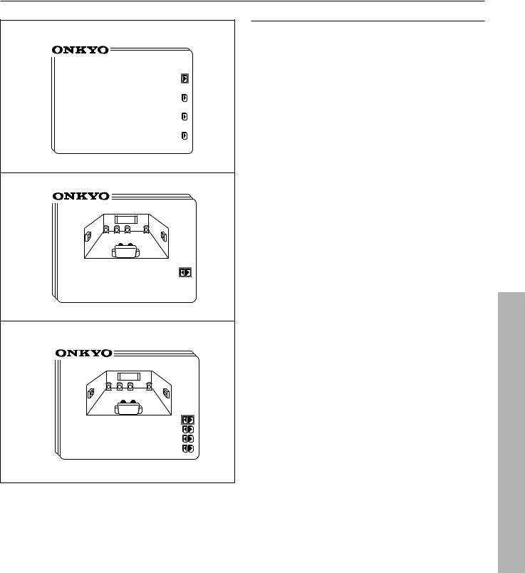
Setting the speaker configuration
3
** Speaker Setup **
Config Setup
Distance Setup
Level Setup
Bass Peak Setup
4
* Config Setup *
All Channel For
THX Speakers =No
5
* Config Setup *
Subwoofer =Yes
Front =Small
Center =Small
Surround =Small
•Using the on-screen display
1.Press the OSD MENU button.
2.Select “Speaker Setup” and then press the right edge of the ENTER/Cursor button.
3.Select “Config Setup” and then press the right edge of the ENTER/Cursor button.
4.For the DTR-6, go to the next step.
For the DTR-7, the display shows “All Channel For THX Speakers.”
Select “Yes” and then press the center of the ENTER/Cursor button. This sets all the connected speakers to THX speakers.(The following steps are unnecessary.)
Select “No” and then press the center of the ENTER/Cursor button to go to the next step.
5.Press the upper or lower edge of the ENTER/Cursor button to set each item and then press the right or left edge of the button to set a parameter
Subwoofer: Set whether or not a subwoofer is connected.
Yes: |
A subwoofer is connected. |
No: |
A subwoofer is NOT connected. |
Front : Select the size of your front speakers.
Large: Large front speakers are used. Small: Small front speakers are used.
Center : Select the size of your center speaker.
Large: A large center speaker is used. Small: A small center speaker is used. None: A center speaker is NOT used.
Surround : Select the size of your surround speakers.
Large: Large surround speakers are used. Small: Small surround speakers are used. None: Surround speakers are NOT used.
6.Press the center of the ENTER/Cursor button, or press the EXIT button, to exit the setup mode.
19
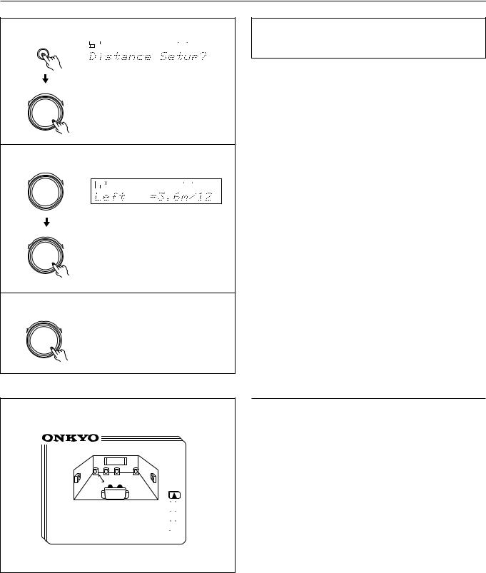
Setting the speaker distance
1
SP/SYS |
|
|
|
|
|
SETUP |
|
SPEAKERS |
|
|
TUNED |
|
A |
|
|
AUTO |
|
|
|
|
|
|
|
PRESET/MODE ADJ
PUSH TO ENTER
2 ~ 7
PRESET/MODE ADJ
SPEAKERS |
|
|
TUNED |
|
|
|
|
|
|
A |
|
|
PCM DIGITAL |
FM STEREO AUTO |
ft
PUSH TO ENTER
PRESET/MODE ADJ
PUSH TO ENTER
8
PRESET/MODE ADJ
PUSH TO ENTER
Setting the distance from each speaker to the listening position
(Loudspeaker Position Time Synchronization*)
Select a value that is closest to the actual distance between each speaker and the listening position.
Using the SMART SCAN CONTROLLER, you can easily set the speaker configuration. Turn it to select the setting and press it to go to the next item.
For each speaker, you can set a distance of 0.3 meter to 9.0 meters (or 1 foot to 30 feet) in increments of 30 cm (1 foot).
1.Press the SP/SYS SETUP button repeatedly until “Distance Setup ?” appears.
Press the SMART SCAN CONTROLLER.
2.“Left=” appears. Set the distance from the left front speaker.
Press the SMART SCAN CONTROLLER.
3.“Center=” appears. Set the distance from the center speaker.
Press the SMART SCAN CONTROLLER.
4.“Right=” appears. Set the distance from the Right front speaker.
Press the SMART SCAN CONTROLLER.
5.“R-Sur=” appears. Set the distance from the Right surround speaker.
Press the SMART SCAN CONTROLLER.
6.“L-Sur=” appears Set the distance from the left surround speaker.
Press the SMART SCAN CONTROLLER.
7.“SW=” appears. Set the distance from the subwoofer.
8.Press the SMART SCAN CONTROLLER.
The speaker distance setup has been completed.
*Loudspeaker Position Time Synchronization is a registered trademark of Lucasfilm LTD.
* Distance Setup *
Left =3.6m/12ft  Center =3.6m/12ft
 Right =3.6m/12ft
 (R-Sur =2.1m/ 7ft)
•Using the on-screen display
1.Press the OSD MENU button.
2.Select “Speaker Setup” and then press the right edge of the ENTER/Cursor button.
3.Select “Distance Setup” and then press the right edge of the ENTER/Cursor button.
You can now set the distance from each speaker.
(When the cursor is on “Right,” you can press the lower edge of the ENTER/Cursor button to display additional items.)
Select a value that is closest to the actual distance. For each speaker, you can set a distance of 0.3 meter to 9.0 meters (or 1 foot to 30 feet) in increments of 30 cm (1 foot).
Left: Left front speaker Center: Center speaker Right: Right front speaker
R-Sur: Right surround speaker L-Sur: Left surround speaker
Subwoofer: Subwoofer
4.Press the center of the ENTER/Cursor button, or press the EXIT button, to exit the setup mode.
20
 Loading...