


DRX-2.1

Before Start ...........................................................................................2
What's in the box.....................................................................................2
Part Names ...........................................................................................3
Part Names .............................................................................................3
Install .....................................................................................................7
Installation procedure..............................................................................7
Step1: Speaker Layout ............................................................................8
Step2: Connect the Speakers................................................................14
Step3: Connect the TV & AV Components............................................16
Initial Setup .........................................................................................22
Initial Setup with Auto Start-up Wizard..................................................22
Playback ..............................................................................................24
AV Component Playback.......................................................................24
BLUETOOTH
®
Playback.......................................................................24
Network Functions.................................................................................25
USB Storage Device .............................................................................26
Listening to the AM/FM Radio...............................................................27
Multi-zone..............................................................................................29
Listening Mode......................................................................................30
DRX-2.1
En
AV Receiver
Basic Manual
For details about the Network Functions and listening modes,
and information regarding the advanced settings, refer to the
"Advanced Manual" available on our website.
http://integraworldwide.com/manual/drx21/adv/en.html
2
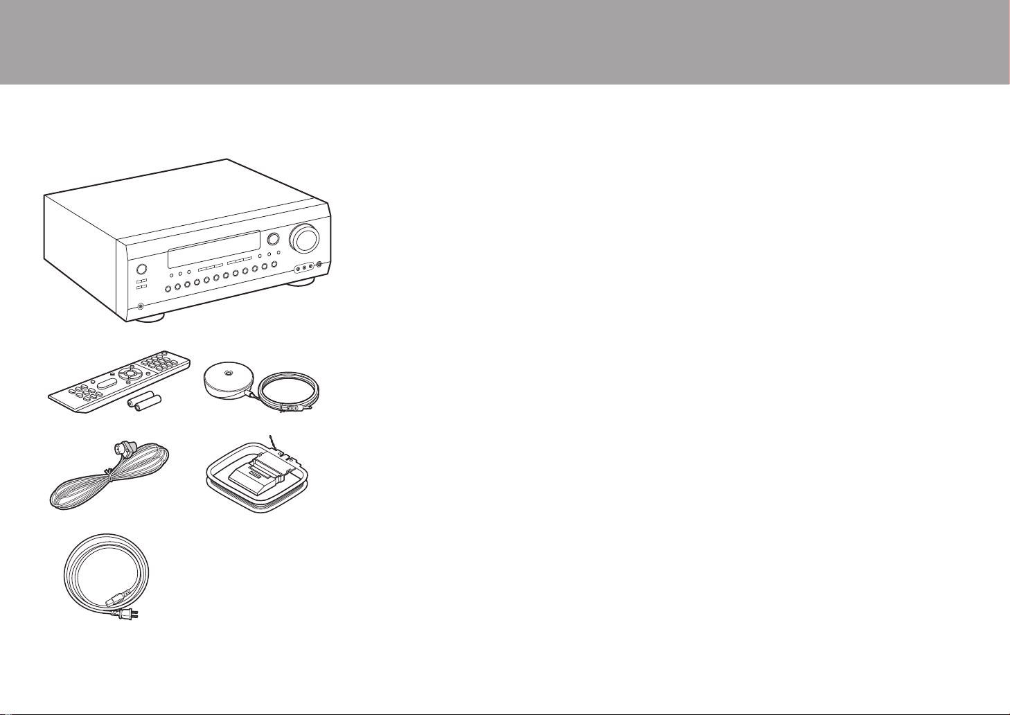
What's in the box
1. Main unit (1)
2. Remote controller (RC-912R) (1), Batteries (AAA/R03)
(2)
3. Speaker setup microphone (1)
0 Used during Initial Setup.
4. Indoor FM antenna (1)
5. AM loop antenna (1)
6. Power cord (1)
0 Quick Start Guide (1)
0 Basic Manual (This manual)
0 Connect speakers with 4 Ω to 16 Ω impedance.
0 The power cord must be connected only after all other
cable connections are completed.
0 We will not accept responsibility for damage arising from
the connection of equipment manufactured by other
companies.
0 Functionality may be introduced by firmware updates
and service providers may cease services, meaning that
some network services and content may become
unavailable in the future. Furthermore, available services
may vary depending on your area of residence.
0 Details on the firmware update will be posted on our
website, etc.
0 Specifications and appearance are subject to change
without prior notice.
> Before Start > Part Names > Install > Initial Setup > Playback
1
32
54
6
3
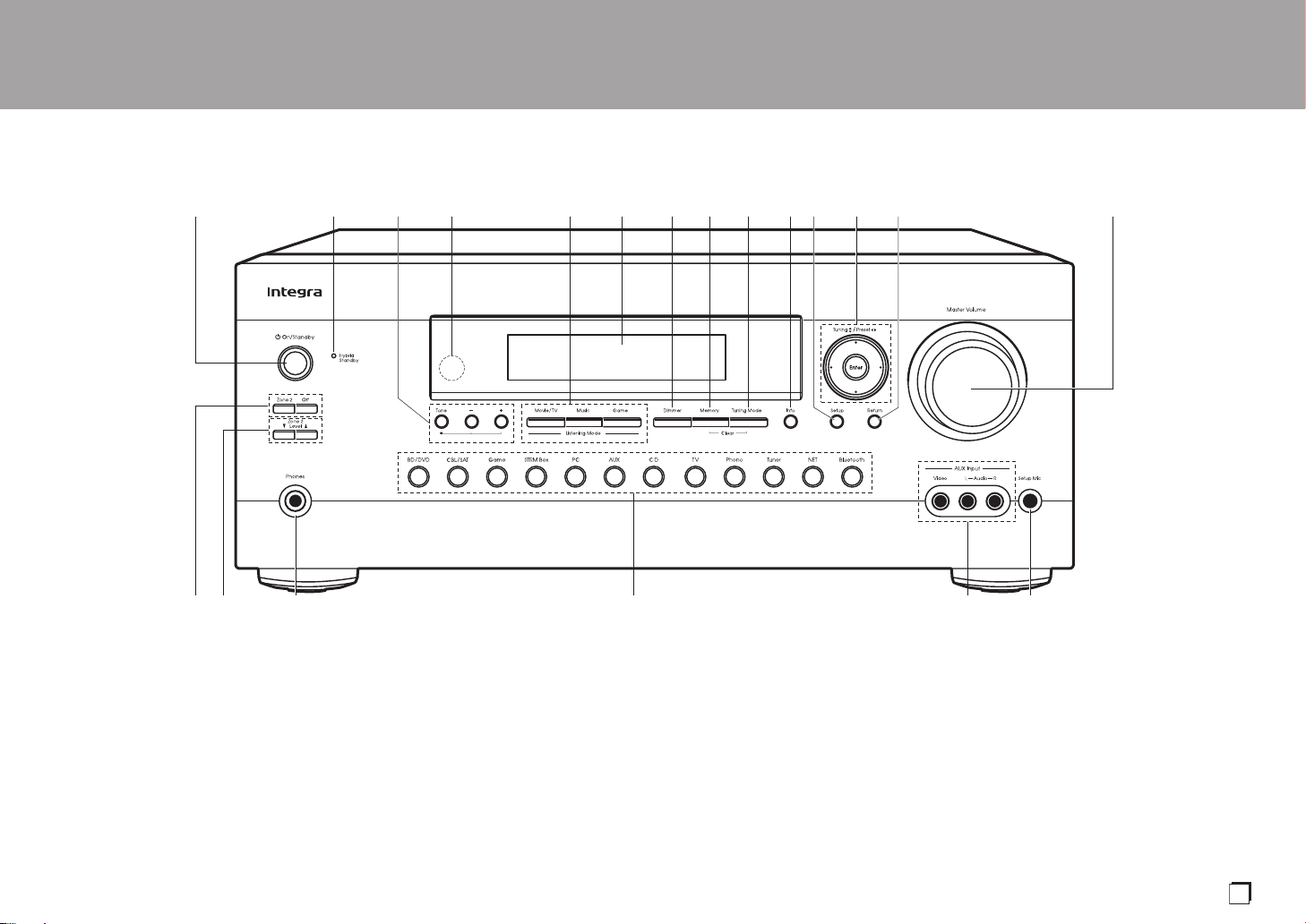
Part Names
Front Panel
1. Í On/Standby button
2. Hybrid Standby indicator: Lights if the unit enters standby mode when the features are
enabled that continue to work when this unit is in standby, such as HDMI Standby
Through and Network Standby.
3. You can adjust the sound quality of the front speakers. Press Tone to select the desired
setting from "Bass" and "Treble", and adjust with + and –.
4. Remote control sensor: Receives signals from the remote controller.
0 The signal range of the remote controller is within about 16´/5 m, at an angle of 20° on
the perpendicular axis and 30° to either side.
5. Listening Mode button: Press the Listening Mode button (above) repeatedly to select a
category from "Movie/TV", "Music", "Game", then turn the Listening Mode dial (below) to
change the mode (P30). (*)
6. Display (P4)
7. Dimmer button: You can adjust the brightness of the display in three steps. It cannot be
turned off completely.
8. Memory button: Used to register AM/FM radio stations (P28).
9. Tuning Mode button: Switches the tuning mode (P27).
10.
Info button: Switches the information on the display (P30).
11.
Setup button: You can show advanced setting items on the TV and display to provide you
with an even better experience. (*)
12.
Cursor buttons (S / T / W / X) and Enter button: Select the item with the cursors and
press Enter to confirm. Use them to tune to stations when using Tuner.
13.
Return button: Returns the display to the previous state.
14.
Master Volume
> Before Start >Part Names > Install > Initial Setup > Playback
(*)You can find details in the Advanced Manual.
En
4
> Before Start >Part Names > Install > Initial Setup > Playback
15.
Zone 2 button: Controls the multi-zone function (P29).
Off button: Switches the multi-zone function off (P29).
16.
Zone 2 Level 4/3 buttons: Adjust the volume of the
multi-zone feature (P29).
17.
Phones jack: Headphones with a standard plug
(Ø1/4"/6.3 mm) are connected.
18.
Input selector buttons: Switches the input to be played.
19.
AUX Input Video/Audio jacks: Input the video and audio
signals from an external player with an analog audio/
video cable.
20.
Setup Mic jack: The supplied speaker setup
microphone is connected.
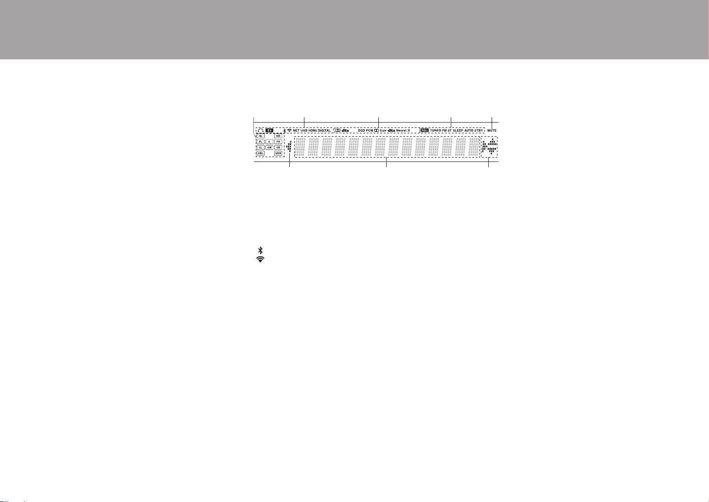
Display
1. Speaker/Channel display: Displays the output channel that
corresponds to the selected listening mode.
2. Lights in the following conditions.
Ë: When headphones are connected.
Z2: When ZONE 2 is on.
: When connected by BLUETOOTH.
: When connected by Wi-Fi.
NET: When "NET" is selected with the input selector and the unit is
connected to the network. It will flash if the connection to the network is
not correct.
USB: When "NET" is selected with the input selector and the unit is
connected by USB and the USB device is selected. Flashes if the USB
is not properly connected.
HDMI: When HDMI signals are input and the HDMI input is selected.
DIGITAL: When digital signals are input and the digital input is
selected.
3. Lights according to the type of input digital audio signals and the
listening mode.
4. Lights in the following conditions.
RDS (Australian models): Receiving RDS broadcasting.
TUNED: Receiving AM/FM radio.
FM ST: Receiving FM stereo.
SLEEP: When the sleep timer is set. (*)
AUTO STBY: Auto Standby is on. (*)
5. Flashes when muting is on.
6. Displays various information of the input signals. Characters that
cannot be displayed on this unit are replaced with asterisks ( * ).
7. This may light when performing operations with the "NET" input
selector.
(*)You can find details in the Advanced Manual.
5
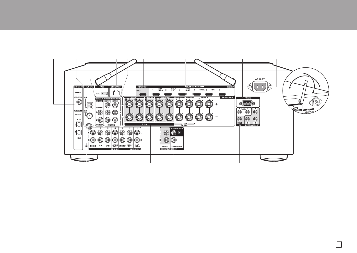
Rear Panel
1. DIGITAL IN OPTICAL/COAXIAL jacks: Input TV or AV component digital audio signals
with a digital optical cable or digital coaxial cable.
2. TUNER AM/FM 75Ω terminal: The supplied antennas are connected.
3. VIDEO IN jacks: Input the AV component video signals with an analog video cable.
4. Wireless antenna: Used for Wi-Fi connection or when using a BLUETOOTH wireless
technology enabled device. Adjust their angles according to the connection status.
5. USB port: A USB storage device is connected so that music files stored in it can be
played. You can also supply power (5 V/1 A) to USB devices with a USB cable.
6. ETHERNET port: Connect to the network with an Ethernet cable.
7. COMPONENT VIDEO IN jacks: Input the AV component video signals with a component
video cable. (Compatible only with 480i or 576i resolution.)
8. HDMI OUT jacks: Transmit video signals and audio signals with a HDMI cable connected
to a TV.
9. HDMI IN jacks: Transmit video signals and audio signals with a HDMI cable connected to
an AV component.
10.
RS232 port: For connection to the home control system. (*)
11.
AC INLET: The supplied power cord is connected.
12.
GND terminal: The ground wire of the turntable is connected.
13.
AUDIO IN jacks: Input TV or AV component audio signals with an analog audio cable.
14.
SPEAKERS terminals: Use a speaker cable to connect multichannel speakers for the
main room and speakers for a separate room (ZONE 2). (North American models are
compatible with banana plugs.)
15.
ZONE 2 PRE/LINE OUT jacks: Output audio signals with an analog audio cable to a pre-
main amplifier or power amplifier in a separate room (ZONE 2).
> Before Start >Part Names > Install > Initial Setup > Playback
180°
90°
(*)You can find details in the Advanced Manual.
En
6
> Before Start >Part Names > Install > Initial Setup > Playback
16.
SUBWOOFER PRE OUT jack: Connect a powered
subwoofer with a subwoofer cable. Up to two powered
subwoofers can be connected. The same signal is
output from each of the SUBWOOFER PRE OUT
jacks.
17.
IR IN A/B, IR OUT jacks: Allows you to connect a
multiroom remote control kit. (*)
18.
12V TRIGGER OUT A/B/C jacks: Allows you to
connect a device with 12V trigger input jack to enable
link operation between the device and the unit. (*)
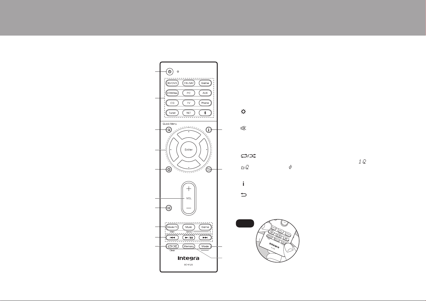
Remote Controller
1. Í On/Standby button
2. Input selector buttons: Switches the input to be played.
3. Q (Quick Menu) button: Settings such as "Tone" and "Level" can be made quickly
during play on the TV screen. (*)
4. Cursor buttons and Enter button: Select the item with the cursors and press Enter
to confirm your selection. When the folder or file lists are not shown on one
screen on the TV, press W / X to change the screen.
5. button: You can show advanced setting items on the TV and display to
provide you with an even better experience. (*)
6. Volume buttons
7. button: Temporarily mutes audio. Press again to cancel muting.
8. Listening Mode buttons: Allows you to select the listening mode (P30). (*)
Main/Zone 2 buttons: Controls the multi-zone function (P29). (The Zone 3 button
is not used with this unit.)
9. Play buttons: Used for play operations when playing Music Server or USB.
10.
button: You can start repeat/random play of the Music Server or USB.
Each time you press the button, the mode switches from (1-track repeat), to
(folder repeat), to (random).
Clear button: Deletes all characters you have entered when entering text on the
TV screen.
11.
button: Switches the information on the display and is used to operate RDS
(P28).
12.
button: Returns the display to the previous state.
13.
Mode button: Switches tuning to an AM/FM station between automatic tuning and
manual tuning (P27), and also used to control the multi-zone feature (P29).
14.
Memory button: Used to register AM/FM radio stations.
Tips
When the remote controller isn't working: The
remote controller may have switched to the mode
for controlling ZONE 2. While holding down Mode,
press Main for 3 seconds or more until the remote
indicator flashes once to switch it to the mode to
control the main room.
(*)You can find details in the Advanced Manual.
7
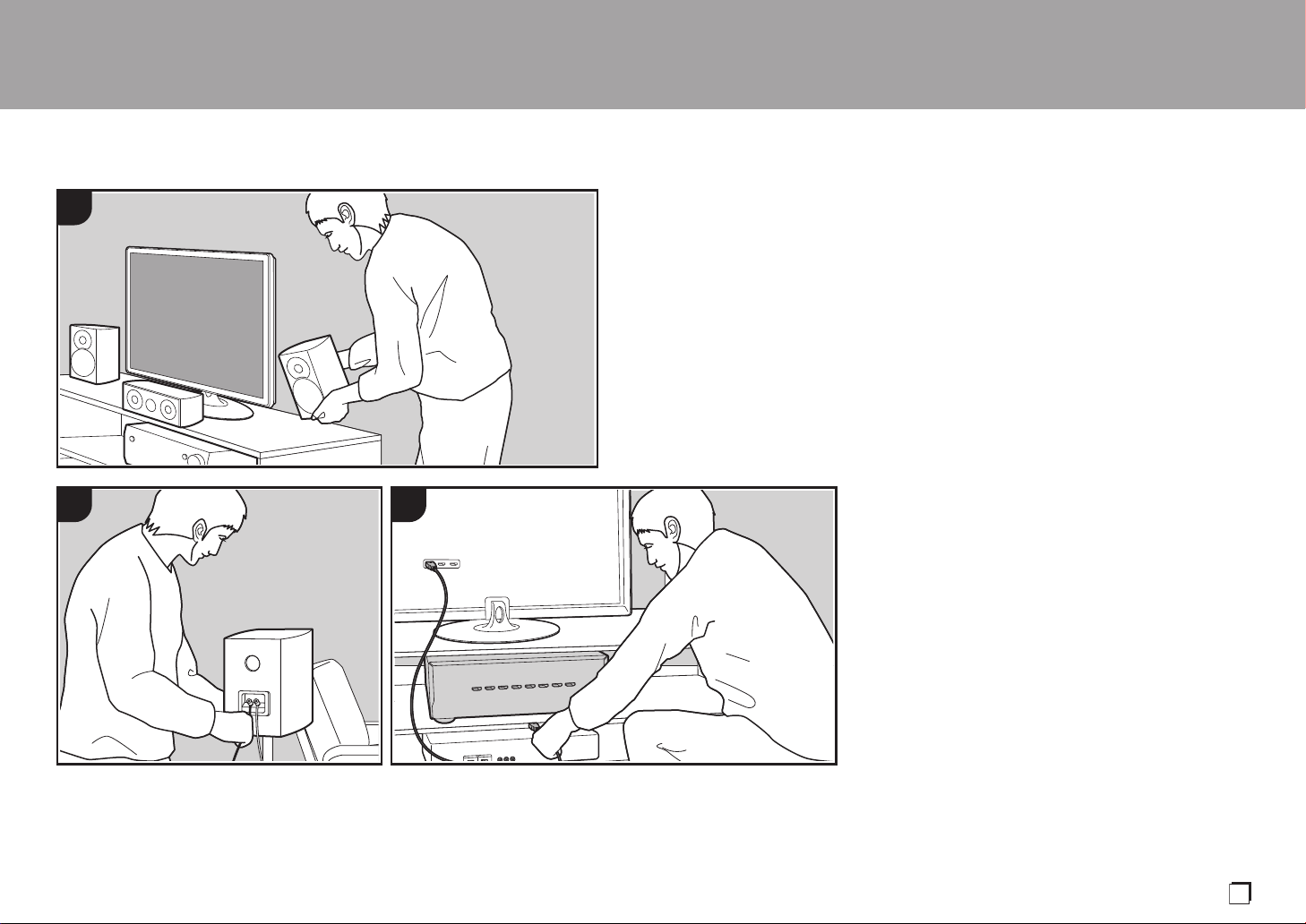
Installation procedure
This unit can be used in a number of ways, depending on
the layout of the speakers you are installing, and the
connections made to external devices. Read the following
to help make the installation process smoother.
Step1: Speaker Layout
Select the speaker layout that suits the types of speakers
you have and the conditions they will be used in from the
choices presented on pages P8 to P12, then install the
speakers by referring to the illustrations and explanations
on the relevant page. Speaker layouts include systems that
use surround back speakers, systems that use height
speakers, and systems that use Bi-Amping speakers. Also
refer to the combinations available in "Speaker
combinations" on P13.
Step2: Connect the Speakers
To connect the speaker systems to this unit, refer to P14 if
you are using a speaker layout described on one of P8 to
P11, and to P15 to use a speaker layout using Bi-Amping
speakers described on P12. The connection process will be
smoother if you refer to the illustrations and explanations
and prepare the required cables before hand.
Step3: Connect the TV & AV Components
Refer to P16 to P21 to connect your external devices such
as your TV, Blu-ray Disc Player, and also supplied
accessories such as the antennas. Also, P20 introduces
the Multi-zone Connection option that allows you to play
audio into rooms other than the main room. The connection
process will be smoother if you refer to the illustrations and
explanations, confirm the connection types on the external
devices, and prepare the required cables before hand.
> Before Start > Part Names >Install > Initial Setup > Playback
1
2 3
En
8
Step1: Speaker Layout
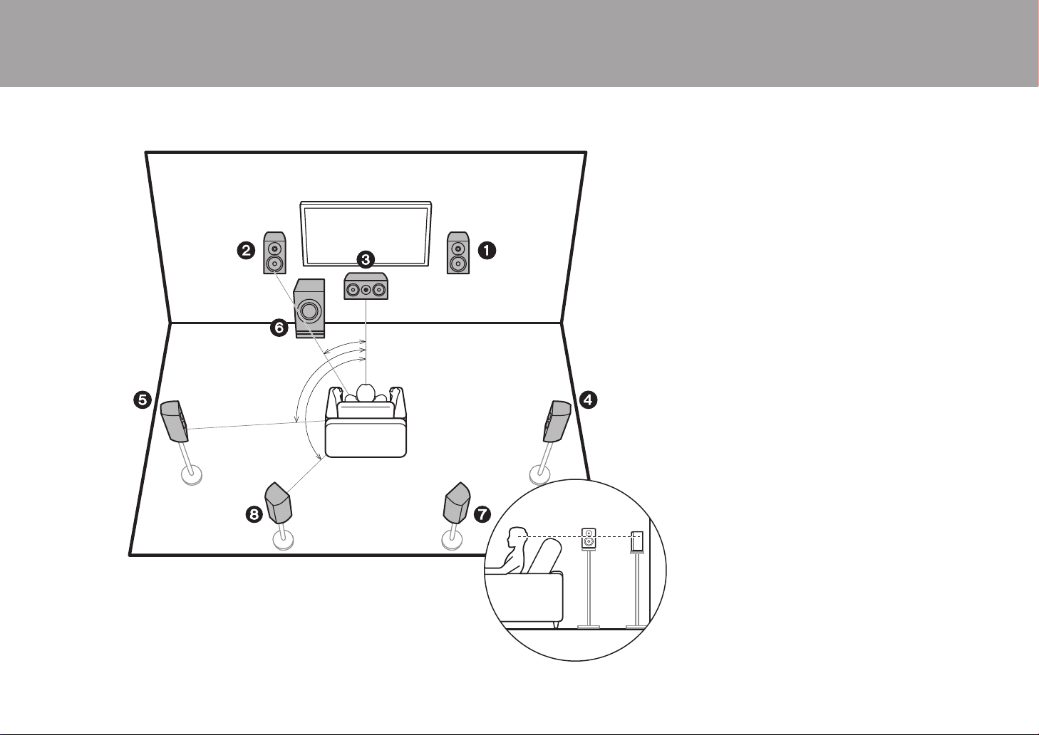
7.1 Channel System
Front speakers output front stereo sound and a center
speaker outputs center sound such as dialogs and vocals.
Surround speakers create back sound field. Powered
subwoofer reproduces bass sounds and creates rich sound
field.
This basic 5.1 Channel System with surround back
speakers added is called a 7.1 Channel System. The
connection of surround back speakers improves the sense
of envelopment and connectivity of sound created by the
back sound field and provides a more real sound field.
Furthermore, by installing surround back speakers, you can
select the Dolby Atmos listening mode, which realizes the
most up-to-date 3D sound, when the input format is Dolby
Atmos.
The front speakers should be positioned at ear height, while
the surround speakers should be positioned just above ear
height. Center speaker should be set up facing the listening
position. Placing the powered subwoofer between the
center speaker and a front speaker gives you a natural
sound even when playing music. The optimal positioning is
for surround back speakers to be at ear height.
0 If you are including surround back speakers in the setup,
surround speakers are required.
0 "Speaker combinations" (P13) introduces some detailed
examples of speaker combinations.
1,2 Front Speakers
3 Center Speaker
4,5 Surround Speakers
6 Powered Subwoofer
7,8 Surround Back Speakers
> Before Start > Part Names >Install > Initial Setup > Playback
*
1
*
2
*
3
½1: 22e to 30e, ½2: 90e to 110e, ½3: 135e to 150e
9
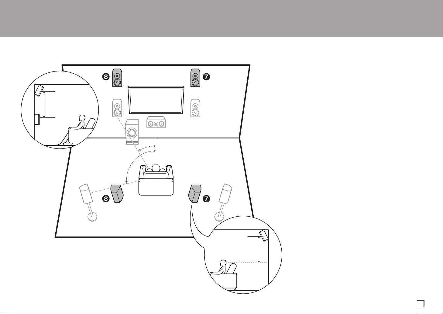
5.1.2 Channel System-1
(Front High Speakers/Rear High Speakers)
This is a basic 5.1 channel system consisting of front
speakers, a center speaker, surround speakers, and a
powered subwoofer, with the addition of front height
speakers or rear high speakers, which are both types of
height speakers. By installing height speakers, you can
select the Dolby Atmos listening mode, which realizes the
most up-to-date 3D sound including overhead sounds,
when the input format is Dolby Atmos. Front high speakers
or rear high speakers should be situated at least 3´/0.9 m
higher than the front speakers. Front high speakers should
be situated directly above the front speakers and the
distance between the rear high speakers should match the
distance between the front speakers. Both should be set up
facing the listening position.
0 "Speaker combinations" (P13) introduces some detailed
examples of speaker combinations.
7,8 Height Speakers
Choose one of the following:
0 Front High Speakers
0 Rear High Speakers
> Before Start > Part Names >Install > Initial Setup > Playback
*
1
*
2
3´ (0.9 m)
or more
3´ (0.9 m)
or more
½1: 22e to 30e, ½2: 120e
En
10
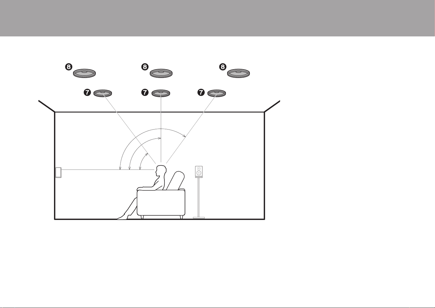
5.1.2 Channel System-2
(Ceiling Speakers)
This is a basic 5.1 channel system consisting of front
speakers, a center speaker, surround speakers, and a
powered subwoofer, with the addition of top front speakers,
top middle speakers, or top rear speakers, which are types
of height speakers. By installing height speakers, you can
select the Dolby Atmos listening mode, which realizes the
most up-to-date 3D sound including overhead sounds,
when the input format is Dolby Atmos. Fit top front speakers
on the ceiling forward of the seating position, top middle
speakers on the ceiling directly above the seating position,
and top rear speakers on the ceiling behind the seating
position. The distance between each pair should match the
distance between the two front speakers.
0 Dolby Laboratories recommends placing this type of
height speakers to obtain the best Dolby Atmos effect.
0 "Speaker combinations" (P13) introduces some detailed
examples of speaker combinations.
7,8 Height Speakers
Choose one of the following:
0 Top Front Speakers
0 Top Middle Speakers
0 Top Rear Speakers
> Before Start > Part Names >Install > Initial Setup > Playback
*
1
*
2
*
3
½1: 30e to 55e, ½2: 65e to 100e, ½3: 125e to 150e
 Loading...