


DTR-50.5
Table of contents
 Loading...
AV Receiver
DTR-50.5
Instruction Manual
En-2
Safety Information and Introduction
Important Safety Instructions
1. Read these instructions.
2. Keep these instructions.
3. Heed all warnings.
4. Follow all instructions.
5. Do not use this apparatus near water.
6. Clean only with dry cloth.
7. Do not block any ventilation openings. Install in
accordance with the manufacturer’s instructions.
8. Do not install near any heat sources such as
radiators, heat registers, stoves, or other
apparatus (including amplifiers) that produce
heat.
9. Do not defeat the safety purpose of the polarized
or grounding-type plug. A polarized plug has two
blades with one wider than the other. A grounding
type plug has two blades and a third grounding
prong. The wide blade or the third prong are
provided for your safety. If the provided plug does
not fit into your outlet, consult an electrician for
replacement of the obsolete outlet.
10. Protect the power cord from being walked on or
pinched particularly at plugs, convenience
receptacles, and the point where they exit from
the apparatus.
11. Only use attachments/accessories specified by
the manufacturer.
12. Use only with the cart,
stand, tripod, bracket, or
table specified by the
manufacturer, or sold with
the apparatus. When a cart
is used, use caution when
moving the cart/apparatus
combination to avoid injury
from tip-over.
13. Unplug this apparatus during lightning storms or
when unused for long periods of time.
14. Refer all servicing to qualified service personnel.
Servicing is required when the apparatus has
been damaged in any way, such as power-supply
cord or plug is damaged, liquid has been spilled or
objects have fallen into the apparatus, the
apparatus has been exposed to rain or moisture,
does not operate normally, or has been dropped.
15. Damage Requiring Service
Unplug the apparatus from the wall outlet and
refer servicing to qualified service personnel
under the following conditions:
A. When the power-supply cord or plug is
damaged,
B. If liquid has been spilled, or objects have fallen
into the apparatus,
C. If the apparatus has been exposed to rain or
water,
D. If the apparatus does not operate normally by
following the operating instructions. Adjust
only those controls that are covered by the
operating instructions as an improper
adjustment of other controls may result in
damage and will often require extensive work
by a qualified technician to restore the
apparatus to its normal operation,
E. If the apparatus has been dropped or
damaged in any way, and
F. When the apparatus exhibits a distinct change
in performance this indicates a need for
service.
16. Object and Liquid Entry
Never push objects of any kind into the apparatus
through openings as they may touch dangerous
voltage points or short-out parts that could result
in a fire or electric shock.
The apparatus shall not be exposed to dripping or
splashing and no objects filled with liquids, such
as vases shall be placed on the apparatus.
Don’t put candles or other burning objects on top
of this unit.
17. Batteries
Always consider the environmental issues and
follow local regulations when disposing of
batteries.
18. If you install the apparatus in a built-in installation,
such as a bookcase or rack, ensure that there is
adequate ventilation.
Leave 20 cm (8") of free space at the top and
sides and 10 cm (4") at the rear. The rear edge of
the shelf or board above the apparatus shall be
set 10 cm (4") away from the rear panel or wall,
creating a flue-like gap for warm air to escape.
WARNING:
TO REDUCE THE RISK OF FIRE OR ELECTRIC
SHOCK, DO NOT EXPOSE THIS APPARATUS TO RAIN
OR MOISTURE.
CAUTION:
TO REDUCE THE RISK OF ELECTRIC SHOCK, DO NOT
REMOVE COVER (OR BACK). NO USER-SERVICEABLE
PARTS INSIDE. REFER SERVICING TO QUALIFIED
SERVICE PERSONNEL.
The lightning flash with arrowhead symbol, within
an equilateral triangle, is intended to alert the
user to the presence of uninsulated “dangerous
voltage” within the product’s enclosure that may
be of sufficient magnitude to constitute a risk of
electric shock to persons.
The exclamation point within an equilateral
triangle is intended to alert the user to the
presence of important operating and
maintenance (servicing) instructions in the
literature accompanying the appliance.
WARNING
RISK OF ELECTRIC SHOCK
DO NOT OPEN
RISQUE DE CHOC ELECTRIQUE
NE PAS OUVRIR
A VIS
PORTABLE CART WARNIN
G
S3125A

Safety Information and Introduction
En-3
Precautions
1. Recording Copyright—Unless it’s for personal
use only, recording copyrighted material is illegal
without the permission of the copyright holder.
2. AC Fuse—The AC fuse inside the unit is not user-
serviceable. If you cannot turn on the unit, contact
the dealer from whom you purchased this unit.
3. Care—Occasionally you should dust the unit all
over with a soft cloth. For stubborn stains, use a
soft cloth dampened with a weak solution of mild
detergent and water. Dry the unit immediately
afterwards with a clean cloth. Don’t use abrasive
cloths, thinners, alcohol, or other chemical
solvents, because they may damage the finish or
remove the panel lettering.
4. Power
WARNING
BEFORE PLUGGING IN THE UNIT FOR THE
FIRST TIME, READ THE FOLLOWING SECTION
CAREFULLY.
AC outlet voltages vary from country to country.
Make sure that the voltage in your area meets the
voltage requirements printed on the unit’s rear
panel (e.g., AC 230 V, 50 Hz or AC 120 V, 60 Hz).
The power cord plug is used to disconnect this
unit from the AC power source. Make sure that
the plug is readily operable (easily accessible) at
all times.
For models with [Power] button, or with both
[Power] and [On/Standby] buttons:
Pressing the [Power] button to select OFF mode
does not fully disconnect from the mains. If you do
not intend to use the unit for an extended period,
remove the power cord from the AC outlet.
For models with [On/Standby] button only:
Pressing the [On/Standby] button to select
Standby mode does not fully disconnect from the
mains. If you do not intend to use the unit for an
extended period, remove the power cord from the
AC outlet.
5. Preventing Hearing Loss
Caution
Excessive sound pressure from earphones and
headphones can cause hearing loss.
6. Batteries and Heat Exposure
Warning
Batteries (battery pack or batteries installed) shall
not be exposed to excessive heat as sunshine,
fire or the like.
7. Never Touch this Unit with Wet Hands—Never
handle this unit or its power cord while your hands
are wet or damp. If water or any other liquid gets
inside this unit, have it checked by the dealer from
whom you purchased this unit.
8. Handling Notes
• If you need to transport this unit, use the original
packaging to pack it how it was when you
originally bought it.
• Do not leave rubber or plastic items on this unit
for a long time, because they may leave marks
on the case.
• This unit’s top and rear panels may get warm
after prolonged use. This is normal.
• If you do not use this unit for a long time, it may
not work properly the next time you turn it on, so
be sure to use it occasionally.
For U.S. and Canadian models
FCC CAUTION
Changes or modifications not expressly approved by
the party responsible for compliance could void the
user’s authority to operate the equipment.
Note:
This equipment has been tested and found to comply
with the limits for a Class B digital device, pursuant to
part 15 of the FCC Rules. These limits are designed
to provide reasonable protection against harmful
interference in a residential installation. This
equipment generates, uses and can radiate radio
frequency energy and, if not installed and used in
accordance with the instructions, may cause harmful
interference to radio communications. However, there
is no guarantee that interference will not occur in a
particular installation. If this equipment does cause
harmful interference to radio or television reception,
which can be determined by turning the equipment off
and on, the user is encouraged to try to correct the
interference by one or more of the following
measures:
–Reorient or relocate the receiving antenna.
–Increase the separation between the equipment
and receiver.
–Connect the equipment into an outlet on a circuit
different from that to which the receiver is
connected.
–Consult the dealer from whom you purchased this
unit or an experienced radio/TV technician for help.
This device complies with Industry Canada licence-
exempt RSS standard(s). Operation is subject to the
following two conditions: (1) this device may not
cause interference, and (2) this device must accept
any interference, including interference that may
cause undesired operation of the device.
Le présent appareil est conforme aux CNR d’Industrie
Canada applicables aux appareils radio exempts de
licence. L’exploitation est autorisée aux deux
conditions suivantes : (1) l’appareil ne doit pas
produire de brouillage, et (2) l’utilisateur de l’appareil
doit accepter tout brouillage radioélectrique subi,
même si le brouillage est susceptible d’en
compromettre le fonctionnement.
This transmitter must not be co-located or operated in
conjunction with any other antenna or transmitter.
Safety Information and Introduction
En-4
RF Exposure Compliance
This equipment complies with FCC/IC radiation
exposure limits set forth for an uncontrolled
environment and meets the FCC radio frequency
(RF) Exposure Guidelines in Supplement C to OET65
and RSS-102 of the IC radio frequency (RF)
Exposure rules. This equipment has very low levels of
RF energy that it deemed to comply without
maximum permissive exposure evaluation (MPE).
But it is desirable that it should be installed and
operated keeping the radiator at least 20 cm or more
away from person’s body (excluding extremities:
hands, wrists, feet and ankles).
Cet équipement est conforme aux limites d’exposition
aux rayonnements énoncées pour un environnement
non contrôlé et respecte les régles les
radioélectriques (RF) de la FCC lignes directrices
d’exposition dans le Supplément C à OET65 et
d’exposition aux fréquences radioélectriques (RF)
CNR-102 de l’IC. Cet équipement émet une énergie
RF trés faible qui est considérée conforme sans
évaluation de l’exposition maximale autorisée.
Cependant, cet équipement doit être installé et utilisé
en gardant une distance de 20 cm ou plus entre le
dispositif rayonnant et le corps (à l’exception des
extrémités : mains, poignets, pieds et chevilles).
For Canadian Models
NOTE: THIS CLASS B DIGITAL APPARATUS
COMPLIES WITH CANADIAN ICES-003.
For models having a power cord with a polarized
plug:
CAUTION: TO PREVENT ELECTRIC SHOCK,
MATCH WIDE BLADE OF PLUG TO WIDE SLOT,
FULLY INSERT.
Modèle pour les Canadien
REMARQUE: CET APPAREIL NUMÉRIQUE DE
LA CLASSE B EST CONFORME À LA NORME
NMB-003 DU CANADA.
Sur les modèles dont la fiche est polarisée:
ATTENTION: POUR ÉVITER LES CHOCS
ÉLECTRIQUES, INTRODUIRE LA LAME LA PLUS
LARGE DE LA FICHE DANS LA BORNE
CORRESPONDANTE DE LA PRISE ET POUSSER
JUSQU’AU FOND.
Thank you for purchasing an Integra AV
Receiver. Please read this manual thoroughly
before making connections and plugging in the
unit.
Following the instructions in this manual will
enable you to obtain optimum performance and
listening enjoyment from your new AV Receiver.
Please retain this manual for future reference.
Supplied Accessories
Make sure you have the following accessories:
*
In catalogs and on packaging, the letter at the end of the
product name indicates the color. Specifications and
operations are the same regardless of color.
Complies with
IDA Standards
DA106032
23764/SDPPI/2012
2371
TRA
REGISTERED No
ER0086260/12
DEALER No
527090
TA-20120424004
Indoor FM antenna (➔ page 20)
AM loop antenna (➔ page 20)
Power cord (➔ page 22)
Speaker cable labels (➔ page 13)
Speaker setup microphone (➔ page 26)
Remote controller (RC-841M) and two batteries (AA/R6)
(➔ page 11)

Safety Information and Introduction
En-5
Table of Contents
Safety Information and Introduction
Important Safety Instructions ......................................2
Precautions ...................................................................3
Supplied Accessories...................................................4
Table of Contents..........................................................5
Features .........................................................................6
Front & Rear Panels......................................................7
Front Panel..................................................................7
Display ........................................................................8
Rear Panel ..................................................................9
Remote Controller.......................................................10
Controlling the AV Receiver......................................10
Connections
Connecting the AV Receiver......................................12
Connecting Your Speakers .......................................12
Connecting the TV/AV components..........................16
About RIHD-compatible components........................17
Operations that can be performed
with RIHD connection.............................................18
Confirm the settings ..................................................18
Connection Tips ........................................................18
Connecting the Antennas..........................................20
Connecting Integra/Onkyo RI Components ..............21
Using Headphones....................................................21
Turning On & Basic Operations
Turning On/Off the AV Receiver ................................22
Connecting the Power Cord......................................22
Turning On ................................................................22
Turning Off ................................................................22
Firmware Update Notification....................................23
About the Hybrid Standby indicator...........................23
Initial Setup..................................................................23
Selecting the Language
for the On-screen Setup Menus .............................23
Audyssey MultEQ: Auto Setup..................................23
Source Connection....................................................24
Remote Mode Setup .................................................24
Network Connection..................................................24
Terminating the Initial Setup .....................................24
Using the Automatic Speaker Setup.........................25
Performing Wireless LAN Setup ............................... 28
Playback
Playback ......................................................................30
Controlling Contents of USB or Network Devices..... 31
Understanding Icons on the Display .........................32
Playing an Audio from Bluetooth-enabled Device ....32
Playing a USB Device............................................... 33
Listening to TuneIn ...................................................33
Registering Other Internet Radio ..............................35
Changing the Icon Layout
on the Network Service Screen.............................. 35
Playing Music Files on a Server (DLNA) ..................35
Playing Music Files on a Shared Folder ...................37
Remote Playback...................................................... 38
Listening to AM/FM Radio ........................................39
Playing Audio and Video from Separate Sources..... 41
Using the Listening Modes .......................................42
Displaying Source Information.................................. 50
Using the Sleep Timer ..............................................50
Setting the Display Brightness..................................50
Changing the Input Display....................................... 51
Muting the AV Receiver ............................................51
Selecting Speaker Layout.........................................51
Using the Whole House Mode ..................................51
Using Easy Macros...................................................52
Using the Home Menu ..............................................53
Advanced Operations
On-screen Setup......................................................... 54
Using the Quick Setup ..............................................54
Using the Audio Settings of Quick Setup..................55
Using the Setup Menu (Home) .................................58
Setup Menu Items..................................................... 58
1. Input/Output Assign ..............................................59
2. Speaker Setup...................................................... 62
3. Audio Adjust.......................................................... 65
4. Source Setup........................................................ 67
5. Listening Mode Preset .......................................... 71
6. Miscellaneous ....................................................... 72
7. Hardware Setup.................................................... 73
8. Remote Controller Setup ......................................77
9. Lock Setup............................................................77
Multi Zone.................................................................... 78
Making Multi Zone Connections ...............................78
Setting the Zone 2/3 Out .......................................... 79
Controlling Multi Zone Components ......................... 79
Using the 12V Triggers............................................. 80
Using the Remote Controller in Zone
and Multiroom Control Kits..................................... 81
Controlling Other Components
Controlling Other Components................................. 82
Preprogrammed Remote Control Codes .................. 82
Looking up for Remote Control Codes .....................82
Entering Remote Control Codes............................... 82
Remapping Colored Buttons .................................... 83
Remote Control Codes for Integra/Onkyo
Components Connected via RI .............................. 83
Resetting the Remote Mode Buttons........................ 83
Resetting the Remote Controller ..............................84
Controlling Other Components................................. 84
Using the Integra/Onkyo Dock.................................. 87
Controlling Your iPod/iPhone ................................... 88
Learning Commands ................................................ 89
Using Normal Macros............................................... 90
Appendix
Troubleshooting ......................................................... 91
Firmware Update ........................................................ 99
About HDMI............................................................... 102
Network/USB Features............................................. 103
License and Trademark Information ...................... 105
Specifications ........................................................... 106
To reset the AV receiver, see page 91.

Safety Information and Introduction
En-6
Features
Amplifier
• 130 Watts/Channel @ 8 ohms (FTC)
• 180 Watts/Channel @ 6 ohms (IEC)
• 215 Watts/Channel @ 6 ohms (JEITA)
• WRAT–Wide Range Amplifier Technology
(5 Hz to 100 kHz bandwidth)
• Optimum Gain Volume Circuitry
• H.C.P.S. (High Current Power Supply) Massive
High Power Transformer
• 3 Stage Inverted Darlington Amplifier Design
Processing
• THX Select2 Plus Certified
• Incorporates Qdeo™ technology for HDMI Video
Upscaling (to 4K Compatible)
• HDMI (Audio Return Channel, 3D, DeepColor,
x.v.Color, Lip Sync, 4K (up-scaling and
Passthrough), DTS-HD Master Audio, DTS-HD High
Resolution Audio, Dolby TrueHD, Dolby Digital Plus,
DSD and Multi-CH PCM)
• Dolby TrueHD and DTS-HD Master Audio
• Dolby Pro Logic IIz and Audyssey DSX
®
• Non-Scaling Configuration
• A-Form Listening Mode Memory
• Direct Mode
• Music Optimizer for Compressed Digital Music files
• Phase Matching Bass System
• 192 kHz/24-bit D/A Converters
• Powerful and Highly Accurate 32-bit Processing
DSP
• Jitter Cleaning Circuit Technology
Connections
• 8 HDMI Inputs (1 on front panel) and 2 Outputs
• 4K (up-scaling and Passthrough
*
)-compatible HDMI
Inputs
* Compatible with HDMI IN 1 to HDMI IN 4 only
• Integra/Onkyo p for System Control
• 5 Digital Inputs (2 Optical/3 Coaxial)
• Component Video Switching (2 Inputs/1 Output)
• Banana Plug-Compatible Speaker Posts
• Powered Zone 2
• Zone 2/3 Pre/Line Out
• IR Input/Output and 12 V Triggers
• RS232 Port for Interface Control
• Bi-Amping Capability for FL/FR with FHL/FHR
• Internet Radio Connectivity
• Network Capability for Streaming Audio Files
• Wi-Fi (Wireless LAN) Connectivity
• Wireless Music Playback via Bluetooth
• Front-Panel USB Input for Memory Devices
• MHL-Enabled AUX Front Input
Miscellaneous
• 40 FM/AM Presets
• Audyssey MultEQ
®
to correct room acoustic
problems
• Audyssey Dynamic EQ
®
for loudness correction
• Audyssey Dynamic Volume
®
to maintain optimal
listening level and dynamic range
• Crossover Adjustment
(40/45/50/55/60/70/80/90/100/110/120/130/150/
200 Hz)
• A/V Sync Control Function (up to 800 ms)
• Auto Standby Function
• On-Screen Display via HDMI
• Preprogrammed (with onscreen display setup)
RI-Compatible Learning Remote with 4 Activities
and Mode-Key LEDs
Safety Information and Introduction
En-7
Front & Rear Panels
For detailed information, see the pages in
parentheses.
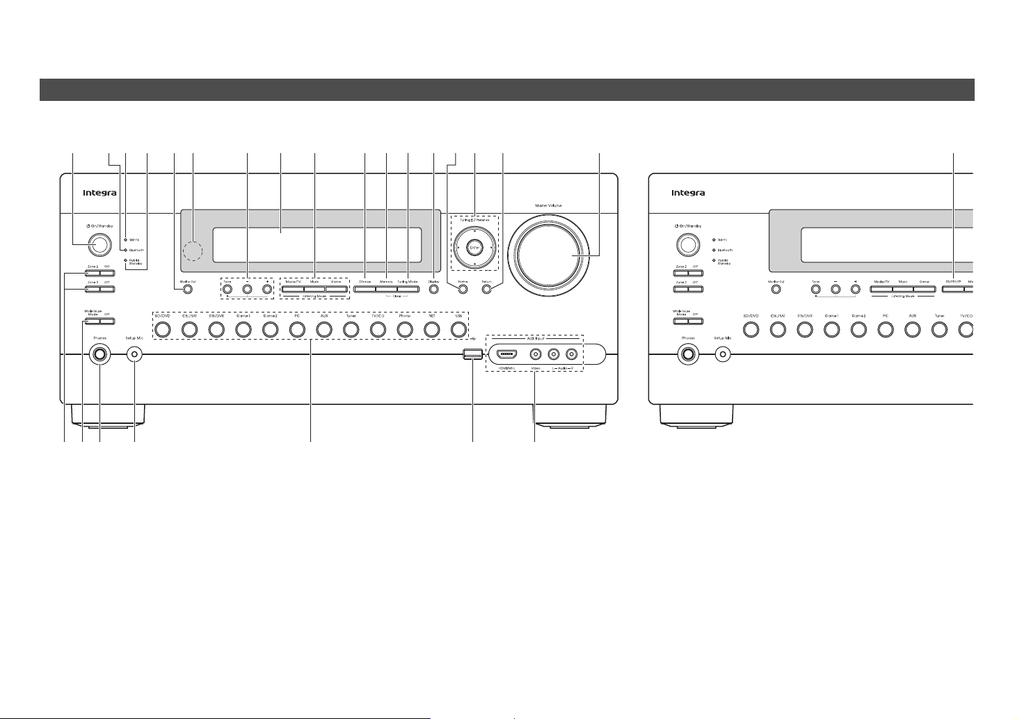
a 8On/Standby button (22)
b Bluetooth indicator (32, 77)
c Wi-Fi indicator (28)
d Hybrid Standby indicator (23)
e Monitor Out button (59)
f Remote control sensor (11)
g Tone and Tone Level buttons (55, 80)
h Display (8)
i Listening Mode buttons (42)
j Dimmer button (North American models) (50)
k Memory button (39)
l Tuning Mode button (39)
m Display button (50)
n Home button (53)
o Tuning q/w (39), Preset e/r (39), cursor and
Enter buttons
p Return button
q Master Volume control (30)
r Zone 2/Zone 3 and Off buttons (79)
s Whole House Mode and Off buttons (51)
t Phones jack (21)
u Setup Mic jack (26)
v Input selector buttons (30)
w USB port (33)
x AUX Input jacks (17)
y RT/PTY/TP button (Australian models) (40)
Front Panel
(North American models) (Australian models)
afeh
g jkl
nmop qbc
vxtsurw
d i y
Safety Information and Introduction
En-8
s
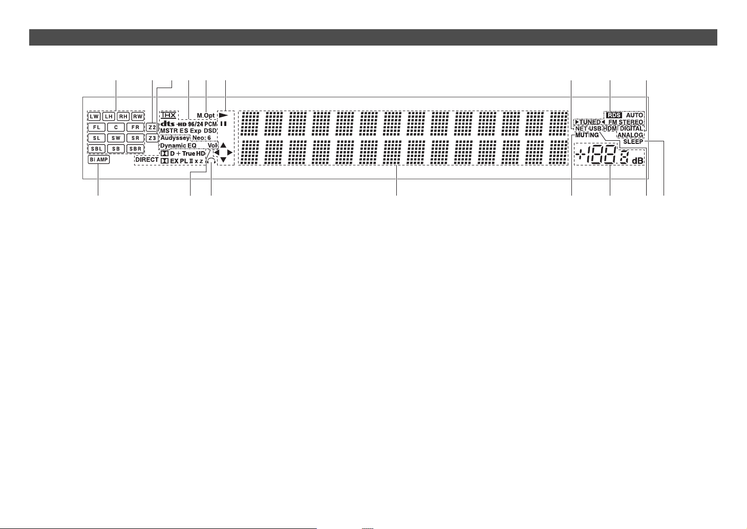
For detailed information, see the pages in
parentheses.
a Speaker/channel indicators
b Z2 (Zone 2) indicator (79)
c Z3 (Zone 3) indicator (79)
d Listening mode and format indicators (42, 71)
e M.Opt (Music Optimizer) indicator (56)
f 1, 3 and cursor indicators (33)
g NET indicator (33 to 37, 77)
h Tuning indicators
RDS indicator (excluding North American
models) (40)
AUTO indicator (39)
TUNED indicator (39)
FM STEREO indicator (39)
i Input indicators (19)
HDMI indicator (74)
DIGITAL indicator
ANALOG indicator
j Bi AMP indicator
k Audyssey indicator (25, 67)
Dynamic EQ indicator (67)
Dynamic Vol indicator (67)
l Headphone indicator (21)
m Message area
n MUTING indicator (51)
o Volume level
p USB indicator (33)
q SLEEP indicator (50)
Display
dcb fehga i
ljmnopqk
Safety Information and Introduction
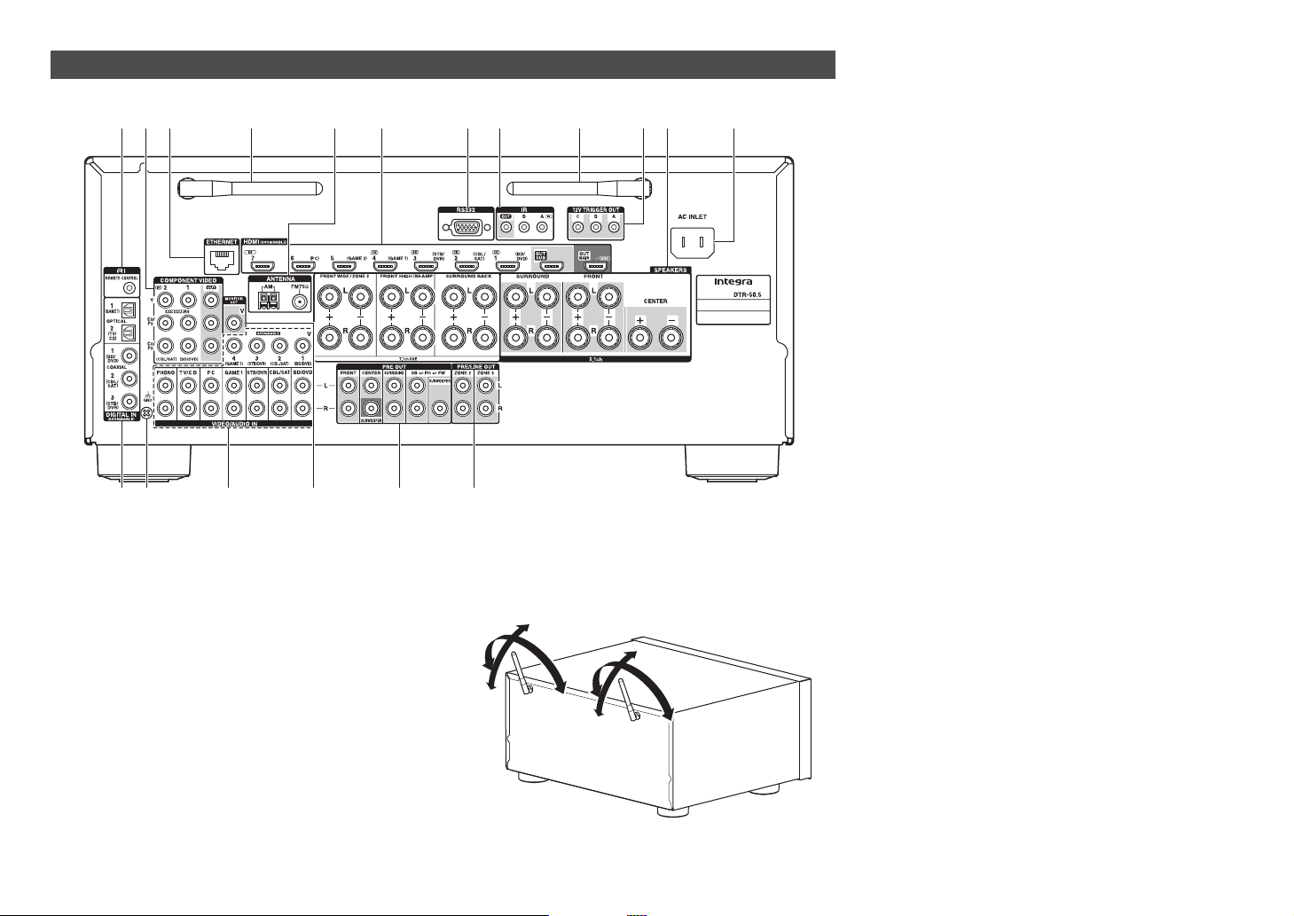
En-9
See “Connecting the AV Receiver” for connection
(➔ pages 12 to 21).
a uREMOTE CONTROL jack
b COMPONENT VIDEO IN and OUT jacks
c ETHERNET port
d Wireless antenna
When the AV receiver is connected to the network
by wireless, adjust the position of the antenna
(➔ pages 28, 32).
Rear Panel
lm n o p q
aecd dbfghikj
90°
90°
180°
180°
e FM ANTENNA jack and AM ANTENNA terminal
f HDMI IN and HDMI output (HDMI OUT MAIN and
HDMI OUT SUB) jacks
g RS232 port
Terminal for control.
h IR IN A/B and OUT jacks
i 12V TRIGGER OUT A/B/C jacks
j SPEAKERS terminals
(FRONT L/R, CENTER, SURROUND L/R,
SURROUND BACK L/R, FRONT HIGH/Bi-AMP
L/R and FRONT WIDE/ZONE 2 L/R)
k AC INLET
l DIGITAL IN COAXIAL and OPTICAL jacks
m GND screw
n Composite video and analog audio jacks
(BD/DVD IN, CBL/SAT IN, STB/DVR IN, GAME 1
IN, PC IN, TV/CD IN, PHONO IN)
o MONITOR OUT V jack
p PRE OUT jacks
(FRONT L/R, CENTER, SURROUND L/R,
SB or FH or FW
*
L/R, SUBWOOFER)
*
SB···Surround Back, FH···Front High, FW···Front Wide
q ZONE 2 and ZONE 3 PRE/LINE OUT jacks
Safety Information and Introduction
En-10
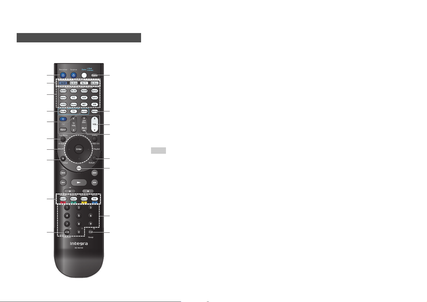
Remote Controller
To control the AV receiver, press Receiver to select
Receiver mode.
For detailed information, see the pages in
parentheses.
a 8Receiver button (22)
b Activities buttons (52, 90)
c Remote Mode/Input Selector buttons (30)
d SP (speaker layout) button (51)
e q/w/e/r and Enter buttons
f Q Setup button (54)
g Listening Mode buttons (42)
h Dimmer button (50)
i Display button (50)
j Muting button (51)
k VOL q/w button (30)
l Return button
m Home button (53)
n Sleep button (50)
Tip
• You can also use the remote controller to control Integra/
Onkyo Blu-ray Disc/DVD player, CD player, and other
components.
See “Entering Remote Control Codes” for more details
(➔ page 82).
■ Controlling the tuner
To control the AV receiver’s tuner, press Tuner (or
Receiver).
You can select AM or FM by pressing Tuner
repeatedly.
a q/w buttons (39)
b D.TUN button (39)
c Display button
d CH +/– button (40)
e Number buttons (39)
*1
When you want to change the remote controller mode
(target component) without changing the current input
source, press Mode and within about 8 seconds, press
Remote Mode. Then, using the same AV receiver’s
remote controller, you can control the component
corresponding to the button you pressed.
*2
These buttons can also be used when a Remote Mode
other than Receiver mode is selected.
Controlling the AV Receiver
n
e
h
b
d
f
g
e
a
j
k
d
l
m
c
b
a
c
i
*1
*2
*2
*2
*2
Receiver
Safety Information and Introduction
En-11
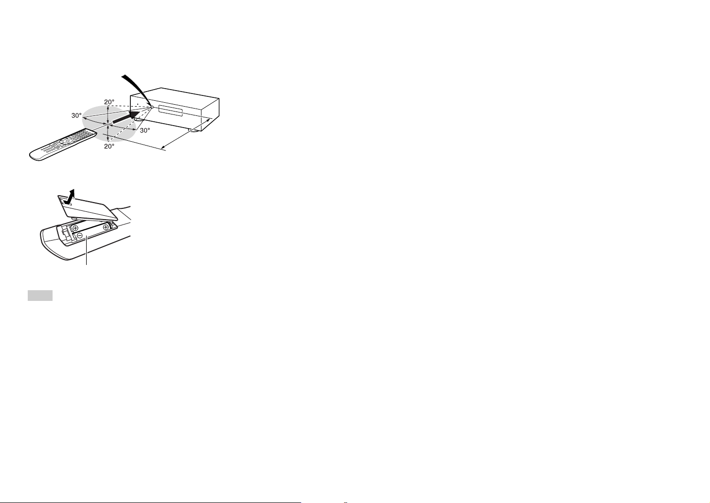
■ Aiming the remote controller
To use the remote controller, point it at the AV
receiver’s remote control sensor, as shown below.
■ Installing the batteries
Note
• If the remote controller doesn’t work reliably, try replacing
the batteries.
• Don’t mix new and old batteries or different types of
batteries.
• If you intend not to use the remote controller for a long time,
remove the batteries to prevent damage from leakage or
corrosion.
• Remove expired batteries as soon as possible to prevent
damage from leakage or corrosion.
Remote control sensor
AV receiver
Approx. 16 ft. (5 m)
Batteries (AA/R6)

En-12
Connections
Connecting the AV
Receiver
Speaker Configuration
The following table indicates the channels you should
use depending on the number of speakers that you
have.
No matter how many speakers you use, a powered
subwoofer is recommended for a really powerful and
solid bass.
To get the best from your surround sound system,
you need to set the speaker settings automatically
(➔ page 25) or manually (➔ page 62).
*1
Front high, surround back and front wide speakers
cannot be used at the same time.
Using Powered Subwoofers
To find the best position for your subwoofer, while
playing a movie or some music with good bass,
experiment by placing your subwoofer at various
positions within the room, and choose the one that
provides the most satisfying results.
You can connect the powered subwoofer with two
SUBWOOFER PRE OUT jacks respectively.
The same signal is output from each jack.
Tip
• If your subwoofer is unpowered and you’re using an
external amplifier, connect the subwoofer pre out jack to an
input on the amplifier.
Connections
Connecting Your Speakers
a b
Front speakers
c
Center speaker
d e
Surround speakers
f
Subwoofer(s)
G H
Surround back speakers
I J
Front high speakers
K L
Front wide speakers
I
J
K
L
a
bc
d
e
f
G
H
Number of
speakers
2 3 4 5 6 7 7 7 8 8 9 9 9 10 11
Front
speakers
✔✔✔✔✔✔✔✔✔✔✔✔✔✔ ✔
Center
speaker
✔ ✔✔✔✔✔✔✔✔✔✔✔ ✔
Surround
speakers
✔✔✔✔✔✔✔✔✔✔✔✔ ✔
Surround
back
speaker
*1
✔✔✔✔
Surround
back
speakers
*1
✔✔✔✔
Front high
speakers
*1
✔✔✔✔✔✔
Front wide
speakers
*1
✔✔✔✔✔✔
Speaker Configuration
5.1-channel:
a b c d e f
7.1-channel:
a b c d e f
+
G H
7.1-channel:
a b c d e f
+
I J
7.1-channel:
a b c d e f
+
K L
Corner
position
1/3 of wall
position
Connections
En-13
Attaching the Speaker Cable Labels
The speaker terminals are color-coded for
identification purpose.
The supplied speaker cable labels are also color-
coded and you should attach them to the positive (+)
side of each speaker cable in accordance with the
table above. Then all you need to do is to match the
color of each label to the corresponding speaker
terminal.
Speaker Color
Front left, Front high left, Front wide
left, Zone 2 left
White
Front right, Front high right, Front wide
right, Zone 2 right
Red
Center Green
Surround left Blue
Surround right Gray
Surround back left Brown
Surround back right Tan
Connections
En-14
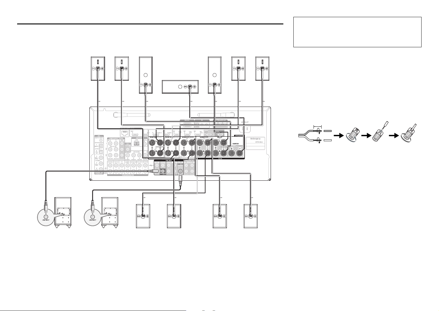
Connecting the Speaker Cables/Powered Subwoofers
Please connect a , b , c , d , e and f for 5.1-channel surround.
• Pay close attention to speaker wiring polarity. In other words, connect positive (+) terminals only to positive (+)
terminals, and negative (–) terminals only to negative (–) terminals. If you get them the wrong way around, the
sound will be out of phase and will sound unnatural.
Surround
speaker R
e
Surround
speaker L
d
Surround back
speaker L
G
Powered
subwoofer
f
Gray
a
Front
speaker L
b
Front
speaker R
Green WhiteRed
c
Center speaker
If you’re using only one
surround back speaker,
connect it to the
SURROUND BACK L
terminals.
Surround back
speaker R
H
Powered
subwoofer
f
Ta n B ro w n B lu e
RedRed
L
Front wide
speaker R
J
Front high
speaker R
K
Front wide
speaker L
I
Front high
speaker L
White White
• Read the instructions supplied with your speakers.
• By default, speakers for 7.1-channel surround are
configured to use: front right/front left/center/
surround right/surround left/surround back right/
surround back left/subwoofer.
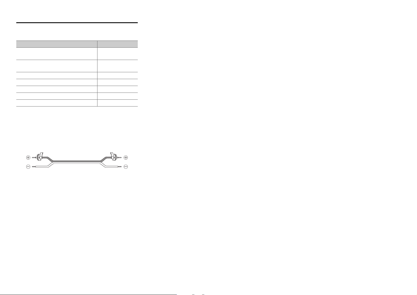
■ Screw-type speaker terminals
Strip 1/2" to 5/8" (12 to 15 mm) of insulation from the
ends of the speaker cables, and twist the bare wires
tightly, as shown.
■ Banana Plugs (North American models)
• If you are using banana plugs, tighten the speaker
terminal before inserting the banana plug.
• Do not insert the speaker code directly into the
center hole of the speaker terminal.
■ Speaker Connection Precautions
• You can connect speakers with an impedance of
between 4 and 16 ohms. If the impedance of any of
the connected speakers is 4 ohms or more, but less
than 6 ohms, be sure to set the minimum speaker
impedance to “4ohms” (➔ page 62). If you use
speakers with a lower impedance, and use the
amplifier at high volume levels for a long period of
time, the built-in protection circuit may be activated.
• Unnecessarily long, or very thin speaker cables may
affect the sound quality and should be avoided.
• Be careful not to short the positive and negative
wires. Doing so may damage the AV receiver.
Before connecting the power cord, connect all of
your speakers and AV components. A setup wizard
is launched upon first-time use to let you perform
the settings (➔ page 23).
1/2" to 5/8" (12 to 15 mm)
Connections
En-15
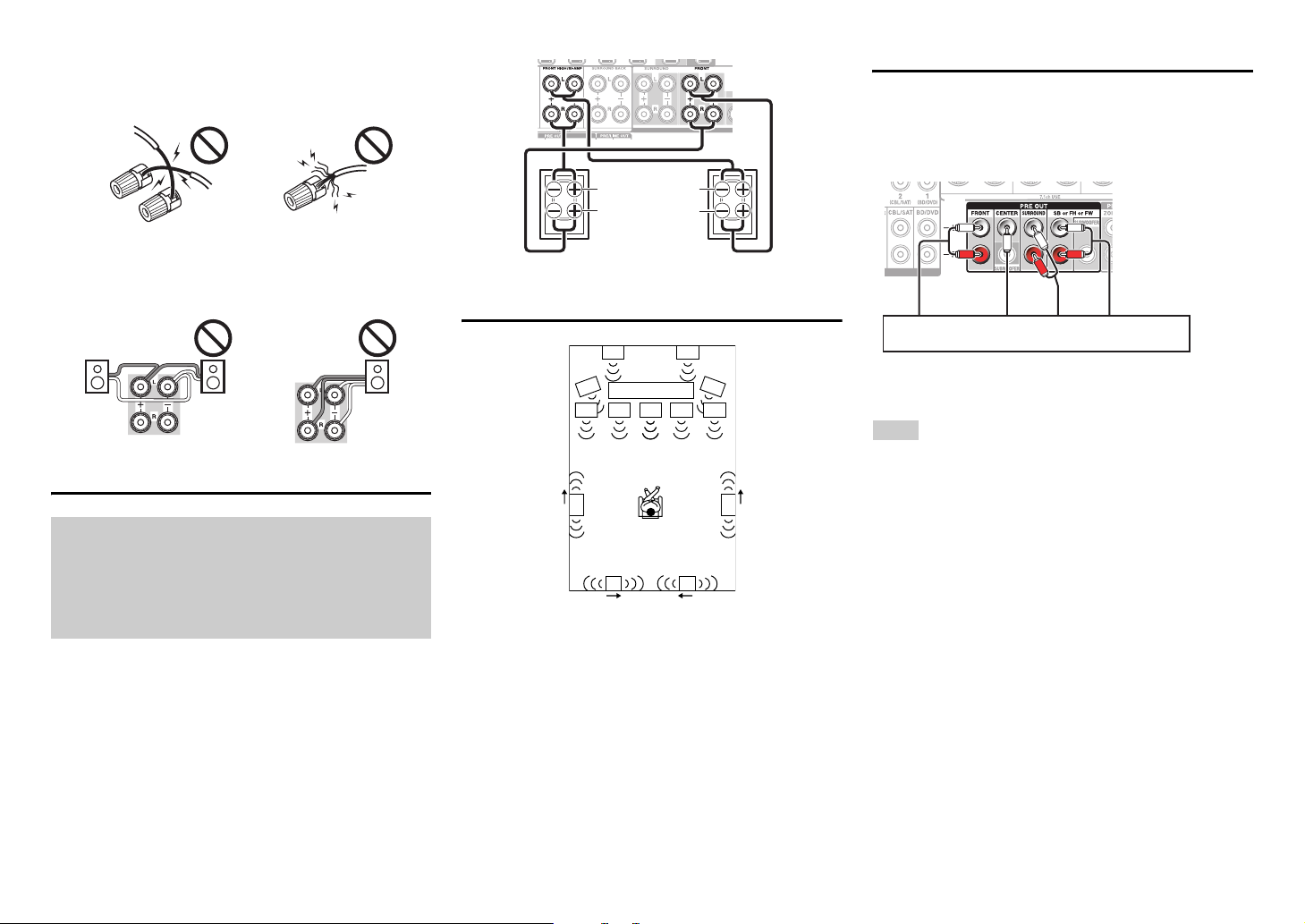
• Make sure the metal core of the wire does not have
contact with the AV receiver’s rear panel. Doing so
may damage the AV receiver.
• Don’t connect more than one cable to each speaker
terminal. Doing so may damage the AV receiver.
• Don’t connect one speaker to several terminals.
Bi-amping the Front Speakers
Bi-amping provides improved bass and treble
performance.
When bi-amping is used, the AV receiver is able to
drive up to a 5.1 speaker system in the main room.
Perform bi-amping connections by using FRONT
terminals and FRONT HIGH/Bi-AMP terminals as
shown below.
Once you’ve completed the bi-amping connections
and turned on the AV receiver, you must set the
speaker setting to enable bi-amping (➔ page 62).
Using Dipole Speakers
You can use dipole speakers for the surround and
surround back speakers. Dipole speakers output the
same sound in two directions.
Dipole speakers typically have an arrow printed on
them to indicate how they should be positioned. The
surround dipole speakers (a) should be positioned so
that their arrows point toward the TV/screen, while
the surround back dipole speakers (b) should be
positioned so that their arrows point toward each
other, as shown.
Connecting a Power Amplifier
You can use the AV receiver as a preamp. Connect
all speaker outputs to the power amplifier. See the
manuals supplied with your amplifier for details.
SB···Surround Back, FH···Front High, FW···Front
Wide
Note
• Specify “None” for any channel that you don’t want to
output (➔ page 62).
Important:
• When making the bi-amping connections, be sure to
remove the jumper bars that link the speakers’ tweeter
(high) and woofer (low) terminals.
• Bi-amping can be used only with speakers that support
bi-amping. Refer to your speaker manual.
Front right Front left
Woofer (low)
Tweeter (high)
bb
a a
TV/screen
L
R
Power amplifier

Connections
En-16
If you select the input selector button, the signal from
the component connected to the assigned jack is
played.
• Before making any AV connections, read the
manuals supplied with your AV components.
• Push plugs in all the way to make good connections
(loose connections can cause noise or
malfunctions).
• To prevent interference, keep audio and video
cables away from power cords and speaker cables.
Connections
Connecting the TV/AV components
Before connecting the power cord, connect all of your speakers and AV components. To display the setup
menu on the TV screen, connecting the TV to HDMI OUT MAIN is required.
ABCDEHGF
J
I
BC
DE
K
Input selector
buttons
A
Use this jack to connect to the HDMI input of the
TV. If your TV doesn’t support Audio Return
Channel (ARC)
*1
, you need to connect an optical
digital cable together with the HDMI cable to jack
F.
Another TV can be connected to the HDMI OUT
SUB jack.
*1
ARC is the function that carries the audio signal
from the TV to jack A. With ARC, a single HDMI
cable can connect the TV and the AV receiver.
B
Use this jack to connect to your Blu-ray Disc/DVD
player, etc.
C
Use this jack to connect to the Satellite/cable set-
top box, etc.
D
Use this jack to connect to the set top box/digital
video recorder, etc.
Tip
• To listen to the audio of a component connected via HDMI
through your TV’s speakers, enable “HDMI Through”
(
➔ page 74) and set the AV receiver to standby mode.
• In the case of Blu-ray Disc/DVD players, if no sound is
output despite following the above-mentioned procedure,
set your Blu-ray Disc/DVD player’s HDMI audio settings to
PCM.
• Connect a turntable (MM) that has a built-in phono preamp
to TV/CD IN, or connect it to PHONO IN with the phono
preamp turned off. If your turntable (MM) doesn’t have a
phono preamp, connect it to PHONO IN. If your turntable
has a moving coil (MC) type cartridge, you’ll need a
commercially available MC head amp or MC transformer to
connect to PHONO IN. See your turntable’s manual for
details.
If your turntable has a ground wire, connect it to the AV
receiver’s GND screw. With some turntables, connecting
the ground wire may produce an audible hum. If this
happens, disconnect it.
E
Use this jack to connect to the game consoles,
etc.
G
Use this port to connect to a LAN port on a router
so the AV receiver can be connected to your
home network.
H
Use jack and terminal here to connect the
supplied FM antenna and AM loop antenna.
I
Use this jack to make connections using an
analog audio cable.
With this connection, you can also enjoy analog
audio from external components while you are in
Zone 2/3.
J
Use this jack to make connections using a
component video cable.
K
Use this jack to connect to the camcorder/MHL-
enabled mobile device, etc.
Connections
En-17
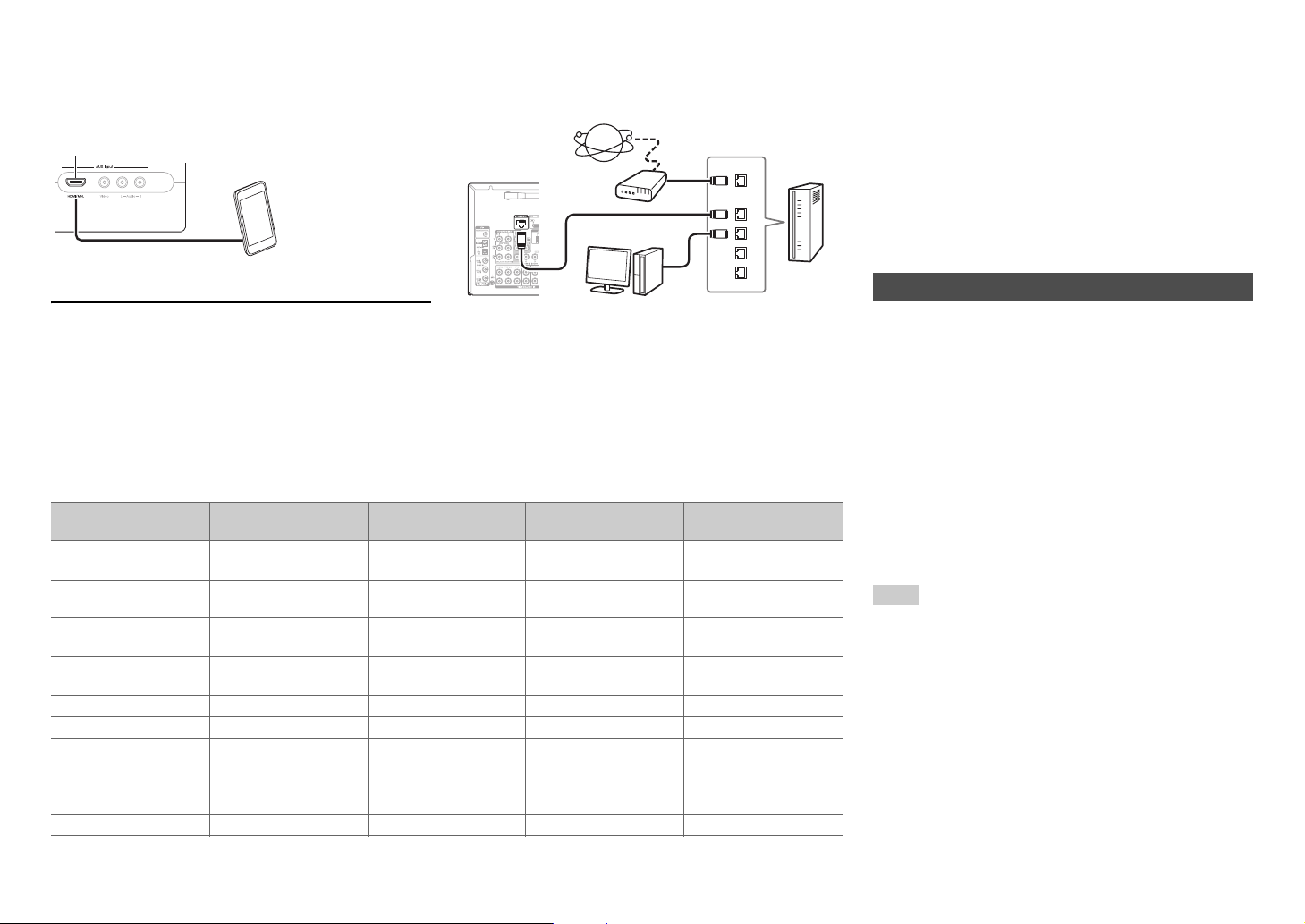
■ MHL (Mobile High-Definition Link)
With its support for MHL (Mobile High-Definition Link),
the AUX (Front) input allows you to deliver high-
definition video from a connected mobile device.
Connecting to the Network (Optional)
The following diagram shows how you can connect
the AV receiver to your home network. In this
example, it’s connected to a LAN port on a router,
which has a 4-port 100Base-TX switch built-in.
Network connection by wireless LAN is possible. See
“Performing Wireless LAN Setup” for connections
(➔ page 28).
Do not connect the AV receiver’s USB port to a USB
port on your computer. Music on your computer
cannot be played through the AV receiver in this way.
The default of the assignment for the input selector buttons and jacks are as shown below. These settings can
be changed. (The assignment for the AUX Input Video jack, analog audio jacks, and
HDMI AUX Input jack
cannot be changed.)
K
MHL-enabled mobile
device, etc.
WAN
LAN
Internet radio
Modem
Computer or media server
Router
Input selector buttons HDMI jacks COMPONENT VIDEO
jacks
DIGITAL IN COAXIAL
and OPTICAL jacks
Composite video and
analog audio jacks
BD/DVD HDMI IN 1 COMPONENT VIDEO
IN 1
DIGITAL IN
COAXIAL 1
VIDEO IN 1/AUDIO IN
BD/DVD
CBL/SAT HDMI IN 2 COMPONENT VIDEO
IN 2
DIGITAL IN
COAXIAL 2
VIDEO IN 2/AUDIO IN
CBL/SAT
STB/DVR HDMI IN 3 DIGITAL IN
COAXIAL 3
VIDEO IN 3/AUDIO IN
STB/DVR
Game 1 HDMI IN 4 DIGITAL IN
OPTICAL 1
VIDEO IN 4/AUDIO IN
GAME 1
Game 2 HDMI IN 5
PC HDMI IN 6 AUDIO IN PC
AUX HDMI AUX Input AUX Input
Video/Audio
TV/CD DIGITAL IN
OPTICAL 2
AUDIO IN TV/CD
Phono AUDIO IN PHONO
p
The AV receiver allows interoperability of the CEC
(Consumer Electronics Control) specified in the HDMI
standard, which is known as RIHD. Various linked
operations can be performed by connecting the AV
receiver to an RIHD-compatible TV, player, or
recorder.
Default setting is set to off, so it is required to change
the setting to on.
Perform this setting after the initial setup.
The following components are p-compatible
(As of January 2013).
■ TV
•Sharp TV
■ Players/Recorders
• Onkyo and Integra p-compatible players
• Toshiba players and recorders
• Sharp players and recorders (only when used
together with Sharp TV)
*
Models other than those mentioned above may have some
interoperability if compatible with CEC, which is part of the
HDMI Standard, but operation cannot be guaranteed.
Note
• For proper linked operations, do not connect more
p-compatible components than the quantities
specified below, to the HDMI input terminal.
– Blu-ray Disc/DVD players: up to three.
– Blu-ray Disc/DVD recorders/Digital Video Recorders: up
to three.
– Cable/Satellite Set-top boxes: up to four.
• Do not connect the AV receiver to another AV receiver/AV
amplifier via HDMI.
• Proper linked operations are not guaranteed when more
p-compatible components than the above-
mentioned quantities are connected.
About RIHD-compatible components

Connections
En-18
■ For p-compatible TV
The following linked operations are enabled by
connecting the AV receiver to an p-compatible
TV.
• The AV receiver will enter standby mode when the
TV is set to standby.
• You can set on the menu screen of the TV to either
output the audio from the speakers connected to the
AV receiver, or from the speakers of the TV.
• It is possible to output the audio coming from the
tuner or auxiliary input of your TV to the speakers of
the AV receiver. (A connection such as an optical
digital cable or similar is required in addition to the
HDMI cable.)
• Input to the AV receiver can be selected with the
remote controller of the TV.
• Operations such as volume adjustment or similar for
the AV receiver can be performed from the remote
controller of the TV.
■ For p-compatible players/recorders
The following linked operations are enabled by
connecting the AV receiver to an p-compatible
player/recorder.
• When playback is started on the player/recorder, AV
receiver will switch to the HDMI input of the
player/recorder that is playing back.
• Operation of the player/recorder is possible using
the remote controller supplied with the AV receiver.
*
Depending on the model used, not all operations may be
available.
Note
• Do not assign an HDMI IN to the TV/CD selector at this
time, otherwise appropriate CEC (Consumer Electronics
Control) operation will not be guaranteed.
1. Turn on the power for all connected components.
2. Turn off the power of the TV, and confirm that the
power of the connected components is turned off
automatically with the link operation.
3. Turn on the power of the Blu-ray Disc/DVD
player/recorder.
4. Start playback on the Blu-ray Disc/DVD
player/recorder, and verify the following:
• The AV receiver automatically turns on, and
selects the input to which the Blu-ray Disc/DVD
player/recorder is connected.
• The TV automatically turns on, and selects the
input to which the AV receiver is connected.
5. Following the operating instructions of the TV,
select “Use the TV speakers” from the menu
screen of the TV, and confirm that the audio is
output from the speakers of the TV, and not from
the speakers connected to the AV receiver.
6. Select “Use the speakers connected from the AV
receiver” from the menu screen of the TV, and
confirm that the audio is output from the speakers
connected to the AV receiver, and not from the TV
speakers.
Note
• Audio from DVD-Audio or Super Audio CD may not output
from the TV speakers. You will be able to output the audio
from the TV speakers by setting the audio output of the
DVD player to 2ch PCM. (It may not be possible depending
on the player models.)
• Even if you set to output audio on the TV speakers, audio
will be output from the speakers connected to the AV
receiver when you adjust the volume or switch the input on
the AV receiver. To output audio from the TV speakers, re-
do the corresponding operations on the TV.
• In case of an p connection with u and u audio
control compatible components, do not connect the u
cable at the same time.
• On the TV, when you select anything other than the HDMI
jack to which the AV receiver is connected, the input on the
AV receiver will be switched to “TV/CD”.
• The AV receiver will automatically power on in conjunction
when it determines it to be necessary. Even if the AV
receiver is connected to an p compatible TV or
player/recorder, it will not power on if it is not necessary. It
may not power on in conjunction when the TV is set to
output audio from the TV.
• Linked functions with the AV receiver may not work
depending on the component model connected. In such
cases, operate the AV receiver directly.
The video and audio signal flow
Connect the AV receiver between the AV
components and the TV. The signal from the AV
components is carried through the AV receiver. You
can enjoy the audio of the TV through the AV
receiver.
Video components can be connected by using any
one of the following video connection formats:
composite video, component video, or HDMI, the
latter offering the best picture quality.
Video input signals flow through the AV receiver as
shown, with composite video and component video
sources all being upconverted for the HDMI output(s).
Operations that can be performed with
RIHD connection
Confirm the settings
Connection Tips
Blu-ray Disc/DVD player, etc.
AV receiver
TV, projector, etc.
Audio
Video, audio
Video, audio
Connections
En-19
The composite video and component video outputs
pass through their respective input signals as they
are.
Note
• In order for the AV receiver to upconvert component input
to HDMI output, the source output must be set to 480i/576i.
When signal is input at resolution of 480p/576p and more,
error message will be displayed.
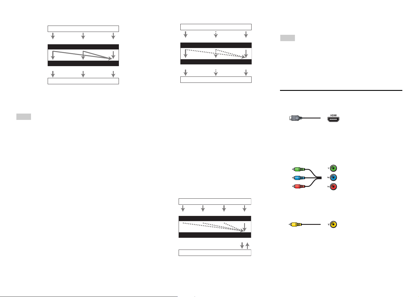
■ Signal Selection
If signals are present at more than one input, the
inputs will be selected automatically in the following
order of priority: HDMI, component video, composite
video.
However, for component video only, regardless of
whether a component video signal is actually present,
if a component video input is assigned to the input
selector, that component video input will be selected.
And if no component video input is assigned to the
input selector, this will be interpreted as no
component video signal being present.
In the Signal Selection Example shown below, video
signals are present at both the HDMI and composite
video inputs. However, the HDMI signal is
automatically selected as the source and the video is
output by the HDMI outputs.
• For optimal video performance, THX recommends
that video signals pass through the system without
upconversion (e.g., component video input passing
through to component video output).
• To by-pass the upconversion, set the “Picture
Mode” setting to “Bypass” (➔ page 69).
Audio components can be connected by using any of
the following audio connection formats: analog,
optical, coaxial, or HDMI.
When choosing a connection format, bear in mind
that the AV receiver does not convert digital input
signals for analog line outputs and vice versa.
If signals are present at more than one input, the
inputs will be selected automatically in the following
order of priority: HDMI, digital, analog.
*1
Depends on the “Audio TV Out (Main)” or “Audio TV
Out (Sub)” setting (➔ pages 74, 75).
*2
This is possible when “Audio Return Channel” is set to
“Auto” (➔ page 75), the TV/CD input selector is
selected, and your TV is ARC capable.
Tip
• When a signal is input via HDMI and the corresponding
input selector is selected, the HDMI indicator lights. In the
case of an optical or coaxial connection, the DIGITAL
indicator lights. If the analog audio is output, or if neither
HDMI nor digital signal inputs are assigned, ANALOG
indicator lights.
AV Cables and Jacks
■ HDMI
HDMI connections can carry digital video and audio.
■ Component video
Component video separates the luminance (Y) and
color difference signals (P
B, PR), providing the best
picture quality (some TV manufacturers label their
component video sockets slightly differently).
■ Composite video
Composite video is commonly used on TVs, DVDs,
and other video equipment.
IN
MONITOR OUT
Blu-ray Disc/DVD player, etc.
AV receiver
TV, projector, etc.
Composite
Composite
Component
Component
Video Signal Flow Chart
HDMI
HDMI
IN
MONITOR OUT
Blu-ray Disc/DVD player, etc.
TV, projector, etc.
Composite
Composite
Component
Component
Signal Selection Example
HDMI
HDMI
AV receiver
IN
OUT
Blu-ray Disc/DVD player, etc.
AV receiver
TV, projector, etc.
HDMICoaxial Analog
Audio Signal Flow Chart
HDMI
Optical
*1
*1 *1
*1 *2
Green
Blue
Red
Yellow
Y
C
B
/P
B
C
R
/P
R
Connections
En-20
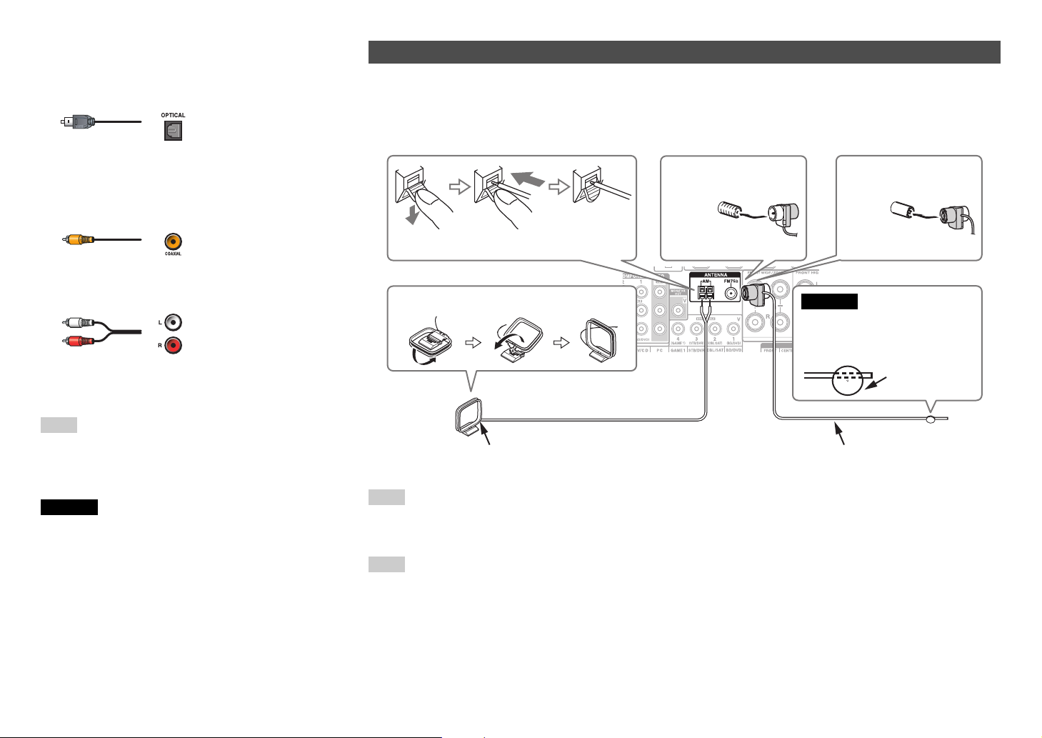
■ Optical digital audio
Optical digital connections allow you to enjoy digital
sound such as PCM
*1
, Dolby Digital or DTS. The
audio quality is the same as coaxial.
■ Coaxial digital audio
Coaxial digital connections allow you to enjoy digital
sound such as PCM
*1
, Dolby Digital or DTS. The
audio quality is the same as optical.
■ Analog audio (RCA)
Analog audio connections (RCA) carry analog audio.
*1
For PCM signals, the supported sampling rates are
32/44.1/48/88.2/96 kHz. With HDMI connections, 176.4
and 192 kHz are also supported.
Note
• The AV receiver does not support SCART plugs.
• The AV receiver’s optical digital jacks have shutter-type
covers that open when an optical plug is inserted and close
when it’s removed. Push plugs in all the way.
Caution
• To prevent shutter damage, hold the optical plug
straight when inserting and removing.
Orange
White
Red
This section explains how to connect the supplied indoor FM antenna and AM loop antenna.
The AV receiver won’t pick up any radio signals without any antenna connected, so you must connect the
antenna to use the tuner.
Note
• Once your AV receiver is ready for use, you’ll need to tune into a radio station and position the antenna to achieve the best
possible reception.
• Keep the AM loop antenna as far away as possible from your AV receiver, TV, speaker cables, and power cords.
Tip
• If you cannot achieve good reception with the supplied indoor FM antenna, try a commercially available outdoor FM antenna
instead.
• If you cannot achieve good reception with the supplied indoor AM loop antenna, try using it with a commercially available
outdoor AM antenna.
Connecting the Antennas
Thumbtacks, etc.
Insert the plug fully
into the jack.
Insert the plug fully
into the jack.
(North American
models)
(Australian models)
Push. Insert wire. Release.
Assembling the AM loop antenna
Indoor FM antenna (supplied)AM loop antenna (supplied)
Caution
• Be careful not to injure
yourself when using
thumbtacks.
Connections
En-21
With u (Remote Interactive), you can use the
following special functions:
■ System On/Auto Power On
When you start playback on a component connected
via u, while the AV receiver is on standby, the AV
receiver will automatically turn on and select that
component as the input source.
■ Direct Change
When playback is started on a component connected
via u, the AV receiver automatically selects that
component as the input source.
■ Remote Control
You can use the AV receiver’s remote controller to
control your other u-capable Integra/Onkyo
components, pointing the remote controller at the AV
receiver’s remote control sensor instead of the
component. You must enter the appropriate remote
control code first (➔ page 83).
Note
• Use only u cables for u connections. u cables are
supplied with Integra/Onkyo components.
• Some components have two u jacks. You can connect
either one to the AV receiver. The other jack is for
connecting additional u-capable components.
• Connect only Integra/Onkyo components to u jacks.
Connecting other manufacturer’s components may cause a
malfunction.
• Some components may not support all u functions. Refer
to the manuals supplied with your Integra/Onkyo
components.
• While Zone 2/3 is on, the System On/Auto Power On and
Direct Change u functions do not work.
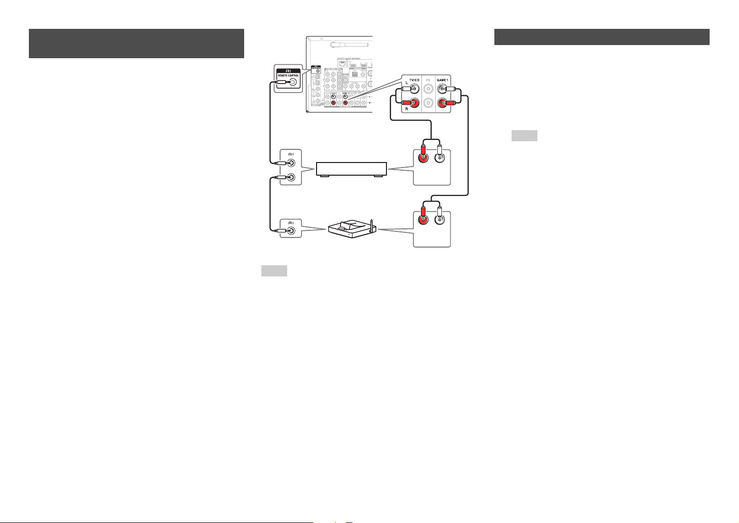
Connecting Integra/Onkyo RI
Components
1
Make sure that each Integra/Onkyo component
is connected with an analog audio cable
(connection
I in the hookup examples)
(➔ page 16).
2
Make the u connection (see the illustration).
3
If you’re using an RI Dock, or cassette tape
deck, change the Input Display (➔ page 51).
L R
ANALOG
AUDIO OUT
L R
ANALOG
AUDIO OUT
e.g., cassette tape deck
RI Dock
Using Headphones
1
Connect a pair of stereo headphones with a
standard plug (1/4 inch or ø
6.3 mm) to the
Phones jack.
While the headphones plug is inserted in the
Phones jack, = indicator, speaker/channel
indicator FL and FR lights.
Note
• Always turn down the volume before connecting your
headphones.
• While the headphones plug is inserted in the Phones
jack, the speakers are turned off. (The Zone 2/3
speakers are not turned off.)
• When you connect a pair of headphones, the listening
mode is set to Stereo, unless it’s already set to Stereo,
Mono, or Direct.

En-22
Turning On & Basic Operations
Turning On/Off the AV
Receiver
Note
• Before connecting the power cord, connect all of your
speakers and AV components.
• Turning on the AV receiver may cause a momentary power
surge that might interfere with other electrical equipment on
the same circuit. If this is a problem, plug the AV receiver
into a different branch circuit.
• Do not use a power cord other than the one supplied with
the AV receiver. The supplied power cord is designed
exclusively for use with the AV receiver and should not be
used with any other equipment.
• Never disconnect the power cord from the AV receiver
while the other end is still plugged into a wall outlet. Doing
so may cause an electric shock. Always disconnect the
power cord from the wall outlet first, and then the AV
receiver.
■ Smooth Operation in a Few Easy Steps
(Initial Setup)
To ensure smooth operation, here’s a few easy steps
to help you configure the AV receiver before you use
it for the very first time. These settings only need to
be made once. See “Initial Setup” for details
(➔ page 23).
Tip
• The Hybrid Standby indicator may light depending on the
status of settings (➔ page 23).
• For details on power management settings, see “Auto
Standby” (➔ page 75).
• If the HDMI Through setting is not set in standby mode, an
MHL-enabled mobile device cannot be charged even if it is
connected.
Turning On & Basic
Operations
Connecting the Power Cord
1
Connect the supplied power cord to the AV
receiver’s AC INLET.
2
Plug the power cord into an AC wall outlet.
To AC wall outlet
Turning On
1
Press 8On/Standby on the front panel.
or
Press Receiver followed by 8Receiver on the
remote controller.
The AV receiver comes on and its display lights.
Turning Off
1
Press 8On/Standby on the front panel.
or
Press Receiver followed by 8Receiver on the
remote controller.
The AV receiver will enter standby mode. To
prevent any loud surprises when you turn on the
AV receiver, always turn down the volume before
you turn it off.

Turning On & Basic Operations
En-23
When a new version of the firmware is available, the
notification window “Firmware Update Available”
pops up. This notification only appears when the AV
receiver is connected to the Internet (➔ pages 17,
28). To perform the firmware update, follow the
instructions on screen.
Use q/w and Enter on the AV receiver or remote
controller to select one of the options.
` Update Now:
Starts the firmware update.
Refer to “Firmware Update” (➔ page 99).
` Remind me Later:
The update notification will pop up again the
next time you turn the AV receiver on.
` Never Remind me:
Disables the automatic update notification.
Tip
• The update notification window can be enabled or disabled
in “Update Notice” (➔ page 77).
By way of optimized circuitry, this function reduces
power consumption when the AV receiver is in
standby mode. The Hybrid Standby indicator will
light in either of the following conditions:
–“HDMI Through” is enabled (the HDMI indicator is
off).
–“Network Standby” is enabled (the NET indicator
is off).
Note
• If Zones are turned on or, if a mobile device connected to
the Front Input (MHL) is charging, the Hybrid Standby
indicator won’t light.
Initial Setup
This section explains the settings that we recommend
you to make before using the AV receiver for the very
first time. A setup wizard is launched upon first-time
use to let you perform those settings.
Tip
• The on-screen menus appear only on a TV that is
connected to HDMI OUT MAIN.
This step determines the language used for the on-
screen setup menus. See “Language” in “OSD
Setup” (➔ page 72).
Tip
• Pressing Home will close the setup wizard. To restart the
initial setup, select “Initial Setup” in the “Hardware Setup”
menu (➔ page 77).
After selecting the language for on-screen setup
menus, a welcome screen is displayed.
This step performs the automatic speaker setup.
Firmware Update Notification
About the Hybrid Standby indicator
Selecting the Language for the On-
screen Setup Menus
1st Step : Audyssey MultEQ: Auto Setup
2nd Step : Source Connection
3rd Step : Remote Mode Setup
4th Step : Network Connection
Yes
No
Welcome to initial setup. Have you connected all the speakers and devices?
Before starting, please connect speakers and sources.
Now, would you like to start initial setup?
Exit
Initial Setup
HOME
1
Use q/w on the AV receiver or remote
controller to select one of the following
options, and then press Enter.
` Yes:
Continues to “Audyssey MultEQ: Auto
Setup”.
` No:
Skips the settings and terminates the initial
setup. The setup wizard goes to
“Terminating the Initial Setup” (➔ page 24).
You can always restart the initial setup by
selecting “Initial Setup” in the “Hardware
Setup” menu (➔ page 77).
Audyssey MultEQ: Auto Setup
1
Use q/w to select one of the following options,
and then press Enter.
` Do it Now:
The automatic speaker setup is performed
following instructions on screen. Refer to
step 2 of “Using the Automatic Speaker
Setup” (➔ page 25). When this setting is
complete, the setup wizard continues to
“Source Connection”.
` Do it Later:
Skips this setting.
Press Enter and continue to “Source
Connection”.

Turning On & Basic Operations
En-24
This step checks the connection of source
components.
With this step, you can enter remote control codes for
the components you want to operate.
This step checks your network connection.
This step ends the initial setup process.
Source Connection
1
Use q/w to select one of the following options,
and then press Enter.
` Yes, Continue:
Performs the checkings.
` No, Skip:
Skips this step and continues to “Remote
Mode Setup”.
2
Select the input selector for which you want to
check the connection and press Enter.
The picture and sound of the corresponding
source should appear on screen with a
verification prompt.
3
When prompted, use q/w to select one of the
following options and then press Enter.
` Yes:
Confirms that the source is properly
displayed.
` No:
Displays an error report. Follow the
troubleshooting instructions and recheck the
source.
4
Use q/w to select one of the following options,
and then press Enter.
` Yes:
Returns to step 2.
` No, Done Checking:
The setup wizard continues to “Remote
Mode Setup”.
Remote Mode Setup
1
Use q/w to select one of the following options,
and then press Enter.
` Yes:
Performs the remote control code input.
Refer to step 5 of “Looking up for Remote
Control Codes” (➔ page 82).
` No, Skip:
Skips this step and continues to “Network
Connection”.
2
When you’re finished, select one of the
following options and press Enter.
` Yes, Done:
The setup wizard continues to “Network
Connection”.
` No, not yet:
You can enter other remote control codes.
Network Connection
1
Use q/w to select one of the following options,
and then press Enter.
` Yes:
Performs the checkings.
` No, Skip:
Skips this step and terminates the initial
setup.
2
Follow the instructions on screen to perform
the network checking.
The checking is complete when the message
“Successfully connected.” appears at the
middle of the screen. Press Enter to terminate
the initial setup.
Tip
• If you have selected “Wireless”, you need to perform
the wireless LAN setup. See “Performing Wireless
LAN Setup” (➔ page 28). This completes the initial
setup.
3
If an error message appears, select one of the
following options and press Enter.
` Retry:
Performs the checking again.
` No, Do it Later:
Skips this step and terminates the initial
setup. The setup wizard goes to
“Terminating the Initial Setup”.
Terminating the Initial Setup
1
Press Enter.
To restart the initial setup, select “Initial Setup”
in the “Hardware Setup” menu (➔ page 77).
Turning On & Basic Operations
En-25
With the supplied calibrated microphone,
Audyssey MultEQ
®
automatically determines the
number of speakers connected, their size for
purposes of bass management, optimum crossover
frequencies to the subwoofer (if present), and
distances from the primary listening position.
Audyssey MultEQ then removes the distortion caused
by room acoustics by capturing room acoustical
problems over the listening area in both the frequency
and time domain. The result is clear, well-balanced
sound for everyone. Audyssey MultEQ can be used
with Audyssey Dynamic EQ
®
and
Audyssey Dynamic Volume
®
(➔ page 67).
Before using this function, connect and position all of
your speakers.
Audyssey MultEQ offers two ways of measuring: the
“Audyssey Quick Start” and “Audyssey MultEQ
Full Calibration”.
•“Audyssey Quick Start” uses the measurement
from one position to perform the speaker setting
only.
•“Audyssey MultEQ Full Calibration” uses the
measurement from six positions to correct room
response in addition to the speaker setting.
The more positions are used in measuring, the better
the listening environment will become. We
recommend using a measurement from six positions
to create the best listening environment.
The Quick Start takes 2 minutes and Full Calibration
takes about 20 minutes.
Total measurement time varies depending on the
number of speakers.
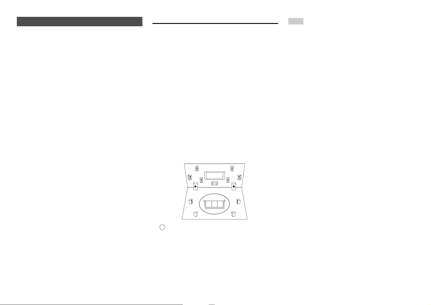
Measurement procedure
To create a listening environment in your home
theater that all listeners will enjoy, Audyssey MultEQ
takes measurements at up to six positions within the
listening area. Position the microphone at ear height
of a seated listener with the microphone tip pointed
directly at the ceiling using a tripod. Do not hold the
microphone in your hand during measurements as
this will produce inaccurate results.
■ First measurement position
Also referred to as the Main Listening Position, this
refers to the most central position where one would
normally sit within the listening environment.
Audyssey MultEQ uses the measurements from this
position to calculate speaker distance, level, and the
optimum crossover value for the subwoofer.
■ Second-sixth measurement positions
These are the other listening positions (i.e., the
places where the other listeners will sit). You can
measure up to six positions.
Note
• Make the room as quiet as possible. Background noise and
Radio Frequency Interference (RFI) can disrupt the room
measurements. Close windows, televisions, radios, air
conditioners, fluorescent lights, home appliances, light
dimmers, or other devices. Turn off the cell phone (even if
it is not in use) or place it away from all audio electronics.
• The microphone picks up test tones played through each
speaker as Audyssey MultEQ Room Correction and
Speaker Setup runs.
• Audyssey MultEQ Room Correction and Speaker Setup
cannot be performed while a pair of headphones is
connected.
Using the Automatic Speaker Setup
TV
ab
fed
c
: Listening area
ato f: Listening position

Turning On & Basic Operations
En-26
1
Turn on the AV receiver and the connected TV.
On the TV, select the input to which the AV
receiver is connected.
2
Set the speaker setup microphone at the Main
Listening Position a, and connect it to the
Setup Mic jack.
The speaker setting menu appears.
Note
• The on-screen menus appear only on a TV that is
connected to HDMI OUT MAIN. If your TV is
connected to other video outputs, use the AV
receiver’s display when changing settings.
3
When you’ve finished making the settings,
press Enter.
Perform the “2. Speaker Setup” according to your
speaker configuration:
– Speakers Type (Front) (➔ page 62)
– Powered Zone 2 (➔ page 62)
– Subwoofer (➔ page 62)
If you use a powered subwoofer(s), go to step 4.
If not, go to step 5.
Speaker setup microphone
Setup Mic jack
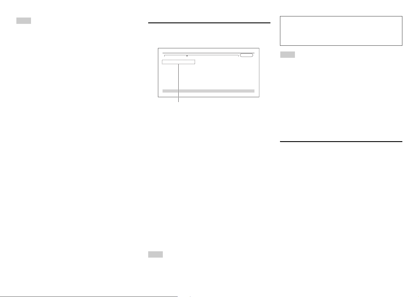
MultEQ: Auto Setup
AUDYSSEY
Speakers Type(Front)
Powered Zone 2
Subwoofer
Normal
No
Yes
4
Adjust the subwoofer volume level to 75 dB,
and then press Enter.
Test tones are played through the subwoofer.
Use the volume control on the subwoofer.
Note
• If your subwoofer does not have a volume control,
disregard the displayed level and press Enter to
proceed to the next step.
• If you set the subwoofer’s volume control to its
maximum and the level displayed is lower than 75 dB,
leave the subwoofer’s volume control at its maximum
and press Enter to proceed to the next step.
5
Use q/w to select “Audyssey Quick Start” or
“Audyssey MultEQ Full Calibration”, and then
press Enter.
6
Press Enter.
Audyssey MultEQ
®
Room Correction and
Speaker Setup starts.
Test tones are played through each speaker as
Audyssey MultEQ Room Correction and Speaker
Setup runs. This process takes a few minutes.
Please refrain from talking during
measurements and do not stand between
speakers and the microphone.
Do not disconnect the speaker setup microphone
during Audyssey MultEQ Room Correction and
Speaker Setup, unless you want to cancel the
setup.
If you select “Audyssey Quick Start”, you will go
to step 9.
7
Place the speaker setup microphone at the
next position, and then press Enter.
Audyssey MultEQ performs more
measurements. This takes a few minutes.
8
When prompted, repeat step 7.
9
Use q/w to select an option, and then press
Enter.
The options are:
` Save:
Save the calculated settings and exit
Audyssey MultEQ Room Correction and
Speaker Setup.
` Cancel:
Cancel Audyssey MultEQ Room Correction
and Speaker Setup.
Tip
• You can view the calculated settings for the speaker
configuration, speaker distances, and speaker levels
by using e/r.
10
Use q/w to select a target, and use e/r to
change the setting.
After the results of Audyssey MultEQ have been
saved, the menu will display the “Audyssey”
(➔ page 67), “Dynamic EQ” (➔ page 67),
“Dynamic Volume” (➔ page 67) settings.
Note
• When “Audyssey Quick Start” has been used for
measurement, “Audyssey” cannot be selected.
• These settings are applied to all input selectors.
11
Press Enter.
12
Disconnect the speaker setup microphone.
Save
Cancel
AUDYSSEY
MultEQ: Auto Setup
-- Review Speaker Configuration --
Subwoofer
Front
Center
Surround
Front Wide
Front High
Surround Back
Surround Back Ch
Yes
100Hz
40Hz
100Hz
None
None
120Hz
2ch
Turning On & Basic Operations
En-27
Note
• You can cancel Audyssey MultEQ
®
Room Correction and
Speaker Setup at any point in this procedure simply by
disconnecting the setup microphone.
• Do not connect or disconnect any speakers during
Audyssey MultEQ Room Correction and Speaker Setup.
• If the AV receiver is muted, it will be unmuted automatically
when Audyssey MultEQ Room Correction and Speaker
Setup starts.
• Changes to the room after Audyssey MultEQ Room
Correction and Speaker Setup requires you run
Audyssey MultEQ Room Correction and Speaker Setup
again, as room EQ characteristics may have changed.
Error Messages
While Audyssey MultEQ Room Correction and
Speaker Setup is in progress, one of the error
messages below may appear.
The options are:
` Retry:
Try again.
` Cancel:
Cancel Audyssey MultEQ Room Correction and
Speaker Setup.
• Ambient noise is too high.
The background noise is too loud. Remove the
source of the noise and try again.
• Speaker Matching Error!
The number of speakers detected was different
from that of the first measurement. Check the
speaker connection.
• Writing Error!
This message appears if saving fails. Try saving
again. If this message appears after 2 or 3
attempts, contact the dealer from whom you
purchased this unit.
• Speaker Detect Error
This message appears if a speaker is not detected.
“No” means that no speaker was detected.
Tip
• See “Speaker Configuration” for appropriate settings
(➔ page 12).
Note
• Please note that THX recommends any THX main
speakers be set to “80Hz(THX)”. If you set up your
speakers using Audyssey MultEQ Room Correction and
Speaker Setup, please make sure manually that any THX
speakers are set to “80Hz(THX)” crossover (➔ page 62).
• Sometimes due to the electrical complexities of subwoofers
and the interaction with the room, THX recommends setting
the level and the distance of the subwoofer manually.
• Sometimes due to interaction with the room, you may
notice irregular results when setting the level and/or
distance of the main speakers. If this happens, THX
recommends setting them manually.
Using a Powered Subwoofer
If you’re using a powered subwoofer and it outputs
very low-frequency sound at a low volume level, it
may not be detected by Audyssey MultEQ Room
Correction and Speaker Setup.
If the “Subwoofer” appears on the “Review Speaker
Configuration” screen as “No”, increase the
subwoofer’s volume to the half-way point, set it to its
highest crossover frequency, and then try running
Audyssey MultEQ Room Correction and Speaker
Setup again. Note that if the volume is set too high
and the sound distorts, detection issues may occur,
so use an appropriate volume level. If the subwoofer
has a low-pass filter switch, set it to Off or Direct.
Refer to your subwoofer’s instruction manual for
details.
Retry
Cancel
Ambient noise is too high.
AUDYSSEY
MultEQ: Auto Setup
Error message
The setup of the speaker can be done manually
(➔ page 62).
The setup of the volume level of each speaker also
can be done manually (➔ pages 63, 64).

Turning On & Basic Operations
En-28
To achieve a wireless network connection, it is
necessary to perform the wireless LAN setup. The
setup can be done either automatically or manually.
You use your AV receiver as a wireless client
(wireless terminal) and connect it to a PC or to the
Internet.
Automatic wireless LAN setup
Performing Wireless LAN Setup
A wireless LAN (WLAN) is a local area network that
relies on wireless communication.
To achieve a wireless network connection, you will
need the following component:
■ Access point
Also known as the base station, it links your AV
receiver (wireless client) with a PC or network.
Access points fall into two categories: the bridge
type that only performs data relay in a local area
network, or the router type that has a built-in router
functionality.
1
Press Receiver followed by Home.
2
Use e/r or q/w to select “Setup”, and then
press Enter.
3
Use q/w to select “Hardware Setup”, and then
press Enter.
4
Use q/w to select “Network”, and then press
Enter.
5
Use q/w to select “Network Connection”, and
e/r to select “Wireless”, and then press
Enter (➔ page 76).
The “Wireless Setup” menu is displayed on
screen.
Tip
• The same setting is available even if “Wireless” is
selected in “Network Connection” in initial setup
(➔ page 24).
6
Press q/w to select (North American models)
“Push Button Configuration (Other
Routers)”
*1
/(excluding North American
models) “Push Button Configuration (Select
from Router)”, and press Enter.
The method to make settings by “Push Button
Configuration” is displayed, providing the
following two options:
Tip
*1
(North American models) To connect to Linksys
E/EA Router, select “Push Button Configuration
(Linksys E/EA Router)” and make settings
following the instructions on the screen.
■ Push Button method
1. Use q/w to select “Push Button” and then
press Enter.
2. Press the WPS button on your Access Point
device.
Tip
• How long the WPS button should be pressed differs
depending on the type of Access Point device. Refer
to the instruction manual provided with your Access
Point device for operations.
■ PIN code method
1. Use q/w to select “PIN Code” and then press
Enter.
An 8-digit PIN code is displayed. The PIN
code is displayed scrolling on the AV
receiver’s display.
2. Input the provided code in your Access Point.
For information on the registration process,
please refer to the instruction manual
provided with your Access Point device.
7
Press Enter to confirm.
Connection to your Access Point starts and Wi-Fi
indicator flashes. After the connection to your
Access Point is completed, Wi-Fi indicator lights
and the connection status is displayed on the
screen.
This completes the wireless LAN setup.
You can review your setup with the “Status”
option on the “Wireless Setup” menu.
Note
• If Wi-Fi indicator doesn’t light, the connection to your
Access Point is not done successfully. Configure this
setting again (➔ page 94).

Turning On & Basic Operations
En-29
Manual wireless LAN setup
1
Press Receiver followed by Home.
2
Use e/r or q/w to select “Setup”, and then
press Enter.
3
Use q/w to select “Hardware Setup”, and then
press Enter.
4
Use q/w to select “Network”, and then press
Enter.
5
Use q/w to select “Network Connection”, and
e/r to select “Wireless”, and then press
Enter (➔ page 76).
The “Wireless Setup” menu is displayed on
screen.
Tip
• The same setting is available even if “Wireless” is
selected in “Network Connection” in initial setup
(➔ page 24).
6
Use q/w to select “Search Wireless Network”
and then press Enter.
A list of available Access Points is displayed.
Tip
• If Access Point you wish to connect to is not displayed
in the list of available Access Points, the setting also
can be made by entering “SSID”, “Security”, and
“Password” manually after selecting “Direct Input”.
7
Use q/w to select the Access Point you wish to
connect to, and then press Enter.
Depending on your encryption settings, the
security of your Access Point will provide one of
the following patterns:
■ WEP method
1. Use q/w to select “Default Key ID” and then
press Enter.
2. Use q/w to choose an ID between 1 and 4,
and then press Enter.
3. Use q/w to select “Password” and then press
Enter.
4. Use the keyboard on screen to enter the
password and confirm with “OK”.
■ WPA/WPA2 method
1. Use q/w to select “Password” and then press
Enter.
2. Use the keyboard on screen to enter the
password and confirm with “OK”.
■ No encryption
If your Access Point device is not secured by
encryption, there is no need to input any secret
key.
Tip
• When you select the Access Point you wish to connect to
from the list of available Access Points, “SSID” and
“Security” are automatically displayed. These settings can
be changed manually.
8
Select “OK” and press Enter.
Connection to your Access Point starts and Wi-Fi
indicator flashes. After the connection to your
Access Point is completed, Wi-Fi indicator lights
and the connection status is displayed on the
screen.
This completes the wireless LAN setup.
You can review your setup with the “Status”
option on the “Wireless Setup” menu.
Note
• If Wi-Fi indicator doesn’t light, the connection to your
Access Point is not done successfully. Configure this
setting again (➔ page 94).
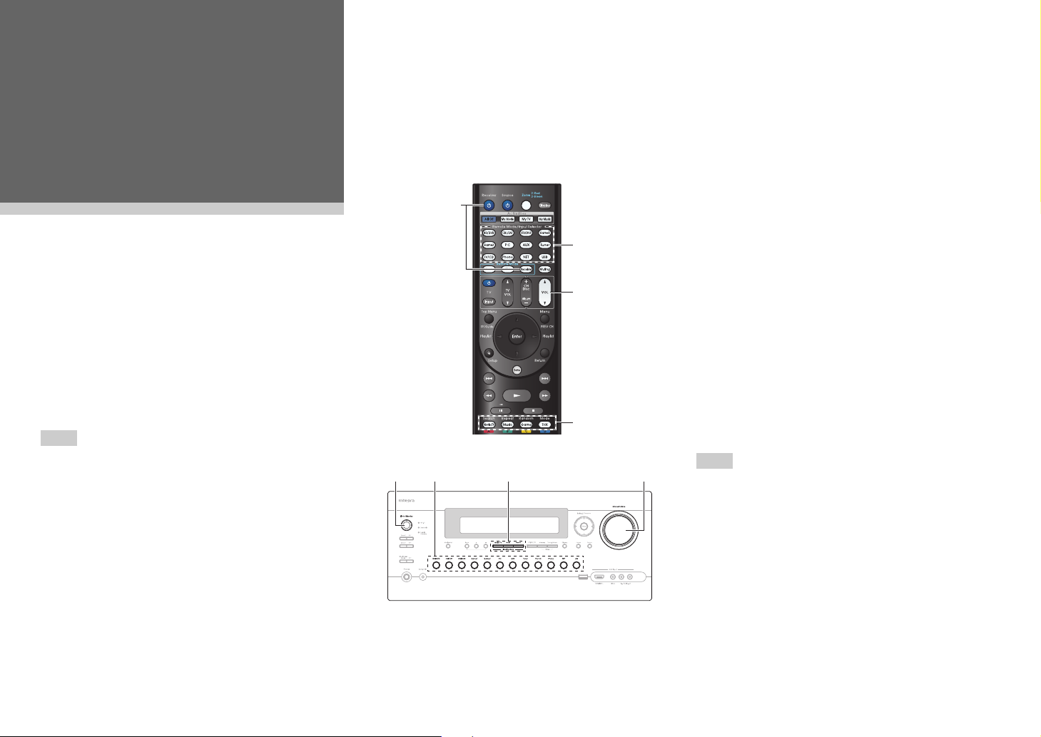
En-30
Playback
Playback
This section describes the basic operation such as
playback, listening mode, and other useful functions.
Reading this manual from the beginning to this
section helps you to understand the basic
connection/setup/operation.
■ Screen Saver
If there is no video signal on the current input source
and no operation for a specific time (three minutes by
default), a screen saver automatically comes on.
Tip
• The time until the screen saver activates itself can
be changed in the “Screen Saver” setting
(➔ page 72).
• The screen will return to its previous state if the AV
receiver is operated.
See also:
• “Playing an Audio from Bluetooth-enabled Device”
(➔ page 32)
• “Playing a USB Device” (➔ page 33)
• “Listening to TuneIn” (➔ page 33)
• “Registering Other Internet Radio” (➔ page 35)
• “Playing Music Files on a Server (DLNA)”
(➔ page 35)
• “Playing Music Files on a Shared Folder”
(➔ page 37)
• “Remote Playback” (➔ page 38)
• “Listening to AM/FM Radio” (➔ page 39)
• “Playing Audio and Video from Separate Sources”
(➔ page 41)
• “Controlling Other Components” (➔ page 82)
• “Using the Integra/Onkyo Dock” (➔ page 87)
Tip
• When listening to an HDMI component through the AV
receiver, set the HDMI component so that its video can be
seen on the TV screen (on the TV, select the input of the
HDMI component connected to the AV receiver). If the TV
power is off or the TV is set to another input source, this
may result in no sound from the AV receiver or the sound
may be cut off.
Playback
4
3
2
1
1432
1
Turn on the AV receiver, the TV and the AV
components.
* When you operate the AV receiver with the remote
controller, press the Receiver button first.
2
Select the input on the AV receiver to play the
AV components.
Press the input selector button to which the AV
components to be played is connected.
Press the TV/CD button to play the audio of the
TV. Switching the input on the TV is also
required. Select the input to which the AV
receiver is connected by using the TV remote
controller.
* For the CEC compatible TV and the AV components
connected with HDMI connections, switching the input
is automatically performed. Switch the input manually
for other AV components.
3
Select the desired listening mode.
You can enjoy various types of listening mode.
The listening mode is switched by pressing
Listening mode button on the AV receiver or the
remote controller.
4
Adjust the volume.
You can enjoy the surround sound.
Loading...