


DTR-60.6
Basic Manual
Advanced Manual found here
http://integraworldwide.com/manual/dtr606/adv/en.html
En

Before Start
About the Basic Manual
The Basic Manual leads you through the fundamental steps to enjoy the AV Receiver from connections to TV, speaker system and playback components, to necessary functions for playback. As well as that, Basic Manual informs you with the instructions on frequently used functions. Besides, there is another part of the manual called Advanced Manual to inform you with more detailed information, which we have decided to publish on the web from the ecological point of view.
Advanced Manual
Advanced Manual is always updated with the latest information and its user friendly interface, which does not matter whether you access from PC or Smartphone, helps you to understand more deeply about the AV Receiver. Advanced Manual is consisted of the following chapters. r Details on AM/FM Playback
r Playing Music Files on a USB Storage Device r Listening to Internet Radio
r Playing Music with DLNA
r Playing Music Files in a Shared Folder
r Operating Music Files with the Remote Controller r Listening Mode
r Advanced Settings
r Operating Other Components with the Remote Controller r Advanced Connection
r Connecting and Operating Onkyo RI Components r Control Function between the Unit and External
Component
r Firmware Update r Troubleshooting
r Reference Information
Advanced Manual found here
http://integraworldwide.com/manual/dtr606/adv/en.html
Features
r Equipped with 9 channel amplifier
r Supports playback in Dolby Atmos format which provides 360-degree placement and movement of sounds including overhead sound
r Dolby Surround listening mode expands 2 ch, 5.1 ch or 7.1 ch source to available speaker configurations
r THX Select2 Plus certified
r Incorporates Qdeo™ technology for HDMI video upscaling
r All HDMI jacks support displays of 4K resolution at 60 Hz r Supports the HDMI Through function which allows
transmission from playback devices to the TV in standby state
r Supports HDCP2.2, a strict copy-protection for providing high quality content (HDMI IN3/OUT MAIN only)
r Supports ARC (Audio Return Channel) r Supports USB storage playback
r Supports variety of network functions such as Internet Radio, DLNA, etc.
r Supports MHL-enabled mobile device r Bi-Amping capability
r A/V Sync function to correct deviation of audio and video r Multi-zone function which allows you to play a different source in another room from the main room (Video can
also be played in Zone 2)
r 32 bit DSP (Digital Signal Processor) with excellent calculation performance
r Music Optimizer™ for Compressed Digital Music files r Phase Matching Bass System
r Automatic speaker setup available using supplied calibrated microphone (AccuEQ Room Calibration)
r Supports playback of MP3, FLAC, WAV, Ogg Vorbis, Apple Lossless, DSD via network and USB storage device (the supported formats will differ depending on the use environment)
r ISF (Imaging Science Foundation) Video Calibration
Supplied Accessories
|
|
|
|
|
Indoor FM antenna |
--- (1) |
|
|
|
|
|
|
AM loop antenna --- |
(1) |
|
|
|
|
|
|
Color labels for speaker cable |
(1) |
|
|
|
|
|
|
|||
|
|
|
|
|
Remote controller (RC-883M) |
(1) |
|
|
|
|
|
|
|||
|
|
|
|
|
Batteries (AA/R6) --- |
(2) |
|
|
|
|
|
|
Power cord --- (1) |
|
|
|
|
|
|
|
Speaker setup microphone --- |
(1) |
|
¼The number in parenthesis indicates the quantity. On packaging, the letter at the end of the product name indicates the color.
How to use the remote controller
Remote control sensor
AV Receiver
Batteries (AA/R6)
About
|HV O
¼If you do not use the remote controller for a long time, remove the batteries to prevent leakage.
¼Note that keeping consumed batteries inside may cause corrosion resulting in damage of the remote controller.
2

Step 1: Connections
Personal computer
HDMI
OUT
HDMI cable
HDMI
OUT
Game console |
|
|
|
|
|
|
|
|
|
Set-top box/Digital |
|
|
|
|
|
|
video recorder, etc. |
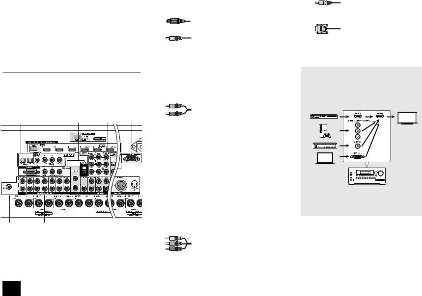
1 Connecting the TV and players
Important: The power cord must be connected only after all other connections are completed.
HDMI Cable Connection
The unit has many HDMI jacks on its rear panel and each of them corresponds to an input selector button of the same name on the front panel. For example, a Blu-ray Disc player will be connected to the IN 1 jack and the BD/DVD button on the front panel will be used to listen to the playback sound (if the player is CEC compliant, input will be switched automatically). If you add another Blu-ray Disc player, you can use any other jack than IN 1. It is possible to change assignment of the input jacks and input selector buttons.
HDMI |
HDMI |
OUT |
OUT |
Satellite/Cable set-top box, etc.
TV
HDMI
IN
To use the ARC function, connect to the ARC compatible HDMI jack of the TV and make an appropriate setting on the unit. See "2nd Step : Source Connection" of "Step 2: Setting Up".
HDMI
OUT
Blu-ray Disc/DVD player
For how to make settings, see the Advanced Manual.
To connect the TV and the unit, connect the HDMI OUT MAIN jack of the unit and the HDMI IN jack of the TV using an HDMI cable. With this connection, it becomes possible to display the setting screen of the unit on the TV or transmit video/ audio signals from the player to the TV. If your TV supports ARC (Audio Return Channel), it is possible to play the TV sound with the AV receiver's speakers with this connection only. If your TV does not support ARC, you need, in addition to the HDMI OUT MAIN jack connection, a digital optical cable connection between the digital audio out optical jack of the TV and the DIGITAL IN OPTICAL jack of the unit or an analog audio (RCA) cable connection between the audio output jack of the TV and the TV/CD analog audio input jack of the unit.
z Audio connection with a TV not supporting ARC
¼ Select an appropriate connection for your TV.
TV
AUDIO
OUT
DIGITAL
OPTICAL
OUT
Another TV can be connected to the HDMI OUT SUB jack. In this case, press Monitor Out on the main unit several times to display "SUB" or "MAIN+SUB" and select the output method. You can also enjoy using Zone function with the HDMI OUT ZONE 2 jack. For details, see the section 6
"Using the multi-zone function" of "Step 3: Playing Back".
3
The unit supports the HDMI Through function that allows transmission from players to the TV even if the unit is in standby. You have to modify the settings to enable the input selection link with CEC compliant device, connection with ARC compatible TV, and HDMI Through function. See "2nd Step : Source Connection" of "Step 2: Setting Up".
r To enjoy HDCP2.2 protected video, connect the player to the IN3 jack and the TV to the HDMI OUT MAIN jack of the unit. Your player and TV need to support HDCP2.2.
r To play 4K or 1080p video, use the high speed HDMI cable. r It is possible to send video and audio of an MHL-enabled
mobile device by connecting the MHL-enabled mobile device to the AUX Input HDMI/MHL jacks on the front panel.
Connecting Components without HDMI
If your AV component does not have HDMI jack, use an available jack of your component for cable connection with this unit. Just as the HDMI jacks, other jacks on this unit have a preassigned input selector button on the front panel. See the name of the input selector button shown with the jack when connecting the device.
1 |
5 |
4 |
6 |
32
Audio signal connection
1 Digital connection: Use a digital optical cable (OPTICAL) or digital coaxial cable (COAXIAL) for connection with a player.
Digital optical cable (OPTICAL)
¼ As the digital in optical jack of the unit has a cover, push in the cable against the cover as it is turned inside.
Digital coaxial cable (COAXIAL)
2 Analog connection: Use an analog audio (RCA) cable for connection with a player.
To enjoy multi-zone playback of audio of a CD player or such other player without HDMI output jack, you need to use the analog audio (RCA) cable to connect the corresponding jacks of the player and this unit. For details on the multi-zone function, see the section 6 "Using the multi-zone function" of "Step 3: Playing Back".
Analog audio (RCA) cable
3 Connection with turntable: If it uses an MM type cartridge and does not have a built-in audio equalizer, connect it to the 3 PHONO jack. If the connected turntable has a built-in audio equalizer, connect it to the 2 TV/CD jack.
¼If it uses an MC type cartridge, install an audio equalizer compatible with MC type cartridge between the unit and the turntable by connecting it to the 2 TV/CD jack. For details, refer to the turntable's instruction manual.
¼If the turntable has a ground wire, connect it to the GND terminal of this unit. If connecting the ground wire increases noise, disconnect it.
Video signal connection
The unit has a video upconversion function. For details, see the section on the right.
4 Use a component video cable to connect a TV with component video input jacks and a player with component video output jacks.
Component video cable
¼ Its transmitted video has higher quality than that of composite video cable.
Step 1: Connections
5 Use a composite video cable to connect a TV with composite video input jack or a player with composite video output jack.
Composite video cable
6 Use an analog RGB cable to connect the unit with a PC.
Analog RGB cable
¼Video signals from the PC connected with the PC IN port will be output only to a TV connected with the HDMI OUT MAIN/SUB/
<10'| LCEM
Video signals input to the composite video input jack, the COMPONENT VIDEO input jack, or the PC IN port will be upconverted to HDMI signals and then output from the HDMI output jack. Note that it is
not possible to convert digital audio input signals to analog or vice versa.
AV Receiver
¼If multiple video signal inputs are put into one input system, the output will be made in the order of HDMI, component video, and composite video.
4
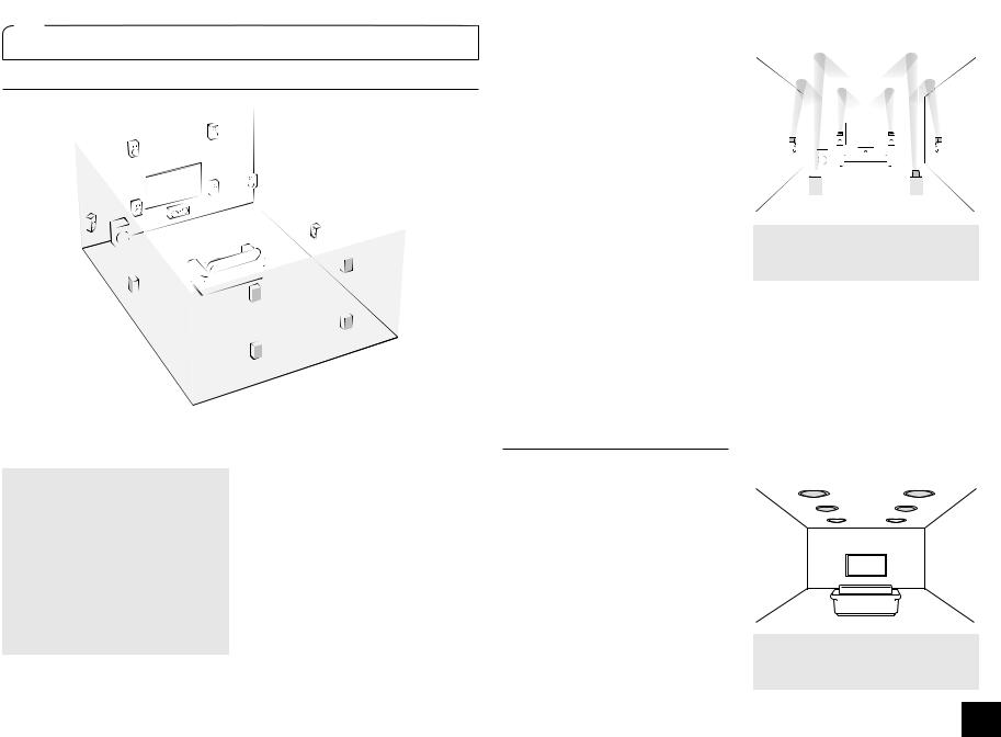
2 Connecting speakers
Speaker layout
F
|
9 |
|
|
|
" |
J |
|
# |
|
|
|
I ' |
$ |
& |
|
|
|
|
|
% |
|
|
H |
|
|
|
G |
|
|
|
8 |
|
|
|
7 |
|
|
|
|
To enjoy the Dolby Atmos listening mode, Height 1 speakers or surround back speakers need to be installed.
" # Front speakers $ Center speaker
% & Surround speakers
'Subwoofer
7 8 Surround back speakers
9 F Height 1 speakers (Front High) G H Height 2 speakers (Rear High) I J Wide speakers
r GH and IJ share the same speaker terminals. Select either of the groups.
r To use the multi-zone function, see the section 5 "Using the multi-zone function" of "Step 3: Playing Back".
5.1 ch: Connect the speakers
"#$%&' to the unit. "# output front stereo sound. $outputs center sounds such as dialogs and vocals. %& create back sound field. ' reproduces bass sounds and creates rich sound field. Up to four subwoofers can be connected to the unit.
Surround back speakers: Placing
78 URGCMGTU CNNQYU RNC[DCEM KP |EJ configuration that improves sense of envelopment created by back sound field. It also improves seamlessness of back sounds and provides more natural sound experiences in the sound field.
Height speakers 1 and 2: Placing 9F or
GH speakers produce surround effects on a height plane.
r To enjoy the Dolby Atmos listening mode, Height 1 speakers or surround back speakers need to be installed.
r Although Height 1 speakers can enhance surround effects, we recommend you to add Height 2 speakers in order to ensure full effects.
r Install Height speakers such as Front High and Rear High speakers on the upper part of the front or rear wall. There are other types of Height speakers.
Wide speakers: Placing IJ speakers makes the front sound field even wider. It also give smoother transitions between front and back surround sounds.
The power amplifier of this unit is designed for 9 ch configuration. Therefore, 78 speakers cannot be used together with GH (or IJ) speakers during playback. When both groups are connected, you can switch speakers to be used on the Quick Setup menu that appears when you press Q Setup on the remote controller (Speaker Layout function).
r For details on the Speaker Layout function, see the section 4 "Using Quick Setup menu" of "Step 3: Playing Back".
r 11 ch playback is possible by connecting an external power amplifier to this unit.
See the Advanced Manual for information on how to connect the external amplifier.
Height speakers arrangements (Dolby Atmos)
There are several types of Height speakers other than those mentioned in the previous section. See the next section "Combination patterns of Height speakers 1 and 2" and select the combination pattern from those specified for
Height speakers 1 and Height speakers 2. r This unit performs optimal sound field
processing for the type of Height speakers 1 and 2 which is registered in initial settings (with setup wizard) according to an actual speaker layout. Note that the optimal effect cannot be achieved if you place Height speakers in a combination pattern other than those specified.
r Dolby recommends to place the speakers as described on “Installing speakers in ceiling” to obtain the best Dolby Atmos effect.
Step 1: Connections
Using Dolby Enabled Speakers
c |
a |
|
|
|
b |
d |
||
|
|
|
|
|
|
|
||
|
|
|
|
|
|
|
|
|
|
|
|
|
|
|
|
|
|
 e
e f
f

a b Dolby Enabled Speaker (Front) c d Dolby Enabled Speaker (Surround) e f Dolby Enabled Speaker (Back)
A Dolby Enabled Speaker is specially designed to be used as a Height speaker. There are two types of Dolby Enabled Speakers, the one is to be placed on the top board of other speakers such as front speakers and surround speakers, and the other is integrated type with the normal speakers. Dolby Enabled Speakers designed with their output facing toward the ceiling to create an elevated audio effect in the Dolby
Atmos and Dolby Surround listening modes by providing sounds echoing off the ceiling.
Installing speakers in ceiling
k |
l |
i |
j |
 g h
g h
g h Top Front
i j Top Middle
k l Top Rear
5
Ceiling speakers, etc. are used for maximizing effects in Dolby Atmos or Dolby Surround listening mode. Install Top Front speakers midway between the position just above the listening position and the position just above the front speakers. Install Top Middle speakers just above the listening position. Install Top Rear speakers midway between the position just above the listening position and the position just above the surround back speakers.
Combination patterns for Height speakers 1 and 2
Dolby recommends the following combination pattern to obtain the best effect of Dolby Atmos and Dolby Surround listening modes.
r Pair 1: Top Middle
r Pair 2: Top Front / Top Rear
The following are the patterns of Height speakers 2 that can be selected according to the type of Height speakers 1.
Height speakers1: Front High
Height speakers 2: Not Use/Top Middle/Rear High/Dolby Enabled Speaker (Surround)/Dolby Enabled Speaker (Back)
Height speakers1: Top Front
Height speakers 2: Not Use/Top Rear
Height speakers1: Top Middle
Height speakers 2 cannot be used.
Height speakers1: Dolby Enabled Speaker (Front)
Height speakers 2: Not Use/Dolby Enabled Speaker (Surround)/Dolby Enabled Speaker (Back)
Height speakers1: Dolby Enabled Speaker (Surround)
Height speakers 2 cannot be used.
Height speakers1: Dolby Enabled Speaker (Back)
Height speakers 2 cannot be used.
r When front speakers are bi-amp connected, you can select a pattern for Height speakers 2 from the following options. Not Use/Front High/Top Front/Top Middle/Dolby Enabled Speaker (Front)/Dolby Enabled Speaker (Surround)/ Dolby Enabled Speaker (Back)
|
|
|
Step 1: Connections |
& |
8 |
7 |
% |
Surround R |
Surround back R |
Surround back L |
Surround L |
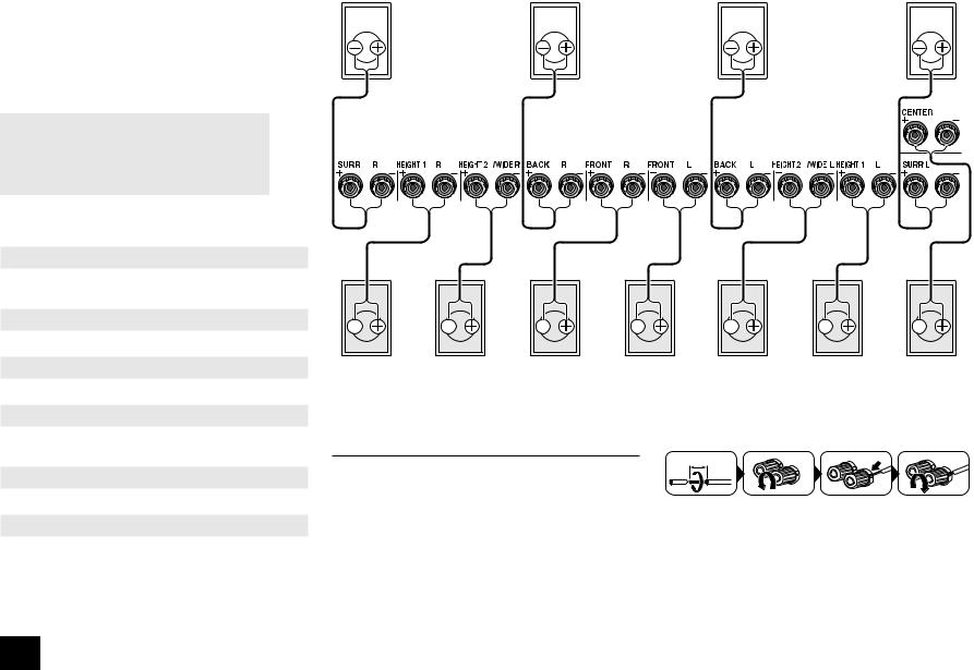
If you use only one surround back speaker, connect it to the BACK L terminal.
|
|
|
|
|
|
|
|
|
|
|
|
|
|
|
|
|
|
|
|
|
|
|
|
|
|
|
|
|
|
|
|
|
|
|
|
|
|
|
|
|
|
|
|
|
|
|
|
|
|
|
|
|
|
|
|
|
|
|
|
|
|
|
F |
|
|
H |
" |
# |
|
|
|
G |
9 |
|
$ |
||||||||||||||
Height1 R |
Height2 R/ |
Front R |
|
Front L |
Height2 L/ |
Height1 L |
Center |
||||||||||||||||||||||
|
|
|
|
|
|
|
J |
|
|
|
|
|
|
|
|
|
|
I |
|
|
|
|
|
|
|
|
|||
|
|
|
|
|
|
Wide R |
|
|
|
|
|
|
|
|
|
Wide L |
|
|
|
|
|
|
|
|
|||||
Instructions on how to connect speakers
Important %QPPGEV URGCMGTU YKVJ ŝ VQ ŝ KORGFCPEG
You have to change the setting if any of the speakers
JCXG ŝ QT OQTG VQ NGUU VJCP ŝ KORGFCPEG ;QW ECP UGV up by viewing the guidance displayed on the TV screen. Press Receiver and then Home on the remote controller. Select "Setup" - "2.Speaker Setup" - "Speaker Settings" - "Speaker Impedance" and change the default value from "6ohms" to "4ohms".
r Select the item with the cursor buttons of the remote controller and press Enter to confirm your selection. To return to the previous screen, press Return.
1/2"-5/8"(12-15 mm)
Cut and remove the plastic coating from the end of the speaker cable, twist the core and connect it to the terminal. Make correct connection between the unit's jacks and speaker's jacks (+ to + and - to -) for each channel. If connection is wrong, a bass sound may become poor
due to reverse phase. Attaching the supplied colored speaker cable labels to the + side on the both ends of each channel's cable will help correct connection.
6
Connecting the Subwoofer
Up to four subwoofers with built-in power amplifier can be connected to the subwoofer jacks. Set the cut-off filter selection switch of the subwoofer to DIRECT. If the subwoofer does not have a cut-off filter selection switch but has a cut-off frequency adjusting dial, turn it to the maximum frequency.
Subwoofer with built-in power amplifier
r The speaker setting is 7.2 ch at the time of purchase. You can change it manually or by using automatic speaker setting.
r Short-circuiting the + cable and - cable or contacting the cable core to the rear panel of the unit may cause failure.
Also do not connect two or more cables to one speaker terminal or one speaker to several terminals.
r Using a speaker with less impedance than the setting may result in failure.
When using commercially available banana plugs: tighten the speaker terminals to the end and then insert the banana plugs. Do not insert the cable core directly into the hole for banana plug of speaker terminal. (North American model)
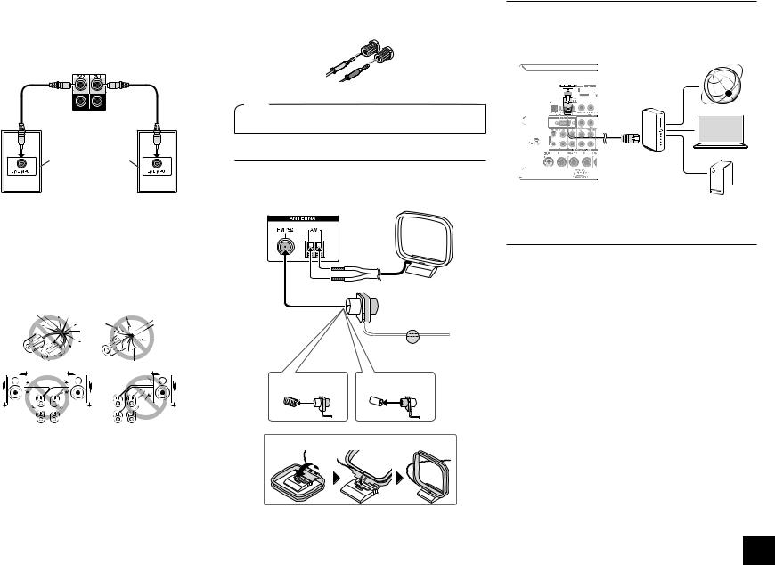
3 Other connections
AM/FM Antenna Connections
Connect the antennas to listen to AM/FM broadcast. When listening to the broadcast for the first time, adjust the antenna position and orientation to get the best reception.
AM loop antenna (supplied)
Indoor FM antenna (supplied)
Fix with a tack on the wall.
(North American models) |
(Australian models) |
Step 1: Connections
Network Connection
You can enjoy Internet radio and DLNA by connecting the unit to LAN. The unit can be connected to the router with an Ethernet cable. Connect the Ethernet cable to the Ethernet port.
Internet radio
PC
Router
NAS
Headphones Connection
%QPPGEV UVGTGQ JGCFRJQPGU YKVJ C UVCPFCTF RNWI |KPEJ QT Ô |OO VQ VJG 2*10'5 LCEM QP VJG HTQPV RCPGN
Sound from the speakers will be off while you are using the headphones.
r If you selected any other listening mode than Stereo, Mono and Direct, connecting headphones will switch the listening mode to Stereo.
Assemble the AM loop antenna (supplied).
7
Step 2: Setting Up
Important: When the unit is turned on for the first time, the setup wizard of the section 2 will automatically be launched. If you use the setup wizard to make the initial setup, connect a TV to the HDMI OUT MAIN or SUB jack of the unit via HDMI connection.
1 Turning the power on
Connect the power cord to the outlet. Press zOn/Standby on the main unit or zReceiver on the remote controller to turn the unit on or to standby mode.
2 |
Making the Initial Setup with the Setup Wizard |
|
Read before starting the procedure: Set up by answering the guidance displayed on the TV screen. Select the item with the cursor buttons of the remote controller and press Enter to confirm your selection. To return to the previous screen, press Return.
r If you terminate the procedure on the way or change the setting made in the initial setup and want to call up the setup wizard again, press Receiver and then Home on the remote controller, select "Setup" - "7.Hardware Setup" - "Initial Setup", and press Enter.
Initial Setup |
Language Select |
English |
Deutsch |
Français |
Español |
Italiano |
Nederlands |
Svenska |
HOME Exit |
¼This unit includes a removable power cord. Connect the power cord to AC INLET of the unit and then connect to the outlet. Always disconnect the outlet side first when disconnecting the power cord. When the unit is turned on, a large instantaneous current may flow affecting functionality of the computer and other devices. It is recommended to use a separate outlet from that for the computer or such other sensitive devices.
Firmware update notification: If the unit is connected via LAN and there is firmware update available, the "Firmware Update Available" message will appear. To execute updating, select "Update Now" with the cursor buttons of the remote controller and press Enter. When "Completed!" appears, press zOn/Standby on the main unit to turn the unit into standby mode. Then updating will be completed. r The unit automatically turns itself into standby mode 3
minutes after "Completed!" appears on the display. In this case also, updating will be completed.
Select the language first. In the next screen, the summary of the setup wizard as below will be displayed. Select "Yes" in this screen and press Enter on the remote controller.
Initial Setup
Welcome to initial setup. Have you connected all the speakers and devices?
Before starting, please connect speakers and sources.
Now, would you like to start initial setup? 1st Step : AccuEQ Room Calibration 2nd Step : Source Connection
3rd Step : Remote Mode Setup 4th Step : Network Connection
Yes
No
HOME Exit
The setup wizard proceeds in the four steps as below.
1st Step : AccuEQ Room Calibration
2nd Step : Source Connection
3rd Step : Remote Mode Setup
4th Step : Network Connection
1st Step : AccuEQ Room Calibration
The test tone coming from each speaker will be measured to enable setting of the number of speakers, volume level, each speaker's optimum crossover frequencies, and distance from the primary listening position, and also enable correction of distortion caused by the room acoustic environment.
r You cannot return to the previous screen during speaker setup, even if you press Return.
r You cannot setup the wide speaker setting in the setup wizard. For details on setting up the wide speakers, see the Advanced Manual.
Initial Setup
AccuEQ Room Calibration
This step you can automatically calibrate your room to get correct surround sound. Would you like to cailbrate your room now or later?
Do it Now
Do it Later
HOME Exit
1.Place the speaker setup microphone.
When the start screen above is displayed, before starting the procedure, place the supplied speaker setup microphone at the measurement position by referring to the figure below.
TV
Listening area |
Measurement position |
|
with microphone |
¼Correct measurement will not be possible if the microphone is held by hand. Measurement is not possible if headphones are being used.
¼The subwoofer sound may not be detected since it is extremely low frequencies. Raise the subwoofer volume to around the half of its maximum volume and make its frequency to the maximum level.
¼A loud test tone will be heard during measurement. Measurement may be interrupted if there is ambient noise or radio frequency interference. Close the window and turn off the home appliance and fluorescent light.
8
 Loading...