


DTR-6.5,5.5_En.book Page 1 Wednesday, July 28, 2004 9:07 AM
AV Receiver
DTR-6.5/5.5
Instruction Manual
DTR-6.5,5.5_En.book Page 2 Wednesday, July 28, 2004 9:07 AM
WARNING:
TO REDUCE THE RISK OF FIRE OR ELECTRIC SHOCK, DO NOT EXPOSE THIS APPARATUS TO RAIN OR MOISTURE.
CAUTION:
TO REDUCE THE RISK OF ELECTRIC SHOCK, DO NOT REMOVE COVER (OR BACK). NO USER-SERVICEABLE PARTS INSIDE. REFER SERVICING TO QUALIFIED SERVICE PERSONNEL.
WARNING |
|
AVIS |
RISK OF ELECTRIC SHOCK |
|
RISQUE DE CHOC ELECTRIQUE |
DO NOT OPEN |
|
NE PAS OUVRIR |
|
|
|
The lightning flash with arrowhead symbol, within an equilateral triangle, is intended to alert the user to the presence of uninsulated “dangerous voltage” within the product’s enclosure that may be of sufficient
magnitude to constitute a risk of electric shock to persons.
The exclamation point within an equilateral triangle is intended to alert the user to the presence of important operating and maintenance (servicing) instructions in the literature accompanying the appliance.
Important Safety Instructions
1.Read these instructions.
2.Keep these instructions.
3.Heed all warnings.
4.Follow all instructions.
5.Do not use this apparatus near water.
6.Clean only with dry cloth.
7.Do not block any ventilation openings. Install in accordance with the manufacturer’s instructions.
8.Do not install near any heat sources such as radiators, heat registers, stoves, or other apparatus (including amplifiers) that produce heat.
9.Do not defeat the safety purpose of the polarized or grounding-type plug. A polarized plug has two blades with one wider than the other. A grounding type plug has two blades and a third grounding prong. The wide blade or the third prong are provided for your safety. If the provided plug does not fit into your outlet, consult an electrician for replacement of the obsolete outlet.
10.Protect the power cord from being walked on or pinched particularly at plugs, convenience receptacles, and the point where they exit from the apparatus.
11.Only use attachments/accessories specified by the manufacturer.
12. Use only with the cart, stand, tripod, bracket, or table specified by the manufacturer, or sold with the apparatus. When a cart is used, use caution when moving the cart/ apparatus combination to avoid injury from tip-over.
13.Unplug this apparatus during lightning storms or when unused for long periods of time.
14.Refer all servicing to qualified service personnel. Servicing is required when the apparatus has been damaged in any way, such as power-supply cord or plug is damaged, liquid has been spilled or objects have fallen into the apparatus, the apparatus has been exposed to rain or moisture, does not operate normally, or has been dropped.
15.Damage Requiring Service
Unplug the apparatus from the wall outlet and refer servicing to qualified service personnel under the following conditions:
A.When the power-supply cord or plug is damaged,
B.If liquid has been spilled, or objects have fallen into the apparatus,
C.If the apparatus has been exposed to rain or water,
D.If the apparatus does not operate normally by following the operating instructions. Adjust only those controls that are covered by the operating instructions as an improper adjustment of other controls may result in damage and will often require extensive work by a qualified technician to restore the apparatus to its normal operation,
E.If the apparatus has been dropped or damaged in any way, and
F.When the apparatus exhibits a distinct change in performance this indicates a need for service.
16.Object and Liquid Entry
Never push objects of any kind into the apparatus through openings as they may touch dangerous voltage points or short-out parts that could result in a fire or electric shock.
The apparatus shall not be exposed to dripping or splashing and no objects filled with liquids, such as vases shall be placed on the apparatus.
Don’t put candles or other burning objects on top of this unit.
17.Batteries
Always consider the environmental issues and follow local regulations when disposing of batteries.
18.If you install the apparatus in a built-in installation, such as a bookcase or rack, ensure that there is adequate ventilation.
Leave 20 cm (8") of free space at the top and sides and 10 cm (4") at the rear. The rear edge of the shelf or board above the apparatus shall be set 10 cm (4") away from the rear panel or wall, creating a flue-like gap for warm air to escape.
2
DTR-6.5,5.5_En.book Page 3 Wednesday, July 28, 2004 9:07 AM
Precautions
For U.S. Models
Note to CATV system installer:
This reminder is provided to call the CATV system installer’s attention to Section 820-40 of the NEC which provides guidelines for proper grounding and, in particular, specifies that the cable ground shall be connected to the grounding system of the building, as close to the point of cable entry as practical.
FCC Information for User
CAUTION:
The user changes or modifications not expressly approved by the party responsible for compliance could void the user’s authority to operate the equipment.
NOTE:
This equipment has been tested and found to comply with the limits for a Class B digital device, pursuant to Part 15 of the FCC Rules.
These limits are designed to provide reasonable protection against harmful interference in a residential installation. This equipment generates, uses and can radiate radio frequency energy and, if not installed and used in accordance with the instructions, may cause harmful interference to radio communications. However, there is no guarantee that interference will not occur in a particular installation.
If this equipment does cause harmful interference to radio or television reception, which can be determined by turning the equipment off and on, the user is encouraged to try to correct the interference by one or more of the following measures:
•Reorient or relocate the receiving antenna.
•Increase the separation between the equipment and receiver.
•Connect the equipment into an outlet on a circuit different from that to which the receiver is connected.
•Consult the dealer or an experienced radio/TV technician for help.
1.Recording Copyright—Unless it’s for personal use only, recording copyrighted material is illegal without permission of the copyright holder.
2.AC Fuse— The AC fuse inside the AV receiver is not user-serviceable. If you cannot turn on the AV receiver, have it checked by the dealer from whom you purchased this unit.
3.Care—Occasionally you should dust the AV receiver all over with a soft cloth. For stubborn stains, use a soft cloth dampened with a weak solution of mild detergent and water. Dry the AV receiver immediately afterwards with a clean cloth. Don’t use abrasive cloths, thinners, alcohol, or other chemical solvents, because they may damage the finish or remove the panel lettering.
4.Power
WARNING
BEFORE PLUGGING IN THE UNIT FOR THE FIRST TIME, READ THE FOLLOWING SECTION CAREFULLY.
AC outlet voltages vary from country to country. Make sure that the voltage in your area meets the voltage requirements printed on the AV receiver’s rear panel (e.g., AC 230 V, 50 Hz or AC 120 V, 60 Hz).
Setting the [Standby/On] switch to Standby does not fully shutdown the AV receiver. If you do not intend to use the AV receiver for an extended period, remove the power cord from the wall outlet.
For Canadian model
NOTE: THIS CLASS B DIGITAL APPARATUS COMPLIES WITH CANADIAN ICES-003.
For models having a power cord with a polarized plug:
CAUTION: TO PREVENT ELECTRIC SHOCK, MATCH WIDE BLADE OF PLUG TO WIDE SLOT, FULLY INSERT.
Modèle pour les Canadien
REMARQUE: CET APPAREIL NUMÉRIQUE DE LA CLASSE B EST CONFORME À LA NORME NMB-003 DU CANADA.
Sur les modèles dont la fiche est polarisée:
ATTENTION: POUR ÉVITER LES CHOCS ÉLECTRIQUES, INTRODUIRE LA LAME LA PLUS LARGE DE LA FICHE DANS LA BORNE CORRESPONDANTE DE LA PRISE ET POUSSER JUSQU’AU FOND.
Thank you for purchasing an Integra AV Receiver.
Please read this manual thoroughly before making any connections and plugging it in. Following the instructions in this manual will enable you to obtain optimum performance and listening enjoyment from your new AV Receiver.
Please retain this manual for future reference.
3
DTR-6.5,5.5_En.book Page 4 Wednesday, July 28, 2004 9:07 AM
Precautions—Continued
For British models
Replacement and mounting of an AC plug on the power supply cord of this unit should be performed only by qualified service personnel.
IMPORTANT
The wires in the mains lead are coloured in accordance with the following code:
Blue: Neutral Brown: Live
As the colours of the wires in the mains lead of this apparatus may not correspond with the coloured markings identifying the terminals in your plug, proceed as follows:
The wire which is coloured blue must be connected to the terminal which is marked with the letter N or coloured black.
The wire which is coloured brown must be connected to the terminal which is marked with the letter L or coloured red.
IMPORTANT
A 5 or 13 ampere fuse is fitted in this plug. Should the fuse need to be replaced, please ensure that the replacement fuse has a rating of 5 or 13 amperes and that it is approved by ASTA or BSI to BS1362. Check for the ASTA mark or the BSI mark on the body of the fuse. IF THE FITTED MOULDED PLUG IS UNSUITABLE FOR THE SOCKET OUTLET IN YOUR HOME THEN THE FUSE SHOULD BE REMOVED AND THE PLUG CUT OFF AND DISPOSED OF SAFELY. THERE IS A DANGER OF SEVERE ELECTRICAL SHOCK IF THE CUT OFF PLUG IS INSERTED INTO ANY 13 AMPERE SOCKET.
If in any doubt, consult a qualified electrician.
For European Models
Declaration of Conformity
We, ONKYO EUROPE ELECTRONICS GmbH LIEGNITZERSTRASSE 6, 82194 GROEBENZELL, GERMANY
declare in own responsibility, that the ONKYO product described in this instruction manual is in compliance with the corresponding technical standards such as EN60065, EN55013, EN55020 and EN61000-3-2, -3-3.
GROEBENZELL, GERMANY
I. MORI
ONKYO EUROPE ELECTRONICS GmbH
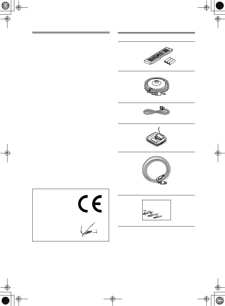
Supplied Accessories
Make sure you have the following accessories:
Remote controller & three batteries (AA/R6)
Speaker setup microphone
Indoor FM antenna
AM loop antenna
Power cord
(Plug type varies from country to country.)
Front |
Left |
Front |
Left |
SP-B /Zone2 |
Left |
SP-B /Zone2 |
Left |
Front |
Right |
Front |
Right |
SP-B /Zone2 |
Right |
SP-B /Zone2 |
Right |
Surround |
Left |
Surround |
Left |
Surround |
Right |
Surround |
Right |
Center |
Center |
SurroundBack |
Left |
SurroundBack |
Left |
Zone2 |
Left |
Zone2 |
Left |
SurroundBack |
Right |
SurroundBack |
Right |
Zone2 |
Right |
Zone2 |
Right |
Front |
Left |
Front |
Left |
SP-B / Zone 2 |
Left |
SP-B / Zone 2 |
Left |
Front |
Right |
Front |
Right |
SP-B / Zone 2 |
Right |
SP-B / Zone 2 |
Right |
Surround |
Left |
Surround |
Left |
Surround |
Right |
Surround |
Right |
Center |
Center |
Surround Back |
Left |
Surround Back |
Left |
Zone 2 |
Left |
Zone 2 |
Left |
Surround Back |
Right |
Surround Back |
Right |
Zone 2 |
Right |
Zone 2 |
Right |
1
2
3
Speaker Cable
Speaker cable labels
*In catalogs and on packaging, the letter at the end of the product name indicates the color. Specifications and operation are the same regardless of color.
4
DTR-6.5,5.5_En.book Page 5 Wednesday, July 28, 2004 9:07 AM
Features
DTR-6.5/5.5
Amplifier
•7-channel amplifier
•Optimum Gain Volume Circuitry
•Zone 2 capability
•24-bit/192 kHz D/A converters
•WRAT (Wide Range Amplifier Technology)
•Color-coded speaker terminal posts
Audio/Video
•Dolby*1 Digital, Dolby Digital EX, Dolby Pro Logic IIx
•DTS*2, DTS-ES Discrete, DTS-ES Matrix, DTS Neo:6, and DTS 96/24
•Theater-Dimensional*3 virtual surround mode
•VLSC (Vector Linear Shaping Circuitry) on all channels
•Zone 2 out
•Composite video to S-Video and S-Video to composite video conversion
•Composite and S-Video to component video conversion
•3 component video inputs, 1 output
•5 S-Video inputs, 3 outputs
FM/AM Tuner
•40 AM/FM presets
•AM/FM auto tuning
DTR-6.5
Amplifier
•100 watts per channel into 8 ohms, 20 Hz to 20 kHz, less than 0.08% total harmonic distortion (FTC rating)
Audio/Video
•THX*4 Surround EX
•THX Select certified
•Re-EQ
•Pre outs for front L/R, center, surround L/R, surround back L/R, and subwoofer
•7 digital inputs (5 optical, 2 coaxial), 2 digital outputs (1 optical, 1 coaxial)
THX Select
Before any home theater component can be THX Select certified, it must pass a rigorous series of quality and performance tests. Only then can a product feature the THX Select logo, which is your guarantee that the Home Theater products you purchase will give you superb performance for many years to come. THX Select requirements define hundreds of parameters, including power amplifier performance, and pre-ampli- fier performance and operation for both digital and analog domains. THX Select receivers also feature proprietary THX technologies (e.g., THX Mode) which accurately translate movie soundtracks for home theater playback.
Others
•Includes microphone for automatic speaker setup
•Easy-to-use onscreen setup menus
•Preprogrammed remote controller for use with other AV components
*1. Manufactured under license from Dolby Laboratories. “Dolby”, “Pro Logic”, “Surround EX”, and the double-D symbol are trademarks of Dolby Laboratories.
*2. “DTS”, “DTS 96/24”, “DTS-ES”, and “Neo:6” are trademarks of Digital Theater Systems, Inc.
*3. “Theater-Dimensional” is a trademark of Onkyo Corporation.
DTR-5.5
Amplifier
•85 watts per channel into 8 ohms, 20 Hz to 20 kHz, less than 0.08% total harmonic distortion (FTC rating)
Audio/Video
•CinemaFILTER*5
•Subwoofer pre out
•6 digital inputs (4 optical, 2 coaxial), 1 digital optical output.
*4. “THX” is a trademark or registered trademark of THX Ltd. “Surround EX” is a trademark of Dolby Laboratories. Used under authorization. All rights reserved.
*5. “CinemaFILTER” is a trademark of Onkyo Corporation. “Xantech” is a registered trademark of Xantech Corporation. “Niles” is a registered trademark of Niles Audio Corporation.
5
DTR-6.5,5.5_En.book Page 6 Wednesday, July 28, 2004 9:07 AM
Table of Contents |
|
|
|
Basic |
|
Introduction |
|
|
Important Safety Instructions .......................................................................................... |
2 |
|
Precautions ....................................................................................................................... |
|
3 |
Supplied Accessories....................................................................................................... |
4 |
|
Features ............................................................................................................................. |
|
5 |
Table of Contents .............................................................................................................. |
6 |
|
Front & Rear Panels.......................................................................................................... |
8 |
|
Remote Controller........................................................................................................... |
13 |
|
About Home Theater ....................................................................................................... |
20 |
|
Connecting the AV receiver |
|
|
About AV Connections ................................................................................................... |
21 |
|
Connecting Your Speakers............................................................................................. |
22 |
|
Connecting Antenna....................................................................................................... |
24 |
|
Connecting Both Audio & Video.................................................................................... |
26 |
|
Which Connections Should I Use? ............................................................................... |
26 |
|
Connecting Your TV or Projector ................................................................................... |
27 |
|
Connecting AV components .......................................................................................... |
28 |
|
Connecting Audio components..................................................................................... |
34 |
|
Connecting a Power Amplifier (DTR-6.5 only).............................................................. |
37 |
|
Connecting |
Components ........................................................................................ |
37 |
Connecting the Power Cords of Other Components................................................... |
38 |
|
Connecting the Supplied Power Cord........................................................................... |
38 |
|
Turning On the AV receiver ............................................................................................ |
38 |
|
First Time Setup |
|
|
Automatic Speaker Setup............................................................................................... |
39 |
|
About the Onscreen Setup Menus ................................................................................ |
41 |
|
Initial Setup...................................................................................................................... |
|
42 |
Digital Input ................................................................................................................... |
|
42 |
Component Video Setup ............................................................................................... |
43 |
|
Minimum Speaker Impedance (not American models) ................................................. |
44 |
|
TV Format Setup (not American models)...................................................................... |
45 |
|
Speaker Setup ................................................................................................................. |
|
46 |
Changing the TAPE/MD/CDR Display ............................................................................ |
52 |
|
Basic Operation |
|
|
Selecting the Input Source............................................................................................. |
53 |
|
Setting the Display Brightness...................................................................................... |
54 |
|
Muting the AV receiver ................................................................................................... |
54 |
|
Using the Sleep Timer..................................................................................................... |
54 |
|
Using Headphones ......................................................................................................... |
54 |
|
Displaying Source Information ...................................................................................... |
55 |
|
Using the Tuner ............................................................................................................... |
|
56 |
Selecting Listening Modes............................................................................................. |
58 |
|
Listening mode table ..................................................................................................... |
59 |
|
About the Listening Modes............................................................................................ |
60 |
|
Others |
|
|
Troubleshooting |
.............................................................................................................. |
90 |
Specifications.................................................................................................................. |
|
94 |
6
DTR-6.5,5.5_En.book Page 7 Wednesday, July 28, 2004 9:07 AM
Table of Contents—Continued
Advanced
Advanced
Features
Advanced
Features
Advanced
Features
Advanced
Features
Controlling Other Components |
|
Entering a Remote Control Codes................................. |
80 |
Learning Commands from Another Remote |
|
Controller ..................................................................... |
88 |
Using Macros................................................................... |
89 |
Advanced Setup |
|
Decoder Setup................................................................. |
66 |
Adjusting the Bass & Treble........................................... |
68 |
Audio Adjust Functions.................................................. |
68 |
Assigning Listening Modes to Input Sources .............. |
70 |
Setting Preferences ........................................................ |
71 |
Changing the Remote Controller’s ID ........................... |
73 |
Advanced Operation |
|
Using the Late Night Function (Dolby Digital only) ..... |
62 |
Using the Re-EQ Function (DTR-6.5 only) .................... |
62 |
Using the CinemaFILTER (TDR-5.5 only) ...................... |
62 |
Adjusting Individual Speaker Levels............................. |
63 |
Using the DVD Analog Multichannel Input ................... |
63 |
Recording ........................................................................ |
64 |
Zone 2 |
|
Connecting Zone 2.......................................................... |
74 |
Setting the Powered Zone 2 ........................................... |
75 |
Setting the zone 2 OUT................................................... |
76 |
Using Zone 2.................................................................... |
77 |
Using the Remote Control in Zone 2 ............................. |
79 |
Introduction ............................... |
2 |
Connections ............................ |
21 |
First Setup ............................... |
39 |
Basic Operation ...................... |
53 |
Advanced Operation ............... |
62 |
Advanced Setup ...................... |
66 |
Zone 2 ...................................... |
74 |
Using the Remote Controller |
|
with Other Components ...... |
80 |
Troubleshooting ...................... |
90 |
Others....................................... |
94 |
7

DTR-6.5,5.5_En.book Page 8 Wednesday, July 28, 2004 9:07 AM
Front & Rear Panels
Front Panel
DTR-6.5
1 23456789J K L MN O PQ R S T
Zone 2
|
Standby |
|
U V W X |
Y |
Z |
DTR-5.5
1 23456789J K L MN O P Q R S T
Zone 2
|
Standby |
|
U V W X |
Y |
Z |
8
DTR-6.5,5.5_En.book Page 9 Wednesday, July 28, 2004 9:07 AM
Front & Rear Panels—Continued
For detailed information, see the pages in parentheses.
AStandby/On button (38)
This button is used to set the AV receiver to On or Standby. For models with a POWER switch, this button has no effect unless the POWER switch is set to ON.
BStandby indicator (38)
This indicator lights up when the AV receiver is in Standby mode, and it flashes while a signal is being received from the remote controller.
CZone 2 indicator (77)
This indicator lights up when Zone 2 is selected.
DRemote-control sensor (13)
This sensor receives control signals from the remote controller.
ERec Out button (64)
This button is used to select the input source to be recorded.
FZone 2 button (77)
This button is used to select the input source for Zone 2.
GLevel button (77)
This button is used to set the volume for Zone 2.
HTone button (78)
This button is used to adjust the bass and treble for Zone 2.
IController [ ] [
] [ ] buttons (64, 77, 78)
These buttons are used to select the input source to be recorded via the REC OUTs, to select the input source for Zone 2, and to set the volume, bass, and treble for Zone 2.
JStereo button (58)
This button is used to select the Stereo listening mode.
KListening Mode [ ] [
] [ ] buttons (58)
These buttons are used to select the listening modes.
LDisplay button (55)
This button is used to display various information about the currently selected input source.
MDisplay
See “Display” on page 10.
NMemory button (57)
RArrow/Tuning/Preset & Enter buttons (42)
When the AM or FM input source is selected, the
Tuning [ ] [
] [ ] buttons are used to tune the tuner, and the Preset [
 ] [
] [ ] buttons are used to select radio presets (see page 57). When the onscreen setup menus are used, they work as arrow buttons and are used to select and set items. The Enter button is also used with the onscreen setup menus.
SReturn button
This button is used to return to the previously displayed onscreen setup menu.
TMaster Volume control (53)
This control is used to adjust the volume of the AV receiver to MIN, 1 through 99, or MAX
UPure Audio indicator (58)
This indicator lights up when the Pure Audio listening mode is selected.
VPhones jack (54)
This 1/4-inch phone jack is for connecting a standard pair of stereo headphones for private listening.
WSetup Mic (39)
The included speaker setup microphone is connected here for automatic speaker setup.
XTone, [–] & [+] buttons (78)
These buttons are used to adjust the bass and treble.
YInput selector buttons (53)
These buttons are used to select from the following input sources: Multi CH, DVD, VIDEO 1,
VIDEO 2, VIDEO 3, VIDEO 4, TAPE, TUNER, CD, or PHONO (DTR-6.5 only).
The [Multi CH] button selects the DVD analog multichannel input.
ZVideo 4 Input (33, 65)
This input can be used to connect a camcorder, games console, and so on. There are jacks for optical digital audio, S-Video, composite video, and analog audio.
This button is used when storing or deleting radio presets.
OTuning Mode button (56)
This button is used to select the Auto or Manual tuning mode.
PDimmer button (54)
This button is used to adjust the display brightness.
QSetup button (42)
This button is used to access the onscreen setup menus that appear on the connected TV.
9

DTR-6.5,5.5_En.book Page 10 Wednesday, July 28, 2004 9:07 AM
Front & Rear Panels—Continued
Display
1 2 3 |
4 |
|
5 |
|||||
|
|
|
|
|
|
|
|
|
|
|
|
|
|
|
|
|
|
|
|
|
|
|
|
|
|
|
|
|
|
|
|
|
|
|
|
6 |
7 |
For detailed information, see the pages in parentheses.
1MUTING indicator (54)
This indicator flashes while the AV receiver is muted.
2REC OUT indicator (64)
This indicator lights up when the REC OUT is selected.
3ZONE 2 indicator (77)
This indicator lights up when Zone 2 is selected.
4Listening mode & format indicators
These indicators show the currently selected listening mode and the format of digital input signals.
5Tuning indicators (56)
TUNED: This indicator lights up when the AV receiver is tuned into a radio station.
AUTO: This indicator lights up when the Auto Tuning mode is selected, and disappears when the Manual Tuning mode is selected.
MEMORY: This indicator lights up when presetting radio stations.
FM STEREO: This indicator lights up when the AV receiver is tuned to a stereo FM station.
6SLEEP indicator (54)
This indicator lights up when the Sleep function has been set.
7Message area
This area of the display shows various information about the currently selected source.
Rear Panel
DTR-6.5
1 BCDE 6 G H9 J K |
L |
ZONE 2 SPEAKERS
|
|
|
|
|
|
|
|
|
|
|
|
|
|
|
L |
|
|
|
|
|
|
|
IN4 |
IN3 |
IN2 |
IN1 |
OUT |
|
DIGITAL |
|
|
|
|
|
|
|
|
|
|
COAXIAL |
|
|
|||||
|
|
|
|
|
|
|
|
|
|
|
|
|
|
|
|
|
COMPONENT VIDEO |
|
|
RS232 |
OPTICAL |
|
|
|
|
|
IN 2 |
IN 1 |
OUT |
R |
|
|
|
|
|
|
|
|
|
|
|
|
|
|
|||
IN 3 |
IN 2 |
IN 1 |
OUT |
|
|
|
|
|
|
|
|
|
|
|
|
Y |
|
|
|
VIDEO 3 |
VIDEO 2 |
|
VIDEO 1 |
DVD |
MONITOR |
|
PRE OUT |
|
|
||
|
|
|
|
|
|
|
|
||||||||
|
|
|
|
IN |
OUT |
IN |
OUT |
IN |
IN |
OUT |
FRONT |
SURR |
CENTER |
SURR BACK |
|
|
|
|
|
|
|
|
|
|
|
V |
|
L |
|
|
|
PB |
|
|
|
|
|
|
|
|
|
|
|
|
|
|
L |
|
|
|
|
|
|
|
|
|
|
S |
|
|
|
|
|
PR |
|
|
|
|
|
|
|
|
|
|
|
|
|
|
R |
|
|
|
|
|
|
|
|
|
|
|
|
R |
SUB |
|
|
|
|
|
|
|
|
|
|
|
|
|
|
|
|
|
|
|
|
|
|
|
|
|
|
|
|
|
|
|
WOOFER |
|
|
IN |
IN |
OUT |
IN |
IN |
OUT |
IN |
OUT |
IN |
FRONT |
SURR |
CENTER |
L |
ZONE 2 |
|
|
|
|
|
|
|
|
|
|
|
|
|
|
|
OUT |
|
|
L |
|
|
|
|
|
|
|
|
|
|
|
|
|
|
|
GND |
|
|
|
|
|
|
|
|
|
|
|
|
|
|
|
|
|
|
|
|
|
|
|
|
|
|
|
|
|
REMOTE |
|
R |
|
|
|
|
|
|
|
|
|
|
|
|
|
CONTROL |
|
|
|
|
|
|
|
|
|
|
|
|
|
|
|
|
|
|
|
|
|
|
|
|
|
|
|
|
SUB |
R |
SUB |
|
|
PHONO |
CD |
TAPE |
|
VIDEO 3 |
VIDEO 2 |
|
VIDEO 1 |
|
DVD |
WOOFER |
|
WOOFER |
|
|
|
OPQ R S T |
|
U |
|
V |
|
W |
X Y |
||||||||
|
M |
N |
SURROUND BACK |
SURROUND SPEAKERS |
|
SPEAKERS |
|
|
|
L |
|
|
R |
|
L |
|
|
|
CENTER SPEAKER |
|
R |
|
|
FRONT SPEAKERS |
|
|
Z |
10
DTR-6.5,5.5_En.book Page 11 Wednesday, July 28, 2004 9:07 AM
Front & Rear Panels—Continued
DTR-5.5
1 BCDE 6 G H9 J K |
|
L |
|
M |
N |
|||||||||||||
|
|
|
|
|
|
|
|
|
|
|
|
|
|
|
ZONE 2 SPEAKERS |
SURROUND BACK |
SURROUND SPEAKERS |
|
|
|
|
|
|
|
|
|
|
|
|
|
|
|
|
|
SPEAKERS |
|
|
|
|
|
|
|
|
|
|
|
|
|
|
|
|
|
|
|
L |
|
|
|
|
|
|
|
|
|
|
|
|
|
|
|
|
L |
|
|
|
|
|
|
|
|
|
|
IN3 |
IN2 |
IN1 |
OUT |
DIGITAL |
|
|
|
|
|
||
|
|
|
|
|
|
|
|
COAXIAL |
|
|
|
|
|
|||||
|
|
|
|
|
|
|
|
|
|
|
|
|
|
|
|
|
|
|
|
COMPONENT VIDEO |
|
|
RS232 |
|
OPTICAL |
|
|
|
|
IN 2 |
IN 1 |
R |
|
|
|
||
|
|
|
|
|
|
|
|
|
|
|
|
|
|
|
|
|||
IN 3 |
IN 2 |
IN 1 |
OUT |
|
|
|
|
|
|
|
|
|
|
|
|
|
|
|
|
|
|
|
|
|
|
|
|
|
|
|
|
|
|
|
|
R |
|
Y |
|
|
|
VIDEO 3 |
VIDEO 2 |
|
VIDEO 1 |
|
DVD |
MONITOR |
|
|
PRE OUT |
|
|
|
|
|
|
|
|
|
|
|
|
|
|
|
|
|
|||||||
|
|
|
|
IN |
OUT |
IN |
OUT |
IN |
IN |
OUT |
|
|
|
|
|
|
|
|
|
|
|
|
|
|
|
|
|
|
V |
|
|
|
|
|
|
|
|
PB |
|
|
|
|
|
|
|
|
|
|
|
|
SUB |
|
L |
|
|
|
|
|
|
|
|
|
|
|
|
|
|
|
WOOFER |
|
|
|
|||
|
|
|
|
|
|
|
|
|
|
S |
|
|
|
|
|
|
|
|
PR |
|
|
|
|
|
|
|
|
|
|
|
|
|
|
|
|
|
|
|
|
|
|
|
|
|
|
|
|
|
|
|
|
|
|
|
CENTER SPEAKER |
|
|
|
|
|
|
|
|
|
|
|
|
|
|
|
|
|
R |
|
|
|
IN |
OUT |
IN |
IN |
OUT |
IN |
OUT |
IN |
FRONT |
SURR |
CENTER |
L |
ZONE 2 |
|
|
|
|
|
|
|
|
|
|
|
|
|
|
|
|
|
|
OUT |
|
|
|
|
|
|
L |
|
|
|
|
|
|
|
|
|
|
|
|
|
|
FRONT SPEAKERS |
|
|
|
|
|
|
|
|
|
|
|
|
|
|
|
|
|
REMOTE |
|
|
|
|
R |
|
|
|
|
|
|
|
|
|
|
|
|
|
CONTROL |
|
|
|
|
|
|
|
|
|
|
|
|
|
|
|
|
|
|
|
|
|
|
|
|
|
|
|
|
|
|
|
|
|
SUB |
R |
|
|
|
|
|
|
|
CD |
TAPE |
|
VIDEO 3 |
VIDEO 2 |
|
VIDEO 1 |
|
|
DVD |
WOOFER |
|
|
|
|
|
|
|
|
|
|
|
|
|
|
|
|
|
|
|
|
||||||
|
Q R S T |
|
U |
|
|
V |
|
W |
|
XY |
|
|
Z |
|||||
For detailed information, see the pages in parentheses.
ACOMPONENT VIDEO IN 1, 2, 3 (28, 30, 32)
These component video inputs can be used to connect AV components with component video outputs, such as DVD players.
BAM ANTENNA (24)
These push terminals are for connecting an AM antenna.
CCOMPONENT VIDEO OUT (27)
This component video output can be used to connect a TV or projector with a component video input.
DFM ANTENNA (24)
This jack is for connecting an FM antenna.
ERS232 (38)
This port is for connecting the AV receiver to home automation equipment and external controllers.
F12V TRIGGER OUT A/B/C (73, 78)
These jacks can be connected to the 12-volt trigger inputs on other components. These trigger outputs can each be assigned to an input so that when that input is selected, a 12-volt trigger signal is output.
GIR IN/OUT (78)
These jacks are for connecting the remote sensors included with multiroom kits (sold separately).
HA-BUS
A-BUS is a simple, efficient, elegant audio distribution system. The wiring installation time is significantly reduced as only a single CAT-5 wire is run to each location. A-BUS is easy to use, reliable, affordable, and most of all, far better sounding than conventional auto former based volume controls.
ZONE 2 OUT: Use CAT-5 (eight conductor twisted) cable to connect directly from the receiver’s A-BUS RI45 Hub to an A-BUS keypad.
Warning:
DO NOT connect A-BUS output to any computer or network connections (i.e. ethernet). it will cause damage to the computer or network components as 24-volt power runs on this same cable to power the amplifier stages of the amplifier module.
IR OUT: Another feature of the A-BUS system is the ability to control source equipment in another room where the A-BUS module is installed. If you wish to control another source from the receiver at the A-BUS keypad by remote control, connect A-BUS or another brands’s IR emitter on the receiver’s 40 K terminal. Then place the emitter on the remote receiver on the front panel.
Typically, the emitter will work when you connect with a 40 K connector. If it does not work, try a 56 K connector.
DC IN: Connect A-Bus power supply. Do not use any other AC Adapter on this connector as it may cause severe damage to the receiver.
IMONITOR OUT (27)
The S-Video or composite video jack should be connected to a video input on your TV or projector.
11
DTR-6.5,5.5_En.book Page 12 Wednesday, July 28, 2004 9:07 AM
Front & Rear Panels—Continued
JOPTICAL DIGITAL (27, 28, 30, 32, 34, 35)
The DTR-5.5 doesn’t have an IN 4 jack.
The optical digital audio inputs can be used to connect CD and DVD players, and other components with an optical digital audio output.
The optical output can be used to connect a CD recorder or other digital recorder with an optical digital input.
KCOAXIAL DIGITAL (27, 28, 30, 32, 34, 35)
The coaxial digital audio inputs can be used to connect CD and DVD players, and other components with a coaxial digital audio output.
The coaxial output can be used to connect a CD recorder or other digital recorder with a coaxial digital input.
The DTR-5.5 do not have a coaxial output.
LZONE 2 SPEAKERS (74)
These terminal posts are for connecting speakers in Zone 2.
MFRONT, CENTER, SURROUND & SURROUND BACK SPEAKERS (23)
These terminal posts are for connecting your front, center, surround, and surround back speakers.
NAC OUTLETS (38)
These switched AC outlets can be used to supply power to other AV components. The type of outlet depends on the country in which you purchased your AV receiver. Some models have a single outlet.
OGrounding screw (DTR-6.5 only) (36)
This screw is for connecting a turntable’s ground wire.
PPHONO IN (DTR-6.5 only) (36)
This analog input is for connecting a turntable.
QCD IN (34)
VDVD IN (28, 29)
Here you can connect a DVD player. Input jacks include S-Video, composite video, and analog audio. You can connect a DVD player’s 2-channel analog audio output or 5.1-channel analog audio output.
WZONE 2 OUT (74)
This analog audio output can be connected to a line input on an integrated amplifier in Zone 2.
The DTR-6.5 also has a ZONE 2 OUT SUBWOOFER jack that can be used to feed a subwoofer in Zone 2.
These jacks can can be configured as either line outs or pre outs on the onscreen setup menus.
X
 REMOTE CONTROL (37)
This 
 (Remote Interactive) jack can be connected to an
 jack on another Integra AV component. The AV receiver’s remote controller can then
be used to control that component. To use 
 , you must make an analog audio connection (RCA) between the AV receiver and the other AV component, even if they are connected digitally.
YPRE OUT (37)
These analog audio outputs are for connecting a separate power amplifier. Useful if you want to connect a more powerful amplifier and use the AV receiver as a preamp. The SUBWOOFER jack is for connecting a powered subwoofer.
ZAC INLET (38)
The supplied power cord should be connected here.
This analog audio input is for connecting a CD player’s analog audio output.
RTAPE IN/OUT (34)
This analog audio input and output are for connecting a recorder with an analog audio input and output (cassette, Mini Disc, etc).
SVIDEO 3 IN (27, 31)
Here you can connect a video source (VCR, set-top box, etc). Input jacks include S-Video, composite video, and analog audio.
TVIDEO 2 IN/OUT (30, 31)
Here you can connect a VCR. Input and output jacks include S-Video, composite video, and analog audio.
UVIDEO 1 IN/OUT (30, 31)
Here you can connect a VCR. Input and output jacks include S-Video, composite video, and analog audio.
12
DTR-6.5,5.5_En.book Page 13 Wednesday, July 28, 2004 9:07 AM
Remote Controller
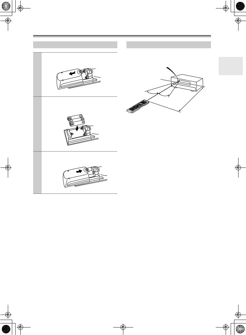
Installing the Batteries
1 To open the battery compartment, press the small hollow and slide off the cover.
2 Insert the three supplied batteries (AA/R6) in accordance with the polarity diagram inside the battery compartment.
3 Put the cover onto the remote controller and slide it shut.
Notes:
•The batteries should last for about six months, although this will vary with usage.
•If the remote controller doesn’t work reliably, try replacing the batteries.
•Don’t mix new and old batteries or different types of batteries.
•If you intend not to use the remote controller for a long time, remove the batteries to prevent damage from leakage or corrosion.
•Expired batteries should be removed as soon as possible to prevent damage from leakage or corrosion.
Using the Remote Controller
To use the remote controller, point it at the AV receiver’s remote control sensor, as shown below.
Remote control sensor
AV receiver
Standby indicator
|
|
|
. |
30˚ |
|
16 |
ft |
30˚ |
. |
|
|
|
x |
|
|
|
Approm) |
|
|
|
(5 |
|
|
Notes:
•The remote controller may not work reliably if the AV receiver is subjected to bright light, such as direct sunlight or inverter-type fluorescent lights. Keep this in mind when installing.
•If another remote controller of the same type is used in the same room, or the AV receiver is installed close to equipment that uses infrared rays, the remote controller may not work reliably.
•Don’t put anything, such as a book, on the remote controller, because the buttons may be pressed inadvertently, thereby draining the batteries.
•The remote controller may not work reliably if the AV receiver is installed in a rack behind colored glass doors. Keep this in mind when installing.
•The remote controller will not work if there’s an obstacle between it and the AV receiver’s remote control sensor.
13
DTR-6.5,5.5_En.book Page 14 Wednesday, July 28, 2004 9:07 AM
Remote Controller—Continued
In addition to controlling the AV receiver, the remote controller has several operating modes for controlling your other AV components, including Integra components connected via 
 . Modes are selected by using the remote controller’s Remote Mode buttons.
For detailed information, see the pages in parentheses. Some of the functions described in this manual may not work as expected with other components.
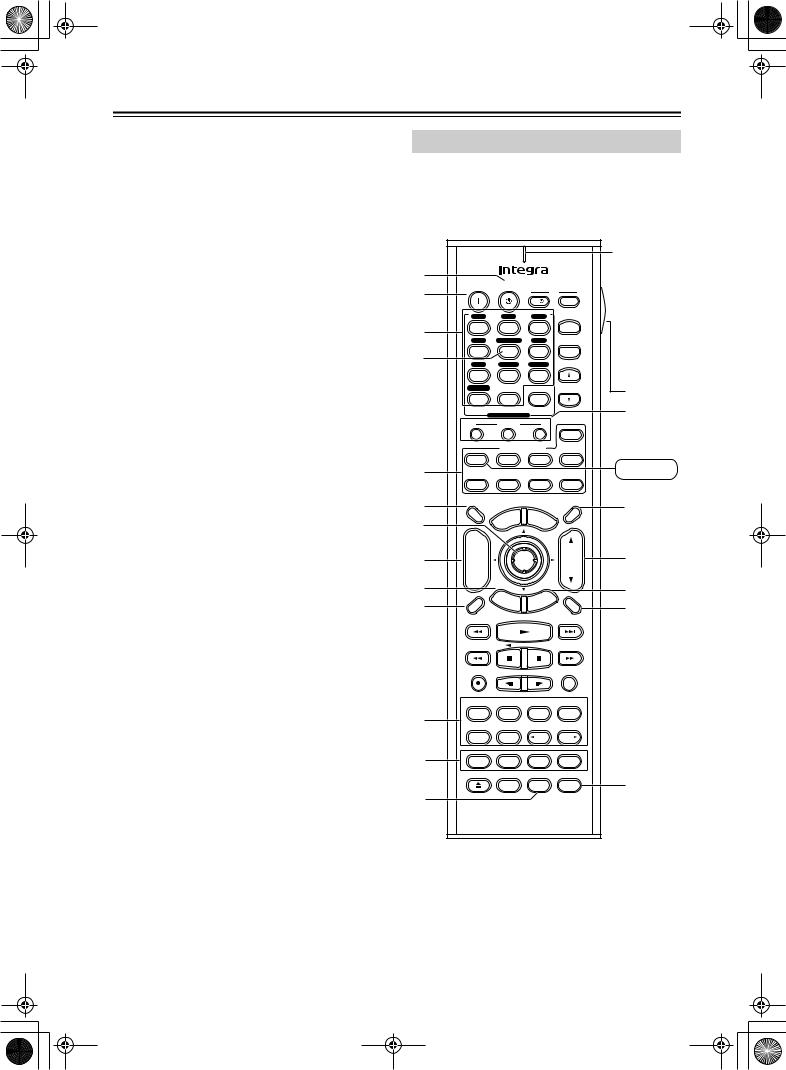
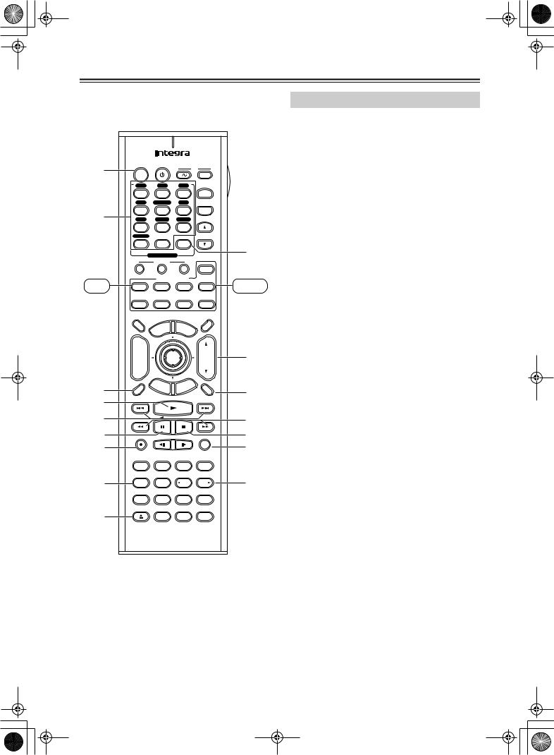
Receiver Mode
Receiver mode is used to control the AV receiver. To select Receiver mode, press the [Receiver] Remote Mode button.
RC-585M |
|
|
|
|
|
|
|
|
|
||
|
|
|
|
|
|
|
|
|
|
Remote |
|
|
|
|
|
|
|
|
|
|
|
indicator |
|
A |
|
|
|
|
|
|
|
|
TV |
This indicator |
|
B |
On |
Standby |
|
|
|
lights up |
|||||
|
|
|
|
|
|||||||
|
|
|
|
|
I |
|
Input |
when the |
|||
|
|
|
|
|
|
|
|||||
|
V1 |
|
V2 |
|
|
V3 |
|
+ |
remote con- |
||
3 |
1 |
|
2 |
|
|
3 |
|
troller is |
|||
V4 |
Multi CH |
DVD |
TV CH |
transmitting |
|||||||
|
|||||||||||
|
4 |
|
5 |
|
|
6 |
|
- |
|||
4 |
|
|
|
|
commands. |
||||||
CD |
|
Tape |
Tuner |
|
|||||||
|
|
|
|
||||||||
|
7 |
|
8 |
|
|
9 |
|
|
T |
||
|
Phono |
|
|
|
|
|
|
|
TV VOL |
||
|
+10 |
|
0 |
|
Clear |
|
|
||||
|
--/--- |
Input Selector |
|
|
|
|
N |
||||
|
|
|
|
|
|
||||||
|
|
Macro |
|
|
|
|
|
||||
|
1 |
|
2 |
|
|
3 |
|
Zone 2 |
|
||
|
|
|
Remote Mode |
|
|
|
|||||
|
Receiver |
|
DVD |
|
|
CD |
MD/CDR |
Receiver |
|||
5 |
Tape |
|
|
|
|
|
|
|
|
||
|
|
|
|
|
|
|
|
|
|
||
|
TV |
|
VCR |
Cable |
SAT |
|
|||||
6 |
Dimmer |
|
|
|
|
|
|
|
Sleep |
O |
|
|
|
|
|
|
u |
M |
|
|
|
||
|
TV |
|
en |
|
|
|
|||||
7 |
|
pM |
|
|
en |
|
|
||||
Input |
o |
|
|
|
|
u |
|
|
|||
|
T |
|
|
|
|
|
|
|
|
||
|
+ |
|
|
|
|
|
|
|
|
|
|
8 |
CH |
|
|
|
Enter |
|
|
VOL |
P |
||
Disc |
|
|
|
|
|
||||||
9 |
- |
|
E |
|
t |
G |
e |
|
Q |
||
|
|
xi |
|
||||||||
|
|
|
|
|
id |
|
|
|
|||
|
|
|
|
|
u |
|
|
|
|||
|
Prev |
R |
et |
|
|
|
|
p |
|
|
|
|
CH |
|
|
|
|
tu |
|
|
|||
J |
|
urn |
Se |
|
|
R |
|||||
Display |
|
|
|
|
|
|
|
Muting |
|||
|
|
|
|
|
|
|
|
|
|||
|
Rec |
|
|
|
|
|
|
|
Random |
|
|
|
Audio |
Subtitle |
Angle |
Last Memory |
|
||||||
K |
Surround |
|
All ST |
THX |
Stereo |
|
|||||
Repeat |
|
A-B |
|
Search |
Memory |
|
|||||
|
|
|
|
||||||||
|
Pure A |
|
Direct |
|
DSP |
DSP |
|
||||
L |
Test Tone |
CH SEL |
Level- |
Level+ |
|
||||||
|
Open/Close Video Off |
|
|
|
|
|
|||||
|
|
|
|
|
|
L Night |
Re-EQ |
S |
|||
M |
|
|
|
|
|
|
|
|
|
|
|
|
|
|
RC-585M |
|
|
|
|||||
14
DTR-6.5,5.5_En.book Page 15 Wednesday, July 28, 2004 9:07 AM
Remote Controller—Continued
RC-586M
Repeat |
A-B |
Search |
Memory |
Pure A |
Direct |
DSP |
DSP |
Test Tone |
CH SEL |
Level- |
Level+ |
Open/Close Video Off
L Night |
Cine Fltr |
U |
RC-586M
AStandby button (38)
This button is used to set the AV receiver to Standby.
BOn button (38)
This button is used to turn on the AV receiver.
CInput Selector buttons (53)
These buttons are used to select the input source. Only the RC-588M has a [PHONO] button.
DMulti CH button (63)
This button is used to select the DVD analog multichannel input.
ERemote Mode buttons
These buttons are used to select the remote controller modes.
FDimmer button (54)
This button is used to adjust the display brightness.
GArrow [ ]/[
]/[ ]/[
]/[ ]/[
]/[ ] & Enter buttons (42)
These buttons are used to select items on the onscreen setup menus.
HCH +/– button (57)
This button is used to select radio presets.
IReturn button
This button is used to return to the previously displayed onscreen setup menu.
JDisplay button (55, 57)
This button is used to display various information about the currently selected input source.
KListening mode buttons (58) Surrond button
This button is used to select the Dolby Digital, Pro Logic IIx, Neo:6, DTS and other listening modes.
All ST button
This button is used to select the All Ch Stereo listening mode.
THX button (RC-585M only)
This button is used to select the THX listening modes.
Stereo button
This button is used to select the Stereo listening mode.
Pure A button
This button is used to select the Pure Audio listening mode.
Direct button
This button is used to select the Direct listening mode.
[ DSP] & [DSP
  ] buttons
These buttons are used to select the Onkyo original DSP (digital signal processor) listening modes.
LTest Tone, CH SEL, Level- & Level+ buttons (50)
These buttons are used to adjust the level of each speaker individually. The [Level–] & [Level+] buttons are also used to adjust the volume in Zone 2.
ML Night button (62)
This button is used to set the Late Night function.
NMacro buttons (89)
These buttons are used with the Macro function.
OSleep button (54)
This button is used to set the Sleep function.
PVOL button (53)
This button is used to adjust the volume of the AV receiver.
QSetup button (42)
This button is used to access the onscreen setup menus that appear on the connected TV.
RMuting button (54)
This button is used to mute the AV receiver.
SRe-EQ button (RC-585M only) (62)
This button is used to turn the Re-EQ function on and off.
TLight button
This button is used to turn on or off the remote controller’s illuminated buttons.
UCine Fltr button (RC-586M only) (62)
This button is used to set the CinemaFILTER function.
15
DTR-6.5,5.5_En.book Page 16 Wednesday, July 28, 2004 9:07 AM
Remote Controller—Continued
DVD Mode
DVD mode is used to control an Integra DVD player
|
|
|
|
|
|
|
|
|
|
|
|
connected to the AV receiver via |
. |
|||||
|
|
|
|
|
|
|
|
|
|
|
|
To set the remote controller to DVD mode, press the |
||||||
|
|
|
|
|
|
|
|
|
|
|
|
[DVD] Remote Mode button. |
|
|||||
1 A |
On |
Standby |
|
|
|
|
|
A Standby button |
|
|
|
|||||||
B |
|
|
|
TV |
|
This button is used to set the DVD player to |
||||||||||||
|
|
|
|
|
|
|
|
|
|
|||||||||
|
|
|
|
|
|
I |
|
|
Input |
|
||||||||
|
|
|
|
|
|
|
|
|
|
Standby. |
|
|
|
|
|
|||
|
V1 |
|
V2 |
|
V3 |
|
|
|
|
|
|
|
|
|||||
|
|
|
|
|
|
B On button |
|
|
|
|
||||||||
|
1 |
|
|
2 |
|
3 |
|
+ |
|
|
|
|
|
|||||
|
V4 |
Multi CH |
DVD |
TV CH |
|
This button is used to turn on the DVD player and to |
||||||||||||
|
4 |
|
|
5 |
|
6 |
|
- |
|
|||||||||
2 3 |
|
|
|
|
|
set it to Standby. |
|
|
|
|||||||||
CD |
|
Tape |
Tuner |
|
|
|
|
|
||||||||||
|
|
|
C Number buttons |
|
|
|
||||||||||||
|
7 |
|
|
8 |
|
9 |
|
|
|
|
|
|
||||||
|
Phono |
|
|
|
|
|
|
|
|
TV VOL |
|
These buttons are used to enter title, chapter, and |
||||||
|
+10 |
|
|
0 |
|
Clear |
|
|
||||||||||
|
|
|
|
|
|
track numbers, and to enter times for locating spe- |
||||||||||||
|
--/--- |
|
|
|
|
|
|
|
|
|
Q8 |
|||||||
|
Input Selector |
|
|
|
|
cific points in time. |
|
|
|
|||||||||
|
|
|
|
|
|
|
|
|
||||||||||
|
|
Macro |
|
|
|
|
|
|
|
|
||||||||
|
|
|
|
|
|
|
|
|
|
|
|
|
||||||
DVD |
1 |
|
2 |
|
|
|
3 |
|
Zone 2 |
CD |
D Top Menu button |
|
|
|||||
|
|
|
|
|
|
|
|
|
|
|
|
|||||||
|
|
Remote Mode |
|
|
This button is used to select a DVD’s top menu. |
|||||||||||||
|
Receiver |
|
DVD |
CD |
MD/CDR |
|
||||||||||||
|
|
|
|
|
|
|
|
|
||||||||||
|
Tape |
|
|
|
|
|
|
|
|
|
|
E Arrow [ |
]/[ |
]/[ |
]/[ |
] & Enter buttons |
||
|
|
|
|
|
|
|
|
|
|
|
|
|||||||
|
TV |
|
VCR |
Cable |
SAT |
|
These buttons are used to navigate DVD menus and |
|||||||||||
4 |
|
|
|
|
|
|
|
|
|
|
R |
|||||||
Dimmer |
|
|
|
|
|
|
|
|
Sleep |
the DVD player’s onscreen setup menus. |
||||||||
|
|
|
|
|
|
|
|
|
|
|||||||||
|
|
|
|
|
|
u |
M |
|
|
|
|
F Disc +/– button |
|
|
|
|||
|
TV |
|
|
en |
en |
|
|
|
|
|
||||||||
|
|
pM |
|
|
|
|
|
|
|
|
||||||||
5 |
Input |
o |
|
|
|
|
|
u |
|
|
|
|
|
|||||
T |
|
|
|
|
|
|
|
|
|
|
|
|
|
|
|
|||
|
|
|
|
|
|
|
|
|
|
|
This button selects discs on a DVD changer. |
|||||||
|
+ |
|
|
|
|
|
|
|
|
|
|
|||||||
|
|
|
|
|
|
|
|
|
|
|
G Return/Exit button |
|
|
|||||
3 6 |
CH |
|
|
|
|
Enter |
|
|
VOL |
S9 |
|
|
||||||
|
|
|
|
|
|
This button is used to exit the DVD player’s |
||||||||||||
Disc |
|
|
|
|
|
|
||||||||||||
|
- |
|
|
|
|
|
|
|
|
|
|
|||||||
7 |
|
|
E |
|
|
|
e |
|
|
onscreen setup menu. |
|
|
||||||
|
|
|
xit |
id |
|
|
T |
|
|
|||||||||
Prev |
|
|
|
Gu |
|
|
H Display button |
|
|
|
||||||||
R |
et |
|
|
|
|
|
p |
|
|
|
|
|||||||
|
u |
|
|
|
|
|
|
|
|
|
||||||||
4 8 |
CH |
|
|
rn |
e |
|
|
|
|
|
|
|||||||
|
|
|
|
S |
|
|
|
U0 |
|
|
|
|||||||
Display |
|
|
|
|
|
|
|
|
Muting |
This button is used to display information about the |
||||||||
|
|
|
|
|
|
|
|
|
|
|||||||||
|
|
|
|
|
|
|
|
|
|
|
|
current disc, title, chapter, or track on the DVD |
||||||
5 9 |
|
|
|
|
|
|
|
|
|
|
|
player’s display, including the elapsed time, remain- |
||||||
|
|
|
|
|
|
|
|
|
|
|
|
ing time, total time, and so on. |
|
|||||
|
Rec |
|
|
|
|
|
|
|
|
Random |
VA |
I Playback buttons |
|
|
||||
J |
|
|
|
|
|
|
|
|
|
|
|
|
||||||
|
|
|
|
|
|
|
|
|
|
W |
From left to right: Previous, Play, Next, Fast |
|||||||
K |
Audio |
Subtitle |
Angle |
Last Memory |
||||||||||||||
X |
Reverse, Pause, Stop, and Fast Forward. |
|||||||||||||||||
Surround |
All ST |
THX |
Stereo |
|||||||||||||||
L |
Repeat |
|
A-B |
|
Search |
Memory |
Y |
J Step & Slow [ |
|
]/[ |
] buttons |
|||||||
6 M |
Pure A |
|
Direct |
DSP |
DSP |
ZB |
These buttons are used for frame-by-frame playback |
|||||||||||
|
|
|
|
|
|
|
|
|
|
|||||||||
N |
|
|
|
|
|
|
|
|
|
|
and slow-motion playback. |
|
||||||
Test Tone |
CH SEL |
Level- |
Level+ |
|
|
|||||||||||||
|
|
|
|
|
|
|
|
|||||||||||
7 O |
Open/Close Video Off |
|
|
|
|
|
K Audio button |
|
|
|
|
|||||||
|
|
|
|
|
|
L Night |
Re-EQ |
|
This button is used to select foreign language |
|||||||||
P |
|
|
|
|
|
|
|
|
|
|
|
|||||||
|
|
|
|
|
|
|
|
|
|
|
soundtracks and audio formats (e.g., Dolby Digital |
|||||||
|
|
|
RC-585M |
|
|
|
or DTS). |
|
|
|
|
|
||||||
|
|
|
|
|
|
|
|
|
|
|
|
L Subtitle button |
|
|
|
|||
Round numbers are for DVD mode. Square numbers are for CD mode.
This button is used to select subtitles.
MRepeat button
This button is used to set the repeat playback functions.
16
DTR-6.5,5.5_En.book Page 17 Wednesday, July 28, 2004 9:07 AM
Remote Controller—Continued
NA-B button
This button is used to set the A–B repeat playback function.
OOpen/Close [ ] button
This button is used to open and close the disc tray.
PVideo Off button
This button is used to turn off the internal video circuitry, eliminating any possibility of interference.
QClear button
This button is used to cancel functions and to clear entered numbers.
RMenu button
This button is used to display a DVD’s menu.
SVOL button
This button is used to adjust the volume of the AV receiver.
TSetup/Guide button
This button is used to access the DVD player’s onscreen setup menus.
UMuting button
This button is used to mute the AV receiver.
VRandom button
This button is used with the random playback function.
WAngle button
This button is used to select camera angles.
XLast M button
This button is used with the last memory function, which allows you to resume DVD playback from where you left off.
YSearch button
This button is used to search for titles, chapters, tracks, and specific points in time.
ZMemory button
This button is used with the memory playback function, which allows you to create a custom playlist of titles, chapters, or tracks.
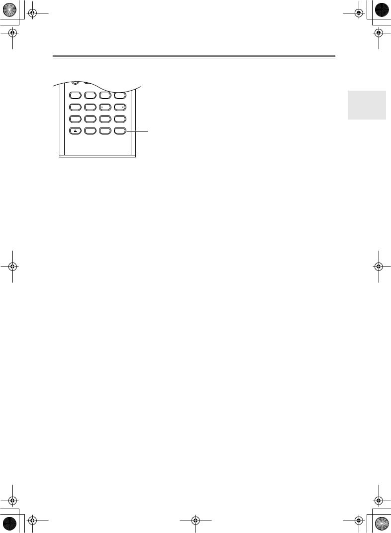
CD Mode
CD mode is used to control an Integra CD player connected to the AV receiver via 
 .
.
To set the remote controller to CD mode, press the [CD] Remote Mode button.
1On button
This button is used to set the CD player to On or Standby.
2Number buttons
These buttons are used to enter track numbers and to enter times for locating specific points in time.
3Disc button
This button is used to select discs on a CD changer.
4Display button
This button is used to display information about the current disc or track on the CD player’s display, including the elapsed time, remaining time, total time, and so on.
5Playback buttons
From left to right: Previous, Play, Next, Fast Reverse, Pause, Stop, and Fast Forward.
6Repeat button
This button is used to set the repeat playback functions.
7Open/Close [ ] button
This button is used to open and close the disc tray.
8Clear button
This button is used to cancel functions and to clear entered numbers.
9VOL button
This button is used to adjust the volume of the AV receiver.
0Muting button
This button is used to mute the AV receiver.
ARandom button
This button is used with the random playback function.
B Memory button
This button is used with the memory playback function, which allows you to create a custom playlist of tracks.
17
DTR-6.5,5.5_En.book Page 18 Wednesday, July 28, 2004 9:07 AM
Remote Controller—Continued
1 |
On |
Standby |
|
|
TV |
|
|||
|
|
|
|
|
|
|
|
||
|
|
|
|
|
I |
|
Input |
|
|
|
|
|
|
|
|
|
|
||
|
V1 |
|
V2 |
|
V3 |
|
|
|
|
|
1 |
|
2 |
|
3 |
|
+ |
|
|
|
V4 |
Multi CH |
DVD |
TV CH |
|
||||
2 |
4 |
|
5 |
|
6 |
|
- |
|
|
CD |
|
Tape |
Tuner |
|
|
||||
|
7 |
|
8 |
|
9 |
|
|
|
|
|
Phono |
|
|
|
|
|
|
TV VOL |
|
|
+10 |
|
0 |
|
Clear |
|
|
||
|
--/--- |
Input Selector |
|
|
|
J |
|||
|
|
|
|
|
|||||
|
|
Macro |
|
|
|
|
|||
|
1 |
|
2 |
|
3 |
|
Zone 2 |
|
|
|
|
|
Remote Mode |
|
|
|
|||
Tape |
Receiver |
|
DVD |
CD |
MD/CDR |
MD/CDR |
|||
|
Tape |
|
|
|
|
|
|
|
|
|
TV |
|
VCR |
Cable |
SAT |
|
|||
|
Dimmer |
|
|
|
|
|
|
Sleep |
|
|
|
|
|
|
u |
M |
|
|
|
|
TV |
|
en |
|
|
|
|||
|
|
pM |
|
en |
|
|
|||
|
Input |
o |
|
|
|
u |
|
|
|
|
T |
|
|
|
|
|
|
|
|
|
+ |
|
|
|
|
|
|
|
|
|
CH |
|
|
|
Enter |
|
VOL |
K5 |
|
|
Disc |
|
|
|
|
||||
|
- |
|
E |
|
|
e |
|
|
|
|
|
|
xit |
|
|
||||
|
|
|
id |
|
|
|
|||
|
Prev |
|
|
Gu |
|
|
|
||
|
R |
et |
|
|
|
p |
|
|
|
3 |
CH |
|
urn |
Se |
|
|
L6 |
||
Display |
|
|
|
|
|
|
Muting |
||
1 4 |
|
|
|
|
|
|
|
||
|
|
|
|
|
|
|
|
|
|
2 5 |
|
|
|
|
|
|
|
|
M7 |
3 6 |
Rec |
|
|
|
|
|
|
Random |
N8 |
4 7 |
|
|
|
|
|
|
|
|
O |
|
Audio |
Subtitle |
Angle |
Last Memory |
|
||||
|
Surround |
|
All ST |
THX |
Stereo |
|
|||
|
Repeat |
|
A-B |
|
Search |
Memory |
P |
||
8 |
Pure A |
|
Direct |
DSP |
DSP |
||||
|
|
|
|
|
|
|
|
||
|
Test Tone |
CH SEL |
Level- |
Level+ |
|
||||
9 |
Open/Close Video Off |
|
|
|
|
||||
|
|
|
|
|
L Night |
Re-EQ |
|
||
|
|
|
RC-585M |
|
|
|
|||
Round numbers are for MD/CDR mode.
Square numbers are for TAPE mode.
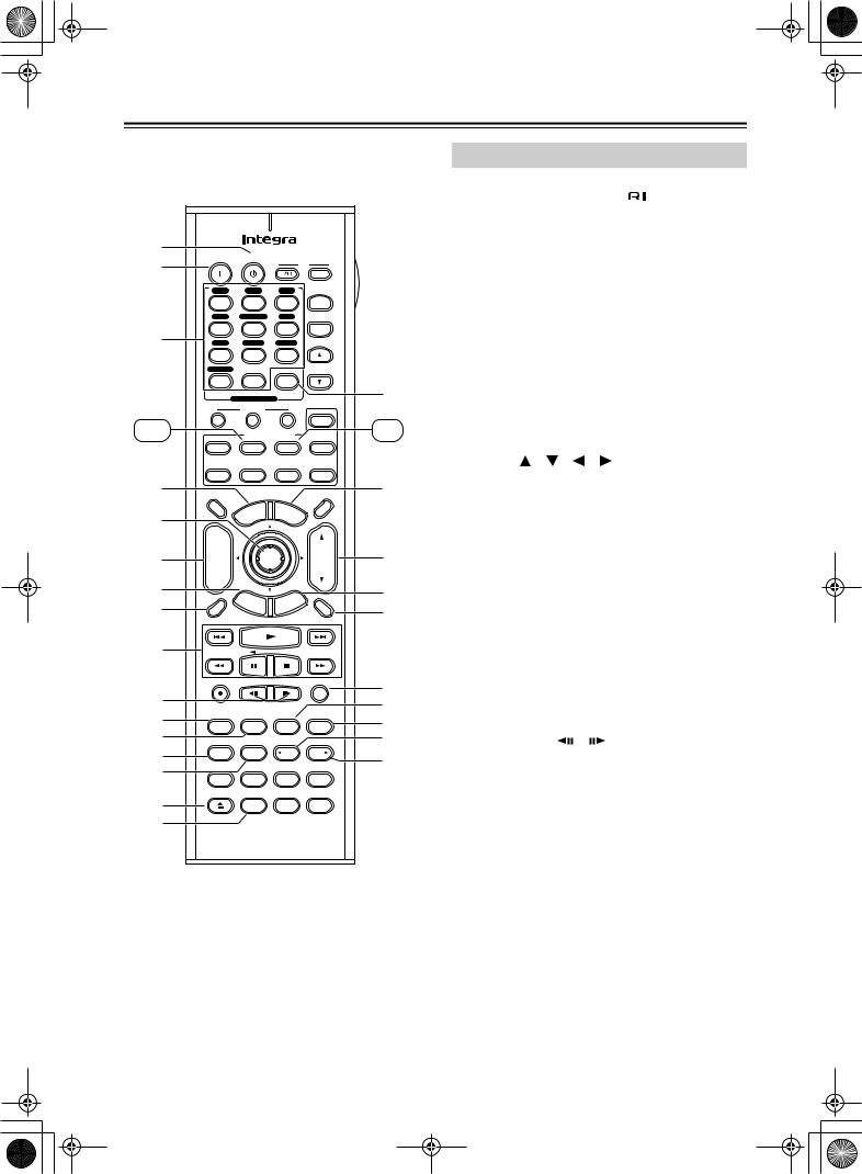
MD/CDR Mode
MD/CDR mode is used to control an Integra MiniDisc recorder or CD recorder connected to the AV receiver via 
 .
.
To select MD/CDR mode, press the [MD/CDR] Remote Mode button.
By default, this button is set to control a MiniDisc recorder. To control a CD recorder, it must be set to CDR (see page 80).
AOn button
This button is used to set the MD recorder or CD recorder to On or Standby.
BNumber buttons
These buttons are used to enter track numbers and to enter times for locating specific points in time.
CDisplay button
This button is used to display information about the current disc or track on the MD recorder or CDR recorder’s display, including the elapsed time, remaining time, total time, and so on.
DPlay [ ] button
This button is used to start playback.
EPrevious & Next [ ]/[
]/[
 ] buttons
The Previous [ ] button is used to select the previous track. During playback it selects the beginning of the current track. The Next [
 ] button is used to select the next track.
FPause [ 
 ] button
This button is used to pause playback.
GRec [ ] button
This button is used to start recording.
HRepeat button
This button is used to set the repeat playback functions.
IOpen/Close [ ] button
This button is used to eject a MiniDisc or to open and close the CD recorder’s disc tray.
JClear button
This button is used to cancel functions and to clear entered numbers.
KVOL button
This button is used to adjust the volume of the AV receiver.
LMuting button
This button is used to mute the AV receiver.
18
DTR-6.5,5.5_En.book Page 19 Wednesday, July 28, 2004 9:07 AM
Remote Controller—Continued
MFR & FF [ ]/[
]/[ ] buttons
The FR [ ] button is used to start fast reverse. The FF [
 ] button is used to start fast forward.
NStop [ ] button
This button is used to stop playback.
ORandom button
This button is used with the random playback function.
PMemory button
This button is used with the memory playback function, which allows you to create a custom playlist of tracks.
TAPE Mode
TAPE mode is used to control an Integra cassette recorder connected to the AV receiver via 
 .
.
To set the remote controller to TAPE mode, press the [Tape] Remote Mode button.
For double cassette decks, only Deck B can be controlled.
1Play [ ] button
This button is used to start playback.
2Previous & Next [ ]/[
]/[
 ] buttons
The Previous [ ] button is used to select the previous track. During playback it selects the beginning of the current track. The Next [
 ] button is used to select the next track.
The Previous and Next [ ]/[
]/[
 ] buttons may not work properly with some cassette tapes depending on how they were recorded.
3Reverse Play [ ] button
This button is used to start reverse playback.
4Rec [ ] button
This button is used to start recording.
5VOL button
This button is used to adjust the volume of the AV receiver.
6Muting button
This button is used to mute the AV receiver.
7Rewind & FF [ ]/[
]/[ ] buttons
The Rewind [ ] button is used to start rewind. The FF [
 ] button is used to start fast forward.
8Stop [ ] button
This button is used to stop playback.
19
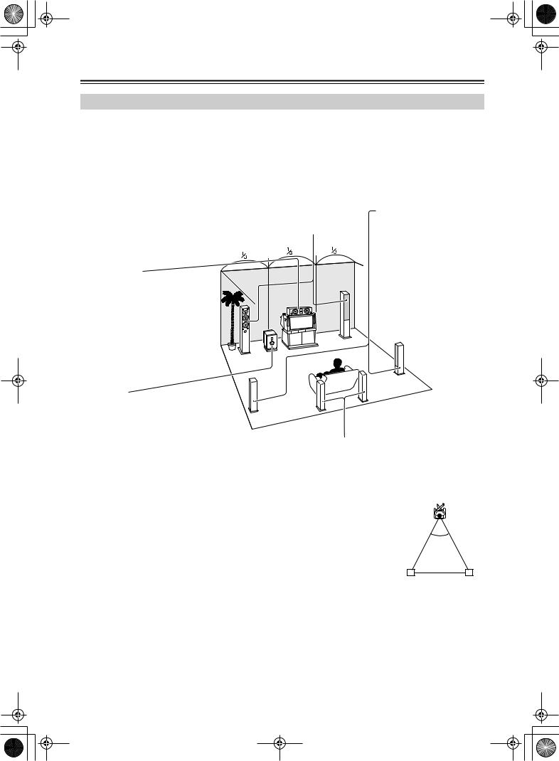
DTR-6.5,5.5_En.book Page 20 Wednesday, July 28, 2004 9:07 AM
About Home Theater
Enjoying Home Theater
Thanks to the AV receiver’s superb capabilities, you can enjoy surround sound with a real sense of movement in your own home—just like being in a movie theater or concert hall. With DVDs you can enjoy DTS and Dolby Digital. With analog and digital TV you can enjoy Dolby Pro Logic IIx or Onkyo’s own DSP surround listening modes.
With the DTR-6.5 you can enjoy DVDs that feature THX Surround EX (THX-certified THX speaker system recommended).
Front left and right speakers
These output the overall sound. Their role in a home theater is to provide a solid anchor for the sound image. They should be positioned facing the listener at about ear level, and equidistant from the TV. Angle them inward so as to create a triangle, with the listener at the apex.
Center speaker
This speaker enhances the front left and right speakers, making sound movements distinct and providing a full sound image. In movies it’s used mainly for dialog.
Position it close to your TV (preferably on top) facing forward at about ear level, or at the same height as the front left and right speakers.
Surround left and right speakers
These speakers are used for precise sound positioning and to add realistic ambience.
Position them at the sides of the listener, or slightly behind, about 2–3 feet (60–100 cm) above ear level. Ideally they should be equidistant from the listener.
Subwoofer
The subwoofer handles the bass sounds of the LFE (Low-Frequency Effects) channel. The volume and quality of the bass output from your subwoofer will depend on its position, the shape of your listening room, and your listening position. In general, a good bass sound can be obtained by installing the subwoofer in a front corner, or at one-third the width of the wall, as shown.
Tip: To find the best position for your subwoofer, while playing a movie or some music with good bass, experiment by placing your subwoofer at various positions within the room, and choose the one that provides the most satisfying results.
Surround back left and right speakers
These speakers are necessary to enjoy Dolby Digital EX, DTS-ES Matrix, DTS-ES Discrete, and THX Surround EX (DTR-6.5 only). They enhance the realism of surround sound and improve sound localization behind the listener. Position them behind the listener about 2–3 feet (60– 100 cm) above ear level.
For the DTR-6.5, THX recommends that they be placed equidistant from the listener, creating a triangle, and that the angle at the apex of the triangle is about 60 degrees.
Make sure that the listening position is within the range of the speakers.
|
|
|
60˚ |
||
|
|
|
|
||
|
|
|
|
|
|
Surround |
Surround |
||||
back left |
back right |
||||
speaker |
speaker |
||||
20
DTR-6.5,5.5_En.book Page 21 Wednesday, July 28, 2004 9:07 AM
Connecting the AV receiver
About AV Connections
•Before making any AV connections, read the manuals supplied with your other AV components.
•Don’t connect the power cord until you’ve completed and double-checked all AV connections.
Optical Digital Jacks
The AV receiver’s optical digital jacks have shutter-type covers that open when an optical plug is inserted and close when it’s removed. Push plugs in all the way.
Caution: To prevent shutter damage, hold the optical plug straight when inserting and removing.
AV Cables & Jacks
AV Connection Color Coding
RCA-type AV connections are usually color coded: red, white, and yellow. Use red plugs to connect rightchannel audio inputs and outputs (typically labeled “R”). Use white plugs to connect left-channel audio inputs and outputs (typically labeled “L”). And use yellow plugs to connect composite video inputs and outputs.
Right (red) |
Analog audio |
Right (red) |
|
||
Left (white) |
|
Left (white) |
(Yellow) |
Composite video |
(Yellow) |
|
• Push plugs in all the way to make |
|
|
|
|
|
Right! |
|
|||||||||
good connections (loose connec- |
|
|
|
|
|
|
|
|
|
|
|
|
|
|
|
|
tions can cause noise or malfunc- |
|
|
|
|
|
|
|
|
|
|
|
|
|
|
|
|
tions). |
|
|
|
|
|
|
|
|
|
|
|
|
|
|
|
|
• To prevent interference, keep |
|
|
|
|
|
|
|
|
|
|
|
|
|
|
|
|
|
|
|
|
|
Wrong! |
|
||||||||||
audio and video cables away from |
|
|
|
|
|
|
||||||||||
|
|
|
|
|
|
|||||||||||
power cords and speaker cables.
Video
Cable |
Jack |
Description |
|
PR |
PR |
Component video separates the luminance (Y) and |
|
|
|
Y |
color difference signals (PR, PB), providing the best |
|
Component |
PB |
PB |
||
video cable |
|
PB |
picture quality. (Some TV manufacturers label their |
|
Y |
Y |
|||
|
component video sockets slightly differently.) |
|||
|
|
PR |
||
|
|
|
S-Video separates the luminance and color signals |
|
S-Video cable |
|
S |
and provides better picture quality than composite |
|
|
|
|
video. |
|
Composite |
|
|
Composite video is commonly used on TVs, VCRs, |
|
|
V |
and other video equipment. Use only dedicated |
||
video cable |
|
|
||
|
|
composite video cables. |
||
|
|
|
||
Audio |
|
|
|
|
|
Cable |
Jack |
Description |
Optical digital |
Offers the best sound quality and allows you to |
|
OPTICAL |
||
enjoy surround sound (e.g., Dolby Digital, DTS). |
||
audio cable |
||
The audio quality is the same as for coaxial. |
||
|
|
|
Offers the best sound quality and allows you to |
|
Coaxial digital |
|
COAXIAL |
|
|
enjoy surround sound (e.g., Dolby Digital, DTS). |
||
audio cable |
|
||
|
The audio quality is the same as for optical. |
||
|
|
||
Analog audio |
L |
This cable carries analog audio. It’s the most |
|
|
common connection format for analog audio, and |
||
cable (RCA) |
R |
||
can be found on virtually all AV components. |
|||
|
|
||
|
|
This cable carries multichannel analog audio and |
|
Multichannel |
|
it’s typically used to connect DVD players with a |
|
|
5.1-channel analog audio output. Several standard |
||
analog audio |
|
||
cable (RCA) |
|
analog audio cables can be used instead of a multi- |
|
|
|
||
|
|
channel cable. |
21
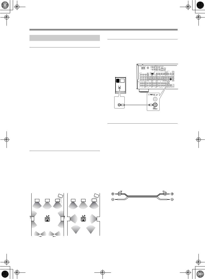
DTR-6.5,5.5_En.book Page 22 Wednesday, July 28, 2004 9:07 AM
Connecting the AV receiver—Continued
Connecting Your Speakers
Speaker Configuration
For the best surround-sound experience, you should connect seven speakers and a powered subwoofer.
The following table indicates the channels you should use depending on the number of speakers that you have.
Number of speakers: |
2 |
3 |
4 |
5 |
6 |
7 |
|
|
|
|
|
|
|
Front left |
|
|
|
|
|
|
|
|
|
|
|
|
|
Front right |
|
|
|
|
|
|
|
|
|
|
|
|
|
Center |
|
|
|
|
|
|
|
|
|
|
|
|
|
Surround left |
|
|
|
|
|
|
|
|
|
|
|
|
|
Surround right |
|
|
|
|
|
|
|
|
|
|
|
|
|
Surround back* |
|
|
|
|
|
|
|
|
|
|
|
|
|
Surround back left |
|
|
|
|
|
|
|
|
|
|
|
|
|
Surround back right |
|
|
|
|
|
|
|
|
|
|
|
|
|
*If you’re using only one surround back speaker, connect it to the left (L) SURROUND BACK SPEAKERS terminals.
No matter how many speakers you use, a powered subwoofer is recommended for a really powerful and solid bass.
To get the best from your surround-sound system, you need to set the speaker settings by using the supplied setup microphone (see page 39).
Using Dipole Speakers
You can use dipole speakers for the surround left and right and surround back left and right speakers. Dipole speakers output the same sound in two directions. Dipole speakers typically have an arrow printed on them to indicate how they should be positioned. The surround left and right dipole speakers should be positioned so that their arrows point toward the TV/screen, while the surround left and right dipolar speakers should be positioned so that their arrows point toward each other, as shown.
Dipole speakers |
|
|
Normal speakers |
|
||||
|
|
|
|
|
|
|
|
|
|
|
|
1 |
|
|
|
|
1 |
|
TV/screen |
|
|
TV/screen |
|
|||
2 |
3 |
4 |
2 |
3 |
4 |
5 |
6 |
5 |
6 |
|
|
7 |
|
8 |
|
|
7 |
|
8 |
|
|
1. Subwoofer |
|
|
6. Surround right speaker |
||||||||
2. Front left speaker |
7. Surround back left |
||||||||||
3. Center speaker |
|
|
|
speaker |
|
|
|||||
4. Front right speaker |
8. Surround back right |
||||||||||
5. Surround left speaker |
|
speaker |
|
|
|||||||
22
Connecting a Powered Subwoofer
Using a suitable cable, connect the AV receiver’s SUBWOOFER PRE OUT to an input on your powered subwoofer, as shown. If your subwoofer is unpowered and you’re using an external amplifier, connect the SUBWOOFER PRE OUT to an input on the amp.
Powered |
|
|
|
|
RS232 |
OPTICAL |
|
|
|
|
|
IN 2 |
IN 1 |
OUT |
|
|
|
|
|
|
|
IN4 |
IN3 |
IN2 |
IN1 |
OUT |
|
DIGITAL |
|
|
|
|
|
|
|
|
|
COAXIAL |
|
|||||
subwoofer |
|
COMPONENT VIDEO |
IN |
OUT |
IN |
OUT |
IN |
IN |
OUT |
FRONT |
SURR |
CENTER |
SURR BACK |
|
|
IN 3 |
IN 2 |
IN 1 |
OUT |
|
|
|
|
|
|
|
|
|
|
|
Y |
|
|
VIDEO 3 |
VIDEO 2 |
|
VIDEO 1 |
DVD |
MONITOR |
|
PRE OUT |
|
||
|
|
|
|
|
|
|
||||||||
|
|
|
|
|
|
|
|
|
|
V |
|
L |
|
|
P |
L |
|
S |
P |
R |
|
|
SUB |
|
|
ER |
IN |
IN |
OUT |
L |
|
|
GND |
|
|
|
|
REMOTE |
R |
|
CONTROL |
PHONO |
CD |
|
LINE INPUT
Attaching the Speaker Labels
The AV receiver’s positive (+) speaker terminals are color-coded for ease of identification. (The negative (–) speaker terminals are all black.)
Speaker terminal |
Color |
|
|
Front left, Zone 2 left |
White |
|
|
Front right, Zone 2 right |
Red |
|
|
Center |
Green |
|
|
Surround left |
Blue |
|
|
Surround right |
Gray |
|
|
Surround back left |
Brown |
|
|
Surround back right |
Tan |
|
|
The supplied speaker labels are also color-coded and you should attach them to the positive (+) side of each speaker cable in accordance with the above table. All you need to do then is to match the color of each label to the corresponding speaker terminal.
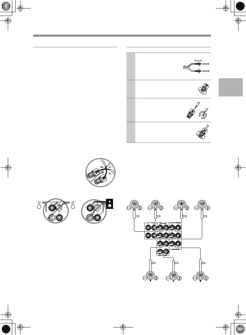
DTR-6.5,5.5_En.book Page 23 Wednesday, July 28, 2004 9:07 AM
Connecting the AV receiver—Continued
Speaker Connection Precautions
Read the following before connecting your speakers:
•American model only: Only connect speakers with an impedance of 6 ohms or higher. If you use speakers with a lower impedance, and use the amplifier at high volume levels for a long period of time, the built-in protection circuit may be activated.
•Other models: You can connect speakers with an impedance of between 4 and 16 ohms. If the impedance of any of the connected speakers is 4 ohms or more, but less than 6 ohms, be sure to set the Minimum Speaker Impedance to “4 ohms” (see page 44). If you use speakers with a lower impedance, and use the amplifier at high volume levels for a long period of time, the built-in protection circuit may be activated.
•Disconnect the power cord from the wall outlet before making any connections.
•Read the instructions supplied with your speakers.
•Pay close attention to speaker wiring polarity. In other words, connect positive (+) terminals to only positive
(+) terminals, and negative (–) terminals to only negative (–) terminals. If you get them the wrong way around, the sound will be out of phase and will sound unnatural.
•Unnecessarily long, or very thin speaker cables may affect the sound quality and should be avoided.
•Be careful not to short the
positive and negative wires. Doing so may damage the AV receiver.
•Don’t connect more than one cable to each speaker terminal. Doing so may damage the AV receiver.
•Don’t connect one speaker to several terminals.
Connecting the Speaker Cables
1 |
Strip about 5/8" (15 mm) |
5/8" (15 mm) |
|
of insulation from the |
|
|
ends of the speaker |
|
|
cables, and twist the bare |
|
|
wires tightly, as shown. |
|
2 |
Unscrew the terminal. |
|
3 |
Fully insert the bare |
|
|
wires. |
|
4 |
Screw the terminal tight. |
|
The following illustration shows which speaker should be connected to each pair of terminals.
If you’re using only one surround back speaker, connect it to the left (L) SURROUND BACK SPEAKERS terminals.
Surround |
Surround |
Surround |
Surround |
||||||||||||||||||||||||||||||||||||||||
back left |
back right |
left |
right |
||||||||||||||||||||||||||||||||||||||||
speaker |
speaker |
speaker |
speaker |
||||||||||||||||||||||||||||||||||||||||
|
|
|
|
|
|
|
|
|
|
|
|
|
|
|
|
|
|
|
|
|
|
|
|
|
|
|
|
|
|
|
|
|
|
|
|
|
|
|
|
|
|
|
|
|
|
|
|
|
|
|
|
|
|
|
|
|
|
|
|
|
|
|
|
|
|
|
|
|
|
|
|
|
|
|
|
|
|
|
|
|
|
|
|
|
|
|
|
|
|
|
|
|
|
|
|
|
|
|
|
|
|
|
|
|
|
|
|
|
|
|
|
|
|
|
|
|
|
|
|
|
|
|
|
|
|
|
|
|
|
|
|
|
|
|
|
|
|
|
|
|
|
|
|
|
|
|
|
|
|
|
|
|
|
|
|
|
|
|
|
|
|
|
|
|
|
|
|
|
|
|
|
|
|
|
|
|
|
|
|
|
|
|
|
|
|
|
|
|
|
|
|
|
|
|
|
|
|
|
|
|
|
|
|
|
|
|
|
|
|
|
|
|
|
|
|
|
|
|
|
|
|
|
|
|
|
|
|
|
|
|
|
|
|
|
|
|
|
|
|
|
|
|
|
|
|
|
|
|
|
|
|
|
|
|
|
|
|
|
|
|
|
|
|
|
|
|
|
|
|
|
|
|
|
|
|
|
|
|
|
|
|
|
|
|
|
|
|
|
|
|
|
|
|
|
|
|
|
|
|
|
|
|
|
|
|
|
|
|
|
|
|
|
|
|
|
|
|
|
|
|
|
|
|
|
|
|
|
|
|
|
|
|
|
|
|
|
|
|
|
|
|
|
|
|
|
|
|
|
|
|
|
|
|
|
|
|
|
|
|
|
|
|
|
|
|
|
|
|
|
|
|
|
|
|
|
|
|
|
|
|
|
|
|
|
|
|
|
|
|
|
|
|
|
|
|
|
|
|
|
|
|
|
|
|
|
|
|
|
|
|
|
|
|
|
|
|
|
|
|
|
|
|
|
|
|
|
|
|
|
|
|
|
|
|
|
|
|
|
|
|
|
|
|
|
|
|
|
|
|
|
|
|
|
|
|
|
|
|
|
|
|
|
|
|
|
|
|
|
|
|
|
|
|
|
|
|
|
|
|
|
|
|
|
|
|
|
|
|
|
|
|
|
|
|
|
|
|
|
|
|
|
|
|
|
|
|
|
|
|
|
|
|
|
|
|
|
|
|
|
|
|
|
|
|
|
|
|
|
|
|
|
|
|
|
|
|
|
|
|
|
|
|
|
|
|
|
|
|
|
|
|
|
|
|
|
|
|
|
|
|
|
|
|
|
|
|
|
|
|
|
|
|
|
|
|
|
|
|
|
|
|
|
|
|
|
|
|
|
|
|
|
|
|
|
|
|
|
|
|
|
|
|
|
|
|
|
|
|
|
|
|
|
|
|
|
|
|
|
|
|
|
|
|
|
|
|
|
|
|
|
|
|
|
|
|
|
|
|
|
|
|
|
|
|
|
|
|
|
|
|
|
|
|
|
|
|
|
|
|
|
|
|
|
|
|
|
|
|
|
|
|
|
|
|
|
|
|
|
|
|
|
|
|
|
|
|
|
|
|
|
|
|
|
|
|
|
|
|
|
|
|
|
|
|
|
|
|
|
|
|
|
|
|
|
|
|
|
|
|
|
|
|
|
|
|
|
|
|
|
|
|
|
|
|
|
|
|
|
|
|
|
|
|
|
|
|
|
|
|
|
|
|
|
|
|
|
|
|
|
|
|
|
|
|
|
|
|
|
|
|
|
|
|
|
|
|
|
|
|
|
|
|
|
|
|
|
|
|
|
|
|
|
|
|
|
|
|
|
|
|
|
|
|
|
|
|
|
|
|
|
|
|
|
|
|
|
|
|
|
|
|
|
|
|
|
|
|
|
|
|
|
|
|
|
|
|
|
|
|
|
|
|
|
|
|
|
|
|
|
|
|
|
|
|
|
|
|
|
|
|
|
|
|
|
|
|
|
|
|
|
|
|
|
|
|
|
|
|
|
|
|
|
|
|
|
|
|
|
|
|
|
|
|
|
|
|
|
|
|
|
|
|
|
|
|
|
|
|
|
|
|
|
|
|
|
|
|
|
|
|
|
|
|
|
|
|
|
|
|
|
|
|
|
|
|
|
|
|
|
|
|
|
|
Front left |
|
|
Front right |
Center |
|||||||||||||||||||||||||||||||
|
|
|
|
speaker |
|
|
speaker |
speaker |
|||||||||||||||||||||||||||||||
23

DTR-6.5,5.5_En.book Page 24 Wednesday, July 28, 2004 9:07 AM
Connecting the AV receiver—Continued
Connecting Antenna
This section explains how to connect the supplied indoor FM antenna and AM loop antenna, and how to connect commercially available outdoor FM and AM antennas. The AV receiver won’t pick up any radio signals without any antenna connected, so you must connect the antenna to use the tuner.
 AM antenna push terminals
FM antenna connector
|
ZONE 2 SPEAKERS |
SURROUND BACK |
SURROUND SPEAKERS |
|
SPEAKERS |
||
|
|
|
L |
|
L |
|
|
4 |
DIGITAL |
|
|
COAXIAL |
|
|
RS232 |
OPTICAL |
2 |
R |
COMPONENT VIDEO |
|
|
|
|
|
|
R |
Y
VIDEO 3 |
VIDEO 2 |
VIDEO 1 |
DVD |
OUT |
PRE OUT |
|
|
|
|
MONITOR |
|
|
|
|
|
|
|
V |
L |
|
|
P |
|
|
|
|
|
|
|
L |
L |
|
|
|
|
|
|
S |
|
|
|
P |
|
|
|
|
|
|
|
R |
|
|
|
|
|
|
|
|
R |
SUB |
CENTER SPEAKER |
|
|
|
|
|
|
|
|
WOOFER |
R |
GND L |
|
|
|
|
|
|
|
|
FRONT SPEAKERS |
R |
|
|
|
|
|
|
|
|
|
|
|
|
|
|
|
|
SUB |
SUB |
|
PHONO |
CD |
TAPE |
VIDEO 3 |
VIDEO 2 |
VIDEO 1 |
DVD |
WOOFER |
WOOFER |
|
Connecting the Indoor FM Antenna
The supplied indoor FM antenna is for indoor use only.
1 Attach the FM antenna, as shown.
■ American Model
Insert the plug fully into the jack.
■ Other Models
Insert the plug fully into the jack.
Once your AV receiver is ready for use, you’ll need to tune into an FM radio station and adjust the position of the FM antenna to achieve the best possible reception.
2 Use thumbtacks or something similar to fix the FM antenna into position.
Thumbtacks, etc.
If you cannot achieve good reception with the supplied indoor FM antenna, try a commercially available outdoor FM antenna instead (see page 25).
Connecting the AM Loop Antenna
The supplied indoor AM loop antenna is for indoor use only.
1 Assemble the AM loop antenna, inserting the tabs into the base, as shown.
2 Connect both wires of the AM loop antenna to the AM push terminals, as shown.
(The antenna’s wires are not polarity sensitive, so they can be connected either way around). Make sure that the wires are attached securely and that the push terminals are gripping the bare wires, not the insulation.
Push |
Insert wire |
Release |
Once your AV receiver is ready for use, you’ll need to tune into an AM radio station and adjust the position of the AM antenna to achieve the best possible reception.
Keep the antenna as far away as possible from your AV receiver, TV, speaker cables, and power cords.
If you cannot achieve good reception with the supplied indoor AM loop antenna, try using it with a commercially available outdoor AM antenna (see page 25).
Caution: Be careful that you don’t injure yourself when using thumbtacks.
24
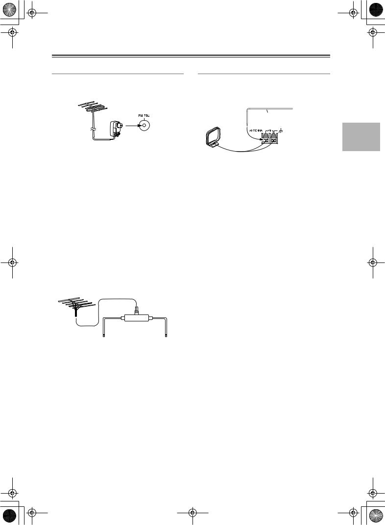
DTR-6.5,5.5_En.book Page 25 Wednesday, July 28, 2004 9:07 AM
Connecting the AV receiver—Continued
Connecting an Outdoor FM Antenna
If you cannot achieve good reception with the supplied indoor FM antenna, try a commercially available outdoor FM antenna instead.
Connecting an Outdoor AM Antenna
If good reception cannot be achieved using the supplied AM loop antenna, an outdoor AM antenna can be used in addition to the loop antenna, as shown.
Outdoor antenna
Insulated antenna cable
AM loop antenna
Notes:
•Outdoor FM antennas work best outside, but usable results can sometimes be obtained when installed in an attic or loft.
•For best results, install the outdoor FM antenna well away from tall buildings, preferably with a clear line of sight to your local FM transmitter.
•Outdoor antenna should be located away from possible noise sources, such as neon signs, busy roads, etc.
•For safety reasons, outdoor antenna should be situated well away from power lines and other high-voltage equipment.
•Outdoor antenna must be grounded in accordance with local regulations to prevent electrical shock hazards.
■ Using a TV/FM Antenna Splitter
Outdoor AM antennas work best when installed outside horizontally, but good results can sometimes be obtained indoors by mounting horizontally above a window. Note that the AM loop antenna should be left connected.
Outdoor antenna must be grounded in accordance with local regulations to prevent electrical shock hazards.
It’s best not to use the same antenna for both FM and TV reception, as this can cause interference problems. If circumstances demand it, use a TV/FM antenna splitter, as shown.
TV/FM antenna splitter
To AV receiver |
To TV (or VCR) |
25
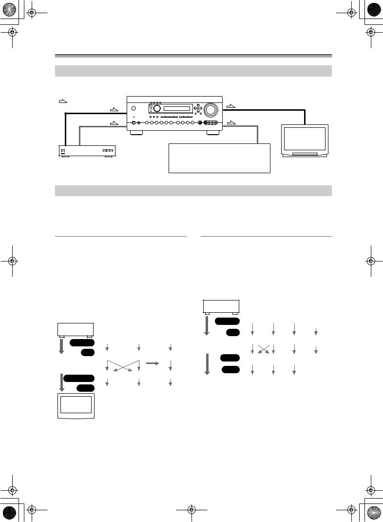
DTR-6.5,5.5_En.book Page 26 Wednesday, July 28, 2004 9:07 AM
Connecting the AV receiver—Continued
Connecting Both Audio & Video
By connecting both the audio and video outputs of your DVD player and other AV components to the AV receiver, you can select both the audio and video simultaneously simply by selecting the appropriate input source on the AV receiver.
: Signal Flow
Video |
Video |
Audio |
Audio |
|
TV, projector, |
|
etc. |
|
|
|
|
|
|
|
|
|
|
|
|
|
|
|
|
|
|
|
|
|
|
|
|
|
|
|
|
|
|
|
|
|
|
|
|
|
|
|
|
|
|
|
|
|
|
|
|
|
|
|
|
|
|
|
|
|
|
|
|
|
|
|
|
|
|
|
|
|
|
|
|
|
|
|
|
|
|
|
|
|
|
|
|
|
|
|
|
|
|
|
|
|
|
|
|
|
|
|
|
|
|
|
|
|
|
|
|
DVD player, etc. |
|
Speakers (see page 23 for connection |
||||||||||||||||||||||||
|
|
|
|
|
|
|
|
information) |
||||||||||||||||||
Which Connections Should I Use?
The AV receiver supports several connection formats for compatibility with a wide range of AV equipment. The format you choose will depend on the formats supported by your other components. Use the following sections as a guide. For video components, you must make two connections—one for audio, one for video.
Video Connection Formats
Video equipment can be connected to the AV receiver by using any one of the following video connection formats: composite video, S-Video, or component video, the latter offering the best picture quality.
A video signal connected to a V or S IN jack will be con- verted—composite video to S-Video or S-Video to composite video—but only for the MONITOR OUT jacks, not the VIDEO 1 and VIDEO 2 OUT V and S jacks. Note: The DTR-6.5/5.5 can be set to upconvert composite video and S-Video input signals and output them from the COMPONENT VIDEO OUT (see page 43).
DVD player, etc.
|
|
|
|
|
Output |
Composite |
S-Video |
Component |
||||||
|
|
|
|
|
|
|
|
|||||||
|
|
|
|
|
|
IN |
Composite |
S-Video |
Component |
|||||
|
|
|
|
|
|
|
|
|
|
|
|
|
||
|
|
AV Receiver |
|
page 43 |
* |
|||||||||
|
|
|
|
|
|
|
|
|
|
|
|
|
||
|
|
|
|
MONITOR OUT |
Composite |
S-Video |
Component |
|||||||
|
|
|
|
|
|
|
||||||||
|
|
|
|
|
Input |
Composite |
S-Video |
Component |
||||||
|
|
|
|
TV, pro- |
|
|
|
|||||||
|
|
|
|
|
jector, |
|
|
|
||||||
|
|
|
|
|
etc. |
|
|
|
||||||
|
|
|
|
|
|
|
|
|
|
|
|
|
|
|
|
|
|
|
|
|
|
|
|
|
|
|
|
|
|
Audio Connection Formats
Audio equipment can be connected to the AV receiver by using any of the following audio connection formats: analog, optical, coaxial, or multichannel.
When choosing a connection format, bear in mind that the AV receiver doesn’t convert between them. For example, audio signals connected to an OPTICAL or COAXIAL input are not output by the analog TAPE OUT.
DVD player, etc.
|
|
|
|
Output |
Optical |
Coaxial |
Analog |
Multi- |
||||
|
|
|
|
|
|
|
channel |
|||||
|
|
|
|
IN |
|
|
|
|
||||
|
|
|
|
|
|
|
|
|
Optical |
Coaxial |
Analog |
Multi- |
|
|
AV Receiver |
||||||||||
|
|
|
|
|
channel |
|||||||
|
|
|
|
|
|
|
|
|
|
Coaxial * |
|
|
|
|
|
|
OUT |
Optical |
Analog |
Only front |
|||||
|
|
|
|
|
|
|
|
|
|
|
|
left and |
|
|
|
|
Input |
|
|
|
right |
||||
|
|
|
|
|
|
|
|
|||||
|
|
|
|
|
|
|
|
|
Optical |
Coaxial |
Analog |
|
|
MD recorder, |
|
||||||||||
|
|
|
|
|
||||||||
|
|
|
|
etc. |
|
|
|
* DTR-6.5 only |
||||
|
|
|
|
|
|
|
|
|
|
|
|
|
26
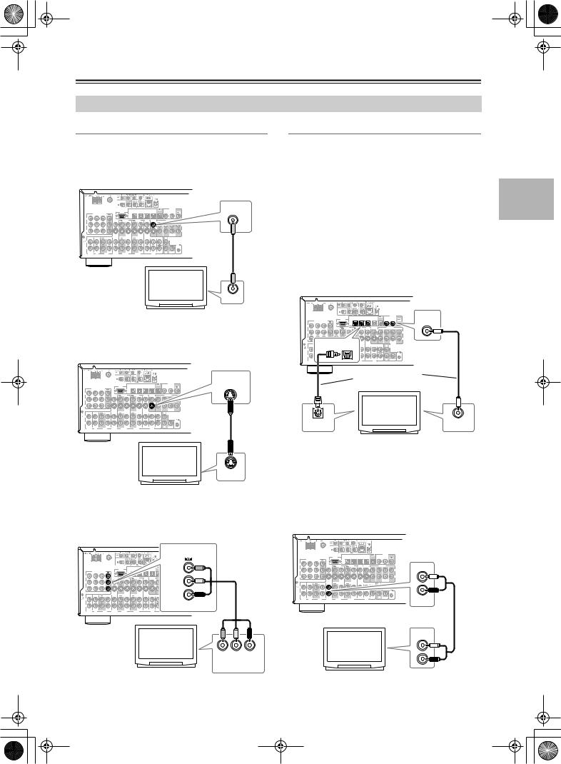
DTR-6.5,5.5_En.book Page 27 Wednesday, July 28, 2004 9:07 AM
Connecting the AV receiver—Continued
Connecting Your TV or Projector
Monitor Out
■ Using Composite Video
Use a composite video cable to connect the AV receiver’s V MONITOR OUT jack to a composite video input on your TV, as shown.
|
|
|
|
|
|
|
IN4 |
IN3 |
IN2 |
IN1 |
|
OUT |
|
|
COAXIAL |
|
MONITOR |
|
|
|
|
|
|
|
|
|
|
|
|
|
|
|
DIGITAL |
|
OUT |
IN 3 |
IN 2 |
IN 1 |
OUT |
|
RS232 |
OPTICAL |
|
|
|
|
|
|
|
IN 2 |
IN 1 |
OUT |
|
|
COMPONENT VIDEO |
|
|
|
|
|
|
|
|
|
|
|
|
|
|
|
|
Y |
|
|
|
VIDEO 3 |
VIDEO 2 |
|
VIDEO 1 |
DVD |
MONITOR |
|
|
PRE OUT |
|
V |
|||
|
|
|
|
|
|
|
|
||||||||||
|
|
|
|
IN |
OUT |
IN |
OUT |
IN |
IN |
OUT |
V |
FRONT |
L |
SURR |
CENTER |
SURR BACK |
|
P |
|
|
|
|
|
|
|
|
|
|
|
|
|
|
|
|
L |
|
|
|
|
|
|
|
|
|
|
|
S |
|
|
|
|
|
|
P |
|
|
|
|
|
|
|
|
|
|
|
|
|
|
|
|
R |
|
|
|
|
|
|
|
|
|
|
|
|
|
R |
|
SUB |
|
|
|
|
|
|
|
|
|
|
|
|
|
|
|
|
|
WOOFER |
|
|
IN |
IN |
OUT |
IN |
IN |
OUT |
IN |
OUT |
IN |
FRONT |
SURR |
|
CENTER |
|
L |
ZONE 2 |
|
|
|
|
|
|
|
|
|
OUT |
|
|
||||||||
L |
|
|
|
|
|
|
|
|
|
|
|
|
|
|
|
|
|
GND |
|
|
|
|
|
|
|
|
|
|
|
|
|
|
|
|
|
|
|
|
|
|
|
|
|
|
|
|
|
|
|
|
|
REMOTE |
|
R |
|
|
|
|
|
|
|
|
|
|
|
|
|
|
|
CONTROL |
|
|
|
|
|
|
|
|
|
|
|
|
|
SUB |
|
R |
SUB |
|
|
PHONO |
CD |
TAPE |
|
VIDEO 3 |
VIDEO 2 |
|
VIDEO 1 |
|
DVD |
|
WOOFER |
|
|
WOOFER |
|
|
|
TV, projector, etc.
VIDEO IN
■ Using S-Video
Use an S-Video cable to connect the AV receiver’s
S MONITOR OUT jack to an S-Video input on your TV, as shown.
|
|
|
|
|
|
|
|
|
|
|
|
|
MONITOR |
|
|
|
|
|
|
|
|
|
|
|
|
|
OUT |
|
|
|
|
|
|
|
IN4 |
IN3 |
IN2 |
|
|
|
|
|
COMPONENT VIDEO |
|
|
RS232 |
OPTICAL |
|
|
|
|
|
|
|
|
|
OUT |
|
|
|
|
|
|
|
|
|
|
||
IN 3 |
IN 2 |
IN 1 |
|
|
|
|
|
|
|
|
|
|
|
Y |
|
|
|
VIDEO 3 |
VIDEO 2 |
|
VIDEO 1 |
DVD |
|
|
|
S |
|
|
|
|
|
|
|
|
|
||||||
|
|
|
|
IN |
OUT |
IN |
OUT |
IN |
IN |
|
|
|
|
P |
|
|
|
|
|
|
|
|
|
|
|
|
|
P |
|
|
|
|
|
|
|
|
|
|
|
|
|
|
|
|
|
|
|
|
|
|
|
|
|
|
WOOFER |
IN |
IN |
OUT |
IN |
IN |
OUT |
IN |
OUT |
IN |
FRONT |
SURR |
CENTER |
L |
ZONE 2 |
|
|
|
|
|
OUT |
||||||||
L |
|
|
|
|
|
|
|
|
|
|
|
|
|
GND |
|
|
|
|
|
|
|
|
|
|
|
|
|
|
|
|
|
|
|
|
|
|
|
|
|
|
REMOTE |
R |
|
|
|
|
|
|
|
|
|
|
|
|
CONTROL |
|
|
|
|
|
|
|
|
|
|
|
SUB |
R |
SUB |
PHONO |
CD |
TAPE |
|
VIDEO 3 |
VIDEO 2 |
|
VIDEO 1 |
|
DVD |
WOOFER |
|
WOOFER |
|
Audio Connections
These connections will allow you to listen to audio from your TV via the AV receiver.
If your TV doesn’t have an audio output, connect the AV receiver to your VCR and use its tuner (see page 30).
■ Using Coaxial or Optical Connections
If you connect to a digital audio input, you’ll need to assign it (see page 42).
•Use an optical digital audio cable to connect one of the AV receiver’s OPTICAL DIGITAL IN jacks to an optical output on your TV, as shown.
OR
•Use a coaxial digital audio cable to connect one of the AV receiver’s COAXIAL DIGITAL IN jacks to a coaxial output on your TV, as shown.
RS232 |
OPTICAL |
|
|
|
|
IN 2 |
|
COAXIAL |
|
IN4 |
IN3 |
IN2 |
IN1 |
OUT |
|
C |
|
COMPONENT VIDEO |
|
|
|
|
|
|
|
IN |
IN 3 |
|
|
|
|
|
|
|
|
Y |
|
|
|
|
|
|
|
|
DVD |
MONITOR |
|
PRE OUT |
IN |
OUT |
FRONT |
SURR |
|
|
|
|
V |
L |
|
P |
|
|
|
|
|
|
|
|
|
|
S |
|
|
P |
|
|
|
|
|
|
|
|
|
|
|
R |
SUB |
|
|
IN |
|
|
|
WOOFER |
|
OPTICAL |
SURR |
CENTER |
L |
ZONE 2 |
|
|
FRONT |
|
OUT |
|||
L |
|
|
|
|
|
|
GND |
|
|
|
|
|
|
|
|
|
|
|
|
REMOTE |
R |
|
|
|
|
|
CONTROL |
|
|
|
|
SUB |
R |
SUB |
|
|
|
DVD |
WOOFER |
|
WOOFER |
|
Connect one or the |
|
other |
|
TV, projector, |
|
etc. |
DIGITAL OUT |
DIGITAL OUT |
OPTICAL |
COAXIAL |
TV, projector, etc.
S VIDEO IN
■ Using Component Video
Use a component video cable to connect the AV receiver’s COMPONENT VIDEO OUT jacks to a component video input on your TV, as shown.
■ Using Analog Connections
If your TV doesn’t have a digital audio output, or you want to record from it, you’ll need to make the following analog audio connection.
Use an analog audio cable to connect the AV receiver’s VIDEO 3 IN L/R jacks to an analog audio output on your TV, as shown.
COMPONENT VIDEO
|
|
|
IN4 |
IN3 |
IN2 |
IN1 |
OUT |
DIGITAL |
|
|
|
COAXIAL |
|||||
|
COMPONENT VIDEO |
OUT |
|
|
|
|
|
|
IN 3 |
IN 2 |
IN 1 |
|
|
|
|
|
|
Y |
|
|
|
|
|
|
|
|
Y |
IN |
|
|
P |
|
COMPONENT VIDEO |
|
IN 3 |
IN 2 |
IN 1 |
Y |
|
|
|
P |
|
|
PB |
P |
|
|
|
IN |
IN |
OUT |
PR |
L |
|
|
|
GND |
|
|
|
R |
|
|
|
PHONO |
CD |
|
TAPE |
P
IN |
IN |
OUT |
IN |
L |
|
|
|
GND |
|
|
|
R |
|
|
|
PHONO |
CD |
|
TAPE |
VIDEO 3
TV, projector, etc.
Y PB PR
COMPONENT
VIDEO IN
TV, projector, etc.
AUDIO
OUTPUT
L
R
27
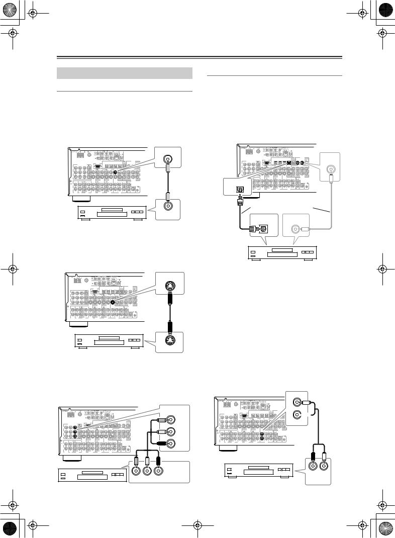
DTR-6.5,5.5_En.book Page 28 Wednesday, July 28, 2004 9:07 AM
Connecting the AV receiver—Continued
Connecting a DVD Player
Video Connections
You only need to use one of the following connection methods.
■ Using Composite Video
Use a composite video cable to connect the AV receiver’s V DVD IN jack to the composite video output on your DVD player, as shown.
Audio Connections
■ Using Coaxial or Optical Connections
•Use an optical digital audio cable to connect one of the AV receiver’s OPTICAL DIGITAL IN jacks to the
optical output on your DVD player, as shown. OR
•Use a coaxial digital audio cable to connect one of the AV receiver’s COAXIAL DIGITAL IN jacks to the coaxial output on your DVD player, as shown.
|
|
DVD |
|
|
IN |
|
IN4 |
IN3 |
RS232 |
OPTICAL |
|
COMPONENT VIDEO
IN 3 |
IN 2 |
IN 1 |
OUT |
|
|
|
|
|
|
|
|
|
|
Y |
|
|
|
VIDEO 3 |
VIDEO 2 |
|
VIDEO 1 |
|
|
|
|
|
|
|
|
|
|
IN |
OUT |
IN |
OUT |
IN |
|
|
|
|
|
P |
|
|
|
|
|
|
|
|
|
|
|
|
|
|
|
|
|
|
|
|
|
|
|
|
S |
|
|
P |
|
|
|
|
|
|
|
|
|
|
|
|
R |
|
|
|
|
|
|
|
|
|
|
|
|
R |
SUB |
|
|
|
|
|
|
|
|
|
|
|
|
|
WOOFER |
IN |
IN |
OUT |
IN |
IN |
OUT |
IN |
OUT |
IN |
FRONT |
SURR |
CENTER |
L |
ZONE 2 |
|
|
|
|
|
OUT |
||||||||
L |
|
|
|
|
|
|
|
|
|
|
|
|
|
GND |
|
|
|
|
|
|
|
|
|
|
|
|
|
|
|
|
|
|
|
|
|
|
|
|
|
|
REMOTE |
R |
|
|
|
|
|
|
|
|
|
|
|
|
CONTROL |
|
|
|
|
|
|
|
|
|
|
|
SUB |
R |
SUB |
PHONO |
CD |
|
TAPE |
VIDEO 3 |
VIDEO 2 |
|
VIDEO 1 |
|
|
DVD |
WOOFER |
|
WOOFER |
VIDEO OUT
DVD player
■ Using S-Video
Use an S-Video cable to connect the AV receiver’s S DVD IN jack to the S-Video output on your DVD player, as shown.
|
|
|
|
|
|
DIGITAL |
IN4 |
IN3 |
IN2 |
IN1 |
OUT |
C |
COAXIAL |
|
|
|
|
IN 2 |
|
|
|
|
|
|
|
|
IN |
PRE OUT
FRONT |
SURR |
|
V |
L |
|
S |
|
|
|
R |
SUB |
|
|
WOO |
CENTER |
L |
ZONE |
|
OUT |
|
IN1 |
|
|
OPTICAL |
|
|
SUB |
R |
SUB |
WOOFER |
|
WOOFER |
Connect one or the other
DIGITAL OUT |
DIGITAL OUT |
OPTICAL |
COAXIAL |
DVD player
|
|
DVD |
|
|
IN |
|
IN4 |
IN3 |
RS232 |
OPTICAL |
|
COMPONENT VIDEO
IN 3 |
IN 2 |
IN 1 |
OUT |
|
|
|
|
|
|
|
|
|
|
Y |
|
|
|
VIDEO 3 |
VIDEO 2 |
|
VIDEO 1 |
|
|
|
|
|
|
|
|
|
|
|
|
|
|
|
|
|
|||
|
|
|
|
IN |
OUT |
IN |
OUT |
IN |
|
|
|
|
|
P |
|
|
|
|
|
|
|
|
|
|
|
|
|
P |
|
|
|
|
|
|
|
|
|
|
|
|
|
|
|
|
|
|
|
|
|
|
|
|
|
|
SUB |
|
|
|
|
|
|
|
|
|
|
|
|
|
WOOFER |
IN |
IN |
OUT |
IN |
IN |
OUT |
IN |
OUT |
IN |
FRONT |
SURR |
CENTER |
L |
ZONE 2 |
|
|
|
|
|
OUT |
||||||||
L |
|
|
|
|
|
|
|
|
|
|
|
|
|
GND |
|
|
|
|
|
|
|
|
|
|
|
|
|
|
|
|
|
|
|
|
|
|
|
|
|
|
REMOTE |
R |
|
|
|
|
|
|
|
|
|
|
|
|
CONTROL |
|
|
|
|
|
|
|
|
|
|
|
SUB |
R |
SUB |
PHONO |
CD |
|
TAPE |
VIDEO 3 |
VIDEO 2 |
|
VIDEO 1 |
|
|
DVD |
WOOFER |
|
WOOFER |
S VIDEO OUT
DVD player
■ Using Component Video
Use a component video cable to connect the AV receiver’s COMPONENT VIDEO IN1 jacks to the component video output on your DVD player, as shown.
• Your TV must also be connected via component video.
Initially, the OPTICAL IN1 jack is assigned to the DVD input source. If you connect your DVD player to a different digital input, you’ll need to reassign the DVD input source (see page 42).
■ Using Analog Connections
Even if your DVD player is connected digitally (optical or coaxial), to use 
 , or to record audio from your DVD player, you’ll need to make an analog connection as well.
Use an analog audio cable to connect the AV receiver’s DVD IN L/R jacks to the analog audio output on your DVD player, as shown.
If your DVD player has stereo (L/R) and multichannel outputs, be sure to use the left and right outputs.
FRONT
COMPONENT VIDEO |
|
|
|
|
|
|
|
|
|
DIGITAL |
|
|
|
|
|
IN4 |
IN3 |
IN2 |
IN1 |
OUT |
|
|
|
IN1 |
|
|
|
|
COAXIAL |
|
|||||
COMPONENT VIDEO |
RS232 |
OPTICAL |
|
|
|
|
IN 2 |
IN 1 |
OUT |
||
OUT |
|
|
|
|
|
|
|
|
|||
IN 3 |
IN 2 |
IN 1 |
|
|
|
|
|
|
|
|
|
Y |
|
|
|
|
|
|
|
|
|
|
|
Y |
VIDEO 3 |
VIDEO 2 |
|
VIDEO 1 |
|
DVD |
MONITOR |
FRONT |
PRE OUT |
|
IN |
OUT |
IN |
OUT |
IN |
IN |
OUT |
SURR CENTER SURR BACK |
|
|
P |
|
|
|
|
|
|
|
|
|
|
|
|
L |
|
COMPONENT |
|
|
|
|
|
|
|
|
|
|
|
S |
|
|
IN 3 |
IN 2 |
|
|
|
|
|
|
|
|
|
|
|
|
|
|
|
|
P |
|
|
|
|
|
|
|
|
|
|
|
|
R |
Y |
|
|
|
|
|
|
|
|
|
|
|
|
|
R |
SUB |
|
|
|
|
|
|
|
|
|
|
|
|
|
|
|
WOOFER |
P |
PB |
IN |
IN |
OUT |
IN |
IN |
OUT |
IN |
OUT |
IN |
FRONT |
SURR |
CENTER |
L |
ZONE 2 |
|
|
|
|
|
|
|
|
|
|
|
|
|
OUT |
||
|
|
L |
|
|
|
|
|
|
|
|
|
|
|
|
|
|
|
GND |
|
|
|
|
|
|
|
|
|
|
|
|
|
P |
|
|
|
|
|
|
|
|
|
|
|
|
|
|
REMOTE |
|
|
R |
|
|
|
|
|
|
|
|
|
|
|
|
CONTROL |
IN |
IN |
PHONO |
CD |
|
TAPE |
VIDEO 3 |
VIDEO 2 |
|
VIDEO 1 |
|
|
DVD |
SUB |
R |
SUB |
|
PR |
|
|
|
|
WOOFER |
|
WOOFER |
|||||||
GND |
|
|
|
|
|
|
|
|
|
|
|
|
|
|
|
L |
|
|
|
|
|
|
|
|
|
|
|
|
|
|
|
R |
|
|
|
|
|
|
|
|
|
|
|
|
|
|
|
PHONO |
CD |
|
|
|
|
|
|
|
|
|
|
|
|
|
|
L
R
DVD
COMPONENT
VIDEO OUT
Y PB PR


 DVD player DVD player
28
R L
AUDIO OUTPUT
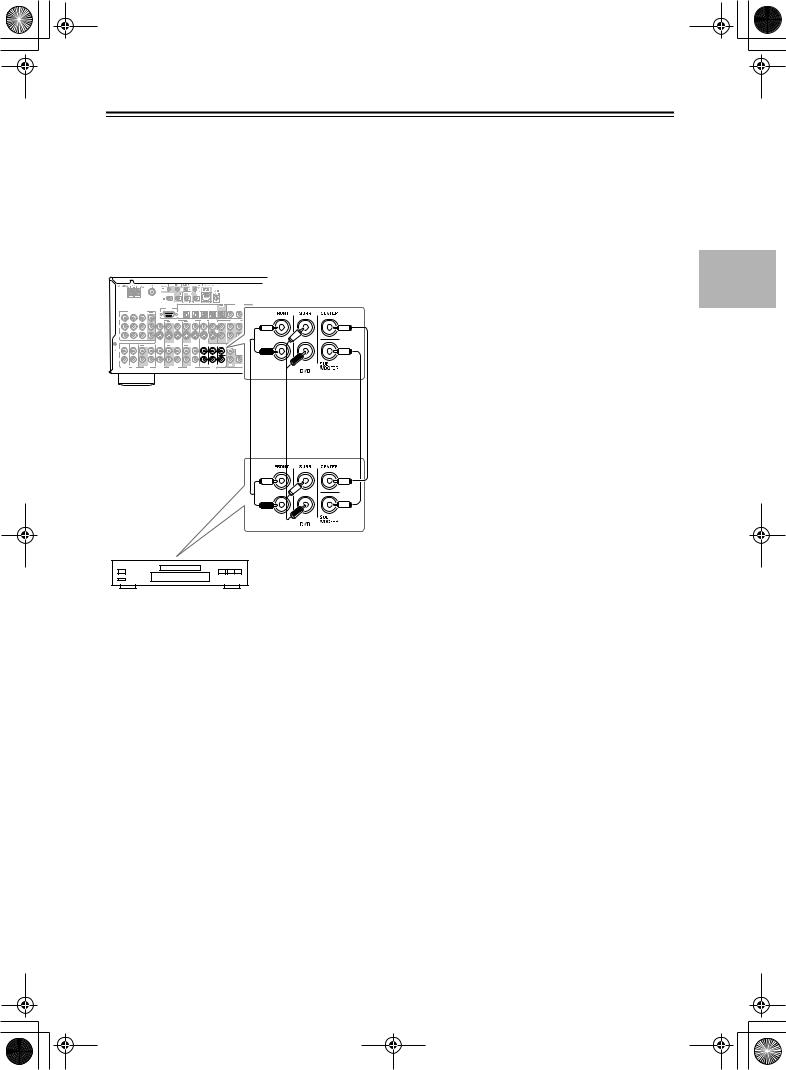
DTR-6.5,5.5_En.book Page 29 Wednesday, July 28, 2004 9:07 AM
Connecting the AV receiver—Continued
■ Using a Multichannel Connection
If your DVD player supports multichannel audio formats such as DVD-Audio, and it has a 5.1-channel analog audio output, you can enjoy DVD-Audio playback. Use a multichannel analog audio cable to connect the AV receiver’s DVD IN FRONT L/R, CENTER, SURR L/R, and SUBWOOFER jacks to the 5.1-channel analog audio output on your DVD player, as shown. Alternatively, use several analog audio cables.
|
|
|
|
IN4 |
IN3 |
IN2 |
IN1 |
OUT |
|
COMPONENT VIDEO |
RS232 |
OPTICAL |
|
|
|
|
|
|
OUT |
|
|
|
|
|
||
IN 3 |
IN 2 |
IN 1 |
|
|
|
|
|
|
Y |
|
|
|
|
|
|
|
|
VIDEO 3 |
VIDEO 2 |
|
VIDEO 1 |
|
DVD |
MONITOR |
IN |
OUT |
IN |
OUT |
IN |
IN |
OUT |
V
P
S
P
IN |
IN |
OUT |
IN |
IN |
OUT |
IN |
OUT |
IN |
FRONT |
SURR |
|
L |
|
|
|
|
|
|
|
|
|
|
|
GND |
|
|
|
|
|
|
|
|
|
|
|
R |
|
|
|
|
|
|
|
|
|
|
|
PHONO |
CD |
|
TAPE |
VIDEO 3 |
VIDEO 2 |
|
VIDEO 1 |
|
|
DVD |
W |
DVD player
29
 Loading...