


Camino ICP
Table of contents
 Loading...
Integra
®
Camino
®
ICP Monitor
USER’S MANUAL
Intracranial Pressure and Temperature Monitor

Publication Name
Integra Camino ICP Monitor User’s Manual
Integra Part Number 60903733 Rev. B
Effective Date September 2012
Tradema rk Acknowledgements
Integra, the Integra logo, and Camino are registered trademarks of Integra
LifeSciences Corporation or its subsidiaries in the United States and/or
other countries. Delta-Cal is a trademark of Utah Medical Products, Inc.
Sani-Cloth is a registered trademark of Professional Disposables
International, Inc. Aptimax, Sealsure, and Sterrad are registered trademarks
of Johnson and Johnson. Tyvec is a registered trademark of E.I. duPont.
Kimguard and One-Step are registered trademarks of Kimberly-Clark
Worldwide, Inc.
Copyright Information
©2012 Integra LifeSciences Corporation. All rights reserved.
No part of this document may be reproduced, stored in a retrieval system,
or transmitted, in any form or by any means—electronic, mechanical,
photocopying, recording, or otherwise—without the expressed, written
consent of Integra LifeSciences Corporation. Additional copies of this
document can be ordered from Integra LifeSciences Corporation.
Manufacturer:
Integra LifeSciences(Ireland) Limited
IDA Business and Technology Park
Sragh, Tullamore, County Offaly, Ireland
Distributed by:
Integra LifeSciences Corporation
311 Enterprise Drive
Plainsboro, NJ 08536 USA
Tel: 1-800-654-2873 (USA only)
1-(609) 275-0500
Fax: 1-609-275-5363
Internet Address: http://www.integralife.com
Made in Ireland. Printed in Ireland.
Caution
Federal (USA) law restricts this device to sale by or on the order of a
physician.
0086

This page is intentionally left blank.

i
TABLE OF CONTENTS
List of Symbols and Abbreviations
Packaging and Label Symbols................................................................................................................ v
Software Symbols .................................................................................................................................. vi
List of Abbreviations .............................................................................................................................. vii
Chapter 1: System Overview
Indications for Use / Intended Use ..........................................................................................................1
Contraindications ....................................................................................................................................1
Intended User..........................................................................................................................................1
Intended Patient Population ....................................................................................................................1
Description of the Integra Camino ICP Monitor.......................................................................................2
Key Functions of Monitor................................................................................................................2
Reviewing the User’s Manual..................................................................................................................2
List of Warnings for Using the Monitor ....................................................................................................3
Parts of the Monitor.................................................................................................................................6
About the Front Panel.....................................................................................................................6
About the Rear Panel .....................................................................................................................7
About the Right Panel.....................................................................................................................8
About the Bottom Panel..................................................................................................................9
About the Left Panel .......................................................................................................................9
Chapter 2: Setting Up System for the First Time
Procedures for Initial Setup ...................................................................................................................11
Chapter 3: Setting Up System for Clinical Use
Setting Up System for Clinical Use .......................................................................................................19
Positioning the Monitor .................................................................................................................19
Attaching to Equipment Pole (if applicable) ..................................................................................19
Powering the System On and Off .................................................................................................20
Using the Battery for Power..........................................................................................................21
Storing the Battery........................................................................................................................22
About the Integra Catheters ..................................................................................................................23
Connecting the Integra
®
Camino
®
Fiber Optic Catheters (110-4 Series) ..............................................24
Connecting the Integra
®
Camino
®
Flex Catheters .................................................................................27
Connecting to a Patient Bedside Monitor (if applicable) ......................................................................30

ii
Procedures for Synchronizing the Two Monitors ......................................................................... 30
About Pressure and Temperature Measurements on the Patient Bedside Monitor..................... 33
Storing the System ............................................................................................................................... 33
Chapter 4: Monitoring the Patient’s ICP and Temperature
About the Touch Screen....................................................................................................................... 35
About the Synchronize to Monitor Button .................................................................................... 36
Reviewing the Status Bar............................................................................................................. 36
Verifying Status of Battery and AC Power .................................................................................. 36
Verifying Amount of Battery Charge Available ............................................................................. 37
About the Alarms .................................................................................................................................. 37
Monitoring the Patient’s ICP and Temperature ....................................................................................37
Monitoring Trend Data.......................................................................................................................... 39
Conditions that Reset Trend Data................................................................................................40
Setting the High ICP Alarm Limit .......................................................................................................... 41
Specifying the High ICP Alarm Limit ............................................................................................ 42
Disabling the High ICP Alarm ...................................................................................................... 43
Silencing the High ICP Alarm Temporarily................................................................................... 43
Restoring Default High ICP Alarm Limit Values........................................................................... 43
Customizing the User Settings ............................................................................................................. 44
Chapter 5: Responding to Physiological and Technical Alarms
About the Two Alarm Types ................................................................................................................. 47
About the Technical Messages ............................................................................................................ 47
Understanding the Alarm Symbols ....................................................................................................... 48
How the Monitor Prioritizes the Alarms ............................................................................................... 48
Audio and Visual Indicators for Medium and Low Priority Alarms ............................................... 49
Priorities of Physiological and Technical Alarms ......................................................................... 49
List of Priorities for Each Alarm.................................................................................................... 50
Responding to the Physiological Alarm (ICP above alarm limit) .......................................................... 51
Responding to Technical Alarms .......................................................................................................... 51
Responding to Irreversible System Failure Alarms ...................................................................... 51
Responding to ICP Catheter Failure Alarm.................................................................................. 52
Responding to Temperature Sensor Failure Alarm ..................................................................... 52
Responding to Low Battery Alarm ............................................................................................... 52
Responding to Monitor Overheating Alarm.................................................................................. 53
Responding to Cooling Fan Failure Alarm ................................................................................... 53
Responding to Accuracy Range Alarm ........................................................................................ 54
Responding to Battery Failure Alarm ........................................................................................... 55

iii
Chapter 6: Extracting Trend Data for Remote Evaluation
About Data Extraction ...........................................................................................................................57
Extracting Data to USB Drive ...............................................................................................................57
How the Monitor Stores Trend Data for Up to 5 Days ..................................................................58
Extract Data via Digital Streaming ........................................................................................................59
Conditions That Reset Trend Data During Recording...........................................................................59
Chapter 7: Cleaning and Sterilizing the System
Cleaning the System and Components.................................................................................................61
Cleaning Guidelines .....................................................................................................................61
Sterilizing the Integra
®
Camino
®
Fiber Optic Catheter Cable ................................................................63
Sterilizing the Integra
®
Camino
®
Flex Extension Cable .........................................................................65
Sterilization Parameters ...............................................................................................................65
About Single-Use Only Catheters .........................................................................................................66
Disposal of the Monitor System and Components ................................................................................66
Chapter 8: Troubleshooting the System
About the Troubleshooting Process ......................................................................................................67
Responding to System Status Messages .............................................................................................67
Responding to Problems During Use ....................................................................................................69
Responding to System Failure Messages.............................................................................................73
Chapter 9: Testing and Preventive Maintenance
About These Procedures ......................................................................................................................75
Use Fiber Optic Catheters for Each Test......................................................................................75
Testing Pressure Input ..........................................................................................................................76
Using a Graduated Drainage Bag ................................................................................................76
Using a Pressure Simulator (preferred method) ...........................................................................78
Testing Pressure Output .......................................................................................................................79
Testing Temperature Input....................................................................................................................80
Testing Temperature Output .................................................................................................................81
Testing High ICP Alarm Limit ................................................................................................................84
Testing AC Power and Battery Charge .................................................................................................85
AC Power .....................................................................................................................................85
Low Battery Alarm ........................................................................................................................85
Battery Charge .............................................................................................................................86
Inserting A New Battery ........................................................................................................................86
Determining Software Version ..............................................................................................................87

iv
Testing Synchronizing to Patient Bedside Monitor ............................................................................... 87
Chapter 10: Contacting Integra for Technical Support and Annual Maintenance
About Technical Support ...................................................................................................................... 89
About Annual Maintenance .................................................................................................................. 89
Appendix A: Technical Specifications
List of Technical Specifications ............................................................................................................ 91
Classifications and Standards ............................................................................................................. 93
Manufacturer’s Declaration Table......................................................................................................... 94
General Notes.............................................................................................................................. 94
Appendix B: Integra Warranty
Warranty .............................................................................................................................................. 99
Index ..............................................................................................................................103
List of Symbols and Abbreviations • v
LIST OF SYMBOLS AND ABBREVIATIONS
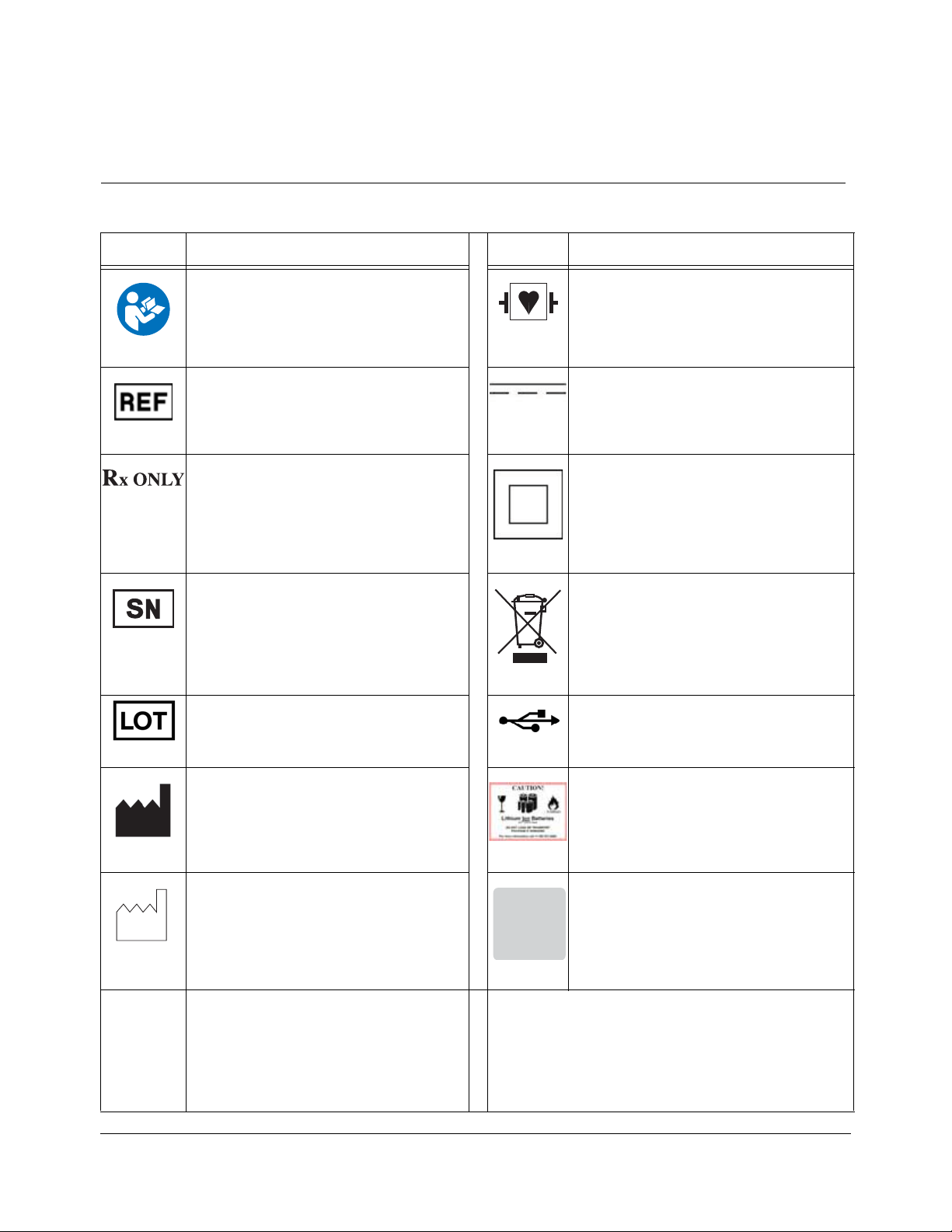
Packaging and Label Symbols
Symbol Definition Symbol Definition
Follow instructions for use Defibrillation-proof type CF applied part
Catalogue number Direct current
Caution: Federal (USA) law restricts this
device to sale by or on the order of a
physician.
Class II equipment
Serial number Waste Electronics and Electrical
Equipment
Batch code USB connection
Manufacturer Safety information for transporting
lithium ion batteries.
Date of manufacture Due date for annual maintenance
Temperature limitation
CALIBRATIONCALIBRATION
VERIFIED.VERIFIED.
NEXT SCHEDULEDNEXT SCHEDULED
MAINTENANCE DUEMAINTENANCE DUE
72903759 Rev 1
ll
-20°C
+50°C

vi • List of Symbols and Abbreviations
Software Symbols
Symbol Description Symbol Definition
Active alarm AC power not being used/available
Audio paused Battery charge indicator
Inactive alarm No battery connected or faulty battery
High ICP alarm limit Battery being charged
AC power being used System information panel
On/Off power

List of Symbols and Abbreviations • vii
List of Abbreviations
Abbreviation Definition
AC Alternating Current
º
CCelsius
CAMCABL Preamplification cable used with Integra fiber optic catheters
CSV Comma-separated values
CT Computer tomography
dB Decibels
DC Direct Current
DMM Digital Multimeter
EtO Ethylene oxide
º
F Fahrenheit
FLEX Flex Catheter
FLEXEXT Flex Extension Cable
hPA Hectopascal pressure unit
ICP Intracranial pressure
ICT Intracranial temperature
IPA Isopropyl alcohol
LED Light Emmitting Diode
mm Millimeters
mmHg Millimeters of mercury
MR Magnetic resonance
OR Operating Room
PMIO Patient Monitor Input Output
TBI Traumatic brain injury
USB Universal Serial Bus
VVolt
WWatt

viii • List of Symbols and Abbreviations
This page is intentionally left blank.

Chapter 1 • System Overview • 1
CHAPTER 1 SYSTEM OVERVIEW
Indications for Use / Intended Use................................................................. 1
Contraindications ............................................................................................ 1
Intended User................................................................................................... 1
Intended Patient Population ........................................................................... 1
Description of the Integra Camino ICP Monitor............................................ 2
Reviewing the User’s Manual ......................................................................... 2
List of Warnings for Using the Monitor ......................................................... 3
Parts of the Monitor......................................................................................... 6
Indications for Use / Intended Use
The Integra® Camino® ICP Monitor is indicated for use by qualified neurosurgeons
or neurointensivists for measurement of intracranial pressure and temperature.
Contraindications
The Integra Camino ICP Monitor and its accessories are contraindicated for use in
a Magnetic Resonance (MR) environment.
Intended User
The Integra Camino ICP Monitor is intended to be used by the following qualified
medical and biomedical professionals:
• A qualified neurosurgeon should perform the placement and handling of the
catheters.
• Designated qualified hospital staff (e.g. neurosurgeon, nurse, intensivist, trauma
physician, or physician’s assistant) should perform the operation of the monitor.
Chapter 9 provides instructions for testing and maintaining the monitor. The
procedures in this chapter are intended to be performed by the hospital’s
biomedical engineering staff.
Intended Patient Population
Patients undergoing treatment with this monitor under the cranial applications are
expected to have had a TBI, undergone a major neurosurgical procedure, or some
other traumatic, ischemic or hemorrhagic incident requiring controlled
monitoring of ICP and brain temperature.

2 • Chapter 1 • System Overview
Description of the Integra Camino ICP Monitor
The Integra Camino ICP Monitor is a compact, portable device that provides tools
for continuously determining and monitoring intracranial pressure (ICP) and
intracranial temperature (ICT) directly in the brain, depending on which catheters
are connected to the system. This monitor supports the following catheters:
• Series of Integra® Camino® Fiber Optic Catheters (110-4 series) for measuring both
ICP and temperature.
• Integra® Camino® Flex Catheter for measuring ICP values.
All Integra catheters measure their respective values at the tip of the catheter. This
design eliminates the need for a fluid-filled system to communicate pressure (and
carry pressure waves) to an external transducer.
Key Functions of Monitor
During clinical use, the Integra Camino ICP Monitor provides several key functions
to facilitate the process for monitoring and analyzing patient data:
• Touch screen interface for evaluating patient ICP/ICT data and setting patient
parameters (see
page 35)
• Physiological alarm that activates if the patient’s Mean ICP value exceeds a
user-specified limit for more than 5 seconds (see
page 41)
• Rechargeable lithium ion battery that supplies power to monitor during patient
transport (see
page 21)
• Storage of patient’s ICP trend data for up to 5 days (see page 39)
• Outputs for transferring patient data to a patient bedside monitor (see page 30)
• Outputs for extracting patient data to remote media types via USB drive or digital
streaming (see
page 57)
For instructions on using the Integra catheters, see the directions for use supplied
with each respective catheter.
Reviewing the User’s Manual
Integra recommends that all physicians, nurses, and technicians who will be using,
operating, and maintaining the Integra Camino ICP Monitor review this user’s
manual prior to using the system. If there are additional questions after reading
this manual, contact Integra.

Chapter 1 • System Overview • 3
List of Warnings for Using the Monitor
Failure to observe one or more of the following warnings could compromise
patient safety or result in measurement errors.
Warnings
• Use of the Integra Camino ICP Monitor is restricted to one patient at a time.
• The Integra Camino ICP Monitor and its accessories are contraindicated for use in a
Magnetic Resonance (MR) environment.
• Always verify the high ICP alarm limit is set appropriately for each patient prior to
treatment.
• Selecting the
Alarm Off feature on the Alarm panel will disable the high ICP alarm
limit indefinitely. Use caution if this feature is selected. To re-enable this alarm, press
the
Alarm On and Accept buttons.
• No modification of the Integra Camino ICP Monitor is allowed.
• The Integra Camino ICP Monitor is a sensitive electronic device. When using the
monitor, always handle with care. If damage is suspected, contact Integra.
• Read the user’s manual from the patient bedside monitor’s manufacturer before
connecting the Integra Camino ICP Monitor to a patient bedside monitor.
• To prevent injury to the patient, user, or other persons, or damage to the monitor,
always verify that the monitor is clamped securely to the equipment pole.
• To reduce the risk of electric shock, do not disassemble the Integra Camino ICP
Monitor. Refer all servicing to qualified service personnel at Integra.
• To prevent electrical shock, only use the AC power adapter supplied by Integra
(REF # MONPWR). Using a different AC power adapter may not provide protection
against electric shock.
• Danger - Possible explosion hazard if used in the presence of flammable anaesthetics.
• Only use Integra supplied accessories on the Integra Camino ICP Monitor. This applies
in particular to catheters, catheter cables, battery, AC power adapter, and
USB-to-R232 adapter cable.
• If the Integra Camino ICP Monitor loses power and shuts down while it is connected to
a patient bedside monitor, do not use the ICP values on the patient bedside monitor
for patient measurements; the ICP values on the patient bedside monitor will be
invalid.
• Connect the monitor to an AC power supply immediately if the low battery alarm is
activated.

4 • Chapter 1 • System Overview
• When using the battery:
- Do not heat above 80 °C.
- Do not open battery.
- Do not dispose of in fire.
- Do not short circuit as battery may ignite, explode, leak, or get hot causing
personal injury.
- Replace battery with same part number only (REF # BAT1001).
- Use of another battery may present a risk of fire or explosion.
• To prevent injury to the patient, user, or other persons, make sure that the battery
cover is closed securely during monitor use.
• Do not connect an Integra Camino Fiber Optic Catheter and an Integra Camino Flex
Catheter simultaneously to the monitor. The Integra Camino ICP Monitor is designed
to report ICP measurements with either the Flex Catheter or Fiber Optic Catheter
connected to the monitor, but not both together.
• To prevent possible patient injury resulting from incorrect ICP measurements, always
perform the steps listed on page 23 before implanting a new Integra Camino Fiber
Optic Catheter into the patient. In particular, always make sure to adjust the new Fiber
Optic Catheter’s ICP value to zero before implantation while the catheter is in the air.
Never attempt to re-zero a catheter while the catheter is inside the patient.
• Once the Integra Camino Fiber Optic Catheter has been zeroed to the Integra Camino
ICP Monitor, do not replace the Fiber Optic Catheter Cable being used for patient
measurement. Replacing the Fiber Optic Catheter Cable with another cable after the
catheter has already been zeroed may result in inaccurate patient measurements.
• Once the Integra Camino Fiber Optic Catheter has been zeroed to the Integra Camino
ICP Monitor, do not transfer this zeroed catheter to any other monitor. Transferring a
zeroed catheter to a different monitor may result in inaccurate ICP measurements.
• To prevent possible patient injury resulting from incorrect ICP measurements, always
perform each of the steps listed on page 26 before implanting a new Integra Camino
Flex Catheter into the patient. In particular, always leave the Flex Catheter in the air
until the monitor completes the autozero (i.e. initialization) process successfully.
• Once the Integra Camino Flex Catheter has been initialized (autozeroed) by the Integra
Camino ICP Monitor, do not replace the Integra Camino Flex Extension Cable being
used for patient measurement. Replacing the Flex Extension Cable with another cable
after the Flex Catheter has already been initialized may result in inaccurate ICP
measurements.
• Once the Integra Camino Flex Catheter has been initialized (i.e. autozeroed) by the
Integra Camino ICP Monitor, do not transfer this initialized catheter to any other
monitor. Transferring an initialized catheter to a different monitor may result in
inaccurate ICP measurements.
Warnings

Chapter 1 • System Overview • 5
• The Integra Camino ICP Monitor will only store the Mean ICP data from the most
recent 5 days. All stored trend data older than 5 days will be lost. If monitoring is
continued for more than 5 days, placement of a new catheter under sterile conditions
is recommended. Note that replacing a catheter will reset the trend data. Please
extract any data that you wish to retain prior to replacing the catheter.
• Do not autoclave or immerse the Integra Camino ICP Monitor in liquid as damage may
occur. If the monitor is exposed to liquids, turn off the unit, remove the AC power
adapter, dry the unit thoroughly, and send to biomed staff for evaluation before
reapplying power.
• Only use the cleaning agents listed in Chapter 7 for cleaning and disinfecting the
Integra Camino ICP Monitor system. Using solvents or cleaning agents not listed in
Chapter 7 may damage the plastic exterior of the Integra Camino ICP Monitor.
Warnings
6 • Chapter 1 • System Overview
Parts of the Monitor
The Integra Camino ICP Monitor contains hardware, software, and electrical
components that support specific Integra catheters for monitoring the patient’s
ICP and temperature. The following section provides information on the different
parts of the monitor.
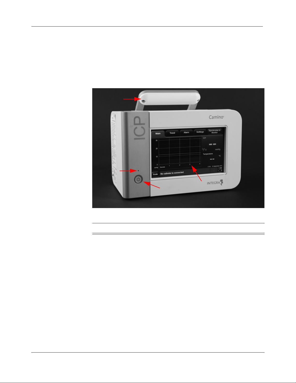
About the Front Panel
The front panel contains:
Number Item Description
1 Handle Handle used for carrying the monitor.
2 Power Status Green LED button that indicates the monitor is
being powered by the AC power adapter. Note
that this button does not illuminate if the monitor
is being powered by the battery.
3 Power Button Turns the monitor on and off. This button is
illuminated when the power is on.
4 Touch Screen Provides software tools for viewing data and
controlling parameters for monitoring the
patient’s ICP and ICT levels.
2
3
4
1

Chapter 1 • System Overview • 7
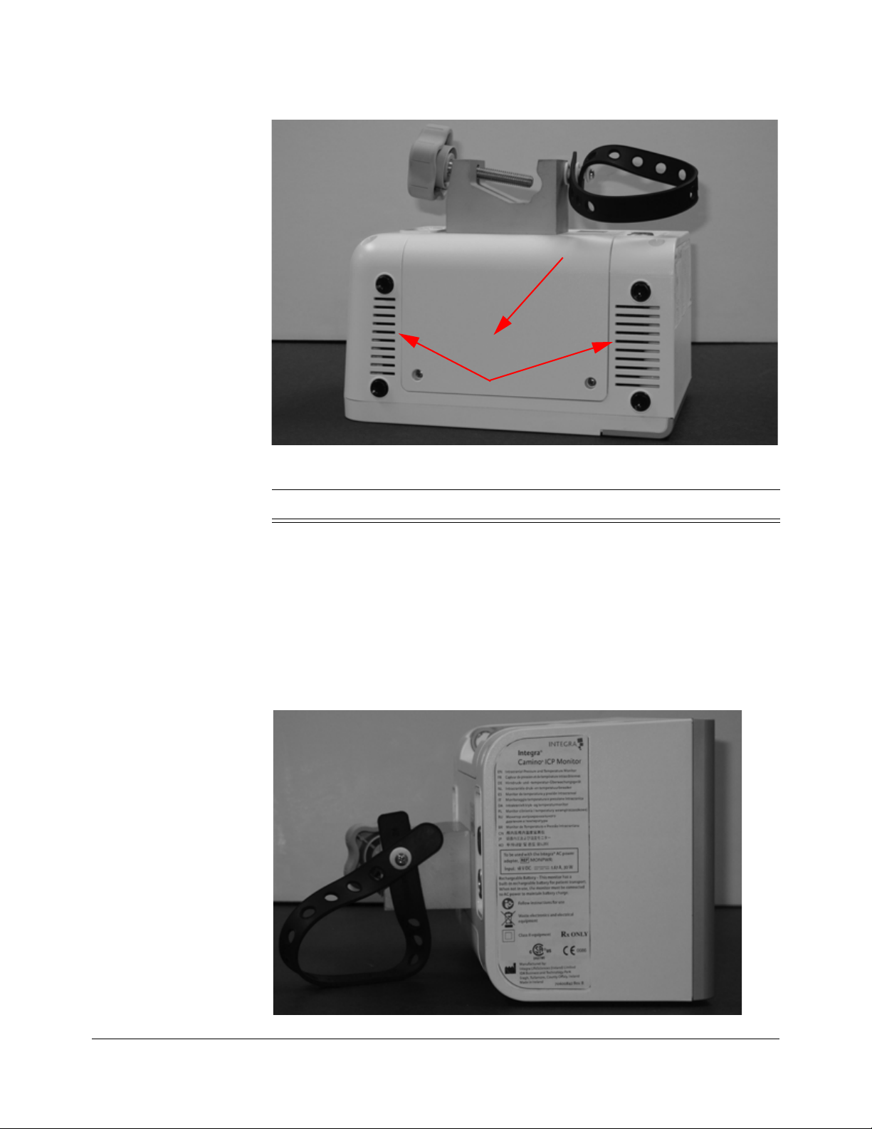
About the Rear Panel
The rear panel contains:
Number Item Description
1 USB Port Connection port for extracting trend data via
USB transfer or digital streaming.
2 AC Power Adapter Port Connection port for the AC power cord.
3 PMIO Port Connection port for PMIO cable. This cable
is used to connect the Integra Camino ICP
Monitor to a patient bedside monitor.
4 Pole Clamp Clamping system for securing monitor to an
equipment pole.
5 Air Vent Grated opening that allows air being
circulated by the internal cooling fan to leave
the monitor.
6 Cable Strap Rubber strap used to secure AC power
adapter during transport.
1
2
5
6
4
3

8 • Chapter 1 • System Overview
About the Right Panel
The right panel contains:
Number Item Description
1 Temperature Port Connection port for the temperature connector on
the Fiber Optic Catheter Cable.
2 Pressure Port Connection port for the ICP connector on the
Integra Camino Flex Extension Cable (pressure
only).
3 Pressure Port Connection port for the ICP connector on the
Fiber Optic Catheter Cable.
1
2
3
Chapter 1 • System Overview • 9
About the Bottom Panel
The bottom panel contains:
About the Left Panel
The left panel does not contain any usable connector ports or buttons.
Number Item Description
1 Battery Door Cover Removable cover for accessing/replacing the
14.4V lithium ion battery.
2 Air Vent Grated opening that allows air being circulated
by the internal cooling fan to leave the monitor.
1
2

10 • Chapter 1 • System Overview
This page is intentionally left blank.

Chapter 2 • Setting Up System for the First Time • 11
CHAPTER 2 SETTING UP SYSTEM FOR THE FIRST TIME
Procedures for Initial Setup
Step 1: Unpack the System (REF # CAM02)
Remove the contents from the Integra® Camino® ICP Monitor shipping box and
verify the following items are included.
Warning
Only use Integra supplied accessories on the Integra Camino ICP
Monitor. This applies in particular to catheters, catheter cables, battery,
AC power adapter, and USB-to-R232 adapter cable.
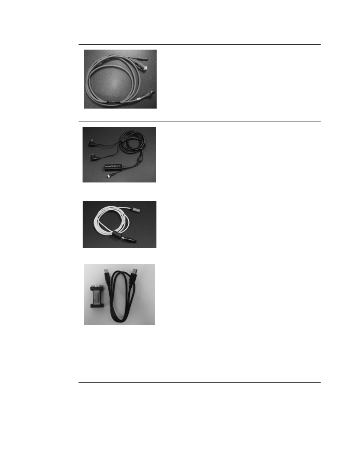
Content Description
• Integra Camino ICP Monitor
•Quantity = 1
• AC power adapter (18 V DC , 1.67 A, 30 W)
•REF # MONPWR
•Quantity = 1
• 14.4 V lithium ion battery
•REF # BAT1001
•Quantity = 1
12 • Chapter 2 • Setting Up System for the First Time
After unpacking the contents, inspect the shipment for any signs of damage or
loss. If any damages are discovered, notify the carrier, the supplier, and retain all
shipping cartons for examination.
• Integra® PMIO patient bedside monitor cable
• REF # PMIOMPM
•Quantity = 1
• Integra® Camino® Fiber Optic Catheter Cable
• REF # CAMCABL
•Quantity = 1
• Integra® Camino® Flex Extension Cable
• REF # FLEXEXT
•Quantity = 1
• USB-to-RS232 adapter cable
• REF # EXPORTCAB
•Quantity = 1
•User manual
• REF # UM-CAM02
XX
(where
XX refers to the country’s language code)
•Quantity = 1
Content Description

Chapter 2 • Setting Up System for the First Time • 13
Step 2: Install the Battery
Perform the following steps with a Phillips screwdriver and the Integra-supplied
14.4 V lithium ion battery.
1. Make sure the monitor is unplugged and turned off.
2. Turn the monitor upside down so the handle is facing downward.
3. Remove the 2 screws to take off the battery cover.
4. Verify the Integra logo on the battery is facing up and insert the battery:
A. Align the battery’s connectors on the front of the battery to the connector
slots on the monitor.
B. Slide the battery’s connector into the monitor’s connector slots until the
battery is fully inserted into place.
5. Secure the battery cover to the monitor by re-inserting the two small screws.
14 • Chapter 2 • Setting Up System for the First Time
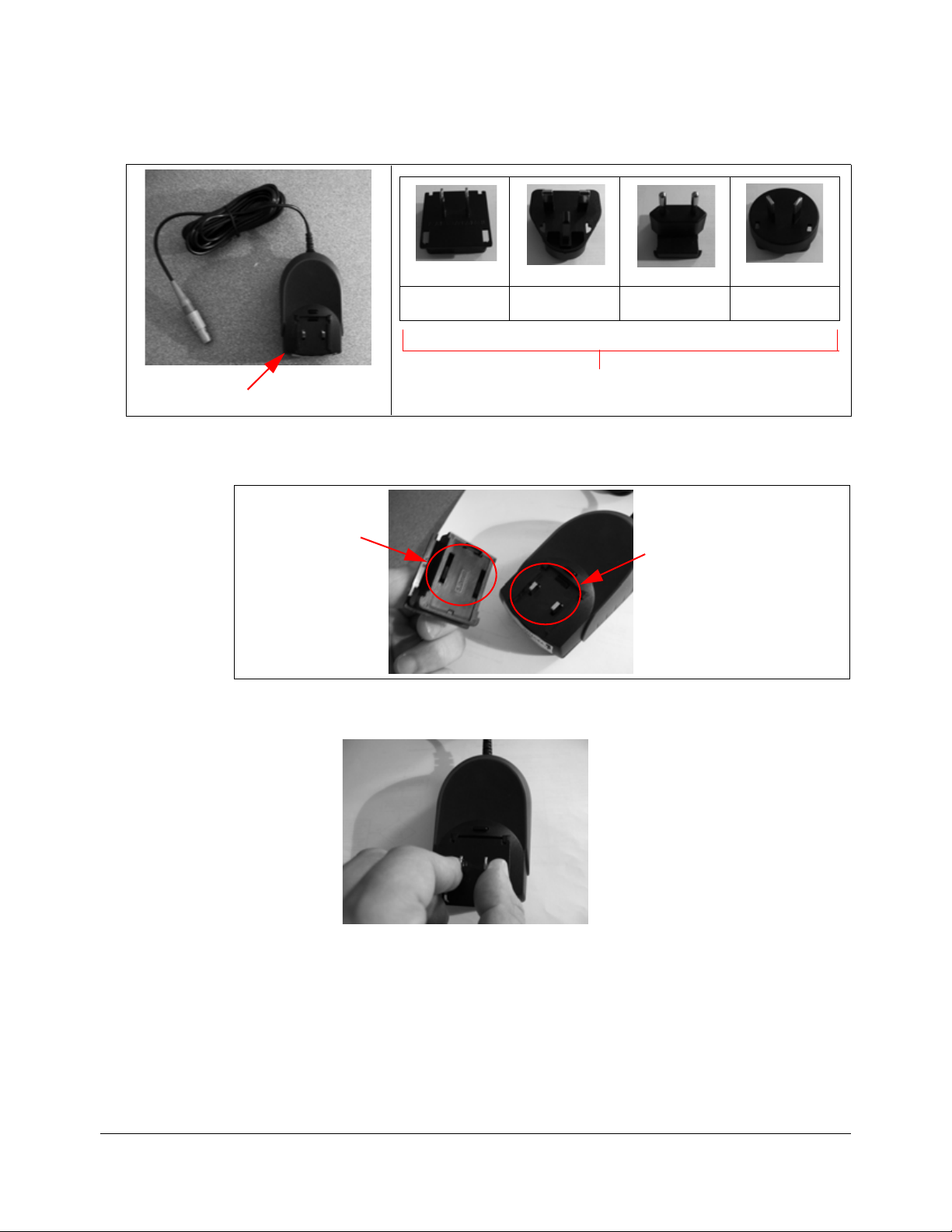
Step 3: Prepare the AC Power Adapter with Region-Specific Plug
1. Remove the AC power adapter from the package and attach the region-specific
adapter plug to the backside of the AC power adapter.
A. Align the two slots on the adapter plug over the two prongs on the AC
power adapter.
B. Push the adapter plug down over the two prongs until the entire base of
the plug sits flush against the AC power adapter.
Backside of AC power adapter
US UK Europe Australia
Region-Specific Adapter Plugs
Prongs on AC power adapter
Slots on
adapter plug
Chapter 2 • Setting Up System for the First Time • 15
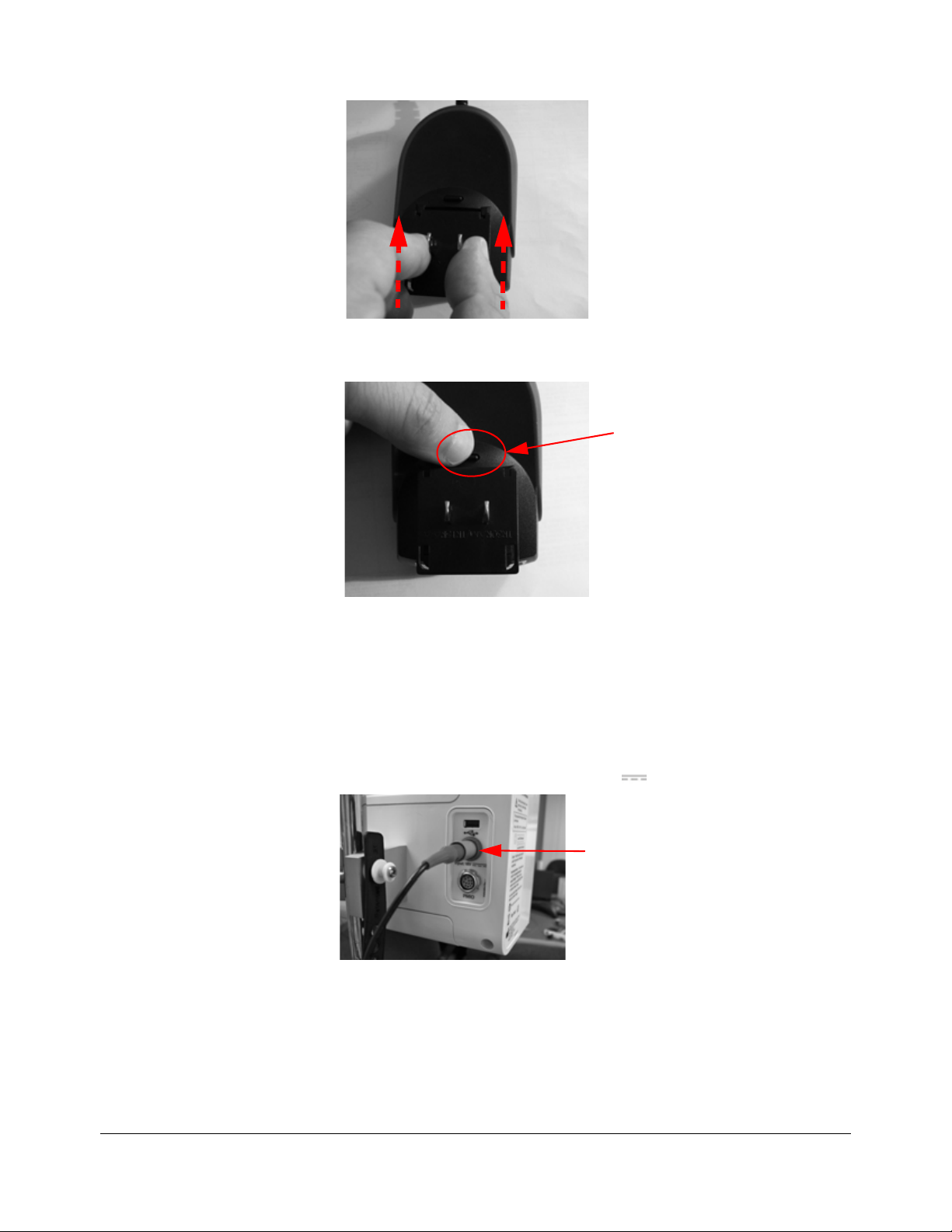
C. Gently slide the adapter plug forward until it snaps into place.
2. To remove the adapter plug, press the release button on the AC power adapter
and pull the plug away from the adapter.
Step 4: Plug the Monitor into AC Power
Perform the following steps with the Integra-supplied AC power adapter:
1. Place the monitor on a flat surface.
2. Connect the AC power adapter to the Integra Camino ICP Monitor:
A. On the back of the monitor, attach the connector end of the AC power
adapter into the port labeled
Input: 18 V .
B. Insert the plug end of the AC power adapter into a grounded AC wall
outlet.
3. Turn on the monitor. On the front of the monitor, press the power button; the
Integra Camino ICP Monitor will display the Integra logo before initiating the
monitor setup process.
Press the release button to
remove adapter plug
Connector end of
AC power adapter

16 • Chapter 2 • Setting Up System for the First Time
4. After the initial setup process completes, the Integra Camino ICP Monitor
sounds a one-second startup tone and displays the
Main panel on the touch
screen.
Step 5: Set the Time and Date
1. On the touch screen, press the Settings tab and select Set Time and Date.
2. On the displayed panel, press the desired field (hour, minutes, date, month, or
year) and use the arrows to specify the appropriate setting. Note that you may
adjust each of these settings prior to accepting them in the following step.
3. Press Accept; the Integra Camino ICP Monitor will display the selected time/date
on the touch screen.
Step 6: Specify the Language
1. On the touch screen, press the
Settings tab (fourth tab from the left)
2. Press Set Language.
Caution
The purpose of the startup tone verifies that the audio alarms are
functioning correctly. If this tone does not sound during the startup
process, contact Integra for service.
Settings tab
Set Language
button

Chapter 2 • Setting Up System for the First Time • 17
3. In the displayed Language: menu,
use the arrows to select the desired
language.
4. Press Accept; the Integra Camino ICP Monitor will display all of the text that
appears on the touch screen in the selected language.
Step 7: Use AC Power to Charge the Battery to Full Capacity
1. Turn off the monitor. On the front of the monitor, press the power button.
2. Keep the Integra Camino ICP Monitor on AC power with the monitor turned off
for 5 hours. This will re-charge the battery to full capacity.
3. After 5 hours, turn on the monitor by pressing the power button.
4. On the touch screen, view the battery power symbol on the status
bar to verify the symbol displays four green bars; this indicates the
battery has full charge.

18 • Chapter 2 • Setting Up System for the First Time
This page is intentionally left blank.

Chapter 3 • Setting Up System for Clinical Use • 19
CHAPTER 3 SETTING UP SYSTEM FOR CLINICAL USE
Setting Up System for Clinical Use.............................................................. 19
About the Integra Catheters ......................................................................... 23
Connecting the Integra® Camino® Fiber Optic Catheters (110-4 Series) 24
Connecting the Integra® Camino® Flex Catheters .................................... 27
Connecting to a Patient Bedside Monitor (if applicable) ........................... 30
Storing the System........................................................................................ 33
Setting Up System for Clinical Use
The following section contains instructions for positioning the monitor, powering
the monitor, and connecting catheters to the monitor prior to clinical use.
Positioning the Monitor
The Integra® Camino® ICP Monitor is intended to be positioned on a hard flat
surface or securely clamped to an equipment pole or bed support next to the
patient. The distance between the patient and the monitor is restricted by the
length of the Integra catheter cable. It is not permitted to extend the Integra
catheter cable with non-Integra extension cables.
Attaching to Equipment Pole (if applicable)
The Integra Camino ICP Monitor includes a clamp for attaching the monitor to an
equipment pole. To attach:
1. On the rear of the monitor, fit the pole clamp around the equipment pole.
Caution
To prevent the monitor from overheating:
• Do not block the air vents on the rear and bottom of the unit
• Do not place the monitor on a soft or uneven surface, which may result in
blockage of the monitor’s air vents. For example, do not place the monitor
on the bed during patient transport.
Loading...