


AV Receiver
DTR-10.5
Instruction Manual
WARNING:
TO REDUCE THE RISK OF FIRE OR ELECTRIC SHOCK, DO NOT EXPOSE THIS APPARATUS TO RAIN OR MOISTURE.
CAUTION:
TO REDUCE THE RISK OF ELECTRIC SHOCK, DO NOT REMOVE COVER (OR BACK). NO USER-SERVICEABLE PARTS INSIDE. REFER SERVICING TO QUALIFIED SERVICE PERSONNEL.
WARNING |
|
AVIS |
RISK OF ELECTRIC SHOCK |
|
RISQUE DE CHOC ELECTRIQUE |
DO NOT OPEN |
|
NE PAS OUVRIR |
The lightning flash with arrowhead symbol, within an equilateral triangle, is intended to alert the user to the presence of uninsulated “dangerous voltage” within the product’s enclosure that may be of sufficient
magnitude to constitute a risk of electric shock to persons.
The exclamation point within an equilateral triangle is intended to alert the user to the presence of important operating and maintenance (servicing) instructions in the literature accompanying the appliance.
Important Safety Instructions
1.Read these instructions.
2.Keep these instructions.
3.Heed all warnings.
4.Follow all instructions.
5.Do not use this apparatus near water.
6.Clean only with dry cloth.
7.Do not block any ventilation openings. Install in accordance with the manufacturer’s instructions.
8.Do not install near any heat sources such as radiators, heat registers, stoves, or other apparatus (including amplifiers) that produce heat.
9.Do not defeat the safety purpose of the polarized or grounding-type plug. A polarized plug has two blades with one wider than the other. A grounding type plug has two blades and a third grounding prong. The wide blade or the third prong are provided for your safety. If the provided plug does not fit into your outlet, consult an electrician for replacement of the obsolete outlet.
10.Protect the power cord from being walked on or pinched particularly at plugs, convenience receptacles, and the point where they exit from the apparatus.
11.Only use attachments/accessories specified by the manufacturer.
12.Use only with the cart, stand, tripod, bracket, or table specified by the manufacturer, or sold with the apparatus. When a cart is used, use caution when moving the cart/ apparatus combination to avoid injury from tip-over.
PORTABLE CART WARNING
S3125A 
13.Unplug this apparatus during lightning storms or when unused for long periods of time.
14.Refer all servicing to qualified service personnel. Servicing is required when the apparatus has been damaged in any way, such as power-supply cord or plug is damaged, liquid has been spilled or objects have fallen into the apparatus, the apparatus has been exposed to rain or moisture, does not operate normally, or has been dropped.
15.Damage Requiring Service
Unplug the apparatus from the wall outlet and refer servicing to qualified service personnel under the following conditions:
A.When the power-supply cord or plug is damaged,
B.If liquid has been spilled, or objects have fallen into the apparatus,
C.If the apparatus has been exposed to rain or water,
D.If the apparatus does not operate normally by following the operating instructions. Adjust only those controls that are covered by the operating instructions as an improper adjustment of other controls may result in damage and will often require extensive work by a qualified technician to restore the apparatus to its normal operation,
E.If the apparatus has been dropped or damaged in any way, and
F.When the apparatus exhibits a distinct change in performance this indicates a need for service.
16.Object and Liquid Entry
Never push objects of any kind into the apparatus through openings as they may touch dangerous voltage points or short-out parts that could result in a fire or electric shock.
The apparatus shall not be exposed to dripping or splashing and no objects filled with liquids, such as vases shall be placed on the apparatus.
Don’t put candles or other burning objects on top of this unit.
17.Batteries
Always consider the environmental issues and follow local regulations when disposing of batteries.
18.If you install the apparatus in a built-in installation, such as a bookcase or rack, ensure that there is adequate ventilation.
Leave 20 cm (8") of free space at the top and sides and 10 cm (4") at the rear. The rear edge of the shelf or board above the apparatus shall be set 10 cm (4") away from the rear panel or wall, creating a flue-like gap for warm air to escape.
2

Thank you for purchasing an Integra AV Receiver.
Please read this manual thoroughly before making connections and plugging in the unit. Following the instructions in this manual will enable you to obtain optimum performance and listening enjoyment from your new AV Receiver.
Please retain this manual for future reference.
Precautions
1.Recording Copyright
Unless it’s for personal use only, recording copyrighted material is illegal without permission of the copyright holder.
2.AC Fuse
The AC fuse inside the DTR-10.5 is not user-serviceable. If you cannot turn on the DTR-10.5, contact your Integra dealer.
3.Care
Occasionally you should dust the DTR-10.5 all over with a soft cloth. For stubborn stains, use a soft cloth dampened with a weak solution of mild detergent and water. Dry the DTR-10.5 immediately afterwards with a clean cloth. Don’t use abrasive cloths, thinners, alcohol, or other chemical solvents, because they may damage the finish or remove the panel lettering.
4.Power
WARNING
BEFORE PLUGGING IN THE UNIT FOR THE FIRST TIME, READ THE FOLLOWING SECTION CAREFULLY. AC outlet voltages vary from country to country. Make sure that the voltage in your area meets the voltage requirements printed on the DTR-10.5’s rear panel (e.g., AC 230 V, 50 Hz or AC 120 V, 60 Hz).
Setting the [Standby/On] switch to Standby does not fully shutdown the DTR-10.5. If you do not intend to use the DTR-10.5 for an extended period, remove the power cord from the AC outlet.
For U.S. Models
Note to CATV system installer:
This reminder is provided to call the CATV system installer’s attention to Section 820-40 of the NEC which provides guidelines for proper grounding and, in particular, specifies that the cable ground shall be connected to the grounding system of the building, as close to the point of cable entry as practical.
FCC Information for User
CAUTION:
The user changes or modifications not expressly approved by the party responsible for compliance could void the user’s authority to operate the equipment.
NOTE:
This equipment has been tested and found to comply with the limits for a Class B digital device, pursuant to Part 15 of the FCC Rules. These limits are designed to provide reasonable protection against harmful interference in a residential installation.
This equipment generates, uses and can radiate radio frequency energy and, if not installed and used in accordance with the instructions, may cause harmful interference to radio communications. However, there is no guarantee that interference will not occur in a particular installation. If this equipment does cause harmful interference to radio or television reception, which can be determined by turning the equipment off and on, the user is encouraged to try to correct the interference by one or more of the following measures:
•Reorient or relocate the receiving antenna.
•Increase the separation between the equipment and receiver.
•Connect the equipment into an outlet on a circuit different from that to which the receiver is connected.
•Consult the dealer or an experienced radio/TV technician for help.
For Canadian Models
NOTE:
THIS CLASS B DIGITAL APPARATUS COMPLIES WITH CANADIAN ICES-003.
RSS 210, Low Power Licence-Exempt Radiocommunications Devices (All FrequencyBands).
For models having a power cord with a polarized plug:
CAUTION:
TO PREVENT ELECTRIC SHOCK, MATCH WIDE BLADE OF PLUG TO WIDE SLOT, FULLY INSERT.
Modèle Canadien
REMARQUE:
CET APPAREIL NUMÉRIQUE DE LA CLASSE B EST CONFORME À LA NORME NMB-003 DU CANADA. CNR-210, Dispositifs de radiocommunications de faible puissance, exempts de licence (pour toutes les bandes de fréquences).
Sur les modèles dont la fiche est polarisée:
ATTENTION:
POUR ÉVITER LES CHOCS ÉLECTRIQUES, INTRODUIRE LA LAME LA PLUS LARGE DE LA FICHE DANS LA BORNE CORRESPONDANTE DE LA PRISE ET POUSSER JUSQU’AU FOND.
Getting Started
3
Table of Contents
Getting Started |
|
Important Safety Instructions .......................... |
2 |
Precautions........................................................ |
3 |
Features ............................................................. |
6 |
Supplied Accessories ....................................... |
8 |
Connecting the Supplied Power Cord ............ |
8 |
Before Using the DTR-10.5 ............................... |
9 |
Installing the Batteries .................................... |
9 |
Using the Remote Controller .......................... |
9 |
Types of the DTR-10.5 Option Boards ......... |
10 |
Installing the Option Boards |
|
(USA and Australian Models Only) ............ |
11 |
Index Parts and Facilities ............................... |
12 |
Front Panel ................................................... |
12 |
Front Panel Display ...................................... |
15 |
Rear Panel.................................................... |
16 |
Remote Controller (Amp Mode).................... |
18 |
Installation and Connections |
|
Speaker Placement ......................................... |
20 |
Basic Speaker Placements for Home Theater |
|
and the Function of Respective Speakers ... |
20 |
Placing the Speakers.................................... |
21 |
Speaker Placement Suitable for THX Audio ... |
22 |
Speaker Placement Suitable for a Music |
|
Source such as DVD-Audio ....................... |
22 |
Available Speaker Placements According to |
|
the Number of Speakers ............................ |
23 |
Connection Examples................................... |
24 |
Connecting Speakers...................................... |
27 |
Connecting to the Speaker Terminals .......... |
27 |
Connecting a Subwoofer .............................. |
28 |
Connecting Auxiliary Power Amplifier |
|
(For Speaker System [A] only) ................... |
28 |
Using the BTL Connection............................ |
29 |
Using Bi-amp Connection............................. |
29 |
Connecting Antennas ..................................... |
30 |
Connecting the Indoor FM Antenna.............. |
30 |
Connecting the AM Loop Antenna................ |
31 |
Connecting an Outdoor FM Antenna............ |
31 |
Connecting an Outdoor AM Antenna............ |
31 |
Connecting AV Components.......................... |
32 |
Types of Connection Cables and Terminals ... |
32 |
Connecting Monitors such as TV or |
|
Projector..................................................... |
34 |
Connecting a DVD Player............................. |
35 |
Connecting a DVD Recorder or Digital VCR |
|
(VIDEO 1)................................................... |
36 |
Connecting a VCR (VIDEO 2, VIDEO 3) ...... |
37 |
Connecting a DBS Tuner, DBS TV, or BS/CS |
|
Tuner.......................................................... |
39 |
Connecting a Portable DVD Player or Video |
|
Camcorder ................................................. |
40 |
Connecting a CD Player, Turntable or |
|
Tuner.......................................................... |
40 |
Connecting a Recording Device such as MD |
|
Recorder, DAT Deck, CD Recorder or |
|
Cassette Deck............................................ |
41 |
Connection Using the i.LINK (AUDIO) |
|
Terminal ( )............................................. |
42 |
Connection Using HDMI Terminals............... |
45 |
|
Connecting |
- compatible AV |
|
Components |
................................................ |
47 |
Connections for Remote Control ( ).......... |
47 |
|
Connecting Components not Reached by the |
||
Remote Controller .............Signals (IR IN) |
48 |
|
If Remote Controller Signal Does not Reach |
|
|
the DTR-10.5 ....................Remote Sensor |
48 |
|
Using an External Device with 12V Trigger |
|
|
Terminal ....................................................... |
|
49 |
Operations |
|
|
Basic Operation of Remote Controller |
|
|
Buttons ........................................................ |
|
50 |
To Operate the ........DTR-10.5 (AMP Mode) |
50 |
|
To Select an Input .............................Source |
50 |
|
To Operate a Connected Component (Mode |
|
|
Switching) ................................................... |
|
51 |
To Select a Source .......in Zone 2 or Zone 3 |
51 |
|
To Perform a .....................Macro Operation |
51 |
|
Customizing Your ............Remote Controller |
51 |
|
Connecting the .....Power/Basic Operations |
52 |
|
Turning on the ....................................Power |
52 |
|
Operating on the ...........................DTR-10.5 |
52 |
|
Turning on the Power from the Remote |
|
|
Controller .................................................... |
|
53 |
Operating with .................Remote Controller |
53 |
|
Using the Listening ............................Modes |
58 |
|
Selecting the Listening ........................Mode |
61 |
|
Listening to Radio ......................Broadcasts |
62 |
|
Using the Tuner............................................. |
62 |
|
Tuning into a Radio ...........................Station |
62 |
|
Enjoying Multichannel ...................Playback |
64 |
|
How to Connect............................................. |
64 |
|
How to Set Up ............................................... |
64 |
|
Playing Back in .............Multichannel Sound |
65 |
|
Adjusting the Volume Level of Speakers for |
|
|
Multichannel ................................Playback |
65 |
|
Enjoying Movies and Music in the Remote |
|
|
Zone (Zone 2/3) ........................................... |
66 |
|
Connecting and ...................................Setup |
66 |
|
Enjoying Movies and Music in a Remote |
|
|
Zone ........................................................... |
|
67 |
Recording a Source........................................ |
69 |
|
Recording Audio/Video ...........While Playing |
70 |
|
Recording Audio/Video on a Component |
|
|
While Playing ................................Another |
70 |
|
Recording the Video from One Source and |
|
|
the Audio from ..................Another Source |
71 |
|
Enjoying Net Audio......................................... |
72 |
|
About Net-Tune............................................. |
72 |
|
Networking Your ...........................DTR-10.5 |
73 |
|
Using the Remote .........................Controller |
74 |
|
Enjoying Internet .................................Radio |
76 |
|
Playing a Music File Saved on the Network |
|
|
Audio Server............................................... |
78 |
|
Configuring the ........................Music Server |
80 |
|
4
Table of Contents—Continued
Setup Menu |
|
Setup Menu...................................................... |
82 |
OSD Map (MAIN A)....................................... |
82 |
OSD Map (MAIN B)....................................... |
84 |
OSD Map (ZONE 2) ...................................... |
85 |
Navigating the Setup Menu........................... |
86 |
Hardware Setup............................................... |
87 |
Remote Control Setup Sub-menu ................. |
87 |
TV Format Sub-menu.................................... |
87 |
AM Frequency Setup Sub-menu |
|
(Australian Models Only) ............................ |
87 |
Speaker/Output Setup .................................... |
88 |
Speaker Configuration Sub-menu................. |
88 |
Speaker Impedance Sub-menu .................... |
89 |
Speaker Crossover Sub-menu...................... |
89 |
Speaker Distance Sub-menu ........................ |
89 |
Notch Filter Sub-menu .................................. |
90 |
Level Calibration Sub-menu.......................... |
90 |
THX Audio Setup Sub-menu......................... |
91 |
Audio Output Assign Sub-menu.................... |
91 |
Video Output Assign Sub-menu.................... |
92 |
Input Setup ...................................................... |
93 |
Audio Assign Sub-menu (when input is |
|
other than NET AUDIO).............................. |
94 |
Music Server Sub-menu (when input is NET |
|
AUDIO) ....................................................... |
95 |
Video Assign Sub-menu................................ |
95 |
Listening Mode Preset Sub-menu................. |
96 |
Character Edit Sub-menu.............................. |
97 |
IntelliVolume Sub-menu ................................ |
98 |
Delay Sub-menu ........................................... |
98 |
12V Trigger Assign Sub-menu ...................... |
98 |
Listening Mode Setup..................................... |
99 |
Mono Setup Sub-menu ................................. |
99 |
Multiplex Setup Sub-menu ............................ |
99 |
Stereo Setup Sub-menu.............................. |
100 |
Direct, Pure Audio Setup Sub-menu ........... |
101 |
Multichannel Input Setup Sub-menu ........... |
102 |
i.LINK(IEEE1394):DVD-Audio Input Setup |
|
Sub-menu ................................................. |
103 |
i.LINK(IEEE1394):SACD Input Setup |
|
Sub-menu ................................................. |
105 |
Dolby Digital Setup Sub-menu .................... |
106 |
DTS Setup Sub-menu ................................. |
108 |
AAC Setup Sub-menu................................. |
109 |
Dolby Pro Logic IIx/DTS NEO:6 |
|
(2ch Input only) Setup Sub-menu............. |
110 |
THX Setup Sub-menu ................................. |
112 |
Mono Movie Setup/Enhance Setup/Orchestra |
|
Setup/Unplugged Setup/Studio-Mix Setup/ |
|
TV Logic Setup Sub-menu ....................... |
114 |
All Ch Stereo Setup/Full Mono Setup |
|
Sub-menu ................................................. |
115 |
Dolby Virtual Speaker Setup Sub-menu ..... |
116 |
Dolby Headphone Setup Sub-menu ........... |
117 |
Audio Adjust.................................................. |
118 |
Tone Control Sub-menu.............................. |
118 |
Preferences ................................................... |
119 |
Volume Setup Sub-menu ............................ |
119 |
Headphone Level Setup Sub-menu ............ |
119 |
OSD Setup Sub-menu ................................ |
119 |
OSD Position Sub-menu ............................. |
119 |
i.LINK Setup ................................................... |
120 |
|
Wakeup Setup ............................................ |
120 |
|
OSD for DVD .............................................. |
120 |
|
OSD for DVD (Zone 2) ............................... |
120 |
|
DVD Output Synchro .................................. |
120 |
|
Network Setup ............................................... |
121 |
|
IP Address Sub-menu ............................... |
121 |
|
Proxy Sub-menu........................................ |
121 |
|
MAC Address Sub-menu............................ |
121 |
|
Client Sub-menu......................................... |
122 |
|
Lock/Version Setup....................................... |
123 |
|
Lock Setup Sub-menu ................................ |
123 |
|
Firmware Version Sub-menu...................... |
123 |
|
Using the Remote Controller |
|
|
Operating Integra/Onkyo Products Using the |
||
Remote Controller ..................................... |
124 |
|
Operating Integra/Onkyo Products Using |
|
|
the |
Connection .................................. |
124 |
DVD Mode .................................................. |
124 |
|
CD Mode |
.................................................... |
126 |
MiniDisc Mode ............................................ |
127 |
|
Tape Mode ................................................. |
128 |
|
Using the Remote Controller with Other |
|
|
Components............................................... |
129 |
|
Entering a Remote Control Code ............... |
129 |
|
Learning Commands from Another Remote |
|
|
Controller.................................................. |
136 |
|
Using Macros.............................................. |
137 |
|
Other Settings for the Remote Controller ... |
139 |
|
Editing Remote Controller Modes............... |
139 |
|
Resetting the Remote Controller ................ |
141 |
|
Using the Remote Controller with Radio |
|
|
Frequency ................................................ |
141 |
|
Changing the Remote Controller’s |
|
|
Control ID ................................................. |
142 |
|
Miscellaneous |
|
|
Relationship Between Input Source and |
|
|
Listening Mode .......................................... |
143 |
|
Troubleshooting ............................................ |
146 |
|
Power ......................................................... |
|
146 |
Audio .......................................................... |
|
146 |
Video .......................................................... |
|
147 |
Tuner .......................................................... |
|
147 |
Remote Controller ...................................... |
147 |
|
Recording ................................................... |
148 |
|
Zone 2/Zone 3 ............................................ |
148 |
|
Net-Tune..................................................... |
|
148 |
Others......................................................... |
|
148 |
Error Messages .......................................... |
149 |
|
Specifications ................................................ |
150 |
|
5
Features
Amplifier Features
•192 kHz/24-Bit DAC for All Channels
•Color-Coded Heavy Duty Dual Banana Plug Compatible Transparent Speaker Posts
•Color-Coded 7.1 Multi-Channel Inputs and Pre Outs (Australian model) (USA and Canadian model: option)
•Powered Zone 2 and Zone 3
•5 12V DC Trigger Outputs and 3 IR Inputs/ Outputs
•Massive, Shielded Toroidal Transformer, the kind you find only in the best high end audio equipment, to provide copious amounts of pure current
•Huge Custom Designed Audio Tuned Reference Capacitors to deliver greater power at low frequencies, and provide tremendous continuous power reserves during the most dynamic sound effects and music demands
•Powerful Transistors. These high power, high quality transistors are ready to amplify your electrical signals for the highest performance possible
•High Grade Dual Aluminum Extruded Heatsinks and auto-switched cooling fan to keep things cool when the action gets hot
•WRAT (Wide Range Amplifier Technology)
•Optimum Gain Volume Circuitry
Audio/Video Features
•THX Ultra2 Certified
•THX Surround EX, DTS-ES Discrete/Matrix 6.1, DTS NEO:6, DTS 96/24, Dolby Digital EX, Dolby Pro Logic II/IIx, Dolby Headphone, Dolby Virtual Surround
•4 Wideband Component Video Inputs and 2 Outputs
•Dual Monitor Outputs (S Video/Composite) to route the onscreen signal to a small monitor and make adjustments without distracting the audience
•13 Digital Inputs (1 Optical on Front) (7 Optical/6 Coaxial/12 Assignable) to connect any variety of digital sources to the DTR-10.5’s powerful digital processor
•4 Digital Outputs (2 Optical/2 Coaxial/4 Assignable) to make direct digital dubs to other digital devices
•Wolfson 192 kHz/24-Bit D/A Converters for all channels
•Dual 32-Bit DSP Chips for high grade main and multizone decoding
•Non-Scaling Configuration
Next Generation User Interface
•Bi-Directional RS-232 Port to download new programs and provide easy interface with touchscreen controllers from other manufacturers
•Speaker A and B Mode for 7.1 Channels
•BTL and Bi-Wiring Connectable for FL/FR with SBR/SBL
•Dual 32-Bit DSP Chips for high grade main and multizone decoding
•5 12V DC Trigger Outputs and 3 IR Inputs for multizone operation of multiple components
•Individual Crossover Adjustment
FM/AM Tuner Features
•40 FM/AM Presets
•FM/AM Auto Tuning
Other Performance Features
•VLSC (Vector Linear Shaping Circuitry)
•Solid Aluminum Volume Knob for quality you can feel—ergonomically pleasing and convenient for those quick in-the-dark level changes
•Separate PC Boards to keep audio and video signals completely separate
•Rec Out Selector (On Front) to tape one program while watching or listening to another
•Gold-Plated RCA Jacks to resist corrosion and provide distortion-free signal transmission
•2 Sets of Color-Coded Heavy Duty, Transparent, Dual-Banana-Plug Speaker Terminals for all channels to provide distortion-free signal transfer and accommodate heavy gauge speaker cable
•Impeccable Quality Materials —a heavy gauge, reinforced steel chassis, rigid aluminum panels and brazen stabilizers to enhance overall chassis stability
•Large Multi-Emitter Output Transistors to provide faster switching speed, which translates into a wider dynamic range
•Zone 2 Multiroom/Multisource (audio and video) to set up additional rooms
•Detachable Heavy Duty IEC Power Cord to minimize interference from external sources and increase power stability—detachable for ease of installation
•Audiophile Grade Parts
•IntelliVolume
•Pure Audio Mode
•Digital Upsampling
•Absolute Ground Plate
•Large, Fluorescent, 35 Dot Matrix Display With 4 Mode Dimmer
•For Ultimate Control—The Last Remote You’ll Ever Need
•A-Form Listening Mode Memory
In catalogs and on packaging, the letter added to the end of the product name indicates the color of the DTR-10.5. Specifications and operation are the same regardless of color.
DTR-10.5 provides option boards for advanced capability. For details on option boards, see pages 10, 11.
6
Features—Continued
•THX is a trademark or registered trademark of THX Ltd.
•HDMI, the HDMI logo and High Definition Multimedia Interface are trademarks or registered trademarks of HDMI Licensing, LLC.
•Manufactured under license from Dolby Laboratories. “Dolby,” “Pro Logic,” “Surround EX,” and the double-D symbol are trademarks of Dolby Laboratories.
•“DTS,” “DTS 96/24,” “DTS-ES,” and “NEO:6” are trademarks of Digital Theater Systems, Inc.
•The i.LINK logo is a trademark of Sony Corporation, registered
in the U.S. and other countries.
•Re-Equalization and the “Re-EQ” logo are trademarks of THX Ltd.
•“Net-Tune” is a trademark of Onkyo Corporation.
•Windows Media and the Windows logo are trandemarks, or
registered trademarks of Microsoft Corporation in the United States and/or other countries.
•Intel and Pentium are registered trademarks of Intel Corporation.
•MPEG Layer-3 audio coding technology licensed from Fraunhofer IIS and THOMSON multimedia.
•“XiVA” is a registered trademark of Imerge Limited.
•Xantech is a registered trademark of Xantech Corporation.
•Niles is a registered trademark of Niles Audio Corporation.
“This product incorporates copyright protection technology that is protected by U.S. patents and other intellectual property rights. Use of this copyright protection technology must be authorized by Macrovision Corporation, and is intended for home and other limited consumer uses only unless otherwise authorized by Macrovision. Reverse engineering or disassembly is prohibited.”
THX Ultra2
Before any home theater component can be THX Ultra2 certified, it must pass a rigorous series of quality and performance tests. Only then can a product feature the THX Ultra2 logo, which is your guarantee that the Home Theater products you purchase will give you superb performance for many years to come. THX Ultra2 requirements define hundreds of parameters, including power amplifier performance, and pre-amplifier performance and operation for both digital and analog domains. THX Ultra2 receivers also feature proprietary THX technologies (e.g., THX Mode) which accurately translate film soundtracks for home theater playback.
Getting Started
7
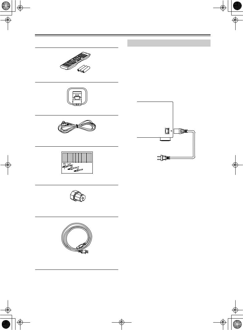
Supplied Accessories
Make sure you have the following accessories:
Remote Controller & Three Batteries (AA/R6)
AM Loop Antenna
Indoor FM antenna
(connector type varies from country to country)
Front Left |
Front Left |
SP-B / Zone 2 |
Left |
SP-B / Zone 2 |
Left |
Front Right |
Front Right |
SP-B / Zone 2 |
Right |
SP-B / Zone 2 |
Right |
Surround Left |
Surround Left |
Surround Right |
Surround Right |
Center |
Center |
Surround Back |
Left |
Surround Back |
Left |
Zone 2 |
Left |
Zone 2 |
Left |
Surround Back Right |
Surround Back Right |
Zone 2 |
Right |
Zone 2 |
Right |
Front Left |
Front Left |
SP-B / Zone 2 |
Left |
SP-B / Zone 2 |
Left |
Front Right |
Front Right |
SP-B / Zone 2 |
Right |
SP-B / Zone 2 |
Right |
Surround Left |
Surround Left |
Surround Right |
Surround Right |
Center |
Center |
Surround Back |
Left |
Surround Back |
Left |
Zone 2 |
Left |
Zone 2 |
Left |
Surround Back Right |
Surround Back Right |
Zone 2 |
Right |
Zone 2 |
Right |
|
|
|
|
1 |
|
|
|
|
2 |
|
|
|
|
|
|
|
|
|
|
|
|
|
|
|
|
|
|
|
|
||
|
|
|
|
|
|
|
|
|
|
|
|
|
|
|
|
|
|
|
|
|
|
|
|
|
|
|
|
|
|
||
|
|
|
|
|
|
|
|
|
|
|
|
|
|
|
3 |
|
|
|
|
|
|
|
|
|
|
|
|
|
|
|
|
Speaker Cable |
|
|
|
|
|
|
|
|
|
|
|
|
|
|
|
|
|
|
|
|
|
|
|
|
|
|
|
|
|||
Connecting the Supplied Power Cord
Plug the supplied power cord into this AC INLET.
•Do not use a power cord other than the one supplied with the DTR-10.5. The power cord supplied is designed for use with the DTR-10.5 and should not be used with any other device.
•Never have the power cord disconnected from the DTR-10.5 while the other end is plugged into the wall outlet. Doing so may cause an electric shock.
Always connect by plugging into the wall outlet last and disconnect by unplugging from the wall outlet first.
Power Cord (supplied)
AC INLET
DO NOT connect the power cord at this time.
Speaker Labels
Terminal Wrench
A wrench to screw/unscrew the speaker terminal cap.
Power Cord ( The shape of the plug varies depending on the region where the model is intended.)
8
Before Using the DTR-10.5
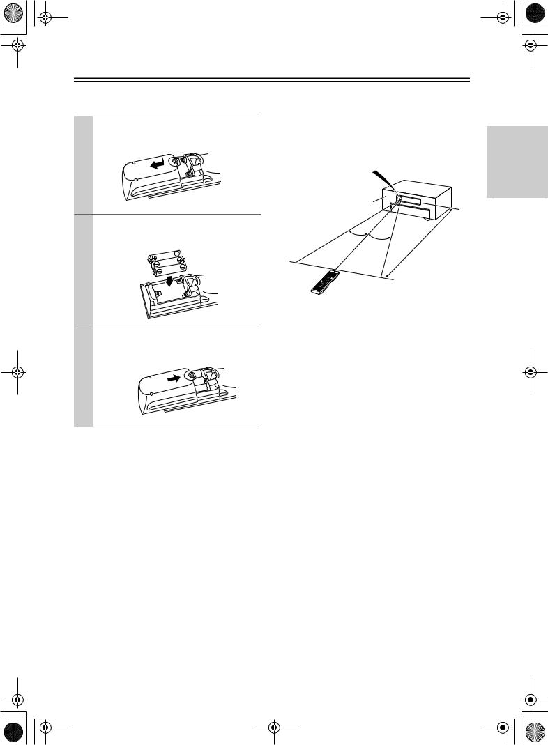
Installing the Batteries |
|
Using the Remote Controller |
1 To open the battery compartment, press the small hollow and slide off the cover.
2 Insert the three supplied batteries (AA/R6) in accordance with the polarity diagram inside the battery compartment.
3 Put the cover onto the remote controller and slide it shut.
Notes:
•The supplied batteries should last for about six months, although this will vary with usage.
•If the remote controller doesn’t work reliably, try replacing the batteries.
•Don’t mix new and old batteries, or different types of batteries.
•If you intend not to use the remote controller for a long time, remove the batteries to prevent possible leakage and corrosion.
•Expired batteries should be removed as soon as possible to prevent damage from leakage or corrosion.
To use the remote controller, point it at the DTR-10.5’s remote control sensor, as shown below. The DTR-10.5’s [Standby] indicator flashes while a signal is being received from the remote controller.
Remote control sensor
DTR-10.5
Standby indicator
30˚ |
|
|
(5 |
m) |
|
. |
|
||
30˚ |
|
|
|
|
|
.16 |
ft |
|
|
|
|
|
|
|
|
ox |
|
|
|
|
Appr |
|
|
|
Notes:
•The remote controller may not work reliably if the DTR-10.5 is subjected to bright light, such as direct sunlight or inverter-type fluorescent lights. Keep this in mind when installing the DTR-10.5.
•If another remote controller of the same type is used in the same room, or the DTR-10.5 is installed close to equipment that uses infrared rays, the remote controller may not work reliably.
•Don’t put anything, such as a book, on the remote controller, because the buttons may be pressed inadvertently, thereby draining the batteries.
•The remote controller may not work reliably if the DTR-10.5 is installed in a rack behind colored glass doors. Keep this in mind when installing the DTR-10.5.
•The remote controller will not work if there’s an obstacle between it and the DTR-10.5’s remote control sensor.
•You can set the transmission signal format to infrared (IR), or radio frequency (RF) for use with the optional RF Receiver. This is useful when, for example, the DTR-10.5 is installed in a rack or is not in line of sight of the remote controller.
•To select AMP mode, press the scroll wheel. “AMP” appears on the display.
Getting Started
9
Before Using the DTR-10.5—Continued
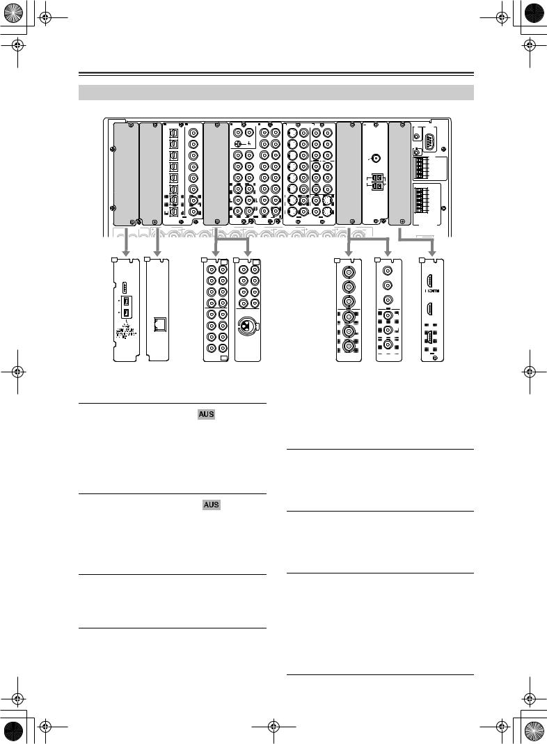
Types of the DTR-10.5 Option Boards
The following option boards are available for the DTR-10.5 as of October 2004.
A |
B |
|
C DIGITAL IN |
D DIGITAL IN |
E |
MULTI |
F |
AUDIO IN |
G |
|
H S VIDEO |
VIDEO |
I |
COMPONENT |
J |
|
K |
L |
|
|
|
-CH |
|
VIDEO |
|
12 V |
RS232 |
||||||||||||||
|
|
|
OPTICAL |
COAXIAL |
FR |
FL IN 1 |
R |
L |
R |
L |
IN |
IN |
IN 1 |
IN 2 |
COMPONENT VIDEO |
ANTENNA |
HDMI |
|||
|
|
|
|
|
|
|
|
|
|
|
|
|
|
|
(HD/BNC) |
IN |
|
TRIGGER |
|
|
|
|
|
|
|
|
|
PH |
|
4 |
|
|
|
|
|
|
|
OUT |
|
||
|
|
|
1 |
1 |
|
|
|
|
1 |
|
|
Y |
|
|
|
|
|
|||
|
|
|
|
|
|
|
|
|
|
Y |
|
|
|
|
||||||
|
|
|
|
|
|
|
|
|
|
|
|
|
|
|
|
|
IN 1 |
E |
|
|
|
|
|
|
|
SUB |
C |
|
|
|
|
|
|
|
|
|
|
|
|
|
|
|
|
|
2 |
2 |
|
|
|
|
5 |
|
2 |
|
|
PB |
|
|
|
|
|
|
|
|
|
|
|
|
|
|
GND |
|
|
|
|
|
|
|
|
|
|
|
|
|
|
|
|
|
SR |
SL |
R |
L |
|
|
|
|
|
|
|
PB |
|
|
|
|
|
|
“Net-Tune” |
3 |
3 |
|
|
1 |
|
6 |
|
3 |
|
|
PR |
|
|
|
|
|
IR IN |
|
|
is a trademark of |
|
|
|
|
|
|
|
|
FM |
|
|
|||||||
|
|
Onkyo Corporation. |
|
|
|
|
|
|
|
|
|
|
|
|
|
|
|
|
+12V DC PWR SUPPLY |
|
|
|
|
|
|
SBR |
SBL |
|
|
|
|
|
|
OUT 1 |
IN 3 |
|
|
75 |
|
|
|
|
|
|
|
|
|
|
|
|
|
|
|
|
|
|
|
20mA MAX. |
||||
|
|
|
|
|
|
|
|
|
|
|
|
|
|
|
|
PR |
|
IN 2 |
|
GND |
|
|
|
4 |
4 |
|
|
2 |
|
7 |
|
4 |
|
|
Y |
|
|
|
|
||
|
|
|
|
|
|
|
|
|
|
|
|
|
MAIN |
|||||||
|
|
|
|
|
FR |
FL |
|
|
|
|
|
|
|
|
|
OUT |
|
|
|
ZONE 2 |
|
|
|
|
|
|
|
|
|
|
|
|
|
|
|
|
|
|
|||
|
|
ETHERNET |
5 |
5 |
|
|
3 |
|
8 |
|
5 |
|
|
PB |
|
|
|
|
|
ZONE 3 |
|
|
|
|
|
|
|
|
|
|
|
|
|
|
|||||||
|
|
(Net-Tune) |
|
|
|
|
|
|
|
|
|
|
|
|
|
Y |
AM |
|
|
|
|
|
|
|
|
|
|
|
|
|
|
|
|
|
|
|
|
|
|
||
|
|
|
|
|
SUB |
C |
|
|
|
|
|
|
|
|
|
|
|
|
|
|
|
|
|
6 |
6 |
|
|
1 |
|
9 |
|
6 |
|
|
PR |
|
|
|
|
|
A 200mA MAX. |
|
|
|
|
|
|
|
|
|
|
|
|
|
|
|
|
|
|
|
|
|
|
|
|
|
|
SR |
SL |
|
|
|
|
|
|
|
|
|
PB |
|
|
|
B 100mA MAX. |
|
|
|
1 |
1 |
|
|
2 |
|
4 |
|
1 |
|
3 |
|
|
|
|
|
|
C 100mA MAX. |
|
|
|
|
|
|
|
|
|
|
|
|
|
|
GND |
||||||
|
|
|
|
|
|
|
|
|
|
|
|
|
|
|
|
|
|
|
|
|
|
|
|
|
|
SBR |
SBL |
|
|
|
|
|
|
|
|
|
|
|
|
|
D 100mA MAX. |
|
|
|
|
|
|
|
|
|
|
|
|
|
|
|
|
PR |
|
|
|
E TOTAL |
|
|
|
2 |
2 |
|
|
3 |
|
5 |
|
2 |
|
4 |
|
|
|
|
|
|
100mA MAX. |
|
|
|
OUT |
|
R |
L |
OUT R |
L |
OUT |
OUT |
|
OUT |
|
|
|
|
MULTI |
|
|
|
S VIDEO |
VIDEO |
VIDEO |
S VIDEO |
|
|
|
|
|
-CH |
|
|
|
|
|
|
|
12V |
|
|
|
|
IN 2 |
|
|
|
|
|
|
|
|
|
|
|
SURR BACK R (ASSIGNABLE) |
|
|
|
|
|
SURR BACK L (ASSIGNABLE) |
TRIGGER OUT |
||
|
PRE OUT A |
SURR R |
FRONT R |
|
|
CENTER |
FRONT L |
SURR L |
||||
|
|
|
|
|
|
|
|
|
(SINGLE) |
|
AC INLET |
|
FRONT |
SURR |
SURR |
|
|
|
|
|
|
|
|
|
|
|
|
BACK |
|
|
|
|
|
|
|
|
|
|
A |
B |
E |
-CH |
E |
|
-CH |
J |
J |
|
L |
|
|
MULTI |
|
|
MULTI |
|
|
|
|
|
|
|
FR |
FL IN 1 |
FR |
FL |
IN 1 |
COMPONENT VIDEO |
COMPONENT VIDEO |
HDMI |
|
|
|
|
|
|
|
|
(HD/BNC) |
IN |
IN 4 |
|
|
|
|
|
|
|
|
|
Y |
Y |
|
|
|
|
|
|
|
|
|
|
IN 1 |
|
|
|
SUB |
C |
SUB |
|
C |
|
|
|
|
|
|
SR |
SL |
SR |
|
SL |
|
PB |
PB |
|
|
|
|
|
|
|
|||||
|
|
“Net-Tune” |
|
|
|
|
|
|
|
|
|
|
is a trademark of |
|
|
|
|
|
|
|
|
|
|
Onkyo Corporation. |
|
|
|
|
|
|
|
|
|
|
SBR |
SBL |
SBR |
|
SBL |
|
|
PR |
|
|
|
|
|
|
|
|
|
PR |
|
|
|
|
|
|
|
|
|
|
|
IN 2 |
|
|
|
|
|
|
|
|
|
|
|
|
|
|
FR |
FL |
|
|
|
OUT |
|
OUT |
|
|
|
ETHERNET |
|
|
|
|
|
|
Y |
|
|
|
(Net-Tune) |
|
|
|
|
|
Y |
|
|
|
|
|
|
|
|
|
|
|
|
|
|
|
SUB |
C |
|
|
|
|
|
|
|
|
|
SR |
SL |
|
|
|
|
PB |
PB |
|
|
|
|
|
|
|
|
|
|||
|
|
SBR |
SBL |
DIGITAL IN |
|
|
PR |
|
||
|
|
|
|
(BALANCED) |
|
PR |
|
|||
|
|
|
|
AES/EBU |
|
|
|
|
||


 OUT
OUT 


MULTI
-CH
IN 2
C-LINK C-NET-A |
C-MULTI C-AES |
C-CPNT-BNC C-CPNT-RCA C-HDMI |
Distributed regions (as of October 2004)  (the United States)
  (Australia)
Product number: C-LINK 
Provides i.LINK (AUDIO) terminals. Two input terminals are available. This option board will be inserted into slot A on the DTR-10.5.
These connectors are for connecting to an i.LINK (AUDIO)-ready device using a 4-pin (S400) i.LINK (AUDIO) cable. The DTR-10.5 complies with the standards on audio only transimissions.
Product number: C-NET-A 
Provides one Ethernet port for the Net-Audio connection. Connecting the network server to the port allows you to enjoy music stored on your PC or delivered from an Internet radio broadcast.
This option board will be inserted into slot B on the DTR-10.5.
Product number: C-MULTI 
Provides two analog multichannel input terminal sets. This option board will be inserted into slot E on the DTR-10.5.
Product number: C-AES 
Provides one analog multichannel input terminal set and one AES/EBU digital audio input jack.
The multichannel connector is for connecting components with a multichannel output. The DIGITAL IN (BALANCED) AES/EBU terminal is for connecting the DVD player and other devices equipped with the XLR (balanced) type digital audio output terminal.
This option board will be inserted into slot E on the DTR-10.5.
Product number: C-CPNT-BNC 
Provides BNC-type component video terminals. One input terminal set and one output terminal set are available. This option board will be inserted into slot J on the DTR-10.5.
Product number: C-CPNT-RCA 
Provides RCA-type component video terminals. One input terminal set and one output terminal set are available. This option board will be inserted into slot J on the DTR-10.5.
Product number: C-HDMI 
Provides HDMI terminals. Two input terminals and one output terminal are available.
This option board will be inserted into slot L on the DTR-10.5.
This interface can transfer digital audio and video signals simultaneously. The terminal can be connected to the HDMI terminal on components such as DVD player, set top box (B tuner), projector, and digital TV.
10
Before Using the DTR-10.5—Continued
Installing the Option Boards
The option boards should be installed in their individual designated slots. Installing the option board a different slot may cause failure.
1 Turn off the power and unplug the power cord both from the DTR-10.5 and electrical outlet.
Be sure to turn off the power of the DTR-10.5. Inserting or removing an option board with the DTR-10.5 turned on may cause failure.
2 Take the option board out from the package carefully.
The option board incorporates many components, terminals and connectors along with solderings on its surface. Touching the board with your fingers may cause failure or damage from static electricity, incorrect contact and so on. When handling the board, be sure to hold the outer part or panel section of the board without touching the board surface.
Board surface
B
TuneNet-)( |
ETHERNET |
3 Check the alphabet letter on the option board.
The alphabet letter is printed at the top left corner of the panel section.
B
“Net |
-Tune” |
|
|
B |
||
|
|
ark of |
||||
is a tradem |
|
ration. |
||||
Onkyo Corpo |
|
|
|
|||
|
ETH |
ERNET |
|
|||
|
|
|
|
) |
|
|
|
(Net-Tune |
|
|
|||
4 Remove the sub-panel with the same alphabet letter as your option board from the back of the DTR-10.5.
Use the supplied Allen wrench to loosen the screw gradually, while holding the sub-panel so that the panel will not drop down.
The sub-panels are fixed to the DTR-10.5 with two screws at the top and bottom, while the panel that covers slots [H] and [I] is fixed with four screws at the top and bottom. Keep the removed screws for fixing the option board.
B
A
|
S400 |
AUDIO |
|
K logo is |
a |
The i.LIN s of Sony |
|
trademark n, registered |
|
Corporatio and other |
|
in the U.S.. |
|
countries |
|
L |
|
|
|
CENTER |
|
R |
|
|
FRONT |
SUB |
FER |
WOO |
|
|
E
|
|
|
D |
DIGITAL |
IN |
C |
DIGITAL |
IN |
|
COAXIAL |
|
|
OPTICAL |
|
|
|
|
B |
|
|
1 |
|
|
|
1 |
|
|
|
|
|
|
|
2 |
|
|
|
2 |
|
|
|
|
|
|
|
3 |
|
|
|
3 |
|
|
|
|
|
|
|
4 |
|
|
|
4 |
|
|
|
|
|
|
|
5 |
|
|
|
5 |
|
|
|
|
|
|
|
6 |
|
|
|
6 |
|
|
|
|
1 |
1 |
2 |
2 |
OUT |
|
|
|
|
(ASSIGNABL |
E) |
|
|
|
|
|
|
|
|
|
L |
|
|
|
|
|
|
(SINGLE) |
|
|
|
|
|
|
|
|
|
|
SURR |
R |
|
|
|
|
|
|
|
|
R |
|
|
SURR BAC |
K R |
|
|
|
SUBWOO |
FER |
|
|
|
|
K |
PRE OU |
T A |
|
|
|
SURR |
SURR BACE) |
|
|
|
|
|
(ASSIGNABL |
|
|
|
|
|
|
5 Insert the option board along the rail softly. When the board comes to the position where it stops but does not cover the slot completely, push the board forward a little bit more strongly.
A
|
|
|
|
S400 |
AUDIO |
|
|
||
K logo is |
a |
|||
The i.LIN |
of |
Sony |
||
trademarks |
|
egistered |
||
Corporation, r |
|
other |
||
in the U.S.. and |
|
|
||
countries |
|
|
|
|
E
|
|
D |
DIGITAL |
IN |
C |
DIGITAL |
IN |
COAXIAL |
|
|
OPTICAL |
|
|
|
|
|
1 |
|
|
|
1 |
|
|
|
2 |
B |
|
2 |
|
3 |
|
3 |
|
4 |
|
4 |
|
is“Naettr-Taudneem”ark otiof |
n. |
Onkyo Corpora |
|
5 |
|
5 |
|
6 |
|
6 |
|
ETHERNET) |
(Net-Tune |
1 |
1 |
2 |
2 |
OUT |
(ASSIGNABL |
E) |
|
|
|
L |
|
|
|
|
|
|
|
(SINGLE) |
|
|
|
|
L |
|
|
|
|
|
SURR |
R |
|
CENTER |
R |
|
SURR BAC |
K R |
|
|
|
|
|
|
|
|
|
|
|
|
|
|
SUBWOO |
FER |
|
|
|
|
|
K |
|
|
|
|
R |
|
SURR |
SURR BACE) |
PRE OU |
|
|
|
|
SUB |
(ASSIGNABL |
|
|
|
|
|
FRONT |
WOO |
|
|
|
|
|
|
6 Fix the option board firmly to the DTR-10.5 using the removed screws.
Be sure to tighten the screws firmly to the DTR-10.5. If the screws are loose, contact failures for ground or signal wires may occur at the section between the DTR-10.5’s slot terminal and the option board, which may cause the DTR-10.5 or board to fail.
A
|
S400 |
AUDIO |
|
|
a |
i.LINK logo isny |
|
The marks of So |
ered |
Ctraodrpeoration, rdegoisthert |
|
in the U.S.. an |
|
countries |
|
L |
|
|
|
CENTER |
|
R |
|
|
FRONT |
SUB |
FER |
WOO |
|
|
E
|
|
|
|
D |
DIGITAL |
IN |
|
C |
DIGITAL |
IN |
|
COAXIAL |
|
|
|
OPTICAL |
|
|
|
|
B |
|
|
|
1 |
|
|
|
|
1 |
|
|
|
|
|
|
|
|
2 |
|
|
|
|
2 |
|
|
|
|
|
|
|
|
3 |
|
|
is“Naettr-Taudneem”ark otiof |
|
3 |
|
|
|
|
n. |
|
|
|
|
|
|
Onkyo Corpora |
|
|
|
4 |
|
|
|
|
4 |
|
|
|
|
|
|
|
|
5 |
|
|
|
|
5 |
|
|
|
|
ETHERNET) |
|
|
|
|
|
|
(Net-Tune |
|
|
|
|
|
|
|
|
|
|
6 |
|
|
|
|
6 |
|
|
|
|
1 |
1 |
2 |
2 |
OUT |
|
|
|
|
(ASSIGNABL |
E) |
|
|
|
|
|
|
|
|
|
L |
|
|
|
|
|
|
(SINGLE) |
|
|
|
|
|
|
|
|
|
|
SURR |
R |
|
R |
|
|
SURR BAC |
K R |
|
|
|
SUBWOO |
FER |
|
|
|
|
K |
PRE OU |
T A |
|
|
|
SURR |
SURR BACE) |
|
|
|
|
|
(ASSIGNABL |
|
|
|
|
|
|
Getting Started
11
Index Parts and Facilities
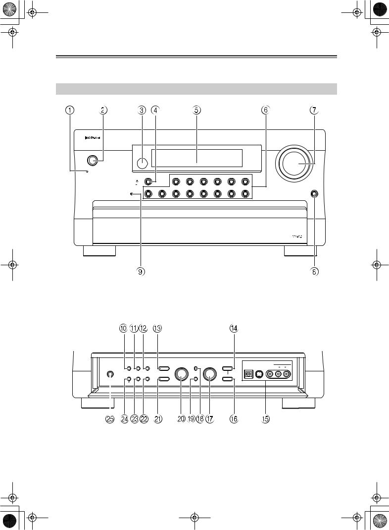
Here is an explanation of the controls and displays on the front panel of the DTR-10.5.
The specifications for your model may differ due to regional requirements.
Front Panel
Master Volume
 Standby/On
Standby
Display |
|
Tape 1 |
Tape 2 |
Tuner |
Phono |
CD |
Net Audio |
|
Rec/Zone 3 (Red) |
|
|
|
|
|
|
|
|
Main (Blue) |
|
|
|
|
|
|
|
|
Zone 2 (Green) |
|
|
|
|
|
|
|
|
DVD |
Video 1 |
Video 2 |
Video 3 |
Video 4 |
Video 5 |
Video 6 |
Video 7 |
Open |
Pure Audio |
|
|
|
|
|
|
|
|
Inner panel
Listening |
Audio |
|
|
|
|
|
|
|
|
Mode |
Selector |
Tone |
Zone 2 |
Select/Preset |
Setup |
Control/Tuning |
Rec/Zone 3 |
|
Video 7 Input |
|
|
|
|
|
Digital |
S Video |
Video |
L |
Audio |
R |
Phones |
|
|
|
|
|
|
|
|
|
|
Tuning |
|
|
|
|
|
|
|
|
|
|
Mode |
Memory |
Dimmer |
Level |
Exit |
Level |
|
|
|
|
|
|
Clear |
|
|
Push To Enter |
Push To Enter |
|
|
|
|
|
12
Index Parts and Facilities—Continued
For further operational instructions, see the pages indicated in brackets [ ].
1Standby indicator [9, 52]
Lights when the DTR-10.5 is in the standby state and when a signal is received from the remote controller.
2Standby/On button [52]
Press this button, the DTR-10.5 turns on and the display lights up. If pressed again, the DTR-10.5 returns to the standby state. In the standby state, the display is turned off and the DTR-10.5 cannot be operated.
3 Remote control sensor [9]
4Display button [56]
Press to display information about the current input source signal. Each time you press the [Display] button, the screen changes to show you different information concerning the input signal.
5 Front display
6Input source buttons and indicators (DVD, Video 1-7, Tape 1-2, Tuner, Phono, CD, and Net Audio) [52]
Press these buttons to select the input source for the main zone.
After selecting the input source, the corresponding indicator turns blue. If you select Zone 2, the indicator turns green. If you select Zone 3 or Rec, the indicator turns red.
7Master Volume dial [52]
Use to control the volume in the main zone. The volume for the remote zone (Zone 2 and Zone 3) is independent.
8Open button
Press this button to open the front panel door.
9Pure Audio indicator
Lights during pure audio playback.
Inner panel
0Listening Mode button [61]
Press this button to enter the setup mode for the listening mode. Turning the [Select/Preset] allows you to select the listening mode. To confirm your selection and exit the setup mode, press the [Select/ Preset].
AAudio Selector button [57]
Press this button to enter the audio selector mode. Turning the [Select/Preset] allows you to select the audio mode.
BTone button [54]
Press this button to enter the tone adjustment mode. Turning the [Select/Preset] allows you to select the channel to adjust the tone. To adjust the tone level, turn the [Control/Tuning].
CZone 2 button [68]
Press this button to enter the Zone 2 configuration mode. Turning the [Select/Preset] allows you to select the input source for Zone 2. Also, if you want to configure other Zone 2 settings such as standby/ on setting, listening mode, volume adjustment, audio selector mode, and display settings, press this button first.
DRec/Zone 3 button [68, 70]
Press this button to enter the Rec/Zone 3 mode. Turning the [Control/Tuning] allows you to select the input source for the Rec mode or Zone 3. Also, if you want to configure the setting for Zone 3 including standby/on setting or volume adjustment, press this button first.
Note:
Recording and Zone 3 operations uses the same circuit and therefore cannot be used at the same time.
EVideo 7 Input terminals [40]
For connecting a video camera or game device.
F Zone 3 Level button [68]
Press this button to enter the volume adjustment mode for Zone 3. Turning the [Select/Preset] allows you to adjust the volume.
GControl/Tuning dial
When the input source is FM or AM, turning this jog dial allows you to select the frequency to receive. When used with other buttons, this [Control/ Tuning] dial is used to select the mode settings or values. Also the dial is pressed to confirm the settings or values you select.
HSetup button [86]
Press this button to enter the setup mode. First, select the parameter to change by turning the [Select/Preset] and press the [Select/Preset] to confirm the parameter. Then, change the parameter value by turning the [Control/Tuning] and press the [Control/Tuning] to confirm the value.
Getting Started
13
Index Parts and Facilities—Continued
IExit button [86]
Press this button to return to the last menu. To exit from the setup mode, press the [Setup] button again.
JSelect/Preset dial
When the input source is FM or AM, turning this jog dial allows you to switch between your preset stations. When used with other buttons, the [Select/ Preset] dial is used to select the mode settings or parameters. Also the dial is pressed to confirm the settings or parameters you select.
KZone 2 Level button [68]
Pressing this button enters the volume adjustment mode for Zone 2. To adjust volume, turn the [Select/ Preset].
LDimmer button [54]
Press to set the brightness of the front display. There are four settings available: normal, dark, very dark, and volume only.
MMemory button [63]
Press to assign the radio station, to which you are currently tuned, as a preset channel or press to delete a previously preset station.
NTuning Mode button [62, 63]
This button is used to select the Auto or Manual Tuning Mode.
OPhones jack [54]
This is a standard stereo jack for connecting stereo headphones.
14
Index Parts and Facilities—Continued
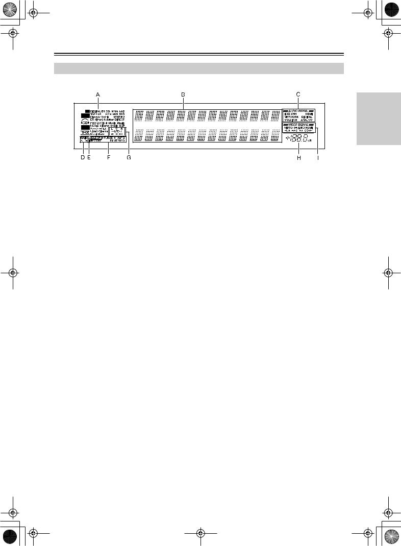
Front Panel Display
AListening mode or input format indicators
One of these indicators lights to show the format of the current input source. In addition, one of the listening mode indicators lights to indicate the current listening mode.
BMultifunction display
During normal operation, shows the current input source. When the FM or AM input is selected, shows the frequency and preset number. When the [Display] button is pressed, shows the listening mode and input source format.
CAudio input signal path indicators
Shows from which terminal the audio input signal is coming.
DMAIN A/B indicators
Indicates which room is currently in use.
ESLEEP indicator
Lights when the sleep timer is turned on.
Getting Started
FTuning indicators
AUTO indicator
Lights when receiving FM broadcasts in the stereo mode. Turns off when placed into the monaural mode.
 TUNED
TUNED indicator
Lights when a radio station is being received.
MEMORY indicator
Lights when the [Memory] button is pressed to preset a radio station.
FM STEREO indicator
Lights when an FM broadcast station is being received in stereo. Turns off when placed into the monaural mode.
GProgram format display
When the input source is DVD video, Super Audio CD, or compressed digital audio signal such as Dolby Digital and DTS, the channels corresponding to the input source light.
HVolume display
Shows the volume level.
IVideo input signal path indicators
Shows from which terminal the video input signal is coming.
15

Index Parts and Facilities—Continued
Rear Panel
USA and Canadian models
A |
|
B |
C DIGITAL IN |
D DIGITAL IN |
E |
MULTI |
F |
|
AUDIO IN |
G |
|
H S VIDEO |
VIDEO |
I |
COMPONENT |
J |
|
K |
L |
|
|
|
- CH |
|
|
VIDEO |
|
12 V |
RS232 |
||||||||||||||
|
|
|
OPTICAL |
COAXIAL |
FR |
FL IN 1 |
R |
|
L |
R |
L |
IN |
IN |
IN 1 |
IN 2 |
COMPONENT VIDEO |
ANTENNA |
HDMI |
|||
|
|
|
|
|
|
|
|
|
|
|
|
|
|
|
|
(HD/BNC) |
IN |
|
TRIGGER |
||
|
|
|
|
|
|
|
PH |
|
4 |
|
|
|
|
|
|
|
|
OUT |
|
||
|
|
|
1 |
1 |
|
|
|
|
|
1 |
|
|
Y |
|
|
|
|
|
|||
|
|
|
|
|
|
|
|
|
|
|
Y |
|
|
|
|
||||||
|
|
|
|
|
|
|
|
|
|
|
|
|
|
|
|
|
|
IN 1 |
|
E |
|
|
|
|
|
|
SUB |
C |
|
|
|
|
|
|
|
|
|
|
|
|
|
|
|
|
|
|
2 |
2 |
|
|
|
|
5 |
|
|
2 |
|
|
PB |
|
|
|
|
|
|
|
|
|
|
|
|
|
|
|
GND |
|
|
|
|
|
|
|
|
|
|
|
|
|
|
|
|
|
SR |
SL |
R |
L |
|
|
|
|
|
|
|
|
PB |
|
|
|
|
|
|
“Net-Tune” |
3 |
3 |
|
|
1 |
|
6 |
|
|
3 |
|
|
PR |
|
|
|
|
|
IR IN |
|
|
is a trademark of |
|
|
|
|
|
|
|
|
|
FM |
|
|
|||||||
|
|
Onkyo Corporation. |
|
|
|
|
|
|
|
|
|
|
|
|
|
|
|
|
|
+12V DC PWR SUPPLY |
|
|
|
|
|
|
SBR |
SBL |
|
|
|
|
|
|
|
OUT 1 |
IN 3 |
|
|
75 |
|
|
|
|
|
|
|
|
|
|
|
|
|
|
|
|
|
|
|
|
20mA MAX. |
||||
|
|
|
|
|
|
|
|
|
|
|
|
|
|
|
|
|
PR |
|
IN 2 |
|
GND |
|
|
|
4 |
4 |
|
|
2 |
|
7 |
|
|
4 |
|
|
Y |
|
|
|
|
MAIN |
|
|
|
|
|
|
FR |
FL |
|
|
|
|
|
|
|
|
|
|
OUT |
|
|
|
ZONE 2 |
|
|
|
|
|
|
|
|
|
|
|
|
|
|
|
|
|
|
|
|||
|
|
ETHERNET |
5 |
5 |
|
|
3 |
|
8 |
|
|
5 |
|
|
PB |
|
|
|
|
|
ZONE 3 |
|
|
|
|
|
|
|
|
|
|
|
|
|
|
|
|||||||
|
|
(Net-Tune) |
|
|
|
|
|
|
|
|
|
|
|
|
|
|
Y |
AM |
|
|
|
|
|
|
|
|
|
|
|
|
|
|
|
|
|
|
|
|
|
|
|
||
|
|
|
|
|
SUB |
C |
|
|
|
|
|
|
|
|
|
|
|
|
|
|
|
|
|
|
6 |
6 |
|
|
1 |
|
9 |
|
|
6 |
|
|
PR |
|
|
|
|
|
A 200mA MAX. |
|
|
|
|
|
|
|
|
|
|
|
|
|
|
|
|
|
|
|
|
|
|
|
|
|
|
|
SR |
SL |
|
|
|
|
|
|
|
|
|
|
PB |
|
|
|
B 100mA MAX. |
|
|
|
1 |
1 |
|
|
2 |
|
4 |
|
|
1 |
|
3 |
|
|
|
|
|
|
C 100mA MAX. |
|
|
|
|
|
|
|
|
|
|
|
|
|
|
|
GND |
||||||
|
|
|
|
|
|
|
|
|
|
|
|
|
|
|
|
|
|
|
|
|
|
|
|
|
|
|
SBR |
SBL |
|
|
|
|
|
|
|
|
|
|
|
|
|
|
D 100mA MAX. |
|
|
|
|
|
|
|
|
|
|
|
|
|
|
|
|
|
PR |
|
|
|
E TOTAL |
|
|
|
2 |
2 |
|
|
3 |
|
5 |
|
|
2 |
|
4 |
|
|
|
|
|
|
100mA MAX. |
|
|
|
|
OUT |
|
|
R |
L |
OUT |
R |
L |
|
OUT |
OUT |
|
|
|
|
OUT |
|
|
|
|
|
|
|
|
MULTI |
|
|
|
|
|
S VIDEO |
VIDEO |
VIDEO |
S VIDEO |
|
|
|
|
|
|
|
|
|
|
|
|
- CH |
|
|
|
|
|
|
|
|
|
|
|
|
|
|
12V |
|
|
|
|
|
|
IN 2 |
|
|
|
|
|
|
|
|
|
|
|
|
|
|
|
|
|
|
SURR R |
SURR BACK R (ASSIGNABLE) |
FRONT R |
|
CENTER |
|
FRONT L |
SURR BACK L (ASSIGNABLE) |
|
SURR L |
|
|
|
TRIGGER OUT |
|||||
|
PRE OUT A |
|
|
|
|
|
|
|
|
||||||||||||
|
|
|
|
|
|
|
|
|
|
|
|
|
(SINGLE) |
|
|
|
|
|
AC INLET |
|
|
FRONT |
SURR |
SURR |
|
|
|
|
|
|
|
|
|
|
|
|
|
|
|
|
|
|
|
|
|
BACK |
|
|
|
|
|
|
|
|
|
|
|
|
|
|
|
|
|
|
|
L |
|
|
A |
|
SPEAKERS A |
|
|
|
|
|
|
|
|
|
|
|
|
|
AC OUTLET |
|
|
|
|
|
|
AC 120V |
60Hz |
R |
|
|
|
|
SWITCHED |
|
|
|
|
|
120W 1A MAX. |
||
|
|
|
|
|
||
|
|
|
B |
|
SPEAKERS B |
|
CENTER |
SUB |
SUB |
FRONT R (BTL) |
FRONT L (BTL) |
|
|
|
WOOFER |
WOOFER |
|
|
MODEL NO. DTR-10.5 |
|
|
|
PRE |
|
UDD |
||
|
|
OUT B |
|
|
|
|
Australian model
A |
B |
|
C DIGITAL IN |
D DIGITAL IN |
E |
MULTI |
F |
|
AUDIO IN |
G |
|
H S VIDEO |
VIDEO |
I |
COMPONENT |
J |
|
K |
L |
|
|
|
- CH |
|
|
VIDEO |
|
12 V |
RS232 |
||||||||||||||
|
|
|
OPTICAL |
COAXIAL |
FR |
FL IN 1 |
R |
|
L |
R |
L |
IN |
IN |
IN 1 |
IN 2 |
COMPONENT VIDEO |
ANTENNA |
HDMI |
|||
|
|
|
|
|
|
|
|
|
|
|
|
|
|
|
|
(HD/BNC) |
IN |
|
TRIGGER |
|
|
|
|
|
|
|
|
|
PH |
|
4 |
|
|
|
|
|
|
|
|
OUT |
|
||
|
|
|
1 |
1 |
|
|
|
|
|
1 |
|
|
Y |
|
|
|
|
|
|||
|
|
|
|
|
|
|
|
|
|
|
|
|
|
|
|
|
Y |
|
IN 1 |
E |
|
|
|
|
|
|
SUB |
C |
|
|
|
|
|
|
|
|
|
|
|
|
|
|
|
|
|
|
2 |
2 |
|
|
|
|
5 |
|
|
2 |
|
|
PB |
|
|
|
|
|
|
|
|
|
|
|
|
|
|
|
GND |
|
|
|
|
|
|
|
|
|
|
|
|
|
|
|
|
|
SR |
SL |
R |
L |
|
|
|
|
|
|
|
|
PB |
|
|
|
|
|
|
“Net-Tune” |
3 |
3 |
|
|
1 |
|
6 |
|
|
3 |
|
|
PR |
|
|
|
|
|
IR IN |
|
|
is a trademark of |
|
|
|
|
|
|
|
|
|
FM |
|
|
|||||||
|
|
Onkyo Corporation. |
|
|
|
|
|
|
|
|
|
|
|
|
|
|
|
|
|
+12V DC PWR SUPPLY |
|
|
|
|
|
|
SBR |
SBL |
|
|
|
|
|
|
|
OUT 1 |
IN 3 |
|
|
75 |
|
|
|
|
|
|
|
|
|
|
|
|
|
|
|
|
|
|
|
|
20mA MAX. |
||||
|
|
|
|
|
|
|
|
|
|
|
|
|
|
|
|
|
PR |
|
IN 2 |
|
GND |
|
|
|
4 |
4 |
|
|
2 |
|
7 |
|
|
4 |
|
|
Y |
|
|
|
|
||
|
|
|
|
|
|
|
|
|
|
|
|
|
|
MAIN |
|||||||
|
|
|
|
|
FR |
FL |
|
|
|
|
|
|
|
|
|
|
OUT |
|
|
|
ZONE 2 |
|
|
ETHERNET |
5 |
5 |
|
|
3 |
|
8 |
|
|
5 |
|
|
PB |
|
|
|
|
|
ZONE 3 |
|
|
|
|
|
|
|
|
|
|
|
|
|
|
|
|||||||
|
|
(Net-Tune) |
|
|
|
|
|
|
|
|
|
|
|
|
|
|
Y |
AM |
|
|
|
|
|
|
|
|
|
|
|
|
|
|
|
|
|
|
|
|
|
|
|
||
|
|
|
|
|
SUB |
C |
|
|
|
|
|
|
|
|
|
|
|
|
|
|
|
|
|
|
6 |
6 |
|
|
1 |
|
9 |
|
|
6 |
|
|
PR |
|
|
|
|
|
A 200mA MAX. |
|
|
|
|
|
|
|
|
|
|
|
|
|
|
|
|
|
|
|
|
|
|
|
|
|
|
|
SR |
SL |
|
|
|
|
|
|
|
|
|
|
PB |
|
|
|
B 100mA MAX. |
|
|
|
1 |
1 |
|
|
2 |
|
4 |
|
|
1 |
|
3 |
|
|
|
|
|
|
C 100mA MAX. |
|
|
|
|
|
|
|
|
|
|
|
|
|
|
|
GND |
||||||
|
|
|
|
|
|
|
|
|
|
|
|
|
|
|
|
|
|
|
|
|
|
|
|
|
|
|
SBR |
SBL |
|
|
|
|
|
|
|
|
|
|
|
|
|
|
D 100mA MAX. |
|
|
|
|
|
|
|
|
|
|
|
|
|
|
|
|
|
PR |
|
|
|
E TOTAL |
|
|
|
2 |
2 |
|
|
3 |
|
5 |
|
|
2 |
|
4 |
|
|
|
|
|
|
100mA MAX. |
|
|
|
|
OUT |
|
|
R |
L |
OUT |
R |
L |
|
OUT |
OUT |
|
|
|
|
OUT |
|
|
|
|
|
|
|
|
MULTI |
|
|
|
|
|
S VIDEO |
VIDEO |
VIDEO |
S VIDEO |
|
|
|
|
|
|
|
|
|
|
|
|
- CH |
|
|
|
|
|
|
|
|
|
|
|
|
|
12V |
|
|
|
|
|
|
|
IN 2 |
|
|
|
|
|
|
|
|
|
|
|
|
|
|
|
TRIGGER OUT
|
PRE OUT A |
SURR R |
SURR BACK R (ASSIGNABLE) |
FRONT R |
CENTER |
FRONT L |
SURR BACK L (ASSIGNABLE) |
SURR L |
|
|
|
|
|
|
|
|
|
|
(SINGLE) |
|
|
|
AC |
||
FRONT |
SURR |
SURR |
|
|
|
|
|
|
|
|
|
|
|
|
BACK |
|
|
|
|
|
|
|
|
|
INLET |
|
|
|
A |
|
|
|
|
|
|
SPEA- |
|
|
L |
|
|
|
|
|
|
|
|
KERS A |
|
|
|
|
|
|
|
|
|
|
|
|
|
|
||
R |
|
|
|
|
|
|
|
|
|
|
|
|
|
|
|
B |
|
|
|
|
|
|
SPEA- |
|
|
|
|
|
|
|
|
|
|
|
KERS B |
|
|
|
|
|
|
|
|
|
|
|
|
|
|
|
|
CENTER |
SUB |
SUB |
|
FRONT R (BTL) |
|
|
FRONT L (BTL) |
|
|
AC OUTLET |
|
|
|
WOOFER |
WOOFER |
|
|
|
|
|
|
|
|
MODELNO. DTR-10.5 |
|
|
|
PRE |
|
|
|
|
|
|
UPA |
AC 230-240V |
50Hz |
|
|
|
OUT B |
|
|
|
|
|
|
|
SWITCHED 100W MAX. |
|
|
16

Index Parts and Facilities—Continued
1DIGITAL OPTICAL IN/OUT
The input/output terminals for digital sound signal. The sound quality equals the signal passed through the COAXIAL terminals.
2DIGITAL COAXIAL IN/OUT
The input/output terminals for digital sound signal. The sound quality equals the signal passed through the OPTICAL terminals.
3MULTI-CH IN 1/2 (Australian model)
This connector is for connecting components with a multichannel output.
Two sets of multichannel input terminals are available on the DTR-10.5.
4AUDIO IN/OUT
These connectors are for connecting to the audio input and output jacks on audio/video components. To connect a turntable, connect to the PH jacks.
In addition to the PH jacks, the DTR-10.5 offers nine input and five output jacks.
5VIDEO/S VIDEO IN/OUT
These connectors are for connecting to the video input and output jacks on video components.
Six input and 4 output jacks are available for each of VIDEO and S VIDEO connection.
6COMPONENT VIDEO IN/OUT
These connectors are for connecting to the component video outputs/inputs of video components that have them.
All models for USA, Canada and Australia are equipped with three inputs and one output for the RCA type COMPONENT connection. In addition to these, the Australian model has one input and one output for the BNC type COMPONENT connection.
For USA and Canadian models, you can select either BNC or RCA type board at the user’s option. Check the type of terminals or jacks on the device to be connected before making connections.
7 ANTENNA (FM/AM)
APRE OUT A/B
To use the DTR-10.5 as a preamplifier, connect a power amplifier to this jack.
BSPEAKERS A/B
These terminals are for connecting the speakers. Two sets of home theater connections are available (simultaneous playback of different sources in each of two home theaters is not supported).
Depending on your system, various speaker connections will be available. For example, you can use the surround back speakers for playback in a different room.
CAC OUTLET
The DTR-10.5 is equipped with AC mains outlet for connecting the power cords from other devices so that their power is supplied through the DTR-10.5. By doing this, you can leave the connected device turned on and have the [Standby/On] button on the DTR-10.5 turn on and off the device together with the DTR-10.5.
The shape and total capacity of the AC outlets may differ depending on the area of purchase.
Caution:
Make sure that the total capacity of the components connected to the DTR-10.5 does not exceed the capacity that is printed on the rear panel (e.g., AC 120V - 60Hz SWITCHED 120W 1A MAX.).
DAC INLET
This connector is for connecting the supplied power cord.
EIR IN
These connectors are for connecting the remote sensor of a multiroom kit (sold separately).
The connectors are provided for main room, Zone 2, and Zone 3.
These jacks are for connecting the FM indoor antenna and the AM loop antenna that are supplied with the DTR-10.5.
8
This jack is for connecting other Integra components equipped with the same  terminal. The audio connection cables must also be connected.
912V TRIGGER OUT
These connectors are used to connect to the 12V TRIGGER IN terminal of a component. Available connectors are one with maximum current capacity of 200 mA and four with 100 mA.
0RS 232
This port is for connecting the DTR-10.5 to home automation and external controllers.
Getting Started
17
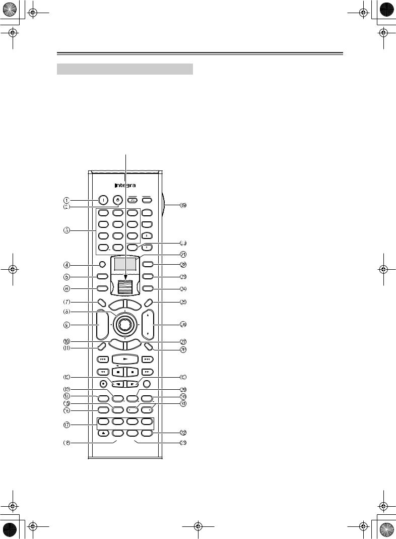
Index Parts and Facilities—Continued
Remote Controller (Amp Mode)
The DTR-10.5’s remote controller is a multipurpose device that can be used to control not just the DTR-10.5 but your other AV components as well. This section explains how its various operating modes can be used to control the DTR-10.5. When you use the Net-Tune mode, see page 74 for details. See page 124-135 for information on using the remote controller to control Integra components connected via  and TVs, VCRs, and AV components made by other manufacturers.
Scroll wheel
On Standby |
TV |
|
|
I |
Input |
1 |
|
|
2 |
|
|
|
|
3 |
|
+ |
|
@.-'/ |
|
|
ABC |
|
|
DEF |
TV CH |
||||
4 |
|
|
5 |
|
|
|
|
6 |
|
- |
|
GHI |
|
|
JKL |
|
|
MNO |
|
||||
7 |
|
|
8 |
|
|
|
|
9 |
|
|
|
PQRS |
|
|
TUV |
|
|
WXYZ |
TV VOL |
||||
+10 |
|
|
0 |
|
|
Clear |
|
||||
--/--- |
|
|
|
|
|
|
|
|
|
# |
|
|
|
|
|
|
|
Direct Tuning |
|||||
Custom |
|
|
|
|
|
|
|
|
|
|
|
|
|
|
|
|
|
|
|
|
|
|
Zone 3 |
Macro |
|
|
|
|
|
|
|
|
|
|
Zone 2 |
Mode |
|
|
|
|
|
|
|
|
|
|
Input |
Dimmer |
|
|
|
|
|
|
|
|
|
|
Sleep |
|
|
|
|
|
u |
|
M |
|
|
||
TV |
|
|
en |
|
|
|
|
||||
|
|
M |
|
|
|
|
|
e |
n |
|
|
|
|
p |
|
|
|
|
|
|
|
||
Input |
o |
|
|
|
|
|
|
u |
|
||
T |
|
|
|
|
r |
A |
u |
|
|
|
|
|
|
|
|
|
|
|
|
|
|||
|
|
|
|
ve |
|
di |
|
|
|||
|
|
|
r |
|
|
|
|
|
|
||
+ |
|
|
e |
|
|
|
|
|
o |
|
|
|
|
S |
|
|
|
|
|
|
A |
|
|
|
|
|
|
|
|
|
|
|
J |
||
|
|
|
|
|
|
|
|
|
|
D |
|
CH |
|
|
|
|
|
Enter |
|
|
|
VOL |
|
Disc |
|
|
|
|
|
|
|
|
|
|
|
- |
|
|
E |
|
|
|
|
|
e |
|
|
|
|
|
xit |
|
|
|
|
||||
|
|
|
|
|
|
id |
|
||||
Prev |
|
|
|
|
Gu |
|
|
||||
R |
et |
|
|
|
|
|
|
p |
|
||
CH |
|
|
|
|
|
|
|
tu |
|
||
|
|
urn |
|
|
Se |
|
|
||||
Display |
|
|
|
|
|
|
|
|
|
|
Muting |
Rec |
Main A |
Main B |
Random |
||||||||
Audio |
Subtitle |
Angle |
Last Memory |
||||||||
Surround |
|
|
THX |
|
|
All CH ST |
Stereo |
||||
Repeat |
|
|
A-B |
|
|
Search |
Memory |
||||
Pure A |
|
Direct |
|
|
DSP |
DSP |
|||||
Repeat |
|
Video |
Music |
Photo |
|||||||
Test Tone |
|
CH SEL |
Level - |
Level + |
|||||||
Playlist |
|
Album |
Artist |
Genre |
|||||||
|
|
Audio SEL |
L Night |
Re-EQ |
|||||||
Caps |
|
Delete |
Language |
Location |
|||||||
RC-556M
Amp mode is used to control the DTR-10.5. To select
Amp mode, press the scroll wheel. “AMP” appears on the display.
Note:
While neither the [Input] button nor the [Mode] button is illuminated, rolling the scroll wheel changes the input source and remote controller mode simultaneously.
1On button
This button is used to turn on the DTR-10.5.
2Standby button
This button is used to set the DTR-10.5 to Standby.
3Number/letter buttons
These buttons are used to enter numbers and letters.
4Custom button
This button is used to access various settings that you can use to customize the operation of the remote controller.
5Macro button
This button is used with the Macro function.
6Mode button
This button is used with the scroll wheel to select the remote controller modes.
7Dimmer button
This button is used to adjust the display brightness.
8Up/Down/Left/Right [ ]/[
]/[ ]/[
]/[ ]/[
]/[ ] & Enter buttons
These buttons are used to select items on the onscreen setup menus (OSD). The [Enter] button is also used to enter names and to confirm settings.
9CH +/– button
This button is used to select radio presets.
0Return button
This button is used to return to the previously displayed onscreen setup menu (OSD).
ADisplay button
This button is used to display various information about the currently selected input source.
BMain A button
For the speakers used in main room A, every press of this button toggles the status between enabled and disabled.
CTHX button
This button is used to select the THX listening modes.
DSurround button
This button is used to select the Dolby and DTS listening modes.
18

Index Parts and Facilities—Continued
EDirect button
This button is used to select the Direct listening mode.
FPure A button
This button is used to select the Pure Audio listening mode.
GTest Tone, CH SEL, Level– & Level+ buttons
These buttons are used to adjust the level of each speaker individually. These functions can be set only with the remote controller. The [Level–] and [Level+] buttons are also used to adjust the volume in Zone 2 or Zone 3.
HAudio SEL button
This button is used to select the audio input signal format (e.g., analog, digital, etc.).
ILIGHT button
This button is used to turn on or off the remote controller’s illuminated buttons.
J Direct Tuning button
SMain B button
For the speakers used in main room B, every press of this button toggles the status between enabled and disabled.
TAll CH ST button
This button is used to select the All Ch Stereo listening mode.
UStereo button
This button is used to select the Stereo listening mode.
V DSP/DSP
  buttons
These buttons are used to select the listening modes.
WRe-EQ button
This button is used to turn on and off the Re-EQ function.
XL Night button
This button is used to set the Late Night function.
This button is used with the number buttons to select a radio station by entering its frequency. Press this button first, and then use the number buttons to enter the frequency.
KDisplay
The top line of this LCD display shows the name of the currently selected input source. The bottom line shows the currently selected remote controller mode.
LZone 3 button
This button is used when you want to set the volume and input source for Zone 3.
MZone 2 button
This button is used when you want to set the volume and input source for Zone 2.
NInput button
This button is used to select the input source. Press this button first, and then roll the scroll wheel until the name of the input source appears on the display.
OSleep button
This button is used to set the Sleep function. This function can be set only with the remote controller.
PVOL 
 button
This button is used to set the volume of the DTR-10.5.
QSetup button
This button is used to access the onscreen setup menus (OSD) that appear on the TV.
RMuting button
This button is used to mute the DTR-10.5. This function can be set only with the remote controller.
Getting Started
19
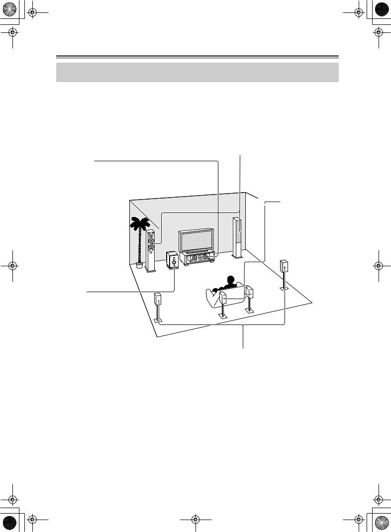
Speaker Placement
Basic Speaker Placements for Home Theater and the Function of Respective Speakers
The DTR-10.5 has many excellent features to recreate a clear three-dimensional sound image and lively sound movement. This enables you to enjoy, at home, the rich sound effects of a live theater or concert hall performance.
When playing a DVD, you can enjoy sound effects provided by DTS or Dolby Digital, depending on the recording format. In addition, you can enjoy THX sound and Integra’s proprietary DSP surround playback for TV or digital satellite broadcasts.
Front left and right speakers
Outputs overall sound. They play the most important role in a home theater system, by creating basic sound images and fields.
Center speaker
Complements the sound effects from front left and right speakers to enrich and clear the sound image and movement. In movies, an actor’s speech comes mainly from the center speaker.
Subwoofer
Outputs only bass sounds to enhance and complement bass sound effects.
Surround back speakers
Enhances the sound space representation with surround channel signals. Recreating sound movement effects and sound fields behind the listener gives a more realistic experience.
Surround left and right speakers
Enhances the sensation of being at a live performance by giving three-dimensional sound movement to the sound effects.
•For optimum surround playback, set the distance between the listener and the speakers so that the time it takes the sound to reach the listener is same. Also, you need to set each speaker volume level individually in order to balance the volume level between speakers (See pages 88 and 90).
20
Speaker Placement—Continued
Placing the Speakers
To fully enjoy surround sound, the configuration and placement of the speakers used are important. Be sure to read through the descriptions in the previous page and shown below.
This section provides examples and descriptions that assume a typical situation.
Front Left and Right Speakers, and Center Speaker
• Place the front left and right speakers symmetrically and so |
|
|
|
|
|
|
|
|
|
|
|
that the distance from the listening position is the same. |
|
|
|
|
|
• When placing speakers, direct the speakers toward the |
|
|
|||
TV or screen |
|
||||
position of the listener’s ears where the listener sits to enjoy Front |
|
|
|
Front |
|
|
Left |
|
Center |
|
Right |
music or movies. |
|
|
|
|
|
• Place the three speakers so that the heights of the three |
|
|
|
|
|
speakers are aligned. The ideal height for the speakers is the |
|
|
|
|
|
height of the listener’s ears. When placing the center |
|
|
|
|
|
speaker above or below the TV, tilt it toward the listener’s |
|
|
|
|
|
ears. |
|
|
|
|
|
•Place the center speaker as close to the screen or monitor as possible and in the center between the left and right front
speakers. When placing the center speaker near the TV, use a shielded speaker.
•If no center speaker is used, place the left and right front speakers closer to each other.
TV |
Left and Right Surround Speakers
•Place these speakers on each side of, or angled behind, the listener.
•Place the surround speakers symmetrically from the listener position and so that the distance from the listener is equal
|
between left and right surround speakers. |
|
|
|
|
|
|
|
• |
When enjoying mainly movies, placing the surround |
|
|
|
|
|
|
|
|
speakers about 3 feet (1 m) higher than the height of the |
|
|
|
|
|
|
|
|
listener’s ears, results in more of a surround effect. |
|
|
|
|
|
|
|
• |
When enjoying mainly music, placing the surround |
|
|
|
|
|
|
|
|
speakers at the height of the front speakers may provide a |
|
Surround Back |
|
|
|
||
|
|
|
|
|
||||
|
|
|
|
|
||||
|
better surround effect. |
|
|
|
|
|
|
|
•When using surround back speakers in addition to the
surround speakers, placing the surround speakers slightly forward from their current position will make the sound movement smoother.
Surround Back Speakers
•Place the speakers about 3 feet (1 m) or higher than the height of the listener’s ears.
•When using one surround back speaker, place it behind the listener.
• When using two surround back speakers, place them behind the listener so that the angles between the lines from each surround back speaker to the listener and a line straight back from the listener are about 30 degrees, forming an equilateral triangle of the listener and the two surround back speakers.
*When using a THX-certified speaker system, also refer to “Speaker Placement Suitable for THX Audio” on the next page.
Installation and Connections
21
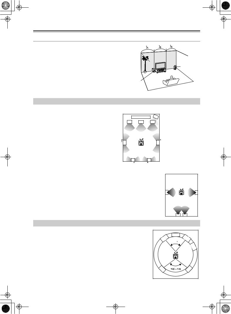
Speaker Placement—Continued
Subwoofer
Using a subwoofer greatly improves the volume level and sound quality of bass sounds. The subwoofer effect depends not only on the listening position but also on the shape of the listening room.
•In general, place the subwoofer in a corner of the room or at a point 1/3 the width of the room.
•Play a movie or music that contains high quality bass sounds to determine the subwoofer placement. Change the subwoofer’s position and check the effect, then select the position where the bass sounds are best heard.
•You can place two subwoofers for more powerful and richer heavy bass sounds.
Corner
1/3 room length
Speaker Placement Suitable for THX Audio
To enjoy sources using THX Cinema or THX Surround EX technology, we recommend using a THX speaker system from THX Ltd. A speaker system supporting the THX Ultra2 standard is best suited for THX Ultra2 Cinema or THX Music Mode.
The layout example on the right represents a case using the dipole speakers. A dipole speaker is a two-way directivity speaker that outputs the same sound in two directions such as forward and backward.
Most dipole speakers are marked with an arrow indicating how they should be oriented in the room in order to match their phases*. Dipole surround speakers should be placed so that their arrows point forward toward the screen, and dipole surround back speakers should be placed so that their arrows point toward each other.
Layout with dipole speakers |
|
|||
|
1 |
2 |
1 |
TV or screen |
|
2 |
Subwoofer |
||
3 |
4 |
5 |
3 |
Front left speaker |
|
|
|
4 |
Center speaker |
|
|
|
5 |
Front right speaker |
|
|
|
6 |
Surround left speaker |
|
|
|
7 |
Surround right |
6 |
|
|
7 |
speaker |
|
|
Surround back left |
||
|
10 |
|
8 |
|
|
|
|
speaker |
|
|
|
|
|
|
|
|
|
9 |
Surround back right |
|
8 |
9 |
|
speaker |
|
10 |
Listening position |
||
|
|
|
||
*Phase: The word represents the waveform position in one cycle (0 to 360 degrees) of a sine wave. If the phase does not match between multiple waveforms due to the distance between multiple speakers, the speaker orientation, or the miswiring of positive and negative poles, the sound image or space may be obscured or the sound may be less easy to listen to.
When playing the source in the THX Ultra2 Cinema or THX Music Mode format using two |
|
|
|
|
|
|
|
|
6 |
|
|
|
|
|
|
7 |
|
surround back speakers supporting the THX Ultra2 standard, place them as close together as |
|
|
|
|
|
|
||
|
|
|
10 |
|
|
|
||
|
|
|
|
|
|
|||
possible. After placing the surround back speakers, perform the settings described in the |
|
|
|
|
|
|
||
|
|
As close as |
||||||
“THX Audio Setup” (page 91). |
|
|
||||||
|
|
possible |
||||||
|
|
|
|
|
|
|
|
|
|
|
8 |
|
9 |
|
|
||
Speaker Placement Suitable for a Music Source such as DVD-Audio
This placement is based on the ITU-R* recommendation. In this placement, five speakers with the same performance capabilities are used for front left and right, center, and left and right surround speakers, and they are placed so that the distances between every speaker and the listening position are equal to each other and the heights of the speaker and the listener’s ears are the same. A mixing studio used for making multichannel DVD-Audio source material adopts this placement.
*ITU-R: International Telecommunication Union Radiocommunication Sector
|
Center |
Front |
Front |
Left |
Right |
|
60 |
|
Sub- |
|
woofer |
SL |
SR |
22
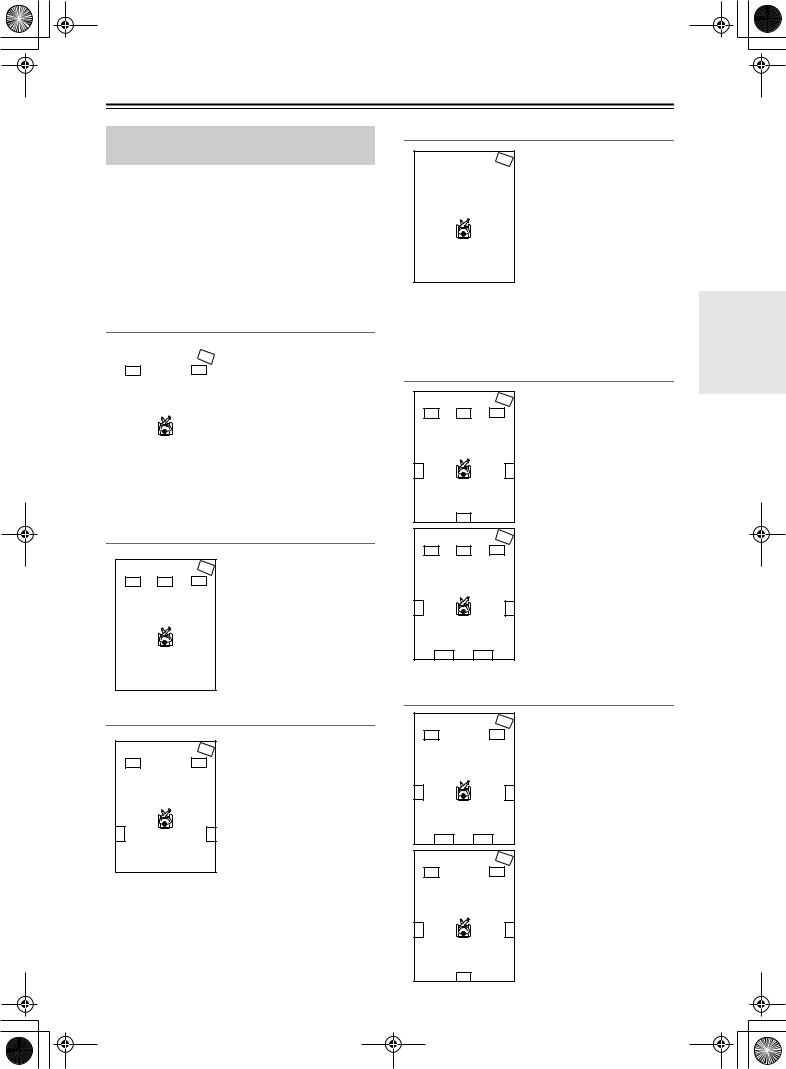
Speaker Placement—Continued
Available Speaker Placements According to the Number of Speakers
The following speaker placements will be available according to the number of speakers connected to the DTR-10.5. For the number of speaker channel, _.1 ch represents a subwoofer.
Key to abbreviations:
FL: Front left speaker, FR: Front right speaker, C: Center speaker, SL: Surround left speaker, SR: Surround right speaker, SBL: Surround back left speaker, SBR: Surround back right speaker, SW: Subwoofer
2 ch/2.1 ch
|
|
This placement is used with |
|
SW |
two speakers (front left and |
FL |
FR |
right speakers). It is |
|
|
optimum for 2 ch sources |
|
|
including analog 2 ch, 2 ch |
|
|
linear PCM, Dolby Digital, |
|
|
DTS, DTS96/24, and AAC |
|
|
format sources. When the |
|
|
number of channels in the |
|
|
source is 3.1 or greater, the |
|
|
|
|
|
signals will be distributed |
through the left and right channels accordingly.
3 ch/3.1 ch
SW
FL C FR
This placement is used with three speakers (front left, front right, and center speakers). When the number of channels in the source is 4.1 or greater, the signal for surround and surround back channels will be output through the front left and right speakers.
4 ch/4.1 ch
FL
SL
SW
FR
SR
In this placement, when the number of channels in the source is 5.1 or greater, the center channel signal will be output through the front left and right speakers, and the surround back channels will be output through the surround speakers.
5 ch/5.1 ch
This placement is suitable for
|
|
|
|
|
|
SW |
playing 5.1 ch sources |
|
|
|
FL |
|
C |
|
FR |
|
|
|
|
|
|
|
including analog multichannel, |
|||
|
|
|
|
|
|
|
|
|
|
|
|
|
|
|
|
|
Dolby Digital, DTS, and AAC |
|
|
|
|
|
|
|
|
format sources. When the |
|
|
|
|
|
|
|
|
source is 2 ch or mono, the |
|
|
|
|
|
|
|
|
signal will be decoded with |
|
SL |
|
|
|
|
|
SR |
|
|
|
|
|
|
|
Dolby Pro Logic II or DTS |
||
|
|
|
|
|
|
|
|
|
|
|
|
|
|
|
|
|
NEO:6 format and played as |
|
|
|
|
|
|
|
|
5.1 ch sources. |
When the number of channels in the source is 6.1 or |
||||||||
greater, the surround back signal will be distributed |
||||||||
through the surround left and right speakers |
||||||||
accordingly. |
|
|
|
|||||
6 ch/6.1 ch/7 ch/7.1 ch (with center speaker)
SW
FL C FR
SL |
SR |
SB
SW
FL C FR
SL |
SR |
This placement is suitable for playing 6.1 ch sources including DTS-ES Matrix/ Discrete and Dolby Surround EX format signals.
When you use two surround back speakers, the same signal will be output from them because the surround back channel is mono. When the source is 2 ch or mono, it will be decoded with the Dolby Pro Logic IIx/DTS NEO:6 format and played as 6.1/7.1 ch sources.
Installation and Connections
SBL SBR
6 ch/6.1 ch/5 ch/5.1 ch (without center speaker)
FL
SL
SBL
FL
SW
FR
SR
SBR
SW
FR
This placement is suitable for playing 5.1 or 6.1 ch sources when the surround back sound is much more preferred than the center sound with less speaker units than the normal configuration. The center channel signal will be output through the front left and right speakers.
SL |
SR |
|
SB |
23
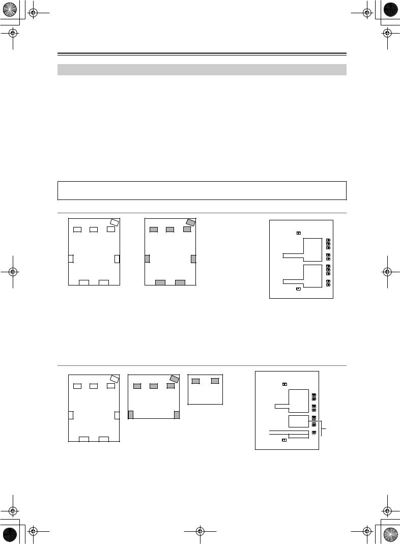
Speaker Placement—Continued
Connection Examples
The DTR-10.5 has two speaker terminal blocks for speaker system [A] and [B]. This allows you to build two 7.1 ch home theater systems, and various speaker placements and connections are also available. For example, some channels of either speaker system can be used for another room (Zone 2), or you can select one of two speaker systems for playback according to the source.
When you use two speaker systems, you have to associate the speakers with the zone (e.g., Main A, Main B, etc.). After making the association, for example, pressing the “MAIN A” button on the remote controller will output the source from the speakers configured as “Main A.”
Here are some examples of speaker placement and zone association. These examples can be your reference when you build your own home theater system. The illustration on the right represents the actual settings displayed corresponding to each example. For details on configuring speaker placement and zone association, see page 88.
*In the following illustrations, white speakers denote speaker system [A] and gray ones denote speaker system [B]. *Key to abbreviations:
FL: Front left speaker; FR: Front right speaker; C: Center speaker; SL: Surround left speaker; SR: Surround right speaker; SBL: Surround back left speaker; SBR: Surround back right speaker; SW: Subwoofer
When you wish to configure 7.1 ch speaker system in the main room A only, the initial setting can be used without any modification.
Main room A: 7.1 ch speaker system; Main room B: 7.1ch speaker system
|
|
SW |
|
|
SW |
1-1.Speaker Config |
|
|
|
FR |
|
|
FR |
||
FL |
C |
FL |
C |
===================== |
|||
|
|
|
|
|
|
Speaker A |
|
|
|
|
|
|
|
a.Front L/R |
:Main A |
Main room A |
Main room B |
b.Center |
:Main A |
||||
c.Surr L/R |
:Main A |
||||||
|
|
|
|
|
|
d.Surr Back |
|
SL |
|
SR |
SL |
|
SR |
:Main A |
2ch |
|
|
e.Subwoofer |
:Main A |
||||
|
|
|
|
|
|
Speaker B |
|
|
|
|
|
|
|
f.Front L/R |
:Main B |
|
|
|
|
|
|
g.Center |
:Main B |
|
|
|
|
|
|
h.Surr L/R |
:Main B |
|
|
|
|
|
|
i.Surr Back |
|
|
SBL |
SBR |
|
SBL |
SBR |
:Main B |
2ch |
|
|
|
|
|
|
j.Subwoofer |
:Main B |
•Set all the zone parameters for speaker system [A] to “Main A.”
•Set all the zone parameters for speaker system [B] to “Main B.”
•Pressing the [Main A] or [Main B] button causes the sound to be output from the speaker system associated with the zone button. Both speaker systems
cannot be selected simultaneously.
*If you set all the zone parameters for speaker system [B] to “Main A” and play a single source, the same audio signal will be output from both speaker systems [A] and [B].
Main room A: 7.1 ch speaker system; Main room B: 5.1 ch speaker system; Sub room (Zone 2): 2 ch
speakers |
|
|
|
|
|
SW |
|
FL |
C |
FR |
|
Main room A |
|
||
SL |
|
SR |
SL |
SBL |
|
SBR |
|
SW |
FL |
FR |
|
FL C FR
Zone 2
Main room B
SR
Powered
Zone 2
1-1.Speaker Config |
|
===================== |
|
Speaker A |
|
a.Front L/R |
:Main A |
b.Center |
:Main A |
c.Surr L/R |
:Main A |
d.Surr Back |
|
:Main |
A 2ch |
e.Subwoofer |
:Main A |
Speaker B |
|
f.Front L/R |
:Main B |
g.Center |
:Main B |
h.Surr L/R |
:Main B |
i.Surr Back |
Main B |

 :Powered Zone 2
j.Subwoofer :Main B 
•Set all the zone parameters for speaker system [A] to “Main A.” Set the zone parameters for speaker system [B] to “Main B” and “Zone 2” accordingly.
•Both main room A and B cannot be used simultaneously. However, while either of the main rooms is used, you can enjoy a different source in Zone 2.
•Note that when you use Zone 2, the surround back speakers for main room A cannot be used since Zone 2 uses the surround back speaker circuit for main room A.
24
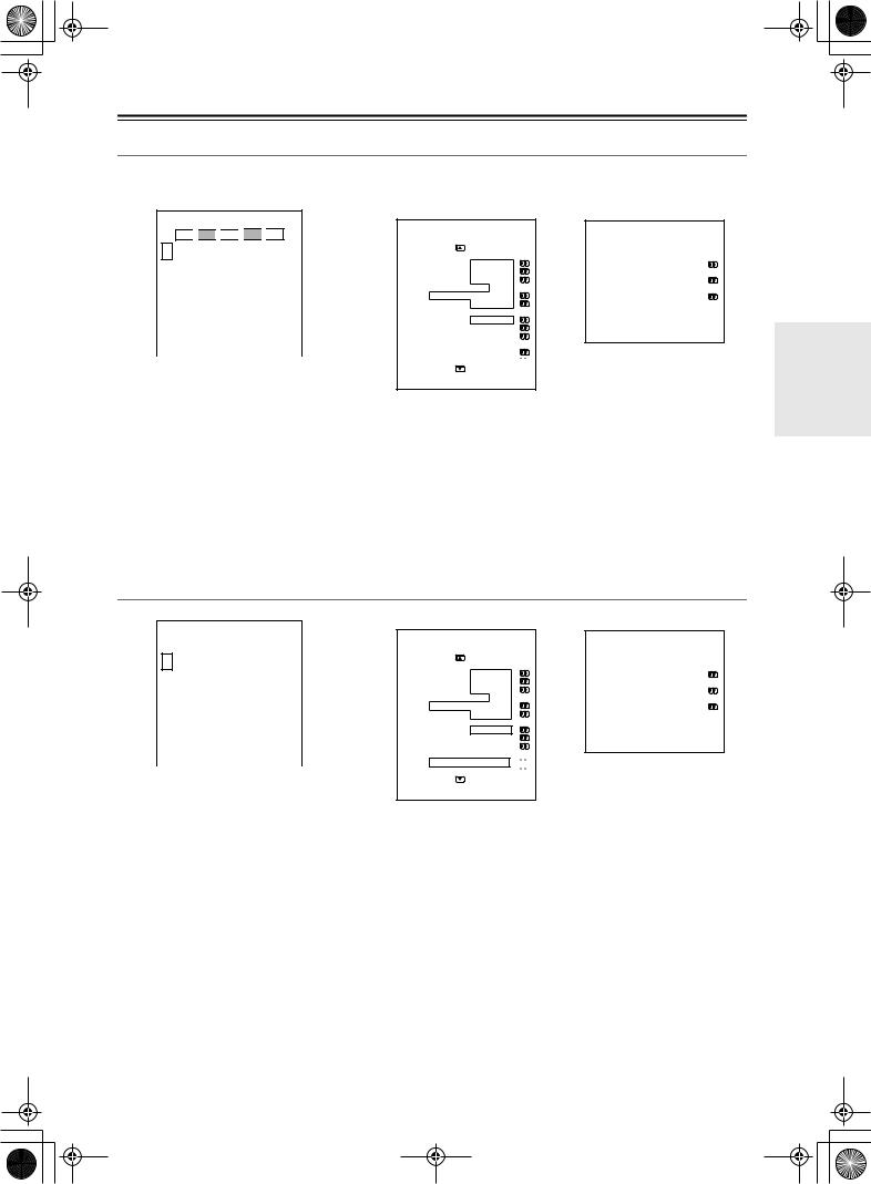
Speaker Placement—Continued
Main room A: 7.1 ch speaker systems and the two additional front speakers
(When you want to use speaker system [A] for movies and enjoy 7.1 surround sound and the two additional front
speakers for classic music.)
FL 
 FL
FL 
 C
C 
 FR
FR 
 FR
FR
SW
Main room A
SL |
|
|
|
|
|
SR |
|
|
|
|
|
|
|
|
|
SBL |
|
SBR |
|
|
1-1.Speaker Config
=====================
Speaker A
a.Front L/R |
:Main A |
b.Center |
:Main A |
c.Surr L/R |
:Main A |
d.Surr Back |
|
:Main A |
2ch |
e.Subwoofer |
:Main A |
Speaker B |
|
f.Front L/R |
:Main A |
g.Center |
:Not Used |
h.Surr L/R |
:Not Used |
i.Surr Back :Not Used
j.Subwoofer :Not Used

3-3.Stereo
=====================
a. Re-EQ/Academy :Off
b.Front Speaker: B
c.Subwoofer: A
Here is an example of the stereo listening mode.
•Set all the zone parameters for speaker system [A] to “Main A.”
•Set the front speaker parameters for speaker system [B] to “Main A.”
•If you want to use the front speakers of speaker system [B] for specific sources, select the source and set the front speaker setting parameters to “B” in the listening mode setup menu.
When you want to output to both speaker systems simultaneously, you can choose the “A+B” setting unless any of the speakers has an impedance of 8 ohm or lower.
•To output the sound, press the [Main A] button on the remote controller.
Main room A: 7.1 ch speaker system and the two additional front speakers connected through the BTL or bi-amp connection (when you want to use either the 7.1 ch speakers or the additional front speakers according to the source)
|
|
FL |
|
FL |
|
C |
|
FR |
|
FR |
|
|
|
|
|
|
|
|
|
||
SW |
|
|
|
|
|
|
|
|
|
|
Main room A
SL |
|
|
|
|
|
SR |
|
|
|
|
|
|
|
|
|
SBL |
|
SBR |
|
|
1-1.Speaker Config
=====================
Speaker A
a.Front L/R |
:Main A |
b.Center |
:Main A |
c.Surr L/R |
:Main A |
d.Surr Back |
|
:Main A |
2ch |
e.Subwoofer |
:Main A |
Speaker B |
|
f.Front L/R |
:Main A |
g.Center |
:Not Used |
h.Surr L/R |
:Not Used |
i.Surr Back
:BTL for Front 
 j.Subwoofer :Not Used

3-3.Stereo
=====================
a. Re-EQ/Academy :Off
b.Front Speaker: B
c.Subwoofer: A
Here is an example of the stereo listening mode.
•Set all the zone parameters for speaker system [A] to “Main A.”
•For speaker system [B], set the front speaker parameters to “Main A” and the surround back speaker parameters to “BTL for Front ” or “Bi-Amp for Front” (For details on connections, see page 29).
•When you want to use the front speakers of speaker system [B] for specific sources, select the source and set the
front speaker parameters to “B” in the listening mode setup menu.
*When using the BTL or bi-amp connections, the two speaker systems cannot be used to output simultaneously due to the speaker impedance limitation.
Installation and Connections
25
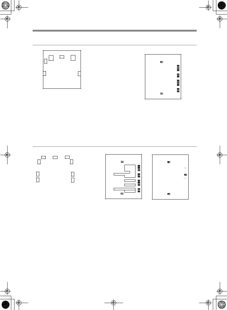
Speaker Placement—Continued
Main room A: 5.1 ch speaker system including the front speakers connected through the BTL or biamp connections
FL |
C |
FR |
|
SW
Main room A
SL
SR
1-1.Speaker Config
=====================
Speaker A
a.Front L/R |
:Main A |
||
b.Center |
:Main A |
||
c.Surr L/R |
:Main A |
||
d.Surr Back |
|
|
|
|
:BTL for Front |
|
|
e.Subwoofer |
:Main A |
|
|
|
Speaker |
B |
|
f.Front L/R |
:Not Used |
||
g.Center |
:Not Used |
||
h.Surr L/R |
:Not Used |
||
i.Surr Back |
|
|
|
:Not Used |
|||
j.Subwoofer |
:Not Used |
||
•For speaker system [A], set the surround back speaker parameters to “BTL for Front ” or “Bi-Amp for Front” and all the other speaker parameters to “Main A” (For details on speaker connections, see page 29).
•For speaker system [B], set the speaker parameters to “Not Used.”
*When using the BTL or bi-amp connections, you cannot use Zone 2 since the surround back channel is used for the front speakers of main room A.
Main room A: 7.1 ch from speaker system [A] and additional subwoofer and surround speakers from speaker system [B] (suitable for enjoying more powerful and lively surround sound in main room A); Main room B: two front speakers from speaker system [B] using the BTL or bi-amp connections
|
|
|
|
|
|
|
|
|
|
|
|
|
|
|
|
|
|
|
|
|
|
|
|
|
|
|
|
|
|
|
|
|
|
|
|
|
|
|
|
|
|
FL |
|
FR |
|
|
|
|
|
FL |
|
|
|
C |
|
|
|
FR |
|
|
|
|
|
|||||
|
|
|
|
|
|
|
|
|
|
|
|
|
|
|
|
|
|
|
|
|
|
|
|
|
|
|
|
|
|
|
|
|
|
|
|
|
|
|
|
|
|
|
|
|
|
|
SW |
|
|
|
|
|
|
|
|
|
|
|
SW |
|
|
Main room B |
||||||
|
|
|
|
|
Main room A |
|
||||||||||||||||
|
|
|
|
|
|
|
|
|
|
|
||||||||||||
|
|
|
|
|
|
|
|
|
|
|||||||||||||
|
|
|
|
|
|
|
|
|
|
|
|
|
|
|
|
|
|
|
|
|||
|
|
|
|
|
|
|
|
|
|
|
|
|
|
|
|
|
|
|
|
|
||
SL |
|
|
|
|
|
|
|
|
|
|
|
|
|
SR |
|
|
|
|
|
|
||
|
|
|
|
|
|
|
|
|
|
|
|
|
|
|
|
|
|
|
|
|
||
|
|
|
|
|
|
|
|
|
|
|
|
|
|
|
|
|
|
|||||
SL |
|
|
|
|
|
|
|
|
|
|
|
|
|
SR |
|
|
|
|
|
|
||
|
|
|
|
|
|
|
|
|
|
|
|
|
|
|
|
|
|
|
|
|
|
|
|
|
|
|
|
|
|
SBL |
|
|
SBR |
|
|
|
|
|
|
|
|
|
|||
1-1.Speaker Config
=====================
Speaker A
a.Front L/R |
:Main A |
b.Center |
:Main A |
c.Surr L/R |
:Main A |
d.Surr Back |
|
:Main A |
2ch |
e.Subwoofer |
:Main A |
Speaker B |
|
f.Front L/R |
:Main B |
g.Center |
:Not Used |
h.Surr L/R |
:Main A |
i.Surr Back
:BTL for Front j.Subwoofer :Main A
3-5.Multichannel Input
=====================
b.Re-EQ :Off

e.Surr L/R Sp |
:A+B |
g.Subwoofer :A+B

Here is an example of the multichannel listening mode.
•For speaker system [A], set all the speaker parameters to “Main A.”
•For speaker system [B], set the surround speaker and subwoofer parameters to “Main A,” the front speaker parameters to “Main B,” and the surround back speaker parameters to “BTL for Front” or “Bi-Amp for Front” (For details on speaker connection, see page 29).
•When you want to use the surround speakers and subwoofer of speaker system [B] for specific sources, select the source and set the parameters for these speakers to “B” or “A+B” in the listening mode setup menu.
When you set the parameter to “B,” the audio signal comes out from the surround speakers and subwoofer of speaker system [B]. When you set the parameter to “A+B,” the signal comes out from the surround speakers and subwoofer of both speaker systems [A] and [B].
26
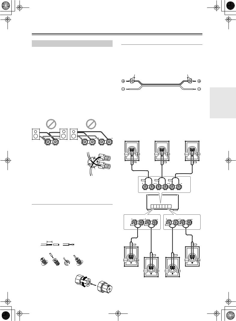
Connecting Speakers
Connecting to the Speaker Terminals
After determining the layout of your speaker system, it is now necessary to connect the speakers correctly to your DTR-10.5.
For the USA and Canadian models, you can also use banana plugs/connectors.
You can connect speakers with an impedance of between 4 and 16 ohms. If the impedance of any of the connected speakers is 4 ohms or more, but less than 6 ohms, be sure to set the Speaker Impedance to “4 ohms” (see page 89). If you use speakers with a lower impedance, and use the amplifier at high volume levels for a long period of time, the built-in protection circuit may be activated.
Notes:
•Even if you are using only one speaker or listening to monaural (mono) sound, never connect a single speaker in parallel to both the right and left channel terminals.
R L
•To prevent circuitry damage, never short-circuit the positive (+) and negative (–) speaker wire.
• Be sure to connect the positive and |
|
negative cables for the speakers |
NO! |
properly. If they are mixed up, the |
|
left and right signals will be |
|
reversed and the audio will sound unnatural. |
|
•Do not connect more than one speaker cable to one speaker terminal. Doing so may damage the DTR-10.5.
Connecting the Speaker Cable
1.Strip away approx. 5/8 inch (15 mm) of the wire insulation.
2.Twist the wire ends tightly together.
3.Unscrew the speaker terminal cap.
4.Insert the exposed wire end.
5.Tighten speaker terminal cap.
1 |
|
2 |
|
5/8" |
|
|
(15 mm) |
|
3 |
4 |
5 |
Tip:
The terminal wrench that comes with this unit is a useful tool for tightening/ loosening the speaker terminal cap.
Attaching the Speaker Labels
The positive speaker terminals on the DTR-10.5 are color coded for easy identification. Attach the supplied speaker labels to the speaker cables, and then match the colors on the speaker cables to the corresponding terminals.
Speaker label |
Speaker label |
The speaker channels are colored as follows:
Front left speaker (+): White |
|
|
Front right speaker (+): Red |
|
|
Center speaker (+): Green |
|
|
Surround left speaker (+): Blue |
|
|
Surround right speaker (+): Grey |
|
|
Surround back left speaker (+): Brown |
||
|
|
andInstallationConnections |
Surround back right speaker (+): Tan |
||
Front right |
Center |
Front left |
speaker |
speaker |
speaker |
FRONT R |
CENTER |
FRONT L |
|
|
SPEAKERS A |
|
|
|
DTR-10.5 |
SURR R |
SURR BACK R (ASSIGNABLE) |
SURR BACK L (ASSIGNABLE) |
SURR L |
|
|
(SINGLE) |
|
SPEAKERS A |
|
|
SPEAKERS A |
Surround |
Surround |
right |
left |
speaker |
speaker |
Surround |
Surround |
back right |
back left |
speaker |
speaker |
27

Connecting Speakers—Continued
Connecting a Subwoofer
Use the SUBWOOFER PRE OUT A/B jack to connect a subwoofer with a built-in power amplifier. If your subwoofer does not have a built-in amplifier, connect an amplifier to the SUBWOOFER PRE OUT A/B jack and the subwoofer to the amplifier.
You can connect two subwoofers for different speaker systems. You have to assign a subwoofer to the room in which it will be used (See page 88).
|
|
OPTICAL |
COAXIAL |
R |
L |
R |
L |
IN |
|
|
|
|
PH |
|
|
|
|
|
|
|
|
R |
L |
|
|
|
|
ETHERNET |
|
|
|
|
|
|
|
|
|
|
|
R |
L |
R |
L |
|
|
PRE OUT A |
SURR R |
SURR BACK R ASSIGNABLE |
FRONT R |
|
CENTER |
|
FRONT L |
L |
A |
|
|
|
|
|
|
|
R |
|
|
|
|
|
|
|
|
|
B |
|
|
|
|
|
|
|
|
|
|
FRONT R (BTL) |
|
|
|
|
FRONT L |
|
PRE |
|
|
|
|
|
|
|
|
OUT B |
|
|
|
|
|
|
|
LINE INPUT |
|
|
|
|
|
|
|
|
|
SUB |
SUB |
|
|
|
|
|
|
|
WOOFER |
WOOFER |
|
|
|
|
|
|
|
PRE |
PRE |
|
|
|
|
|
|
|
OUT A |
OUT B |
|
|
|
|
|
|
Connecting Auxiliary Power Amplifier (For Speaker System [A] only)
These jacks are for connecting an auxiliary power amplifier. The PRE OUT terminals on the DTR-10.5 use the mode settings for speaker system [A].
You can use an auxiliary power amplifier to listen at louder volumes than you can with the DTR-10.5 alone. When using a power amplifier, connect each speaker to the power amplifier.
DTR-10.5
to White
|
L |
PRE OUT A |
to Brown |
|
|
|
FRONT |
SURR SURR |
|
|
|
|
BACK |
L |
|
|
|
|
|
|
|
L |
|
|
|
R |
R |
|
|
|
to Red |
|
|
R |
|
|
|
|
to Tan |
|
|
CENTER |
|
|
|
|
to Blue |
to Gray |
|
|
to Green |
L |
R |
|
|
|
|
|
|
Front |
Center |
|
Surround |
Surround back |
R  L R
L R  L R
L R  L
L
INPUT |
INPUT |
INPUT |
INPUT |
R L |
|
R L |
R L |
Power amplifier
|
|
|
|
|
|
|
|
|
|
|
|
|
|
|
|
|
|
|
|
|
|
|
|
|
|
|
|
|
|
|
|
|
|
|
|
|
|
|
|
|
|
|
|
|
|
|
|
|
|
|
|
1 |
|
2 |
|
|
3 |
|
|
4 |
|
5 |
|
6 |
|
7 |
|
|||||||
|
|
|
|
|
|
|
|
|
|
|
|
|
|
|
|
|
|
|
|
|
|
|
|
|
1. |
Front left speaker |
|
|
|
6. |
|
Surround back left |
|||||||||||||||||
2. |
Front right speaker |
|
|
|
|
|
|
speaker |
||||||||||||||||
3. |
Center speaker |
|
|
|
|
|
|
|
7. |
|
Surround back right |
|||||||||||||
4. |
Surround left |
|
|
|
|
|
|
|
|
|
|
speaker |
||||||||||||
|
speaker |
|
|
|
|
|
|
|
|
|
|
|
|
|
|
|
|
|
|
|
|
|||
5.Surround right speaker
28
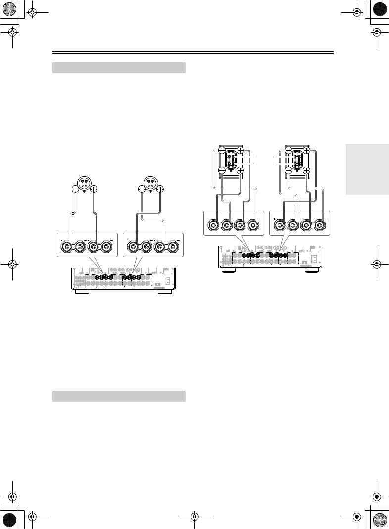
Connecting Speakers—Continued
Using the BTL Connection
To get more powerful sound output, you can make the BTL (Bridged Transless) connection using the front and surround back speaker terminals on the DTR-10.5. In this connection, two speaker outputs of the stereo amplifier will be used as mono output by combining the individual stereo channel outputs, allowing you to get about twice the output.
Note:
When using the BTL connection, make sure that the speaker impedance is 8 ohm or higher.
For the settings on the BTL connection, see page 88.
Right speaker |
Left speaker |
||||||||||
|
|
|
|
|
|
|
|
|
|
|
|
|
|
|
|
|
|
|
|
|
|
|
|
|
|
|
|
|
|
|
|
|
|
|
|
|
|
|
|
|
|
|
|
|
|
|
|
Caution:
•When making the bi-amp connection, make sure to remove the shorting bars connecting the high range (Tweeter) and low range (Woofer) terminals.
•When using the bi-amp connection, make sure that the speaker impedance is 8 ohm or higher.
For the settings on the bi-amp connection, see pages 88, 89.
Bi-wiring-enabled speakers
Right speaker |
Left speaker |
High range (Tweeter)
Low range (Woofer)
SURR BACK R (ASSIGNABLE) |
FRONT R |
FRONT L |
SURR BACK L (ASSIGNABLE) |
|
|
|
(SINGLE) |
SURR BACK R (ASSIGNABLE) |
FRONT R |
FRONT L |
SURR BACK L (ASSIGNABLE) |
|
|
|
(SINGLE) |
|
|
|
R |
L |
R |
|
|
|
PRE OUT A |
SURR R |
SURR BACK R ASSIGNABLE |
FRONT R |
|
CENTER |
FRONT L |
SURR BACK L ASSIGNABLE |
SURR L |
AC INLET
L |
A |
|
SPEAKERS A |
|
|
|
AC OUTLET |
R |
|
|
|
|
B |
|
SPEAKERS B |
|
FRONT R (BTL) |
FRONT L (BTL) |
|
|
PRE |
UDD |
MODEL NO. DTR-10.5 |
|
OUT B |
In the BTL connection, the (–) L/R speaker terminals on the DTR-10.5 will not be used.
1.Connect the (+) terminal on the right speaker to the FRONT R SPEAKERS (+) terminal on the DTR-10.5 and the (–) terminal on the right speaker to the SURR BACK R SPEAKERS (+) terminal on the DTR-10.5.
2.Connect the (+) terminal on the left speaker to the FRONT L SPEAKERS (+) terminal on the DTR-10.5 and the (–) terminal on the left speaker to the SURR BACK L SPEAKERS (+) terminal on the DTR-10.5.
Using Bi-amp Connection
When you use bi-wiring-enabled speakers for the front speakers, you can make the bi-amp connection. In this connection, the front and surround back speaker terminals will be used for tweeter and woofer, respectively. This connection allows you to obtain high quality sound as well as maximum treble and bass performance from the tweeter and woofer, enriching your sound experience.
|
|
|
R |
L |
R |
|
|
|
PRE OUT A |
SURR R |
SURR BACK R ASSIGNABLE |
FRONT R |
|
CENTER |
FRONT L |
SURR BACK L ASSIGNABLE |
SURR L |
AC INLET
L |
A |
|
SPEAKERS A |
|
|
|
AC OUTLET |
R |
|
|
|
|
B |
|
SPEAKERS B |
|
FRONT R (BTL) |
FRONT L (BTL) |
|
|
PRE |
UDD |
MODEL NO. DTR-10.5 |
|
OUT B |
1.Connect the (+) tweeter terminal of the right speaker to the FRONT R SPEAKERS (+) terminal on the DTR-10.5 and the (+) woofer terminal of the right speaker to the SURR BACK R SPEAKERS (+) terminal on the DTR-10.5.
2.Connect the (–) tweeter terminal of the right speaker to the FRONT R SPEAKERS (–) terminal on the DTR-10.5 and the (–) woofer terminal of the right speaker to the SURR BACK R SPEAKERS (–) terminal on the DTR-10.5.
3.Connect the (+) tweeter terminal of the left speaker to the FRONT L SPEAKERS (+) terminal on the DTR-10.5 and the (+) woofer terminal of the left speaker to the SURR BACK L SPEAKERS (+) terminal on the DTR-10.5.
4.Connect the (–) tweeter terminal of the left speaker to the FRONT L SPEAKERS (–) terminal on the DTR-10.5 and the (–) woofer terminal of the left speaker to the SURR BACK L SPEAKERS (–) terminal on the DTR-10.5.
Installation and Connections
29
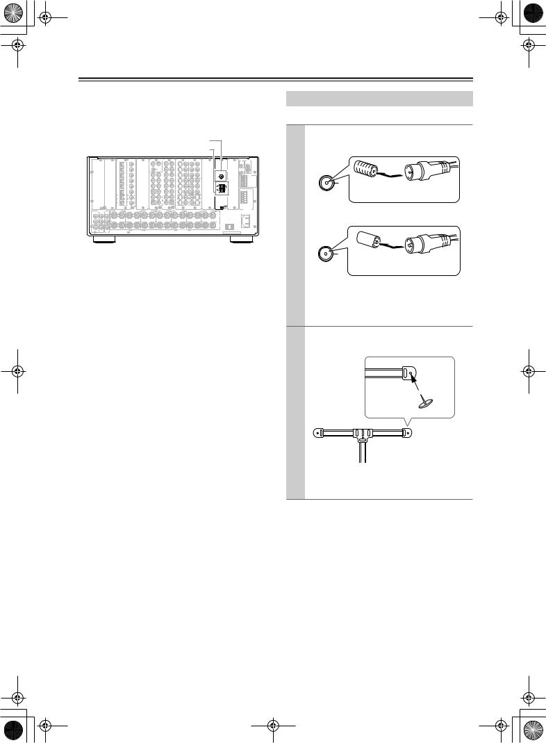
Connecting Antennas
This chapter explains how to connect the supplied indoor FM antenna and AM loop antenna, and how to connect commercially available outdoor FM and AM antennas.
FM antenna connector
AM antenna push terminals
DIGITAL IN |
DIGITAL IN |
|
|
|
AUDIO IN |
|
|
S VIDEO |
VIDEO |
|
|
|
|
|
|
12 V |
RS232 |
OPTICAL |
COAXIAL |
FR |
FL |
R |
L |
R |
L |
IN |
IN |
IN 1 |
IN 2 |
COMPONENT |
VIDEO |
ANTENNA |
HDMI |
||
|
|
|
|
|
|
|
|
|
|
|
|
IN |
TRIGGER |
|
|||
1 |
1 |
|
|
PH |
4 |
|
1 |
|
|
|
|
Y |
|
|
|
OUT |
|
|
|
|
|
|
|
|
|
|
|
Y |
|
IN 1 |
E |
|
|
|
SUB |
|
C |
|
|
|
|
|
|
|
|
|
|
2 |
2 |
|
|
|
5 |
2 |
|
P |
|
|
|
|
|
|
SR |
|
SL |
R |
L |
|
|
P |
|
|
|
“Net-Tune” |
3 |
3 |
|
|
1 |
6 |
3 |
|
P |
|
|
IR IN |
|
trademark of |
|
|
|
|
|
||||||||
Onkyois a |
Corporation. |
|
|
|
|
|
|
|
|
|
FM |
|
|
|
|
|
SBR |
|
SBL |
|
|
|
1 |
IN 3 |
75 |
|
+12V DC PWR SUPPLY |
|
|
|
|
|
|
2 |
7 |
|
|
P |
|
IN 2 |
GND |
|
|
4 |
4 |
|
|
4 |
|
Y |
|
MAIN |
|||
|
|
|
FR |
FL |
|
|
|
|
|
|
|
|
ZONE 2 |
ETHERNET |
5 |
5 |
|
|
3 |
8 |
5 |
|
P |
|
|
ZONE 3 |
|
|
Net-Tune |
|
|
|
|
|
|
||||||
|
|
|
SUB |
|
C |
|
|
|
|
Y |
AM |
|
|
|
|
6 |
6 |
|
|
1 |
9 |
6 |
|
P |
|
|
A |
|
|
|
SR |
|
SL |
|
|
|
|
P |
|
|
B |
|
|
1 |
1 |
|
|
2 |
4 |
1 |
3 |
|
|
|
C |
GND
|
SBR |
SBL |
|
|
|
|
|
|
D |
|
|
3 |
|
5 |
|
|
|
P |
E |
2 |
2 |
|
2 |
|
4 |
|
|||
|
|
R |
L |
R |
L |
|
|
|
|
|
|
|
|
|
S VIDEO |
VIDEO |
VIDEO |
S VIDEO |
|
12V TRIGGER OUT
|
PRE OUT A |
SURR R |
SURR BACK R (ASSIGNABLE) |
FRONT R |
CENTER |
FRONT L |
SURR BACK L (ASSIGNABLE) |
SURR L |
|
|
|
FRONT |
SURR |
SURR |
|
|
|
|
|
SINGLE |
|
|
AC INLET |
BACK |
|
|
|
|
|
|
|
|
|
||
L |
|
|
A |
|
|
|
|
|
|
SPEAKERS A |
|
|
|
|
|
|
|
|
|
|
|
AC OUTLET |
|
|
|
|
|
|
|
|
|
|
|
AC 120V |
60Hz |
R |
|
|
|
|
|
|
|
|
|
SWITCHED |
|
|
|
|
|
|
|
|
|
|
120W 1A MAX. |
||
|
|
|
B |
|
|
|
|
|
|
SPEAKERS B |
|
CENTER |
SUB |
SUB |
|
FRONT R (BTL) |
|
|
FRONT L (BTL) |
|
|
|
|
WOOFER |
WOOFER |
|
|
|
|
|
MODEL NO. DTR-10.5 |
||||
|
|
PRE |
|
|
|
|
|
|
UDD |
||
|
|
OUT B |
|
|
|
|
|
|
|||
Connecting the Indoor FM Antenna
The supplied indoor FM antenna is for indoor use ony.
1 Attach the FM antenna, as shown.
■ USA and Canadian Models
FM
75 Insert the plug fully into the socket.
■ Australian Model
FM
75 Insert the plug fully into the socket
Once your DTR-10.5 is ready for use, you’ll need to tune into an FM radio station and adjust the position of the FM antenna to achieve the best possible reception.
2 Use thumbtacks or something similar to fix the FM antenna into position.
Thumbtacks, etc.
Caution: Be careful that you don’t injure yourself when using thumbtacks.
If you cannot achieve good reception with the supplied indoor FM antenna, try using a commercially available outdoor FM antenna instead.
30
 Loading...