


INSTRUCTION MANUAL
HF TRANSCEIVER
i78
This device complies with Part 15 of the FCC rules. Operation is subject to the following two conditions: (1) This device may not cause harmful interference, and (2) this device must accept any interference received, including interference that may cause undesired operation.

IMPORTANT
READ THIS INSTRUCTION MANUAL CAREFULLY before attempting to operate the transceiver.
SAVE THIS INSTRUCTION MANUAL. This manual contains important safety and operating instructions for the IC-78.
EXPLICIT DEFINITIONS
WORD |
DEFINITION |
|
RWARNING |
Personal injury, fire hazard or electric |
|
|
shock may occur. |
|
CAUTION |
Equipment damage may occur. |
|
|
|
|
NOTE |
Inconvenience only. No risk of per of |
|
personal injury, fire or electric shock. |
||
|
||
|
|
PRECAUTIONS
RWARNING HIGH VOLTAGE! NEVER attach an antenna or internal antenna connector during transmission. This may result in an electric shock or burn.
RNEVER apply AC to the [DC13.8V] jack on the transceiver rear panel. This could cause a fire or ruin the transceiver.
RNEVER apply more than 16 V DC, such as a 24 V battery, to the [DC13.8V] jack on the transceiver rear panel. This could cause a fire or ruin the transceiver.
RNEVER let metal, wire or other objects touch any internal part or connectors on the rear panel of the transceiver. This may result in an electric shock.
NEVER expose the transceiver to rain, snow or any liquids.
AVOID using or placing the transceiver in areas with temperatures below –10°C (+14°F) or above +60°C (+140°F). Be aware that temperatures on a vehicle’s dashboard can exceed 80°C (+176°F), resulting in permanent damage to the transceiver if left there for extended periods.
AVOID placing the transceiver in excessively dusty environments or in direct sunlight.
AVOID placing the transceiver against walls or putting anything on top of the transceiver. This will obstruct heat dissipation.
During mobile operation, DO NOT operate the transceiver without running the vehicle’s engine. When the transceiver power is ON and your vehicle’s engine is OFF, the vehicle’s battery will soon become exhausted.
Make sure the transceiver power is OFF before starting the vehicle. This will avoid possible damage to the transceiver by ignition voltage spikes.
During maritime mobile operation, keep the transceiver and microphone as far away as possible from the magnetic navigation compass to prevent erroneous indications.
BE CAREFUL! The heatsink will become hot when operating the transceiver continuously for long periods.
BE CAREFUL! If a linear amplifier is connected, set the transceiver’s RF output power to less than the linear amplifier’s maximum input level, otherwise, the linear amplifier will be damaged.
Use Icom microphones only (supplied or optional). Other manufacturer’s microphones have different pin assignments, and connection to the IC-78 may damage the transceiver.
i

TABLE OF CONTENTS 1
IMPORTANT .............................................................. |
i |
EXPLICIT DEFINITIONS ........................................... |
i |
PRECAUTIONS ........................................................ |
i |
1 TABLE OF CONTENTS ....................................... |
1 |
SUPPLIED ACCESSORIES ..................................... |
1 |
2 PANEL DESCRIPTION ................................... |
2 – 7 |
■ Front panel ....................................................... |
2 |
■ Function display ............................................... |
4 |
■ Rear panel ........................................................ |
5 |
■ Microphone (HM-36) ........................................ |
7 |
3 INSTALLATION AND CONNECTIONS ......... |
8 – 12 |
■ Unpacking ........................................................ |
8 |
■ Selecting a location .......................................... |
8 |
■ Grounding ......................................................... |
8 |
■ Antenna connection .......................................... |
8 |
■ Required connections ....................................... |
9 |
■ Power supply connections .............................. |
10 |
■ Advanced connections .................................... |
11 |
■ External antenna tuners ................................. |
12 |
4 OPERATION ................................................. |
13– 27 |
■ Selecting a channel ......................................... |
13 |
■ Frequency indication ....................................... |
14 |
■ Lock function ................................................... |
14 |
■ Scan function................................................... |
14 |
■ Basic voice receive and transmit..................... |
15 |
■ Mode selection ................................................ |
15 |
■ RF gain and Squelch....................................... |
15 |
■ Functions for transmit...................................... |
16 |
■ Functions for receive ....................................... |
19 |
■ Filter selection ................................................. |
21 |
■ Filter setting..................................................... |
22 |
■ Functions for CW............................................. |
23 |
■ Functions for RTTY ......................................... |
25 |
■ Channel comment programming ..................... |
27 |
5 SET MODE ................................................... |
28– 33 |
■ General............................................................ |
28 |
■ Quick set mode items...................................... |
29 |
■ Initial set mode items....................................... |
31 |
SUPPLIED ACCESSORIES
The transceiver comes with the following accessories.
|
Qty. |
q DC power cable .................................................... |
1 |
w Hand microphone (HM-36) .................................. |
1 |
e Fuse (FGB 20 A; for DC cable) ............................ |
1 |
r Fuse (FGB 4 A; internal use) ............................... |
1 |
6 |
EXTRA FEATURES ...................................... |
34– 36 |
|
■ Instruction........................................................ |
34 |
|
■ VFO operation ................................................. |
34 |
|
■ 2-Tone alarm operation ................................... |
36 |
7 |
INSTALLATION AND CONNECTIONS ........ |
37– 38 |
|
■ Opening the transceiver’s case ...................... |
37 |
|
■ Optional bracket and carrying handle.............. |
37 |
|
■ CR-338 HIGH STABILITY CRYSTAL UNIT ......... |
38 |
|
■ Optional IF filters ............................................ |
38 |
8 |
MAINTENANCE ........................................... |
39– 40 |
|
■ Troubleshooting .............................................. |
39 |
|
■ Fuse replacement ........................................... |
40 |
|
■ Resetting the CPU .......................................... |
40 |
9 |
REMOTE JACK INFORMATION .................. |
41– 42 |
|
■ CI-V remote control ......................................... |
41 |
|
■ Data cloning between transceivers ................. |
42 |
10 SPECIFICATIONS ........................................... |
43 |
|
12 OPTIONS .................................................. |
44– 45 |
|
q
w
e r
1
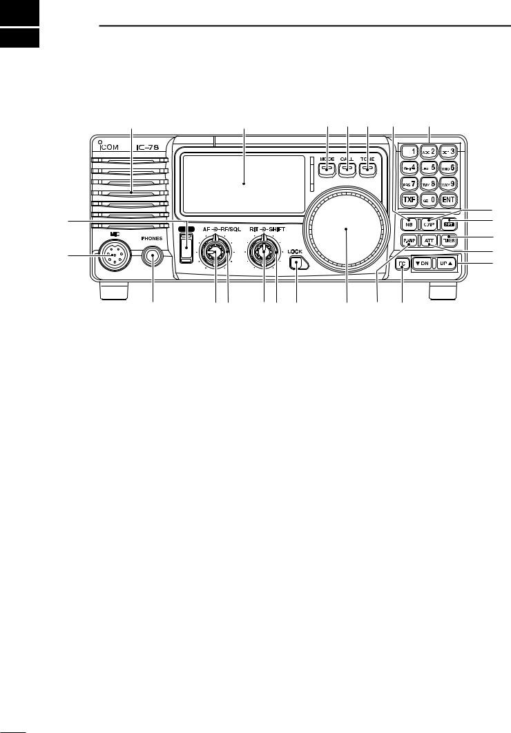
2 PANEL DESCRIPTION
■ Front panel |
|
|
|
|
Speaker |
Function Display |
@1 @0 !9 |
!8 |
!7 |
|
|
|
!6 |
q |
|
|
!5 |
|
PWR |
|
|
|
|
|
!4 |
w |
|
|
!3 |
|
|
|
|
|
|
|
!2 |
e |
r t |
y u i |
o !0 !1 |
qPOWER SWITCH [PWR]
Push momentarily to turn power ON.
•Turn the optional DC power supply ON in advance.
Push for 1 sec. to turn power OFF.
While pushing and holding [SET], push [PWR] to enter the initial set mode. (p. 28)
wMICROPHONE CONNECTOR [MIC]
Accepts supplied or optional microphone.
•See p. 45 for appropriate microphones.
•See p. 7 for microphone connector information.
eHEADPHONE JACK [PHONES] (p. 11) Accepts headphones.
•When headphones are connected, the internal speaker or connected external speaker does not function.
rAF CONTROL [AF] (inner control)
Varies the audio output level from the speaker.
tRF GAIN/SQUELCH CONTROL [RF/SQL]
(outer control; pgs. 15, 31)
Adjusts the squelch threshold level. The squelch removes noise output from the speaker (closed condition) when no signal is received.
•The squelch is available for all modes.
•The control can be set as the squelch plus RF gain controls or squelch control only (RF gain is fixed at maximum) in initial set mode.
y RIT CONTROL [RIT] (inner control; p. 19)
Shifts the receive frequency ±1.2 kHz for clear reception of an off frequency signal.
•Rotate the control clockwise to increase the frequency, or rotate the control counterclockwise to decrease the frequency. “  ” appears on the display.
uIF SHIFT CONTROLS [SHIFT]
(outer control; p. 20)
Shifts the center frequency of the receiver’s IF passband.
•Rotate the control clockwise to shift the center frequency higher, or rotate the control counterclockwise to shift the center frequency lower.
i LOCK SWITCH [LOCK] (p. 14)
Push momentarily to turn the dial lock function ON and OFF.
•The dial lock function electronically locks the channel selector.
oCHANNEL SELECTOR
Selects an operating channel, sets conditions in the quick/initial set mode items, etc.
!0PREAMP SWITCH [P.AMP] (p. 19) Push to turn the preamp ON or OFF.
!1FC SWITCH [CH]
Push to change the indication, channel comment or stored frequency. (p. 14)
This key action only for some versions.
Push for 1 sec. to entering into VFO mode. (p. 35)
!2MEMORY CHANNEL UP/DOWN SWITCHES [Ã DN]/[UP º]
Push to select the operating channel. (p. 13)
Push for 1 sec. to start scanning. (p. 14)
Push to select the quick/initial set mode items while quick/initial set mode is selected. (p. 28)
Push to select the digit of channel comment while editing. (p. 27)
2

!3ATTENUATOR SWITCH [ATT] (p. 19)
Push to turn the 20 dB attenuator function ON and OFF.
!4TUNER SWITCH [TUNER] (p. 18)
Push to turn the antenna tuner function ON and OFF.
Push for 1 sec. to manually tune the tuner.
•An optional antenna tuner must be connected.
•When the tuner cannot tune the antenna, the tuning circuit is bypassed automatically after 20 sec.
!5SET SWITCH [SET]
Push for 1 sec. to enter the quick set mode. (p. 28)
Push and hold [SET], then push [PWR] to enter the initial set mode. (p. 28)
Push to change the meter function; (p. 16)
•PO: indicates the relative RF output power.
•ALC: Indicates ALC level.
•SWR: Indicates the SWR over the transmission line.
!6MIC COMPRESSOR SWITCH [COMP] (p. 17) Turn the Mic. compressor function ON and OFF.
!7KEYPAD
The keypad can be used for several functions as described below:
[0] to [9]
—For entering operating channel number. (p. 13)
—Selects a character during channel comment programming. (p. 27)
[ENT]
—Direct channel number input. (p. 13)[TXF]
—Transmit frequency indication. (p.14)
—Selects a space and changes the editing digit during channel comment programming. (p. 27)
!8NOISE BLANKER SWITCH [NB] (p. 19)
Turns the noise blanker ON and OFF. The noise blanker reduces pulse-type noise such as that generated by automobile ignition systems. This function is not effective against non pulse-type noise.
Push [NB] for 1 sec. to enter the noise blanker level setting condition.
!9TONE SWITCH [TONE]
This key action may differ according to version.
Selects the call channel and emits a distress alarm tone from the speaker. (p. 36)
Transmits a distress alarm or alarm testing signal when pushed for 1 sec. (p. 36)
•Cancel the distress alarm tone emission, or distress alarm transmission.
Selects the tuning step item in the quick set mode directly.
No function is assigned.
PANEL DESCRIPTION 2
@0CALL SWITCH [CALL]
Push to select call channel.
•Push again to return to previous condition.
@1MODE SWITCH [MODE] (p. 15) Push to change an operating mode.
•Push [MODE] for 1 sec. during SSB mode to switch between LSB or USB.
•Push [MODE] for 1 sec. during CW or RTTY mode, to switch between CW and CW reverse or
RTTY and RTTY reverse. “ ” appears on the display.
3
2 PANEL DESCRIPTION
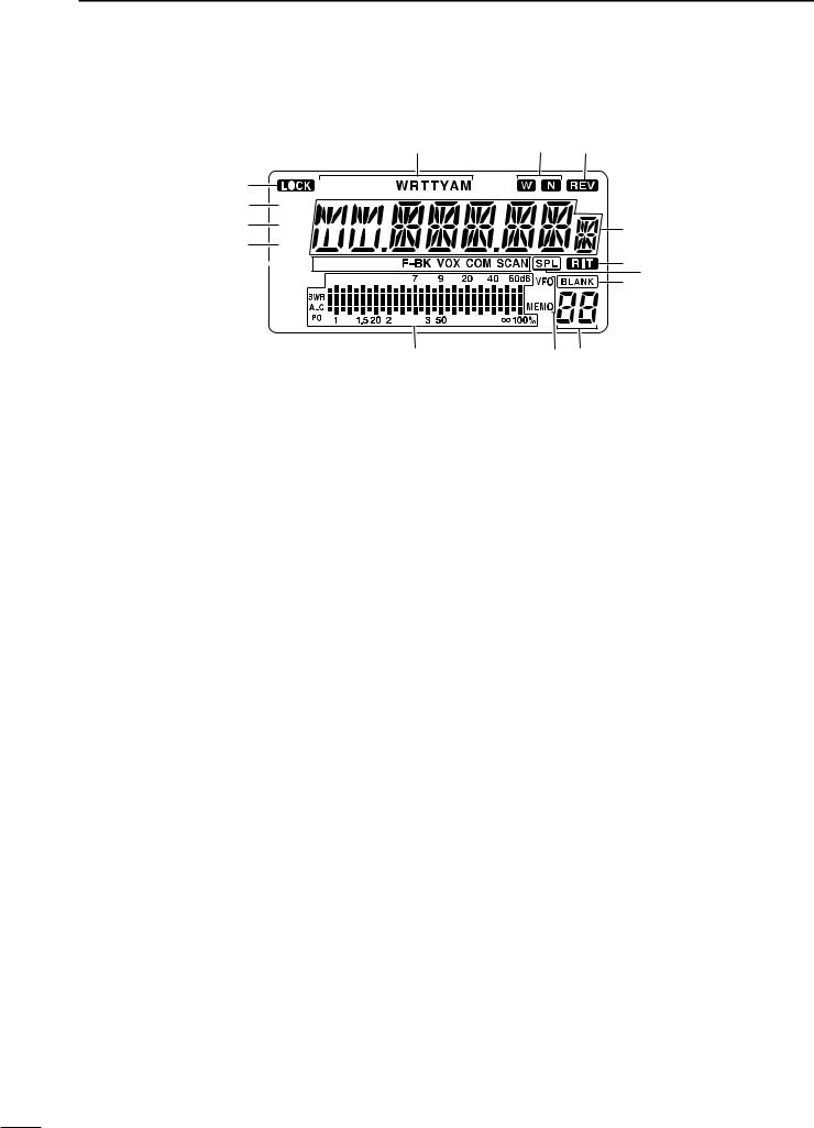
■ Function display
!6
q 


 w
w 

 e
e 

 r
r 


 t
t


 y
y


u
qLOCK INDICATOR (p. 14)
Appears when the dial lock function is in use.
wRECEIVE INDICATOR
Appears while receiving a signal or when the squelch is open.
eTUNE INDICATOR
Appears or disappears when the connected automatic tuner is tuned completely, depending on connected antenna tuner type.
Flashes while tuning.
rTRANSMIT INDICATOR
Appears while transmitting.
Flashes while transmit frequency is indicated.
tALARM INDICATOR
This indicator appears only some versions.
Appears while 2-tone alarm is emitting or transmitting
yFUNCTION INDICATORS
“P.AMP” appears when preamp is activated.
“ATT” appears when the RF attenuator is activated.
“NB” appears when the Noise Blanker is activated.
“BK” appears when the semi break-in function is selected in quick set mode.
“F-BK” appears when the full break-in function activates in CW mode. (p. 23)
“VOX” appears when the VOX function is selected in quick set mode.
“COM” appears when the speech compressor activates in SSB mode.
“SCAN” appears during scanning.
•Flashes when scan is paused.
uSIGNAL/SQL/RF-GAIN METER
Functions as an S-meter while receiving.
Functions as a Power, ALC or SWR meter while transmitting. (p. 16)
!5 !4
!3
!2
!1
!0
io
i VFO/MEMORY INDICATOR
“MEMO” appears during regular operation.
This indicator appears only some versions.
“VFO” appears during VFO operation.
oCHANNEL NUMBER READOUT (p. 13) Shows the selected channel number.
!0BLANK INDICATOR
Appears when no frequency programmed channel is selected.
!1SPLIT INDICATORS (p. 13)
Appears when the duplex channel, in which different frequencies between transmit and receive are programmed, is selected.
!2RIT INDICATOR (p. 19)
Appears when the RIT function is in use.
!3CHANNEL READOUT
Shows the memory names, or stored frequency of the selected channel.
!4REVERSE INDICATOR (p. 15)
Appears when the CW reverse or RTTY reverse mode is selected.
!5WIDE/NARROW FILTER INDICATORS (pgs. 21, 22)
“ ” appears when the wide IF filter is selected.“
  ” appears when the narrow IF filter is se-
lected.
!6MODE INDICATORS (p. 15)
Indicates the temporarily selected operating mode.
4
PANEL DESCRIPTION 2
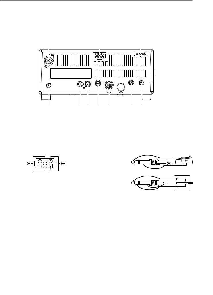
■ Rear panel
q |
w |
|
e |
|||
|
|
|
|
|
|
|
|
|
|
|
|
|
|
|
|
|
|
|
|
|
|
|
|
|
|
|
|
|
|
|
|
|
|
|
!0 |
o i u y |
t r |
qANTENNA TERMINAL [ANT] (p. 9)
Connects a 50 Ω antenna with a PL-259 connector and a 50 Ω coaxial cable.
wDC POWER SOCKET [DC 13.8V] (p. 10)
Accepts 13.8 V DC through the supplied DC power cable.
Rear panel view
eTUNER CONTROL SOCKET [TUNER] (p. 11) Accepts the control cable from an optional antenna tuner.
rREMOTE JACK [REMOTE] (p. 11)
For use with a personal computer for remote operation of transceiver functions, and data cloning between transceivers.
tEXTERNAL SPEAKER JACK [EXT SP]
Connects an 8 Ω external speaker, if desired.
•When an external speaker is connected, the internal speaker does not function.
yACCESSORY SOCKET [ACC] (p. 6)
Enables connection to external equipment such as a TNC for data communications or a linear amplifier, etc.
uELECTRONIC KEYER JACK [KEY]
Accepts a paddle to activate the internal electronic keyer.
•Selection between the internal electronic keyer and straight key operation can be made in initial set mode.
When connecting |
(Å) |
|
|
||
a straight key |
|
|
When connecting |
(dot) |
|
(com) |
||
a paddle |
||
(dash) |
||
|
iALC INPUT JACK [ALC]
Connects to the ALC output jack of a non-Icom linear amplifier.
oSEND CONTROL JACK [SEND]
Goes to ground while transmitting to control external equipment such as a linear amplifier.
• Max. control level: 16 V DC/2 A
!0GROUND TERMINAL [GND] (p. 9)
Connects the terminal to ground.
5
2 PANEL DESCRIPTION
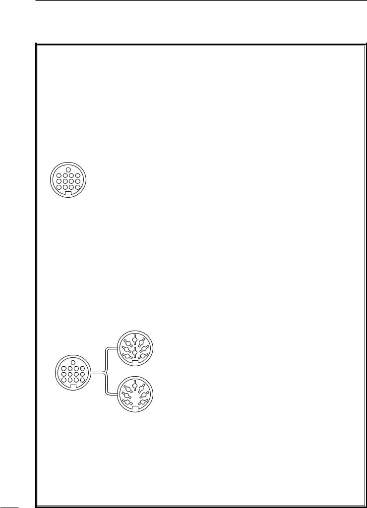
DACC SOCKET INFORMATION
•ACC socket
|
ACC |
|
PIN # |
NAME |
DESCRIPTION |
SPECIFICATIONS |
|||
|
|
|
|
1 |
8 V |
Regulated 8 V output. |
Output voltage |
: 8 V ±0.3 V |
|
|
|
|
|
Output current |
: Less than 10 mA |
||||
|
|
|
|
|
|
|
|||
|
|
|
|
|
|
|
|
|
|
|
|
|
|
2 |
GND |
Connects to ground. |
— |
|
|
|
|
|
|
|
|
|
|
|
|
|
|
|
|
|
|
Input/output pin. |
Ground level |
: –0.5 V to 0.8 V |
|
|
|
|
|
3 |
SEND |
Goes to ground when transmitting. |
|||
|
|
|
|
|
|
When grounded, transmits. |
Input current |
: Less than 20 mA |
|
|
|
|
|
|
|
|
|
||
|
|
|
|
|
|
|
|
|
|
|
|
|
|
4 |
BDT |
Data line. |
— |
|
|
|
|
|
|
|
|
|
|
|
|
|
|
|
|
5 |
BAND |
Band voltage output. |
|
|
|
|
|
|
|
|
|
|
|
|
|
|
13 |
|
|
6 |
ALC |
ALC voltage output. |
Control voltage |
: –4 V to 0 V |
|
9 |
10 |
11 |
12 |
Input impedance : More than 10 kΩ |
|||||
|
|
|
|||||||
5 |
6 |
7 |
8 |
|
|
|
|
|
|
7 |
NC |
— |
— |
— |
|||||
1 |
2 |
3 |
4 |
||||||
|
|
|
|
|
|
|
|
|
|
Rear panel |
8 |
13.8 V |
13.8 V output when power is ON. |
Output current |
: Max. 1 A |
||||
|
|
|
|
|
|||||
9 |
TKEY |
Key line. |
— |
|
|||||
|
view |
|
|
||||||
|
|
|
|
|
|
|
|
|
|
|
|
|
|
10 |
FSKK |
RTTY key input. |
Ground level |
: –0.5 V to 0.8 V |
|
|
|
|
|
Input current |
: Less than 10 mA |
||||
|
|
|
|
|
|
|
|||
|
|
|
|
|
|
|
|
||
|
|
|
|
11 |
MOD |
Modulation input. |
Input impedance : 10 kΩ |
||
|
|
|
|
Input level |
: Approx. 100 mV rms |
||||
|
|
|
|
|
|
|
|||
|
|
|
|
|
|
|
|
||
|
|
|
|
12 |
AF |
AF detector output. |
Output impedance: 4.7 kΩ |
||
|
|
|
|
Fixed, regardless of [AF] position. |
Output level |
: 100–300 mV rms |
|||
|
|
|
|
|
|
||||
|
|
|
|
|
|
|
|
|
|
|
|
|
|
13 |
SQLS |
Squelch output. |
SQL open |
: Less than 0.3 V/5 mA |
|
|
|
|
|
Goes to ground when squelch opens. |
SQL closed |
: More than 6.0 V/100 µA |
|||
|
|
|
|
|
|
|
|
|
|
• When connecting the ACC conversion cable (OPC-599)
2 |
5 |
FSKK |
AF |
|
4 |
GND |
SQLS |
||
1 |
3 |
|||
SEND |
13.8 V |
|||
8 |
7 |
|||
6 |
MOD |
ALC |
||
13 |
|
|||
|
|
|
9 10 11 12
5 6 7 8
ACC 1
1 2 3 4
2 |
5 |
8 V |
ALC |
|
4 |
GND |
NC |
||
1 |
3 |
|||
SEND |
13.8 V |
|||
6 |
7 |
|||
BAND |
|
|||
|
|
|
ACC 2
6
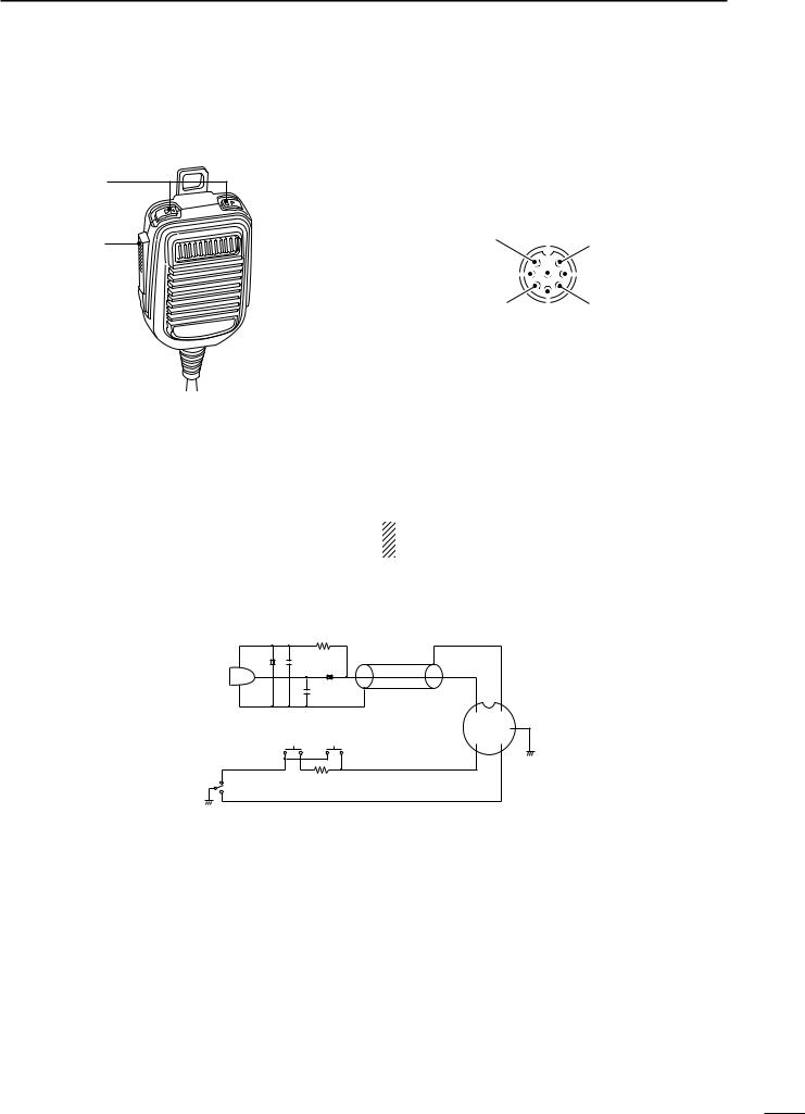
■ Microphone (HM-36)
• DESCRIPTION
q
w
qUP/DOWN SWITCHES [UP]/[DN]
Change the selected readout frequency or memory channel.
•Continuous pushing changes the frequency or memory channel number continuously.
•The [UP]/[DN] switch can simulate a key paddle. Preset in the CW PADDL in initial set mode. (p. 32)
wPTT SWITCH
Push and hold to transmit; release to receive.
PANEL DESCRIPTION 2
• MICROPHONE CONNECTOR
(Front view)
iMain readout AF output (varies with [AF])
q Microphone input |
|
|
|
u GND |
||||
|
|
|
|
|
|
|
||
|
|
|
|
|
|
|
(Microphone ground) |
|
w +8 V DC output |
|
|
|
|
|
y GND (PTT ground) |
||
|
|
|||||||
|
|
|||||||
|
|
|
|
|||||
e Frequency up/down |
|
|
|
t PTT |
||||
|
|
|
|
|
|
|||
|
|
r Main readout squelch switch |
||||||
|
|
|
|
|
|
|
|
|
[MIC] |
FUNCTION |
|
DESCRIPTION |
|||||
Pin No. |
|
|||||||
|
|
|
|
|
|
|
||
w |
+8 V DC output |
Max. 10 mA |
||||||
|
|
|
||||||
e |
Frequency up |
Ground |
||||||
|
|
|||||||
Frequency down |
Ground through 470 Ω |
|||||||
|
|
|
||||||
r |
Squelch open |
“Low” level |
||||||
Squelch closed |
“High” level |
|||||||
|
||||||||
|
|
|
|
|
|
|
|
|
CAUTION: DO NOT short pin 2 to ground as this can damage the internal 8 V regulator.
• HM-36 SCHEMATIC DIAGRAM
|
MICROPHONE |
MICROPHONE CABLE |
MICROPHONE PLUG |
||
|
10 |
+ |
2 k |
|
|
|
4700 p |
|
|
||
|
|
|
+ |
|
|
MIC |
|
|
0.33 |
|
|
ELEMENT |
|
4700 p |
|
|
|
|
|
|
|
||
|
|
|
|
q |
u |
|
|
|
|
w |
i y |
|
|
DOWN |
UP |
e r t |
|
PTT |
RECEIVE |
|
470 |
|
|
|
|
|
|
||
TRANSMIT
7
3 INSTALLATION AND CONNECTIONS
■ Unpacking |
■ Antenna connection |
After unpacking, immediately report any damage to the delivering carrier or dealer. Keep the shipping cartons.
For a description and a diagram of accessory equipment included with the IC-78, see ‘Supplied accessories’ on p. 1 of this manual.
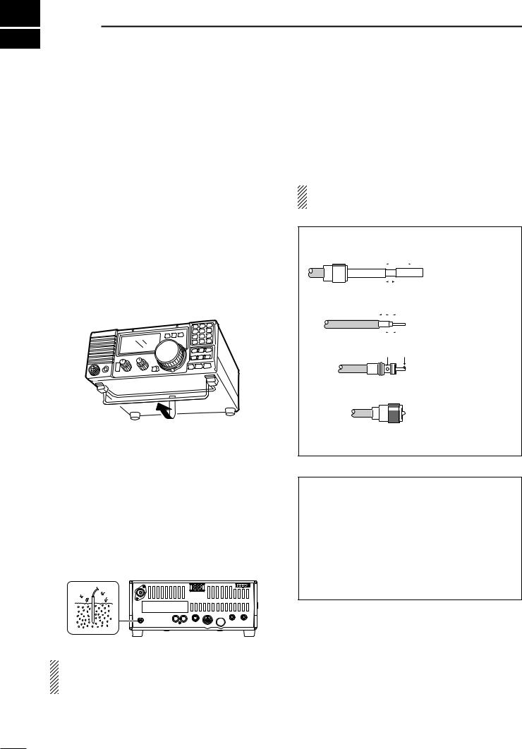
■ Selecting a location
Select a location for the transceiver that allows adequate air circulation, free from extreme heat, cold, or vibrations, and away from TV sets, TV antenna elements, radios and other electro-magnetic sources.
The base of the transceiver has an adjustable stand for desktop use. Set the stand to one of two angles depending on your operating conditions.
■ Grounding
To prevent electrical shock, television interference (TVI), broadcast interference (BCI) and other problems, ground the transceiver through the GROUND terminal on the rear panel.
For best results, connect a heavy gauge wire or strap to a long earth-sunk copper rod. Make the distance between the [GND] terminal and ground as short as possible.
For radio communications, the antenna is of critical importance, along with output power and sensitivity. Select antenna(s), such as a well-matched 50 Ω antenna, and feed line. 1.5:1 or better of Voltage Standing Wave Ratio (VSWR) is recommended for your desired band. Of course, the transmission line should be a coaxial cable.
CAUTION: Protect your transceiver from lightning by using a lightning arrestor.
PL-259 CONNECTOR INSTALLATION EXAMPLE
q |
|
30 mm |
|
|
||||||
|
|
|
|
|
|
|
|
|
|
|
|
|
|
|
|
|
|
|
|
|
|
|
|
|
|
|
|
|
|
|
|
|
|
|
|
|
|
|
|
|
|
||
|
|
|
|
|
|
|
|
|
|
|
Coupling ring |
10 mm (soft solder) |
|||||||||
w |
10 mm |
Soft |
||||||||
|
|
|
|
|
|
|
||||
|
|
|
|
|
|
|
solder |
|||
|
|
|
|
|
|
|
|
|
|
|
|
|
|
|
|
|
|
|
|
|
|
|
|
|
|
|
|
|
|
|
|
|
|
|
|
|
|
1–2 mm |
|||||
Slide the coupling ring down. Strip the cable jacket and soft solder.
Strip the cable as shown at left. Soft solder the center conductor.
e |
solder |
solder |
|
|
|
|
Slide |
the |
connector |
||
|
|
||||
|
|
body on and solder it. |
|||
r |
|
Screw |
the |
coupling |
|
|
|
ring |
onto |
the |
|
|
|
connector body. |
|
||
30 mm ≈9⁄8 in 10 mm ≈3⁄8 in 1–2 mm ≈1⁄16 in
Antenna SWR
Each antenna is tuned for a specified frequency range and SWR may be increased out-of-range. When the SWR is higher than approx. 2.0:1, the transceiver’s power drops to protect the final transistor. In this case, an antenna tuner is useful to match the transceiver and antenna. Low SWR allows full power for transmitting even when using the antenna tuner. The IC-78 has an SWR meter to monitor the antenna SWR continuously.
RWARNING: NEVER connect the [GND] terminal to a gas or electric pipe, since the connection could cause an explosion or electric shock.
8
■Required connections
•Front panel
MICROPHONES (p. 45)
HM-36
SM-20 or SM-6,
SM-8
• Rear panel
ANTENNA
[Example]: 1.8–30 MHz bands
AH-710
GROUND (p. 8)
Use the heaviest gauge wire or strap available and make the connection as short as possible.
Grounding prevents electrical shocks, TVI and other problems.
INSTALLATION AND CONNECTIONS 3
PWR
DC POWER SUPPLY
PS-85
CW KEY
A straight key can be used when the internal electronic keyer is turned OFF in “CW PADDL” ininitial set mode. (p. 32)
9
3 INSTALLATION AND CONNECTIONS
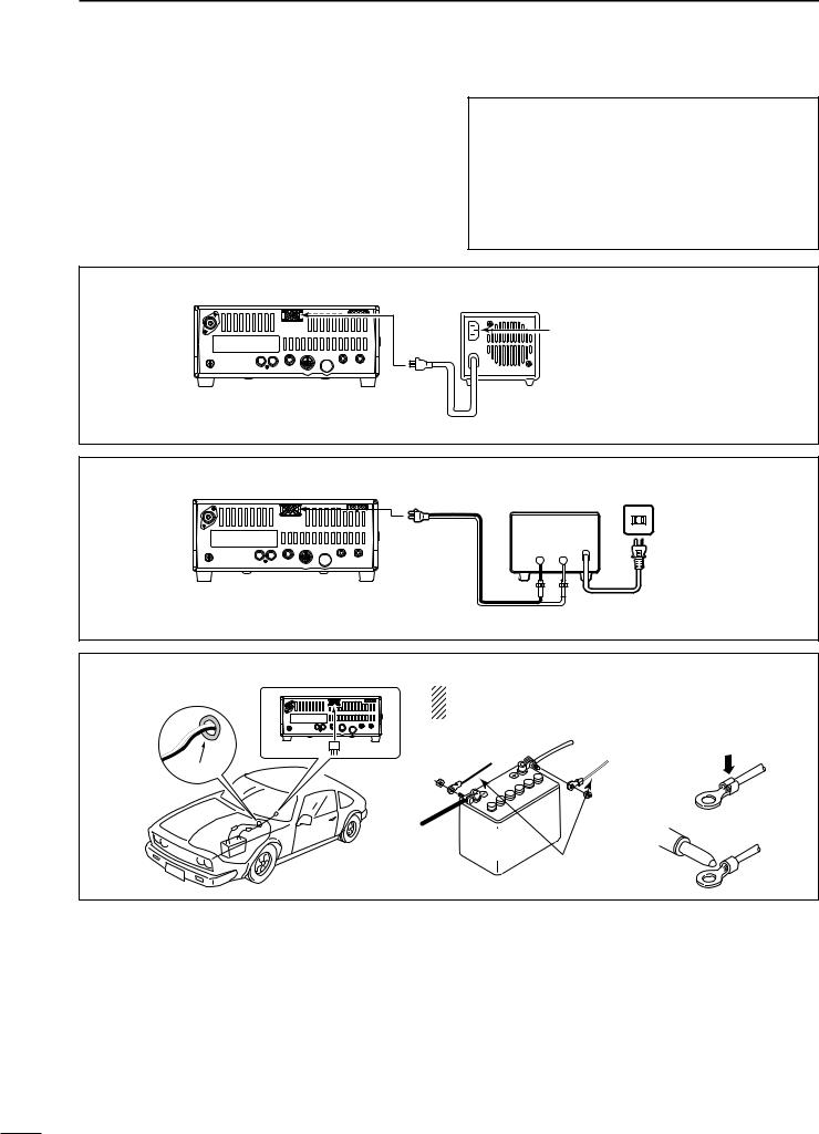
■ Power supply connections
Use an optional PS-85 DC POWER SUPPLY when operating the IC-78 with AC power. Refer to the diagrams below.
CAUTION: Before connecting the DC power cable, check the following important items. Make sure:
• The [PWR] switch is OFF.
•Output voltage of the power source is 12–15 V when you use a non-Icom power supply.
• DC power cable polarity is correct.
Red |
: positive + terminal |
Black |
: negative _ terminal |
CONNECTING PS-85 DC POWER SUPPLY
PS-85 |
DC power socket
Connect to an AC outlet using the supplied AC cable.
DC power cable
CONNECTING NON-ICOM DC POWER SUPPLY
|
DC power supply AC outlet |
DC power |
13.8 V 20 A |
|
|
socket |
_ + |
|
AC cable |
_black |
|
Supplied |
+red |
DC power cable |
20 A fuses |
CONNECTING A VEHICLE BATTERY
NEVER connect to |
NOTE: Use terminals for |
|
a 24 V battery. |
the cable connections. |
|
+ red |
Crimp |
|
_ black |
|
|
Grommet |
|
|
12 V |
Solder |
|
battery |
||
|
||
Supplied |
|
|
DC power cable |
||
10

INSTALLATION AND CONNECTIONS 3
■Advanced connections
•Front panel
PWR
MIC
The AFSK modulation signal can be input from [MIC]. (p. 25)
HEADPHONES
• Rear panel
AT-120,
AT-130, or
AH-4 (p. 44)
with
AH-2b or long wire
ANTENNA
Connects a linear amplifier, etc. 
[REMOTE] (pgs. 41, 42)
Used for computer control and transceive operation, and cloning operation between transceivers.
ACC SOCKETS (p. 6)
[SEND], [ALC] |
EXTERNAL SPEAKER (p. 44) |
Used for connecting a |
|
non-Icom linear ampli- |
|
fier. |
|
|
SP-21, etc. |
11
3 INSTALLATION AND CONNECTIONS
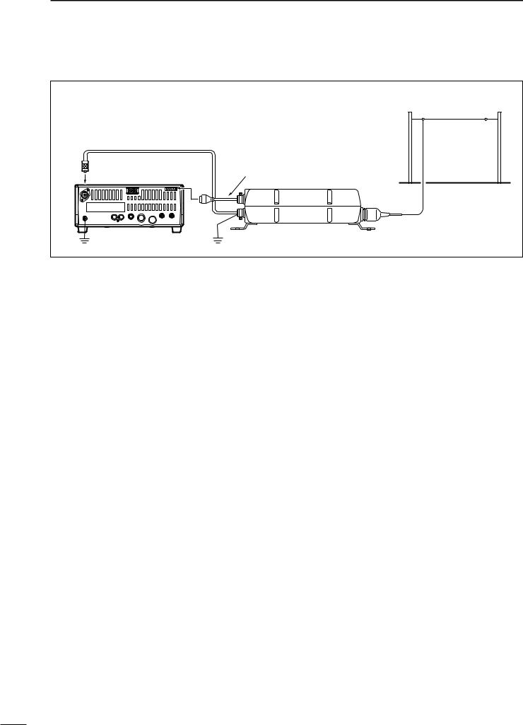
■ External antenna tuners
CONNECTING AN ANTENNA TUNER (p. 44)
Long wire or optional AH-2b
Coaxial cable (from the tuner)
Control cable
IC-78
AT-120/AT-130/AH-4
Ground |
Ground |
12
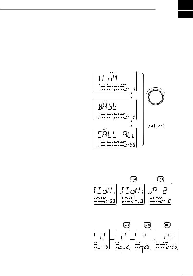
■ Selecting a channel
The transceiver has 99 memory channels. However, the number of channels can be restricted in initial set mode (p. 32) depending on your needs. A total of 3 ways of channel selections are available to suit your operating style.
DUsing the channel selector
Rotate the channel selector clockwise (channel number increases) or counterclockwise (channel number decreases) to select desired channel.
This is the most useful way of channel selection.
DUsing up/down switches
Push [Ã DN]/[UP º] on the front panel or the microphone to select the desired channel.
This way is convenient when changing a small number of channels.
•When a duplex channel (different frequencies between transmit and receive) is selected, “ ” appears.
DUsing the keypad
Enter the number of the desired channel number using the keypad (0 to 9), then push [ENT].
This way is convenient for remembering the usage and stored channel number, or when changing large a number of channels.
•When a duplex channel (different frequencies between transmit and receive) is selected, “ ” appears.
•When a blank channel (no frequency is programmed) is selected, “ ” appears.
OPERATION 4
Rotate the channel selector
Channel 1
or
Push [Ã DN]/[UP º]
switch
Channel 2
to select a channel
Channel 99
• Example 1— selecting channel 8
Push |
Push |
|
Blinks |
|
• Example 2— selecting channel 25 |
|
|
Push |
Push |
Push |
Blinks Blinks
13
 Loading...