


BASIC MANUAL
VHF/UHF ALL MODE TRANSCEIVER
|9700

Thank you for choosing this Icom product. The IC-9700 VHF/UHF ALL MODE TRANSCEIVER is designed and built with Icom’s state of the art technology and craftsmanship. With proper care, this product should provide you with years of trouble-free operation. We appreciate you making the IC-9700 your transceiver of choice, and hope you agree with Icom’s philosophy of “technology first.” Many hours of research and development went into the design of your IC-9700.
IMPORTANT
READ ALL INSTRUCTIONS carefully completely before using the transceiver.
SAVE THIS INSTRUCTION MANUAL— This instruction manual contains basic operating instructions for the IC-9700. For advance operating instructions, see the Advanced Manual for details. The Advance Manual is available at the following internet address: http://www.icom.co.jp/world/support/
EXPLICIT DEFINITIONS
WORD |
DEFINITION |
|
R DANGER! |
Personal death, serious injury or an |
|
explosion may occur. |
||
|
||
R WARNING! |
Personal injury, fire hazard or electric |
|
shock may occur. |
||
|
||
CAUTION |
Equipment damage may occur. |
|
|
Recommended for optimum use. No |
|
NOTE |
risk of personal injury, fire or electric |
|
|
shock. |
FEATURES
••RF Direct Sampling System
The IC-9700 employs an RF direct sampling system. RF signals are directly converted to digital data in the ADC, and then processed in the FPGA. This system is a leading technology, marking an epoch in amateur radio.
The 1200 MHz band uses a downconversion IF sampling.
••Real-Time Spectrum Scope
The spectrum scope is class-leading in resolution, sweep speed and dynamic range. When you touch the scope screen on the intended signal, the touched area is magnified. The large 4.3 inch color TFT touch LCD offers intuitive operation.
••D-STAR operation
The IC-9700 has the D-STAR Repeater (DR) function. Moreover, by using the DD mode, you can browse the Internet through a repeater station.
••Satellite operation
The IC-9700 has 99 satellite memory channels for both uplink and downlink frequencies and mode.
••“IP+” Function
The IP Plus function improves 3rd order intercept point (IP3) performance. When a weak signal is received adjacent to strong interference, the AD converter is optimized against signal distortion.
••A 4.3 inch touch panel color display
••Multi-function control for easy settings
SUPPLIED ACCESSORIES
Spare fuse |
Spare fuse |
(5 A) |
(25 A) |
Hand microphone
CW key plug |
DC power cable |
(3.5 mm: 1/8" Stereo) |
(3 m: 9.8 ft) |
LDifferent types of accessories may be supplied, or may not be supplied depending on the transceiver version.
This product includes RTOS “RTX” software, and is licensed according to the software license.
This product includes “zlib” open source software, and is licensed according to the open source software license.
This product includes “libpng” open source software, and is licensed according to the open source software license.
Refer to the “About the Licenses” page at the end of this manual for information on the open source software being used in this product.
i
FCC INFORMATION
This equipment has been tested and found to comply with the limits for a Class B digital device, pursuant to part 15 of the FCC Rules. These limits are designed to provide reasonable protection against harmful interference in a residential installation. This equipment generates, uses and can radiate radio frequency energy and, if not installed and used in accordance with the instructions, may cause harmful interference to radio communications. However, there is no guarantee that interference will not occur in a particular installation. If this equipment does cause harmful interference to radio or television reception, which can be determined by turning the equipment off and on, the user is encouraged to try to correct the interference by one or more of the following measures:
••Reorient or relocate the receiving antenna. ••Increase the separation between the equipment
and receiver.
••Connect the equipment into an outlet on a circuit different from that to which the receiver is connected.
••Consult the dealer or an experienced radio/TV technician for help.
CAUTION: Changes or modifications to this device, not expressly approved by Icom Inc., could void your authority to operate this device under FCC regulations.
Icom is not responsible for the destruction, damage to, or performance of any Icom or non-Icom equipment, if the malfunction is because of: ••Force majeure, including, but not limited to, fires, earthquakes, storms, floods, lightning, or other natural disasters, disturbances, riots, war, or
radioactive contamination.
••The use of Icom transceivers with any equipment that is not manufactured or approved by Icom.
ABOUT CE AND DOC
Hereby, Icom Inc. declares that the versions of IC-9700 which have the “CE” symbol on the product, comply with the essential requirements of the Radio
Equipment Directive, 2014/53/EU, and the restriction of the use of certain hazardous substances in electrical and electronic equipment Directive, 2011/65/EU. The full text of the EU declaration of conformity is available at the following internet address:
http://www.icom.co.jp/world/support/
DISPOSAL
The crossed-out wheeled-bin symbol on
your product, literature, or packaging reminds you that in the European
Union, all electrical and electronic products, batteries, and accumulators (rechargeable batteries) must be taken
to designated collection locations at the end of their working life. Do not dispose of these products as unsorted municipal waste.
Dispose of them according to the laws in your area.
TRADEMARKS
Icom, Icom Inc. and the Icom logo are registered trademarks of Icom Incorporated (Japan) in Japan, the United States, the United Kingdom, Germany, France, Spain, Russia, Australia, New Zealand and/or other countries.
Microsoft and Windows are registered trademarks of Microsoft Corporation in the United States and/or other countries.
Adobe, Acrobat, and Reader are either registered trademarks or trademarks of Adobe Systems Incorporated in the United States and/or other countries.
AMBE+2 is a trademark and property of Digital Voice Systems Inc.
All other products or brands are registered trademarks or trademarks of their respective holders.
ii

ABOUT THE TOUCH SCREEN
DD Touch operation
In the Advanced manual or Basic manual, the touch operation is described as shown below, with the beep tone ON.
Touch
If the display is touched briefly, one short beep sounds.
Touch for 1 second
If the display is touched for 1 second, one short and one long beep sound.
DD Touch screen precautions
••The touch screen may not properly work when the
LCD protection film or sheet is attached. ••Touching the screen with your finger nails, sharp topped object and so on, or touching the screen
hard may damage it.
••Tablet PC operations such as flick, pinch in and pinch out cannot be performed on this touch screen.
DD Touch screen maintenance
••If the touch screen becomes dusty or dirty, wipe it clean with a soft, dry cloth.
••When you wipe the touch screen, be careful not to push it too hard or scratch it with your finger nails.
Otherwise you may damage the screen.
ABOUT THE MANUALS
The following manuals or Guide for this transceiver are published at the following internet address: http://www.icom.co.jp/world/support/
••Advanced Manual (English)
Instructions for advanced operations in English.
••Basic Manual (English)
Instructions for basic operations, the same as this manual.
••Basic Manual (Multi-language)
Instructions for basic operations in multiple languages.
••CI-V Reference Guide (English)
Describes the control commands used in remote control operation (serial communication with CI-V).
For Reference
••HAM Radio Terms (English)
A glossary of HAM radio terms in English.
To read the manuals or Guide, Adobe® Acrobat® Reader® is required. If you have not installed it, please down load the Adobe® Acrobat® Reader® and install it to your PC. You can download it from Adobe Systems Incorporated’s website.
A PC with the following Operating System is required. ••Microsoft® Windows® 10
••Microsoft® Windows® 8.1 ••Microsoft® Windows® 7
VOICE CORDING TECHNOLOGY
The AMBE+2™ voice coding Technology embodied in this product is protected by intellectual property rights including patent rights, copyrights and trade secrets of Digital Voice Systems, Inc. This voice coding Technology is licensed solely for use within this Communications Equipment.
The user of this Technology is explicitly prohibited from attempting to extract, remove, decompile, reverse engineer, or disassemble the Object Code, or in any other way convert the Object Code into a human-readable form.
U.S. Patent Nos.
#8,595,002, #8,359,197, #8,315,860, #8,200,497, #7,970,606, #6,912,495 B2.
iii
ABOUT THE INSTRUCTIONS
The Advanced and Basic manuals are described in the following manner.
“ ” (Quotation marks):
Used to indicate icons, setting items, and screen titles displayed on the screen.
The screen titles are also written in uppercase letters. (Example: FUNCTION screen)
[ ] (brackets):
Used to indicate keys.
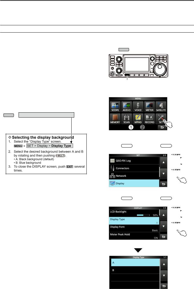
Routes to the Set modes and Setting screens
Routes to the Set mode, Setting screens and the setting items are described in the following manner.
MENU » SET > Display > Display Type
Instruction example
iv
Detailed instruction
1. Push MENU .
Push
••Opens the MENU screen.
2. Touch [SET].
MENU screen ••Opens the SET screen.
3.Rotate  MULTI , and then push
  MULTI to select
“Display.”
 Rotate
 Push
Push
SET screen
4.Rotate  MULTI , and then push
  MULTI to select
“Display Type.”
 Rotate
 Push
Push
DISPLAY screen
“Display Type” screen

TABLE OF CONTENTS
IMPORTANT i FEATURES i EXPLICIT DEFINITIONS i SUPPLIED ACCESSORIES i FCC INFORMATION ii ABOUT CE AND DOC ii DISPOSAL ii TRADEMARKS ii ABOUT THE TOUCH SCREEN iii VOICE CORDING TECHNOLOGY iii ABOUT THE MANUALS iii ABOUT THE INSTRUCTIONS iv PRECAUTIONS vii
1 PANEL DESCRIPTION 1-1
Front panel 1-1 Rear panel 1-3 Touch screen display 1-4 DDFUNCTION screen 1-6 DDMENU screen 1-6 DDQUICK MENU 1-6 DDMulti-function menus 1-7 Multi-function dial 1-7 Keyboard entering and editing 1-8 DDEntering and editing characters 1-8 DDKeyboard types 1-9 DDEntering and editing 1-9 DDEntering and editing example 1-10
2 INSTALLATION AND CONNECTIONS 2-1
Selecting a location 2-1 Using the desktop stands 2-1 Connecting an external DC power supply 2-1 Heat dissipation 2-1 Grounding 2-1
3 BASIC OPERATION 3-1
When first applying power 3-1 Turning power ON or OFF 3-1 Adjusting the volume level 3-1 Selecting the VFO and Memory modes 3-1 Using the VFO mode 3-1
DDSelecting VFO A or VFO B 3-1 DDEqualizing VFO A and VFO B 3-1 Dualwatch operation 3-2 Selecting the Main and Sub bands 3-2 DDSwapping the Main band and Sub band 3-2 Selecting the operating band 3-3 DDUsing the band stacking registers 3-3 Selecting the operating mode 3-3
Setting the frequency 3-4 DDUsing the Main Dial 3-4 DDAbout the Tuning Step function 3-4 DDChanging the Tuning Step 3-4 DDAbout the 1 MHz Step Tuning function 3-4 DDAbout the 1 Hz step Fine Tuning function 3-4
DDAbout the 1/4 Tuning function 3-5
DDAbout the Auto Tuning Step function 3-5 DDDirectly entering a frequency 3-5 DDBand Edge Beep 3-6 DDEntering a Band Edge 3-7 RF gain and SQL level 3-10 Dial Lock function 3-10 Adjusting the transmit output power 3-10 DDAdjusting the transmit output power 3-10 Transmit Power Limit function 3-10 Meter display 3-11 DDMeter display selection 3-11 DDMulti-function meter 3-11 Adjusting the microphone gain 3-11
4 RECEIVING AND TRANSMITTING 4-1
Preamplifiers 4-1 Attenuator 4-1 RIT function 4-1 DDRIT monitor function 4-1 DDCW Auto Tuning function 4-1 AGC function control 4-2
DDSelecting the AGC time constant
preset value 4-2 DDSetting the AGC time constant 4-2 Using the Digital Twin PBT 4-3 Selecting the IF filter 4-4 Selecting the IF filter shape 4-4 Noise Blanker 4-5 DDAdjusting the NB level and time 4-5 Noise Reduction 4-6 DDAdjusting the Noise Reduction level 4-6 Notch Filter 4-6
DDSelecting the Notch filter type 4-6 DDSetting the Manual Notch filter 4-6
Monitor function 4-7 IP Plus function 4-7 Setting the Speech Compressor 4-8
DDSetting before using the Speech
Compressor function 4-8 DDUsing the Speech Compressor function 4-8 Split frequency operation 4-9 DDUsing the Quick Split function 4-9 DDUsing the receive and transmit frequencies
set to VFO A and VFO B 4-9 Split Lock function 4-10 Setting the transmit filter width 4-10
v

Operating CW 4-10 DDSetting the CW pitch control 4-10 DDSetting the key speed 4-10 DDUsing the Break-in function 4-11 DDMonitoring the CW side tone 4-11 DDAbout the electronic Keyer function 4-12
5 SCOPE OPERATION 5-1
Spectrum scope screen 5-1 DDMarker 5-1 DDUsing the Spectrum Scope 5-1 DDCenter mode 5-2 DDFixed mode 5-2 DDTouch screen operation 5-2 DDMini scope screen 5-2
Audio scope screen 5-3 DDAUDIO SCOPE SET screen 5-3
6 SD CARD 6-1
About the SD cards 6-1 Saving data 6-1 Inserting 6-1 Formatting 6-1 Unmounting 6-2 Saving the setting data 6-2 Loading the saved data 6-3 Deleting a data file 6-4 Displaying the card information 6-4 Importing or Exporting a CSV format file 6-5
DDImporting 6-5 DDExporting 6-6 About the SD card folders 6-7
7 SATELLITE COMMUNICATION 7-1
Satellite communications outline 7-1 Selecting the satellite mode 7-1 DDSetting the satellite VFO 7-1 DDSelecting NOR/REV tracking 7-1 Loop test procedure 7-2 Satellite operation 7-3 Satellite memories 7-3 DDSatellite memory screen 7-3
8 SET MODE 8-1
Set mode description 8-1 Tone Control/TBW 8-2 Function 8-2 My Station 8-5 DV/DD Set 8-6 QSO/RX Log 8-8 Connectors 8-11 Network 8-14 Display 8-15 Time Set 8-18 SD Card 8-18 Others 8-19
vi
9 CLOCK 9-1
Setting the date and time 9-1 DDSetting the date 9-1 DDSetting the current time 9-1 DDSetting the UTC offset 9-1 NTP function 9-1 DDUsing the NTP Time Synchronize function 9-1 DDUsing the NTP function 9-1
10 MAINTENANCE 10-1
Cleaning 10-1 Replacing fuse 10-1 Resetting 10-2 DDPartial reset 10-2 DDAll reset 10-2 Cloning 10-3 Touch screen calibration function 10-5 Troubleshooting 10-6 DDD-STAR operation 10-8
11 SPECIFICATIONS 11-1
DDGeneral 11-1 DDTransmitter 11-2 DDReceiver 11-3
12 OPTIONS 12-1
Options 12-1 Mounting the MB-118 12-2 Attaching the MB-123 12-2
13 CONNECTOR INFORMATION 13-1
[ACC] 13-1 [DC 13.8 V] 13-1 [PHONES] 13-1 [KEY] 13-2 [EXT-SP MAIN] / [EXT-SP SUB] 13-2 [USB] 13-2 [LAN] 13-2 [DATA] 13-2 [MIC] 13-3 [REMOTE] 13-3 [REF IN 10MHz] 13-3 [144MHz ANT] 13-3 [430MHz ANT] 13-3 [1200MHz ANT] 13-3
ABOUT THE LICENSES I INDEX II

PRECAUTIONS
R DANGER HIGH RF VOLTAGE! NEVER touch an antenna or antenna connector while transmitting. This could cause an electrical shock or burn.
R DANGER! NEVER operate the transceiver near unshielded electrical blasting caps or in an explosive atmosphere. This could cause an explosion and death.
R WARNING RF EXPOSURE! This device emits Radio Frequency (RF) energy. Extreme caution should be observed when operating this device. If you have any questions regarding RF exposure and safety standards please refer to the Federal Communications Commission
Office of Engineering and Technology’s report on
Evaluating Compliance with FCC Guidelines for Human Radio Frequency Electromagnetic Fields (OET Bulletin 65).
R WARNING! NEVER operate the transceiver with a headset or other audio accessories at high volume levels. If you experience a ringing in your ears, reduce the volume or discontinue use.
R WARNING! NEVER apply AC power to the [DC13.8V] socket on the transceiver rear panel. This could cause a fire or damage the transceiver.
R WARNING! NEVER apply more than 16 V DC to the
[DC13.8V] socket on the transceiver rear panel. This could cause a fire or damage the transceiver.
R WARNING! NEVER reverse the DC power cable polarity. This could cause a fire or damage the transceiver.
R WARNING! NEVER remove the fuse holder on the DC power cable. Excessive current caused by a short could cause a fire or damage the transceiver.
R WARNING! NEVER let metal, wire or other objects contact the inside of the transceiver, or make incorrect contact with connectors on the rear panel. This could cause an electric shock or damage the transceiver.
R WARNING! NEVER operate or touch the transceiver with wet hands. This could cause an electric shock or damage to the transceiver.
R WARNING! NEVER operate the equipment if you notice an abnormal odor, sound or smoke. Immediately turn OFF the power and/or remove the DC power cable. Contact your Icom dealer or distributor for advice.
R WARNING! NEVER put the transceiver on an unstable place where the transceiver may suddenly move or fall. This could cause an injury or damage the transceiver.
R WARNING! NEVER operate the transceiver during a lightning storm. It may result in an electric shock, cause a fire or damage the transceiver. Always disconnect the power source and antenna before a storm.
CAUTION: DO NOT expose the transceiver to rain, snow or any liquids. They could damage the transceiver.
CAUTION: DO NOT change the internal settings of the transceiver. This could reduce transceiver performance and/or damage to the transceiver. The transceiver warranty does not cover any problems caused by unauthorized internal adjustments.
CAUTION: DO NOT install or place the transceiver in a place without adequate ventilation, or block any cooling vents on the top, rear, sides or bottom of the transceiver. Heat dissipation may be reduced and damage the transceiver.
CAUTION: NEVER use harsh solvents such as Benzine or alcohol when cleaning. This could damage the transceiver surfaces. If the surface becomes dusty or dirty, wipe it clean with a soft, dry cloth.
CAUTION: NEVER leave the transceiver in areas with temperatures below –10°C (+14°F) or above +60°C (+140°F) for mobile operations.
CAUTION: DO NOT place the transceiver in excessively dusty environments. This could damage the transceiver.
CAUTION: DO NOT place the transceiver against walls or putting anything on top of the transceiver. This may overheat the transceiver.
CAUTION: DO NOT set the transceiver’s RF output power to more than a connected linear amplifier’s maximum input level. Otherwise, the linear amplifier will be damaged.
CAUTION: DO NOT use non-Icom microphones. Other microphones have different pin assignments, and may damage the transceiver.
BE CAREFUL! The transceiver will become hot when operating the transceiver continuously for long periods of time.
NEVER leave the transceiver in an insecure place to avoid use by unauthorized persons.
Turn OFF the transceiver’s power and/or disconnect the DC power cable when you will not use the transceiver for long period of time.
The LCD display may have cosmetic imperfections that appear as small dark or light spots. This is not a
malfunction or defect, but a normal characteristic of LCD displays.
vii

PANEL DESCRIPTION 1
Front panel
This section describes the keys, controls and dials that you use to operate the IC-9700. |
|
|
|
|
1 |
|||||||
Refer to the pages posted beside each key, control, or dial for details. |
|
|
|
|
|
|
|
|||||
|
o |
|
|
|
|
|
|
|
|
|
|
|
q |
|
o VOLUME CONTROL AF RF/SQL / M/S /OFF (p. 3-1) |
||||||||||
|
LThe upper control is for the Main band, and the |
|||||||||||
|
!4 |
|||||||||||
w |
|
lower control is for the Sub band. |
|
|
||||||||
|
|
|
|
|||||||||
e |
!7 |
zzAdjust the audio output level. |
|
|
||||||||
r |
!6 |
zzPush to select the Main or Sub band. |
|
|||||||||
|
!5 |
zzHold down M/S (upper) for 1 second to toggle |
||||||||||
t |
!4 |
|
between the Main and Sub band’s frequency |
|||||||||
|
|
and operating modes. |
|
|
|
|
|
|||||
|
|
|
|
|
|
|
|
|||||
y |
|
zzHold down OFF (lower) for 1 second to turn the |
||||||||||
|
|
Dualwatch function ON or OFF. |
|
|
||||||||
|
|
|
|
|
||||||||
|
|
|
MENU KEY |
(p. 1-6) |
|
|
|
|
|
|||
u i |
!0 !1 !2 !3 |
!0 |
|
MENU |
|
|
|
|
|
|
|
|
Opens the MENU screen. |
|
|
|
|
|
|||||||
|
o |
|
FUNCTION KEY |
|
|
(p. 1-6) |
|
|
||||
|
|
!1 |
|
FUNCTION |
|
|
|
|
|
|||
q POWER KEY POWER (p. 3-1) |
Opens the FUNCTION screen. |
|
|
|
||||||||
|
|
|
|
|
|
|
|
|
|
|||
Turns the transceiver ON or OFF. |
!2 |
|
|
M.SCOPE |
|
(p. 5-1) |
|
|
||||
|
|
|
MINI SCOPE KEY |
|
|
|
|
|||||
w TRANSMIT KEY TRANSMIT (p. 3-9) |
Displays the Mini scope or Spectrum scope. |
|||||||||||
LThe Mini scope is displayed only when the |
||||||||||||
zzToggles between transmit and receive. |
||||||||||||
|
Dualwatch function is OFF. |
|
|
|
||||||||
zzIn the DD mode, turns the TX Inhibit function |
|
|
|
|
||||||||
|
|
|
|
|
|
|
|
|
|
|||
ON or OFF. |
|
!3 |
|
QUICK |
(p. 1-6) |
|
|
|
|
|
||
|
|
|
QUICK KEY |
|
|
|
|
|
||||
e CALL/DR FUNCTION KEY CALLDR (p. 7-1) |
Opens the QUICK MENU screen. |
|
|
|||||||||
|
|
|
|
|
|
|
|
|
|
|||
zzPush to toggle between the Call channel mode |
!4RF GAIN CONTROL/SQUELCH CONTROL |
|||||||||||
and the VFO/Memory modes. |
||||||||||||
AF RF/SQL |
(p. 3-9) |
|
|
|
|
|
|
|
||||
zzHold down for 1 second to turn the DR function |
|
|
|
|
|
|
|
|||||
LThe upper control is for the Main band, and the |
||||||||||||
ON or OFF. |
|
|||||||||||
|
|
lower control is for the Sub band. |
|
|
||||||||
|
|
|
|
|
||||||||
r VOX/BREAK-IN KEY VOX/BK-IN |
Adjusts the RF gain and squelch threshold levels. |
|||||||||||
|
|
|
|
|
|
|
|
|
|
|||
Turns the VOX function (p. 4-7) and Break-in |
!5 |
|
|
|
NR |
(p. 4-6) |
|
|||||
function (p. 4-12) ON or OFF. |
|
NOISE REDUCTION KEY |
|
|
||||||||
Turns the Noise Reduction function ON or OFF. |
||||||||||||
|
|
|||||||||||
t HEADPHONE JACK [PHONES] (p. 2-1) |
!6 |
|
NOTCH |
(p. 4-6) |
|
|
|
|||||
Connects to standard stereo headphones. |
|
NOTCH KEY |
|
|
|
|
||||||
Turns ON or OFF, and selects the Notch function |
||||||||||||
|
|
|||||||||||
y MICROPHONE CONNECTOR [MIC] (p. 2-1) |
type. |
|
|
|
|
|
|
|
|
|||
|
|
|
|
|
|
|
|
|
|
|||
Connects to the supplied or an optional microphone. |
!7 |
PREAMP/ATTENUATOR KEY |
|
(p. 4-1) |
||||||||
|
|
|
|
|
|
|
|
P.AMP |
|
|||
|
|
|
|
|
|
|
|
|
|
ATT |
|
|
u NOISE BLANKER KEY NB (p. 4-5) |
Turns ON or OFF, and selects one of two receive |
|
RF preamplifiers or turns the Attenuator ON or OFF. |
||
Turns the Noise Blanker ON or OFF. |
||
|
||
i SD CARD SLOT [SD CARD] (p. 6-1) |
|
|
Accepts an SD card. |
|
1-1

1 PANEL DESCRIPTION
Front panel (Continued)
|
#0@9@8@7 |
|
#1 |
@6 |
|
@5 |
||
|
||
#2 |
@4 |
|
#3 |
@3 |
|
#4 |
@2 |
|
|
!8!9@0 |
@1 |
!8 EXIT KEYEXIT (p. 1-6)
Exits a setting screen or returns to the previous screen.
!9 AFC/AUTO TUNE KEYAFC / AUTOTUNE (p. 4-1) zzIn the FM or DV mode, turns the Auto
Frequency Control function ON or OFF. zzIn the CW mode, automatically tunes the
operating frequency to a close-by CW signal.
@0 SPEECH/LOCK KEYSPEECH (p. 3-9)
Announces the operating frequency or receiving mode, or electronically locks MAIN DIAL .
@1 FRICTION ADJUSTER
Adjusts the friction of MAIN DIAL .
@2 MAIN DIALMAIN DIAL (p. 3-3)
Changes the operating frequency.
@3 TONE/RX CALL SIGN CAPTURE KEYTONERX→CS zzIn the FM mode, displays the Tone Set window.
For European versions: While holding down [PTT], hold down this key to send the 1750 Hz tone.
zzIn the DV mode, push to display the RX History list, or hold down for 1 second to capture the latest received call sign (station or repeater) as a temporary call destination.
@4 MEMO PAD KEYMPAD
Sequentially calls up the contents in the Memo Pads, or saves the displayed contents into the Memo Pad.
@5 VFO/MEMORY KEYV/M (p. 3-1)
Switches between the VFO and Memory mode, or copies the memory channel contents to the VFO.
@6 A/B KEYA/B (p. 3-1)
Switches between VFO A and VFO B, or copies the selected VFO’s frequency, mode and filter settings to the other VFO.
@7 PASSBAND TUNING CONTROL KEYPBT (p. 4-3)
Enables  MULTI to adjust the Passband Tuning Control (PBT).
@8 kHz TUNING STEP/M-CH KEYkHzM-CH (p. 4-1)
In the VFO mode, push to enable  MULTI to adjust the kHz Tuning Control, or hold down for 1 second to enable
  MULTI to select the Memory Channel.
LIn the Memory or Call channel mode, it only enables the Memory channel selection.
@9 RIT KEYRIT (p. 4-1)
Enables  MULTI to adjust the Receiver Incremental Tuning (RIT), and it turns the Receiver Incremental Tuning (RIT) function ON or OFF.
#0 SPLIT KEYSPLIT (p. 4-10)
Turns the Split function ON or OFF.
#1 MULTI-FUNCTION CONTROLMULTI / CLR (p. 1-6) zzDisplays the Multi-function menu for various
adjustments, or selects a desired item. zzHold down for 1 second to clear the RIT shift
frequency or the PBT setting.
#2 SCAN KEYSCAN
Displays the Scan Select window, or starts the previously selected scan.
#3TRANSMIT FREQUENCY CHECK KEY XFC
(p. 4-9)
zzIn the Split or Duplex mode, enables you to monitor the transmit frequency while holding the key down.
zzIn Simplex mode, temporally opens the squelch and cancels the noise reduction function while holding the key down.
LIn the DV mode, enables you to monitor signals in the FM or DV mode, depending on the Digital Monitor setting.
#4 TX/RX INDICATOR (p. 3-9)
Lights red while transmitting and lights green while receiving.
1-2
PANEL DESCRIPTION |
1 |
Rear panel
!5 |
!4 |
!3 |
1 |
q |
|
|
!2 |
|
|
|
!1 |
w |
|
|
!0 |
e |
|
|
o |
|
|
|
|
r t y u i |
|
qANTENNA CONNECTOR [144 MHz ANT] (p. 13-3) |
!1GROUND TERMINAL [GND] (p. 2-1) |
|
Connects to a 50 Ω PL-259 coax connector. |
Connects to ground to prevent electrical shocks, |
|
wETHERNET CONNECTOR [LAN] (p. 13-2) |
TVI, BCI and other problems. |
|
!2ANTENNA CONNECTOR [1200 MHz ANT] (p. 13-3) |
||
Connects to a PC network through a LAN. |
||
eREFERENCE SIGNAL INPUT [REF IN 10 MHz] (p. 13-3) |
Connects to a 50 Ω Type N coax connector for the |
|
1.2 GHz band. |
||
Inputs a 10 MHz reference signal through the SMA |
!3DC POWER SOCKET [DC 13.8 V] (pp. 2-1 and 13-1) |
|
connector. |
Accepts 13.8 V DC through the DC power cable.
rSOCKET [ACC] (p. 13-1) |
!4ANTENNA CONNECTOR [430 MHz ANT] (p. 13-3) |
|
Connects to devices to control an external unit or to |
||
control the transceiver. |
Connects to a 50 Ω Type N coax connector for the |
|
tDATA JACK [DATA] (p. 13-2) |
440 MHz band. |
|
!5COOLING FAN |
||
Connects to devices to control an external unit or to |
||
control the transceiver with 2.5 mm (1⁄10") stereo |
Cools the PA unit when necessary. |
|
plug. |
|
yUSB PORT (B TYPE) [USB] (p. 13-2)
Connects to a PC.
uKEY JACK [KEY] (p. 13-2)
Connects to a straight key, paddle, or an external electronic keyer with 3.5 mm (1⁄8") stereo plug.
iCI-V REMOTE CONTROL JACK [REMOTE]
(p. 13-3)
Connects to a PC or other transceiver for external control.
oEXTERNAL SPEAKER JACK [EXT-SP SUB] !0EXTERNAL SPEAKER JACK [EXT-SP MAIN]
(p. 13-2)
Accepts a 4~8 Ω external speaker with 3.5 mm (1⁄8") mono plugs.
1-3
1 PANEL DESCRIPTION
Touch screen display
q |
w |
e |
r |
ty u |
i |
o |
!0 |
|
|
|
|
|
|
|
|
|
||||||||||||
|
|
|
|
|
|
|
|
|
|
|
|
|
|
|
|
|
|
|
|
|
|
|
|
|
|
|
|
|
|
|
|
|
|
|
|
|
|
|
|
|
|
|
|
|
|
|
!1 |
||||||||||
|
|
|
|
|
|
|
|
|
|
|
|
|
|
|
|
|
|
!2 |
||||||||||
!8 |
|
|
|
|
|
|
|
|
|
|
|
|
|
|
|
|
|
|
|
|
|
!3 |
||||||
|
|
|
|
|
|
|
|
|
|
|
|
|
|
|
|
|
|
|
|
|||||||||
|
|
|
|
|
|
|
|
|
|
|
|
|
|
|
|
|
|
|
|
|
|
!4 |
||||||
|
|
|
|
|
|
|
|
|
|
|
|
|
|
|
|
|
|
|
|
|
|
|||||||
|
|
|
|
|
|
|
|
|
|
|
|
|
|
|
|
|
|
|
|
|
||||||||
|
|
|
|
|
|
|
|
|
|
|
|
|
|
|
|
|
|
|
|
|
!5 |
|||||||
|
|
|
|
|
|
|
|
|
|
|
|
|
|
|
|
|
|
|
|
|||||||||
|
|
|
|
|
|
|
|
|
|
|
|
|
|
|
|
|
|
|
|
|
|
!6 |
||||||
|
|
|
|
|
|
|
|
|
|
|
|
|
|
|
|
|
|
|
|
|
||||||||
|
|
|
|
|
|
|
|
|
|
|
|
|
|
|
|
|
|
|
!7 |
|||||||||
|
|
|
|
|
|
|
|
|
|
|
|
|
|
|
|
|
|
|
||||||||||
|
|
|
|
|
|
|
|
|
|
|
|
|
|
|
|
|
|
!1 |
||||||||||
|
|
|
|
|
|
|
|
|
|
|
|
|
|
|
|
|
|
!2 |
||||||||||
!8 |
|
|
|
|
|
|
|
|
|
|
|
|
|
|
|
|
|
|
|
|
|
|
!3 |
|||||
|
|
|
|
|
|
|
|
|
|
|
|
|
|
|
|
|
|
|
|
|
||||||||
|
|
|
|
|
|
|
|
|
|
|
|
|
|
|
|
|
|
|
|
|
|
|
|
|
|
!4 |
||
|
|
|
|
|
|
|
|
|
|
|
|
|
|
|
|
|
|
|
|
|
|
|
||||||
|
|
|
|
|
|
|
|
|
|
|
|
|
|
|
|
|
|
|
|
|
|
|||||||
|
|
|
|
|
|
|
|
|
|
|
|
|
|
|
|
|
|
|
|
|
!5 |
|||||||
|
|
|
|
|
|
|
|
|
|
|
|
|
|
|
|
|
|
|
|
|||||||||
|
|
|
|
|
|
|
|
|
|
|
|
|
|
|
|
|
|
|
|
|
|
|
!6 |
|||||
|
|
|
|
|
|
|
|
|
|
|
|
|
|
|
|
|
|
|
|
|
|
|||||||
|
|
|
|
|
|
|
|
|
|
|
|
|
|
|
|
|
|
|
|
!7 |
||||||||
|
|
|
|
|
|
|
|
|
|
|
|
|
|
|
|
|
|
|
|
|||||||||
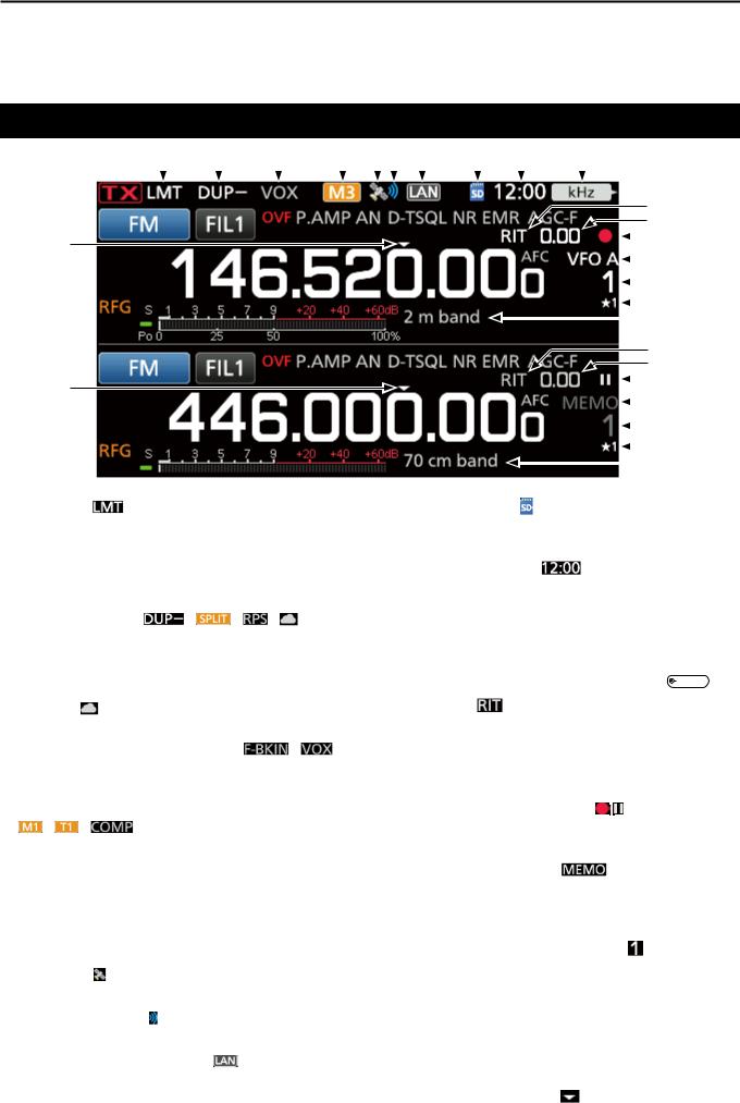
q LMT ICON |
|
|
|
|
|
|
|
|
i SD CARD ICON (p 6-1) |
|||||||||||||||||||
Displayed if the power amplifi er temperature |
|
|
|
|
|
Displayed when an SD card is inserted, and blinks |
||||||||||||||||||||||
becomes extremely high, and the Protection |
|
|
|
|
|
while accessing the SD card. |
||||||||||||||||||||||
function is activated after transmitting continuously |
|
|
o CLOCK READOUT |
|
(p 8-7) |
|||||||||||||||||||||||
for a long period of time. |
|
|
|
|
|
|
|
|
|
|||||||||||||||||||
|
|
|
|
|
|
|
|
|
Displays the current local time. |
|||||||||||||||||||
w DUPLEX/SPLIT/REPEATER MODE/INTERNAL |
|
|
|
|
|
|||||||||||||||||||||||
|
|
|
|
|
Touch the readout to display both the current local |
|||||||||||||||||||||||
GATEWAY ICONS / / / |
|
|
|
|
|
time and UTC time. |
|
|
|
|
|
|
|
|
|
|
|
|||||||||||
Displays “DUP” when the Duplex mode is ON. |
|
|
|
|
!0 FUNCTION INDICATOR FOR MULTI-FUNCTION |
|||||||||||||||||||||||
Displays “SPLIT” when the Split function is ON. |
|
|
|
|
||||||||||||||||||||||||
|
|
|
|
|
CONTROL |
|
|
|
|
|
|
|
|
|
|
|
|
|
|
|||||||||
Displays “RPS” while using the Repeater Simplex |
|
|
|
|
|
|
|
|
|
|
|
|
|
|
|
|
|
|
|
|||||||||
|
|
|
|
|
Displays the function that is assigned to MULTI . |
|||||||||||||||||||||||
mode (RPS) in the DD mode. |
|
|
|
|
|
|
|
|
|
|||||||||||||||||||
|
|
|
|
|
|
|
|
!1 RIT ICON |
(p 4-1) |
|
|
|
|
|
|
|
|
|
|
|
||||||||
Displays “ ” while using the Internal Gateway |
|
|
|
|
|
|
|
|
|
|
|
|
|
|
|
|||||||||||||
function. |
|
|
|
|
|
|
|
|
|
Displayed when the RIT function is ON. |
||||||||||||||||||
e BK-IN/F-BKIN/VOX INDICATORS / |
|
|
|
|
!2 RIT/DUPLEX OFFSET FREQUENCY READOUT |
|||||||||||||||||||||||
Displayed while the Semi Break-in, Full Break-in or |
|
|
|
Displays the shift offset frequency for the RIT or |
||||||||||||||||||||||||
VOX function is ON. |
|
|
|
|
|
|
|
|
|
Duplex functions, while these functions are ON. |
||||||||||||||||||
r M1~M8/T1~T8/SPEECH COMPRESSOR ICONS |
|
|
!3 VOICE RECORDER ICONS / |
|||||||||||||||||||||||||
/ / |
|
|
|
|
|
|
|
|
|
|
Displayed while recording or pausing the Voice |
|||||||||||||||||
Displays “M1”~“M8” while “External Keypad” on the |
|
|
|
recorder. |
|
|
|
|
|
|
|
|
|
|
|
|
|
|
|
|
||||||||
CONNECTORS screen is set to ON and you are |
|
|
|
|
!4 VFO/MEMORY ICONS |
|
(p 3-1) |
|||||||||||||||||||||
using the Memory Keyer function (p. 4-14). |
|
|
|
|
|
|||||||||||||||||||||||
|
|
|
|
|
Displays “VFO A” or “VFO B” when the VFO |
|||||||||||||||||||||||
Displays “T1”~“T8” while using the Voice TX |
|
|
|
|
|
|||||||||||||||||||||||
|
|
|
|
|
mode is selected, and displays “MEMO” when the |
|||||||||||||||||||||||
memory. |
|
|
|
|
|
|
|
|
|
|||||||||||||||||||
|
|
|
|
|
|
|
|
|
Memory mode is selected. |
|||||||||||||||||||
Displays “COMP” when the Speech Compressor |
|
|
|
|
|
|||||||||||||||||||||||
|
|
|
|
|
|
|
|
|
|
|
|
|
|
|
|
|
|
|
|
|
|
|
||||||
function is ON. |
|
|
|
|
|
|
|
|
!5 MEMORY CHANNEL READOUT |
|||||||||||||||||||
t GPS ICON |
|
|
|
|
|
|
|
|
|
Displays the selected memory channel number. |
||||||||||||||||||
|
|
|
|
|
|
|
|
|
|
|
|
|
|
|
|
|
|
|
|
|
|
|
|
|
|
|
||
Displays the status of the connected GPS receiver. |
|
|
!6 SELECT MEMORY CHANNEL ICON |
|||||||||||||||||||||||||
y GPS ALARM ICON |
|
|
|
|
|
|
|
|
|
Indicates that the displayed memory channel is |
||||||||||||||||||
|
|
|
|
|
|
|
|
|
assigned as a Select Memory channel ( 1~ 3). |
|||||||||||||||||||
Displayed when the GPS Alarm function is ON. |
|
|
|
|
|
|||||||||||||||||||||||
|
|
|
|
!7 MEMORY NAME (p 4-8) |
||||||||||||||||||||||||
u NETWORK CONTROL ICON |
|
|
|
|
|
|
|
|
||||||||||||||||||||
|
|
|
|
|
|
|
|
|
Displayed when the Memory name is entered. |
|||||||||||||||||||
Displayed while the transceiver and the optional |
|
|
|
|
|
|||||||||||||||||||||||
|
|
|
|
|
|
|
|
|
|
|
|
|
|
|
|
|
|
|
|
|
|
|
||||||
RS-BA1 are connected through a LAN cable for |
|
|
|
|
!8 QUICK TUNING ICON |
|
|
|
|
|
|
|
|
|
|
|
||||||||||||
Remote control operation. |
|
|
|
|
|
|
|
|
|
Displayed when the Quick Tuning Step function is |
||||||||||||||||||
|
|
|
|
|
|
|
|
1-4 ON. |
|
|
|
|
|
|
|
|
|
|
|
|
|
|
|
|
||||
PANEL DESCRIPTION |
1 |
|
!9 |
@0 |
@1 @2 |
|
@3 @4 |
|
@5 |
|
|
|
|
|
|
|
|||||||
|
|
|
|
|
|
|
|
|
|
||||||||||||
|
|
|
|
||||||||||||||||||
#3 |
|
|
|
|
|
|
|
|
|
|
|
|
|
|
|
|
|
|
|
|
1 |
#2 |
|
|
|
|
|
|
|
|
|
|
|
|
|
|
|
|
|
|
|
|
|
#1 |
|
|
|
|
|
|
|
|
|
|
|
|
|
|
|
@6 |
|
||||
#0 |
|
|
|
|
|
|
|
|
|
|
|
|
|
|
|
||||||
|
|
|
|
|
|
|
|
|
|
|
|
|
|
||||||||
|
|
|
|
|
|
|
|
|
|
|
|
|
|
|
|
|
|
|
|
|
|
@9 |
|
|
|
|
|
|
|
|
|
|
|
|
!9 |
|
|||||||
|
|
|
|
|
|
|
|
|
|
|
|
|
|||||||||
@8 |
|
|
|
|
|
|
|
|
|
|
|
|
|
|
@0 |
|
|||||
|
|
|
|
|
|
|
|
|
|
|
|
|
|
|
|||||||
@7 |
|
|
|
|
|
|
|
|
|
|
|
|
|
@1 |
|
||||||
|
|
|
|
|
|
|
|
|
|
|
|
|
|
|
|
|
|
|
|||
|
|
|
|
|
|
|
|
|
|
|
|
|
|
||||||||
|
|
|
|
|
|
|
|
|
|
|
|
@2 |
|
||||||||
#2 |
|
|
|
|
|
|
|
|
|
|
|
|
|
|
@3 |
|
|||||
|
|
|
|
|
|
|
|
|
|
|
|
|
|
||||||||
|
|
|
|
|
|
|
|
|
|
|
@4 |
|
|||||||||
|
|
|
|
|
|
|
|
|
|
|
|
|
|||||||||
#1 |
|
|
|
|
|
|
|
|
|
|
|
|
|
|
|
|
@5 |
|
|||
|
|
|
|
|
|
|
|
|
|
|
|
|
|||||||||
#0 |
|
|
|
|
|
|
|
|
|
|
|
@6 |
|
||||||||
@9 |
|
|
|
|
|
|
|
|
|
|
|
|
|
|
|
|
|
|
|
|
|
@8 |
|
|
|
|
|
|
|
|
|
|
|
|
|
|
|
|
|
|
|
|
|
@7 |
|
|
|
|
|
|
|
|
|
|
|
|
|
|
|
|
|
|
|
|
|
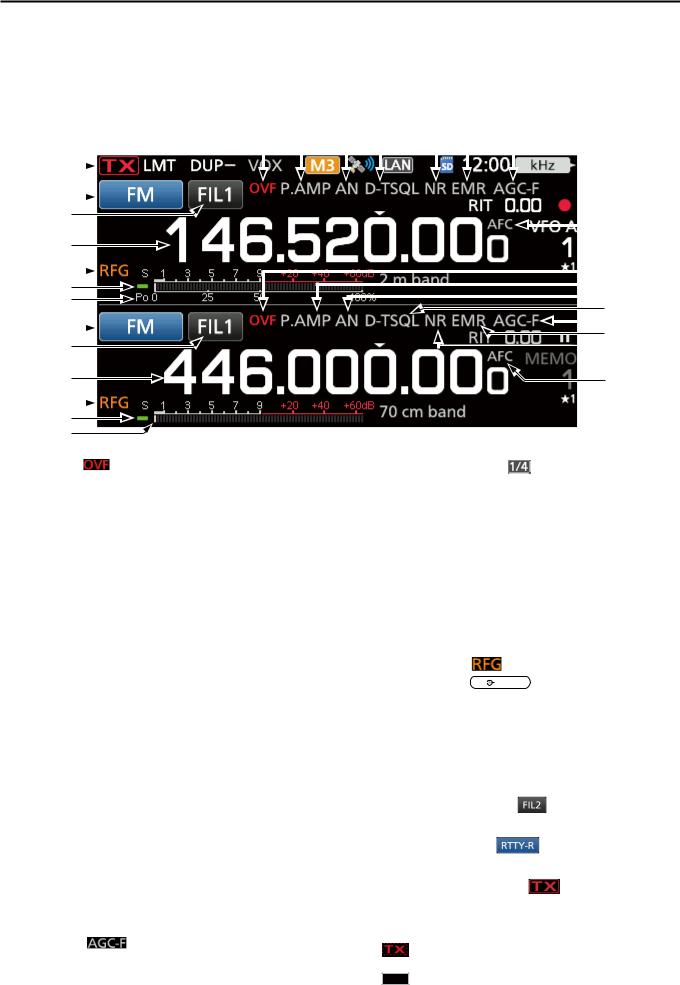
!9OVF ICON
Displayed when an excessively strong signal is received.
@0 PREAMPLIFIER/ATTENUATOR ICONS
 /
/
Displayed when one the Preamplifi ers is ON, or the
Attenuator is ON.
@1 NOTCH INDICATOR
Displays “AN” when the Auto Notch function is ON, and “MN” is displayed when the Manual Notch function is ON.
@2 NOISE BLANKER/TONE/DIGITAL SQUELCH
ICONS  /
/
Displayed when the Noise Blanker function is ON, when various tone functions are ON, or when various digital squelch functions are ON.
@3 NOISE REDUCTION/AUTO TUNE INDICATORS
Displays “NR” when the Noise Reduction function is
ON.
Displays “AUTOTUNE” when the Auto Tuning function is ON.
@4 EMR/BK/PACKET LOSS/AUTO REPLAY ICONS
 /
/ /
/ /
/
Displayed when the EMR (Enhanced Monitor Request) function is ON, when the BK (Break-in) function is ON, when Packet loss has occured, or when the Automatic Reply function is ON.
@5 AGC ICON (p 3-9)
Displayed while the Auto Gain Control (AGC) is ON.
@6 AFC/1 4 ICON  / (p 8-5)
“ ” is displayed while the Auto Frequency Control (AFC) is ON.
“ ” is displayed while the 1/4 Tuning function is ON. (p. 3-5)
@7 MULTI-FUNCTION METER (p 3-11)
Displays various values and levels, depending on the function that you selected.
@8 RX STATUS INDICATOR
Lights green when a signal is received, or the squelch is open.
@9 RF GAIN ICON |
|
(p 3-10) |
Displayed when AF |
|
RF/SQL (outer) is set to the |
|
counterclockwise from the 11 o’clock position. The icon indicates that the RF gain is reduced.
#0 MAIN BAND FREQUENCY READOUT
SUB BAND FREQUENCY READOUT (p 3-4)
Displays the transmit or receive frequency for the Main and Sub bands.
#1 IF FILTER INDICATOR (p 4-4)
Displays the selected IF fi lter number.
#2 MODE INDICATOR |
(p 3-3) |
Displays the selected operating mode.
#3 TX STATUS INDICATOR
Displays the transmit status of the displayed frequency.
• is displayed while transmitting.
•is displayed when the selected frequency is outside of the band edge frequency range.
•TX is displayed when transmission is inhibited (p. 3-10)
1-5

1 PANEL DESCRIPTION
Touch panel (Continued) |
|
DDFUNCTION screen |
DDMENU screen |
Function
name 
Selected 
value
Lights blue when active
zzPush FUNCTION to open the FUNCTION screen in the selected mode.
LTo close the FUNCTION screen, push EXIT . LTouching q or w at the bottom of the screen selects
Function screen 1 or 2.
FUNCTION screen list
*1 Touch for 1 second to select the function.
*2 Touch for 1 second to open its function menu.
P.AMP/ATT |
AGC*2 |
NOTCH*2 |
NB*2 |
OFF |
FAST |
OFF |
OFF |
P.AMP |
MID |
AN |
ON |
ATT*1 |
SLOW |
MN |
|
NR*2 |
IP+ |
VOX*2 |
BKIN*2 |
OFF |
OFF |
OFF |
OFF |
ON |
ON |
ON |
BKIN |
|
|
|
F-BKIN |
|
|
|
|
COMP*2 |
|
TONE*2 |
|
OFF |
OFF |
DTCS |
DTCS (T)/TSQL (R) |
ON |
TONE |
DTCS (T) |
TONE (T)/TSQL (R) |
|
TSQL |
TONE (T)/DTCS (R) |
|
D.SQL*2 |
TBW |
1/4 |
MONI*2 |
OFF |
WIDE |
OFF |
OFF |
DSQL |
MID |
ON |
ON |
CSQL |
NAR |
|
|
|
|
|
|
DUP*2 |
EXP P.AMP |
RPS |
TX PWR LIMIT*2 |
OFF |
OFF |
OFF |
OFF |
DUP– |
ON |
ON |
ON |
DUP+ |
|
|
|
zzPush MENU to open the MENU screen on the selected band.
LTo close the MENU screen, push EXIT .
LTouching q or w on the bottom of the screen selects MENU screen 1 or 2.
DDQUICK MENU
zzPush QUICK to open the QUICK MENU screen.
1-6

DDMulti-function menus
 Rotate
Push
Touch the edge to turn ON or OFF
Multi-function menu 
zzOpen the Multi-function menu by pushing  MULTI (Multi-function control).
zzOpen special menus by holding down VOX/BK-IN , NB , NR , or NOTCH for 1 second.
zzWhile the Multi-function menu is open, touch the desired item and rotate  MULTI to set the desired value.
Multi-function menu items
*1 Touch the edge to turn the function ON or OFF, or when you want to adjust.
*2 Touch the item for 1 second to enable  MULTI .
SSB |
SSB-D |
|
CW |
|
RTTY |
|
*2 |
RF POWER |
*2 |
RF POWER |
*2 |
RF POWER |
*2 |
RF POWER |
|
|
|
|||
MIC GAIN*2 |
MIC GAIN*2 |
KEY SPEED*2 |
TPF*1 |
|
||
COMP*1, *2 |
|
|
CW PITCH*2 |
|
|
|
MONITOR*1, *2 |
MONITOR*1, *2 |
|
|
MONITOR*1, *2 |
||
FM/AM/DV |
DD |
|
NB |
|
|
NR |
|
|
|
*2 |
RF POWER |
*2 |
LEVEL |
*2 |
LEVEL |
*2 |
|
RF POWER |
|
|
|
|
||||
MIC GAIN |
*2 |
*1 |
DEPTH |
*2 |
|
|
||
|
TX INHIBIT |
|
|
|
|
|||
|
|
|
|
WIDTH*2 |
|
|
||
MONITOR*1, *2 |
|
|
|
|
|
|
|
|
NOTCH |
VOX |
BK-IN |
TX PWR LIMIT |
||
*2 |
*2 |
DELAY |
*2 |
RF POWER |
*2 |
POSITION |
GAIN |
|
|
||
WIDTH*1 |
ANTI VOX*2 |
|
|
LIMIT |
|
|
DELAY*2 |
|
|
|
|
|
VOICE DELAY |
*1 |
|
|
|
|
|
|
|
|
|
PANEL DESCRIPTION |
1 |
Multi-function dial
|
|
|
|
|
When the Multi-function menu is closed, MULTI |
can |
1 |
||
|
||||
be enabled to adjust functions that are either on the |
|
|||
|
||||
upper right three keys or in the Multi-function menus. |
|
|||
The function is displayed in the upper right edge of the |
|
|||
screen. |
|
|
||
|
|
Function indicator for |
MULTI |
|
|
|
|
||
*1 You can independently enable  MULTI to adjust the function for the MAIN and SUB bands.
*2 On the Multi-function menus, touch the item for 1 second to assign the function to  MULTI .
Indicator |
|
Action |
|
RIT*1 |
Rotate |
Adjusts the RIT frequency. |
|
Hold down |
Clears the RIT frequency. |
||
|
|||
kHz*1 |
Changes the operating frequency on the kHz |
||
|
steps. |
|
|
M-CH*1 |
Selects Memory channels. |
||
Using the DR function, selects an individual |
|||
|
station or preset repeater. |
||
PBT1*1 |
Rotate |
Adjusts the Shift value for PBT1. |
|
Hold down |
Clears the Twin PBT setting. |
||
|
|||
PBT2*1 |
Rotate |
Adjusts the Shift value for PBT2. |
|
Hold down |
Clears the Twin PBT setting. |
||
|
|||
|
|
|
|
RF PWR*2 |
Adjusts the transmit output power. |
||
MIC G*2 |
Adjusts the microphone gain. |
||
COMP*2 |
Adjusts the Speech Compressor level. |
||
MONI*2 |
Adjusts the audio level for the Monitor function. |
||
SPEED*2 |
Sets the Key speed. |
||
PITCH*2 |
Sets the CW pitch. |
||
NB LEV*2 |
Adjusts the Noise Blanker level. |
||
NB DEP*2 |
Adjusts the DEPTH (Noise attenuation level). |
||
NB WID*2 |
Adjusts the WIDTH (Blanking duration time). |
||
NR LEV*2 |
Adjusts the transmit output power. |
||
NOTCH*2 |
Adjusts the Notch frequency. |
||
VOX G*2 |
Adjusts the VOX gain. |
||
*2 |
Adjusts the ANTI VOX level. |
||
A-VOX |
|||
*2 |
Adjusts the VOX delay time. |
||
VOX D |
|||
BKIN D*2 |
Adjusts the Break-in delay time. |
||
1-7

1 PANEL DESCRIPTION
Keyboard entering and editing
DDEntering and editing characters
You can enter and edit the items in the following table.
Menu |
Category |
Item |
Selectable characters |
Maximum |
|
characters |
|||||
|
|
|
|
||
SET |
My Station |
My Call Sign (DV)/(DD) |
A to Z, 0 to 9, (space), / |
8+4 |
|
|
|
TX Message (DV) |
A to Z, a to z, 0 to 9, (space), ˽ ! " # $ % & ' ( ) * + |
20 |
|
|
|
|
, - . / : ; < = > ? @ [ \ ] ^ _ ` { } ~ |
||
|
|
|
|
||
|
Network |
Network Name |
A to Z, a to z, 0 to 9, ! " # $ % & ( ) + , - . ; = @ [ ] ^ |
15 |
|
|
|
|
_ ` { } ~ |
||
|
|
|
|
||
|
|
Network User 1/2 ID |
A to Z, a to z, 0 to 9, ˽ ! " # $ % & ' ( ) * + , - . / : ; < = |
16 |
|
|
|
Network User 1/2 Password |
> ? @ [ \ ] ^ _ ` { } ~ |
16 |
|
|
|
|
••Password: Minimum 8 characters |
||
|
|
|
|
||
|
|
Network Radio Name |
A to Z, a to z, 0 to 9, (space), ˽ ! " # $ % & ' ( ) * + |
16 |
|
|
|
|
, - . / : ; < = > ? @ [ \ ] ^ _ ` { } ~ |
||
|
|
|
|
||
|
Time Set |
NTP Server Address |
A to Z, a to z, 0 to 9, - . |
64 |
|
|
SD Card |
Save Setting |
A to Z, a to z, 0 to 9, (space), ˽ ! " # $ % & ' ( ) * + |
|
|
|
|
Export |
, - . / : ; < = > ? @ [ ] ^ _ ` { } ~ |
20 |
|
|
|
|
••Illegal characters: / : ; * < > \ | |
|
|
MEMORY |
|
Memory Name |
A to Z, a to z, 0 to 9, (space), ˽ ! " # $ % & ' ( ) * + |
16 |
|
|
|
|
, - . / : ; < = > ? @ [ \ ] ^ _ ` { } ~ |
||
|
|
|
|
||
KEYER |
|
Keyer Memory |
A to Z, 0 to 9, (space), / ? ^ . , @ |
70 |
|
|
|
|
••“*” (asterisk) has its unique use. |
||
|
|
|
|
||
DECODE |
|
RTTY Memory |
A to Z, 0 to 9, (space), ! $ & ? " ' - / . , : ; ( ) |
70 |
|
VOICE |
|
VOICE TX RECORD |
A to Z, a to z, 0 to 9, (space), ˽ ! " # $ % & ' ( ) * + |
16 |
|
|
|
|
, - . / : ; < = > ? @ [ \ ] ^ _ ` { } ~ |
||
|
|
|
|
||
CS |
|
UR, R1, R2 |
A to Z, 0 to 9, (space), / |
8 |
|
DV/DD |
Your Call Sign |
NAME |
A to Z, a to z, 0 to 9, (space), ˽ ! " # $ % & ' ( ) * + |
16 |
|
MEMORY |
|
|
, - . / : ; < = > ? @ [ \ ] ^ _ ` { } ~ |
||
|
|
|
|||
|
|
CALL SIGN |
A to Z, 0 to 9, (space), / |
8 |
|
|
Repeater List |
GROUP NAME, NAME |
A to Z, a to z, 0 to 9, (space), ˽ ! " # $ % & ' ( ) * + |
16 |
|
|
|
|
, - . / : ; < = > ? @ [ \ ] ^ _ ` { } ~ |
||
|
|
|
|
||
|
|
SUB NAME |
A to Z, a to z, 0 to 9, (space), ˽ ! " # $ % & ' ( ) * + |
8 |
|
|
|
|
, - . / : ; < = > ? @ [ \ ] ^ _ ` { } ~ |
||
|
|
|
|
||
|
|
CALL SIGN, GW CALL SIGN |
A to Z, 0 to 9, (space), / |
8 |
|
DV GW |
Internal Gateway |
Gateway Repeater |
A to Z, a to z, 0 to 9, - . |
64 |
|
|
Settings |
(Server IP/Domain) |
|
||
|
|
|
|||
|
|
Terminal/AP, Call Sign, |
A to Z, 0 to 9, (space) |
8 |
|
|
|
Allowed Call Sign List |
|
||
|
|
|
|
||
GPS |
GPS TX Mode |
Unproto Address |
A to Z, a to z, 0 to 9, ˽ ! " # $ % & ' ( ) * + , - . / : ; < |
56 |
|
|
|
|
= > ? @ [ \ ] ^ _ ` { } ~ |
|
|
|
|
|
••Normally 12 characters |
|
|
|
|
Object Name, Item Name |
A to Z, a to z, 0 to 9, ˽ ! " # $ % & ' ( ) * + , - . / : ; < = |
9 |
|
|
|
|
> ? @ [ \ ] ^ _ ` { } ~ |
|
|
|
|
Comment |
A to Z, a to z, 0 to 9, ˽ ! " # $ % & ' ( ) * + , - . / : ; < = |
43 |
|
|
|
|
> ? @ [ \ ] ^ _ ` { } ~ |
|
|
|
|
|
••Maximum characters you can enter differs, depending |
|
|
|
|
|
on the data extension and altitude settings. |
|
|
|
|
GPS Message |
A to Z, a to z, 0 to 9, (space), ˽ ! " # $ % & ' ( ) * + |
20 |
|
|
|
|
, - . / : ; < = > ? @ [ \ ] ^ _ ` { } ~ |
|
|
|
GPS Memory |
GROUP NAME, NAME |
A to Z, a to z, 0 to 9, (space), ˽ ! " # $ % & ' ( ) * + |
16 |
|
|
|
|
, - . / : ; < = > ? @ [ \ ] ^ _ ` { } ~ |
|
|
DTMF |
DTMF MEMORY |
|
0 to 9, A B C D * # |
24 |
|
|
SEND |
Direct Input |
0 to 9, A B C D * # |
24 |
|
DR |
TO SELECT |
Direct input (UR)/(RPT) |
A to Z, 0 to 9, (space), / |
8 |
|
|
|
|
1-8 |
|

DDKeyboard types
You can select the Full Keyboard or Tenkey pad in
“Keyboard Type” on the FUNCTION screen. (p. 8-4)
MENU » SET > Function > Keyboard Type
LYou can also temporarily switch in the QUICK MENU by pushing QUICK .
LYou can select the full keyboard layout in “Full Keyboard
Layout” on the FUNCTION screen. (p. 8-4)
MENU » SET > Function > Full Keyboard Layout
DDEntering and editing
PANEL DESCRIPTION |
1 |
1
Moves the cursor backward |
|
|
|
Moves the cursor forward |
||||
|
|
|||||||
|
|
|
|
|
|
|
|
Clears the entered character |
|
|
|
|
|
|
|
|
|
|
|
|
|
|
|
|
|
Selects the character type |
|
|
|
|
|
|
|
|
|
Enters an uppercase letter |
|
|
|
|
|
Saves the entry |
||
|
|
|||||||
|
|
|
|
|||||
Selects alphabet mode |
|
|
|
|
|
Cancels entry and returns to the |
||
|
|
|||||||
or number mode |
|
previous screen |
||||||
 Enters a space
Alphabet mode 
Number mode 
Symbol mode 
1-9
1 PANEL DESCRIPTION
Keypad entering and editing (Continued)
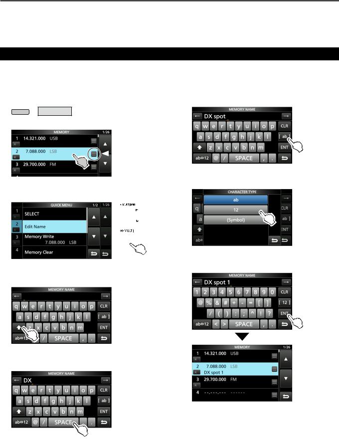
DDEntering and editing example
Entering “DX spot 1” in the Memory channel 2
1.Open the MEMORY screen.
MENU » MEMORY
2.Touch memory channel 2 for 1 second.
You can also open the  QUICK MENU by touching this key.
••Opens the QUICK MENU.
3. Select “Edit Name.”
 Rotate
 Push
Push
••Opens the MEMORY NAME screen.
4. Touch [ ], and then touch [D].
9. Touch [ab].
••Opens the entry CHARACTER TYPE screen.
10. Touch [12].
11.Touch [1].
12.Touch [ENT] to save the entry.
5.Touch [ ] again, and then touch [X].
6.Touch [SPACE].
••Returns to the previous screen.
••Enters a space.
7.Touch [s], [p], [o], and then [t].
8.Touch [SPACE].
••Enters a space.
1-10
INSTALLATION AND CONNECTIONS 2
Selecting a location
Select a location for the transceiver that allows adequate air circulation, free from extreme heat, cold or vibration, and other electromagnetic sources.
Never place the transceiver in areas such as: ••Temperatures below –10°C (+14°F) or above +60°C (+140°F).
••An unstable place that slopes or vibrates. ••In direct sunlight.
••High humidity and temperature environments. ••Dusty environments.
••Noisy environments.
Using the desktop stands
The transceiver has a stand for desktop use.
Stand
NOTE: DO NOT hold the stand, dials and controls when you carry the transceiver. This may damage them.
Heat dissipation
••DO NOT place the transceiver against walls or put anything on top of the transceiver. This may block
airflow and overheat the transceiver. 2
••NEVER install the transceiver in a place without adequate ventilation. Heat dissipation may be reduced, and the transceiver may be damaged. ••DO NOT touch the transceiver after transmitting
continuously for long periods of time. The transceiver may become hot.
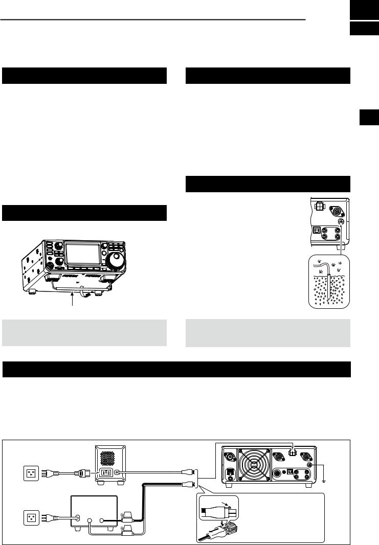
Grounding
To prevent electrical shock, television interference (TVI), broadcast interference (BCI) and other problems, ground the transceiver using the ground terminal [GND] on the rear panel.
For best results, connect a heavy gauge wire or strap to a long ground rod. Make the distance between the [GND] terminal and ground as short as possible.
RWARNING! NEVER connect the [GND] terminal to a gas or electric pipe, since the connection could cause an explosion or electric shock.
Connecting an external DC power supply
Confirm that the transceiver is OFF before connecting the DC power cable.
LWe recommend using Icom’s optional PS-126
(DC 13.8 V/25 A) power supply, when available.
LWhen connecting a non-Icom DC power cable, the transceiver needs:
••DC 13.8 V (Capacity: At least 18 Amps)
••A power supply with an over current protective line, and low voltage fluctuation or ripple.
PS-126 |
|
PS-126 |
|
|
|
|
|
|
|
|
|
||
AC cable |
|
|
DC power cable |
|
|
|
Non-Icom DC power supply |
|
|
Supplied DC |
|
IC-9700 |
GND |
DC 13.8 V/18 A |
Fuses |
power cable |
Locking tab |
When disconnecting, firmly |
|
|
or more |
Black |
|
|
push down the locking tab, |
|
|
+ |
_ |
|
|
|
and then pull the connector |
|
|
|
|
|
w q |
out of the socket. |
|
|
|
Red |
|
|
|
|
2-1

3 BASIC OPERATION
When first applying power
Before turning ON your transceiver for the first time, make sure all connections are correctly made.
After all connections are made, set the dials to the positions described below.
Maximum counterclockwise
AF
 RF/SQL
12 oʼclock position |
|
AF |
RF/SQL |
TIP: When you turn OFF the transceiver, it memorizes the current settings. Therefore, when you turn ON the transceiver again, it restarts with the same settings.
Turning power ON or OFF
zzTo turn ON the transceiver, push POWER .
zzTo turn OFF the transceiver, hold down POWER for
1 second until “POWER OFF...” is displayed.
Selecting the VFO and Memory modes
VFO mode
Set the desired frequency by rotating MAIN DIAL .
Memory mode
Enter contents into the desired channel in the MEMORY list.
Call channel mode
Call channels (or Main channel) are used to call on an often used frequency. A Call channel is assigned on each band.
Selecting the VFO mode or Memory mode
zzPush V/M to select the VFO or Memory mode. zzPush CALLDR to select the Call channel mode.
VFO mode (Example: VFO A)
CALLDR
V/M
V/M |
Call Channel mode |
|
(Example: Call channel 1) |
Memory mode (Example: Memory channel 1)
Adjusting the volume level
Rotate AF
 RF/SQL (inner) to adjust the volume level.
Using the VFO mode
The IC-9700 has 2 Variable Frequency Oscillators
(VFO), “A” and “B.” Having 2 VFOs is convenient to quickly select 2 frequencies, or for split frequency operation (p. 4-9). You can use either of the VFOs to operate on a frequency and mode.
DDSelecting VFO A or VFO B
Push A/B to select the VFO A or VFO B.
A/B
VFO A |
VFO B |
DDEqualizing VFO A and VFO B
You can set the displayed VFO’s frequency to the VFO that is not displayed.
Hold down A/B until 2 short beeps sound.
3-1

Dualwatch operation
Dualwatch simultaneously monitors two frequencies. The IC-9700 has 2 independent receiver circuits, the Main and Sub bands, so that you can use Dualwatch with no compromises, even on different bands and modes.
LThe same frequency cannot be set to the both Main and Sub bands.
Hold down OFF for 1 second to turn the Dualwatch function ON or OFF.
Hold down for 1 second.
BASIC OPERATION |
3 |
Selecting the Main and Sub bands
The IC-9700 has 2 identical receivers, Main and Sub. The Main band is displayed on the upper half of the screen, and the Sub band is displayed on the lower half.
LSome functions can only be applied to the selected band,
and you can transmit on only the Main band (except in 3 Split Frequency operation).
To select the Main band or Sub band, touch the grayed frequency readout.
••The selected band’s frequency readout is displayed clearly, and the frequency of the non-selected band is grayed.
DDSwapping the Main band and Sub band
Hold down M/S for 1 second.
Hold down for 1 second.
3-2

3 BASIC OPERATION
Selecting the operating band
Do the following steps to change the operating band.
Also, the band stacking register provides 3 memories for each band key to store frequencies and operating modes. This function is convenient to quickly recall previously operated frequencies and modes on the selected band.
DDUsing the band stacking registers
Follow the steps below to enter a register on the selected band.
1.Touch the MHz digits. (Example: 146)
••Opens the BAND STACKING REGISTER screen.
2.Touch a band key. (Example: 1295 MHz)
LThe same band cannot be set to both Main and Sub bands.
BAND STACKING REGISTER screen
TIP: Selecting a different Register
••Touching the band key for 1 second changes between the 3 Registers.
••Touch  to return to the previous screen.
Selecting the operating mode
You can select between the SSB (LSB/USB), SSB data (LSB-DATA/USB-DATA), CW, CW reverse, RTTY, RTTY reverse, AM, AM data (AM-DATA), FM, FM data (FM-DATA), DV and DD* modes.
*Only for the 1200 MHz band
1.Touch the mode icon (example: FM).
••Opens the MODE screen.
2.On the MODE screen, touch the desired mode key. (Example: SSB).
LIn the SSB, AM or FM modes, the [DATA] key is displayed.
••Operating mode selection list
LTouch mode key to select the operating mode.
Mode key |
Operating mode |
||
[SSB] |
USB |
|
LSB |
[CW] |
CW |
|
CW-R |
[RTTY] |
RTTY |
|
RTTY-R |
[AM] |
|
AM |
|
[FM] |
|
FM |
|
[DV] |
|
DV |
|
[DD] |
|
DD |
|
|
LSB |
|
LSB-D |
[DATA] |
USB |
|
USB-D |
AM |
|
AM-D |
|
|
|
||
|
FM |
|
FM-D |
Selecting the Data mode
You can operate data communications (SSTV, RTTY
(AFSK), PSK31, JT65B and FT8).
LWhen a data mode is selected, you can mute the input from the microphone.
MENU » SET > Connectors > MOD Input > DATA MOD
3-3
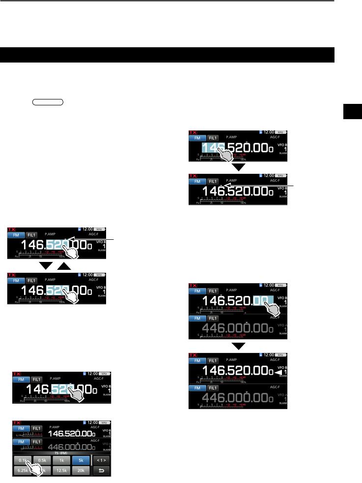
Setting the frequency
DDUsing the Main Dial
1.Select the desired operating band. (p. 3-3) (Example: 145 MHz)
2.Rotate MAIN DIAL .
••The frequency changes according to the selected Tuning Step.
L is displayed when you set an amateur radio frequency, and
  (with dotted line) is displayed when you set a frequency outside the Ham band, or outside your set Band Edges.
DDAbout the Tuning Step function
You can set the  ’s tuning step for each operating mode.
Touch the kHz digits to turn the Tuning Step function ON or OFF.
L The Tuning Step function's icon “▼” is displayed above the 1 kHz digit.
The Tuning Step function is ON.
BASIC OPERATION |
3 |
DDAbout the 1 MHz Step Tuning function
You can use the maximum tuning step of 1 MHz.
Touch the MHz digits for 1 second to turn the MHz
Step Tuning function ON or OFF. 3 LWhen using the [UP]/[DN] keys on the microphone,
the frequency changes in 1 MHz steps.
The MHz Step function is ON.
DDAbout the 1 Hz step Fine Tuning
function
You can use the minimum tuning step of 1 Hz for fine tuning in the SSB, CW and RTTY modes.
Touch the Hz digits for 1 second to turn the Fine Tuning function ON or OFF.
DDChanging the Tuning Step
When the Tuning Step function is ON, you can change the tuning steps for each operating mode.
1.Select the desired operating mode. (p. 3-3)
(Example: FM)
2.Touch the kHz digit for 1 second.
••The TS (FM) screen is displayed.
3.Touch the desired tuning step. (Example: 0.1 k)
••The tuning step is set and returns to the previous screen.
 The 1 Hz digit is displayed.
LWhen using the [UP]/[DN] keys on the microphone, the frequency changes in 50 Hz steps with the Fine Tuning function ON or OFF.
3-4

3 BASIC OPERATION
Setting the frequency (Continued)
DDAbout the 1/4 Tuning function
Mode: SSB-D/CW/RTTY
With the Tuning Function OFF, turn ON the 1⁄4 Tuning function to reduce the tuning speed to 1⁄4 of the normal speed, for finer tuning.
1.Push FUNCTION .
••Opens the FUNCTION screen.
2.Touch [1/4].
FUNCTION screen
3. Push EXIT .
 1/4 Tuning
function
DDDirectly entering a frequency
You can set the frequency without rotating MAIN DIAL by directly entering it on the keypad.
Entering the operating frequency
1.Touch the MHz digits. (Example: 146)
••Opens the BAND STACKING REGISTER screen.
2.Touch [F-INP].
••Opens the F-INP screen.
3. Start entry with the most significant digit.
DDAbout the Auto Tuning Step function
The tuning step automatically changes, depending on the rotating speed of MAIN DIAL .
LYou can change the Auto Tuning Step function settings in the following menu. (p. 8-4)
MENU » SET > Function > MAIN DIAL Auto TS
LTo clear the entry, touch [CE].
LTo clear the entry and return to the previous screen, push EXIT .
4.Touch [ENT] to set the entered frequency.
••Closes the F-INP screen.
LIf you touch [ENT] when the digits under 100 kHz are not entered, “0” will be automatically entered into the digits that are blank.
Entry examples
••144.680 MHz: [1], [4], [4], [•(−)], [6], [8], [0], [ENT] ••145.000 MHz: [1], [4], [5], [ENT]
••Changing from 144.680 MHz to 144.540 MHz: [•(− )], [5], [4], [0], [ENT]
3-5
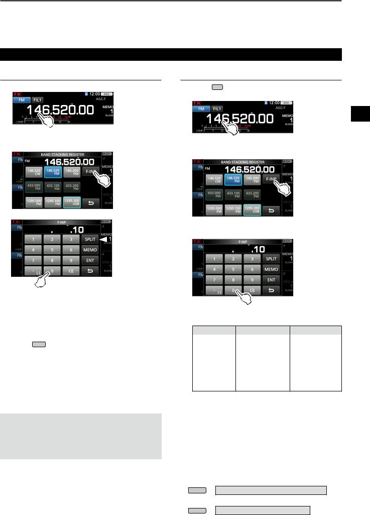
Setting the frequency (Continued)
Entering the Split Frequency Offset
1.Touch the MHz digits. (Example: 146)
••Opens the BAND STACKING REGISTER screen.
2.Touch [F-INP].
••Opens the F-INP screen.
 [SPLIT] or [-SPLIT] is displayed
3.Enter the Split Frequency Offset.
LIf you want the minus shift direction, touch [•(−)]. LEnter the offset between −9.999 MHz and +9.999
MHz (1 kHz steps).
LTo clear the entry, touch [CE].
LTo clear the entry and return to the previous screen, push EXIT .
LAfter entering, the Split function is automatically turned ON.
4.To save the entry, touch [SPLIT] or [−SPLIT].
••Closes the F-INP screen.
Entry examples
••5 kHz: |
[5], [SPLIT] |
••−10 kHz: |
[•(−)], [1], [0], [−SPLIT] |
NOTE:
If the entered operating frequency is out of an amateur band’s frequency range, the transmit frequency is automatically set to the band edge frequency.
BASIC OPERATION |
3 |
Selecting a Memory channel by number
1.Touch V/M to select the Memory mode.
2.Touch the MHz digits. (Example: 146)
3
••Opens the BAND STACKING REGISTER screen.
3.Touch [F-INP].
••Opens the F-INP screen.
4.Enter a Memory channel number. (Example: 10)
LIf you want to set the Program Scan Edge channel or
Call channel, enter between “100” ~ “107.”
Channel type Channel number Number to enter
|
1A |
100 |
|
Programming |
1B |
101 |
|
2A |
102 |
||
Scan Edge |
2B |
103 |
|
|
3A |
104 |
|
|
3B |
105 |
|
Call channel |
C1 |
106 |
|
C2 |
107 |
||
|
5.Touch [MEMO] to select the memory channel of entered number .
••Closes the F-INP screen.
••The selected memory channel contents are displayed.
DDBand Edge Beep
You will hear a Band Edge Beep and  will be displayed when you tune into or out of an amateur band’s frequency range.
LYou can change the Band Edge Beep settings in the following menu.
MENU » SET > Function > Band Edge Beep
LIf the Beep Level item is set to “0%,” no beep sounds.
MENU » SET > Function > Beep Level
3-6

3 BASIC OPERATION
Setting the frequency (Continued)
DDEntering a Band Edge
When “ON (User)” or “ON (User) & TX Limit” is selected on the “Band Edge Beep” screen, you can enter a total of 30 band edge frequency pairs.
LInitially, all Ham band frequencies are entered into the first 3 band edges. Therefore, you must first edit or delete them to enter a new band edge.
LYou cannot enter an overlapping frequency, or a frequency that is out of the preset Ham band frequencies.
LBand edges are entered from the lower frequency first.
1. Open the “Band Edge Beep” screen.
MENU » SET > Function > Band Edge Beep
2.Select “ON (User)” or “ON (User) & TX Limit.”
LIf you select “ON (User) & TX Limit,” you can limit transmission to within the entered frequency range.
 Rotate
 Push
Push
3. Select “User Band Edge.”
 Rotate
 Push
Push
••Opens the “User Band Edge” screen.
Editing a Band Edge
You can edit a band edge entered as a default or when entering a new band edge.
1.On the FUNCTION set screen, select “User Band
Edge.”
2.Touch the band edge you want to edit for 1 second.
(Example: 2: 430.000.000 – 440.000.000 MHz)
 Rotate
 Push
Push
3.Edit the lower band edge frequency, then touch [ENT].
(Example: 430.1)
Entry example: [•], [1], [ENT]
4.Edit the upper band edge frequency, then touch
[ENT]. (Example: 439.1)
Entry example: [4] [3] [9][•], [9], [ENT]
••The edited band edge is saved and returns to the previous screen.
TIP:
You can also edit the frequency by rotating MAIN DIAL or
 MULTI .
3-7

Setting the frequency
DDEntering a Band Edge (Continued)
Deleting a Band Edge
To enter a new band edge, first you must delete a preset band edge.
1.On the FUNCTION set screen, select “User Band
Edge.”
2.Touch the desired band edge to delete for 1 second.
(Example: 3: 1260.000.000 – 1300.000.000 MHz)
3.Touch “Delete.”
••The selected band edge is deleted and returns to the previous screen.
BASIC OPERATION |
3 |
Entering a new Band Edge |
|
|
After you delete or edit the preset band edges, you |
|
|
can enter a new band edge. |
|
|
|
|
|
1. On the FUNCTION set screen, select “User Band |
3 |
|
Edge.” |
|
|
2. Select a blank band. (Example: 5) |
|
|
 Rotate
 Push
Push
3.Enter the lower band edge frequency, then touch [ENT]. (Example: 430.1)
Entry example: [4] [3] [0][•] [1] [ENT]
4.Enter the upper band edge frequency, then touch [ENT]. (Example: 439.9)
Entry example: [4] [3] [9] [•] [9] [ENT]
••The entered band edge is saved and returns to the previous screen.
3-8

3 BASIC OPERATION
Setting the frequency
DDEntering a Band Edge (Continued)
Inserting a Band Edge
After you delete or edit the preset band edges, follow the steps below to insert a band edge.
1.On the FUNCTION set screen, select “User Band
Edge.”
2.Touch the band edge you want to insert a new band edge above for 1 second.
(Example: 3: 1261.000.000–1300.000.000 MHz)
LThe new band edge will be inserted above the selected band edge.
3.Touch “Insert.”
Resetting all band edges to presets
The steps below will reset all the band edges to their initial settings. All entered settings will be deleted.
1.Open the “User Band Edge” screen.
2.Touch any band edge for 1 second.
3.Touch “Default.”
••Displays “Reset All Edges?”
4. Touch [YES].
4.Enter the lower band edge frequency then touch [ENT]. (Example: 430.1)
Entry example: [4] [3] [0][•] [1] [ENT]
••All the band edges reset to the initial settings.
5.Enter the upper band edge frequency, then touch [ENT]. (Example: 439.9)
Entry example: [4] [3] [9] [•] [9] [ENT]
••The entered band edge is saved and returns to the previous screen.
3-9

RF gain and SQL level
Rotate AF
 RF/SQL (outer) to adjust the RF gain and SQL level.
By default, rotating left (when set to the 12 o’clock position) adjusts the RF gain, and rotating right adjusts the squelch level, as described below.
Noise squelch (FM/DV mode)
Squelch is open |
Maximum RF gain |
|
|
||
RF gain |
S-meter squelch |
|
adjustable range |
||
adjustable range |
||
|
is displayed |
Maximum S-meter |
|
Minimum RF gain |
||
squelch |
RF gain
Adjust the RF gain to decrease the noise received from a nearby strong station.
••Rotate counterclockwise to reduce the RF gain, which reduces the receive sensitivity. “RFG” appears when
AF
 RF/SQL is set to the counterclockwise from the 11 o’clock position. “RFG” indicates that the RF gain is reduced.
LIf a strong signal is received and “OVF” (Overflow) appears, reduce the RF gain until “OVF” disappears.
SQL level
There are 2 types of SQL levels, depending on the operating mode.
••Noise squelch
Rotate the AF
 RF/SQL (outer) until the noise just disappears and the TX/RX indicator goes OFF.
••S-meter squelch
The S-meter squelch disables the audio output from the speaker or headphones when the received signal is weaker than the specified S-meter squelch level.
Rotate the AF
 RF/SQL clockwise from the 12 o’clock position to increase the S-meter threshold level.
LYou can change the AF
 RF/SQL (outer) control type in
“RF/SQL Control.” (p. 3-10)
MENU » SET > Function > RF/SQL Control
Dial Lock function
The Dial Lock function prevents frequency changes caused by accidently moving MAIN DIAL .
LThis function electronically locks the dial.
Hold down SPEECH for 1 second to turn the
Dial Lock function ON or OFF.
••During Split Frequency operation, the Split |
Hold down |
Lock function may be turned ON. (p. 4-10) |
MENU » SET > Function > Lock Function
3-10
BASIC OPERATION |
3 |
Adjusting the transmit output power
Before transmitting, monitor your selected operating |
|
frequency to make sure you do not cause interference to other |
|
stations on the same frequency. It is good amateur practice |
|
to listen first, and then, even if nothing is heard, ask if the |
3 |
frequency in use once or twice, before you start operating. |
DDAdjusting the transmit output power
1.Select the operating mode. (p. 3-3) (Example: USB)
2.Touch the meter to display the Po meter. (p. 3-11)
3.Open the Multi-function menu.
|
Push |
4. Push TRANSMIT or hold down [PTT]. |
|
••The Po meter level changes according |
|
to your voice level in the SSB mode. |
|
••The TX/RX indicator lights red and |
|
is displayed. |
Lights red |
5.Touch “RF POWER.”
6.Adjust the transmit output power to between 0 and
100%.
••The Po meter displays the RF output power in a percentage. It becomes the S-meter while receiving.
7.Push TRANSMIT or release [PTT].
••Returns to receive.
Transmit Power Limit function
The Transmit Power Limit function limits the output power to the preset level for each band.
1.On the FUNCTION set screen, touch [TX PWR LIMIT].
••Each touch turns the function ON or OFF.
2.Touch [TX PWR LIMIT] for 1 second.
3.Rotate  MULTI to set the maximum transmit power.
4.Push  MULTI to close the MENU.
 Set transmit power
 Limited transmit power (LIMIT value)
 Even when set RF POWER exceeds
“LIMIT,” the actual output power is limited to this value.
 Loading...