


 Loading...
BASIC MANUAL
HF/50 MHz TRANSCEIVER
i7610
Thank you for choosing this Icom product. The IC-7610 HF/50 MHz TRANSCEIVER is designed and built with Icom’s state of the art technology and craftsmanship. With proper care, this product should provide you with years of trouble-free operation. We appreciate you making the IC-7610 your transceiver of choice, and hope you agree with Icom’s philosophy of “technology first.” Many hours of research and development went into the design of your IC-7610.
IMPORTANT
READ ALL INSTRUCTIONS carefully completely before using the transceiver.
SAVE THIS INSTRUCTION MANUAL— This instruction manual contains basic operating instructions for the IC7610. For the advanced operating instructions, see the Advanced Manual on the supplied CD.
FEATURES
••RF Direct Sampling System
The IC-7610 employs an RF direct sampling system. RF signals are directly converted to digital data and processed in the FPGA. This system is a leading technology marking an epoch in amateur radio.
••2 identical receivers
The IC-7610 has 2 independent receiver circuits for the Main and Sub bands.
••A built-in DIGI-SEL unit
Both the Main and Sub receivers have built-in DIGI-SEL (digital preselector) units. These reject interfering signals.
••Real-Time Spectrum Scope
Displays the Main and Sub band conditions. It provides class-leading performance in resolution, sweep speed and provides a 100 dB dynamic range.
••A built-in automatic antenna tuner
••Multi-function control for easy settings
••Extra large 7 inch touch screen color display
••External monitor connection with a DVI-D port
••BNC type RX IN/OUT connectors
••Class Leading RMDR and Phase Noise
Characteristics
••IP remote control capability with the optional
RS-BA1 ip remote control software
••Remote encoder capability with the optional
RC-28 remote encoder
••Dualwatch operation
Icom is not responsible for the destruction, damage to, or performance of any Icom or non-Icom equipment, if the malfunction is because of:
••Force majeure, including, but not limited to, fires, earthquakes, storms, floods, lightning, or other natural disasters, disturbances, riots, war, or radioactive contamination.
••The use of Icom transceivers with any equipment that is not manufactured or approved by Icom.
i
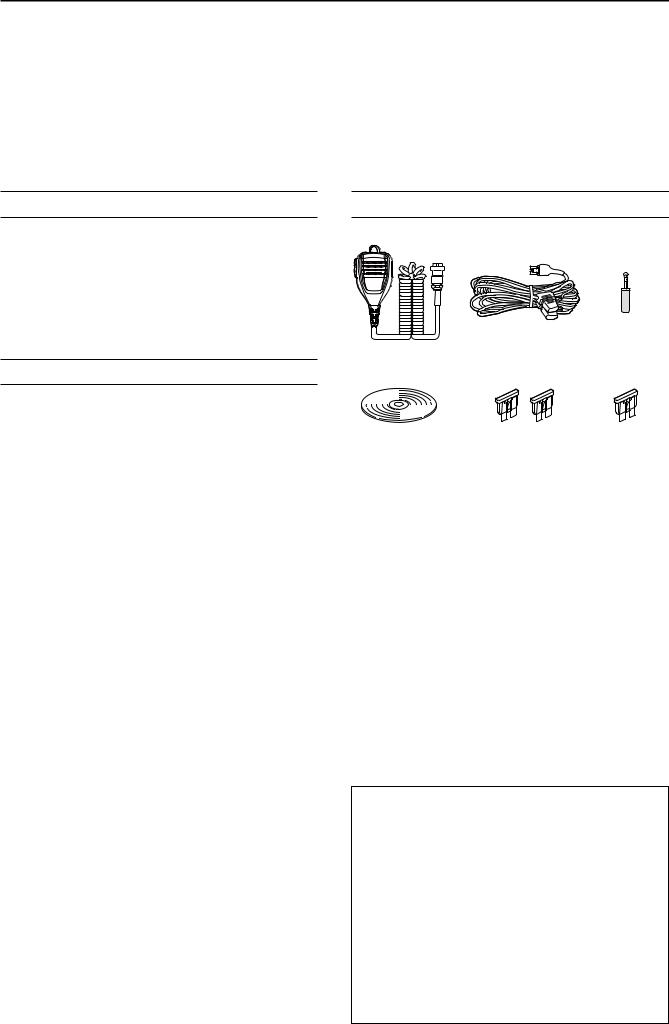
SUPPLIED ACCESSORIES
|
DC power cable |
CW key plug |
|
|
(6.35 mm: 1/4" Stereo) |
||
Hand microphone |
(3 m: 9.8 ft) |
||
|
|||
|
|
||
(HM-219) |
|
|
|
CD |
Spare fuse |
Spare fuse |
|
(30 A) |
(5 A) |
||
|
LDifferent types of accessories may be supplied, or may not be supplied depending on the transceiver version.
This product includes RTOS “RTX” software, and is licensed according to the software license.
This product includes “zlib” open source software, and is licensed according to the open source software license.
This product includes “libpng” open source software, and is licensed according to the open source software license.
Refer to the Text files in the License folder of included CD for information on the open source software being used by this product.

FCC INFORMATION
This equipment has been tested and found to comply with the limits for a Class B digital device, pursuant to part 15 of the FCC Rules. These limits are designed to provide reasonable protection against harmful interference in a residential installation. This equipment generates, uses and can radiate radio frequency energy and, if not installed and used in accordance with the instructions, may cause harmful interference to radio communications. However, there is no guarantee that interference will not occur in a particular installation. If this equipment does cause harmful interference to radio or television reception, which can be determined by turning the equipment off and on, the user is encouraged to try to correct the interference by one or more of the following measures:
••Reorient or relocate the receiving antenna. ••Increase the separation between the equipment
and receiver.
••Connect the equipment into an outlet on a circuit different from that to which the receiver is connected.
••Consult the dealer or an experienced radio/TV technician for help.
WARNING: MODIFICATION OF THIS DEVICE TO RECEIVE CELLULAR RADIOTELEPHONE SERVICE SIGNALS IS PROHIBITED UNDER FCC RULES AND FEDERAL LAW.
CAUTION: Changes or modifications to this device, not expressly approved by Icom Inc., could void your authority to operate this device under FCC regulations.
TRADEMARKS
Icom, Icom Inc. and the Icom logo are registered trademarks of Icom Incorporated (Japan) in Japan, the United States, the United Kingdom, Germany, France, Spain, Russia, Australia, New Zealand and/or other countries.
Microsoft, Windows and Windows Vista are registered trademarks of Microsoft Corporation in the United States and/or other countries.
Adobe, Acrobat, and Reader are either registered trademarks or trademarks of Adobe Systems Incorporated in the United States and/or other countries.
All other products or brands are registered trademarks or trademarks of their respective holders.
EXPLICIT DEFINITIONS
WORD |
DEFINITION |
|
R DANGER! |
Personal death, serious injury or an |
|
explosion may occur. |
||
|
||
R WARNING! |
Personal injury, fire hazard or electric |
|
shock may occur. |
||
|
||
CAUTION |
Equipment damage may occur. |
|
|
Recommended for optimum use. No |
|
NOTE |
risk of personal injury, fire or electric |
|
|
shock. |
ABOUT SPURIOUS SIGNALS
Spurious signals may be received near the following frequencies. These are made in the internal circuit and does not indicate a transceiver malfunction:
• 28.671 MHz |
• 50.516 MHz |
• 51.881 MHz |
• 53.246 MHz |
• 53.760 MHz |
|
ABOUT CE AND DOC
Hereby, Icom Inc. declares that the versions of IC-7610 which have the
“CE” symbol on the product, comply with the essential requirements of the Radio Equipment Directive, 2014/53/EU, and the
restriction of the use of certain hazardous substances in electrical and electronic equipment Directive, 2011/65/EU. The full text of the EU declaration
of conformity is available at the following internet address:
http://www.icom.co.jp/world/support
DISPOSAL
The crossed-out wheeled-bin symbol
on your product, literature, or packaging reminds you that in the
European Union, all electrical and electronic products, batteries, and accumulators (rechargeable batteries)
must be taken to designated collection locations at the end of their working life. Do not dispose of these products as unsorted municipal waste.
Dispose of them according to the laws in your area.
ii

ABOUT THE TOUCH SCREEN
DD Touch operation
In the Full manual or Basic manual, the touch operation is described as shown below.
Touch
If the display is touched briefly, one short beep sounds.
Touch for 1 second
If the display is touched for 1 second, one short and one long beep sound.
DD Touch screen precautions
••The touch screen may not properly work when the
LCD protection film or sheet is attached. ••Touching the screen with your finger nails, sharp topped object and so on, or touching the screen
hard may damage it.
••Tablet PC’s operations such as flick, pinch in and pinch out cannot be performed on this touch screen.
DD Touch screen maintenance
••If the touch screen becomes dusty or dirty, wipe it clean with a soft, dry cloth.
••When you wipe the touch screen, be careful not to push it too hard or scratch it with your finger nails.
Otherwise you may damage the screen.
ABOUT THE SUPPLIED CD
The following items are included on the CD.
••Basic manual (English)
Instructions for basic operations, the same as this manual.
••Advanced manual (English)
Instructions for advanced operations in English.
••Basic manual (Multi-language)
Instructions for basic operations in multiple languages.
••Schematic diagram
Includes the schematic and block diagrams.
••HAM radio Terms (English)
A glossary of HAM radio terms in English.
••Adobe® Acrobat® Reader® Installer
Installer for Adobe® Acrobat® Reader®.
To read the manuals or Schematic diagram, Adobe® Acrobat® Reader® is required. If you have not installed it, please install the Adobe Acrobat Reader on the CD or download it from Adobe Systems Incorporated’s website.
A PC with the following Operating System is required. ••Microsoft® Windows® 10
••Microsoft® Windows® 8.1 ••Microsoft® Windows® 7
Starting the CD
1.Insert the CD into the CD drive.
2.Double click “Menu.exe” on the CD.
••Depending on the PC setting, the menu screen shown below is automatically displayed.
3.Click the desired button to open the file.
LTo close the Menu screen, click [Quit].
Opens the English |
Opens the English |
Basic manual (this manual) |
Advanced manual |
Opens the |
|
|
Opens the |
|
multi-language |
|
|
|
Schematic |
|
|
|
||
Basic manual |
|
|
diagram |
|
Opens the
Glossary
Installs Adobe® Acrobat® |
Closes the Menu screen |
Reader® |
|
LDifferent types of menu screen may be displayed, depending on the transceiver version.
iii

ABOUT THE CONSTRUCTION OF THE MANUAL
There are two different types of manuals for this transceiver, the Basic manual (this manual) and the Advanced manual.
DD Basic manual (This manual)
Instructions for the basic operations, precautions, installations and connections.
DD Advanced manual (PDF type)
Instructions for the advanced operations, such as listed below and more...
LThe Advanced manual is on the CD that is supplied with the transceiver, or can be downloaded from the Icom website. http://www.icom.co.jp/world/support
••User Band Edge ••IP Plus function
••Main/Sub Band Tracking function ••Adjusting the Drive Gain level ••VOX function
••∂TX function
••Operating CW <Advanced> ••Operating RTTY (FSK) and PSK ••Data mode (AFSK) operation ••Scope operation <Advanced> ••Voice Recorder functions ••Voice TX Memory operation
••Using an SD card and USB flash drive <Advanced>
••Memory operation ••Scan
••Set mode <Advanced> ••Clock and Timers <Advanced> ••Updating the firmware
••Replacing fuse ••Cleaning
And more....
iv
ABOUT THE INSTRUCTIONS
The Basic and Advanced manuals are described in the following manner.
“ ” (Quotation marks):
Used to indicate icons, setting items, and screen titles displayed on the screen.
The screen titles are also indicated in uppercase letters. (Example: FUNCTION screen)
[ ] (brackets):
Used to indicate keys.
Routes in the set modes and setting screens
Routes in the set mode, setting screen and the setting items are described in the following manner.
MENU » SET > Time Set > Date/Time
Instruction example
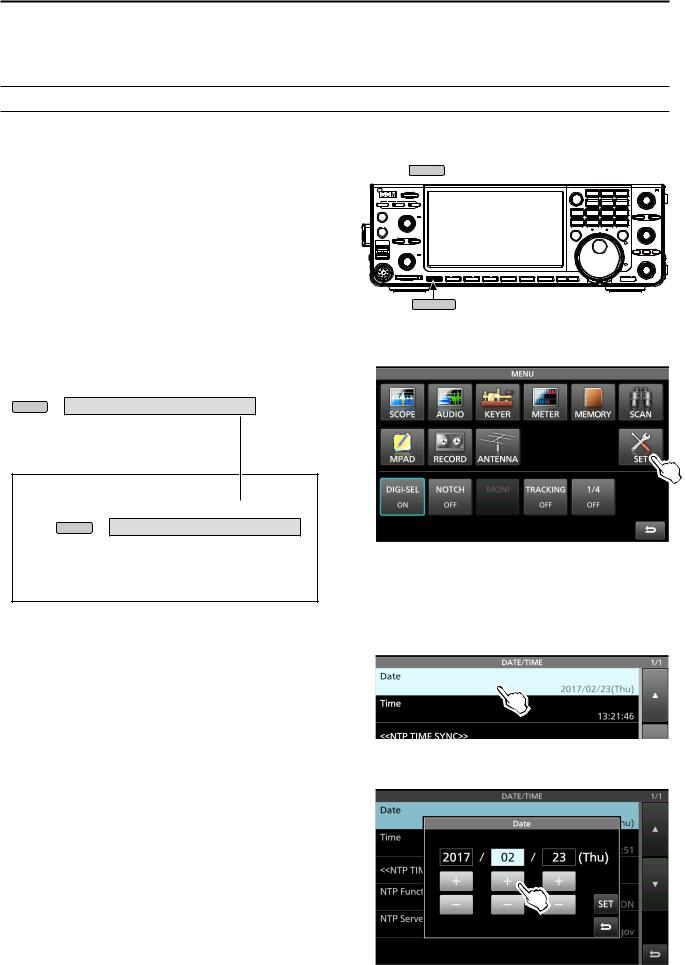
DD Setting the current date
1.Open the DATE/TIME screen.  MENU » SET > Time Set > Date/Time
2.Touch “Date/Time.”
3.Touch “Date.”
••Opens the date editing screen.
v
Detailed instruction
1. Push MENU .
MENU
••Opens the MENU screen.
2. Touch [SET].
••Opens the SET screen.
3.Touch “Time Set.”
••Opens the TIME SET screen.
4.Touch “Date/Time.”
••Opens the DATE/TIME screen.
5.Touch “Date.”
••Opens the date editing screen.
6.Touch [+] and [-] to set the date.
7.Touch [SET] to set the date.
LTouch  to cancel.
••Returns to the previous screen.

TABLE OF CONTENTS
IMPORTANT............................................................... |
i |
FEATURES................................................................. |
i |
SUPPLIED ACCESSORIES........................................ |
i |
FCC INFORMATION................................................... |
ii |
TRADEMARKS........................................................... |
ii |
EXPLICIT DEFINITIONS............................................ |
ii |
DISPOSAL.................................................................. |
ii |
ABOUT CE AND DOC................................................ |
ii |
ABOUT THE TOUCH SCREEN................................. |
iii |
ABOUT THE SUPPLIED CD...................................... |
iii |
ABOUT THE CONSTRUCTION OF THE MANUAL...iv
ABOUT THE INSTRUCTIONS................................... |
v |
|
PRECAUTIONS....................................................... |
viii |
|
1. |
PANEL DESCRIPTION..................................... |
1-1 |
|
Front panel........................................................ |
1-1 |
|
Rear panel........................................................ |
1-3 |
|
Touch screen display........................................ |
1-4 |
|
DDMENU screen.............................................. |
1-6 |
|
DDMulti-function menus................................... |
1-6 |
|
DDMulti-function key group.............................. |
1-7 |
|
DDQUICK MENU............................................. |
1-7 |
|
Keyboard entering and editing.......................... |
1-8 |
|
DDKeyboard types........................................... |
1-8 |
|
DDEntering and editing.................................... |
1-8 |
|
DDEntering and editing example..................... |
1-9 |
2. |
INSTALLATION AND CONNECTIONS............ |
2-1 |
|
Using the desktop stands.................................. |
2-1 |
|
Selecting a location........................................... |
2-1 |
|
Heat dissipation................................................ |
2-1 |
|
Grounding......................................................... |
2-1 |
|
Connecting an external DC power supply ........ |
2-1 |
|
Connecting the antenna tuner........................... |
2-2 |
|
Connecting a Transverter.................................. |
2-2 |
|
Linear amplifier connections............................. |
2-3 |
|
DDConnecting the IC-PW1/IC-PW1EURO...... |
2-3 |
|
DDConnecting a non-Icom linear amplifier...... |
2-3 |
3. |
BASIC OPERATION......................................... |
3-1 |
|
When first applying power................................. |
3-1 |
|
Turning power ON or OFF................................ |
3-1 |
|
Adjusting the volume level................................ |
3-1 |
|
Selecting the VFO and Memory modes............ |
3-1 |
|
Selecting the Main and Sub bands................... |
3-2 |
|
DDSwitching the Main band and Sub band..... |
3-2 |
|
Dualwatch operation......................................... |
3-2 |
|
DDUsing the Dualwatch operation................... |
3-2 |
|
Selecting the operating band............................ |
3-3 |
|
DD Selecting the operating band |
|
|
on the keypad |
3-3 |
|
DDSelecting the operating band |
|
|
on the screen |
3-3 |
|
Selecting the operating mode........................... |
3-3 |
Setting the frequency........................................ |
3-4 |
DDUsing the Main Dial..................................... |
3-4 |
DDSetting the Tuning Step function................. |
3-4 |
DDChanging the Tuning Step.......................... |
3-4 |
DDUsing the 1 Hz step Fine Tuning function... |
3-4 |
DDUsing the 1/4 Tuning function..................... |
3-5 |
DDUsing the Auto Tuning Step function........... |
3-5 |
DDDirectly entering a frequency...................... |
3-5 |
Dial Lock function.............................................. |
3-6 |
RF gain and SQL level...................................... |
3-7 |
Meter display..................................................... |
3-7 |
DDSelecting the Meter readout........................ |
3-7 |
DDAbout the Multi-function meter.................... |
3-7 |
DDDisplaying the Multi-function meter............. |
3-8 |
Adjusting the transmit output power.................. |
3-8 |
DDAdjusting the transmit output power........... |
3-8 |
Adjusting the microphone gain.......................... |
3-9 |
Basic transmission............................................ |
3-9 |
4. RECEIVING AND TRANSMITTING................. |
4-1 |
Preamplifiers..................................................... |
4-1 |
Attenuator......................................................... |
4-1 |
RIT function....................................................... |
4-1 |
DDUsing the RIT Monitor function................... |
4-1 |
AGC function control......................................... |
4-2 |
DDSelecting the AGC time constant |
|
preset value |
4-2 |
DDSetting the AGC time constant.................... |
4-2 |
Using the Twin PBT........................................... |
4-3 |
Selecting the IF filter......................................... |
4-4 |
Selecting the IF filter shape.............................. |
4-4 |
Noise Blanker.................................................... |
4-5 |
DDAdjusting the NB level and time.................. |
4-5 |
Noise Reduction................................................ |
4-5 |
DDAdjusting the Noise Reduction level........... |
4-5 |
Digital Selector.................................................. |
4-6 |
DDTurning ON the Digital Selector function..... |
4-6 |
DDAdjusting the center frequency................... |
4-6 |
Notch Filter........................................................ |
4-6 |
DDSelecting the Notch function type............... |
4-6 |
DDAuto Notch function.................................... |
4-6 |
DDManual Notch function................................ |
4-7 |
Monitor function................................................ |
4-7 |
Speech Compressor (SSB)............................... |
4-8 |
Auto Tuning function (AM/CW)......................... |
4-8 |
Split frequency operation.................................. |
4-9 |
DDUsing the Quick Split function..................... |
4-9 |
DDUsing the receive and transmit frequencies |
|
set to Main and Sub |
4-9 |
Split Lock function........................................... |
4-10 |
Setting the transmit filter width........................ |
4-10 |
vi

TABLE OF CONTENTS (Continued)
|
Operating CW................................................. |
4-10 |
|
DDSetting the CW pitch control..................... |
4-10 |
|
DDSetting the keying speed.......................... |
4-11 |
|
DDUsing the Break-in function....................... |
4-11 |
|
DDMonitoring the CW side tone.................... |
4-12 |
|
DDAPF (Audio Peak Filter) operation............ |
4-12 |
|
DDAbout the Electronic Keyer function.......... |
4-13 |
5. |
SCOPE OPERATION....................................... |
5-1 |
|
Spectrum scope screen.................................... |
5-1 |
|
DDMarker......................................................... |
5-1 |
|
DDUsing the Spectrum Scope......................... |
5-1 |
|
DDDisplaying the Mini scope screen............... |
5-2 |
|
Audio scope screen.......................................... |
5-2 |
|
DDUsing the Audio scope................................ |
5-2 |
|
DDAUDIO SCOPE SET screen....................... |
5-3 |
6. SD CARD/USB FLASH DRIVE........................ |
6-1 |
|
|
About the SD cards........................................... |
6-1 |
|
About the USB flash drive................................. |
6-1 |
|
Saving data....................................................... |
6-1 |
|
Inserting............................................................ |
6-1 |
|
Formatting......................................................... |
6-2 |
|
DDFormatting the SD card or |
|
|
USB flash drive.......................................... |
6-2 |
|
Unmounting....................................................... |
6-2 |
7. |
ANTENNA TUNER OPERATION..................... |
7-1 |
|
About the Antenna memory settings................. |
7-1 |
|
DDThe Antenna memory screen...................... |
7-1 |
|
DDSaving an antenna connector setting......... |
7-1 |
|
DDSelecting the antenna type......................... |
7-2 |
|
About the internal antenna tuner....................... |
7-2 |
|
Using the Internal antenna tuner....................... |
7-3 |
|
DDManual tuning............................................. |
7-3 |
|
DDPTT Tuner start........................................... |
7-3 |
|
About an external antenna tuner....................... |
7-3 |
|
DDUsing the AH-4 or AH-740.......................... |
7-3 |
|
DDUsing an external antenna tuner................. |
7-4 |
|
Emergency mode (Tuner)................................. |
7-4 |
8. |
SET MODE....................................................... |
8-1 |
|
Set mode description........................................ |
8-1 |
|
DDEntering the Set mode................................ |
8-1 |
|
Tone Control/TBW ............................................ |
8-2 |
|
Function............................................................ |
8-2 |
|
Connectors........................................................ |
8-5 |
|
Network............................................................. |
8-7 |
|
Display.............................................................. |
8-8 |
|
Time Set............................................................ |
8-9 |
|
SD Card............................................................ |
8-9 |
|
USB Flash Drive............................................. |
8-10 |
|
Others............................................................. |
8-10 |
9. |
CLOCK AND TIMERS...................................... |
9-1 |
|
Setting the date and time.................................. |
9-1 |
|
DDSetting the date........................................... |
9-1 |
|
DDSetting the current time............................... |
9-1 |
|
DDSetting the UTC offset................................. |
9-1 |
|
DDDisplaying CLOCK2.................................... |
9-1 |
|
DDSetting the CLOCK2 UTC offset................. |
9-2 |
|
DDEditing the CLOCK2 name......................... |
9-2 |
10. |
MAINTENANCE............................................. |
10-1 |
|
Resetting......................................................... |
10-1 |
|
DDPartial reset............................................... |
10-1 |
|
DDAll reset..................................................... |
10-1 |
|
Troubleshooting.............................................. |
10-2 |
11. |
SPECIFICATIONS.......................................... |
11-1 |
|
DDGeneral..................................................... |
11-1 |
|
DDTransmitter................................................ |
11-1 |
|
DDReceiver.................................................... |
11-2 |
|
DDAntenna tuner........................................... |
11-2 |
12. |
OPTIONS........................................................ |
12-1 |
13. CONNECTOR INFORMATION....................... |
13-1 |
|
|
Interface information....................................... |
13-1 |
|
ACC sockets................................................... |
13-2 |
|
PHONES......................................................... |
13-3 |
|
ELEC-KEY...................................................... |
13-3 |
|
KEY................................................................. |
13-3 |
|
DC 13.8 V....................................................... |
13-3 |
|
TUNER............................................................ |
13-3 |
|
MIC................................................................. |
13-3 |
|
EXT KEYPAD.................................................. |
13-4 |
|
REMOTE......................................................... |
13-4 |
|
METER........................................................... |
13-4 |
|
USB port (type A)............................................ |
13-4 |
|
ALC................................................................. |
13-4 |
|
SEND.............................................................. |
13-4 |
|
LAN................................................................. |
13-5 |
|
EXT-DISPLAY................................................. |
13-5 |
|
USB 2.............................................................. |
13-5 |
|
USB 1.............................................................. |
13-5 |
|
EXT-SP A / EXT-SP B..................................... |
13-5 |
|
REF IN............................................................ |
13-5 |
|
X-VERTER...................................................... |
13-6 |
|
ANT 1 / ANT 2................................................. |
13-6 |
|
RX-ANT IN/OUT.............................................. |
13-6 |
INSTALLATION NOTES............................................. |
I |
|
INDEX........................................................................ |
II |
|
vii

PRECAUTIONS
R DANGER HIGH RF VOLTAGE! NEVER touch an antenna or antenna connector while transmitting. This could cause an electrical shock or burn.
R DANGER! NEVER operate the transceiver near unshielded electrical blasting caps or in an explosive atmosphere. This could cause an explosion and death.
R WARNING RF EXPOSURE! This device emits Radio Frequency (RF) energy. Extreme caution should be observed when operating this device. If you have any questions regarding RF exposure and safety standards please refer to the Federal Communications Commission
Office of Engineering and Technology’s report on
Evaluating Compliance with FCC Guidelines for Human Radio Frequency Electromagnetic Fields (OET Bulletin 65).
R WARNING! NEVER operate the transceiver with a headset or other audio accessories at high volume levels. If you experience a ringing in your ears, reduce the volume or discontinue use.
R WARNING! NEVER apply AC power to the [DC13.8V] socket on the transceiver rear panel. This could cause a fire or damage the transceiver.
R WARNING! NEVER apply more than 16 V DC to the [DC13.8V] socket on the transceiver rear panel. This could cause a fire or damage the transceiver.
R WARNING! NEVER reverse the DC power cable polarity. This could cause a fire or damage the transceiver.
R WARNING! NEVER remove the fuse holder on the DC power cable. Excessive current caused by a short could cause a fire or damage the transceiver.
R WARNING! NEVER let metal, wire or other objects contact the inside of the transceiver, or make incorrect contact with connectors on the rear panel. This could cause an electric shock or damage the transceiver.
R WARNING! NEVER operate or touch the transceiver with wet hands. This could cause an electric shock or damage to the transceiver.
R WARNING! NEVER operate the equipment if you notice an abnormal odor, sound or smoke. Immediately turn OFF the power and/or remove the DC power cable. Contact your Icom dealer or distributor for advice.
R WARNING! NEVER put the transceiver on an unstable place where the transceiver may suddenly move or fall. This could cause an injury or damage the transceiver.
R WARNING! NEVER operate the transceiver during a lightning storm. It may result in an electric shock, cause a fire or damage the transceiver. Always disconnect the power source and antenna before a storm.
CAUTION: DO NOT expose the transceiver to rain, snow or any liquids. They could damage the transceiver.
CAUTION: DO NOT change the internal settings of the transceiver. This may reduce transceiver performance and/ or damage the transceiver. The transceiver warranty does not cover any problems caused by unauthorized internal adjustments.
CAUTION: DO NOT install the equipment in a place without adequate ventilation, or block any cooling vents on the top, rear, sides or bottom of the transceiver or the cooling fan. Heat dissipation may be reduced and damage the transceiver.
CAUTION: DO NOT use harsh solvents such as benzine or alcohol when cleaning. This could damage the equipment surfaces. If the surface becomes dusty or dirty, wipe it clean with a soft, dry cloth.
CAUTION: DO NOT place or leave the transceiver in areas with temperatures below 0°C (32°F) or above 50°C (122°F).
CAUTION: DO NOT place the transceiver in excessively dusty environments, or in direct sunlight. This could damage the transceiver.
CAUTION: DO NOT set the transceiver’s RF output power to more than a connected linear amplifier’s maximum input level. Otherwise, the linear amplifier will be damaged.
CAUTION: DO NOT use non-Icom microphones. Other microphones have different pin assignments and may damage the transceiver.
BE CAREFUL! The transceiver will become hot when operating the transceiver continuously for long periods of time.
NEVER leave the transceiver in an insecure place to avoid use by unauthorized persons.
Turn OFF the transceiver’s power and disconnect the DC power cable when you will not use the transceiver for long period of time.
The LCD display may have cosmetic imperfections that appear as small dark or light spots. This is not a
malfunction or defect, but a normal characteristic of LCD displays.
viii

1 PANEL DESCRIPTION
Front panel
|
q |
|
w |
!2 |
|
e |
||
|
||
r |
o |
|
|
||
t |
!1 |
|
|
||
y |
!0 |
|
|
||
|
o |
|
u |
|
i |
q POWER KEY POWER (p. 3-1)
Turns the transceiver ON or OFF.
w TRANSMIT KEY TRANSMIT (p. 3-9)
Toggles between transmit and receive.
The TX/RX indicator
••Lights green while receiving. ••Lights red while transmitting.
e TIMER KEY TIMER
Turns the Sleep Timer or Daily Timer function ON or OFF.
r HEADPHONE JACK [PHONES] (p. 13-3)
Connects to standard stereo headphones.
tELECTRONIC KEYER JACK [ELEC-KEY] (p. 13-3)
Connects to a paddle to use the internal electronic keyer for the CW operations.
yUSB PORT [USB A] (p. 13-4)
Insert a USB flash drive, USB A type keyboard,
RC-28 remote encoder, mouse or hub.
uMICROPHONE CONNECTOR [MIC] (p. 13-3)
Connects to the supplied or an optional microphone.
iSD CARD SLOT [SD CARD] (p. 6-1)
Accepts an SD card. The indicator next to the slot lights blue when inserted.
o VOLUME CONTROL AF
 RF/SQL (p. 3-1)
LThe upper control is for the Main band, and the lower control is for the Sub band.
•Push to turn the Mute function ON or OFF.
-The TX/RX indicator lights orange when the Mute function is ON.
•Adjusts the audio output level.
RF GAIN/SQUELCH CONTROL AF
 RF/SQL (p. 3-7)
Adjusts the RF gain and squelch threshold levels.
!0NOISE REDUCTION KEY NR (p. 4-5)
Turns the Noise Reduction function ON or OFF.
!1NOISE BLANKER KEY NB (p. 4-5)
Turns the Noise Blanker ON or OFF.
!2 ANTENNA TUNER KEYTUNER (p. 7-3)
Turns the antenna tuner ON or OFF, or activates the tuner.
!3 !4 !5 !6 !7 !8 !9 @0@1 |
!3MENU KEYMENU (p. 8-1)
Displays the MENU screen.
!4MINI SCOPE KEY M.SCOPE (p. 5-2)
Displays the Mini Scope or Spectrum Scope.
!5MEMO PAD WRITE KEY MP-W
Saves the displayed contents into the Memo Pad.
!6MEMO PAD READ KEY MP-R
Sequentially calls up the contents in the Memo Pad.
!7 AUTO TUNE KEYAUTO TUNE (p. 4-8)
Automatically tunes the operating frequency to a received CW signal.
!8 QUICK KEYQUICK (p. 1-7)
Displays the QUICK MENU.
1-1
PANEL DESCRIPTION |
1 |
Front panel (Continued)
!9 |
|
EXIT |
@9 |
|
|
SPEECH |
|
|
1 |
|
|
EXIT KEY |
|
SPEECH/LOCK KEY |
|
|
|
||||
Exits a setting screen or returns to the previous |
••Announces the operating frequency and mode by |
|
||||||||
screen. |
|
pushing this key. |
|
|
|
|
||||
@0 VOICE MEMORY RECORD KEYREC |
••Electronically locks MAIN DIAL |
by holding down |
|
|||||||
this key for 1 second. |
|
|
|
|
||||||
Saves the previously received signal for the preset |
|
|
|
|
||||||
|
|
|
|
|
|
(p. 3-2) |
|
|||
time period set in REC Time, using the Instant |
#0 |
|
|
|
CHANGE |
|
||||
MAIN/SUB CHANGE KEY |
|
|
|
|||||||
Replay function, or starts recording a QSO audio |
Toggles the frequency, mode and selected memory |
|
||||||||
onto an SD card. |
channel between the Main and Sub band. |
|
||||||||
@1 VOICE MEMORY PLAY BACK KEYPLAY |
#1RIT/TX CONTROL RIT/ TX |
(p. 4-1) |
|
|||||||
Plays back the last 5 seconds of the Instant Replay |
Shifts the receive or transmit frequency up to |
|
||||||||
memory, or all of the Instant Replay memory. |
±9.99 kHz without changing the transmit or receive |
|
||||||||
|
|
|
frequency. |
TX |
|
|
|
|
||
|
|
|
#2 |
|
|
|
|
|
||
|
|
$0 |
TX KEY |
|
|
|
|
|
|
|
|
|
Turns the |
TX function ON or OFF. |
|
|
|||||
|
|
|
|
|
||||||
|
|
|
#3 |
|
|
CLEAR |
|
|
|
|
|
@2 |
#9 |
CLEAR KEY |
|
|
|
|
|
||
|
Clears the RIT or TX shift frequency. |
|
||||||||
|
|
#8 |
|
|||||||
|
@3 |
#4RIT KEY RIT |
(p. 4-1) |
|
|
|
|
|||
|
#7 |
|
|
|
|
|||||
|
@4 |
|
|
|
|
|||||
|
#6 |
Turns the Receiver Incremental Tuning (RIT) |
|
|||||||
|
@5 |
function ON or OFF. |
|
|
|
|
||||
|
|
#5 |
|
|
|
|
||||
|
|
#5KEY SPEED |
|
|
|
|
|
|||
|
@6 |
#4 |
KEY |
|
|
|
|
|||
|
SPEED PITCH CONTROL (p. 4-11) |
|
||||||||
|
|
#3 |
Adjusts the internal electronic CW keyer speed. |
|
||||||
|
|
#2 |
CW PITCH |
KEY |
|
|
|
|
||
|
|
|
SPEED PITCH CONTROL (p. 4-10) |
|
||||||
|
|
#1 |
Shifts the received CW audio pitch and the CW |
|
||||||
|
|
|
side tone pitch without changing the operating |
|
||||||
|
|
|
frequency. |
|
|
|
|
|
|
|
@7@8@9#0
@2MULTI-FUNCTION CONTROL  MULTI (p. 1-6)
Displays the Multi-function menu for various adjustments, or selects an item.
@3SPLIT KEY SPLIT (p. 4-9)
Turns the Split function ON or OFF.
@4DUALWATCH KEY DUAL-W (p. 3-2)
Turns the Dualwatch function ON or OFF.
@5GENERAL COVERAGE BAND KEY GENE
Selects the general coverage band.
@6TRANSMIT FREQUENCY CHECK KEY XFC
(p. 4-1, 4-9, 4-10)
Enables you to monitor the transmit frequency while holding it down in the Split mode.
@7TENSION ADJUSTER
Adjusts the friction of MAIN DIAL .
@8MAIN DIAL MAIN DIAL (p. 3-4)
Changes the operating frequency.
#6MAIN/SUB ACCESS KEY MAIN/SUB (p. 3-2)
Selects the Main or Sub band frequency readout. ••The selected band’s frequency is displayed clearly
whereas the non-selected band’s frequency is displayed in gray.
#7AUDIO PEAK FILTER/
TWIN PEAK FILTER KEY APF/TPF (p. 4-12)
In the CW mode, turns the Audio Peak Filter ON or OFF, and in the RTTY mode, turns the Twin Peak Filter ON or OFF.
#8FILTER KEY FILTER (p. 4-4)
Selects one of three IF filters.
#9TWIN PASSBAND TUNING CONTROL TWIN PBT CLR
(p. 4-3)
Adjusts the IF filter’s passband width.
$0KEYPAD 1.8 ~ 50
Selects the operating band by pushing once, or call up other stacked frequencies by pushing the same key several times.
1-2
1 |
PANEL DESCRIPTION |
|
|
|
|
|
|
Rear panel |
|
|
|
|
|
|
|
|
q |
w |
e |
r |
|
|
t |
|
!5 |
|
|
|
|
|
y |
|
|
|
|
!6!7!8!9 |
@0 |
|
|
|
|
|
|
|
u |
||
|
|
|
|
|
|
|
|
|
!4 !3 |
|
|
!2 |
!1 |
!0o |
i |
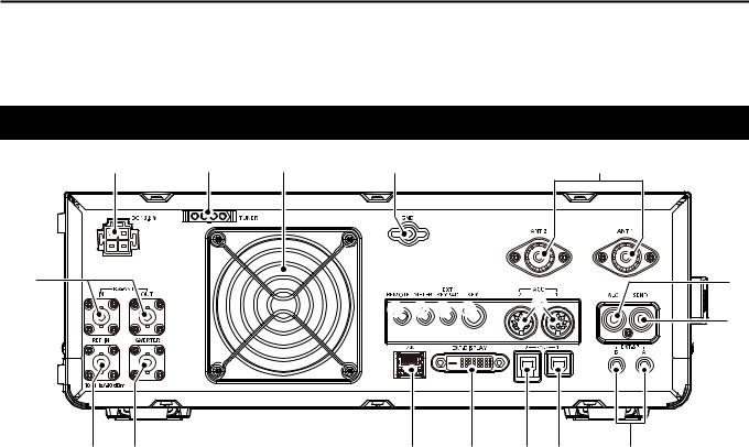
qDC POWER SOCKET [DC 13.8 V]
Connects to 13.8 V DC through the DC power cable.
wTUNER CONTROL SOCKET [TUNER]
Accepts the control cable from an optional AH-4 or AH-740 automatic antenna tuner.
eCOOLING FAN
Cools the PA unit when necessary.
rGROUND TERMINAL [GND]
Connects to ground to prevent electrical shocks, TVI, BCI and other problems.
tANTENNA CONNECTOR [ANT1]/[ANT2]
Connects to a 50 Ω antenna. If you use the AH-4 or
AH-740, you must connect the antenna to [ANT1].
yALC INPUT JACK [ALC]
Connects to the ALC output jack of a non-Icom linear amplifier.
uSEND CONTROL JACK [SEND]
Connects to control transmit with non-Icom external units.
iEXTERNAL SPEAKER JACK A/B [EXT-SP]
Accepts a 4 ~ 8 Ω external speaker.
oUSB PORT [USB 1] (Type B)
Connects to a PC for remote control operations.
!0USB PORT [USB 2] (Type B) For digital data input or output.
!1EXTERNAL DISPLAY CONNECTOR
[EXT-DISPLAY]
Connects to an external display monitor.
!2ETHERNET CONNECTOR [LAN]
Connects to a PC network through a LAN.
!3TRANSVERTER CONNECTOR [X-VERTER]
Connects to an external transverter for input/output.
!4REFERENCE SIGNAL INPUT [REF IN]
Input for a 10 MHz reference signal through the BNC connector.
!5RECEIVE ANTENA [RX ANT–IN]/[RX ANT–OUT]
Connects to an external unit, such as preamplifier or RF filter, using BNC connectors.
••This is located between the transmit/receive switching circuit and receiver’s RF stage.
!6CI-V REMOTE CONTROL JACK [REMOTE]
Connects to a PC or other transceiver for remote control.
!7METER JACK [METER]
Outputs received signal strength, transmit output power, VSWR, ALC, speech compression, Vd or Id levels for an external meter.
!8EXTERNAL KEYPAD JACK [EXT KEYPAD]
(p. 13-4)
Connects to an external keypad for direct voice memory, memory keyer, RTTY memory or PSK memory transmission.
!9STRAIGHT KEY JACK [KEY]
Connects to a straight key or external electronic keyer with 1/4 inch standard plug.
@0ACC SOCKET [ACC1]/[ACC2]
Connects to devices to control an external unit or to control the transceiver.
1-3
PANEL DESCRIPTION |
1 |
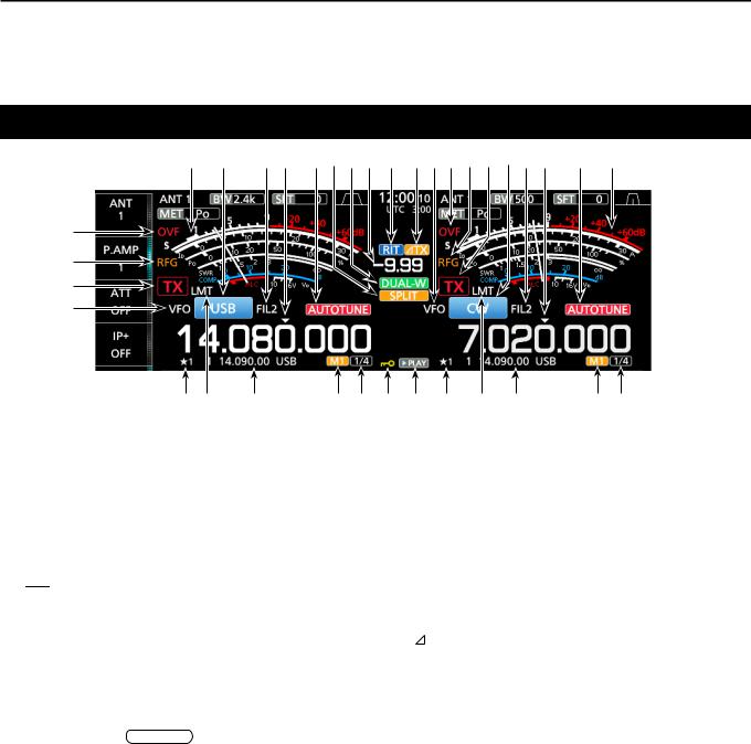
Touch screen display
|
|
|
|
|
|
|
|
|
|
|
|
|
|
|
|
|
|
|
q w e r |
t y u i o !0!1w e r |
t y u i |
1 |
|||||||||||||||
|
|
|
|
|
|
|
|
|
|
|
|
|
|
|
|
|
|
|
|
|
|
|
|
|
|
|
|
|
|
|
|
|
|
|
|
|
|
|
|
|
|
|
|
|
|
|
|
|
|
|
|
|
|
|
|
|
@0 |
|
!9 |
!2 |
!3 |
!5
!4
!6
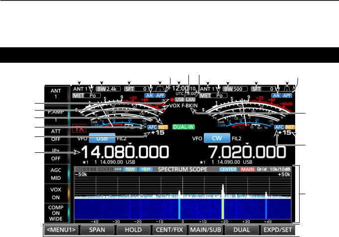
qMULTI-FUNCTION KEY GROUP
Displays the Multi-function keys. |
|
wANTENNA INDICATOR (p. 7-1) |
|
Displays the selected antenna connector between |
|
ANT 1 and ANT 2. |
|
eMETER TYPE INDICATOR (p. 3-7) |
|
Displays the selected transmit parameter type. |
|
Select between Po, SWR, ALC, COMP, Vd and Id. |
|
rBANDWIDTH INDICATOR (p. 4-3, 4-4) |
|
Displays the passband width of the IF filter. |
|
tSHIFT FREQUENCY INDICATOR (p. 4-3) |
|
Displays the shift frequency of the IF filter. |
|
yNOTCH INDICATOR (p. 4-6) |
|
“AN” is displayed when the Auto Notch function is |
|
ON, and “MN” is displayed when the Manual Notch |
|
function is ON. |
|
uPASSBAND WIDTH INDICATOR (p. 4-3) |
|
Displays the passband width for twin PBT operation |
|
and the center frequency for IF shift operation. |
|
iAUDIO PEAK FILTER (APF) INDICATOR (p. 4-12) |
|
Displayed when the Audio Peak Filter is ON. |
|
oCLOCK READOUT (p. 9-1) |
|
Displays the time (2 types) set on the TIME SET |
|
screen. |
|
!0USB INDICATOR (p. 6-1) |
|
Displayed while a USB flashed drive is inserted. |
|
!1LAN INDICATOR |
|
Displayed while the transceiver and the optional |
|
RS-BA1 are connected through the LAN for remote |
|
control operation. |
1-4 |
|
 !3
!3
 !4
!4
!5
 !6
!6
!7
 !8
!8
!2BK-IN/F-BKIN INDICATOR (p. 4-11)
Displayed while the Semi Break-in or Full Break-in function is ON.
!3NET FUNCTION INDICATOR (p. 8-7)
Displayed when the NET function is ON while in the PSK mode.
!4FREQUENCY OFFSET READOUT
Displays the offset value between the PSK signal and the operating frequency, while a PSK signal is received.
!5AFC FUNCTION INDICATOR
Displayed while the Automatic Frequency Control (AFC) function is ON, in the PSK mode.
!6FREQUENCY READOUT (p. 3-4)
Displays the operating frequency.
LThe non-selected band’s frequency readout (Main or Sub) is displayed in gray.
!7FUNCTION DISPLAY
Displayed when an item that has a function display is selected. For example, the Spectrum Scope.
!8FUNCTION KEYS (p. 5-1)
Displays the operating parameters, modes, frequencies and indicators, and so on.
!9VOX INDICATOR
Displayed while the VOX function is ON.
@0VOICE RECORDER ICON
••“●” is displayed while recording. ••“ ” is displayed while pausing.
1 PANEL DESCRIPTION
Touch screen display (Continued)
@5@6 @7@8@9#0#1#2#3#4@1@4@3@2@6@7@8 @9@5
@4
@3
@2
@1
#9#8 #7 |
#6#5$1$0#9 #8 #7 |
#6#5 |
@1VFO/MEMORY ICON (p. 3-1)
“VFO” is displayed when the VFO mode is selected, and the memory number is displayed when a Memory channel is selected.
@2TX STATUS INDICATOR (p. 3-4, 3-9)
Displays the transmit status of the displayed frequency.
•• is displayed while the displayed frequency is within
the amateur band range.
••
 (Red background) is displayed while transmitting. ••
 (With a border of short dashes) is displayed when the selected frequency is outside of the amateur band
frequency.
•• (Grayed out) is displayed while the transmitter is inhibited.
@3RF GAIN INDICATOR (p. 3-7)
Displayed when AF
 RF/SQL (outer) is set counterclockwise from the 11 o’clock position. The indicator shows that the RF gain is reduced.
@4OVF ICON (p. 3-7)
“OVF” is displayed when an excessively strong signal is received.
@5METER INDICATOR (p. 3-7)
Displays the S, Id, Po, SWR, COMP, ALC and Vd meters.
@6MODE INDICATOR (p. 3-3)
Displays the selected operating mode.
@7IF FILTER INDICATOR (p. 4-3, 4-4)
Displays the selected IF filter.
@8QUICK TUNING ICON (p. 3-4)
Displayed when the quick Tuning Step function is ON.
@9AUTO TUNE INDICATOR (p. 4-8)
Displays “AUTOTUNE” when the Auto Tuning function is ON.
#0SPLIT ICON (p. 4-9)
Displayed when the Split function is ON.
#1DUALWATCH ICON (p. 3-2)
Displayed when using Dualwatch.
#2SHIFT FREQUENCY READOUT (p. 4-1)
Displays the shift offset for the RIT or  TX functions, while these functions are ON.
#3RIT ICON (p. 4-1)
Displayed when the RIT function is ON.
#4TX ICON
Displayed when the  TX function is ON.
#51/4 TUNING STEP INDICATOR (p. 3-5)
Displayed while the 1/4 Tuning Step function is ON.
#6M1~M8/T1~T8
••Displays “M1”~“M8” while using the Memory Keyer function is used.
••Displays “T1”~“T8” while using the Voice TX memory function.
#7MEMORY CHANNEL/VFO READOUT (p. 3-1)
Displays the selected memory channel contents in the VFO mode, and displays the VFO contents in the Memory mode.
#8LMT ICON
Displayed if the power amplifier temperature becomes extremely high and the protection function is activated after transmitting continuously for long periods of time.
#9SELECT MEMORY CHANNEL ICON
Indicates that the displayed memory channel is assigned as a Select memory channel ( 1~ 3).
$0PLAY ICON
Displayed while playing the recorded voice audio.
$1DIAL LOCK INDICATOR (p. 3-6)
Displayed while the Lock function is ON.
1-5
Touch screen display (Continued)
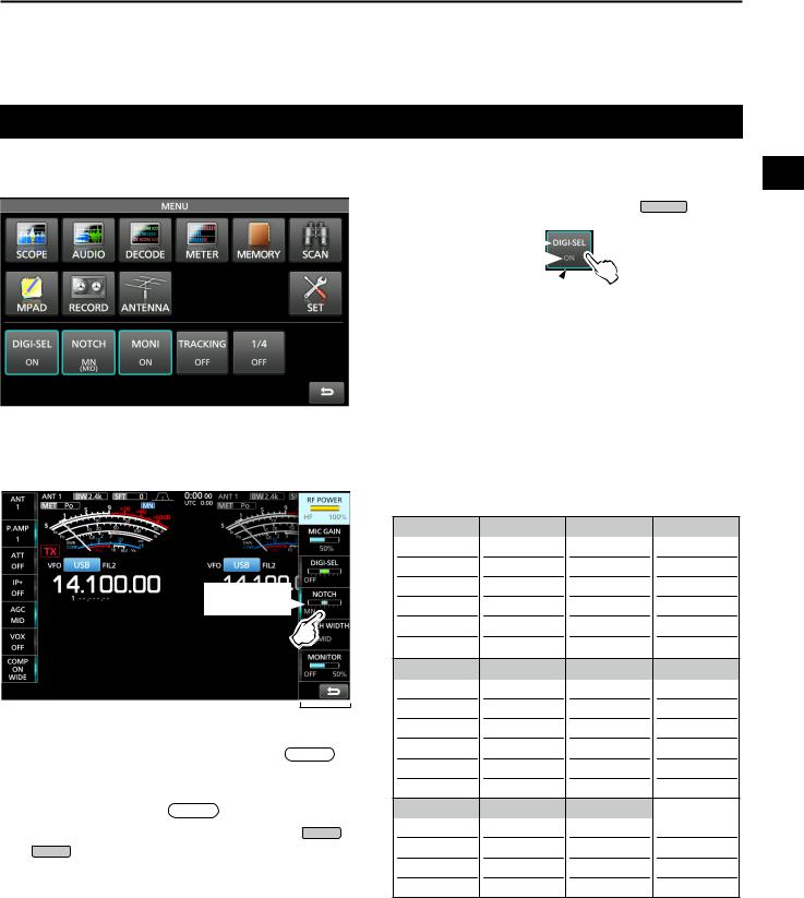
DDMENU screen
PANEL DESCRIPTION |
1 |
1
zzOpen the MENU screen by pushing MENU .
Function name  Status
Lights blue or orange  when in use
LThe items displayed on the menu differ, depending on the selected operating mode.
DDMulti-function menus
Touch to turn
ON or OFF
Multi-function menu 
zzOpen the Multi-function menu by pushing  MULTI (Multi-function control).
zzWhile the Multi-function menu is open, touch the desired item and rotate  MULTI to adjust the value.
LYou can open other menus by holding down NB or NR for 1 second, or touching “ATT,” “VOX,” “BK-IN” or “COMP” in the Multi-function key group for 1 second.
Multi-function menu items
SSB |
CW |
RTTY |
PSK |
RF POWER |
RF POWER |
RF POWER |
RF POWER |
MIC GAIN |
|
|
|
DIGI-SEL |
DIGI-SEL |
DIGI-SEL |
DIGI-SEL |
NOTCH |
NOTCH |
NOTCH |
NOTCH |
NOTCH WIDTH NOTCH WIDTH NOTCH WIDTH NOTCH WIDTH |
|||
MONITOR |
|
MONITOR |
MONITOR |
AM |
FM |
NB |
NR |
RF POWER |
RF POWER |
LEVEL |
LEVEL |
MIC GAIN |
MIC GAIN |
DEPTH |
|
DIGI-SEL |
DIGI-SEL |
WIDTH |
|
NOTCH NOTCH
NOTCH WIDTH
MONITOR MONITOR
ATT |
VOX |
BK-IN |
COMP |
LEVEL |
GAIN |
DELAY |
LEVEL |
|
ANTI VOX |
|
TBW |
|
DELAY |
|
|
|
VOICE DELAY |
|
|
1-6
1 PANEL DESCRIPTION
Touch screen display (Continued)
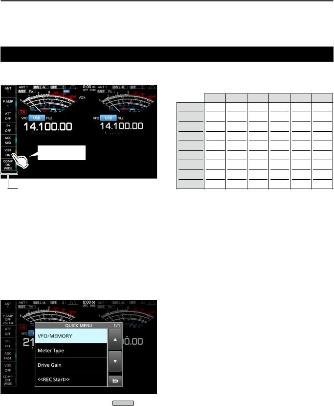
DDMulti-function key group
Touch to turn ON or OFF, or to set
Multi-function key group
zzTouch a key to turn the function ON or OFF.
zzTouching “ATT,” “VOX,” “BK-IN” or “COMP” for 1 second opens the ATT menu, VOX menu, BK-IN menu or COMP menu.
LSee “Multi-function menus” on the previous page for details.
DDQUICK MENU
zzOpen the QUICK MENU by pushing QUICK .
Multi-function key group items
|
SSB |
CW |
RTTY |
PSK |
AM |
FM |
ANT |
|
|
|
|
|
|
P.AMP |
|
|
|
|
|
|
ATT |
|
|
|
|
|
|
IP+ |
|
|
|
|
|
|
AGC |
|
|
|
|
|
|
VOX |
|
|
|
|
|
|
BK-IN |
|
|
|
|
|
|
COMP |
|
|
|
|
|
|
TONE |
|
|
|
|
|
|
1-7
PANEL DESCRIPTION |
1 |
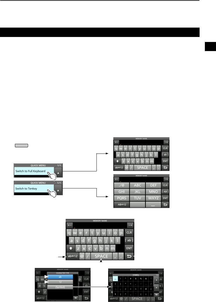
Keyboard entering and editing
You can enter and edit the items on the following screens. |
1 |
LUsable characters, symbols, and the amount of characters that can be entered differs, depending on the editing item. |
••MY CALL
••FILE NAME ••NETWORK NAME
••NETWORK RADIO NAME ••NETWORK USER1 ID ••NETWORK USER2 ID ••NETWORK USER 1 PASSWORD ••NETWORK USER 2 PASSWORD ••NTP SERVER ADDRESS ••CLOCK2 NAME
••KEYER MEMORY ••PSK MEMORY ••RTTY MEMORY
••VOICE TX RECORD (T1) ~ (T8) ••MEMORY NAME
DDKeyboard types
You can select the Full Keyboard or Tenkey by pushing QUICK while displaying an entry mode screen.
DDEntering and editing
Moves the cursor backward 
Enters an uppercase letter 
Selects alphabet mode or number mode
Alphabet mode 
Number mode 
Symbol mode 
 Moves the cursor forward
 Clears the entered character
 Selects the character type
 Saves the entry
 Cancels entry and returns to the previous screen
 Enters a space
1-8

1 PANEL DESCRIPTION
Keypad entering and editing (Continued)
DDEntering and editing example
Entering “DX spot 1” in the Memory channel 2
1.Display the MEMORY screen.
MENU » MEMORY
2.Touch the memory channel 2 for 1 second.
••The MEMORY MENU screen is displayed.
You can also display the MEMORY
MENU screen by touching this key.
3.Touch “Edit Name.”
••The MEMORY NAME screen is displayed.
7.Touch [s], [p], [o], and then [t].
8.Touch [SPACE] to enter a space.
9.Touch [ab].
••The CHARACTER TYPE screen is displayed.
10. Touch [12].
4.Touch [ ], and then touch [D].
LTouching [ ] changes between uppercase and lowercase letter.
11. Touch [1].
12. Touch [ENT] to save the entry.
5.Touch [ ] again, and then touch [X].
6.Touch [SPACE] to enter a space.
••Returns to the previous screen.
1-9
INSTALLATION AND CONNECTIONS 2
Using the desktop stands
The transceiver has legs for desktop use. zzPull-out the legs on both sides until they lock in
place.
NOTE: DO NOT hold the stand, dials and controls when you carry the transceiver. This may damage them.
Selecting a location
Select a location for the transceiver that allows adequate air circulation, free from extreme heat, cold or vibrations, and other electromagnetic sources.
Never place the transceiver in areas such as: ••Temperatures below 0°C (+32°F) or above +50°C
(+122°F).
••An unstable place that slopes or vibrates. ••In direct sunlight.
••High humidity and temperature environments. ••Dusty environments.
••Noisy environments.
Heat dissipation
••NEVER install the transceiver in a place without adequate ventilation. Heat dissipation may be reduced, and the transceiver may be damaged.
••DO NOT place the transceiver against walls or put 2 anything on top of the transceiver. This may block
airflow and overheat the transceiver.
••DO NOT touch the rear panel after transmitting continuously for long periods of time. The panel may become hot.
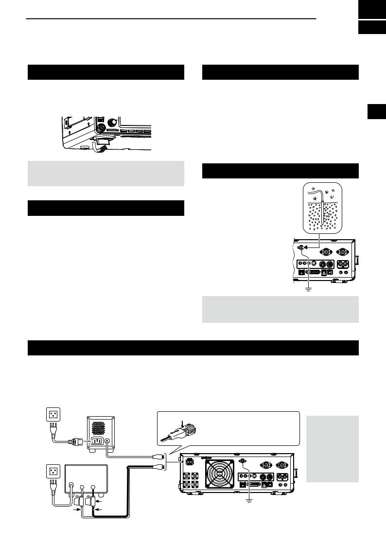
Grounding
To prevent electrical shock, television interference (TVI), broadcast interference (BCI) and other problems, ground the transceiver using the ground terminal [GND] on the rear panel.
For best results, connect a heavy gauge wire or strap to a long ground rod. Make the distance between the [GND] terminal and ground as short as possible.
RWARNING! NEVER connect the [GND] terminal to a gas or electric pipe, since the connection could cause an explosion or electric shock.
Connecting an external DC power supply
Be sure that the power supply power is OFF before connecting the DC power cable.
We recommend using Icom’s optional PS-126 (13.8 V DC/25 A) power supply.
LWhen using a non-Icom DC power supply, you need: ••13.8 V DC (Capacity: At least 23 A)
••A power supply with an over current protective line and low voltage fluctuation or ripple.
AC Outlet |
|
|
|
|
PS-126 |
q |
|
|
|
To disconnect, firmly push down |
|
|
w |
|
|
|
|
the locking tab and then pull the |
|
|
|
|
connector out of the socket. |
AC cable |
DC power cable |
|
|
|
|
|
|
Non-Icom DC power supply |
|
|
|
13.8 V DC/23 A |
|
|
|
or more |
|
|
|
+ |
_ |
|
|
|
Fuse |
|
GND |
Red |
Black |
|
|
|
|
||
2-1
CAUTION: DO NOT touch
the rear panel of the transceiver after transmitting continuously
for long periods of time. It can become very hot.
2 INSTALLATION AND CONNECTIONS
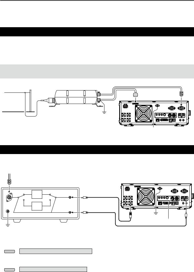
Connecting the antenna tuner
The AH-4 matches the IC-7610 to the optional AH-2b or to a long wire antenna more than 7 m/23 ft long (usable between 3.5 and 50 MHz).
LSee the AH-4 instruction manual for installation and connection details.
LSee the Advanced Manual for connecting the optional AH-740 automatic antenna tuner.
NOTE:
••Before connecting, be sure to turn OFF the transceiver.
••While the AH-4 is connected, the IC-7610ʼs internal antenna tuner is deactivated.
HF band long wire |
AH-4 |
|
antenna |
||
|
Coaxial cable (50 Ω)
[TUNER] |
[ANT 1] |
GND
 GND
GND
Connecting a Transverter
Connect your transverter unit as described below.
LYou may need to connect to [ALC], depending on the transverter.
VHF/UHF band antenna
Transverter
RX |
TRV |
RX |
RF IN/OUT |
Coaxial cable (50 Ω) |
|
|
ANT |
TX |
TRV |
TX |
|
|
[SEND] |
|
||
|
|
|
||
|
|
|
|
|
|
|
|
[X-VERTER] |
[SEND] |
|
|
|
GND |
|
|
|
|
|
GND
••Set the “Transverter Function” item to ON to use the transverter operating mode.
You can also use the transverter operating mode by connecting a DC voltage to [ACC 2 (6: TRV)].
MENU » SET > Function > Transverter Function
LYou cannot select the antenna or use the internal tuner while using the Transverter function. ••Set the offset frequency for the transverter operation.
MENU » SET > Function > Transverter Offset
2-2
INSTALLATION AND CONNECTIONS |
2 |
Linear amplifier connections
DDConnecting the IC-PW1/IC-PW1EURO
See the illustration below to connect the optional IC-PW1 or IC-PW1EURO hf/50 mhz all band 1 kw linear amplifier. |
|
||||
Refer to the amplifier’s instruction manual for operation. |
|
|
2 |
||
|
|
ACC cable |
|
|
|
To an |
|
|
|
|
|
antenna |
[ACC 1] |
Remote control cable |
|
|
|
|
|
|
|||
|
|
[REMOTE] |
|
|
|
|
|
[INPUT 1] |
Coaxial cable (50 Ω) |
[ACC 2] |
|
|
|
|
|
||
|
|
|
|
|
|
|
|
[REMOTE] |
EXCITER |
[ANT 1] |
|
|
||
1 |
1 |
& 2 |
GND
To an AC outlet
 Non-European versions: 100~120/200~240 V
European version: |
230 V |
R WARNING! When using a linear amplifier such as the IC-PW1 or IC-PW1EURO, set the RF POWER in the Multi-function menu to keep the ALC meter in the red zone.
LSee page 3-8 for details on the RF POWER settings. LSee page 3-9 for details on the ALC zone settings.
DDConnecting a non-Icom linear amplifier
See the illustration below to connect a non-Icom linear amplifier.
LWe recommend that you use a linear amplifier with a specified input power of 100 watts or more. If you use an amplifier with a specified drive level of less than 100 watts, adjust the IC-7610’s output power to the specified level before transmitting. Otherwise the linear amplifier may be damaged.
To an antenna |
|
|
[ANT1] |
|
Coaxial cable (50 Ω) |
|
|
Non-Icom |
|
or |
|
linear amplifier |
|
|
[ANT2] |
RF OUT RF IN |
|
|
|
|
ALC |
|
|
|
SEND |
|
|
|
GND |
|
|
|
GND |
[ALC] |
[SEND] |
|
GND |
||
|
|
|
R WARNING!
••The maximum signal level of the [SEND] jack is 16 V/0.5 A DC, and 250 V/200 mA with the “MOSFET” setting (p. 13-2). Use an external unit if your non-Icom linear amplifier requires a control voltage and/or current greater than specified.
••The ALC input level must be in the range 0 to –4 V. The transceiver does not accept a positive voltage. Non-matched ALC and RF power settings could overheat or damage the linear amplifier.
2-3
3 BASIC OPERATION
When first applying power
Before turning ON your transceiver for the first time, make sure all connections are correctly made.
After all connections are made, set the dials to the positions described below.
q |
|
w |
t |
|
|
e |
y |
r |
|
qMAIN
wMAIN
eSUB
rSUB
AF
 RF/SQL (inner): Fully counterclockwise AF
 RF/SQL (outer): 12 o’clock
AF
 RF/SQL (inner): Fully counterclockwise AF
 RF/SQL (outer): 12 o’clock
t KEYSPEED
 PITCH (inner): Fully counterclockwise y KEYSPEED
 PITCH (outer): 12 o’clock
TIP: When you turn OFF the transceiver, it saves the current settings. Therefore, when you turn ON the transceiver again, it starts with the same settings.
Turning power ON or OFF |
|
|
Adjusting the volume level |
||
zzTo turn ON the transceiver, push POWER . |
|
Rotate AF |
|
RF/SQL (inner) to adjust the volume level. |
|
|
|
||||
zzTo turn OFF the transceiver, hold down POWER |
for |
||||
2 seconds until “POWER OFF...” is displayed. |
|
|
|
|
|
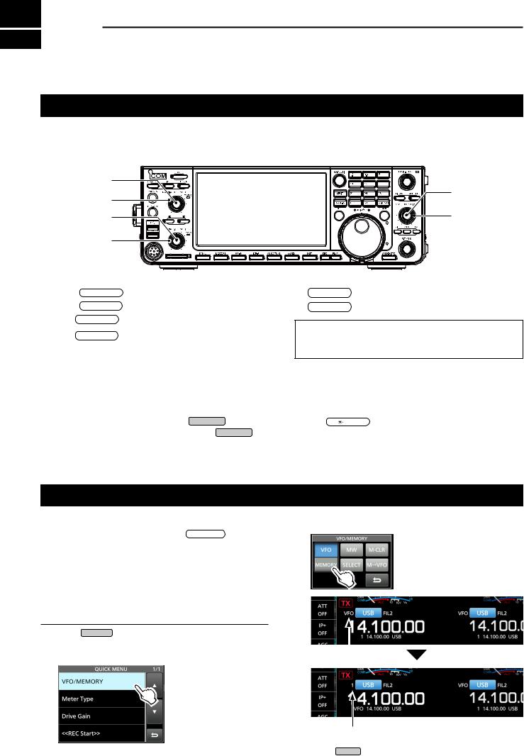
Selecting the VFO and Memory modes
VFO mode
You can set a frequency by rotating MAIN DIAL .
LUsing the VFO mode may be easier for the first initial operation.
Memory mode
You can recall a frequency that you have memorized on the MEMORY list.
Selecting the VFO mode or Memory mode
1.Push QUICK .
••The QUICK MENU screen is displayed.
2.Touch “VFO/MEMORY.”
3. Touch [VFO] or [Memory] to select the mode.
|
|
|
VFO mode screen |
|
|
|
|
VFO indicator |
|
||
|
|
||
Memory mode screen
Memory channel number
4. Push EXIT to close the VFO/MEMORY screen.
3-1
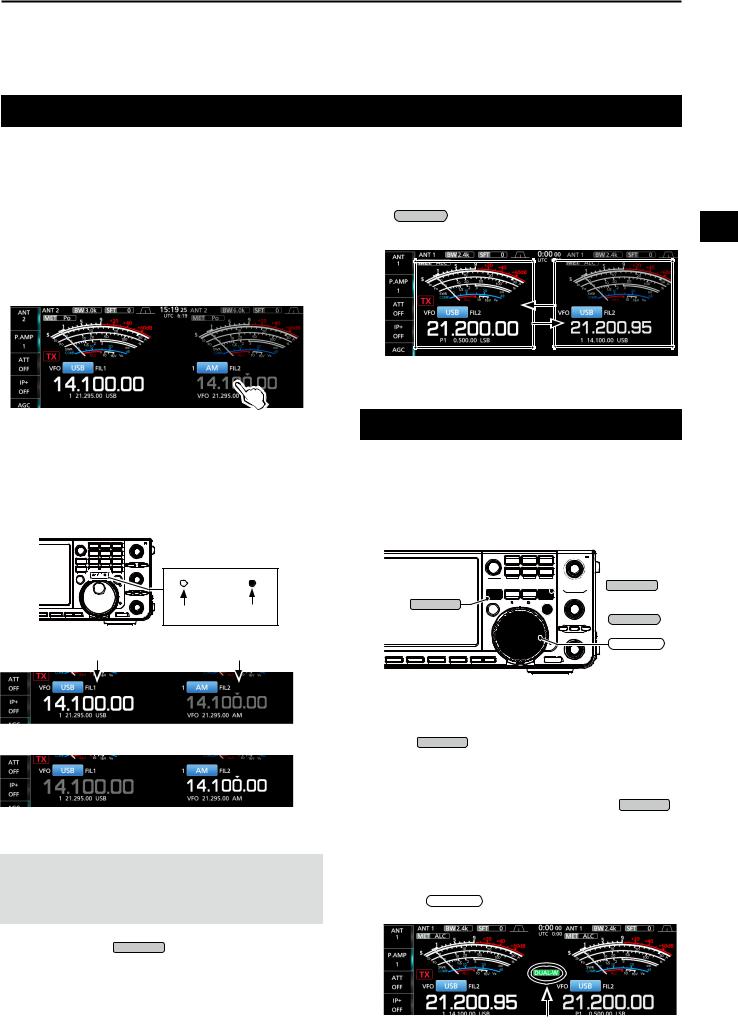
Selecting the Main and Sub bands
The IC-7610 has 2 identical receivers, Main and Sub. The Main band is displayed on the left side of the screen, and the Sub band is displayed on the right side. Some functions can only be applied to the selected band, and you can transmit on only the Main band (except in Split Frequency operation).
To select the Main band or Sub band, touch the frequency readout.
••The selected band’s frequency readout is displayed clearly, and the frequency of the non-selected band is grayed.
••The selected band’s indicator lights as described below.
Example: When the Sub band is selected, the MAIN/SUB indicator lights on the Sub band side.
MAIN/SUB |
|
Not lit |
Lit |
Main |
Sub |
BASIC OPERATION |
3 |
DDSwitching the Main band and Sub band
You can switch the Main band and Sub band settings, such as the operating frequency, mode, and so on.
Push CHANGE . |
3 |
••The Main and Sub band settings are switched. |
Dualwatch operation
Dualwatch simultaneously monitors two frequencies. The IC-7610 has 2 independent receiver circuits, the Main and Sub bands, so that you can use Dualwatch with no compromises, even on different bands and modes.


 MAIN/SUB
DUAL-W


 CHANGE
MAIN DIAL
The Main band is selected.
The Sub band is selected.
NOTE: The Sub band readout is activated during Split operation or Dualwatch operation.
••See page 4-9 for details on Split operation.
••See the right column for details on Dualwatch operation.
LYou can also push MAIN/SUB to select the Main band or Sub band.
DDUsing the Dualwatch operation
1.Push DUAL-W briefly to start the Dualwatch operation.
••“DUAL-W” is displayed.
LTo equalize the Sub band frequency and mode to those of the Main band, hold down DUAL-W for 1 second. This Quick Dualwatch function can be turned OFF in the Others set screen.
(p. 8-3)
2.Touch the frequency readout of the band you want to set the frequency.
3.Rotate MAIN DIAL to set the frequency.
Displayed
3-2
3 BASIC OPERATION
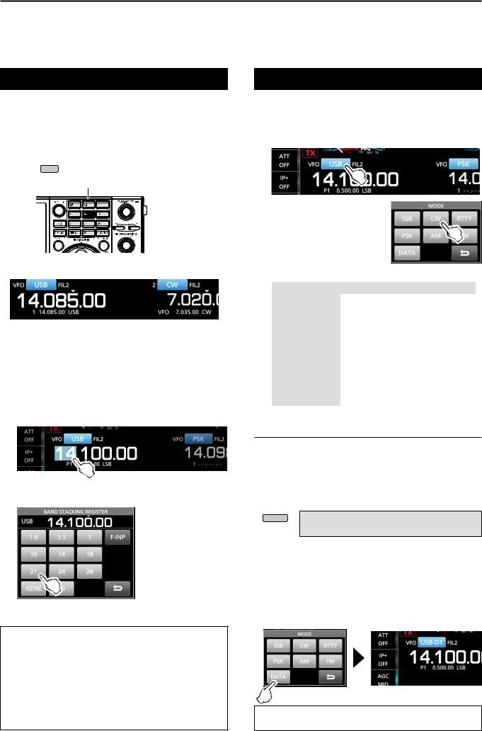
Selecting the operating band
DDSelecting the operating band on the
keypad
(Example: Selecting 14 MHz in the Main band.)
1.Touch the Main band’s frequency readout.
2.Push 14 on the band keypad.
Keypad
••The 14 MHz band frequency is displayed.
DDSelecting the operating band on the
screen
(Example: Selecting 21 MHz in the Main band.)
1.Touch the MHz digits to display the BAND STACKING REGISTER screen.
2.Touch [21].
About the Band Stacking Register:
The band stacking register provides 3 memories for each band key to store frequencies and operating modes.
Sequentially select the registered memories: zzRepeatedly push a band key on the keypad. zzRepeatedly touching a band key on the BAND STACKING REGISTER screen for 1 second.
Selecting the operating mode
You can select the SSB, CW, RTTY, PSK, AM, or FM modes.
1.Touch the mode icon.
2.Touch the mode key.
LIn the SSB, AM or FM mode, the [DATA] key is displayed.
••Operating mode selection list |
|
|
||
|
Mode key |
Operating mode |
||
|
[SSB] |
LSB |
|
USB |
|
[CW] |
CW |
|
CW-R |
|
[RTTY] |
RTTY |
|
RTTY-R |
|
[PSK] |
PSK |
|
PSK-R |
|
[AM] |
|
AM |
|
|
[FM] |
|
FM |
|
|
|
LSB |
|
LSB-D |
|
[DATA] |
USB |
|
USB-D |
|
AM |
|
AM-D |
|
|
|
|
||
|
|
FM |
|
FM-D |
Selecting the Data mode
You can operate in the Data mode in the SSB, AM and FM modes. The Data mode enables you to operate in these modes with input from various connectors, even if the microphone is connected.
LWhen the data mode is selected, you can select the connector that will input the modulation signal. (p. 8-6)
MENU » SET > Connectors >
DATA OFF MOD, DATA1 MOD ~ DATA3 MOD
zzSelect the connector(s) to input the modulation signal. (Example: USB-D mode)
1.While the USB mode is selected, touch the mode icon.
2.Touch [DATA].
••[USB-D1] is displayed.
••The selected connector will be used to input the modulation signal.
TIP: See page 36 in the Advanced Manual for details on using the AFSK Data mode.
3-3
Loading...