


 Loading...
THE TRANSCEIVER
i7800
Instruction Manual
A-6328H-1EX-!6
Printed in Japan
© 2004–2015 Icom Inc.

FOREWORD
Congratulations! You are the owner of the world’s most advanced amateur HF/50 MHz transceiver— IC-7800. The IC-7800 is designed and built with Icom’s superior technology and craftsmanship. With proper care, this product should provide you with years of trouble-free operation.
We would like to take a few moments of your time to thank you for making the IC-7800 your radio of choice, and hope you agree with Icom’s philosophy of “technology first.” Many hours of research and development went into the design of your IC-7800.
D FEATURES
Ultimate receiver performance: third-order intercept (IP3) of +40 dBm (HF bands only), both main and sub
Independent identical receiver circuits for main and sub bands provide perfect no-compromise Dualwatch operation
Built-in Baudot RTTY and PSK31 modulator/demodulator and direct PC keyboard connection capability for RTTY and PSK31 operation without a PC
Upgraded real-time spectrum scope— center frequency and fix frequency modes, plus mini-scope displays
IMPORTANT
READ THIS INSTRUCTION MANUAL CAREFULLY before attempting to operate the transceiver.
SAVE THIS INSTRUCTION MANUAL. This manual contains important safety and operating instructions for the IC-7800.
EXPLICIT DEFINITIONS
WORD |
DEFINITION |
R DANGER! Personal death, serious injury or an explosion may occur.
R WARNING! Personal injury, fire hazard or electric shock may occur.
CAUTION Equipment damage may occur.
NOTE |
Recommended for optimum use. No risk of personal |
|
injury, fire or electric shock. |
||
|
TRADEMARKS
Icom, Icom Inc. and the Icom logo are registered trademarks of Icom Incorporated (Japan) in Japan, the United States, the United Kingdom, Germany, France, Spain, Russia, Australia, New Zealand, and/or other countries.
i

PRECAUTIONS
R DANGER HIGH RF VOLTAGE! NEVER attach an antenna or internal antenna connector during transmission. This may result in an electrical shock or burn.
R WARNING! NEVER operate the transceiver with a headset or other audio accessories at high volume levels. Hearing experts advise against continuous high volume operation. If you experience a ringing in your ears, reduce the volume or discontinue use.
R WARNING! NEVER operate or touch the transceiver with wet hands. This may result in an electric shock or damage to the transceiver.
R WARNING! NEVER let metal, wire or other objects protrude into the transceiver or into connectors on the rear panel. This may result in an electric shock.
R WARNING! Immediately turn the transceiver power OFF and remove the power cable if it emits an abnormal odor, sound or smoke. Contact your Icom dealer or distributor for advice.
CAUTION: NEVER put the transceiver in any unstable place (such as on a slanted surface or vibrated place). This may cause injury and/or damage to the transceiver.
CAUTION: NEVER change the internal settings of the transceiver. This may reduce transceiver performance and/or damage to the transceiver.
In particular, incorrect settings for transmitter circuits, such as output power, idling current, etc., might damage the expensive final devices.
The transceiver warranty does not cover any problems caused by unauthorized internal adjustment.
CAUTION: NEVER block any cooling vents on the top, rear or bottom of the transceiver.
CAUTION: NEVER expose the transceiver to rain, snow or any liquids.
CAUTION: NEVER install the transceiver in a place without adequate ventilation. Heat dissipation may be reduced, and the transceiver may be damaged.
CAUTION: The line-voltage receptacle must be near the transceiver and must be easily accessible. Avoid extension cords.
CAUTION: The transceiver weighs approximately 25 kg (55 lb). Always have two people available to carry, lift or turn over the transceiver.
DO NOT use harsh solvents such as benzine or alcohol when cleaning, as they can damage the transceiver’s surfaces.
DO NOT push the PTT switch when you don’t actually desire to transmit.
DO NOT use or place the transceiver in areas with temperatures below ±0°C (+32°F) or above +50°C (+122°F).
DO NOT place the transceiver in excessively dusty environments or in direct sunlight.
DO NOT place the transceiver against walls or putting anything on top of the transceiver. This may overheat the transceiver.
Always place unit in a secure place to avoid inadvertent use by children.
BE CAREFUL! If you use a linear amplifier, set the transceiver’s RF output power to less than the linear amplifier’s maximum input level, otherwise, the linear amplifier will be damaged.
BE CAREFUL! NEVER touch the transceiver top cover when transmitting continuously for long periods. The top cover may be hot.
Use Icom microphones only (supplied or optional). Other manufacturers’ microphones have different pin assignments, and connection to the IC-7800 may damage the transceiver or microphone.
The LCD display may have cosmetic imperfections that appear as small dark or light spots. This is not a malfunction or defect, but a normal characteristic of LCD displays.
During maritime mobile operation, keep the transceiver and microphone as far away as possible from the magnetic navigation compass to prevent erroneous indications.
Turn [I/O] switch (on the rear panel) OFF and/or disconnect the AC power cable from the AC outlet when you will not use the transceiver for long period of time.
ii
SUPPLIED ACCESSORIES
q |
w |
e |
r |
t |
y |
u |
|
|
|
|
|
i |
|
|
|
o |
!0 |
||||||||||
|
|
|
|
|
|
|
|
|
|
|
|
|
|
|
|
|
|
|
|
|
|
|
|
|
|
|
|
|
|
|
|
|
|
|
|
|
|
|
|
|
|
|
|
|
|
|
|
|
|
|
|
|
|
|
|
|
|
|
|
|
|
|
|
|
|
|
|
|
|
|
|
|
|
|
|
|
|
|
|
|
|
|
|
|
|
|
|
|
|
|
|
|
|
|
|
!1 |
!2 |
!3 |
!4 |
!5 |
!6 |
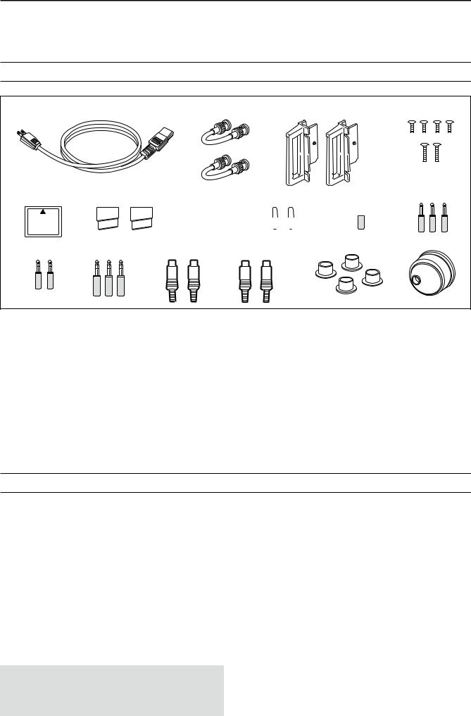
q AC power cable*1 1 w Antenna jumper cables 2 e Rack mounting handles 1 pair r Screws for rack mounting handles 1 set t CF (Compact Flash) memory card 1 y Stands 1 pair u Spare fuse (FGB 2 A) 1 i RCA plugs 2 o DC power plug 1
!02-conductor 1⁄8″ plugs 3 !13-conductor 1⁄8″ plugs 2 !23-conductor 1⁄4″ plugs 3 !3ACC plugs (7-pin) 2 !4ACC plugs (8-pin) 2 !5Antenna connector caps 4 !6Main dial*2 1
*1May differ from that shown depending on the version *2See the “Information—About the Main Dial” leaflet that
comes with the IC-7800, for dial attachment details.
FCC INFORMATION
FOR CLASS B UNINTENTIONAL RADIATORS
This equipment has been tested and found to comply with the limits for a Class B digital device, pursuant to part 15 of the FCC Rules. These limits are designed to provide reasonable protection against harmful interference in a residential installation. This equipment generates, uses and can radiate radio frequency energy and, if not installed and used in accordance with the instructions, may cause harmful interference to radio communications. However, there is no guarantee that interference will not occur in a particular installation. If this equipment does cause harmful interference to radio or television reception, which can be determined by turning the equipment off and on, the user is encouraged to try to correct the interference by one or more of the following measures:
•Reorient or relocate the receiving antenna.
•Increase the separation between the equipment and receiver.
•Connect the equipment into an outlet on a circuit different from that to which the receiver is connected.
•Consult the dealer or an experienced radio/TV technician for help.
CAUTION: Changes or modifications to this device, not expressly approved by Icom Inc., could void your authority to operate this device under FCC regulations.
iii

TABLE OF CONTENTS
Section 1 PANEL DESCRIPTION
■ Front panel………………………………………………………………… 1-2 ■ Rear panel… ……………………………………………………………… 1-12 ■ Accessory connector information… …………………………………… 1-14 ■ LCD display………………………………………………………………… 1-15 ■ Screen menu arrangement… …………………………………………… 1-16
Section 2 INSTALLATION AND CONNECTIONS
■Unpacking… ……………………………………………………………… 2-2
■Antenna jumper cable connection… …………………………………… 2-2
■Selecting a location… …………………………………………………… 2-2
■Rack mounting handle attachment……………………………………… 2-2
■Grounding… ……………………………………………………………… 2-3
■Antenna connection… …………………………………………………… 2-3
■CF (Compact Flash) memory card……………………………………… 2-3
■Required connections… ………………………………………………… 2-4 D Front panel……………………………………………………………… 2-4 D Rear panel… …………………………………………………………… 2-4
■Advanced connections…………………………………………………… 2-5 D Front panel……………………………………………………………… 2-5 D Rear panel—1… ……………………………………………………… 2-5 D Rear panel—2… ……………………………………………………… 2-6
■Linear amplifier connections… ………………………………………… 2-7 D Connecting the IC-PW1/EURO… …………………………………… 2-7 D Connecting a non-Icom linear amplifier……………………………… 2-7
■Transverter jack information……………………………………………… 2-8
■FSK and AFSK connections……………………………………………… 2-8 D When using the ACC socket or the microphone connector… …… 2-8
■Microphones (options)… ………………………………………………… 2-9 D SM-50…………………………………………………………………… 2-9 D SM-30…………………………………………………………………… 2-9 D HM-36…………………………………………………………………… 2-10
■Microphone connector information……………………………………… 2-10
Section 3 BASIC OPERATIONS
■When first applying power (CPU resetting)… ………………………… 3-2
■Initial settings……………………………………………………………… 3-2
■Main/Sub band selection… ……………………………………………… 3-3
■Selecting VFO/memory mode…………………………………………… 3-3
■Selecting an operating band… ………………………………………… 3-4 D Using the band stacking registers… ………………………………… 3-4
■Frequency setting… ……………………………………………………… 3-5 D Tuning with the main dial……………………………………………… 3-5 D Direct frequency entry with the keypad……………………………… 3-5 D Quick tuning step… …………………………………………………… 3-6 D Selecting “kHz” step…………………………………………………… 3-6 D 1⁄4 tuning step function………………………………………………… 3-6 D Selecting 1 Hz step… ………………………………………………… 3-7 D Auto tuning step function……………………………………………… 3-7
■Operating mode selection………………………………………………… 3-8
■Volume setting… ………………………………………………………… 3-9
■RF gain adjustment… …………………………………………………… 3-9
■Squelch level adjustment………………………………………………… 3-9
■Meter indication selection………………………………………………… 3-10 D Multi-function digital meter… ………………………………………… 3-10 D Meter type selection…………………………………………………… 3-11
iv

TABLE OF CONTENTS
■Basic transmit operation… ……………………………………………… 3-12 D Transmitting… ………………………………………………………… 3-12 D Microphone gain adjustment… ……………………………………… 3-12 D Drive gain adjustment… ……………………………………………… 3-13
■Band edge warning beep………………………………………………… 3-13 D Programming the user band edge… ………………………………… 3-14
Section 4 RECEIVE AND TRANSMIT
■Operating SSB… ………………………………………………………… 4-2 D Convenient functions for receive……………………………………… 4-2 D Convenient functions for transmit… ………………………………… 4-3 D About 5 MHz band operation (USA version only)………………… 4-3
■Operating CW……………………………………………………………… 4-4 D Convenient functions for receive……………………………………… 4-4 D Convenient functions for transmit… ………………………………… 4-5 D About CW reverse mode……………………………………………… 4-5 D About CW pitch control………………………………………………… 4-5 D CW side tone function… ……………………………………………… 4-5 D APF (Audio Peak Filter) operation…………………………………… 4-6 D About 137 kHz band operation
(Europe, UK, Italy, Spain, France versions only)…………………… 4-6
■Electronic keyer functions………………………………………………… 4-7 D Memory keyer screen… ……………………………………………… 4-8 D Editing a memory keyer… …………………………………………… 4-9 D Contest number set mode… ………………………………………… 4-10 D Keyer set mode………………………………………………………… 4-11
■Operating RTTY (FSK)…………………………………………………… 4-13 D Convenient functions for receive……………………………………… 4-14 D About RTTY reverse mode… ………………………………………… 4-14 D Twin peak filter… ……………………………………………………… 4-14 D Functions for the RTTY decoder indication… ……………………… 4-15 D Setting the decoder threshold level… ……………………………… 4-15 D RTTY memory transmission… ……………………………………… 4-16 D Automatic transmission/reception setting…………………………… 4-16 D Editing RTTY memory… ……………………………………………… 4-17 D RTTY decode set mode… …………………………………………… 4-18 D Data saving……………………………………………………………… 4-20
■Operating PSK… ………………………………………………………… 4-21 D Convenient functions for receive……………………………………… 4-22 D About BPSK and QPSK mode……………………………………… 4-22 D Functions for the PSK decoder indication…………………………… 4-23 D Setting the decoder threshold level… ……………………………… 4-23 D PSK memory transmission… ………………………………………… 4-24 D Automatic transmission/reception setting…………………………… 4-24 D Editing PSK memory…………………………………………………… 4-25 D PSK decode set mode………………………………………………… 4-26 D Data saving……………………………………………………………… 4-28
■Operating AM……………………………………………………………… 4-29 D Convenient functions for receive……………………………………… 4-29 D Convenient functions for transmit… ………………………………… 4-30
■Operating FM……………………………………………………………… 4-31 D Convenient functions for receive……………………………………… 4-31 D Convenient functions for transmit… ………………………………… 4-31
■Repeater operation… …………………………………………………… 4-32 D Repeater tone frequency setting……………………………………… 4-32
■Tone squelch operation… ……………………………………………… 4-33
■Data mode (AFSK) operation… ………………………………………… 4-34
v

TABLE OF CONTENTS
Section 5 FUNCTIONS FOR RECEIVE
■Spectrum scope screen… ……………………………………………… 5-2 D Center mode… ………………………………………………………… 5-2 D Fix mode………………………………………………………………… 5-3 D Mini scope screen indication… ……………………………………… 5-4 D Scope set mode………………………………………………………… 5-4 D USB mouse operation… ……………………………………………… 5-9
■Preamplifier………………………………………………………………… 5-10
■Attenuator… ……………………………………………………………… 5-10
■RIT function………………………………………………………………… 5-11 D RIT monitor function…………………………………………………… 5-11
■AGC function… …………………………………………………………… 5-12 D Selecting the preset value… ………………………………………… 5-12 D Adjusting the AGC time constant… ………………………………… 5-12 D Setting the AGC time constant preset value………………………… 5-12
■Twin PBT operation… …………………………………………………… 5-13
■IF filter selection…………………………………………………………… 5-14 D IF filter selection………………………………………………………… 5-14 D Filter passband width setting (except FM mode)…………………… 5-14 D Roofing filter selection… ……………………………………………… 5-15 D DSP filter shape………………………………………………………… 5-15 D Filter shape set mode… ……………………………………………… 5-15
■Dualwatch operation……………………………………………………… 5-17
■Noise blanker……………………………………………………………… 5-18 D NB set mode… ………………………………………………………… 5-18
■Noise reduction… ………………………………………………………… 5-19
■Dial lock function… ……………………………………………………… 5-19
■Notch function……………………………………………………………… 5-20
■Digital selector… ………………………………………………………… 5-20
■Audio scope screen… …………………………………………………… 5-21 D Audio scope set mode… ……………………………………………… 5-22
Section 6 FUNCTIONS FOR TRANSMIT
■VOX function… …………………………………………………………… 6-2 D Using the VOX function… …………………………………………… 6-2
D Adjusting the VOX function…………………………………………… 6-2
D VOX set mode… ……………………………………………………… 6-2
■Break-in function… ……………………………………………………… 6-3 D Semi break-in operation… …………………………………………… 6-3 D Full break-in operation………………………………………………… 6-3
■∂TX function… …………………………………………………………… 6-4 D ∂TX monitor function… ……………………………………………… 6-4
■Monitor function…………………………………………………………… 6-4
■Transmit filter width setting (SSB only)… ……………………………… 6-5
■Speech compressor (SSB only)… ……………………………………… 6-5
■Split frequency operation………………………………………………… 6-6
■Quick split function………………………………………………………… 6-7 D Split lock function… …………………………………………………… 6-7
vi

TABLE OF CONTENTS
Section 7 VOICE RECORDER FUNCTIONS
■Recording a QSO audio… ……………………………………………… 7-2 D To start or stop recording……………………………………………… 7-2
■Recording quick operation… …………………………………………… 7-2 D To start or stop recording……………………………………………… 7-2
■Playing back recorded audio (QSO)… ………………………………… 7-3 D Basic playing… ………………………………………………………… 7-3 D Operating while playing back… ……………………………………… 7-4
■Deleting recorded audio file……………………………………………… 7-5
■Deleting recorded audio folder…………………………………………… 7-5
■About digital voice recorder……………………………………………… 7-6
■Recording a received audio (Short REC)… …………………………… 7-7 D One-touch recording…………………………………………………… 7-7
■ Playing back the recorded audio (Short REC)… ……………………… 7-7 D Basic playing… ………………………………………………………… 7-7 D One-touch playing……………………………………………………… 7-8
■Protect the recorded contents…………………………………………… 7-8
■Erasing the recorded contents…………………………………………… 7-8
■Recording a message for transmit… …………………………………… 7-9 D Recording… …………………………………………………………… 7-9 D Confirming a message for transmit…………………………………… 7-9
■Programming a memory name… ……………………………………… 7-10
■Sending a recorded message…………………………………………… 7-11 D Single TX……………………………………………………………… 7-11 D Repeat TX… …………………………………………………………… 7-11 D Transmit level setting… ……………………………………………… 7-12
■Voice set mode… ………………………………………………………… 7-12
■Saving a voice memory into the memory device… …………………… 7-15 D Saving the received audio memory… ……………………………… 7-15 D Saving the TX memory………………………………………………… 7-15
Section 8 MEMORY OPERATION
■Memory channels… ……………………………………………………… 8-2
■Memory channel selection… …………………………………………… 8-2 D Using the [Y]/[Z] keys………………………………………………… 8-2 D Using the keypad… …………………………………………………… 8-2
■Memory list screen………………………………………………………… 8-3 D Selecting a memory channel using the memory list screen… …… 8-3 D Confirming programmed memory channels………………………… 8-3
■Memory channel programming… ……………………………………… 8-4
D Programming in VFO mode…………………………………………… 8-4
D Programming in memory mode… …………………………………… 8-4
■Frequency transferring…………………………………………………… 8-5
D Transferring in VFO mode… ………………………………………… 8-5
D Transferring in memory mode………………………………………… 8-5
■Memory names… ………………………………………………………… 8-6 D Editing (programming) memory names……………………………… 8-6
■Memory clearing…………………………………………………………… 8-6
■Memo pads………………………………………………………………… 8-7 D Writing frequencies and operating modes into memo pads… …… 8-7 D Calling up a frequency and operating mode from a memo pad…… 8-7
Section 9 SCANS
■Scan types… ……………………………………………………………… 9-2
■Preparation………………………………………………………………… 9-2
■Voice squelch control function…………………………………………… 9-3
■Scan set mode… ………………………………………………………… 9-3
■Programmed scan operation… ………………………………………… 9-4
vii

TABLE OF CONTENTS
■∂F scan operation………………………………………………………… 9-4
■Fine programmed scan/∂F scan………………………………………… 9-5
■Memory scan operation… ……………………………………………… 9-6
■Select memory scan operation… ……………………………………… 9-6
■Setting select memory channels………………………………………… 9-7 D Setting in scan screen… ……………………………………………… 9-7 D Setting in memory list screen… ……………………………………… 9-7 D Erasing the select scan setting… …………………………………… 9-7
■Tone scan… ……………………………………………………………… 9-8
Section 10 ANTENNA TUNER OPERATION
■Antenna connection and selection… …………………………………… 10-2
■Antenna memory settings………………………………………………… 10-3 D Antenna type selection………………………………………………… 10-3 D Temporary memory… ………………………………………………… 10-4 D Antenna selection mode… …………………………………………… 10-4
■Antenna tuner operation… ……………………………………………… 10-5 D Tuner operation………………………………………………………… 10-5 D If the tuner cannot tune the antenna… ……………………………… 10-6
Section 11 CLOCK AND TIMERS
■Time set mode… ………………………………………………………… 11-2
■Daily timer setting… ……………………………………………………… 11-3
■Setting sleep timer………………………………………………………… 11-4
■Timer operation… ………………………………………………………… 11-4
Section 12 SET MODE
■Set mode description……………………………………………………… 12-2 D Set mode operation… ………………………………………………… 12-2 D Screen arrangement…………………………………………………… 12-3
■Level set mode… ………………………………………………………… 12-4
■ACC set mode… ………………………………………………………… 12-6
■Display set mode… …………………………………………………… 12-11
■Others set mode………………………………………………………… 12-14
■CF/USB-MEMORY set menu… ……………………………………… 12-27 D CF/USB-MEMORY set screen arrangement…………………… 12-27 D Save option set mode… …………………………………………… 12-28 D Load option set mode… …………………………………………… 12-29
■File saving… …………………………………………………………… 12-30
■File loading……………………………………………………………… 12-31
■Changing the file name………………………………………………… 12-32
■Deleting a file…………………………………………………………… 12-33
■Formatting the memory device… …………………………………… 12-33
■Unmounting the memory device……………………………………… 12-34
Section 13 MAINTENANCE
■Troubleshooting…………………………………………………………… 13-2 D Transceiver power……………………………………………………… 13-2 D Transmit and receive………………………………………………… 13-2 D Scanning………………………………………………………………… 13-3 D Display…………………………………………………………………… 13-3
■Main dial brake adjustment… …………………………………………… 13-3
■Voice synthesizer operation……………………………………………… 13-3
■SWR reading… …………………………………………………………… 13-4
■Screen type and font selections… ……………………………………… 13-4
■Frequency calibration (approximate)… ………………………………… 13-5
■Opening the transceiver’s case… ……………………………………… 13-6
■Clock backup battery replacement……………………………………… 13-6
viii

TABLE OF CONTENTS
■Fuse replacement… ……………………………………………………… 13-7
■Resetting the CPU………………………………………………………… 13-7
■About protection indications……………………………………………… 13-8
■Screen saver function… ………………………………………………… 13-8
Section 14 CONTROL COMMAND
■Remote jack (CI-V) information… ……………………………………… 14-2
D CI-V connection example……………………………………………… 14-2 D Data format……………………………………………………………… 14-2 D Command table………………………………………………………… 14-3 D Data contents description…………………………………………… 14-10
Section 15 SPECIFICATIONS AND OPTIONS
■Specifications……………………………………………………………… 15-2 D General… ……………………………………………………………… 15-2 D Transmitter……………………………………………………………… 15-2 D Receiver………………………………………………………………… 15-3 D Antenna tuner…………………………………………………………… 15-3
■Options… ………………………………………………………………… 15-4
Section 16 UPDATING THE FIRMWARE
■General… ………………………………………………………………… 16-2
■Caution… ………………………………………………………………… 16-2
■Preparation………………………………………………………………… 16-3 D Firmware and firm utility… …………………………………………… 16-3 D File downloading… …………………………………………………… 16-3
■Firmware update— Memory device… ………………………………… 16-4
■Firmware update— PC…………………………………………………… 16-6 D Connections… ………………………………………………………… 16-6 D IP address setting……………………………………………………… 16-7 D Updating from the PC… ……………………………………………… 16-8
ix
PANEL DESCRIPTION |
Section 1 |
■Front panel………………………………………………………………… 1-2
■Rear panel… ……………………………………………………………… 1-12
■Accessory connector information… …………………………………… 1-14
■LCD display………………………………………………………………… 1-15
■Screen menu arrangement… …………………………………………… 1-16
1-1

1 PANEL DESCRIPTION
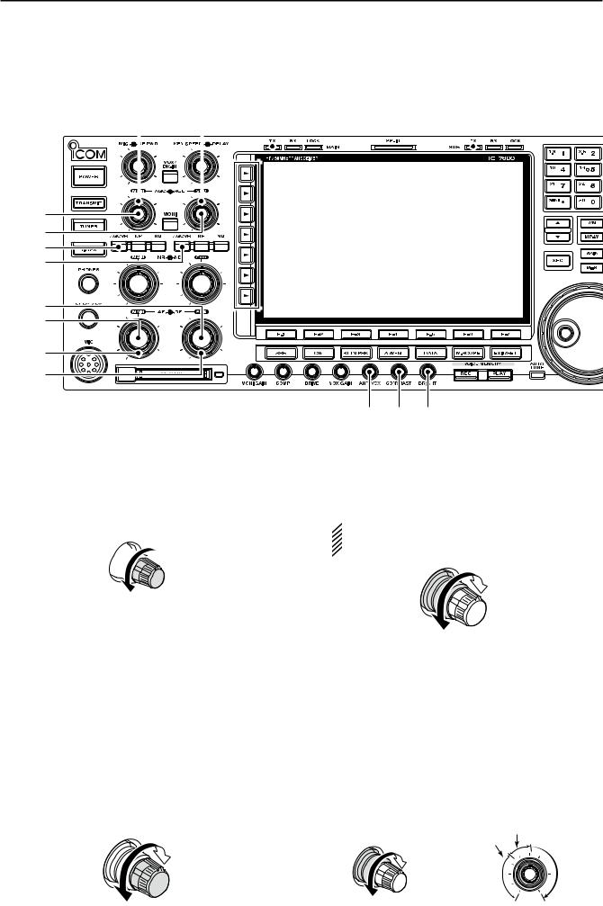
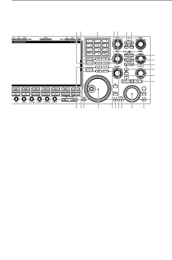
■Front panel
io !0 !1!2!3
q w e r
t
y
u
!4 !5 !6 !7 !8
q POWER SWITCH [POWER] (p. 3-2)
Turn the internal power supply ON in advance. The internal power supply switch is located on the rear panel. (p. 3-2)
Push to turn the transceiver power ON.
•The [POWER] indicator above this switch lights green when powered ON.
Hold down for 1 second to turn the transceiver power OFF.
•The [POWER] indicator lights orange when the transceiver is OFF when the internal power supply is switched ON.
w TRANSMIT SWITCH [TRANSMIT]
Selects transmitting or receiving.
•The [TX] indicator lights red while transmitting and the
[RX] indicator lights green when the squelch is open.
e ANTENNA TUNER SWITCH [TUNER] (p. 10-5)
Turns the internal antenna tuner ON or OFF (bypass) when pushed momentarily.
•The [TUNER] indicator above this switch lights green when the tuner is turned ON, goes off when tuner is turned OFF (bypassed).
Tunes the antenna tuner manually when held down for 1 second.
•The [TUNER] indicator blinks red during manual tuning.
•When the tuner cannot tune the antenna, the tuning circuit is bypassed automatically after 20 seconds.
r TIMER SWITCH [TIMER] (p. 11-4)
Turns the sleep or daily timer function ON or OFF.
•The [TIMER] indicator above this switch lights green when the timer is in use.
Enters timer set mode when held down for 1 second.
t HEADPHONE JACK [PHONES]
Accepts standard stereo headphones.
•Output power: 50 mW with an 8 Ω load.
•When headphones are connected, the internal speaker or connected external speaker does not function.
y ELECTRONIC KEYER JACK [ELEC-KEY] (p. 2-4) Accepts a paddle to activate the internal electronic keyer for CW operation.
•You can select internal electronic keyer, bug-key or straight key operation in keyer set mode. (p. 4-12)
•A straight key jack is located on the rear panel. See
[KEY] on p. 1-13.
•Keyer polarity (dot and dash) can be reversed in keyer set mode. (p. 4-12)
•4-channel memory keyer is available for your convenience. (p. 4-8)
(dot)
(com)
(dash)
u MICROPHONE CONNECTOR [MIC]
Accepts an optional microphone.
•See p. 15-4 for appropriate microphones.
•See p. 2-10 for microphone connector information.
1-2
i RF POWER CONTROL [RF PWR] (p. 3-12) Continuously varies the RF output power from minimum (5 W*) to maximum (200 W*).
*AM mode: 5 W to 50 W

 Increases
Decreases
o MIC GAIN CONTROL [MIC]
Adjusts microphone gain.
•The transmit audio tone in SSB, AM and FM modes can be adjusted independently in set mode. (p. 12-4)
How to set the microphone gain.
Set the [MIC] control so that the ALC meter swings within the ALC range during normal voice level transmission in the SSB or AM modes. (The ALC meter must be selected.)
Recommended level for an Icom microphone 
Decreases 

 Increases
!0VOX/BREAK-IN SWITCH [VOX/BK-IN]
Push to turn the VOX function ON or OFF during
SSB, AM and FM mode operation. (p. 6-2)
Push to turn the break-in function ON (semi- break-in, full-break-in) or OFF during CW mode operation. (p. 6-3)
Hold down for 1 second to enter VOX set mode.
(p. 6-2)
What is the VOX function?
The VOX function (voice operated transmission) starts transmission without pushing the transmit switch or PTT switch when you speak into the microphone; then, automatically returns to receive when you stop speaking.
What is the break-in function?
The break-in function switches transmit and receive with CW keying. Full break-in (QSK) can monitor the receive signal during keying.
!1ELECTRONIC CW KEYER SPEED CONTROL [KEY SPEED] (p. 4-4)
Adjusts the internal electronic CW keyer’s speed.
• 6 wpm (min.) to 48 wpm (max.) can be set.
Max. 48 wpm
Min. 6 wpm
PANEL DESCRIPTION |
1 |
!2BREAK-IN DELAY CONTROL [DELAY] (p. 6-3) Adjusts the transmit-to-receive switching delay time for CW semi-break-in operations.
Long delay for
slow speed keying
Short delay for high speed keying
!3MONITOR SWITCH [MONI] (p. 6-4)
Monitors your transmitted IF signal.
•The CW sidetone functions regardless of [MONI] switch setting in CW mode.
•The [MONI] indicator above this switch lights green while the function is activated.
!4MEMORY CARD SLOT [CF CARD] (p. 2-3) Insert the supplied CF (Compact Flash) memory card for both reading/storing a wide variety of the transceiver’s information and data.
•The indicator beside the slot lights or blinks when the transceiver reads or writes to the memory card.
•Push the eject button to remove the memory card.
!5MONITOR GAIN CONTROL [MONI GAIN] (p. 6-4) Adjusts the transmit IF signal monitor level.
|
Monitor gain |
Push |
increases |
Monitor gain decreases
!6COMPRESSION LEVEL CONTROL [COMP]
(p. 6-5)
Adjusts the speech compression level in SSB.
|
Compression |
Push |
gain increases |
Compression |
|
gain decreases |
|
!7DRIVE GAIN CONTROL [DRIVE] (p. 3-13) Adjusts the transmitter level at the driver stage. Activate in all modes (except SSB with [COMP] OFF).
Increases
Push
Decreases
!8VOX GAIN CONTROL [VOX GAIN] (p. 6-2) Adjusts the transmit/receive switching threshold level for VOX operation.
|
High |
Push |
sensitivity |
Low sensitivity
1-3
1 PANEL DESCRIPTION
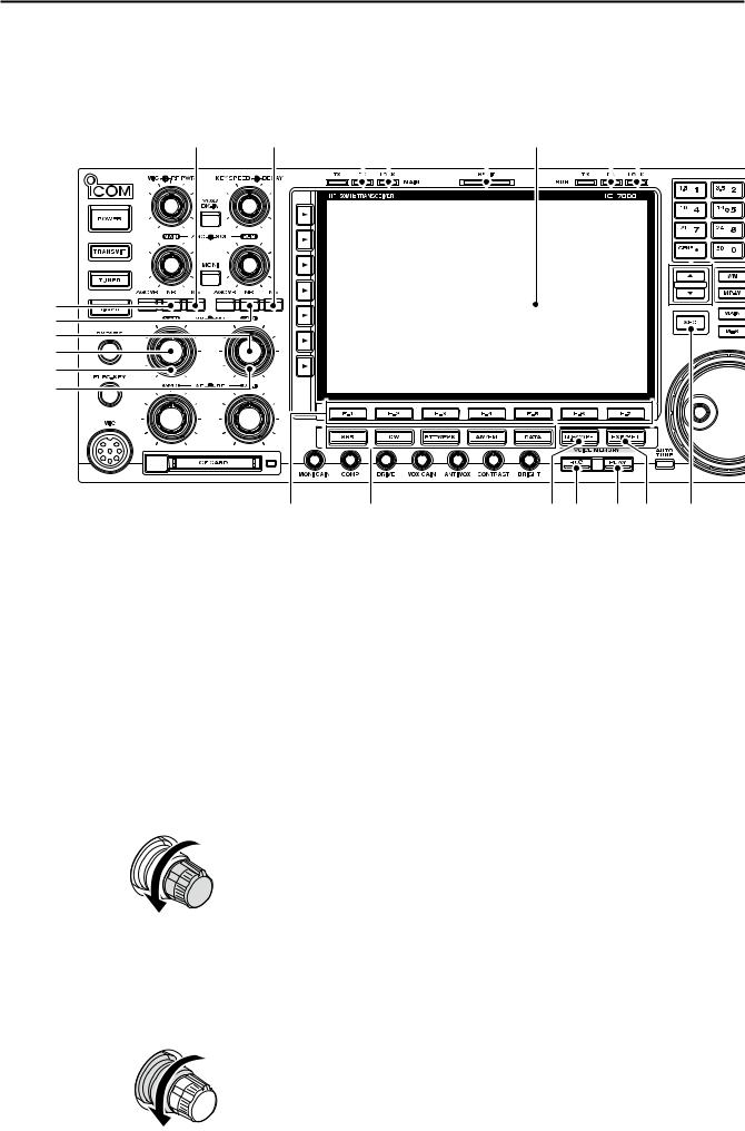
■ Front panel (continued)
@7 |
@8 |
@9 #0 |
#1 |
||||||||
|
|
|
|
|
|
|
|
|
|
|
|
|
|
|
|
|
|
|
|
|
|
|
|
|
|
|
|
|
|
|
|
|
|
|
|
!9
@0
@1
@2
@3 |
@4 |
@5
@6
#2 #3 #4
!9AGC CONTROL [AGC] (for MAIN band; p. 5-12) @0AGC CONTROL [AGC] (for SUB band; p. 5-12)
Adjusts the continuously-variable AGC circuit time constant.
•To use [AGC] control, push the appropriate band’s [AGC VR] ([AGC VR] indicator lights).

 Slow
Slow
Fast
@1AGC VOLUME SWITCH [AGC VR]
(for MAIN band; p. 5-12)
@2AGC VOLUME SWITCH [AGC VR]
(for SUB band; p. 5-12)
Push to toggle [AGC] control usage ON or OFF.
•Use [AGC] control to set the AGC time constant when switched ON.
•The [AGC VR] indicator above this switch lights green when the control is ON.
Turns the AGC function OFF when held down for 1 second.
@3AF CONTROL [AF] (inner control; for SUB band) @4AF CONTROL [AF] (inner control; for MAIN band)
Varies the audio output level of the speaker or headphones.
Audio output increases
Audio output decreases
1-4
@5RF GAIN CONTROL [RF]
(outer control; for MAIN band; p. 3-9)
@6RF GAIN CONTROL [RF]
(outer control; for SUB band; p. 3-9) Adjusts the RF gain level.
 While rotating the RF gain control, you may hear noise. This comes from the DSP unit and does
  not indicate a malfunction.
Sensitivity increases
Sensitivity decreases
@7SQUELCH CONTROL [SQL]
(outer control; for MAIN band; p. 3-9)
@8SQUELCH CONTROL [SQL]
(outer control; for SUB band; p. 3-9)
Adjusts the squelch threshold level. The squelch removes noise output from the speaker (closed condition) when no signal is received.
•The squelch is particularly effective for FM. It is also available for other modes.
•11 to 12 o’clock position is recommended for any setting of the [SQL] control.
|
Noise squelch |
|
|
Squelch |
|
|
Deep threshold |
S-meter |
|
Squelch |
|
|
squelch |
|
Shallow |
is open. |
|
|
|
|
|
Shallow |
Deep |

PANEL DESCRIPTION |
1 |
@9MULTI-FUNCTION SWITCHES
Push to select the functions indicated in the LCD display to the right of these switches.
•Functions vary depending on the operating condition.
Selects the antenna connector from ANT1, ANT2, ANT3 or ANT4 when pushed. (p. 10-2)
Displays antenna selection memory when held down for 1 second.
Turns the speech compressor ON or OFF in SSB mode. (p. 6-5)
Switches the narrow, middle or wide compression when held down for 1 second.
What is the speech compressor?
The speech compressor compresses the transmitter audio input to increase the average audio output level, to increase talk power. This function is effective for long-distance com-
•When the receive antenna is activated, the munication or when propagation conditions are poor. antenna which is connected to [ANT4] is
used for receive only.
 When a transverter is in use, this [ANT]
  does not function and ‘TRV’ appears.
Selects RF power (Po), SWR, ALC, COMP, Vd or Id metering during transmit. (p. 3-10)
Switches the multi-function digital meter ON or OFF when held down for 1 second. (p. 3-10)
Selects one of 2 receive RF preamps or bypasses them. (p. 5-10)
•“P. AMP1” activates 10 dB preamp.
•“P. AMP2” activates 16 dB high-gain preamp.
What is the preamp?
The preamp amplifies received signals in the front end circuit to improve S/N ratio and sensitivity. Select “P. AMP1” or “P. AMP2” when receiving weak signals.
Turns the 1⁄4-speed tuning function ON or OFF in SSB data, CW, RTTY and PSK modes. (p. 3-6)
• 1⁄4 function sets dial rotation to 1⁄4 of normal speed for fine tuning.
Switches between the tone encoder, tone squelch function and no-tone operation when pushed in FM mode. (pp. 4-32, 4-33)
Enters the tone set mode when held down for 1 second in FM mode. (pp. 4-32, 4-33)
Switches the voice squelch control function ON or OFF; useful for scanning. (p. 9-3)
#0TRANSMIT INDICATOR [TX] (for MAIN band) #1TRANSMIT INDICATOR [TX] (for SUB band)
Lights red while transmitting.
Selects 6 dB, 12 dB or 18 dB attenuator when pushed. (p. 5-10)
•SUB band’s [TX] indicator lights only when in split operation.
Selects 3 dB, 6 dB, 9 dB, 12 dB, 18 dB, #2ANTI VOX CONTROL [ANTI VOX] (p. 6-2)
or 21 dB attenuator when held down for Adjusts the VOX deactivate level to prevent un-
1 second. (p. 5-10)
What is the attenuator?
The attenuator prevents a desired signal from distorting when very strong signals are near the desired frequency, or when very strong electric fields, such as from a broadcasting station, are near your location.
wanted VOX activation from the speaker audio.
|
Increases |
Push |
cut-off level |
Decreases cut-off level
#3LCD CONTRAST CONTROL [CONTRAST]
Activates and selects fast, middle or slow AGC time constant when pushed. (p. 5-12)
• In FM mode, only “FAST” is available.
Enters the AGC set mode when held down for 1 second. (p. 5-12)
 AGC time constant can be set between 0.1 to 8.0
 second (depends on mode), or turned OFF . When
 AGC is “OFF,” the S-meter does not function.
What is the AGC?
The AGC controls receiver gain to produce a constant audio output level, even when the received signal strength varies dramatically. Select “FAST” for tuning and then select “MID” or “SLOW” depending on the receiving condition.
1-5
Adjusts the LCD contrast.
|
High |
Push |
contrast |
Low contrast
#4LCD BRIGHTNESS CONTROL [BRIGHT]
Adjusts the LCD brightness.
Bright
Push
Dark
1 PANEL DESCRIPTION
■ Front panel (continued)
$1 |
$2 |
$3$5 |
$7 |
$8 |
$4$6 |
$9 |
||||||||
|
|
|
|
|
|
|
|
|
|
|
|
|
|
|
|
|
|
|
|
|
|
|
|
|
|
|
|
|
|
#5
#6
#7
#8
#9 $0
%0 |
%1 |
%2%3 %4%5 %6 |
#5NOISE REDUCTION SWITCH [NR] (for MAIN band; p. 5-19)
#6NOISE REDUCTION SWITCH [NR] (for SUB band; p. 5-19)
Push to switch the DSP noise reduction ON or OFF.
•The [NR] indicator above this switch lights green when the function is activated.
#7NOISE REDUCTION LEVEL CONTROL [NR]
(inner control; for SUB band; p. 5-19)
#8NOISE REDUCTION LEVEL CONTROL [NR]
(inner control; for MAIN band; p. 5-19)
Adjusts the DSP noise reduction level when the noise reduction is in use. Set for maximum readability.
• To use this control, push the appropriate band’s [NR].
 Increases
Decreases
#9NOISE BLANKER CONTROL [NB] (outer control; for MAIN band; p. 5-18)
$0NOISE BLANKER CONTROL [NB] (outer control; for SUB band; p. 5-17)
Adjust the noise blanker threshold level.
•To use this control, push appropriate band’s [NB] switch.
 Deep
Deep
Shallow
1-6
$1NOISE BLANKER SWITCH [NB] (for MAIN band; p. 5-18)
$2NOISE BLANKER SWITCH [NB] (for SUB band; p. 5-18)
Switches the noise blanker ON or OFF when pushed. The noise blanker reduces pulse-type noise such as that generated by automobile ignition systems. This function cannot be used for FM, or non-pulse-type noise.
•The [NB] indicator above this switch lights green while the function is activated.
Enters blank-width set mode when held down for 1 second.
$3RECEIVE INDICATOR [RX] (for MAIN band) $4RECEIVE INDICATOR [RX] (for SUB band)
Lights green while receiving a signal and when the squelch is open.
$5LOCK INDICATOR [LOCK] (for MAIN band; p. 5-19) $6LOCK INDICATOR [LOCK] (for SUB band; p. 5-19)
Lights when the dial lock function is activated.
$7SPLIT OPERATION INDICATOR [SPLIT]
Lights during split frequency operation.
$8LCD FUNCTION DISPLAY (p. 1-15)
Shows the operating frequency, function switch menus, spectrum scope screen, memory channel screen, set mode settings, etc.

$9MEMORY UP/DOWN SWITCHES [Y]/[Z] (p. 8-2) Push to select the desired memory channel.
•Memory channels can be selected both in VFO and memory modes.
%0LCD FUNCTION SWITCHES [F-1]–[F-7]
Push to select the function indicated in the LCD display above these switches.
• Functions vary depending on the operating condition.
%1MODE SWITCHES
Selects the desired mode. (p. 3-8)
•Announces selected mode via the speech synthesizer.
(p. 12-17)
Selects USB or LSB modes alternately.
Selects CW or CW-R (CW reverse) modes alternately.
Switches between RTTY and PSK mode.
Switches RTTY or RTTY-R (RTTY reverse) mode when held down for 1 second in RTTY mode.
Switches PSK or PSK-R (PSK reverse) mode when held down for 1 second in PSK mode.
Selects AM or FM modes alternately.
Selects SSB, AM or FM data mode
(USB-D, LSB-D, AM-D, FM-D) when pushed in SSB, AM or FM mode, respectively.
Switches D1, D2 or D3 when held down for 1 second.
%2MINI SPECTRUM SCOPE SWITCH [M.SCOPE]
(p. 5-4)
Push to turn ON or OFF the mini spectrum scope screen.
•The mini spectrum scope screen can be displayed with another screen, such as memory or set mode screen, simultaneously.
Hold down for 1 second to turn ON the spectrum scope screen.
%3VOICE MEMORY RECORD SWITCH [REC]
Push to store the previous received signal for the preset time period. (p. 7-7)
•The preset time period can be set in the voice set mode. (p. 7-13)
Hold down for 1 second to record a QSO (Communication) audio onto a memory device. (p. 7-2)
•Hold down this switch for 1 second again to stop recording.
•The recorded memory device can be changed in the voice set mode. (p. 7-13)
PANEL DESCRIPTION |
1 |
%4VOICE MEMORY PLAY BACK SWITCH [PLAY]
(p. 7-8)
Push to playback the selected voice memory in the RX memory screen for the preset time period.
•When the RX memory screen is not displayed, the previously recorded audio is played back for the preset time period.
Hold down for 1 second to playback all of the selected voice memory in the RX memory screen.
•When the RX memory screen is not displayed, all of the previously recorded audio is played back.
%5EXIT/SET SWITCH [EXIT/SET]
Push to exit, or return to the previous screen indication during spectrum scope, memory, scan or set mode screen display.
Displays set mode menu screen when held down for 1 second.
%6TRANSMIT FREQUENCY CHECK SWITCH [XFC]
(p. 6-6)
Monitors the transmit frequency (including ∂TX frequency offset) when held down during split frequency operation.
•While holding down this switch, the transmit frequency can be changed with the main dial, keypad, memo pad or [Y]/[Z] switches.
•When the split lock function is turned ON, pushing [XFC] cancels the dial lock function. (p. 6-7)
1-7
1 PANEL DESCRIPTION
■ Front panel (continued)
%7%8 %9 ^0^1 ^2^3
|
|
|
|
^4 |
|
|
|
|
^5 |
|
|
|
|
^6 |
|
|
|
|
^7 |
|
|
|
|
^8 |
|
|
|
|
^9 |
&0&1&2 |
&4 |
&5&6&3&8 |
&9 |
&7 |
%7MEMO PAD-WRITE SWITCH [MP-W] (p. 8-7) Programs the selected readout frequency and operating mode into a memo pad.
•The 5 most recent entries remain in memo pads.
•The memo pad capacity can be expanded from 5 to 10 in set mode. (p. 12-18)
%8VFO/MEMORY SWITCH [V/M]
Switches the selected readout operating mode between the VFO and memory when pushed.
(pp. 3-3, 8-2)
Transfers the memory contents to VFO when held down for 1 second. (p. 5-5)
%9KEYPAD
Pushing a key selects the operating band.
•[GENE•.] selects the general coverage band.
Pushing the same key 2 or 3 times calls up other stacked frequencies in the band. (p. 3-4)
•Icom’s triple band stacking register memorizes 3 frequencies in each band.
After pushing [F-INP•ent], enters a frequency or memory channel. Pushing [F-INP•ent] or [Y/[Z] is necessary to end. (pp. 3-5, 8-2)
•e.g. to enter 14.195 MHz, push [F-INP] [1.8•1] [10•4] [GENE •] [1.8•1] [28•9] [14•5] [F-INP•ent].
^0MEMORY WRITE SWITCH [MW] (p. 8-4)
Stores the selected readout frequency and operating mode into the displayed memory channel when held down for 1 second.
•This function is available both in VFO and memory modes.
^1MEMO PAD-READ SWITCH [MP-R] (p. 8-7) Each push calls up a frequency and operating mode in a memo pad. The 5 (or 10) most recently programmed frequencies and operating modes can be recalled, starting from the most recent.
•The memo pad capacity can be expanded from 5 to 10 in set mode. (p. 12-18)
^2FILTER SWITCH [FILTER] (for MAIN band; p. 5-14) ^3FILTER SWITCH [FILTER] (for SUB band; p. 5-14)
Selects one of 3 IF filter settings.
Enters the filter set screen when held down for 1 second.
^4AUDIO PEAK FILTER/TWIN PEAK FILTER SWITCH [APF/TPF] (for MAIN band)
^5AUDIO PEAK FILTER/TWIN PEAK FILTER SWITCH [APF/TPF] (for SUB band)
Push to turn the audio peak filter ON or OFF during CW mode operation. (p. 4-6)
Push to turn the twin peak filter ON or OFF during RTTY mode operation. (p. 4-14)
•“ ” appears when audio peak filter is in use.
•“ ” appears when twin peak filter is in use.
During CW mode operation, hold down for 1 second to select the APF passband width from 80, 160 and 320 Hz. (p. 4-6)
1-8

^6NOTCH SWITCH [NOTCH] (for SUB band; p. 5-20) ^7NOTCH SWITCH [NOTCH] (for MAIN band; p. 5-20)
Switches the notch function between auto, manual or OFF in SSB and AM modes.
Turns the manual notch function ON or OFF when pushed in CW, RTTY and PSK31 mode.
Turns the auto notch function ON or OFF when pushed in FM mode.
•“ ” appears when auto notch is in use.
•“ ” appears when manual notch is in use.
Switches the manual notch characteristics from wide, middle or narrow when held down for 1 second.
What is the notch function?
The notch function eliminates unwanted CW or AM carrier tones while preserving the desired voice signal. The DSP circuit automatically adjusts the filtering frequency to effectively eliminate unwanted tones.
^8DUALWATCH SWITCH [DUALWATCH] (p. 5-17)
Turns the dualwatch function ON or OFF when pushed.
Turns the dualwatch function ON, and equalizes the main/sub readout frequency to the sub/main readout when held down for 1 second. (Quick dualwatch function)
•The quick dualwatch function can be turned OFF using set mode. (p. 12-15)
^9SPLIT SWITCH [SPLIT] (p. 6-6)
Push to turn ON or OFF the split function.
Hold down for 1 second to turn the split function ON and equalizes the sub readout frequency to the main readout in non-FM modes, and then sets the sub readout for frequency input mode.
(Quick split function)
•In the FM mode, the sub readout frequency is shifted the preset frequency offset from the main readout frequency. (pp. 12-15, 12-16)
•The quick split function can be turned OFF using set mode. (p. 12-15)
After inputting a frequency offset, push to turn the split function ON, and the sub readout frequency is shifted the amount of frequency from the main readout frequency.
&0MAIN BAND ACCESS SWITCH [MAIN]
Selects the main readout.
•The main readout frequency is clearly displayed. The sub readout functions only during split operation or dualwatch.
&1MAIN/SUB EQUALIZING SWITCH [M=S]
Hold down for 1 second to equalize the sub readout frequency to the main readout frequency.
PANEL DESCRIPTION |
1 |
&2AUTOMATIC TUNING SWITCH [AUTO TUNE]
(for MAIN band)
&3AUTOMATIC TUNING SWITCH [AUTO TUNE]
(for SUB band)
Turns the automatic tuning function ON or OFF in CW and AM modes.
IMPORTANT!
When receiving a weak signal, or receiving a signal with interference, the automatic tuning function may tune the receiver to an undesired signal.
&4MAIN DIAL
Changes the displayed frequency (main band), selects set mode setting, etc.
&5MAIN/SUB CHANGE SWITCH [CHANGE]
Switches the frequency and selected memory channel between main and sub readouts when pushed.
•Switches between transmit frequency and receive frequency when the split frequency function is ON. (p. 6-6)
&6LOCK SWITCH [LOCK] (for MAIN band; p. 5-19) &7LOCK SWITCH [LOCK] (for SUB band; p. 5-19)
Push to switch the dial lock function ON or OFF.
&8SUB BAND ACCESS SWITCH [SUB]
Selects the sub readout.
•The sub readout frequency is clearly displayed. The main readout functions only during split operation or dualwatch.
&9SUB DIAL
Changes the displayed frequency in sub band.
1-9

1 PANEL DESCRIPTION
■ Front panel (continued)
*0*1 |
*3*4 |
*2 |
*5
*7
*8
*6

 *9
*9 

 (0
(0
(1
(2
(3
(4
(5(6(7 (8
*0RIT/∂TX CONTROL [RIT/∂TX] (pp. 5-11, 6-4) |
PBT2 |
|
Shifts the receive and/or transmit frequency without |
||
PBT1 |
||
changing the transmit and/or receive frequency. |
||
|
||
• Rotate the control clockwise to increase the frequency, |
|
|
or rotate the control counterclockwise to decrease the |
|
|
frequency. The RIT or ∂TX functions must be ON. |
|
•The shift frequency range is ±9.999 kHz in 1 Hz steps
(or ±9.99 kHz in 10 Hz steps).
– |
+ |
Frequency increases
Frequency  decreases
*1PASSBAND TUNING CONTROLS [TWIN PBT]
(for MAIN band; p. 5-13)
*2PASSBAND TUNING CONTROLS [TWIN PBT]
(for SUB band; p. 5-13)
Adjusts the receiver’s IF filter “passband width” via the DSP.
•Passband width and shift frequency are displayed in the multi-function display.
•Hold down [PBT CLEAR] for 1 second to clear the PBT settings.
•The adjustment range is half of the passband width, and the value is adjustable in 25 Hz steps for the SSB/ CW/RTTY/PSK modes, and 100 Hz steps for the AM mode.
What is the PBT control?
High cut |
Center |
Low cut |
*3PBT CLEAR SWITCH [PBT CLEAR]
(for MAIN band; p. 5-13)
*4PBT CLEAR SWITCH [PBT CLEAR]
(for SUB band; p. 5-13)
Clears the PBT settings when held down for 1 second.
•The [PBT CLEAR] indicator above this switch lights when PBT is in use.
The PBT function electronically modifies the IF passband width to reject interference. This transceiver uses the DSP circuit for the PBT function.
1-10
*5DIGITAL RF SELECTOR CONTROL [DIGI-SEL]
(for MAIN band; p. 5-20)
*6DIGITAL RF SELECTOR CONTROL [DIGI-SEL]
(for SUB band; p. 5-20)
Adjusts the digital RF selector center frequency.
•The control can be reassigned as the audio peak filter adjustment (p. 12-19)
Higher frequency
Lower frequency
*7DIGITAL RF SELECTOR SWITCH [DIGI-SEL]
(for MAIN band; p. 5-20)
*8DIGITAL RF SELECTOR SWITCH [DIGI-SEL]
(for SUB band; p. 5-20)
Turns the digital RF preselector ON or OFF.
•The [DIGI-SEL] indicator lights green when the preselector is in use.
*9MANUAL NOTCH FILTER CONTROL [NOTCH]
(for SUB band; outer control; p. 5-20)
(0MANUAL NOTCH FILTER CONTROL [NOTCH]
(for MAIN band; outer control; p. 5-20)
Varies the “valley” frequency of the manual notch filter to reject an interfering signal while the manual notch function is ON.
• Notch filter center frequency:
SSB |
: –1060 Hz to 4040 Hz |
CW |
: CW pitch freq. + 2540 Hz to CW pitch freq. |
|
–2540 Hz |
AM |
: –5100 Hz to 5100 Hz |
|
Higher |
|
frequency |
Lower frequency
(1CW PITCH CONTROL [CW PITCH] (p. 4-5) Shifts the received CW audio pitch and the CW side tone pitch without changing the operating frequency.
High frequency
Low frequency
PANEL DESCRIPTION |
1 |
(2RIT SWITCH [RIT] (p. 5-11)
Turns the RIT function ON or OFF when pushed.
•Use [RIT/∂TX] control to vary the RIT frequency.
Adds the RIT shift frequency to the operating frequency when held down for 1 second.
What is the RIT function?
Receiver incremental tuning (RIT) shifts the receive frequency without shifting the transmit frequency.
This is useful for fine tuning stations calling you on off-fre- quency or when you prefer to listen to slightly differentsounding voice characteristics, etc.
(3∂TX SWITCH [∂TX] (p. 6-4)
Turns the ∂TX function ON or OFF when pushed.
•Use [RIT/∂TX] control to vary the ∂TX frequency.
Adds the ∂TX shift frequency to the operating frequency when held down for 1 second.
What is the ∂TX function?
∂TX shifts the transmit frequency without shifting the receive frequency. This is useful for simple split frequency operation in CW, etc.
(4CLEAR SWITCH [CLEAR] (pp. 5-11, 6-4)
Clears the RIT/∂TX shift frequency when held down for 1 second or when pushed momentarily, depending on the quick RIT/∂TX clear function setting (p. 12-18).
(5QUICK TUNING SWITCH [TS] (for MAIN band) (6QUICK TUNING SWITCH [TS] (for SUB band)
Turns the quick tuning step ON or OFF. (p. 3-6)
•While the quick tuning indicator, “Z,” is displayed above the frequency indication, the frequency can be changed in programmed kHz steps.
•0.1, 1, 5, 9, 10, 12.5, 20 and 25 kHz steps are available for each operating mode independently.
When the quick tuning step is OFF, held down for 1 second to turn the 1 Hz tuning step ON or OFF. (p. 3-7)
When the quick tuning step is ON, hold down for 1 second to enter quick tuning step set mode. (p. 3-6)
(7SPEECH SWITCH [SPEECH]
(for MAIN band; p. 13-3)
(8SPEECH SWITCH [SPEECH]
(for SUB band; p. 13-3)
Push to announce the S-meter indication and the selected readout frequency.
The selected operating mode is additionally announced when held down for 1 second.
1-11

1 PANEL DESCRIPTION
■ Rear panel
q w e
ANT 1 |
ANT 2 |
ANT 3 |
r t y u i o !0 !1
OUT |
IN |
X-VERTER |
OUT |
IN |
|
RX ANT |
|
|
RX ANT |
|
B |
|
|
A |
|
|
|
I |
|
|
|
|
|
!2 |
ANT 4 |
|
AC |
|
|
|
|
|
|
!3 |
|
|
|
|
|
S/P DIF |
REF I/O |
DC OUT |
EXT |
|
|
|
ALC |
|
B |
A |
|
EXT-SP |
EXT-DISPLAY |
|
RS-232C |
|
|
10MHz |
15V |
|
|
|
|
|
||||||
KEY BOARD |
REMOTE |
OUT |
IN |
-10dBm |
MAX1A |
METER KEYPAD |
KEY |
RELAY |
ALC |
ADJ |
ACC 2 |
ACC 1 |
ACC 2 |
ACC 1 |
SUB MAIN |
#3 |
#4 #2 |
#1 #0 @9@8 @7 @6@5@4@3@2@1@0!9 !8 !7 !6!5!4 |
q ANTENNA CONNECTOR 1 [ANT 1] (p. 2-4) w ANTENNA CONNECTOR 2 [ANT 2] (p. 2-4) e ANTENNA CONNECTOR 3 [ANT 3] (p. 2-4) r ANTENNA CONNECTOR 4 [ANT 4] (p. 2-4)
Accept a 50 Ω antenna with a PL-259 plug connector.
t GROUND TERMINAL [GND] (p. 2-3)
Connect this terminal to a ground to prevent electrical shocks, TVI, BCI and other problems.
y CIRCUIT BREAKER
Cuts off the AC input when over-current occurs.
u RECEIVE ANTENNA B OUT [RX ANT B– OUT] i RECEIVE ANTENNA B IN [RX ANT B– IN]
Located between the transmit/receive switching circuit and receiver’s RF stage in SUB band (MAIN band during split operation).
Connects an external unit, such as preamplifier or RF filter, using BNC connectors, if desired.
When no external unit is connected, [RX ANT B– OUT] and [RX ANT B– IN] must be shorted with the supplied coaxial cable. (p. 2-2)
[RX ANT A/B]
Receiver |
|
IN |
OUT |
Transmitter |
Transmit/Receive |
|
switching circuit |
o TRANSVERTER CONNECTOR [X-VERTER]
(p. 2-5)
External transverter input/output connector. Activated by voltage applied to [ACC 2] pin 6, or when the transverter function is in use. (pp. 1-14, 4-6)
!0RECEIVE ANTENNA A OUT [RX ANT A– OUT] !1RECEIVE ANTENNA A IN [RX ANT A– IN]
Located between the transmit/receive switching circuit and receiver’s RF stage in MAIN band (SUB band during split operation).
Connects an external unit, such as preamplifier or RF filter, using BNC connectors, if desired.
When no external unit is connected, [RX ANT A– OUT] and [RX ANT A– IN] must be shorted with the supplied coaxial cable. (p. 2-2)
!2MAIN POWER SWITCH [I/O] (p. 3-2) Turns the internal power supply ON or OFF.
!3AC POWER SOCKET [AC] (p. 2-4)
Connects the supplied AC power cable to an AC line-voltage receptacle.
!4EXTERNAL SPEAKER JACK MAIN [EXT-SP MAIN]
(p. 2-5)
!5EXTERNAL SPEAKER JACK SUB [EXT-SP SUB]
(p. 2-5)
Connects an external speaker (4–8 Ω), if desired.
1-12

!6ACCESSORY SOCKET 1 A [ACC 1–A] !7ACCESSORY SOCKET 2 A [ACC 2–A] !8ACCESSORY SOCKET 1 B [ACC 1–B] !9ACCESSORY SOCKET 2 B [ACC 2–B]
Enable connection of external equipment such as a linear amplifier, an automatic antenna selector/ tuner, a TNC for data communications, etc.
• See page 1-14 for socket information.
@0ALC LEVEL ADJUSTMENT POT [ALC ADJ]
Adjusts the ALC levels.
No adjustment is required when the ALC output level of the connected non-Icom linear amplifier is 0 to –4 V DC.
@1ALC INPUT JACK [ALC] (p. 2-7)
Connects to the ALC output jack of a non-Icom linear amplifier.
@2T/R CONTROL JACK [RELAY] (p. 2-7)
Goes to ground when transmitting to control an external unit, such as a non-Icom linear amplifier.
NOTE: T/R control voltage and current must be lower than 16 V DC/0.5 A with Reed switching, or 250 V AC/200 mA with MOS-FET switching.
@3STRAIGHT KEY JACK [KEY] (p. 2-4)
Accepts a straight key or external electronic keyer with 1⁄4 inch standard plug.
•[ELEC-KEY] on the front panel can be used for a straight key or external electronic keyer. Deactivate the internal electronic keyer in keyer set mode. (p. 4-12)
_
+
@4EXTERNAL KEYPAD JACK [EXT KEYPAD]
(p. 2-6)
Connects an external keypad for direct voice memory (p. 7-11), memory keyer (p. 4-8), RTTY memory (p. 4-16) or PSK memory (p. 4-24) transmission.
Transceiver mute control line (both transmit and receive) is also supported.
@5METER JACK [METER] (p. 2-6)
Outputs the receiving signal strength level signal, transmit output power, VSWR, ALC, speech compression, Vd or Id level for external meter indication.
@6DC OUTPUT JACK [DC OUT] (p. 2-6)
Outputs a regulated 14 V DC (approximately) for external equipment. Connected in parallel with 13.8 V outputs of [ACC 1] and [ACC 2]. (max. 1 A in total)
_ |
+ |
_
PANEL DESCRIPTION |
1 |
@7REFERENCE SIGNAL INPUT/OUTPUT
TERMINAL [REF I/O]
Inputs/outputs a 10 MHz reference signal.
@8S/P DIF INPUT TERMINAL [S/P DIF– IN] (p. 2-6) @9S/P DIF OUTPUT TERMINAL [S/P DIF– OUT]
(p. 2-6)
Connects external equipment that supports S/P DIF input/output.
#0CI-V REMOTE CONTROL JACK [REMOTE]
(p. 2-5)
Connects a PC via the optional CT-17 ci-v level converter for external control of the transceiver.
Used for transceive operation with another Icom
CI-V transceiver or receiver.
#1RS-232C TERMINAL [RS-232C] (p. 2-5) Connects an RS-232C cable, D-sub 9-pin to connect the IC-7800 to a PC.
Can be used for remotely control the IC-7800 without the optional CT-17, or for RTTY/PSK31 decoded signal output. The [RS-232C] interface is wired as a modem (DCE).
#2KEYBOARD CONNECTOR [KEYBOARD]
(p. 2-6)
Connects a USB (Universal Serial Bus) device that is a keyboard, mouse, hub or memory (USB flash drive).
#3EXTERNAL DISPLAY TERMINAL [EXT-DISPLAY] (p. 2-6)
Connects to an external display monitor.
• At least 800×600 pixel display is necessary.
#4ETHERNET CONNECTOR [LAN] (p. 16-6) Connects to a PC network through a LAN (Local Area Network).
About the [KEYBOARD] connector:
•Supported only USB flash drive, keyboard, mouse or hub.
•KEEP the transceiver power OFF when connecting or disconnecting a USB keyboard, mouse or hub.
•DO NOT connect the following devices:
-Two or more the same kind of USB devices. (Example: Two USB hubs or two USB mouses)
-Multimedia adapter
-USB HDD
-Larger than 32 GB USB flash drives
-Bluetooth® keyboard or mouse.
1-13
1 PANEL DESCRIPTION
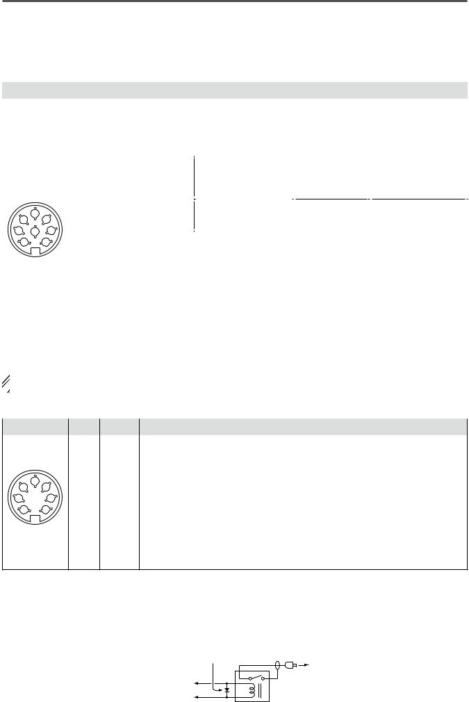
■ Accessory connector information
ACC 1 |
|
PIN No. |
NAME |
DESCRIPTION |
SPECIFICATIONS |
||||
|
|
|
|
|
|
|
|
|
|
|
|
|
|
|
|
|
|
“High level” |
: More than 2.4 V |
|
|
|
|
1 |
RTTY |
Controls RTTY keying |
“High level” |
: Less than 0.6 V |
|
|
|
|
|
|
|
|
|
Output current |
: Less than 2 mA |
|
|
|
|
|
|
|
|
|
|
|
|
|
|
2 |
GND |
Connects to ground. |
——— |
|
|
|
|
|
|
Connected in parallel with ACC 2 pin 2. |
|
||||
|
|
|
|
|
|
|
|
||
|
|
|
|
|
|
|
|
|
|
|
|
|
|
|
|
Input/output |
An external equipment |
Input voltage (High) |
: 2.0 V to 20.0 V |
|
|
|
|
|
|
controls the transceiver. |
Input voltage (Low) |
: –0.5 V to 0.8 V |
|
|
|
|
|
|
|
pin. |
When this pin goes low, |
||
|
|
|
|
3 |
SEND* |
Current flow |
: Max. 20 mA |
||
|
|
|
|
Connected in |
the transceiver transmits. |
|
|
||
|
2 |
|
|
|
|
parallel with |
The transceiver outputs |
Output voltage (Low) |
: Less than 0.1 V |
4 |
5 |
|
|
|
ACC 2 pin 3. |
a low signal to control ex- |
|||
|
|
|
|
|
ternal equipment. |
Current flow |
: Max. 200 mA |
||
1 |
8 |
|
3 |
|
|
|
|
|
|
|
|
|
Modulator input. |
Input impedance |
: 10 kΩ |
||||
6 |
|
7 |
|
4 |
MOD |
||||
|
|
Connects to a modulator. |
Output level |
: Approximately 100 mV rms |
|||||
|
|
|
|
|
|
||||
|
|
|
|
|
|
|
|
|
|
|
|
|
|
|
|
AF detector output. |
Output impedance |
: 4.7 kΩ |
|
|
|
|
|
5 |
AF |
Fixed level, regardless of [AF] position |
|||
|
|
|
|
Output level |
: 100–300 mV rms |
||||
|
|
|
|
|
|
in default settings. (see notes below) |
|
|
|
|
|
|
|
6 |
SQLS |
Squelch output. |
SQL open |
: Less than 0.3 V/5 mA |
|
|
|
|
|
Grounded when squelch opens. |
SQL closed |
: More than 6.0 V/100 µA |
|||
|
|
|
|
|
|
||||
|
|
|
|
|
|
|
|
|
|
|
|
|
|
7 |
13.8 V |
13.8 V output when power is ON. |
Output current |
: Max. 1 A |
|
|
|
|
|
Connected in parallel with ACC 2 pin 7. |
|||||
|
|
|
|
|
|
|
|
|
|
|
|
|
|
8 |
ALC |
ALC voltage input. |
Control voltage |
: –4 V to 0 V |
|
|
|
|
|
Connected in parallel with ACC 2 pin 5. |
Input impedance |
: More than 10 kΩ |
|||
|
|
|
|
|
|
||||
|
|
|
|
|
|
|
|
|
|
 NOTE: If the CW side tone level limit or beep level limit is in use, the CW side tone or beep tone decreases
  from the fixed level when the [AF] control is rotated above a specified level. (pp. 12-5, 12-6)
ACC 2 |
|
PIN No. |
NAME |
DESCRIPTION |
SPECIFICATIONS |
|||
|
|
|
|
|
|
|
|
|
|
|
|
|
1 |
8 V |
Regulated 8 V output. |
Output voltage |
: 8 V ±0.3 V |
|
|
|
|
Output current |
: Less than 10 mA |
|||
|
|
|
|
|
|
|
||
|
|
|
|
|
|
|
|
|
|
|
|
|
2 |
GND |
Same as ACC 1 pin 2. |
|
|
|
2 |
|
|
|
|
|
|
|
4 |
5 |
|
3 |
SEND* |
Same as ACC 1 pin 3. |
|
|
|
|
|
|
|
|
|
|
||
1 |
|
|
3 |
4 |
BAND |
Band voltage output. |
Output voltage |
: 0 V to 8.0 V |
6 |
|
7 |
|
(Varies with amateur band) |
||||
|
|
|
|
5 |
ALC |
Same as ACC 1 pin 8. |
|
|
|
|
|
|
|
|
|
|
|
|
|
|
|
6 |
TRV |
Activates [X-VERTER] input/output |
Input impedance |
: More than 10 kΩ |
|
|
|
|
when “HIGH” voltage is applied |
Input voltage |
: 2 V to 13.8 V |
||
|
|
|
|
|
|
|||
|
|
|
|
|
|
|
|
|
713.8 V Same as ACC 1 pin 7.
*When the SEND terminal controls the inductive load (such as a relay), a counter-electromotive force can cause the transceiver’s malfunction or damage. To prevent this, we recommend adding a switching diode, such as an “1SS133,” on the load side of the circuit to the counter-electromotive force absorption.
When the diode is added, a switching delay of the relay may occur. Be sure to check its switching action before operation.
[Example] |
ACC 1/2 |
Switching diode |
To a non-Icom |
|
|||
|
|
||
|
sockets |
|
linear amplifier |
|
|
|
|
|
e SEND |
|
|
|
u 13.8 V |
|
Relay |
|
|
|
1-14
PANEL DESCRIPTION |
1 |
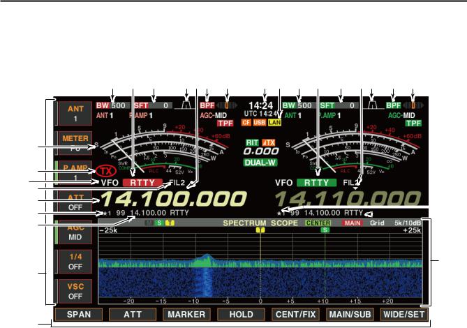
■ LCD display
!0 |
!1 |
!2 |
!3 |
!4 |
!5 |
!6 |
!7 |
!8 |
q w e |
tr y u |
i o q w e r t y u |
 !5
!5  !6
!6
!9
q BAND WIDTH INDICATOR (p. 5-13) Shows the passband width of the IF filter.
w MODE INDICATOR
Shows the selected mode.
e SHIFT FREQUENCY INDICATOR (p. 5-13) Shows the shift frequency of the IF filter.
r QUICK TUNING INDICATOR (p. 3-6)
Appears when the quick tuning step function is in use.
t PASSBAND WIDTH INDICATOR (p. 5-13) Graphically displays the passband width for twin PBT operation and center frequency for IF shift operation.
y BANDPASS FILTER INDICATOR
Appears when the narrow filter (500 Hz or less) is selected during CW, RTTY or PSK31 operation.
u RTTY TUNING INDICATOR
Shows the tuning level in RTTY mode.
i CLOCK READOUT
Shows the current time.
o LAN INDICATOR
Appears when the Remote station access the transceiver through the LAN. (An optional RS-BA1 is required.)
!0S/RF METER (p. 3-10)
Shows the signal strength while receiving. Shows the relative output power, SWR, ALC or compression levels while transmitting.
!1TX INDICATOR
Indicates the frequency readout for transmit.
!2VFO/MEMORY CHANNEL INDICATOR (p. 3-3)
Indicates the VFO mode or selected memory channel number.
!3IF FILTER INDICATOR
Shows the selected IF filter number.
!4FREQUENCY READOUTS
Shows the operating frequency.
• Gray characters are used for non-active readout.
!5SELECT MEMORY CHANNEL INDICATOR (p. 9-7) Indicates the displayed memory channel is set as a select memory channel.
The desired memory channels can be assigned to 3 select groups, for fast, convenient scanning.
!6MEMORY CHANNEL READOUTS
Shows the selected memory channel contents in
VFO mode.
Shows the VFO contents in memory mode.
!7MULTI-FUNCTION SWITCH GUIDE
Indicates the function of the multi-function switches.
!8LCD FUNCTION SWITCH GUIDE
Indicates the function of the LCD function switches ([F-1] – [F-7]).
!9MULTI-FUNCTION SCREEN
Shows the screens for the multi-function digital meter, spectrum scope, audio scope, voice recorder, memory channel, scan, memory keyer, RTTY decoder, PSK decoder, IF filter selection or set modes, etc.
1-15

1 PANEL DESCRIPTION
■ Screen menu arrangement
The following screens can be selected from the start up screen. Choose the desired screen using the following chart.
•Spectrum scope screen (p. 5-2)
•Voice recorder screen (p. 7-2)
•Memory keyer screen (CW mode; p. 4-8)
•RTTY decoder screen (p. 4-13)
Pushing [EXIT/SET] several times returns to the start up screen. See page 12-3 for set mode arrangement.
•PSK31 decoder screen (p. 4-21)
•Memory channel screen (p. 8-3)
•Scan screen (VFO mode; p. 9-4)
•Scan screen (Memory mode; p. 9-6)
•Audio scope (p. 5-21)
•Set mode menu screen (p. 12-2)
1-16

INSTALLATION AND CONNECTIONS |
Section 2 |
■Unpacking… ……………………………………………………………… 2-2
■Antenna jumper cable connection… …………………………………… 2-2
■Selecting a location… …………………………………………………… 2-2
■Rack mounting handle attachment……………………………………… 2-2
■Grounding… ……………………………………………………………… 2-3
■Antenna connection… …………………………………………………… 2-3
■CF (Compact Flash) memory card……………………………………… 2-3
■Required connections… ………………………………………………… 2-4 D Front panel……………………………………………………………… 2-4 D Rear panel… …………………………………………………………… 2-4
■Advanced connections…………………………………………………… 2-5 D Front panel……………………………………………………………… 2-5 D Rear panel—1… ……………………………………………………… 2-5 D Rear panel—2… ……………………………………………………… 2-6
■Linear amplifier connections… ………………………………………… 2-7 D Connecting the IC-PW1/EURO… …………………………………… 2-7 D Connecting a non-Icom linear amplifier……………………………… 2-7
■Transverter jack information……………………………………………… 2-8
■FSK and AFSK connections……………………………………………… 2-8 D When using the ACC socket or the microphone connector… …… 2-8
■Microphones (options)… ………………………………………………… 2-9 D SM-50…………………………………………………………………… 2-9 D SM-30…………………………………………………………………… 2-9 D HM-36…………………………………………………………………… 2-10
■Microphone connector information……………………………………… 2-10
 CAUTION: The transceiver weights approximately 25 kg (55
  lb). Always have two people available to carry, lift or turn
  over the transceiver.
2-1

2 INSTALLATION AND CONNECTIONS
■ Unpacking
After unpacking, immediately report any damage to the delivering carrier or dealer. Keep the shipping cartons.
For a description and a diagram of accessory equipment included with the IC-7800, see ‘Supplied accessories’ on p. iii of this manual.
■ Antenna jumper cable connection
Connect the supplied coaxial cable (terminated with BNC connectors) between [RX ANT A— IN] and [RX ANT A— OUT], and, [RX ANT B— IN] and [RX ANT B— OUT], respectively.
When connecting an external filter unit, pre-amplifier, etc., connect the unit between [RX ANT A/B— IN] and [RX ANT A/B— OUT] connectors.
■ Selecting a location
Select a location for the transceiver that allows adequate air circulation, free from extreme heat, cold, or vibrations, and away from TV sets, TV antenna elements, radios and other electromagnetic sources.
The base of the transceiver has an adjustable stand for desktop use. Set the stand to one of two angles depending on your operating preference.
■ Rack mounting handle attachment
Remove the four screws from both sides of the front panel and the two screws from both sides of the side panel, then attach the rack mounting handles to the sides of the transceiver using the supplied screws.
M4×15
M4×9
2-2
INSTALLATION AND CONNECTIONS |
2 |
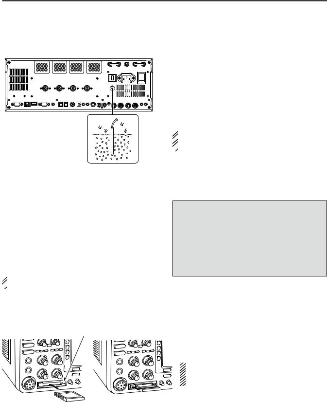
■ Grounding
To prevent electrical shock, television interference
(TVI), broadcast interference (BCI) and other problems, ground the transceiver through the GROUND terminal on the rear panel.
For best results, connect a heavy gauge wire or strap to a long earth-sunk copper rod. Make the distance between the [GND] terminal and ground as short as possible.
 R WARNING! NEVER connect the [GND]
  terminal to a gas or electric pipe, since the connection
  could cause an explosion or electric shock.
■ Antenna connection
For radio communications, the antenna is of critical importance, along with output power and receiver sensitivity. Select antenna(s), such as a well-matched 50 Ω antenna, and feedline. We recommend 1.5:1 or better of Voltage Standing Wave Ratio (VSWR) for your desired band. Of course, the transmission line should be a coaxial cable.
When using 1 antenna, use the [ANT1] connector.
 CAUTION: Protect your transceiver from light-
  ning by using a lightning arrestor.
Antenna SWR
Each antenna is tuned for a specified frequency range and SWR may be increased out-of-range. When the SWR is higher than approximately 2.0:1, the transceiver’s power drops to protect the final transistors. In this case, an antenna tuner is useful to match the transceiver and antenna. Low SWR allows full power for transmitting. The IC-7800 has an SWR meter to monitor the antenna SWR continuously.
■ CF (Compact Flash) memory card
Read/write indicator |
Insert the supplied CF (Compact Flash) memory |
|
card into the CF memory card slot. |
|
• To remove the CF memory card, push-in the button, lo- |
|
cated at left hand side of the slot. |
|
Make sure to install the memory card correctly. |
|
NEVER insert or remove the CF memory card |
|
when the read/write indicator lights or blinks. |
2-3

2 INSTALLATION AND CONNECTIONS
■ Required connections
D Front panel
CW key
A straight or bug key can be used when the internal electronic keyer is turned OFF in keyer set mode. (p. 4-12)
Microphones (pp. 2-9, 2-10)
Optional |
Optional |
Optional |
SM-50 |
SM-30 |
HM-36 |
D Rear panel
Antenna 1, 2, 3, 4 (p. 2-3)
[Example]: ANT1 for 1.8–18 MHz bands, ANT 2 for 21–28 bands ANT3 for 50 MHz band, ANT 4 for receive antenna.
NOTE: Attach the supplied antenna connector cap when no antenna or external equipment is connected.
A jumper cable is connected.
|
|
|
OUT |
IN |
X-VERTER |
OUT |
IN |
|
|
|
|
RX ANT |
|
|
RX ANT |
|
|
|
|
B |
|
|
A |
|
|
|
|
|
|
I |
|
ANT 1 |
ANT 2 |
ANT 3 |
ANT 4 |
|
AC |
|
|
|
|
|
|
|
S/P DIF |
REF I/O |
DC OUT |
EXT |
|
|
|
ALC |
|
B |
A |
|
EXT-SP |
EXT-DISPLAY |
KEY BOARD |
RS-232C |
REMOTE |
OUT |
10MHz |
15V |
KEY |
RELAY |
ALC |
ACC 2 |
ACC 1 |
||||||
IN |
-10dBm |
MAX1A |
METER KEYPAD |
ADJ |
ACC 1 |
ACC 2 |
SUB MAIN |
Ground
(p. 2-3)
Use the heaviest gauge Straight key wire or strap available and  make the connection as


 short as possible.


Grounding prevents electrical shocks, TVI and other problems.
AC outlet
RWARNING!
Use the supplied AC power cable only.
2-4
Loading...