


INSTRUCTION MANUAL
VHF/UHF FM TRANSCEIVER
i91A
VHF/UHF DIGITAL TRANSCEIVER
i91AD
This device complies with Part 15 of the FCC Rules. Operation is subject to the following two conditions: (1) this device may not cause harmful interference, and (2) this device must accept any interference received, including interference that may cause undesired operation.
WARNING: MODIFICATION OF THIS DEVICE TO RECEIVE CEL-
LULAR RADIO TELEPHONE SERVICE SIGNALS IS PROHIBITED
UNDER FCC RULES AND FEDERAL LAW.
Y The above photo shows IC-91AD.

FOREWORD
Thank you for purchase of this fine Icom product. We understand you have a choice of many different radios in the market place. Many hours of research and development went into the design of your IC-91A/91AD, following Icom’s philosophy of “technology first.”
The IC-91A/91AD VHF/UHF FM TRANSCEIVER is designed with Icom’s superior technology and craftsmanship combining traditional analog technologies with the new digital D-STAR technologies for a balanced packaged.
With proper care, this product should provide you with years of trouble-free operation. We want to take a couple of moments of your time to thank you for making your IC-91A/91AD your radio of choice, and hope you agree with Icom’s philosophy of “technology first.”
EXPLICIT DEFINITIONS
WORD |
DEFINITION |
Personal injury, fire hazard or electric shock R WARNING! may occur.
CAUTION Equipment damage may occur.
NOTE
Recommended for optimum use. No risk of personal injury, fire or electric shock.
FEATURES
DV mode (Digital voice + Low-speed data communication) operation is ready
–GPS receiver connection
–Text message and call sign exchange
(Optional UT-121 DIGITAL UNIT is required for IC-91A.)
Simple band scope
Dualwatch operation
Optional PC remote control
IMPORTANT
READ ALL INSTRUCTIONS carefully and completely before using the transceiver.
SAVE THIS INSTRUCTION MANUAL— This instruction manual contains important operating instructions for the IC-91A/91AD.
Icom, Icom Inc. and the 
 logo are registered trademarks of Icom Incorporated (Japan) in the United States, the United Kingdom, Germany, France, Spain, Russia and/or other countries.
i

PRECAUTIONS
RWARNING RF EXPOSURE! This device emits
Radio Frequency (RF) energy. Caution should be observed when operating this device. If you have any questions regarding RF exposure and safety standards please refer to the Federal Communications Commission Office of Engineering and Technology’s report on Evaluating Compliance with FCC Guidelines for Human Radio Frequency Electromagnetic Fields (OET Bulletin 65)
NEVER expose the transceiver to rain, snow or any liquids. The transceiver may be damaged.
NEVER operate or touch the transceiver with wet hands. This may result in an electric shock or damage the transceiver.
DO NOT operate the transceiver near unshielded electrical blasting caps or in an explosive atmosphere.
RWARNING! NEVER hold the transceiver so that the antenna is very close to, or touching exposed parts of the body, especially the face or eyes, while transmitting. The transceiver will perform best if the microphone is 5 to 10 cm (2 to 4 inches) away from the lips and the transceiver is vertical. RWARNING! NEVER operate the transceiver with a earphone, headphones or other audio accessories at high volume levels. Hearing experts advise against continuous high volume operation. If you experience a ringing in your ears, reduce the volume level or discontinue use.
RWARNING! NEVER operate the transceiver while driving a vehicle. Safe driving requires your full attention— anything less may result in an accident.
NEVER connect the transceiver to a power source of more than 16 V DC. This will ruin the transceiver.
NEVER connect the transceiver to a power source using reverse polarity. This will ruin the transceiver.
DO NOT push the PTT when not actually desiring to transmit.
BE CAREFUL! The transceiver will become hot when operating it continuously for long periods.
AVOID using or placing the transceiver in direct sunlight or in areas with temperatures below –20°C (–4˚F) or above +60°C (+140˚F).
Place the unit in a secure place to avoid inadvertent use by children.
AVOID the use of chemical agents such as benzine or alcohol when cleaning, as they can damage the transceiver’s surfaces.
For U.S.A. only
CAUTION!: Changes or modifications to this device, not expressly approved by Icom Inc., could void your authority to operate this device under FCC regulations.
1
2
3
4
5
6
7
8
9
10
11
12
13
14
15
16
17
18
19
ii

TABLE OF CONTENTS
FOREWORD …………………………………………………………… i |
5 |
EXPLICIT DEFINITIONS ……………………………………………… i FEATURES ……………………………………………………………… i IMPORTANT …………………………………………………………… i PRECAUTIONS ……………………………………………………… ii TABLE OF CONTENTS ……………………………………………… iii SUPPLIED ACCESSORIES ………………………………………… v
1 ACCESSORY ATTACHMENT ………………………………… 1
■Antenna ………………………………………………………… 1
■Belt clip ………………………………………………………… 1
■Handstrap ……………………………………………………… 1
■Battery pack …………………………………………………… 1
2PANEL DESCRIPTION ……………………………………… 2–7
■ Front, top and side panels …………………………………… 2
■ Function display ……………………………………………… 6
BASIC OPERATION ……………………………………… 20–28
■Receiving ……………………………………………………… 20
■Setting audio volume ………………………………………… 20
■Setting squelch level ………………………………………… 21
■Operating mode selection …………………………………… 21
■Monitor function ……………………………………………… 22
■Attenuator function …………………………………………… 22
■Band scope …………………………………………………… 23
■Transmitting …………………………………………………… 24
■Transmit power selection …………………………………… 24
■Lock function ………………………………………………… 25
■Dualwatch operation ………………………………………… 25
■TV channel operation ………………………………………… 28
3 |
BATTERY CHARGING ……………………………………… 8–13 |
|
|
|
|
■ Caution ………………………………………………………… 8 |
|
|
|
|
■ Regular charging ……………………………………………… 10 |
7 |
DV MODE OPERATION |
|
|
■ Rapid charging ……………………………………………… 11 |
|
||
|
|
(Optional UT-121 is required for IC-91A) ………………… 34–63 |
||
|
■ Optional battery case ………………………………………… 12 |
|
||
|
|
■ Digital mode operation |
……………………………………… 34 |
|
|
■ Battery information …………………………………………… 12 |
|
||
|
|
■ Call sign programming |
……………………………………… 34 |
|
|
■ External DC power operation ……………………………… 13 |
|
||
|
|
■ Digital voice mode operation ………………………………… 38 |
||
|
|
|
||
4 |
FREQUENCY AND CHANNEL SETTING ……………… 14–19 |
|
■ About D-STAR system |
……………………………………… 40 |
|
■ Main band selection ………………………………………… 14 |
|
■ Digital repeater operation …………………………………… 41 |
|
|
■ Mode selection ……………………………………………… 15 |
|
■ Received call sign …………………………………………… 46 |
|
|
■ Operating band selection …………………………………… 16 |
|
■ Copying the call sign ………………………………………… 48 |
|
|
■ Setting a tuning step ………………………………………… 18 |
|
■ Break-in communication |
…………………………………… 51 |
|
■ Setting a frequency …………………………………………… 18 |
|
■ Message operation …………………………………………… 52 |
|
|
|
|
■ Automatic reply function ……………………………………… 54 |
|
iii

■EMR communication ………………………………………… 56
■Low-speed data communication …………………………… 56
■GPS operation ………………………………………………… 58
■Other functions for DV mode operation …………………… 62
8 MEMORY/CALL CHANNELS …………………………… 64–73
■ General description ………………………………………… 64
■Selecting a memory channel ………………………………… 64
■Selecting a call channel ……………………………………… 65
■Memory channel programming ……………………………… 66
■Memory bank setting ………………………………………… 67
■Memory bank selection ……………………………………… 68
■Programming memory/bank/scan name …………………… 69
■ Selecting memory/bank name indication ………………… 70
■Copying memory/call contents ……………………………… 71
■Memory clearing ……………………………………………… 72
■Erasing/transferring bank contents ………………………… 73
9SCAN OPERATION ………………………………………… 74–81
■Scan types …………………………………………………… 74
■Full/band/programmed scan ………………………………… 75
■Scan edges programming …………………………………… 76
■Memory scan ………………………………………………… 77
■Memory bank scan …………………………………………… 78
■Skip channel/frequency setting ……………………………… 79
■Scan resume condition ……………………………………… 81
10PRIORITY WATCH ………………………………………… 82–84
■ Priority watch types ………………………………………… 82 ■ Priority watch operation ……………………………………… 83
11 MENU SCREEN OPERATION ………………………… 85–102
■General ………………………………………………………… 85
■MENU screen indication for B band ………………………… 86
■Menu list ……………………………………………………… 86
■Items list ……………………………………………………… 86
■Set mode items ……………………………………………… 88
■DV set mode items …………………………………………… 92
■Scan set mode items ………………………………………… 96
■DUP/TONE set mode items ………………………………… 97
■Display set mode items ……………………………………… 99
■Sounds set mode items …………………………………… 102
12 OTHER FUNCTIONS …………………………………… 103–118
■ Programming a DTMF code ……………………………… 103
■Transmitting a DTMF code ………………………………… 104
■Clearing a DTMF memory ………………………………… 105
■Confirming a DTMF memory ……………………………… 105
■Setting DTMF transfer speed ……………………………… 106
■ Tone frequency and DTCS code ………………………… 106 ■ Digital code and digital call sign setting ………………… 108
■Tone/DTCS squelch ………………………………………… 110
■Digital code/digital call sign squelch ……………………… 110
■ Pocket beep function |
……………………………………… 111 |
■ DTCS polarity setting |
……………………………………… 111 |
■Tone scan …………………………………………………… 112
■Beep tones …………………………………………………… 113
■ Dial speed acceleration …………………………………… 113
■Key lock effect ……………………………………………… 113
■Weather channel operation ………………………………… 114
■ Power save ………………………………………………… 115 ■ Auto power OFF …………………………………………… 116
iv
■ Auto power ON ……………………………………………… 116 |
SUPPLIED ACCESSORIES |
|||||||||||||
■ Time-out timer |
……………………………………………… 116 |
|||||||||||||
■ PTT lock ……………………………………………………… 116 |
|
|
|
|
|
|
|
|
|
|
|
|
||
|
|
|
|
|
|
|
|
|
|
|
|
|||
■ Cloning function |
…………………………………………… 117 |
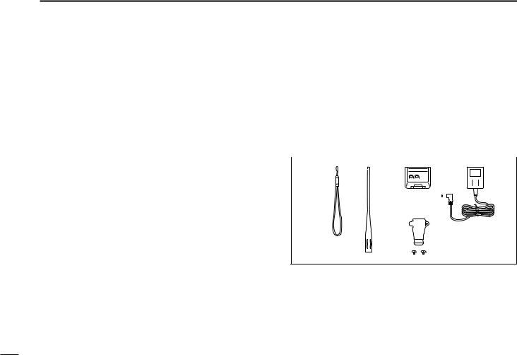
The following accessories are supplied with the transceiver. |
||||||||||||
■ [MIC/SP] jacks |
……………………………………………… 117 |
|||||||||||||
q Hand strap ………………………………………………… 1 |
||||||||||||||
■ Resetting …………………………………………………… 118 |
||||||||||||||
w Antenna |
…………………………………………………… 1 |
|||||||||||||
13 TROUBLESHOOTING ………………………………………… 119 |
||||||||||||||
e Battery pack* ……………………………………………… 1 |
||||||||||||||
14 SPECIFICATIONS |
……………………………………… 120–121 |
r Battery charger* …………………………………………… 1 |
||||||||||||
15 OPTIONS ………………………………………………… 122–124 |
t Belt clip (with screws) ………………………………… 1 set |
|||||||||||||
|
|
|
*Not supplied with some versions. |
|||||||||||
■ Optional UT-121 installation ……………………………… 123 |
|
|
|
|||||||||||
|
|
|
|
|
|
|
|
|
|
|
|
|||
■ Optional HM-75A REMOTE CONTROL MICROPHONE ……… 124 |
|
|
|
|
|
|
|
|
|
|
|
|
||
|
|
q |
w |
e |
|
|
r |
|||||||
|
|
|
|
|
|
|
|
|
|
|
|
|
|
|
|
|
|
|
|
|
|
|
|
|
|
|
|
|
|
|
|
|
|
|
|
|
|
|
|
|
|
|
|
|
|
|
|
|
|
|
|
|
|
|
|
|
|
|
|
|
|
|
|
|
|
|
|
|
|
|
|
|
|
|
|
|
|
|
|
|
|
|
|
|
|
|
|
|
|
|
|
|
|
|
|
|
|
|
|
|
|
|
|
|
|
|
|
|
|
|
|
|
|
|
|
|
|
|
|
|
|
|
|
|
|
|
|
|
|
|
|
|
|
|
|
|
|
|
|
|
|
|
|
|
|
|
|
|
|
|
|
|
|
|
|
|
|
|
|
|
|
|
|
|
|
|
|
|
|
|
|
|
|
|
|
|
|
|
|
|
|
|
|
|
|
|
|
|
|
|
|
|
|
|
t 

v
ACCESSORY ATTACHMENT 1 
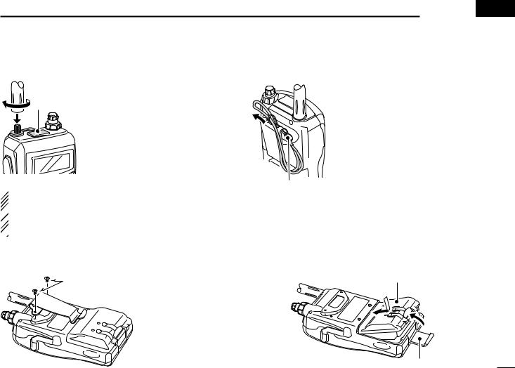
■ Antenna
Insert the supplied antenna into the antenna connector and screw down
Jack cover the antenna as shown at left.
NEVER carry the transceiver by holding the antenna.
KEEP the jack cover attached when jack is not in use to protect the connector from dust and moisture.
 For your information
Third-party antennas may increase transceiver perfor-  mance. An optional AD-92SMA ANTENNA CONNECTOR
  ADAPTER is available to connect an antenna with a BNC
  connector.
■ Belt clip
Supplied screws*
*NOTE:
USE the supplied screws only. Using screws longer than specified could
damage the transceiver.
■ Handstrap |
1 |
Slide the handstrap through the loop on the top of the belt clip as illustrated at left to facilitate carrying the transceiver.
Handstrap
■ Battery pack
Attach the Li-Ion battery pack (BP-217) or battery case (BP216) as illustrated below.
• Charge the Li-Ion battery pack before use. (pgs. 10, 11)
Battery pack/
Battery case
q
w |
Latch
1
 2 PANEL DESCRIPTION
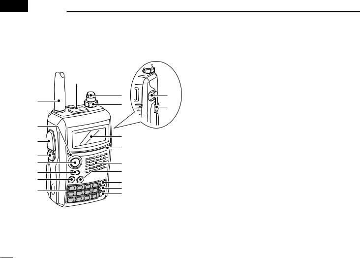
■ Front, top and side panels
|
!7 |
|
q |
!6 |
!4 |
!5 |
|
|
|
!3 |
|
|
|
w |
|
|
e |
Function display |
|
|
||
|
Internal microphone |
|
r |
|
|
t |
Speaker |
|
y |
!2 |
|
u |
!1 |
|
|
||
i |
!0 |
|
o |
||
|
qANTENNA CONNECTOR (p. 1)
Connects the supplied antenna.
•An optional AD-92SMA adapter (p. 122) is available for connecting an antenna with a BNC connector.
wTX/RX INDICATOR [TX/RX] (p. 24)
Lights green while receiving a signal or when the squelch is open; lights red while transmitting.
ePTT SWITCH [PTT] (p. 24)
Push and hold to transmit, release to receive.
rSQUELCH KEY [SQL]
Push and hold to open the squelch temporarily and monitor the operating frequency. (p. 22)
While pushing and holding this key, rotate [DIAL] to adjust the squelch level. (p. 21)
tMENU/LOCK KEY [MENU/LOCK]
Push to toggle menu screen indication ON and OFF. (p. 85)
Push and hold for 1 sec. to toggle the lock function ON and OFF. (p. 25)
yPOWER KEY [PWR]
Push and hold for 1 sec. to turn the transceiver power ON and OFF.
uMAIN/DUAL KEY [MAIN/DUAL]
Push to select the main band between A and B bands. (p. 26)
Push and hold for 1 sec. to toggle the dualwatch function ON and OFF. (p. 25)
iKEYPAD (pgs. 4, 5)
2

oCALL/RX CS KEY [CALL]/[RX CS](CALL)
Push to select the call channel/TV channel/weather channel. (p. 16)
During DV mode operation, push and hold for 1 sec. to set the received call signs (station and repeaters) for operation. (p. 47)
Enters or sends the DTMF code “C.” (pgs. 103, 104)
!0MEMORY/SELECT MEMORY WRITE KEY [MR]/[S.MW](MR)
Push to select memory mode. (p. 15)
During memory mode operation, push to toggle between memory and memory bank mode. (p. 68)
Push and hold for 1 sec. to enter select memory write mode. (p. 64)
Enters or sends the DTMF code “B.” (pgs. 103, 104)
!1VFO/MHz KEY [VFO]/[MHz](VFO)
Push to toggle select VFO mode. (p. 15)
During VFO mode operation, push and hold for 1 sec. to select and toggle 1 MHz and 10 MHz tuning steps (p. 18)
Enters or sends the DTMF code “A.” (pgs. 103, 104)
!2BAND KEY [BAND]
During VFO mode operation, push to select an operating frequency band. (pgs. 16, 17)
During memory bank mode, push to select a memory bank. (p. 68)
Enters or sends the DTMF code “D.” (pgs. 103, 104)
PANEL DESCRIPTION 2
!3EXTERNAL DC IN JACK [DC IN] |
|
Connects the supplied wall charger, BC-167, to charge |
2 |
the attached battery pack. (p. 10) |
Connect an external DC power supply through the optional CP-12L, CP-19R or OPC-254L for external DC operation. (p. 13)
!4DATA JACK [DATA]
Connects a PC through the optional data communication cable, OPC-1529R, for low-speed data communication or control the transceiver remotely using the optional RS-91 (OPC-1529R is supplied). (p. 56)
!5VOLUME CONTROL [VOL]
Rotate to adjust the audio output level. (p. 20)
!6CONTROL DIAL [DIAL]
Rotate to tune the operating frequency. (p. 18)
During memory mode, rotate to select the memory channel. (pgs. 15, 64)
While pushing and holding [BAND], selects the operating band in VFO mode. (p. 18)
While scanning, changes the scanning direction. (p. 75)
While pushing and holding [SQL], sets the squelch level. (p. 21)
While pushing and holding [BAND], selects the programmed bank in memory mode. (p. 68)
!7EXTERNAL SPEAKER/MICROPHONE JACK [MIC/SP]
Connect an optional speaker-microphone or headset, if desired.
See page 122 for a list of available options.
3

2 PANEL DESCRIPTION
D KEYPAD
KEY |
Pushed momentarily |
Pushed and held for 1 sec. |
• Inputs digit ‘1’ for frequency input, memory channel selection, • Displays the simple band scope for a single sweep. (p. 23) etc.
•While pushing [PTT], this key sends the DTMF code “1.”
•Inputs digit ‘2’ for frequency input, memory channel selection, • Starts a scan. (p. 75) etc.
•While pushing [PTT], this key sends the DTMF code “2.”
•Inputs digit ‘3’ for frequency input, memory channel selection, • Toggles the transmit output power between high and low. (p. 24)
etc. |
- “LOW” appears when low power is selected. |
• While pushing [PTT], this key sends the DTMF code “3.” |
- While pushing and holding this key, with [DIAL] rotation selects |
|
the output power. |
|
|
• Inputs digit ‘4’ for frequency input, memory channel selection, |
• Activates the following duplex functions in order. |
etc. |
- Minus duplex operation— “–DUP” appears. |
• While pushing [PTT], this key sends the DTMF code “4.” |
- Plus duplex operation— “+DUP” appears. |
|
- Simplex operation— no duplex indicator appears. |
|
- While pushing and holding this key, with [DIAL] rotation selects |
|
the duplex function. |
|
|
• Inputs digit ‘5’ for frequency input, memory channel selection, |
• Turn the frequency skip function ON and OFF in VFO mode, or |
etc. |
set the memory channel as the following skip channel in memory |
• While pushing [PTT], this key sends the DTMF code “5.” |
mode in order (p. 79). |
|
- Skip channel— “SKIP” appears. |
|
- Frequency skip channel— “PSKIP” appears. |
|
- Non-skip channel— no skip indicator appears. |
|
|
• Inputs digit ‘6’ for frequency input, memory channel selection, |
• Turn the memory name or bank name indication ON and OFF. |
etc. |
(p. 70) |
• While pushing [PTT], this key sends the DTMF code “6.” |
|
4
PANEL DESCRIPTION 2
KEY |
Pushed momentarily |
Pushed and held for 1 sec. |
|
2 |
|
• Inputs digit ‘7’ for frequency input, memory channel selection, |
• During FM/FM-N mode operation, selects repeater tone, tone |
|
|
|
etc. |
squelch, DTCS squelch and no tone operation in sequence. |
|
|
|
• While pushing [PTT], this key sends the DTMF code “7.” |
(p. 110) |
|
|
|
|
• During DV mode operation, selects digital call sign, digital code |
|
|
|
|
and no tone operation in sequence. (p. 110) |
|
|
|
|
|
|
|
|
• Inputs digit ‘8’ for frequency input, memory channel selection, |
• Selects tuning step selection. (p. 18) |
|
|
|
etc. |
|
|
|
|
• While pushing [PTT], this key sends the DTMF code “8.” |
|
|
|
|
|
|
|
|
|
• Inputs digit ‘9’ for frequency input, memory channel selection, |
• During FM/FM-N mode operation, starts tone scan function. |
|
|
|
etc. |
(p. 112) |
|
|
|
• While pushing [PTT], this key sends the DTMF code “9.” |
• During DV mode operation, selects break-in operation mode. |
|
|
|
|
(p. 51) |
|
|
|
|
|
|
|
|
• Inputs digit ‘0’ for frequency input, memory channel selection, |
• During DV mode operation, set “CQCQCQ” for station’s call sign |
|
|
|
etc. |
for operation. |
|
|
|
• While pushing [PTT], this key sends the DTMF code “0.” |
|
|
|
|
|
|
|
|
|
• Inputs MHz digit for frequency input. |
• Select DTMF memory mode. (p. 103) |
|
|
|
• While pushing [PTT], this key sends the DTMF code “F (#).” |
• During DV mode operation, to turn EMR mode operation ON, |
|
|
|
|
keep pushing and holding until 3 short and 1 long beeps are |
|
|
|
|
emitted. (p. 56) |
|
|
• During DV mode operation, selects the record track for voice • Selects the operating mode. memory. (p. 62)
• While pushing [PTT], this key sends the DTMF code “E ( ).”
5
2 PANEL DESCRIPTION
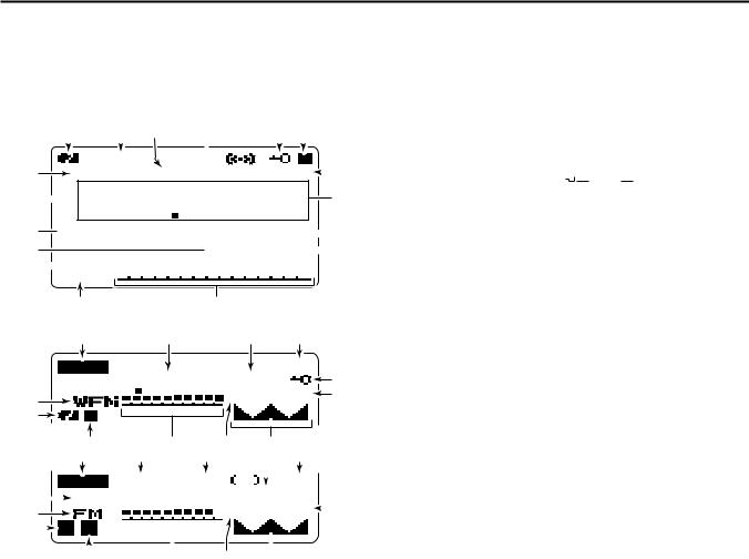
■ Function display
• Single band indication |
|
|
|
|
|
|
|
|
|
|||
q w e |
|
r |
|
t y |
||||||||
|
|
|
|
|
|
|
|
|
|
|
|
|
|
|
|
|
|
|
|
|
|
|
|||
|
|
-DUP |
|
DSQL |
|
|
|
|
|
u |
||
|
|
|
|
|
|
|
|
|||||
|
|
|
|
|
||||||||
!7 |
DV |
|
PRIO |
|
EMR |
|
||||||
|
||||||||||||
!6 B 439 70625 i
!5  MemoNamePSKIP
 o
o
!4  µ 000
µ 000 !0
!0
!3 LOWATT


!2 |
|
!1 |
|
• Dualwatch indication |
|
|
|
!6 |
i |
e |
o |
|
|
|
|
PS |
|
88 10025 PRIO |
|
t |
|||
!7 |
|
µ |
000 |
!0 |
|
|
|
|
|
|
|
q |
|
|
|
|
|
y |
!1 |
!4 |
!8 |
|
|
!6 |
w |
r |
e |
o |
|
-DUP DTCS 


|
i |
|
439 |
|
70675 PRIO |
||||||||||||||
|
|
|
|||||||||||||||||
!7 |
|
|
|
|
|
|
|
|
|
|
µ |
000 |
|
!0 |
|||||
|
|
|
|
|
|
|
|
|
|
|
|
|
|
|
|
|
|||
!3 |
|
|
|
|
|
|
|
|
|
|
|
|
|
|
|
|
|
||
|
|
|
|
|
|
|
|
|
|
|
|
|
|
|
|
|
|
|
|
|
|
|
|
|
|
|
|
|
|
|
|
|
|
|
|
|
|
|
|
|
!2 |
|
|
!1 |
!4 |
!8 |
|
|
|
||||||||||
|
|||||||||||||||||||
6 |
|
|
|
|
|
|
|
|
|
|
|
|
|
|
|
|
|
|
|
qBATTERY INDICATOR (pgs. 10, 12)
“ ” (battery indicators) appear when the Li-Ion battery pack is attached.
“ ” appears when the battery pack must be charged.
The indicators show “


 ,” “
,” “

 ” and “
 ” in sequence while charging the attached battery pack.
wDUPLEX INDICATORS (p. 29)
“+DUP” appears when plus duplex, “–DUP” appears when minus duplex is selected.
ePRIORITY WATCH INDICATOR (p. 83) Appears when priority watch is in use.
rTONE INDICATORS
• While operating in FM mode;
“TONE” appears while the subaudible tone encoder is in use. (pgs. 29, 106)
“TSQL” appears while the tone squelch function is in use. (p. 110)
“DTCS” appears while the DTCS squelch function is in use. (p. 110)
“S” appears with the “TSQL” or “DTCS” indicator
while the pocket beep function (with CTCSS or DTCS) is in use. (p. 111)
• While operating in DV mode;
“DSQL” appears while the call sign squelch function is in use. (p. 110)
“CSQL” appears while the digital code squelch function is in use. (p. 110)

“S” appears with the “DSQL” or “CSQL” indicator while the pocket beep function (with digital call sign or digital code squelch) is in use. (p. 111)
tKEY LOCK INDICATOR (pgs. 25, 113) Appears when the key lock function is activated.
yAUTO POWER OFF INDICATOR (p. 88)
Appears when the auto power OFF function is in use.
uEMR MODE INDICATOR (p. 56)
Appears when the EMR mode operation is selected.
iFREQUENCY READOUT
Displays a variety of information, such as operating frequency, set mode contents, memory names.
• The decimal point blinks during scan.
oSKIP INDICATORS (pgs. 79, 80)
“SKIP” appears when the selected memory channel is set as a skip channel.
“P SKIP” appears when the displayed frequency is set as a skip frequency.
!0MEMORY CHANNEL NUMBER INDICATOR
Shows the selected memory channel number. (pgs. 64, 65)
“C” appears when the call channel is selected. (pgs. 16, 65)
“WX” appears when the weather channel is selected. (pgs. 16, 114)
“TV” appears when the TV channel is selected. (pgs. 16, 28)
PANEL DESCRIPTION 2
!1S/RF METER |
|
Shows the relative signal strength while receiving sig- |
2 |
nals. |
Shows the output power level while transmitting. (p. 24)
!2ATTENUATOR INDICATOR (p. 22) Appears when the RF attenuator is in use.
!3LOW POWER INDICATOR (p. 24)
“LOW” appears when low power is selected.
No indicator appears when high power is selected.
!4MEMORY INDICATOR (p. 64)
Appears when memory mode is selected.
!5NAME INDICATOR (p. 70)
During memory mode operation, the programmed memory or memory bank name is displayed.
!6MAIN BAND INDICATOR (p. 14)
Shows which operating band, “A” or “B,” is selected for the main band.
!7OPERATING MODE INDICATOR (p. 21)
Shows the selected operating mode.
•DV, FM, FM-N, WFM and AM are available, depending on operating band.
!8SIMPLE BAND SCOPE INDICATOR (p. 23)
When the simple band scope function is in use, shows the band conditions.
7

 3 BATTERY CHARGING
■ Caution
Misuse of Lithium-Ion batteries may result in the following hazards: smoke, fire, or the battery may rupture. Misuse can also cause damage to the battery or degradation of battery performance.
•R DANGER! Use and charge only specified Icom battery packs with Icom radios. Only Icom battery packs are tested and approved for use with Icom radios. Using third-party or counterfeit battery packs may cause smoke, fire, or cause the battery to burst.
DBattery caution
•R DANGER! DO NOT hammer or otherwise impact the battery. Do not use the battery if it has been severely impacted or dropped, or if the battery has been subjected to heavy pressure. Battery damage may not be visible on the outside of the case. Even if the surface of the battery does not show cracks or any other damage, the cells inside the battery may rupture or catch fire.
•R DANGER! NEVER use or leave battery pack in areas with temperatures above +60˚C (+140˚F). High temperature buildup in the battery, such as could occur near fires or stoves, inside a sun heated car, or in direct sunlight may cause the battery to rupture or catch fire. Excessive temperatures may also degrade battery performance or shorten battery life.
•R DANGER! DO NOT expose the battery to rain, snow, seawater, or any other liquids. Do not charge or use a wet battery. If the battery gets wet, be sure to wipe it dry before using. The battery is not waterproof.
•R DANGER! NEVER incinerate an used battery pack since internal battery gas may cause it to rupture, or may cause an explosion.
•R DANGER! NEVER solder the battery terminals, or NEVER modify the battery pack. This may cause heat generation, and the battery may burst, emit smoke or catch fire.
•R DANGER! Use the battery only with the transceiver for which it is specified. Never use a battery with any other equipment, or for any purpose that is not specified in this instruction manual.
•R DANGER! If fluid from inside the battery gets in your eyes, blindness can result. Rinse your eyes with clean water, without rubbing them, and see a doctor immediately.
•WARNING! Immediately stop using the battery if it emits an abnormal odor, heats up, or is discolored or deformed. If any of these conditions occur, contact your Icom dealer or distributor.
•WARNING! Immediately wash, using clean water, any part of the body that comes into contact with fluid from inside the battery.
8

•WARNING! NEVER put the battery in a microwave oven, high-pressure container, or in an induction heating cooker. This could cause a fire, overheating, or cause the battery to rupture.
•CAUTION! Always use the battery within the specified temperature range, –20˚C to +60˚C (–4˚F to +140˚F). Using the battery out of its specified temperature range will reduce the battery’s performance and battery life.
•CAUTION! Shorter battery life could occur if the battery is left fully charged, completely discharged, or in an excessive temperature environment (above +50˚C; +122˚F) for an extended period of time. If the battery must be left unused for a long time, it must be detached from the radio after discharging. You may use the battery until the battery indicator shows half-capacity, then keep it safely in a cool dry place with the temperature between –20˚C to +20˚C (–4˚F to +68˚F).
BATTERY CHARGING 3
D Charging caution
• R DANGER! NEVER charge the battery pack in areas with |
3 |
extremely high temperatures, such as near fires or stoves, inside a sun heated car, or in direct sunlight. In such environments, the safety/protection circuit in the battery will activate, causing the battery to stop charging.
•WARNING! DO NOT charge or leave the battery in the battery charger beyond the specified time for charging. If the battery is not completely charged by the specified time, stop charging and remove the battery from the battery charger. Continuing to charge the battery beyond the specified time limit may cause a fire, overheating, or the battery may rupture.
•WARNING! NEVER insert the transceiver (battery attached to the transceiver) into the charger if it is wet or soiled. This could corrode the battery charger terminals or damage the charger. The charger is not waterproof.
•CAUTION! DO NOT charge the battery outside of the specified temperature range: 0˚C to +35˚C (+32˚F to +95˚F). Icom recommends charging the battery at +20˚C (+68˚F). The battery may heat up or rupture if charged out of the specified temperature range. Additionally, battery performance or battery life may be reduced.
9

3 BATTERY CHARGING
■ Regular charging
Prior to using the transceiver for the first time, the battery pack must be fully charged for optimum life and operation.
D Battery indicators
The indicators show “


 ,” “
,” “

 ” and “
 ” in sequence while charging, and both indicators disappear when completely charged.
DCharging note
•Be sure to turn the transceiver power OFF.
Otherwise the battery pack will not be charged completely or takes longer charging time periods.
•External DC power operation becomes possible when using an optional CP-12L, CP-19R or OPC-254L. The attached battery pack is also charged simultaneously, except during transmit. (see p. 11 for more details)
•The external DC power supply voltage must be within 10–16 V to charge the battery pack and operation when using an optional OPC-254L.
• BC-167A/D
to AC outlet
Transceiver
• CP-12L (Optional)
to
[DC IN]
to cigarette lighter socket (12 V DC)
• CP-19R (Optional)
Turn power OFF while charging the battery pack.
• Charging time period: • OPC-254L (Optional)
Approx. 6 hours
to 12 V DC (power supply)
Black: _
White: +
10

■ Rapid charging
The optional BC-139 provides rapid charging of the battery pack.
• Charging period: 2.5 hours (with BP-217)
DCharging note
•Be sure to turn the transceiver power OFF.
Detach the battery pack from the transceiver then charge the battery pack by itself, or charge the battery with regular charging when the transceiver power cannot be turned OFF. Otherwise the battery pack will not be charged (charging indicator on the BC-139 blinks orange).
•The desktop charger, BC-139, can only be charged BP-217. Other types of rechargeable battery, Ni-Cd or Ni-MH, cannot be charged.
•If the charging indicator blinks orange, there may be a problem with the battery pack (or charger). Reinsert the battery pack or contact your dealer.
•The optional CP-12L, CP-19R and OPC-254L can be used instead of the supplied AC adapter (BC-123). Connect one of these to the [AC ADAPTER] jack in this case.
BATTERY CHARGING 3
Transceiver |
|
|
(with battery pack) |
|
3 |
|
|
|
Turn power OFF. |
Battery pack |
|
|
|
|
to AC outlet |
|
Check the |
|
|
|
|
|
orientation. |
A |
|
Adapter (supplied |
|
|
|
|
|
with BC-139) |
BC-123 |
|
Charging |
(supplied |
|
terminal |
|
|
|
with BC-139) |
|
|
to [AC ADAPTER] |
|
BC-139 (optional) |
Charging indicator |
Desktop charger |
|
|
||
Charging : Orange |
|
|
Finished |
: Green |
|
11
3 BATTERY CHARGING
■ Optional battery case
Install 2 R6 (AA) size alkaline batteries into the optional BP-216 BATTERY
CASE.
• Be sure to observe the correct polarity.
 A built-in step-up convertor in the BP-216 increases the
voltage to 5 V DC.
 Approx. 100 mW of output power is possible with the BP-
  216 operation. Also, no transmit output power selection is
  available.
 Keep battery contacts clean. It’s a good idea to clean bat-
  tery terminals once a week.
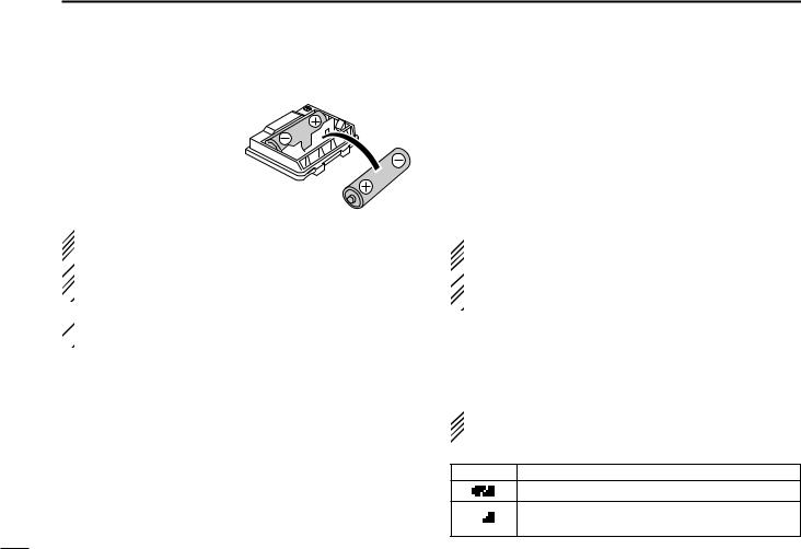
D Battery information
The batteries may seem to have low capacity when used in low temperatures such as –10°C (+14°F) or below. Keep the battery case or pack warm in this case.
D Battery replacement
When the batteries become exhausted, the function display may blink or have a lower contrast. In these cases, replace all batteries with new, same brand, alkaline batteries.
■ Battery information
D Battery life
The transceiver operates with the BP-217 as follows. However, when operating in DV mode, operating time may be shortened by one-half hour.
•VHF band : Approx. 5 hours
•UHF band : Approx. 4.5 hours
(Tx: Rx: Stand-by=1: 1: 8)
 Even when the transceiver power is OFF, a slight current
still flows in the circuits. Remove the battery pack or case
 from the transceiver when not using it for a long time. Oth-
  erwise, the battery pack or installed batteries will become
  exhausted.
D Battery indicator
The battery indicator, “  ,” appears only when the BP-217 is attached to the transceiver.
 The battery indicator does not appear when turning power
ON after the charging is completed without disconnecting  the battery charger or external DC power.
Indication |
Battery condition |
The battery has ample capacity.
The battery is nearing exhaustion. Charging is necessary.
12
BATTERY CHARGING 3
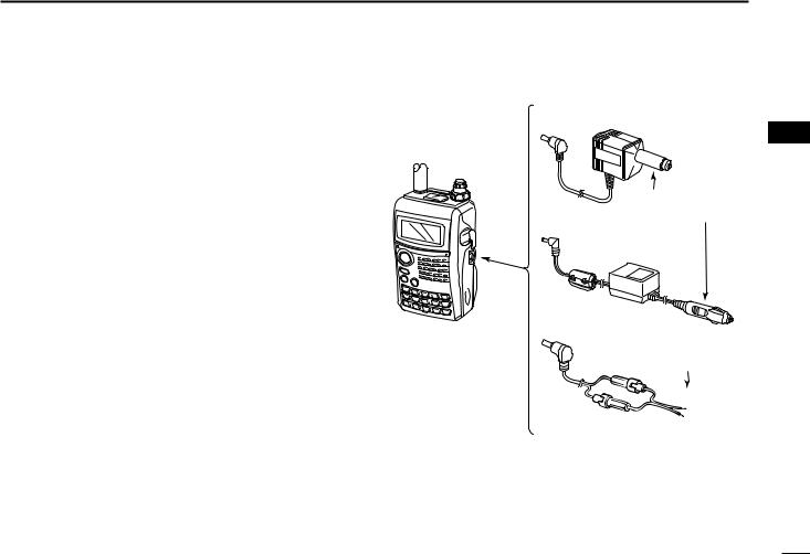
■ External DC power operation
An optional cigarette lighter cable (CP-12L or CP-19R; for 12 V cigarette lighter socket) or external DC power cable (OPC-254L)
can be used for external power operation.
Transceiver
D Operating note
• Power supply range is between 10.0–16.0 V DC.
NEVER CONNECT OVER 16 V DC directly into the [DC IN] jack of the transceiver.
•BE SURE to use CP-12L,CP-19R or OPC-254L when connecting a regulated 12 V DC power supply.
Use an external DC-DC converter to connect the transceiver through optional CP-12L, CP-19R or OPC-254L to a 24 V DC power source.
•The voltage of the external power supply must be within 10–16 V DC when using either CP-12L, CP-19R or OPC254L, otherwise, use the battery pack.
•Up to 5 W (approx.) of maximum output power is provided with the external DC power operation, however, when the supplied voltage exceeds 14 V, the built-in protection circuit activates to reduce the transmit output power to 0.5 W (approx.).
•Disconnect the power cables from the transceiver when not using it. Otherwise, the vehicle battery will become exhausted.
•The power save function is deactivated automatically during external DC power operation.
to
[DC IN]
• CP-12L (Optional)
3
to cigarette lighter socket (12 V DC)
• CP-19R (Optional)
• OPC-254L (Optional)
to 12 V DC (power supply)
Black: _
White: +
13
 4 FREQUENCY AND CHANNEL SETTING
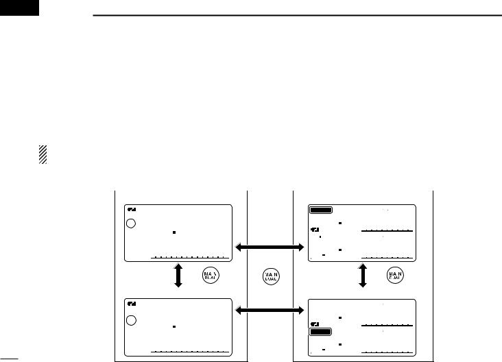
■ Main band selection
The IC-91A/91AD has two independent operating bands; A band (VFO A) and B band (VFO B). A band (VFO A) can operate 0.495 MHz to 999.990 MHz*, and B band (VFO B) can operate 118 MHz to 174 MHz and 350 MHz to 470 MHz.
*Some frequency ranges are blocked for the USA version by regulation.
DHow to change the main band
Push [MAIN/DUAL] to toggle between A and B band.
Push and hold [MAIN/DUAL] for 1 sec. to turn the dualwatch operation ON and OFF.
•While in dualwatch operation, the display indicates A band in the upper half and B band in the lower half.
NOTE: When in dualwatch mode, transmission is available |
During dualwatch operation, push [MAIN/DUAL] to select |
||||||||
from the MAIN band only. |
|
|
A band or B band as the main operating band alternately. |
||||||
Single band operation |
|
Dualwatch operation |
|
|
|
||||
|
|
|
|
|
|
||||
|
• Selecting A band |
|
• Selecting upper side as main band |
||||||
|
+DUP DTCS |
|
+DUP DTCS |
W PS |
|||||
|
FM |
PRIO WX EMR |
146 010 |
25 PRIO |
|||||
|
A 146 01025 |
|
µ |
000 |
|
||||
|
|
FM |
|
|
|
|
|||
MemoNameP SKIP |
+DUP DTCS |
W PS |
||
µ |
000 |
440 000 |
50 PRIO EM |
|
µ |
000 |
|||
LOW |
|
|
|
|
ATT |
|
FM |
|
|
|
|
Push |
|
|
Push |
|
|
Push |
|
|
|
|
|
|
|
|||
|
|
|
|
|||
• Selecting B band |
for 1 sec. • Selecting lower side as main band |
|||||
+DUP DTCS |
|
+DUP DTCS |
W PS |
|||
FM PRIO WX EMR |
146 010 |
25 PRIO |
||||
B 440 00025 |
µ |
000 |
||||
|
FM |
|
|
|
||
MemoNameP SKIP |
+DUP DTCS |
W PS |
||
µ |
000 |
440 000 |
50 PRIO EM |
|
µ |
000 |
|||
LOW |
|
|
|
|
ATT |
|
FM |
|
|
14
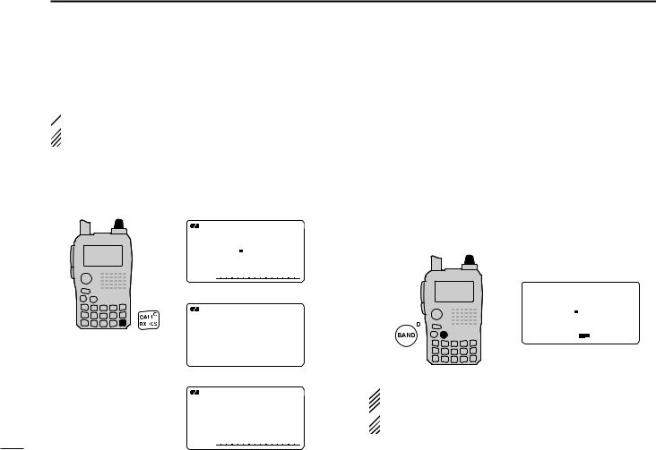
■ Mode selection
D VFO mode
VFO mode is used to set the desired frequency.
Push [VFO] to select VFO mode.
•VFO mode indication
 +DUP DTCS


FM PRIO WX EMR
A 146 01025
MemoNameP SKIP
µ 000
LOW
ATT 
What is VFO?
VFO is an abbreviation of Variable Frequency Oscillator. Frequencies for both transmitting and receiving are generated and controlled by the VFO.
FREQUENCY AND CHANNEL SETTING 4
D Memory mode
Memory mode is used for operation on memory channels |
|
which store programmed frequencies. |
4 |
|
qPush [MR] to select memory mode.
•“µ ” appears when memory mode is selected.
•Memory mode indication
 +DUP DTCS


FM PRIO WX EMR
A 146 01025
MemoNameP SKIP
µ 000
LOW
ATT 


Appear
wRotate [DIAL] to select the desired memory channel.
•Only programmed memory channels can be selected.
•Enter the memory channel directly to select the desired memory channel. (p. 64)
•See p. 66 for memory programming details.
15
4 FREQUENCY AND CHANNEL SETTING
D Call/TV*/Weather† channels
Call channels are used for quick recall of most-often used frequencies.
 *Appears only when TV channels are programmed via the
  optional RS-91. Also available for A band operation only.
†Available for the USA version only.
qPush [CALL] several times to select call channels/TV channels (A band only)/Weather channels.
• Call/TV/Weather channels can be selected in sequence.
wRotate [DIAL] to select the desired channel.
• Call channel indication
[DIAL] |
+DUP DTCS |
|
|
FM |
PRIO WX EMR |
A 146 01025
MemoNameP SKIP
µ C0
LOW
ATT 


• TV channel indication
+DUP DTCS


WFM |
PRIO WX EMR |
|
A |
10 ch 25 |
|
MemoNameP SKIP |
||
|
µ |
TV |
LOW
ATT 
• Weather channel indication
+DUP DTCS |
|
|
WFM |
PRIO WX EMR |
|
A |
1 |
25 |
|
|
|
MemoNameP SKIP
µ WX
LOW
ATT 


■ Operating band selection
The transceiver can receive the AM broadcast, HF bands, 50 MHz, FM broadcast, VHF air, 144 MHz, 300 MHz, 400 MHz or 800 MHz* bands. (Some bands are not selectable for B band operation. See next page for details.)
In VFO mode, push [BAND] several times to select the desired frequency band.
•If the other than VFO mode is selected, such as a memory channel/call channel/TV channel/Weather channel, push [VFO] to select VFO mode first, then push [BAND] to select the desired band.
While pushing and holding [BAND], rotating [DIAL] also selects frequency band.
[DIAL]
 +DUP DTCS


FM PRIO WX EMR
A 146 01025
MemoNameP SKIP
µ 000
LOW
ATT 
 Available frequency bands are different depending on ver-
sion. See the specification for details. (pgs. 120, 121)
 *Some frequency ranges are blocked for the USA version by regulation.
16

|
|
FREQUENCY AND CHANNEL SETTING |
4 |
|
• Available frequency bands |
|
|
|
1 |
|
|
|
|
|
• A band |
|
|
|
2 |
+DUP DTCS |
+DUP DTCS |
+DUP DTCS |
+DUP DTCS |
3 |
AM PRIO WX EMR |
AM PRIO WX EMR |
FM PRIO WX EMR |
WFM PRIO WX EMR |
|
A 001 62025 |
A 005 00025 |
A 051 00025 |
A 076 00025 |
|
MemoNameP SKIP |
|
MemoNameP SKIP |
|
MemoNameP SKIP |
MemoNameP SKIP |
4 |
||||||||||
AM broadcast band |
|
HF band |
|
|
|
50 MHz band |
|
FM broadcast band |
|
5 |
||||||
|
|
|
|
|
|
|
|
|
|
|
|
|
|
|
|
6 |
+DUP DTCS |
|
|
|
|
|
|
|
+DUP DTCS |
|
+DUP DTCS |
|
7 |
||||
FM |
PRIO WX EMR |
|
|
|
|
|
|
FM |
PRIO WX EMR |
AM |
PRIO WX EMR |
|||||
A 850 00025 |
|
|
|
|
|
|
A 146 01025 |
A 118 00025 |
8 |
|||||||
MemoNameP SKIP |
|
|
|
|
|
|
MemoNameP SKIP |
MemoNameP SKIP |
||||||||
800 MHz band |
|
|
|
|
|
|
|
|
|
144 MHz band |
|
VHF air band |
|
9 |
||
|
|
|
|
|
|
|
|
|
|
|
10 |
|||||
|
|
+DUP DTCS |
|
|
|
+DUP DTCS |
|
|
|
|
|
|
|
|||
|
|
|
|
|
|
|
|
|
|
|
|
|
||||
|
FM |
PRIO WX EMR |
AM |
PRIO WX EMR |
|
|
|
|
|
11 |
||||||
|
A |
440 000 |
25 |
A |
370 000 |
25 |
: Push |
|
|
|
||||||
|
|
|
|
|
|
|
|
12 |
||||||||
|
MemoNameP SKIP |
MemoNameP SKIP |
Rotating [DIAL] while pushing |
|
||||||||||||
|
|
|
|
|
|
|
|
|
|
|
|
|||||
|
400 MHz band |
|
|
300 MHz band |
|
|
Initial frequencies shown differ according to version. |
13 |
||||||||
• B band |
|
|
|
|
|
|
|
|
|
|
|
|
|
|
|
14 |
|
|
|
|
|
|
|
|
|
|
|
|
|
|
|
15 |
|
+DUP DTCS |
|
|
+DUP DTCS |
|
|
+DUP DTCS |
|
+DUP DTCS |
|
|||||||
AM |
PRIO WX EMR |
|
FM |
PRIO WX EMR |
|
FM |
PRIO WX EMR |
FM |
PRIO WX EMR |
|||||||
A |
|
|
25 |
|
A |
|
|
25 |
|
A |
|
25 |
A |
|
25 |
16 |
B 118 000 |
|
|
B 146 010 |
|
|
B 370 000 |
|
B 440 000 |
|
|||||||
MemoNameP SKIP |
|
MemoNameP SKIP |
|
MemoNameP SKIP |
MemoNameP SKIP |
17 |
||||||||||
VHF air band |
|
|
144 MHz band |
|
|
300 MHz band |
|
400 MHz band |
|
|||||||
|
|
|
|
|
|
18 |
||||||||||
|
|
|
|
|
|
|
|
|
|
|
|
|
|
|
|
|
|
|
|
|
|
|
|
|
|
|
|
|
|
|
|
|
19 |
17

4 FREQUENCY AND CHANNEL SETTING
■ Setting a tuning step
The tuning step can be selected for each frequency band. The following tuning steps are available for the IC-91A/91AD.
• 5.0 kHz* |
• 6.25 kHz* |
• 8.33 kHz† |
• 9.0 kHz‡ |
• 10.0 kHz |
• 12.5 kHz |
• 15.0 kHz |
• 20.0 kHz |
• 25.0 kHz |
• 30.0 kHz |
• 50.0 kHz |
• 100.0 kHz • 125.0 kHz • 200.0 kHz |
|
||
* Appears for below the 600 MHz bands only.
† Appears for the VHF air band only.
‡ Appears for the AM broadcast band only.
D Tuning step selection
qPush [VFO] to select VFO mode, if necessary.
wPush [BAND] to select the desired frequency band.
•Or, while pushing and holding [BAND], rotate [DIAL] to select the desired frequency band.
ePush and hold [TS](8) for 1 sec. to enter tuning step set mode. rRotate [DIAL] to select the desired tuning step.
tPush [TS](8) (or [VFO]) to return to VFO mode.
[DIAL]
 +DUP DTCS


FM PRIO WX EMR
A 146 01025
P SKIP


 µ 000
µ 000
SET-TS:5.0kHz
5 kHz tuning step
■ Setting a frequency
D Using the dial
qPush [VFO] to select VFO mode, if necessary.
wSelect the desired frequency band with [BAND].
•Or, while pushing and holding [BAND], rotate [DIAL] to select the desired frequency band.
eRotate [DIAL] to select the desired frequency.
•The frequency changes according to the preset tuning steps.
See the left-hand side of the page to set the tuning step.
•Push and hold [MHz](VFO) for 1 sec. then rotate [DIAL] to change the frequency in 1 MHz steps, or push and hold for 1 sec. again then rotate [DIAL] to change the frequency in 10 MHz steps. (Each pushing and holding for 1 sec. toggles 1 MHz or 10 MHz tuning steps. Push [MHz](VFO) to cancel it.)
|
+DUP DTCS |
|
|||
[DIAL] |
FM |
PRIO WX EMR |
|||
A 146 01025 |
|||||
|
|||||
|
[DIAL] changes the fre- |
||||
|
quency according to the se- |
||||
|
lected tuning step. |
|
|||
|
+DUP DTCS |
|
|||
|
FM |
PRIO WX EMR |
|||
|
A 146 01025 |
||||
|
After |
pushing |
and |
holding |
|
|
[MHz](VFO) |
for |
1 sec., |
||
|
[DIAL] changes the frequen- |
||||
|
cy in 1 MHz/10 MHz steps. |
||||
18

D Using the keypad
The frequency can be directly set via numeric keys.
•If a frequency outside the frequency range is entered, the previously displayed frequency is automatically recalled after editing last digit.
qPush [VFO] to select VFO mode, if necessary.
wEnter the desired frequency via the keypad.
Depending on the tuning step setting, the 1 kHz digit may not acceptable as input. In this case, enter “0” as 1 kHz digit, then rotate [DIAL] to set the desired frequency.
FREQUENCY AND CHANNEL SETTING 4
• Entering 146.520 MHz
 +DUP DTCS
FM PRIO WX
A 146 52025
 +DUP DTCS
FM PRIO WX
A 146 52025
 +DUP DTCS
FM PRIO WX
A 146 52025
 +DUP DTCS
FM PRIO WX
A 146 52025
 +DUP DTCS
FM PRIO WX
A 146 52025
 +DUP DTCS
FM PRIO WX
A 146 52025
• Editting to 684 kHz
• Entering 79.3 MHz
 +DUP DTCS FM PRIO WX

 A 730 00025
 +DUP DTCS FM PRIO WX


 A 790 00025
 +DUP DTCS FM PRIO WX


 A 079 30025
 +DUP DTCS FM PRIO WX
A 079 30025
 +DUP DTCS FM PRIO WX
A 079 30025
 +DUP DTCS FM PRIO WX
A 079 30025
•Changing 100 kHz and below.
Editting 146.520 MHz to 146.240 MHz
 +DUP DTCS FM PRIO WX


 A 146 24025
 +DUP DTCS
FM PRIO WX
A 146 24025
 +DUP DTCS
FM PRIO WX
A 146 24025
 +DUP DTCS
FM PRIO WX
A 146 24025
 +DUP DTCS FM PRIO WX
A 000 68425
1
2
3
4
5
6
7
8
9
10
11
12
13
14
15
16
17
18
19
19

 5 BASIC OPERATION
■ Receiving
Make sure charged battery pack (BP-217) or brand new alkaline batteries (BP-216) are installed (pgs. 1, 12).
qPush and hold [PWR] for 1 sec. to turn power ON.
wRotate [VOL] to set the desired audio level.
•The frequency display shows the volume level while setting. See the section at right for details.
eSet the receiving frequency. (p. 18)
rSet the squelch level. (p. 21)
•While pushing and holding [SQL], rotate [DIAL].
•The first click of [DIAL] indicates the current squelch level.
•“LEVEL 1” is loose squelch (for weak signals) and “LEVEL 9” is tight squelch (for strong signals).
•“AUTO” indicates automatic level adjustment by a noise pulse counting system.
•Push and hold [SQL] to open the squelch manually.
tWhen a signal is received:
•Squelch opens and audio is output.
•The S/RF-meter shows the relative signal strength level.
|
e Set frequency |
|
r Set squelch level |
r Push for setting |
w Set audio level |
the squelch |
|
(Push to monitor) |
|
q [PWR] |
e Select band |
|
■ Setting audio volume
Rotate [VOL] to adjust the audio level.
•If squelch is closed, push and hold [SQL] to verify the audio level.
•The display shows the volume level while setting.
 +DUP DTCS


FM PRIO WX EMR
 [VOL] A 146 01025
MemoNameP SKIP
µ 000
LOW
ATT 


P SKIP
µ 000
VOL
Volume level indicator
P SKIP
µ 000
VOL
Minimum setting (no audio)
P SKIP
µ 000
VOL
Maximum setting
20
■ Setting squelch level
The squelch circuit mutes the received audio signal depending on the signal strength. The receiver has 9 squelch levels, a continuously open setting and an automatic squelch setting.
While pushing and holding [SQL], rotate [DIAL] to select the squelch level.
•“LEVEL 1” is loose squelch (for weak signals) and “LEVEL 9” is tight squelch (for strong signals).
•“AUTO” indicates automatic level adjustment by a noise pulse counting system.
•“OPEN” indicates continuously open setting.
[DIAL] |
+DUP DTCS |
|
FM |
PRIO WX EMR |
|
A 146 01025
MemoNameP SKIP
µ 000
LOW
ATT 


P SKIP
µ 000
SQUELCH:AUTO
Automatic squelch
P SKIP
µ 000
SQUELCH:LEVEL9
Maximum level
BASIC OPERATION 5
■ Operating mode selection
Operating modes are determined by the modulation of the radio signals. The transceiver has total 5 operating modes (A band: FM, WFM and AM modes, B band FM, FM-N, AM and DV modes). The mode selection is stored independently for each band and memory channel.
Typically, AM mode is used for the AM broadcast stations (0.495–1.620 MHz) and air band (118–136.995 MHz), and WFM is used for FM broadcast stations (76–107.9 MHz).
WFM mode cannot be selected above 810 MHz for USA version.
Push and hold [MODE](REC) for 1 sec. several times to select the desired operating mode.
•Display example
 FM
FM
A 146 01025
FM mode
 WFM
WFM
A 176 00025
WFM mode
 AM
AM
A 118 00025
AM mode
1
2
3
4
5
6
7
8
9
10
11
12
13
14
15
16
17
18
19
21

5 BASIC OPERATION
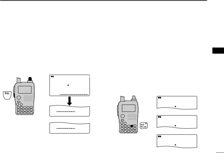
■ Monitor function
This function is used to listen to weak signals without disturbing the squelch setting or to open the squelch manually even when mute functions such as the tone squelch are in use.
Push and hold [SQL] to monitor the operating frequency.
•The 1st segment of the S-meter blinks.
 +DUP DTCS


FM PRIO WX EMR
A 146 01025
MemoNameP SKIP
µ 000
LOW
ATT 
The 1st segment blinks
 The [SQL] key can be set to ‘sticky’ operation in set mode.
  See page 89 for details.
■ Attenuator function
The attenuator prevents a desired signal from distortion by very strong signals near the desired frequency or when very strong electric fields, such as from a broadcasting station, are near your location. The attenuation is about 10 dB.
q Enter “ATTENUATOR” in set mode. (p. 88)
MENU screen SET MODE ATTENUATOR
(Push [MENU/LOCK]) (Rotate [DIAL]†, then push [ï](5)†.)
w Rotate [DIAL]† to select “ON” or “OFF.”
ePush [ï](5) (or [Ω](4)) to return to set mode, and push [MENU/LOCK] to return to frequency indication.
• “ATT” appears on the function display when “ON” is selected.
[DIAL]
 +DUP DTCS


FM PRIO WX EMR
A 146 01025
MemoNameP SKIP
µ 000
LOW
ATT 
Appears.
†[DIAL] [∫](2)/[√](8) |
[ï](5) [≈](6) |
22
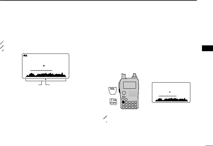
■ Band scope
The band scope function allows you to visually check a specified frequency range around the center frequency.
 About the sweep steps: The specified tuning step in each
  frequency band (in VFO mode) or programmed tuning step
  (in memory mode) is used during sweep.
|
+DUP DTCS |
FM PRIO WX EMR |
|
A |
145 78025 |
B |
|
P SKIP


 µ 000
µ 000
Band scope indication |
Sweep marker |
D Single sweep
q Set the desired frequency as band scope center frequency.
wPush and hold [SCOPE](1) for 1 sec. to start a single sweep.
•1 short and 1 long beeps sound.
•Signal conditions (strengths) appear starting from the center of the range.
eRotate [DIAL] to set the highlighted cursor to the desired signal and set the frequency of the signal.
r Push [VFO] to return to normal operation.
BASIC OPERATION 5
D Continuous sweep
q Set the desired frequency as band scope center frequency.
wPush and hold [SCOPE](1) for 3 sec. to start continuous sweep.
•2 short beeps sound after 1 short and 1 long beeps.
•Signal conditions (strengths) appear starting from the center of the range.
ePush and hold [SCOPE](1) for 1 sec. to cancel sweep.
• Pushing [SQL] also cancels sweep.
r Push [VFO] to return to normal operation.
 +DUP DTCS


FM PRIO WX EMR
A 145 78025
B
P SKIP


 µ 000
µ 000
 The receive audio during sweeping can be muted in
  sounds set mode. See page 102 for details.
1
2
3
4
5
6
7
8
9
10
11
12
13
14
15
16
17
18
19
23
5 BASIC OPERATION
■ Transmitting
CAUTION: Transmitting without an antenna will damage the transceiver.
 NOTE: To prevent interference, listen on the channel before transmitting by pushing and holding [SQL].
qSet the operating frequency. (pgs. 18, 19)
•Transmission is available on the 144 MHz/440 MHz amateur bands only.
•Select output power if desired. See the section at right for details. wPush and hold [PTT] to transmit.
•Tx/Rx indicator lights red.
•S/RF meter shows the output power level.
eSpeak into the microphone using your normal voice level.
•DO NOT hold the transceiver too close to your mouth or speak too loudly. This may distort your speech.
rRelease [PTT] to return to receive.

 Microphone
Tx/Rx indicator
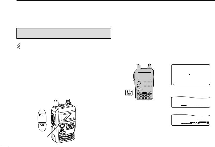
■ Transmit power selection
The transceiver has two output power levels to suit your operating requirements. Low output power during short-range communications may reduce the possibility of interference to other stations and will reduce current consumption.
Push and hold [LOW](3) for 1 sec. to toggle the transmit output power between High and Low.
• “LOW” appears when the low power is selected.
 +DUP DTCS


FM PRIO WX EMR
A 146 01025
MemoNameP SKIP
µ 000
LOW
ATT 
Appears
LOW
Low power transmission
LOW
High power transmission
24
 Loading...