


INSTRUCTION MANUAL
HF/50 MHz
ALL MODE TRANSCEIVER
This device complies with Part 15 of the FCC rules. Operation is subject to the following two conditions: (1) This device may not cause harmful interference, and (2) this device must accept any interference received, including interference that may cause undesired operation.
IMPORTANT
READ THIS INSTRUCTION MANUAL CAREFULLY before attempting to operate the
transceiver.
SAVE THIS INSTRUCTION MANUAL. This manual contains important safety and operating instructions for the IC-756PROIII.
EXPLICIT DEFINITIONS
WORD |
DEFINITION |
|
|
Personal injury, fire hazard or electric RWARNING shock may occur.
CAUTION Equipment damage may occur.
If disregarded, inconvenience only. No NOTE risk or personal injury, fire or electric
shock.
FOREWORD |
|
SUPPLIED ACCESSORIES |
We understand that you have a choice of many different radios in the market place. We would like to take a couple of moments of your time to thank you for making your IC-756PROIII your radio of choice, and hope you agree with Icom’s philosophy of “technology first.” Many hours of research and development went into the design of your IC-756PROIII.
D FEATURES
+30 dBm class IP3 (at 14 MHz band) and further improved 3rd order IMD characteristics
Real time spectrum scope with mini-scope function
Boudot RTTY demodulator and RTTY transmit message memory
Selectable SSB transmission passband width (Each for Higher and lower pass frequency)
Digital IF filter allows you to select 51 types of filter shapes while receiving a station
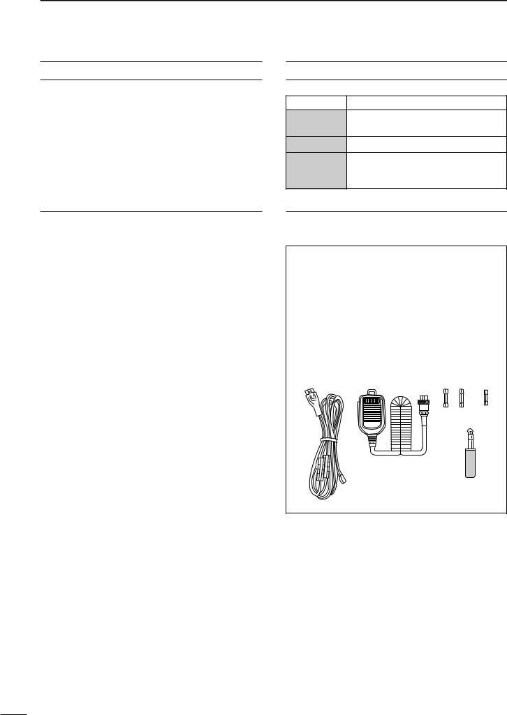
The transceiver comes with the following accessories.
|
|
|
Qty. |
q DC power cable (OPC-025D) |
.......................... |
1 |
|
w Hand microphone (HM-36) .............................. |
|
1 |
|
e Spare fuses (FGB 30 A) .................................. |
|
2 |
|
r Spare fuse (FGB 5 A) ...................................... |
|
1 |
|
t CW keyer plug (AP-330) .................................. |
|
1 |
|
q |
w |
e |
r |
t
Spurious may be received near the following frequencies. These are made in the internal circuit and does not indicate a transceiver malfunction:
6.144 MHz, 8.000 MHz,
12.288 MHz, 12.890 MHz (when spectrum scope is ON),
18.433 MHz, 24.573 MHz, 52 MHz
i
Icom, Icom Inc. and the 
 are registered trademarks of Icom Incorporated (Japan) in the United States, the United Kingdom, Germany, France, Spain, Russia and/or other countries.

PRECAUTIONS
R WARNING RF EXPOSURE! This device emits Radio Frequency (RF) energy. Extreme caution should be observed when operating this device. If you have any questions regarding RF exposure and safety standards please refer to the Federal Communications Commission Office of Engineering and Technology’s report on Evaluating Compliance with FCC Guidelines for Human Radio Frequency Electromagnetic Fields (OET Bulletin 65).
R WARNING HIGH VOLTAGE! NEVER attach an antenna or internal antenna connector during transmission. This may result in an electrical shock or burn.
RWARNING! NEVER operate the transceiver with a headset or other audio accessories at high volume levels. Hearing experts advise against continuous high volume operation. If you experience a ringing in your ears, reduce the volume or discontinue use.
RCAUTION! NEVER change the internal settings of the transceiver. This result in reduced transceiver performance and/or damage to the transceiver.
In particular, incorrect settings for transmitter circuits, such as output power, idling current, etc., might damage the expensive final devices.
The transceiver warranty does not cover any problems caused by unauthorized internal adjustment.
R NEVER apply AC to the [DC13.8V] jack on the transceiver rear panel. This could cause a fire or ruin the transceiver.
RNEVER apply more than 16 V DC, such as a 24 V battery, to the [DC13.8V] jack on the transceiver rear panel. This could cause a fire or ruin the transceiver.
RNEVER let metal, wire or other objects touch any internal part or connectors on the rear panel of the transceiver. This may result in an electric shock.
R NEVER expose the transceiver to rain, snow or any liquids.
RNEVER installing the transceiver in a place without adequate ventilation. Heat dissipation may be affected, and the transceiver may be damaged.
RNEVER operate or touch the transceiver with wet hands. This may result in an electric shock or damage to the transceiver.
AVOID using or placing the transceiver in areas with temperatures below –10°C (+14°F) or above +50°C (+122°F). Be aware that temperatures on a vehicle’s dashboard can exceed 80°C (+176°F), resulting in permanent damage to the transceiver if left there for extended periods.
AVOID placing the transceiver in excessively dusty environments or in direct sunlight.
AVOID placing the transceiver against walls or putting anything on top of the transceiver. This will obstruct heat dissipation.
Place unit in a secure place to avoid inadvertent use by children.
During mobile operation, DO NOT operate the transceiver without running the vehicle’s engine. When transceiver power is ON and your vehicle’s engine is OFF, the vehicle’s battery will soon become exhausted.
Make sure the transceiver power is OFF before starting the vehicle. This will avoid possible damage to the transceiver by ignition voltage spikes.
During maritime mobile operation, keep the transceiver and microphone as far away as possible from the magnetic navigation compass to prevent erroneous indications.
BE CAREFUL! The heatsink will become hot when operating the transceiver continuously for long periods.
BE CAREFUL! If a linear amplifier is connected, set the transceiver’s RF output power to less than the linear amplifier’s maximum input level, otherwise, the linear amplifier will be damaged.
The LCD display may have cosmetic imperfections that appear as small or dark spots. This is not a malfunction or defect, but a normal characteristic of LCD displays.
Use Icom microphones only (supplied or optional). Other manufacturer’s microphones have different pin assignments, and connection to the IC-756PROIII may damage the transceiver.
For U.S.A. only
CAUTION: Changes or modifications to this device, not expressly approved by Icom Inc., could void your authority to operate this device under FCC regulations.
ii

TABLE OF CONTENTS
IMPORTANT .................................................................. |
i |
|
FOREWORD ................................................................. |
i |
|
EXPLICIT DEFINITIONS ............................................... |
i |
|
SUPPLIED ACCESSORIES .......................................... |
i |
|
PRECAUTIONS ............................................................ |
ii |
|
TABLE OF CONTENTS .............................................. |
iii |
|
1 |
PANEL DESCRIPTION ..................................... |
1–12 |
|
■ Front panel ....................................................... |
1 |
|
■ LCD display ..................................................... |
9 |
|
■ Screen menu arrangement ............................ |
10 |
|
■ Rear panel ...................................................... |
11 |
|
■ Microphone (HM-36) ...................................... |
12 |
2 |
INSTALLATION AND CONNECTIONS .......... |
13–20 |
|
■ Unpacking ...................................................... |
13 |
|
■ Selecting a location ........................................ |
13 |
|
■ Grounding ...................................................... |
13 |
|
■ Antenna connection ....................................... |
13 |
|
■ Required connections .................................... |
14 |
|
■ Advanced connections ................................... |
15 |
|
■ Power supply connections ............................. |
16 |
|
■ Linear amplifier connections .......................... |
17 |
|
■ External antenna tuner |
|
|
connections .................................................... |
18 |
|
■ Transverter jack information .......................... |
18 |
|
■ Microphone connector information ................ |
18 |
|
■ FSK and AFSK (SSTV) |
|
|
connections .................................................... |
19 |
|
■ Accessory connector information ................... |
20 |
3 |
BASIC OPERATION ....................................... |
21–32 |
|
■ When first applying power |
|
|
(CPU resetting) .............................................. |
21 |
|
■ Initial settings ................................................. |
21 |
|
■ VFO description ............................................. |
22 |
|
■ Selecting VFO/memory mode ........................ |
23 |
|
■ Main/Sub band selection ............................... |
23 |
|
■ Selecting an operating band .......................... |
24 |
|
DUsing the band stacking registers ............... |
24 |
|
■ Frequency setting .......................................... |
25 |
|
DTuning with the tuning dial ........................... |
25 |
|
DDirect frequency entry with the keypad ....... |
25 |
|
DQuick tuning step......................................... |
26 |
|
DSelecting “kHz” step .................................... |
26 |
|
DSelecting 1 Hz step...................................... |
27 |
|
D1⁄4 tuning function |
|
|
(SSB data/CW/RTTY only) .......................... |
27 |
|
DAuto tuning step function ............................. |
28 |
|
DBand edge warning beep............................. |
28 |
|
■ Operating mode selection .............................. |
29 |
|
■ Volume setting ............................................... |
29 |
|
■ Squelch and receive (RF) sensitivity ............. |
30 |
|
■ Meter function ................................................ |
31 |
|
■ SWR reading ................................................. |
31 |
|
■ Basic transmit operation ................................ |
32 |
|
DTransmitting ................................................. |
32 |
|
DMicrophone gain adjustment ....................... |
32 |
4 |
RECEIVE AND TRANSMIT ............................ |
33–54 |
|
■ Operating SSB ............................................... |
33 |
|
DConvenient functions for receive ................. |
33 |
|
DConvenient functions for transmit ................ |
34 |
|
DAbout 5 MHz band operation |
|
|
(USA version only)....................................... |
34 |
|
■ Operating CW ................................................ |
35 |
|
DConvenient functions for receive ................. |
35 |
|
DConvenient functions for transmit ................ |
36 |
|
DAbout CW reverse mode ............................. |
36 |
|
DCW side tone function ................................. |
36 |
|
DAbout CW pitch control................................ |
37 |
|
■ Electronic CW keyer ...................................... |
38 |
|
DMemory keyer send screen ......................... |
39 |
|
DEditing a memory keyer............................... |
40 |
|
DContest number set mode ........................... |
41 |
|
DKeyer set mode ........................................... |
42 |
|
■ Operating RTTY (FSK) .................................. |
44 |
|
DConvenient functions for receive ................. |
44 |
|
DAbout RTTY reverse mode .......................... |
45 |
|
DRTTY filter/Twin peak filter........................... |
45 |
|
DFunctions for the RTTY decoder indication . 46 |
|
|
DSetting the decoder threshold level ............. |
46 |
|
DRTTY memory transmission ........................ |
47 |
|
DRTTY tuning meter ...................................... |
47 |
|
DEditing RTTY memory ................................. |
48 |
|
DRTTY decoder set mode.............................. |
49 |
|
■ Operating AM ................................................. |
50 |
|
DConvenient functions for receive ................. |
50 |
|
DConvenient functions for transmit ................ |
50 |
|
■ Operating FM ................................................. |
51 |
|
DConvenient functions for receive ................. |
51 |
|
DConvenient functions for transmit ................ |
51 |
|
■ Repeater operation ........................................ |
52 |
|
DSetting the repeater tone ............................. |
52 |
|
■ Tone squelch operation .................................. |
53 |
|
■ Data mode (SSTV/PSK31) operation ............ |
54 |
5 |
FUNCTION FOR RECEIVE ............................ |
55–65 |
|
■ Spectrum scope screen ................................. |
55 |
|
DMini scope screen........................................ |
55 |
|
DScope set mode........................................... |
56 |
|
■ Preamplifier .................................................... |
57 |
|
■ Attenuator ...................................................... |
57 |
|
■ RIT function .................................................... |
58 |
|
■ AGC function .................................................. |
59 |
|
■ Twin PBT operation ........................................ |
60 |
|
■ IF filter selection ............................................. |
61 |
|
■ DSP filter shape .............................................. |
62 |
|
■ Dualwatch operation ...................................... |
63 |
|
■ Noise blanker ................................................. |
64 |
|
■ Notch function ................................................ |
64 |
|
■ Noise reduction .............................................. |
65 |
|
■ Dial lock function ............................................ |
65 |
iii

6 |
FUNCTION FOR TRANSMIT ......................... |
66–72 |
|
■ VOX function .................................................. |
66 |
|
DUsing the VOX function ............................... |
66 |
|
DAdjusting the VOX function.......................... |
66 |
|
■ Break-in function ............................................ |
67 |
|
DSemi break-in operation .............................. |
67 |
|
DFull break-in operation................................. |
67 |
|
■ Transmit filter width setting (SSB only) .......... |
68 |
|
■ Speech compressor ....................................... |
68 |
|
■ ∂TX function .................................................. |
69 |
|
■ Monitor function ............................................. |
70 |
|
■ Split frequency operation ............................... |
71 |
|
■ Quick split function ......................................... |
72 |
7 |
VOICE RECORDER FUNCTIONS ................. |
73–76 |
|
■ Digital voice recorder ..................................... |
73 |
8 |
MEMORY OPERATION .................................. |
77–82 |
|
■ Memory channels .......................................... |
77 |
|
■ Memory channel selection ............................. |
77 |
|
■ Memory channel screen ................................ |
78 |
|
■ Memory channel programming ...................... |
79 |
|
■ Frequency transferring ................................... |
80 |
|
■ Memory names .............................................. |
81 |
|
■ Memory clearing ............................................ |
81 |
|
■ Memo pads .................................................... |
82 |
9 |
SCANS ........................................................... |
83–87 |
|
■ Scan types ..................................................... |
83 |
|
■ Preparation .................................................... |
83 |
|
■ Programmed scan operation ......................... |
84 |
|
■ ∂F scan operation ......................................... |
84 |
|
■ Fine programmed scan/ |
|
|
fine ∂F scan ................................................... |
85 |
|
■ Memory scan operation ................................. |
85 |
|
■ Select memory scan operation ...................... |
86 |
|
■ Setting select memory channels .................... |
86 |
|
■ Scan set mode ............................................... |
87 |
|
■ Tone scan ....................................................... |
87 |
10 ANTENNA TUNER OPERATION ................... |
88–90 |
|
|
■ Automatic antenna selection .......................... |
88 |
|
■ Antenna tuner operation ................................ |
89 |
|
■ Optional external tuner operation .................. |
90 |
11 CLOCK AND TIMERS .................................... |
91–93 |
|
|
■ Time set mode ............................................... |
91 |
|
DSetting the current time ............................... |
92 |
|
DClock2 function activity ................................ |
92 |
|
DClock2 offset setting .................................... |
92 |
|
DTimer function activity .................................. |
92 |
|
DSetting power-on time.................................. |
93 |
|
DSetting power-off period............................... |
93 |
|
DTimer operation............................................ |
93 |
TABLE OF CONTENTS
12 SET MODE ................................................... |
94–104 |
■ Set mode description ..................................... |
94 |
■ Level set mode .............................................. |
95 |
■ Display set mode ........................................... |
97 |
■ DSP filter set mode ......................................... |
99 |
■ Miscellaneous (others) set mode ................... |
99 |
13 OPTION INSTALLATION .................................... |
105 |
■ Opening the transceiver’s case ................... |
105 |
■ UT-102 VOICE SYNTHESIZER UNIT .................. |
105 |
14 INTERNAL VIEWS .............................................. |
106 |
15 MAINTENANCE ......................................... |
107–109 |
■ Troubleshooting ........................................... |
107 |
■ Fuse replacement ........................................ |
108 |
■ Clock backup battery |
|
replacement ................................................. |
108 |
■ Tuning dial brake adjustment ....................... |
109 |
■ Frequency calibration |
|
(approximate)................................................ |
109 |
16 CONTROL COMMAND ............................... |
110–114 |
■ Remote jack (CI-V) information .................... |
110 |
17 SPECIFICATIONS ............................................... |
115 |
18 OPTIONS ............................................................. |
116 |
19 ABOUT CE ........................................................... |
117 |
1
2
3
4
5
6
7
8
9
10
11
12
13
14
15
16
17
18
19
iv
1 PANEL DESCRIPTION
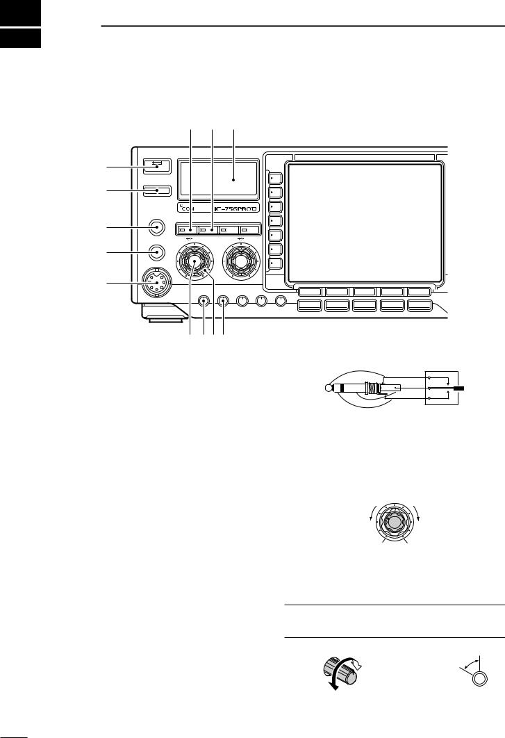
■ Front panel
q
w
e
r
t
TIMER
POWER |
TRANSMIT
PHONES
ELEC-KEY
MIC
!2 !1 !0
HF/50MHz TRANSCEIVER
TUNER MONITOR |
NB |
NR |
AF RF/SQL |
BAL |
NR |
F-1 |
F-2 |
F-3 |
F-4 |
F-5 |
SSB |
CW/RTTY AM/FM FILTER EXIT/SET |
MIC GAIN RF POWER COMP BK-IN DELAY KEY SPEED |
|
y uio |
|
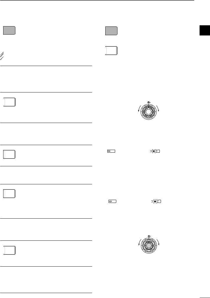
q POWER SWITCH [POWER•TIMER] |
(dot) |
While transceiver’s power is OFF: |
(com) |
Push to turn power ON. |
(dash) |
• Turn the optional DC power supply ON in advance. •A/D converter calibration of the DSP unit starts and it takes approx. 10 sec.
While transceiver’s power is ON:
Push momentarily to toggle the timer function ON and OFF. (p. 93)
•The [TIMER] indicator in this switch lights while the timer function is ON.
Push for 1 sec. to turn power OFF.
w TRANSMIT SWITCH [TRANSMIT]
t MICROPHONE CONNECTOR [MIC]
Accepts the supplied or optional microphone.
•See p. 116 for appropriate microphones.
•See p. 18 for microphone connector information.
y AF CONTROL [AF] (inner control)
Varies the audio output level from the speaker.
AF RF/SQL
Selects transmitting or receiving.
•The [TX] indicator lights red while transmitting and the [RX] indicator lights green when the squelch is open.
e HEADPHONE JACK [PHONES]
Accepts headphones.
•Output power: 5 mW with an 8 Ω load.
•When headphones are connected, the internal speaker or connected external speaker does not function.
r ELECTRONIC KEYER JACK [ELEC-KEY]
Accepts a paddle to activate the internal electronic keyer for CW operation. (p. 38)
Decreases |
Increases |
No audio output |
Max. audio output |
u MIC GAIN CONTROL [MIC GAIN]
Adjusts microphone input gain.
•The transmit audio tone in SSB mode can be adjusted in set mode. (p. 95)
How to set the microphone gain.
Set the [MIC] control so that the ALC meter sometimes swings during normal voice level transmission in SSB mode.
•Selection between the internal electronic keyer, bug-key |
Increases |
Recommended level for |
||
and straight key operation can be made in keyer set |
||||
|
an Icom microphone |
|||
mode. (p. 43) |
|
|
|
|
•A straight key jack is separately available on the rear |
Decreases |
|
|
|
|
|
|||
|
|
|||
panel. See [KEY] on p. 11. |
MIC GAIN |
|||
•Keyer polarity (dot and dash) can be reversed in keyer |
MIC GAIN |
|||
|
|
|
||
set mode. (p. 43) |
|
|
|
|
•4-channel memory keyer is available for your conve- |
|
|
|
|
nience. (p. 40) |
|
|
|
|
1
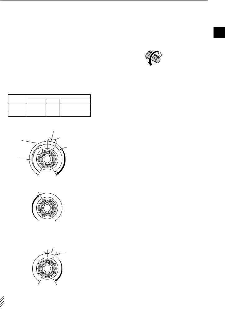
i RF GAIN CONTROL/SQUELCH CONTROL [RF/SQL] (outer control)
Adjusts the RF gain and squelch threshold level. The squelch removes noise output from the speaker (closed condition) when no signal is received.
•The squelch is particularly effective for FM. It is also available for other modes.
•12 to 1 o’clock position is recommended for any setting of the [RF/SQL] control.
•The control can be set as ‘Auto’ (RF gain control in SSB, CW and RTTY; squelch control in AM and FM) or squelch control (RF gain is fixed at maximum) in set mode as follows. (p. 99)
MODE |
SET MODE SETTING |
|||
AUTO |
SQL |
RF GAIN + SQL |
||
|
||||
SSB, CW |
RF GAIN |
SQL |
RF GAIN + SQL |
|
RTTY |
||||
|
|
|
||
AM, FM |
SQL |
SQL |
RF GAIN + SQL |
|
•When setting as RF gain/squelch control
|
Noise squelch (FM mode) |
Squelch is |
Recommended level |
|
|
open. |
Maximum |
|
|
|
RF gain |
RF gain |
|
adjustable |
S-meter |
range |
squelch |
•When functioning as RF gain control
(Squelch is fixed open; SSB, CW, RTTY only)
Maximum
RF gain
Adjustable range
Minimum RF gain 
•When functioning as squelch control
(RF gain is fixed at maximum.)
Noise squelch (FM mode)
Noise squelch
threshold  (FM mode)
S-meter squelch threshold
Squelch is |
S-meter |
|
squelch |
||
open. |
||
|
||
Shallow |
Deep |
 While rotating the RF gain control, noise may be
  heard. This comes from the DSP unit and does not
  indicate an equipment malfunction.
PANEL DESCRIPTION |
1 |
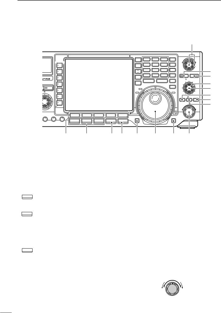
o RF POWER CONTROL [RF POWER]
Continuously varies the RF output power from min- 1 imum (5 W*) to maximum (100 W*).
*AM mode: 5 W to 40 W
|
Increases |
|
max. 100 W |
Decreases |
(40 W for AM) |
|
|
min. 5 W |
RF POWER |
!0S/RF METER (p. 31)
Shows the signal strength while receiving. Shows the relative output power, SWR, ALC or compression levels while transmitting.
!1MONITOR SWITCH [MONITOR] (p. 70) Monitors your transmitted IF signal.
•The CW side tone functions regardless of the [MONITOR] switch setting in CW mode.
•The [MONITOR] indicator in this switch lights green when the function is activated.
!2ANTENNA TUNER SWITCH [TUNER] (p. 89)
Turns the internal antenna tuner ON and OFF (bypass) when pushed momentarily.
Tunes the antenna manually when pushed for 1 sec.
•The [TUNER] indicator in this switch lights red when the function is activated or blinks during manual tuning.
•When the tuner cannot tune the antenna, the tuning circuit is bypassed automatically after 20 sec.
2
1 PANEL DESCRIPTION
■ Front panel (continued)
@0!9!8!7!6
TIMER |
HF/50MHz TRANSCEIVER |
POWER
TRANSMIT
PHONES |
TUNER MONITOR |
NB |
NR |
|
|
||||
ELEC-KEY |
AF |
RF/SQL |
BAL |
NR |
|
|
|
|
|
MIC
F-1 |
F-2 |
F-3 |
F-4 |
F-5 |
SSB |
CW/RTTY |
AM/FM |
FILTER |
EXIT/SET |
MIC GAIN RF POWER COMP BK-IN DELAY KEY SPEED
!3 !4 !5
!3COMPRESSION LEVEL CONTROL [COMP]
(p. 68)
Adjusts the speech compression level in SSB.
Compression
level increases
Compression
level decreases
COMP
!4SEMI BREAK-IN DELAY CONTROL [BK-IN DELAY]
Adjusts the transmit-to-receive switching delay time for CW semi break-in operation.
|
Long delay for |
|
slow speed keying |
Short delay for |
(13 dot) |
high speed keying |
|
(2 dot) |
BK-IN DELAY |
!5ELECTRONIC CW KEYER SPEED CONTROL [KEY SPEED] (p. 35)
Adjusts the internal electronic CW keyer’s speed.
• 6 wpm (min.) to 60 wpm (max.) can be set.
Fast
Slow
KEY SPEED
!6MULTI-FUNCTION SWITCHES
Push to select the functions indicated in the LCD display to the right of these switches.
•Functions vary depending on the operating condition.
ANT Selects the antenna connector between
1ANT1 and ANT2 when pushed. (p. 88)
Turns the [RX ANT] (receive antenna) ON and OFF when pushed for 1 sec.
•When the receive antenna is activated, the antenna which is connected to the [ANT1] or [ANT2] is used for transmission only.
 When a transverter is in use, this [ANT]
  does not function and ‘XVERT’ appears.
|
|
Selects RF power (Po), SWR, ALC or |
|
METER |
|
|
||
|
Po |
COMP metering during transmit. (p. 31) |
|
|
|
|
|
Switches the multi-function digital meter |
|
|
|
|
|
ON and OFF when pushed for 1 sec. |
|
|
Selects one of 2 receive RF preamps or |
|
P.AMP |
|
|
||
|
bypasses them. (p. 57) |
|
|
OFF |
|
|
|
|
|
|
•“P. AMP1” activates 10 dB preamp. |
|
|
|
|
|
•“P. AMP2” activates 16 dB high-gain preamp. |
What is the preamp?
The preamp amplifies received signals in the front end circuit to improve the S/N ratio and increase the sensitivity. Select “P. AMP1” or “P. AMP2” when receiving weak signals.
ATT |
Selects 6 dB, 12 dB or 18 dB attenuator, |
|
or bypasses them. (p. 57) |
||
OFF |
What is the attenuator?
The attenuator prevents a desired signal from distorting when very strong signals are near the desired frequency, or when very strong electric fields, such as from a broadcasting station, are near your location.
3
|
|
Activates or selects fast, middle or slow |
|
AGC |
|
|
||
|
AGC time constant when pushed. (p. 59) |
|
|
MID |
|
|
|
• “FAST” is only available for FM mode. |
|
|
|
|
|
Enters the AGC set mode when pushed |
|
|
for 1 sec. (p. 59) |
 AGC time constant can be set between 0.1 to
 8.0 sec. (depends on mode), or turned OFF. While
  “OFF” is selected, the S-meter does not function.
What is the AGC?
The AGC function controls receiver gain to produce a constant audio output level, even when the received signal strength is varied by fading, etc. Select “FAST” for tuning and select “MID” or “SLOW” depending on the receiving condition.
Turns the VOX function ON and OFF
VOX
OFF when pushed in a phone mode (SSB, AM or FM mode). (p. 66)
Enters the VOX set mode when pushed for 1 sec. in a phone mode. (p. 66)
What is the VOX function?
The VOX function (voice operated transmission) starts transmission without pushing the transmit switch or PTT switch when you speak into the microphone; then, automatically returns to receive when you stop speaking.
Selects semi break-in, full break-in oper-
BK-IN
OFF ation, or turns the break-in operation OFF when pushed in CW mode. (p. 67)
What is the break-in function?
The break-in function switches transmit and receive with CW keying. Full break-in function (QSK) can monitor the receive signal during keying.
RTTY Turns the RTTY filter ON and OFF in
FIL
OFF RTTY mode. (p. 45)
•When the RTTY filter is turned ON, [TWIN PBT] functions as the IF shift control.
Enters the RTTY filter set mode when pushed for 1 sec. in RTTY mode. (p. 45)
What is the IF shift?
The IF shift function electronically changes the center of the IF (Intermediate Frequency) passband frequency to reject interference. Only the inner control of [TWIN PBT] can be used for the IF shift control.
COMP Turns the speech compressor ON and
OFF
WIDE OFF in SSB mode. (p. 68)
Switches the narrow, middle or wide transmit filter when pushed for 1 sec.
What is the speech compressor?
The speech compressor compresses the transmitter audio input to increase the average audio output level. Therefore, talk power is increased. This function is effective for long distance communication or when propagation conditions are poor.
PANEL DESCRIPTION |
1 |
|
|
Turns the 1⁄4 function ON and OFF in |
1 |
|
1/4 |
||
|
|||
|
SSB data, CW and RTTY modes. (p. 27) |
||
|
OFF |
||
|
|
|
|
•1⁄4 function sets dial rotation to 1⁄4 of normal for fine tuning.
Switches the tone encoder, tone squelch
TONE
OFF function and no tone operation when pushed in FM mode. (pgs. 52, 53)
Enters the tone set mode when pushed for 1 sec. in FM mode. (pgs. 52, 53)
!7NOISE REDUCTION LEVEL CONTROL [NR]
(outer control; p. 65)
Adjusts the noise reduction level when the noise reduction is in use. Set for maximum readability.
•To activate this control, turn the noise reduction ON in advance (!8).
BAL |
NR |
Decreases |
Increases |
OFF 
!8NOISE REDUCTION SWITCH [NR] (p. 65) Push to switch the noise reduction ON and OFF.
•The [NR] indicator in this switch lights green when the function is activated.
NR |
NR |
Noise reduction OFF |
Noise reduction ON |
!9NOISE BLANKER SWITCH [NB] (p. 64)
Switches the noise blanker ON and OFF when pushed. The noise blanker reduces pulse-type noise such as that generated by automobile ignition systems. This function cannot be used for FM mode, or non-pulse-type noise.
•The [NB] indicator in this switch lights green when the
function is activated.
NB |
NB |
Noise blanker OFF |
Noise blanker ON |
Enters the noise blanker level set mode when pushed for 1 sec.
@0BALANCE CONTROL [BAL] (inner control; p. 63) Adjusts the audio output balance between main and sub readout frequencies while in dualwatch.
BAL |
NR |
Increases main |
Increases sub |
readout gain |
readout gain |
4
1 PANEL DESCRIPTION
■ Front panel (continued) |
|
|
#6 |
EIVER |
TWIN PBT |
|
|
|
|
|
SPLIT |
1.8 |
1 |
3.5 |
2 |
7 |
3 |
Y |
|
|
|
|
|
|
|
|
DUAL |
10 |
4 |
14 |
5 |
18 |
6 |
Z |
|
|
|
|
|
|
|
|
WATCH |
|
|
|
|
|
|
|
|
|
|
|
|
|
|
|
CHANGE |
21 |
7 |
24 |
8 |
28 |
9 |
MW |
|
|
#5 |
|
|
|
|
|
|
|
|
|
|
|
PBT CLR |
NOTCH |
|||
|
|
|
|
|
|
|
|
|
|
|
|
||||
|
|
|
|
|
VFO/ |
GENE • |
50 |
0 |
F-INPENT |
M-CL |
|
|
#4 |
||
|
|
|
|
|
|
|
|
|
|
|
|
|
|
|
|
|
|
|
|
|
MEMO |
|
|
|
|
|
|
NOTCH |
CW PITCH |
|
|
|
|
|
|
|
M.SCOPE |
|
MP-W |
|
MP-R |
|
|
||||
|
|
|
|
|
MAIN/ |
|
|
|
TS |
|
|
|
|||
NB |
NR |
|
|
|
|
|
|
|
|
|
|
|
|
#3 |
|
|
|
|
SUB |
|
|
|
|
|
|
|
|
|
|||
|
|
|
|
|
RX |
|
|
|
|
|
|
XFC |
|
|
#2 |
|
|
|
|
|
TX |
|
|
|
|
|
|
LOCK |
|
|
|
BAL |
NR |
|
|
|
|
|
|
|
|
|
|
|
|
||
|
|
|
|
|
|
|
|
|
|
|
|
|
|
||
|
|
|
|
|
|
|
|
|
|
|
|
RIT |
TX |
CLEAR |
#1 |
|
|
|
|
|
|
|
|
|
|
|
|
#0 |
|||
|
|
|
|
|
|
|
|
|
|
|
|
|
|
|
|
|
|
|
|
|
|
|
|
|
|
|
|
|
RIT/ TX |
@9 |
|
|
F-1 |
F-2 |
F-3 |
F-4 F-5 |
REC/PLAY |
|
|
|
|
|
|
LOCK/SPEECH |
|
|
|
|
|
|
|
|
|
|
|
|
|
|
|
|
|
||
|
SSB |
CW/RTTY |
AM/FM |
FILTER EXIT/SET |
|
|
|
|
|
|
|
|
|
|
|
|
COMP BK-IN DELAY KEY SPEED |
|
|
|
|
|
|
|
|
|
|
|
|
|
|
|
@1 |
@2 |
|
@3 @4 |
@5 |
|
|
@6 |
|
|
@7 |
@8 |
|
||
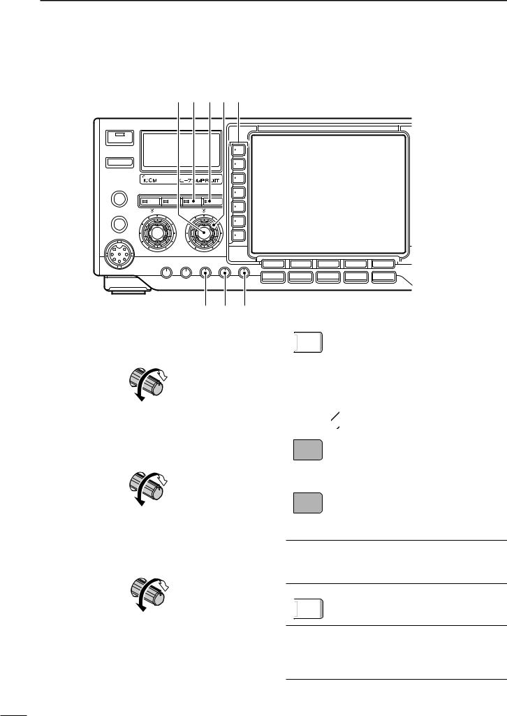
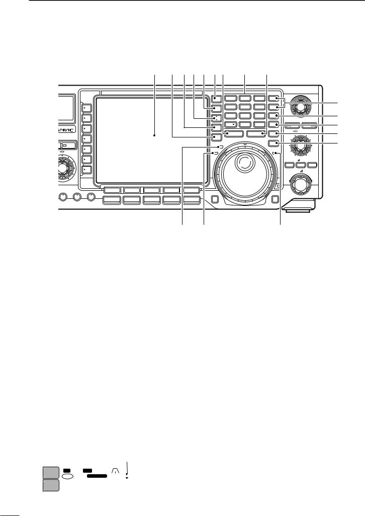
@1LCD FUNCTION SWITCHES [F-1]–[F-5]
Push to select the function indicated in the LCD display above these switches.
•Functions vary depending on the operating condition.
@2MODE SWITCHES
Selects the desired mode. (p. 29)
@5REC/PLAY SWITCH [REC/PLAY] (p. 73)
Push momentarily to playback the recorded contents in the channel R4 of the voice memory.
Push for 1 sec. to record the receiving signal contents into the channel R4 (max. 15 sec.) of the voice memory.
•Announces the selected mode when an optional UT-102 is installed. (pgs. 102, 105)
SSB Selects USB and LSB mode alternately.
Selects SSB data mode (USB-D, LSB-D) when pushed for 1 sec. in SSB mode.
CW/RTTY Selects CW and RTTY mode alternately.
Switches CW and CW-R (CW reverse) mode when pushed for 1 sec. in CW mode.
Switches RTTY and RTTY-R (RTTY reverse) mode when pushed for 1 sec. in RTTY mode.
AM/FM Selects AM and FM mode alternately.
Selects AM/FM data mode (AM-D, FM-D) when pushed for 1 sec. in AM or FM mode.
@3FILTER SWITCH [FILTER] (p. 61)
Push to select one of 3 IF filter settings.
Push for 1 sec. to enter the filter set mode.
@4EXIT/SET SWITCH [EXIT/SET]
Push to exit from a set mode, etc.
Push for 1 sec. to enter the set mode screen. (p. 94)
@6TUNING DIAL (p. 25)
Changes the displayed frequency, selects set mode settings, etc.
@7LOCK/SPEECH SWITCH [LOCK/SPEECH]
Push momentarily to toggle the dial lock function ON and OFF. (p. 65)
Push for 1 sec. to announce the S-meter indication and the selected readout frequency when an optional UT-102 is installed. (p. 105)
@8RIT/∂TX CONTROL [RIT/∂TX] (pgs. 58, 69) Shifts the receive and/or transmit frequency without changing the transmit and/or receive frequency while the RIT and/or ∂TX functions are ON.
•Rotate the control clockwise to increase the frequency, or rotate the control counterclockwise to decrease the frequency.
•The shift frequency range is ±9.999 kHz in 1 Hz steps (or ±9.99 kHz in 10 Hz steps).
|
RIT/∂TX |
Low shift |
High shift |
5
@9∂TX SWITCH [∂TX] (p. 69)
Turns the ∂TX function ON and OFF when pushed.
•Use the [RIT/∂TX] control to vary the ∂TX frequency.
Adds the ∂TX shift frequency to the operating frequency when pushed for 1 sec.
What is the ∂TX function?
The ∂TX shifts the transmit frequency without shifting the receive frequency. This is useful for simple split frequency operation in CW, etc.
#0CLEAR SWITCH [CLEAR] (pgs. 58, 69)
Clears the RIT/∂TX shift frequency when pushed for 1 sec. (default).
•The response time (for 1 sec. or momentarily) can be selected on the quick RIT/∂TX clear setting (p. 103).
#1RIT SWITCH [RIT] (p. 58)
Turns the RIT function ON and OFF when pushed.
•Use the [RIT/∂TX] control to vary the RIT frequency.
Adds the RIT shift frequency to the operating frequency when pushed for 1 sec.
What is the RIT function?
The RIT (Receiver Incremental Tuning) shifts the receive frequency without shifting the transmit frequency.
This is useful for fine tuning stations calling you on an off-fre- quency or when you prefer to listen to slightly differentsounding voice characteristics, etc.
#2MANUAL NOTCH FILTER CONTROL [NOTCH]
(inner control; p. 64)
Varies the peak frequency of the manual notch filter to pick out a receive signal from interference while the manual notch function is ON.
•Notch filter center frequency:
SSB |
: 0 Hz to 5100 Hz |
|
CW |
: CW pitch freq.–900 Hz to CW pitch freq. |
|
|
+4200 Hz |
|
AM |
: –5100 Hz to 5100 Hz |
|
|
NOTCH |
CW PITCH |
Lower frequency |
Higher frequency |
|
#3CW PITCH CONTROL [CW PITCH]
(outer control; p. 37)
Shifts the received CW audio pitch and monitored CW audio pitch without changing the operating frequency.
NOTCH |
CW PITCH |
Lower frequency |
Higher frequency |
Approx. 300 Hz |
Approx. 900 Hz |
PANEL DESCRIPTION |
1 |
#4NOTCH SWITCH [NOTCH] (p. 64)
Switches the notch function between auto, man- 1 ual and OFF in SSB and AM modes.
Turns the manual notch function ON and OFF when pushed in CW mode.
Turns the auto notch function ON and OFF when pushed in FM mode.
•“AN” appears on the display when auto notch is in use.
•“MN” appears on the display when manual notch is in use.
•The [NOTCH] indicator in this switch lights green
when the function is activated.
NOTCH |
NOTCH |
Notch OFF |
Notch ON |
What is the notch function?
The notch function eliminates unwanted CW or AM carrier tones while preserving the desired signal’s audio response. The filtering frequency is adjusted to effectively eliminate unwanted tones via the DSP circuit.
#5PBT CLEAR SWITCH [PBT CLR] (p. 60) Clears the PBT settings when pushed for 1 sec.
•The [PBT CLR] indicator in this switch lights green when PBT is in use.
#6PASSBAND TUNING CONTROLS [TWIN PBT]
Adjust the receiver’s “passband width” of the DSP filter. (p. 60)
•Passband width and shift frequency are displayed in the LCD.
•Push [PBT CLR] for 1 sec. to clear the settings when not in use.
•Variable range is set to half of the IF filter passband width. 25 Hz steps and 50 Hz steps are available. •These controls function as an IF shift control while in AM mode and when the RTTY filter is turned ON. Only the inner control may function in this case.
What is the PBT control?
General PBT function electronically narrows the IF passband width to reject interference. This transceiver uses the DSP circuit for the PBT function.
TWIN PBT
|
|
PBT1 |
|
|
PBT2 |
TWIN PBT |
TWIN PBT |
TWIN PBT |
– |
|
+ |
Low cut |
Center |
High cut |
6
1 PANEL DESCRIPTION
■ Front panel (continued) |
|
|
|
|
|
|
|
|
|
|
|
|
|
|
||
|
|
|
%3 %2%1%0$9$8$7 |
|
$6 |
|
$5 |
|
|
|
|
|||||
CEIVER |
|
|
|
|
|
|
|
|
|
|
|
TWIN PBT |
|
|
||
|
|
|
|
|
SPLIT |
1.8 |
1 |
3.5 |
2 |
7 |
3 |
Y |
|
|
|
$4 |
|
|
|
|
|
|
10 |
4 |
14 |
5 |
18 |
6 |
Z |
|
|
|
|
|
|
|
|
|
DUAL |
|
|
|
|
|||||||
|
|
|
|
|
WATCH |
|
|
|
|
|
|
|
|
|
|
|
|
|
|
|
|
CHANGE |
21 |
7 |
24 |
8 |
28 |
9 |
MW |
|
|
|
$3 |
|
|
|
|
|
|
|
|
|
|
|
|
PBT CLR |
NOTCH |
$2 |
||
|
|
|
|
|
VFO/ |
GENE |
|
50 |
0 |
F-INPENT |
M-CL |
|
|
|
||
|
|
|
|
|
MEMO |
|
|
|
|
|
|
NOTCH |
CW PITCH |
|
||
|
|
|
|
|
M.SCOPE |
MP-W |
|
MP-R |
|
$1 |
||||||
|
|
|
|
|
MAIN/ |
|
|
TS |
|
|
|
|||||
NB |
NR |
|
|
|
|
|
|
|
|
|
|
|
|
|
||
|
|
|
SUB |
|
|
|
|
|
|
|
|
|
|
|
||
|
|
|
|
|
RX |
|
|
|
|
|
|
XFC |
|
|
|
$0 |
BAL |
NR |
|
|
|
TX |
|
|
|
|
|
|
LOCK |
|
|
|
|
|
|
|
|
|
|
|
|
|
|
|
|
|
|
|
||
|
|
|
|
|
|
|
|
|
|
|
|
RIT |
|
TX |
CLEAR |
|
|
|
|
|
|
|
|
|
|
|
|
|
|
RIT/ |
TX |
|
|
|
F-1 |
F-2 |
F-3 |
F-4 F-5 |
|
|
|
|
|
|
|
|
|
|
|
|
|
|
|
|
|
REC/PLAY |
|
|
|
|
|
|
LOCK/SPEECH |
|
|
|
|
|
SSB |
CW/RTTY |
AM/FM |
FILTER |
EXIT/SET |
|
|
|
|
|
|
|
|
|
|
|
|
COMP BK-IN DELAY KEY SPEED |
|
|
|
|
|
|
|
|
|
|
|
|
|
|
|
#7 |
#8 |
#9 |
#7RECEIVE INDICATOR [RX] |
|
When the quick tuning step is OFF, push for 1 |
Lights green while receiving a signal and when the |
|
sec. to turn the 1 Hz tuning step ON and OFF. |
squelch is open. |
|
•1 Hz indications appear in both readouts and the fre- |
#8TRANSMIT INDICATOR [TX] |
|
quency can be changed in 1 Hz steps. |
|
When the quick tuning step is ON, push for 1 sec. |
|
Lights red while transmitting. |
|
to enter the quick tuning step set mode. |
#9LOCK INDICATOR [LOCK] (p. 65) |
$2MEMORY CLEAR SWITCH [M-CL] (p. 81) |
|
Lights red when the dial lock function is activated. |
|
Clears the selected readout memory channel con- |
$0TRANSMIT FREQUENCY CHECK SWITCH |
|
tents when pushed for 1 sec. in memory mode. |
|
•The channel becomes a blank channel. |
|
[XFC] |
|
|
|
•This switch does not function in VFO mode. |
|
Monitors the transmit frequency when pushed and |
|
|
|
|
|
held during the split frequency operation. |
$3MEMORY WRITE SWITCH [MW] (p. 79) |
|
•While pushing this switch, the transmit frequency can be |
|
Stores the selected readout frequency and operat- |
changed with the tuning dial, keypad, memo pad or the |
|
ing mode into the displayed memory channel when |
[Y]/[Z] switches. |
|
pushed for 1 sec. |
•When the split lock function is turned ON, pushing [XFC] |
•This function is available both in VFO and memory |
|
cancels the dial lock function. (p. 100) |
||
modes. |
||
|
$1QUICK TUNING SWITCH [TS] (p. 26) |
$4MEMORY UP/DOWN SWITCHES [Y]/[Z] (p. 77) |
|
Turns the quick tuning step ON and OFF. |
||
Push to select the memory channel number for |
||
•While the quick tuning indicator, “Z,” is displayed |
||
the selected readout. |
||
above the frequency indication, the frequency can be |
||
•Memory channels can be selected both in VFO and |
||
changed in programmed kHz steps. |
||
memory modes. |
||
•0.1, 1, 5, 9, 10, 12.5, 20 and 25 kHz quick tuning |
||
Select the desired memory channel directly after |
||
steps are available for each operating mode indepen- |
||
pushing [(F-INP)ENT] and a memory channel |
||
dently. |
||
number. |
||
|
|
|
|
|
|
Quick tuning indicator |
||||
|
|
|
|
||||||
|
ANT |
BW 2.4k SFT 0 |
qw:pp |
||||||
|
1 |
|
|
|
|
|
|
|
12:00 |
|
TX VFO |
USB FIL2 |
|||||||
|
|
|
|||||||
|
|
|
qr.qpp.pp |
||||||
|
METER |
|
|||||||
|
|
||||||||
|
Po |
|
|
|
|
|
|
|
|
|
|
1 |
|
21.076.50 |
|
CW |
|||
|
|
|
|
||||||
|
|
|
|
|
|
|
|
|
|
$5MEMO PAD-READ SWITCH [MP-R] (p. 82)
Each pushing calls up a frequency and operating mode in a memo pad. The 5 (or 10) most recently programmed frequencies and operating modes can be recalled, starting from the most recent.
•The memo pad capacity can be expanded from 5 to 10 in set mode for your convenience. (p. 102)
7

$6KEYPAD
Pushing a key selects the operating band.
•[(GENE)•] selects the general coverage band.
Pushing the same key 2 or 3 times calls up other stacked frequencies in the band. (p. 24)
•Icom’s triple band stacking register memorizes 3 frequencies in each band.
After pushing [(F-INP)ENT], enters a keyed frequency or memory channel. Pushing [(F- INP)ENT] or [Y]/[Z] is necessary at the end. (pgs. 25, 77)
•e.g. to enter 14.195 MHz, push [(F-INP)ENT] [1] [4] [•] [1] [9] [5] [(F-INP)ENT].
$7MEMO PAD-WRITE SWITCH [MP-W] (p. 82) Programs the selected readout frequency and operating mode into a memo pad.
•The 5 most recent entries remain in memo pads.
•The transmit frequency is programmed when pushed together with [XFC].
•The memo pad capacity can be expanded from 5 to 10 in set mode for your convenience. (p. 102)
$8SPLIT SWITCH [SPLIT] (p. 71)
Turns the split function ON and OFF when pushed.
Turns the split function ON, equalizes the sub readout frequency to the main readout and sets the sub readout for frequency input when pushed for 1 sec. in non-FM modes. (Quick split function)
•The offset frequency is shifted from the main readout frequency in FM mode. (pgs. 52, 100)
•The quick split function can be turned OFF using set mode. (p. 100)
Turns the split function ON and shifts the sub readout frequency after input an offset (±4 MHz in 1 kHz steps).
$9DUALWATCH SWITCH [DUALWATCH] (p. 63)
Turns the dualwatch function ON and OFF when pushed.
Turns the dualwatch function ON and equalizes the sub readout frequency to the main readout when pushed for 1 sec. (Quick dualwatch function) •The quick dualwatch function can be turned OFF
using set mode. (p. 98)
%0MAIN/SUB CHANGE SWITCH [CHANGE]
Switches the frequency and selected memory channel between main and sub readouts when pushed.
•Switches between transmit frequency and receive frequency when the split frequency function is ON. (p. 71)
Equalizes the sub readout frequency to the main readout frequency when pushed for 1 sec.
PANEL DESCRIPTION |
1 |
%1VFO/MEMORY SWITCH [VFO/MEMO]
Switches the selected readout operating mode 1 between the VFO mode and memory mode when pushed. (pgs. 23, 77)
Transfers the memory contents to VFO when pushed for 1 sec. (p. 80)
%2MAIN/SUB•M.SCOPE SWITCH [MAIN/SUB•M.SCOPE]
Push momentarily to select access to the main or sub readout. (p. 23)
•The sub readout frequency is displayed in outline or mesh font. The sub readout functions only during split operation or dualwatch.
Push for 1 sec. to turn the mini spectrum scope screen indication ON and OFF. (p. 55)
•The mini spectrum scope screen can be indicated with another screen, such as memory, set mode screen, simultaneously.
%3LCD FUNCTION DISPLAY (See p. 9 for details.) Shows the operating frequency, function switch menus, spectrum scope screen, memory channel screen, set mode settings, etc.
8
1 PANEL DESCRIPTION
■ LCD display
|
|
!6!5 |
!4!3!2 !1 !0 |
o |
|
||
|
ANT |
BW 2.4k SFT |
0 |
|
|
qw:pp |
|
q |
1 |
TX VFO |
USB |
FIL2 |
|
23:00 |
|
|
|
|
|
||||
w |
METER |
qr.qqy.pp |
i |
||||
|
Po |
|
|
|
|
|
u |
e |
|
1ß |
21.085.00 |
CW |
|
||
P.AMP |
|
|
|
|
|
|
|
w |
56ß USB |
FIL2 |
|
|
|
||
1 |
|
|
|
||||
|
|
|
|
|
|
|
|
|
ATT |
qr.qpp.pp |
|
i |
|||
|
OFF |
VFO |
21.085.00 |
CW |
|
u |
|
|
|
|
|||||
|
AGC |
-12.5k |
|
SPECTRUM SCOPE |
+12.5k |
|
|
|
Grid |
|
|
|
|
|
|
r |
MID |
|
|
|
|
|
|
|
10k |
|
|
|
|
|
|
|
|
10dB |
|
|
|
|
|
|
VOX |
ATT |
|
|
|
|
y |
|
OFF |
|
|
|
|
||
|
10dB |
|
|
|
|
|
|
|
COMP |
SUB |
|
|
|
|
|
|
MARKER |
|
|
|
|
|
|
|
OFF |
|
|
|
|
|
|
|
HOLD |
|
|
|
|
|
|
|
WIDE |
|
|
|
|
|
|
|
SPAN |
ATT |
MARKER |
HOLD |
SET |
|
|
|
|
|
|
t |
|
|
|
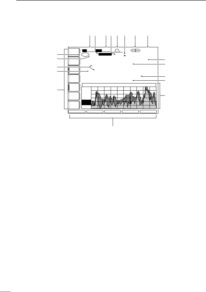
q TX INDICATOR
Indicates the frequency readout for transmission.
w VFO/MEMORY CHANNEL INDICATOR
(pgs. 23, 77)
Indicates the VFO mode or selected memory channel number.
e SELECT MEMORY CHANNEL INDICATOR (p. 86) Indicates the displayed memory channel is set as a select memory channel.
r MULTI-FUNCTION SWITCH GUIDE
Indicates the function of the multi-function switches.
t LCD FUNCTION SWITCH GUIDE
Indicates the function of the LCD function switches ([F-1] – [F-5]).
y MULTI-FUNCTION SCREEN (p. 10)
Shows the screens for the multi-function digital meter, spectrum scope, voice recorder, memory channel, scan, memory keyer, RTTY decoder, IF filter selection or set modes, etc.
u MEMORY CHANNEL READOUTS (p. 77)
Show the selected memory channel contents in VFO mode.
Show the VFO contents in memory mode.
i FREQUENCY READOUTS (p. 25) Show the operating frequency.
•Outline characters are used for non-accessing readout.
o CLOCK READOUT (p. 92) Shows the current time.
•Dualtime indication is available.
!0RTTY TUNING INDICATOR (p. 47) Shows the tuning level in RTTY mode.
!1QUICK TUNING INDICATOR (p. 26)
Appears when the quick tuning step function is in use.
!2PASSBAND WIDTH INDICATOR (pgs. 60, 61) Graphically displays the passband width for twin PBT operation and center frequency for IF shift operation.
!3IF FILTER INDICATOR (p. 61) Shows the selected IF filter number.
!4SHIFT FREQUENCY INDICATOR (p. 60) Shows the shift frequency of the IF filter.
!5MODE INDICATOR (p. 29)
Shows the selected mode.
!6BAND WIDTH INDICATOR (p. 61) Shows the passband width of the IF filter.
9
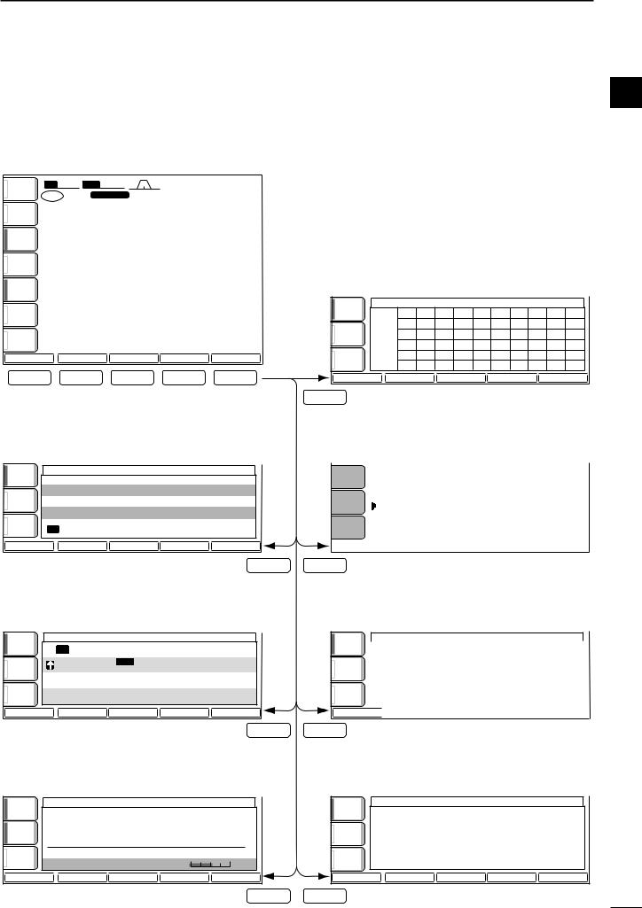
■ Screen menu arrangement
The following screens can be selected from the start up screen. Choose the desired screen using the following chart.
• Start up screen
ANT BW 2.4k SFT |
0 |
|
qw:pp |
|
1 |
|
|
12:00 |
|
TX VFO |
CW |
FIL2 |
||
|
METER |
qr.qpp.pp |
|||
Po |
1 |
--. ---. -- |
CW |
|
|
|
|||
P.AMP |
|
|
|
|
1 |
VFO |
USB FIL2 |
|
|
ATT |
qr.qpp.pp |
|
||
0FF |
1 --. ---. -- |
CW |
|
|
|
|
|||
AGC |
|
|
|
|
MID |
|
|
|
|
BK-IN |
|
|
|
|
OFF |
|
|
|
|
1/4 |
|
|
|
|
OFF |
|
|
|
|
SCOPE |
VOICE |
KEYER |
MEMORY |
SCAN |
F-1 |
F-2 |
F-3 |
F-4 |
F-5 |
• Voice recorder screen (p. 73)
AGC |
|
VOICE RECORDER |
|
|
|
|
|
|
|
MID |
T1 |
|
|
- - - |
|
T2 |
|
|
- - - |
BK-IN |
T3 |
|
|
- - - |
OFF |
|
|
||
|
|
|
|
|
|
T4 |
|
|
- - - |
1/4 |
TX M E M O R Y |
|
|
|
OFF |
|
|
|
|
T1 |
T2 |
T3 |
T4 |
T/R |
F-2
• Memory keyer screen (CW mode: p. 40)
AGC |
|
|
MEMORY KEYER |
|
|
|
C Q T E S T C Q T E S T D E I C O M I C O M |
||||
MID |
M 1 |
||||
|
T E S T |
|
|
|
|
|
|
|
|
|
|
BK-IN |
M 2 |
U R 5 N N 0 0 1 |
B K |
|
|
|
|
|
|
||
OFF |
|
C F M |
T U |
|
|
|
M 3 |
|
|
||
|
|
|
|
|
|
1/4 |
M 4 |
Q R Z ? |
|
|
|
OFF |
|
|
|
||
|
|
|
|
||
|
|
|
|
|
|
M1 |
|
M2 |
M3 |
M4 |
-1 |
F-3
PANEL DESCRIPTION |
1 |
1
Pushing [EXIT/SET] several times returns to the start up screen. See p. 94 for set mode arrangement.
• Spectrum scope screen (p. 55)
AGC |
-12. 5k |
SPECTRUM |
SCOPE |
+12. 5k |
|
|
|
|
|
MID |
Grid |
|
|
|
|
2.5k |
|
|
|
|
10dB |
|
|
|
BK-IN |
|
|
|
|
OFF |
|
|
|
|
1/4 |
|
|
|
|
OFF |
|
|
|
|
SPAN |
ATT |
MARKER |
HOLD |
SET |
F-1
• Memory channel screen (p. 78)
|
|
AGC |
|
|
|
|
|
|
M E M O R Y |
|
|
|
|
|
|
|
|
|
|
|
|
|
|
|
|
|
|
|
|
|
|
|
|
MID |
|
|
9 9 |
- - . - - - . - - ------ |
- - - |
|
|
|
|
|
|||
|
|
|
|
|
P 1 0 0 . 5 0 0 . 0 0 U S B |
F L 2 |
S C A N E D G E |
|
|
||||||
|
|
|
|
|
|
|
|||||||||
|
|
BK-IN |
|
|
P 2 2 9 . 9 9 9 . 9 9 U S B |
F L 2 |
S C A N E D G E |
|
|
||||||
|
|
|
|
|
|
||||||||||
|
|
|
|
|
|
|
|
|
|
|
|
|
|
|
|
|
|
OFF |
|
|
1 |
- - . - - - . - - ------ |
- - - |
|
|
|
|
|
|||
|
|
|
|
|
|
|
|
|
|
|
|
|
|
|
|
|
|
|
|
|
2 |
- - . - - - . - - ------ |
- - - |
|
|
|
|
|
|||
|
|
|
|
|
|
|
|
|
|
||||||
|
|
|
|
|
|
|
|
|
|
||||||
|
|
1/4 |
|
|
3 |
- - . - - - . - - ------ |
- - - |
|
|
|
|
|
|||
|
|
OFF |
|
|
4 |
- - . - - - . - - ------ |
- - - |
|
|
|
|
|
|||
|
|
|
|
|
|
|
|
|
|
|
|
|
|
|
|
|
|
|
|
|
|
|
|
|
|
|
|
|
|
||
|
|
ROLL |
|
|
SET |
|
SELECT |
NAME |
|
|
WIDE |
|
|
||
F-4
• Programmed scan screen (VFO mode: p. 84)
AGC
MID
BK-IN
OFF
1/4 OFF
PROG
F-5
SCAN
|
|
∂ F S p a n |
: ± |
1 0 k H z |
|
|
||||
|
|
P r o g r a m m e d P 1 : |
|
0 . 5 0 0 . 0 0 M H z |
|
|
||||
|
|
s c a n e d g e s P 2 : |
2 9 . 9 9 9 . 9 9 M H z |
|
|
|||||
|
|
|
|
|
|
|
|
|
|
|
|
|
|
|
|
|
|
|
|
|
|
|
|
∂F |
|
FINE |
|
∂F SPAN |
|
SET |
|
|
• RTTY decoder screen (RTTY mode: p. 46)
AGC |
|
RTTY DECODE |
|
|
|
|
|
|
|
MID |
**** RTTY Decode Monitor **** |
|
||
|
45bps BAUDOT |
Mark=2125,Shift=170 |
|
|
RTTY |
UnShift On Space support (SET-OTHERS) |
|||
FIL |
New Line Code selectable (SET-OTHERS) |
|||
ON |
If RTTY-FIL is OFF, Please turn ON. |
|
||
1/4 |
|
|
|
|
OFF |
|
THRESHOLD |
9 |
|
|
|
|||
<MENU1> |
HLD/CLR |
TX MEM |
ADJ |
WIDE |
• Memory scan screen (Memory mode: p. 85)
|
AGC |
|
|
|
SCAN |
|
|
|
|
|
|
|
|
|
|
|
MID |
|
|
|
|
|
|
|
BK-IN |
|
|
|
|
|
|
|
OFF |
∂ F |
S p a n |
: ± |
1 0 k H z |
|
|
|
|
|
|||||
|
1/4 |
P r o g r a m m e d P 1 : |
0 . 5 0 0 . 0 0 M H z |
|
|||
|
s c a n e d g e s P 2 : 2 9 . 9 9 9 . 9 9 M H z |
|
|||||
|
OFF |
|
|||||
|
|
|
|
|
|
|
|
|
MEMO |
|
∂F |
SELECT |
∂F SPAN |
SET |
|
F-3 |
F-5 |
|
|
|
|
|
|
10
1 PANEL DESCRIPTION
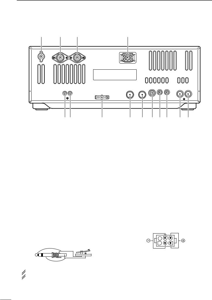
■ Rear panel
!4 !3 !2
q w |
e |
q TRANSVERTER JACK [XVERT] (p. 18)
External transverter input/output jack. Activated by voltage applied to [ACC(2)] pin 6.
w RECEIVE ANTENNA CONNECTOR [RX ANT]
(p. 15)
Connects a 50 Ω general coverage antenna with an RCA connector.
e TUNER CONTROL SOCKET [TUNER] (p. 15) Accepts the control cable from an optional AH-4
HF/50 MHz AUTOMATIC ANTENNA TUNER or AH-3 HF AUTOMATIC ANTENNA TUNER.
r ACCESSORY SOCKET 1 [ACC(1)] t ACCESSORY SOCKET 2 [ACC(2)]
Enable connection of external equipment such as a linear amplifier, an automatic antenna selector/ tuner, TNC for data communications, etc.
•See p. 20 for socket information.
y STRAIGHT KEY JACK [KEY] (p. 14)
Accepts a straight key or external electronic keyer with 1⁄4 inch standard plug.
•[ELEC-KEY] on the front panel can be used for a straight key or external electronic keyer. Deactivate the internal electronic keyer in keyer set mode. (p. 43)
(+)
(_)
 If you use an external electronic keyer, make
  sure the voltage retained by the keyer is less
  than 0.4 V when the key is ON.
!1
r t y u i o !0
u CI-V REMOTE CONTROL JACK [REMOTE]
(p. 110)
Connects a PC via the optional CT-17 CI-V LEVEL CONVERTER for external control of the transceiver functions.
Used for transceive operation with another Icom CI-V transceiver or receiver.
iEXTERNAL SPEAKER JACK [EXT SP]
(pgs. 15, 116)
Accepts an 4–8 Ω speaker.
o ALC INPUT JACK [ALC] (p. 17)
Connects to the ALC output jack of a non-Icom linear amplifier.
!0SEND CONTROL JACK [SEND] (p. 17)
Goes to ground while transmitting to control external equipment such as a linear amplifier.
•Max. control level: 16 V DC/0.5 A
!1DC POWER SOCKET [DC 13.8V] (p. 16)
Accepts 13.8 V DC through the supplied DC power cable (OPC-025D).
Rear panel view
11
PANEL DESCRIPTION |
1 |
!2ANTENNA CONNECTOR 1 |
[ANT1] |
!4GROUND TERMINAL [GND] (pgs. 13, 14) |
1 |
!3ANTENNA CONNECTOR 2 |
[ANT2] (pgs. 13, 14) |
Connect this terminal to a ground to prevent electri- |
|
Accept a 50 Ω antenna with a PL-259 connector. |
cal shocks, TVI, BCI and other problems. |
|
|
|
|||
 When using an optional AH-4 HF/50 MHz AUTO-
MATIC ANTENNA TUNER or AH-3 HF AUTOMATIC AN-
 TENNA TUNER, connect it to the [ANT1] connector.
The internal antenna tuner activates for [ANT2] and
 deactivates for [ANT1] when connecting the AH-4
  or AH-3.
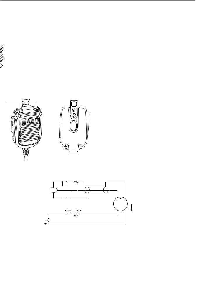
■ Microphone (HM-36)
q
w
• HM-36 SCHEMATIC DIAGRAM
q UP/DOWN SWITCHES [UP]/[DN]
Change the selected readout frequency or memory channel.
•Continuous pushing changes the frequency or memory channel number continuously.
•While pushing [XFC], the transmit readout frequency can be controlled while in spilt frequency operation. •The [UP]/[DN] switch can simulate a key paddle. Preset in the keyer set mode. (p. 43)
w PTT SWITCH
Push and hold to transmit; release to receive.
MICROPHONE |
MICROPHONE CABLE MICROPHONE PLUG |
+2k
10 |
|
|
|
4700p |
|||||||
|
|
|
|
|
|
|
|
|
|
|
+ |
MIC |
|
|
|
|
|
|
0.33 |
||||
ELEMENT |
|
|
|
|
|
|
4700p |
||||
|
|
|
|
|
|
|
|
|
|
|
|
|
q u |
|
w i y |
DOWN UP |
e r t |
PTT |
RECEIVE |
470 |
|
TRANSMIT
12

2 INSTALLATION AND CONNECTIONS
■ Unpacking |
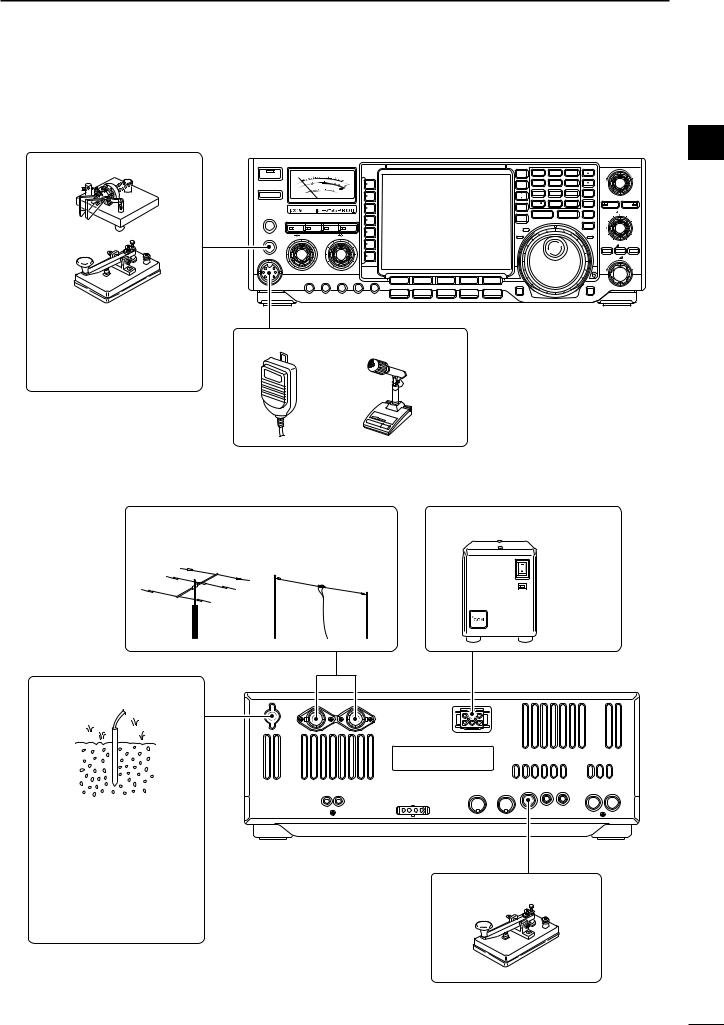
■ Antenna connection |
After unpacking, immediately report any damage to the delivering carrier or dealer. Keep the shipping cartons.
For a description and a diagram of accessory equipment included with the IC-756PROIII, see ‘Supplied accessories’ on p. i of this manual.
■ Selecting a location
Select a location for the transceiver that allows adequate air circulation, free from extreme heat, cold, or vibrations, and away from TV sets, TV antenna elements, radios and other electromagnetic sources.
The base of the transceiver has an adjustable stand for desktop use. Set the stand to one of two angles depending on your operating conditions.
■ Grounding
To prevent electrical shock, television interference (TVI), broadcast interference (BCI) and other problems, ground the transceiver through the GROUND terminal on the rear panel.
For best results, connect a heavy gauge wire or strap to a long earth-sunk copper rod. Make the distance between the [GND] terminal and ground as short as possible.
 RWARNING: NEVER connect the [GND]
terminal to a gas or electric pipe, since the connec-  tion could cause an explosion or electric shock.
For radio communications, the antenna is of critical importance, along with output power and sensitivity. Select antenna(s), such as a well-matched 50 Ω antenna, and feedline. 1.5:1 or better of Voltage Standing Wave Ratio (VSWR) is recommended for your desired band. Of course, the transmission line should be a coaxial cable.
When using 1 antenna, use the [ANT1] connector.
 CAUTION: Protect your transceiver from lightning
  by using a lightning arrestor.
PL-259 CONNECTOR INSTALLATION EXAMPLE
q |
|
30 mm |
|
|
|||||||
|
|
|
|
|
|
|
|
|
|
|
|
|
|
|
|
|
|
|
|
|
|
|
|
|
|
|
|
|
|
|
|
|
|
|
|
|
|
|
|
|
|
|
|
|
|
||
|
|
|
|
|
|
|
|
|
|
|
|
Coupling ring |
10 mm (soft solder) |
||||||||||
w |
10 mm |
Soft |
|||||||||
|
|
|
|
|
|
|
|||||
|
|
|
|
|
|
|
solder |
||||
|
|
|
|
|
|
|
|
|
|
|
|
|
|
|
|
|
|
|
|
|
|
|
|
|
|
|
|
|
|
|
|
|
|
|
|
|
|
|
|
|
1–2 mm |
||||||
e |
|
solder solder |
|||||||||
|
|
|
|
|
|
|
|
||||
|
|
|
|
|
|
|
|
|
|
|
|
r
Slide the coupling ring down. Strip the cable jacket and soft solder.
Strip the cable as shown at left. Soft solder the center conductor.
Slide the connector body on and solder it.
Screw the coupling ring onto the connector body.
30 mm ≈ 9⁄8 in 10 mm ≈ 3⁄8 in 1–2 mm ≈ 1⁄16 in
Antenna SWR
Each antenna is tuned for a specified frequency range and SWR may be increased out-of-range. When the SWR is higher than approx. 2.0:1, the transceiver’s power drops to protect the final transistor. In this case, an antenna tuner is useful to match the transceiver and antenna. Low SWR allows full power for transmitting even when using the antenna tuner. The IC-756PROIII has an SWR meter to monitor the antenna SWR continuously.
13
INSTALLATION AND CONNECTIONS |
2 |
■ Required connections
•Front panel
CW KEY
A straight key can be used when the internal electronic keyer is turned OFF in keyer set mode. (p. 43)
2
TIMER |
|
HF/50MHz TRANSCEIVER |
|
|
|
|
|
|
|
|
|
|
TWIN PBT |
|||||
POWER |
|
|
5 |
9 |
+ 20 |
+ 40 |
|
|
|
SPLIT |
1.8 |
1 |
3.5 |
2 |
7 |
3 |
|
|
|
|
1 |
10 |
25 |
50 |
+ 60dB |
|
|
|
|
|
|
|
|
|
|
|
|
|
|
|
|
|
|
|
|
|
|
|
|
|
|
|
|
|||
|
S |
0 |
|
100 |
|
|
|
DUAL |
10 |
4 |
14 |
5 |
18 |
6 |
|
|
||
TRANSMIT |
|
Po |
1.5 |
2 3 |
|
|
|
|
|
WATCH |
|
|
|
|
|
|
|
|
|
SWR |
1 0 |
10 |
20 |
|
|
|
|
|
|
|
|
|
|
|
|
|
|
|
|
COMP |
|
|
dB |
|
|
|
|
21 |
7 |
24 |
8 |
28 |
9 |
MW |
|
|
|
|
|
ALC |
|
|
|
|
|
|
CHANGE |
|
|||||||
|
|
|
|
|
|
|
|
|
|
|
|
|
|
|
|
|
|
|
|
|
|
|
|
|
|
|
|
|
|
|
|
|
|
|
|
PBT CLR |
NOTCH |
|
|
|
|
|
|
|
|
|
|
|
GENE |
50 |
0 |
F-INP |
ENT |
M-CL |
|
|
|
|
|
|
|
|
|
|
|
|
VFO/ |
|
|
||||||
|
|
|
|
|
|
|
|
|
|
|
|
|
|
|
|
|
|
|
|
|
|
|
|
|
|
|
|
|
MEMO |
|
|
|
|
|
|
NOTCH |
CW PITCH |
|
|
|
|
|
|
|
|
|
|
M.SCOPE |
|
MP-W |
|
|
MP-R |
|
||
PHONES |
|
|
|
|
|
|
|
|
|
MAIN/ |
|
|
|
|
TS |
|
||
TUNER MONITOR |
NB |
NR |
|
|
|
|
|
|
|
|
|
|
|
|||||
|
|
|
|
SUB |
|
|
|
|
|
|
|
|
||||||
|
|
|
|
|
|
|
|
|
|
RX |
|
|
|
|
|
|
XFC |
|
|
AF |
RF/SQL |
|
BAL NR |
|
|
|
TX |
|
|
|
|
|
|
LOCK |
|
||
ELEC-KEY |
|
|
|
|
|
|
|
|
|
|
|
|
|
|||||
|
|
|
|
|
|
|
|
|
|
|
|
|
|
|
|
|
|
|
|
|
|
|
|
|
|
|
|
|
|
|
|
|
|
|
|
RIT |
TX CLEAR |
MIC |
|
|
|
|
|
|
|
|
|
|
|
|
|
|
|
|
RIT/ |
TX |
|
|
|
|
|
|
F-1 |
F-2 |
F-3 |
F-4 |
F-5 |
|
|
|
|
|
|
|
|
|
|
|
|
|
|
|
|
|
|
REC/PLAY |
|
|
|
|
|
|
LOCK/SPEECH |
|
|
|
|
|
|
|
SSB |
CW/RTTY |
AM/FM |
FILTER |
EXIT/SET |
|
|
|
|
|
|
|
|
|
|
MIC GAIN RF POWER |
COMP BK-IN DELAY KEY SPEED |
|
|
|
|
|
|
|
|
|
|
|
|
|||
MICROPHONES (p. 116)
HM-36 |
SM-20 |
•Rear panel
ANTENNA 1, 2 (p. 13) |
DC POWER SUPPLY (p.16) |
[Example]: ANT1 for 1.8–18 MHz bands |
|
ANT2 for 21–50 MHz bands |
|
|
PS-125 |
GROUND (p. 13)
Use the heaviest gauge wire or strap available and make the connection as short as possible.
STRAIGHT KEY
Grounding prevents electrical shocks, TVI and other problems.
14

2 INSTALLATION AND CONNECTIONS
■ Advanced connections
•Front panel
HEADPHONES
TIMER |
|
HF/50MHz TRANSCEIVER |
|
|
|
|
|
|
|
|
|
|
TWIN PBT |
|||||
POWER |
|
|
5 |
9 |
+ 20 |
+ 40 |
|
|
|
SPLIT |
1.8 |
1 |
3.5 |
2 |
7 |
3 |
|
|
|
|
1 |
10 |
25 |
50 |
+ 60dB |
|
|
|
|
|
|
|
|
|
|
|
|
|
S |
0 |
|
100 |
|
|
|
DUAL |
10 |
4 |
14 |
5 |
18 |
6 |
|
|
||
TRANSMIT |
|
Po |
1.5 |
2 3 |
|
|
|
|
|
WATCH |
|
|
|
|
|
|
|
|
|
SWR |
1 0 |
10 |
20 |
|
|
|
|
|
|
|
|
|
|
|
|
|
|
|
|
COMP |
|
|
dB |
|
|
|
|
21 |
7 |
24 |
8 |
28 |
9 |
MW |
|
|
|
|
|
ALC |
|
|
|
|
|
|
CHANGE |
|
|||||||
|
|
|
|
|
|
|
|
|
|
|
|
|
|
|
|
|
|
|
|
|
|
|
|
|
|
|
|
|
|
|
|
|
|
|
|
PBT CLR |
NOTCH |
|
|
|
|
|
|
|
|
|
|
|
GENE |
50 |
0 |
F-INP |
ENT |
M-CL |
|
|
|
|
|
|
|
|
|
|
|
|
VFO/ |
|
|
||||||
|
|
|
|
|
|
|
|
|
|
|
|
|
|
|
|
|
|
|
|
|
|
|
|
|
|
|
|
|
MEMO |
|
|
|
|
|
|
NOTCH |
CW PITCH |
|
|
|
|
|
|
|
|
|
|
M.SCOPE |
|
MP-W |
|
|
MP-R |
|
||
PHONES |
|
|
|
|
|
|
|
|
|
MAIN/ |
|
|
|
|
TS |
|
||
TUNER MONITOR |
NB |
NR |
|
|
|
|
|
|
|
|
|
|
|
|||||
|
|
|
|
SUB |
|
|
|
|
|
|
|
|
||||||
|
|
|
|
|
|
|
|
|
|
RX |
|
|
|
|
|
|
XFC |
|
|
AF |
RF/SQL |
|
BAL NR |
|
|
|
TX |
|
|
|
|
|
|
LOCK |
|
||
ELEC-KEY |
|
|
|
|
|
|
|
|
|
|
|
|
|
|||||
|
|
|
|
|
|
|
|
|
|
|
|
|
|
|
|
|
|
|
|
|
|
|
|
|
|
|
|
|
|
|
|
|
|
|
|
RIT |
TX CLEAR |
MIC |
|
|
|
|
|
|
|
|
|
|
|
|
|
|
|
|
RIT/ |
TX |
|
|
|
|
|
|
F-1 |
F-2 |
F-3 |
F-4 |
F-5 |
|
|
|
|
|
|
|
|
|
|
|
|
|
|
|
|
|
|
REC/PLAY |
|
|
|
|
|
|
LOCK/SPEECH |
|
|
|
|
|
|
|
SSB |
CW/RTTY |
AM/FM |
FILTER |
EXIT/SET |
|
|
|
|
|
|
|
|
|
|
MIC GAIN RF POWER |
COMP BK-IN DELAY KEY SPEED |
|
|
|
|
|
|
|
|
|
|
|
|
|||
MIC
The AFSK modulation signal can be input from [MIC]. (p. 19)
•Rear panel
ANTENNA 1, 2 (pgs. 17, 18) Connects a linear amplifier, antenna selector, etc.
RX ANTENNA
TRANSVERTER
(p. 18)
Connects a transverter for V/UHF band use.
AH-4/AH-3 (p. 18)
|
When using the AH-4/AH-3, |
AH-2b |
it must be connected to the |
[ANT1] connector. |
[REMOTE] (p. 110)
Used for computer control and transceive operation.
ACC SOCKETS (pgs. 19, 20) |
[SEND], [ALC] |
|
|
(p. 17) |
|
EXTERNAL SPEAKER (p. 116) |
Used for connecting a |
|
non-Icom linear ampli- |
||
|
||
|
fier. |
|
SP-23 |
|
15
INSTALLATION AND CONNECTIONS |
2 |
■ Power supply connections
Use the optional PS-125 DC power supply with a 25 A capacity when operating the transceiver with AC power. Refer to the diagrams below.
CAUTION: Before connecting the DC power cable, check the following important items. Make sure:
•The [POWER] switch is OFF. 2 •Output voltage of the power source is 12–15 V
when you use a non-Icom power supply. •DC power cable polarity is correct.
Red |
: positive + terminal |
Black |
: negative _ terminal |
CONNECTING PS-125 DC POWER SUPPLY
PS-125 |
Transceiver |
|||
|
|
|
|
|
|
|
|
|
|
|
|
|
|
|
|
DC power |
Connect to an AC outlet |
socket |
using the supplied AC cable.

DC power cable
CONNECTING A DC POWER SUPPLY |
|
||
AC outlet |
A DC power supply |
Transceiver |
|
|
|||
|
|
||
|
13.8 V; at least 23 A |
to DC power |
|
|
Black |
Red |
|
|
socket |
||
|
_ |
+ |
|
|
|
|
Supplied |
|
|
|
DC power cable |
AC cable |
|
|
|
|
30 A fuses |
|
|
CONNECTING A VEHICLE BATTERY
Grommet |
NOTE: Use terminals for |
|
|
the cable connections. |
|
|
+ red |
|
|
_ black |
|
Crimp |
12 V |
|
Solder |
||
battery |
||
|
Supplied |
 R WARNING NEVER con-
nect to a battery without supplied
 DC fuses, otherwise a fire hazard
 may occur.
 NEVER connect the transceiver
 directly to a 24 V battery.
 IMPORTANT! Detailed installation
notes for Icom mobile transceivers to
 be fitted into vehicles are available.
  Contact your Icom dealer or distribu-
  tor.
tor.
DC power cable
16
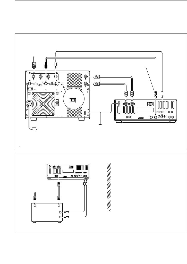
2 INSTALLATION AND CONNECTIONS
■ Linear amplifier connections |
Use the [ANT1] connector when connecting a linear |
||
|
|
amplifier. |
|
CONNECTING THE IC-PW1/EURO |
|
||
To an |
Remote control cable (supplied with the IC-PW1/EURO) |
||
|
|
||
antenna ACC-1 |
ACC cable (supplied with the IC-PW1/EURO) |
||
|
|
Be sure to connect the cable |
|
ANT |
REMOTE |
to the 7-pin ACC(2) jack. |
|
Coaxial cable |
|||
|
INPUT1 |
||
|
(supplied with the IC-PW1/EURO) |
||
|
INPUT2 |
|
Connect |
|
|
|
Coaxial cable |
[INPUT2] |
|
|
|
if necessary |
|
|
|
|
(optional) |
|
|
|
|
|
|
|
EXCITER |
ANT2 |
ANT1 ACC(2) |
REMOTE |
|
1 |
1&2 |
GND |
|
|
|
|
|
|
|
GND
IC-PW1/EURO
AC outlet |
|
|
Ground |
(Non-European versions: 100–120/220–240 V |
|||
European version |
: 230 V) |
||
Transceiver
 Turn OFF the transceiver’s antenna tuner while tuning the IC-PW1/EURO’s tuner.
CONNECTING A NON-ICOM LINEAR AMPLIFIER
Transceiver
|
ANT1 |
ALC SEND |
|
50 Ω coaxial |
|
To an |
cable |
|
antenna |
|
|
RF OUTPUT |
RF INPUT |
|
|
ALC |
|
|
SEND |
|
 R WARNING:
Set the transceiver output power and linear amplifier
 ALC output level referring to the linear amplifier in-
 struction manual.
 The ALC input level must be in the range 0 V to –4 V,
and the transceiver does not accept positive voltage.
 Non-matched ALC and RF power settings could cause a fire or ruin the linear amplifier.
 The specifications for the SEND relay are 16 V DC
0.5 A. If this level is exceeded, a large external relay  must be used.
Non-Icom linear amplifier
17
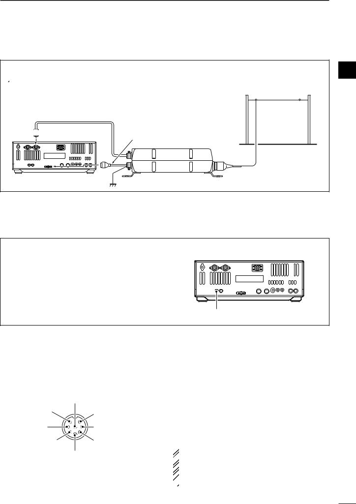
INSTALLATION AND CONNECTIONS |
2 |
■ External antenna tuner connection
CONNECTING THE AH-4/AH-3 |
2 |
|
 The AH-4 or AH-3 must be connected to [ANT1].
Long wire or optional AH-2b
Coaxial cable (from the AH-4 or AH-3)
ANT1 

Control cable
Transceiver |
AH-4 or AH-3 |
|
Ground |
■ Transverter jack information
When 2 to 13.8 V is applied to pin 6 of [ACC(2)], the [XVERT] jack is activated for transverter operation and the antenna connectors do not receive or transmit any signals. (p. 20)
While receiving, the [XVERT] jack can be activated as an input terminal from an external transverter.
While transmitting, the [XVERT] jack outputs signals of the displayed frequency at –20 dBm (22 mV) as signals for the external transverter.
Transverter jack
■ Microphone connector information
(Front panel view)
|
i Main readout AF output |
|
(varies with [AF]/[BAL]) |
q Microphone input |
u GND |
|
(Microphone ground) |
w +8 V DC output |
y GND (PTT ground) |
e Frequency up/down |
t PTT |
|
r Main readout squelch switch |
[MIC] |
FUNCTION |
DESCRIPTION |
|
Pin No. |
|||
|
|
||
w |
+8 V DC output |
Max. 10 mA |
|
|
|
|
|
|
Frequency up |
Ground |
|
e |
|
|
|
Frequency down |
Ground through 470 Ω |
||
|
|||
|
|
|
|
r |
Squelch open |
“Low” level |
|
|
|
||
Squelch closed |
“High” level |
||
|
|||
|
|
|
 CAUTION: DO NOT short pin 2 to ground as this
 can damage the internal 8 V regulator.
 NOTE: DC voltage is applied to pin 1 for micro-
 phone operation. Take care when using a non-Icom
  microphone.
18
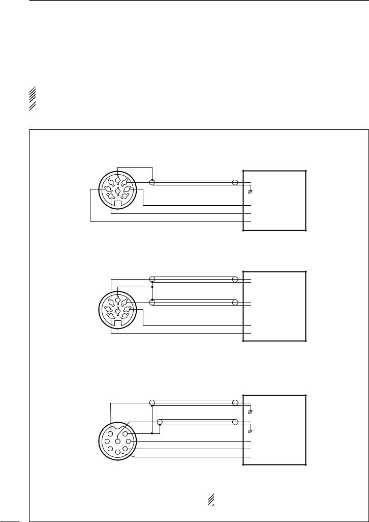
2 INSTALLATION AND CONNECTIONS
■ FSK and AFSK (SSTV) connections
To connect a terminal unit, TNC or scan converter, refer to the diagram below.
 For RTTY operation:
Narrow filter settings may not pass RTTY signals.
 Be sure to select the appropriate IF filter settings
  corresponding to the signal width. (p. 61)
FSK (RTTY) connection
Use RTTY mode for
operation |
|
|
Terminal unit (TU) or |
|
|
Terminal Node Controller (TNC) |
|
|
|
|
|
4 |
2 |
5 |
AF input |
1 |
8 |
3 |
Ground (GND) |
6 |
|
7 |
|
|
|
|
PTT |
|
|
|
SQUELCH input* |
|
|
|
RTTY keying |
[ACC(1)] socket |
|
||
(Rear panel view) |
* Connect the SQUELCH line when required. |
||
AFSK and SSTV connections
Terminal Node Controller (TNC)
Use SSB or FM mode for operation
4 |
2 |
5 |
|
|
|||
1 |
8 |
3 |
|
6 |
7 |
||
|
[ACC(1)] socket
or Scan converter
AFSK output
 Ground (GND)
AF input
 Ground (GND)
PTT
SQUELCH input*
(Rear panel view) |
* Connect the SQUELCH line when required. |
AFSK and SSTV connections via microphone connector
Terminal Node Controller (TNC)
Use SSB or FM mode for operation
|
1 |
7 |
2 |
8 |
6 |
|
3 |
5 |
|
4 |
|
[MIC] connector
(Front panel view)
or Scan converter
AFSK output
AF input
Ground (GND)
PTT
SQUELCH input*
* Connect the SQUELCH line when required.
 When connected to the [MIC] connector, [MIC
 GAIN] and [AF] control adjustment is required.
19

INSTALLATION AND CONNECTIONS |
2 |
■ Accessory connector information
ACC (1) |
PIN No. |
NAME |
DESCRIPTION |
SPECIFICATIONS |
|
|
||
|
2 |
|||||||
|
|
|
|
|
“High” level |
: More than 2.4 V |
|
|
|
|
1 |
RTTY |
Controls RTTY keying |
“Low” level |
: Less than 0.6 V |
|
|
|
|
|
|
|||||
|
|
|
|
|
Output current |
: Less than 2 mA |
|
|
|
|
|
|
|
|
|
|
|
|
|
2 |
GND |
Connects to ground. |
Connected in parallel with ACC(2) pin 2. |
|
|
|
|
|
|
|
|
|
|
|
|
|
|
|
|
Input/output pin. |
Ground level |
: –0.5 V to 0.8 V |
|
|
|
|
|
|
Output current |
: Less than 20 mA |
|
|
|
|
|
3 |
SEND |
Goes to ground when transmitting. |
|
|
||
|
|
Input current (Tx) |
: Less than 200 mA |
|
|
|||
|
|
|
|
When grounded, transmits. |
|
|
||
|
|
|
|
Connected in parallel with ACC(2) pin 3. |
|
|
||
2 |
|
|
|
|
|
|
||
5 |
|
|
|
|
|
|
|
|
|
|
|
|
|
|
|
||
4 |
4 |
MOD |
Modulator input. |
Input impedance |
: 10 kΩ |
|
|
|
1 8 |
3 |
|
|
|||||
|
|
Connects to a modulator. |
Input level |
: Approx. 100 mV rms |
|
|
||
6 |
7 |
|
|
|
|
|
|
|
|
|
AF detector output. |
Output impedance |
: 4.7 kΩ |
|
|
||
|
|
|
|
|
|
|||
|
|
5 |
AF |
Fixed, regardless of [AF] position |
|
|
||
|
|
Output level |
: 100–300 mV rms |
|
|
|||
Rear panel view |
|
|
in default settings. (see notes below) |
|
|
|||
|
|
6 |
SQLS |
Squelch output. |
SQL open |
: Less than 0.3 V/5 mA |
|
|
|
|
|
|
Goes to ground when squelch opens. |
SQL closed |
: More than 6.0 V/100 µA |
|
|
|
|
7 |
13.8 V |
13.8 V output when power is ON. |
Output current |
: Max. 1 A |
|
|
|
|
Connected in parallel with ACC(2) pin 7. |
|
|
||||
|
|
|
|
|
|
|
||
|
|
|
|
|
|
|
|
|
|
|
|
|
|
Control voltage |
: –4 V to 0 V |
|
|
|
|
8 |
ALC |
ALC voltage input. |
Input impedance |
: More than 10 kΩ |
|
|
|
|
|
|
|
Connected in parallel with ACC(2) pin 5. |
|
|
|
|
|
|
|
|
|
|
||
|
|
|
|
|
|
|
||
ACC (2) |
PIN No. |
NAME |
DESCRIPTION |
SPECIFICATIONS |
|
|
||
|
|
1 |
8 V |
Regulated 8 V output. |
Output voltage |
: 8 V ±0.3 V |
|
|
|
|
Output current |
: Less than 10 mA |
|
|
|||
|
|
|
|
|
|
|
||
|
|
|
|
|
|
|
|
|
|
|
2 |
GND |
Same as ACC(1) pin 2. |
|
|
|
|
2 |
|
|
|
|
|
|
|
|
5 |
3 |
SEND |
Same as ACC(1) pin 3. |
|
|
|
||
4 |
|
|
|
|
|
|
|
|
1 |
3 |
4 |
BAND |
Band voltage output. |
Output voltage |
: 0 to 8.0 V |
|
|
6 |
7 |
|
|
|||||
|
|
(Varies with amateur band) |
|
|
|
|
||
|
|
5 |
ALC |
Same as ACC (1) pin 8. |
|
|
|
|
Rear panel view |
|
|
|
|
|
|
|
|
6 |
TRV |
Activates [XVERT] input/output |
Input impedance |
: More than 10 kΩ |
|
|
||
|
|
|
|
|||||
|
|
when “HIGH” voltage is applied. |
Input voltage |
: 2 to 13.8 V |
|
|
||
|
|
|
|
|
|
|||
|
|
|
|
|
|
|
|
|
|
|
7 |
13.8 V |
Same as ACC(1) pin 7. |
|
|
|
|
|
|
|
|
|
|
|
|
|
 If the CW side tone level limit or beep level limit is in
use, the CW side tone or beep tone decreases from
 the fixed level when the [AF] control is rotated
  above a specified level, respectively. (p. 96)
20
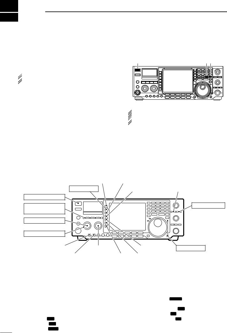
3 BASIC OPERATION
■ When first applying power (CPU resetting)
Before first applying power, make sure all connections required for your system are complete by referring to Section 2. Then, reset the transceiver using the following procedure.
 Resetting CLEARS all programmed contents in
  memory channels and returns programmed values
  in set mode to default values.
q Make sure the transceiver power is OFF.
wWhile pushing [M-CL] and [(F-INP)ENT], push [POWER] to turn power ON.
•The internal CPU is reset.
•A/D convertor calibration of the DSP unit starts and it takes 10 sec.
•The transceiver displays its initial VFO frequencies when resetting is complete.
eCorrect the set mode settings after resetting, if desired.
[POWER] |
[F-INP] [M-CL] |
 Under cooler temperatures, the LCD may appear
dark and unstable after turning power ON. This is
 normal and does not indicate any equipment mal-
  function.
■ Initial settings
After resetting the transceiver, set controls and |
|
|
|
|||
switches as shown in the figure below. |
|
CW |
: Max. clockwise |
|||
|
|
|
|
|
CCW |
: Max. counterclockwise |
|
|
|
|
|
|
|
|
[ANT]: 1 |
|
|
[P.AMP]: 1 |
|
|
|
|
|
|
|
|
|
[METER]: Po
[POWER]: OFF
[TUNER], [MONITOR], |
[NB], [NR]: OFF |
[AF]: Max. CCW |
[ATT]: OFF |
|
[PBT CLR]: OFF |
[NOTCH]: OFF
[RF/SQL]: 12 o’clock
[MIC GAIN]: 10–12 o’clock |
|
|
[BAL]: Center |
|
|
|
[AGC]: MID*1 |
|
||
|
|
|
|
|
|
|
|
|
|
|
|
[RF POWER]: Max. CW |
|
|
[COMP]*2: OFF WIDE; |
|
[VOX],*2 [BK-IN],*2 |
|
|||
|
|
|
|
|
[1/4],*2 [TONE]*2: OFF |
|
[RTTY FIL]*2: OFF |
|
||
Turn power ON, then check the display. If any of the following indicators appear, turn them OFF as follows:
[LOCK]: OFF
*1 FAST in FM mode.
*2 Appears in some modes.
•Quick tuning step indicator “▼” : Push [TS]. |
•Dualwatch indicator “ DUAL-W ” |
: Push |
|
•1 Hz frequency readout |
: Push [TS] for 2 sec. |
|
[DUALWATCH]. |
|
(while quick tuning |
• Twin peak filter indicator “ TPF ”: Push [RTTY FIL]. |
|
|
step is OFF) |
•Auto notch indicator “ A N ” |
: Push [NOTCH]. |
•RIT indicator “ RIT ” |
: Push [RIT]. |
•Manual notch indicator “ M N ” |
: Push [NOTCH]. |
• ∂TX indicator “ ∂TX ” |
: Push [∂TX]. |
|
|
•Split indicator “ SPLIT ” |
: Push [SPLIT]. |
|
|
21
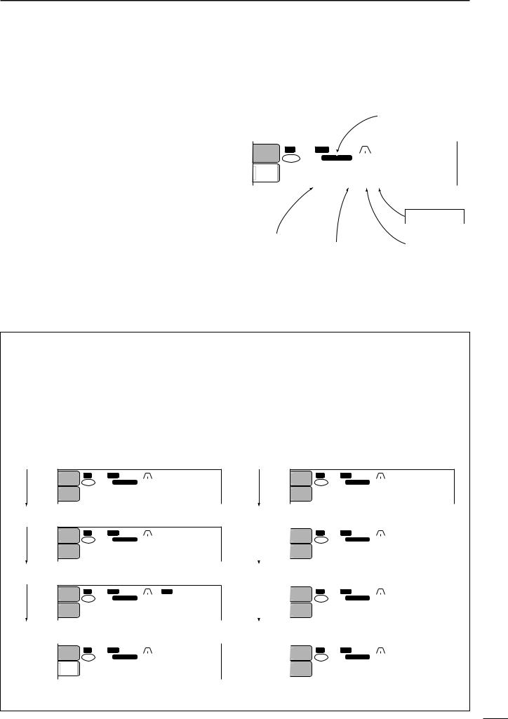
■ VFO description
VFO is an abbreviation of Variable Frequency Oscillator, and traditionally refers to an oscillator.
The transceiver’s VFO is somewhat different. The VFO of the IC-756PROIII acts like a computer’s window and can show one frequency and one operating mode.
You can call up a desired frequency to the VFO with the keypad, memo pad-read switch (see p. 82) or the memory transfer function (see p. 80). You can also change the frequency with the tuning dial and select the operating mode with the mode switches.
During dualwatch or split frequency operation, the sub VFO is functional (non-outline, non-spotted, larger frequency characters). While pushing [XFC] during split frequency operation, you can change the transmit readout frequency with the keypad, memo pad-read switch or the memory transfer function.
BASIC OPERATION |
3 |
|
|
|
|
|
|
|
|
|
MODE |
|
|
|
|
|
|
|
|
Select |
|
|
SWITCHES |
|
3 |
||
|
|
|
|
|
|
|
|
|
|
|||
|
|
|
|
|
|
|
|
|
|
|
|
|
|
|
|
|
|
|
|
|
|
|
|
|
|
|
|
|
|
|
|
|
|
|
|
|
|
|
|
ANT |
BW 2.4k SFT |
|
|
qw:pp |
|
||||||
|
|
|
|
|||||||||
|
1 |
|
|
|
|
|
|
|
12:00 |
|
|
|
|
TX VFO USB |
FIL2 |
|
|
||||||||
|
|
|
|
|||||||||
|
|
|
|
|
|
|||||||
|
METER |
|
qr.qpp.pp |
|
||||||||
|
Po |
|
|
|
|
|
|
|
|
|
|
|
121.076.50 CW
Change
Transfer
|
Transfer |
Transfer |
TUNING DIAL |
||
|
|
|
|
||
|
|
|
|
|
|
KEYPAD |
|
|
|
|
MEMORY |
(BAND KEY) |
|
MEMO PAD |
|
CHANNEL |
|
21.295 MHz |
|
28.025 MHz |
7.001 MHz |
||
•Differences between VFO mode and memory mode
VFO MODE
VFO shows a frequency and operating mode. If the frequency or operating mode is changed, the VFO automatically memorizes the new frequency or new operating mode.
When a VFO is selected from another band or memory mode, the frequency and operating mode last used for that VFO appear.
[EXAMPLE]
VFO is selected.
|
ANT |
BW 2.4k SFT |
0 |
|
|
|
qw:pp |
||
|
1 |
|
|
|
|
|
|
|
12:00 |
TX VFO |
USB |
|
FIL2 |
||||||
|
|
|
|||||||
|
|
|
|
||||||
|
METER |
qr.qpp.pp |
|
Po |
1 21.076.50 CW |
|
|
The frequency is changed.
|
ANT |
BW 2.4k SFT |
0 |
|
|
|
qw:pp |
||
|
1 |
|
|
|
|
|
|
|
12:00 |
TX VFO |
USB |
|
FIL2 |
||||||
|
|
|
|||||||
|
|
|
|
||||||
|
METER |
qr.qwe.pp |
|
Po |
1 21.076.50 CW |
|
|
Memory mode is selected.
|
ANT |
BW |
500 SFT |
0 |
|
|
BPF qw:pp |
|||
|
1 |
|
|
|
|
|
|
|
|
|
TX |
1 |
|
CW |
12:00 |
||||||
|
|
|
|
FIL2 |
||||||
|
|
METER |
|
wq.puy.tp |
|||||||
|
|
Po |
|
VFO 14.123.00 |
USB |
||||||
|
|
|
|
||||||||
|
|
|
|
||||||||
VFO is selected again. |
|
||||||||||
|
|
|
|
|
|||||||
|
|
|
|
|
|
|
|
|
|
qw:pp |
|
|
|
ANT |
BW 2.4k SFT 0 |
||||||||
|
|
||||||||||
|
|
1 |
|
|
|
|
|
|
|
12:00 |
|
TX VFO USB FIL2 |
|||||||||||
|
|
|
|
||||||||
|
|
METER |
|
qr.qwe.pp |
|||||||
|
|
Po |
|
|
|
|
|
|
|
|
|
121.076.50 CW
Changed frequency (14.123 MHz) appears.
MEMORY MODE (pgs. 77–81)
Each memory channel shows a frequency and operating mode like a VFO. Even if the frequency or mode is changed, the memory channel does not memorize the new frequency or operating mode.
When the memory channel is selected from another memory channel or VFO mode, the memorized frequency and operating mode appear.
[EXAMPLE]
Memory channel 1 is selected.
|
ANT |
BW 2.4k SFT |
0 |
|
|
|
qw:pp |
||
|
1 |
|
|
|
|
|
|
|
12:00 |
|
TX 1 |
USB |
|
FIL2 |
|||||
|
|
|
|||||||
|
|
|
|
||||||
|
|
|
METER |
|
qr.qpp.pp |
||||||
|
|
|
Po |
|
VFO 14.100.00 |
USB |
|||||
|
|
|
|
|
|||||||
The frequency is changed. |
|
|
|
|
|||||||
|
|
|
|
|
|
|
|
|
|
|
|
|
|
|
ANT |
BW 2.4k SFT 0 |
|
|
|
qw:pp |
|||
|
|
|
1 |
|
|
|
|
|
|
|
12:00 |
|
|
|
TX 1 USB |
|
FIL2 |
||||||
|
|
|
|
|
|||||||
|
|
|
|
|
|
||||||
|
|
|
|
|
qr.qwe.pp |
||||||
|
|
|
METER |
|
|||||||
|
|
|
|||||||||
|
|
|
Po |
|
VFO 14.100.00 USB |
||||||
|
|
|
|
|
|||||||
Another memory channel is selected. |
|
||||||||||
|
|
|
|
|
|
|
|
|
|
|
|
|
|
|
ANT |
BW 2.4k SFT 0 |
|
|
|
qw:pp |
|||
|
|
|
1 |
|
|
|
|
|
|
|
12:00 |
|
|
|
TX 12 USB |
|
FIL2 |
||||||
|
|
|
|
|
|||||||
|
|
|
|
|
|
||||||
|
|
|
|
|
wq.wrt.pp |
||||||
|
|
|
METER |
|
|||||||
|
|
|
|||||||||
|
|
|
Po |
|
VFO 14.100.00 USB |
||||||
|
|
|
|
|
|||||||
Memory channel 1 is selected again. |
|
||||||||||
|
|
|
|
|
|
|
|
|
|
|
|
|
|
|
ANT |
BW 2.4k SFT 0 |
|
|
|
qw:pp |
|||
|
|
|
1 |
|
|
|
|
|
|
|
12:00 |
|
|
|
TX 1 USB |
|
FIL2 |
||||||
|
|
|
|
|
|
||||||
|
|
|
|
|
qr.qpp.pp |
||||||
|
|
|
METER |
|
|||||||
|
|
|
|||||||||
|
|
|
Po |
|
VFO 14.100.00 |
USB |
|||||
|
|
|
|
|
|||||||
|
|
|
|
|
|
|
|
|
|
|
|
Changed frequency (14.123 MHz) does not appear and memorized frequency (14.100 MHz) appears instead.
22
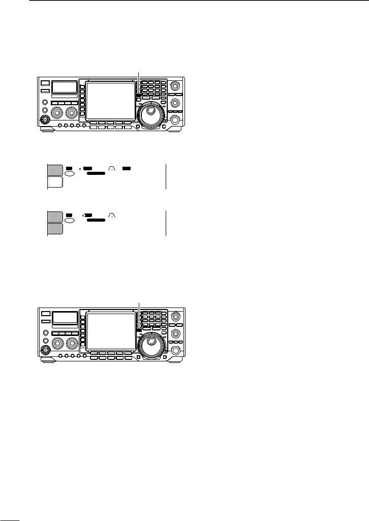
3 BASIC OPERATION
■ Selecting VFO/memory mode
[VFO/MEMO]
Push [VFO/MEMO] to switch between VFO and memory modes.
• “VFO” appears when VFO mode, or the selected memory channel number appears when memory mode is selected beside the frequency readout.
•Pushing [VFO/MEMO] for 1 sec. transfers the contents of the selected memory channel to VFO mode. (p. 80)
“VFO” indicator
|
|
|
|
|
|
|
|
|
|
|
|
|
|
|
|
|
|
|
|
|
|
ANT |
BW 5 |
|
|
SFT |
0 |
|
|
BPF |
qw:pp |
|
1 |
|
|
|
|
|
|
|
|
|
12:00 |
TX |
VFO |
CW |
|
FIL2 |
||||||
|
|
|
||||||||
METER qr.qot.pp
Po
114.100.00 USB
Memory channel number
|
|
|
|
|
|
|
|
|
|
|
|
|
|
|
|
|
|
|
|
|
|
ANT |
BW 2. |
|
|
FT |
0 |
|
|
qw:pp |
||
1 |
|
|
|
|
|
|
|
|
|
|
TX |
1 |
|
USB |
12:00 |
||||||
|
|
|
FIL2 |
|||||||
METER |
qr.qpp.pp |
Po |
VFO 14.195.00 CW |
|
|
|
■ Main/Sub band selection
[MAIN/SUB]
Push [MAIN/SUB] to select access to the main or sub readout.
•The sub readout frequency is displayed in outline or mesh font. The sub readout functions only during split oeration or dualwatch.
23
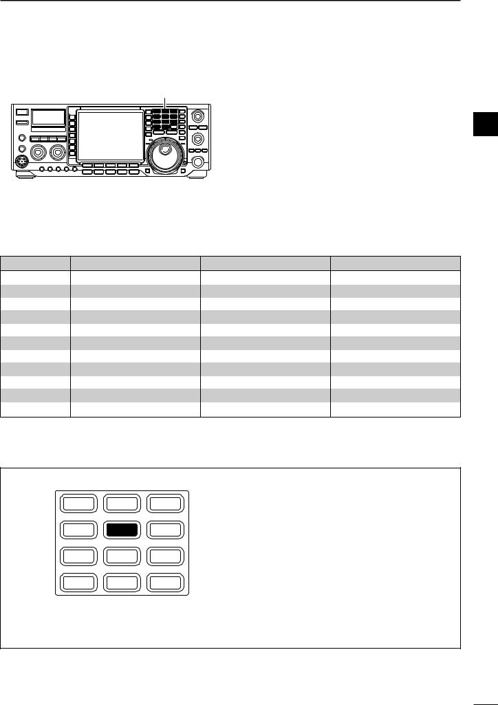
BASIC OPERATION |
3 |
■ Selecting an operating band
|
Band keys |
The triple band stacking register provides 3 memories |
|
|
in one band. 3 sets of a frequency and operating mode |
||
|
|
||
|
|
on each band are automatically stored when used. |
|
|
|
If a band key is pushed once, the frequency and oper- 3 |
|
|
|
ating mode last used are called up. When the key is |
|
|
|
pushed again, another stored frequency and operating |
|
|
|
mode are called up. |
|
|
|
This function is convenient when you operate 3 oper- |
|
|
|
ating modes on one band. For example, one register |
|
|
|
is used for a CW frequency, another for an SSB fre- |
|
|
|
quency and the other one for an RTTY frequency. |
|
|
|
See the table below for a list of the band available and |
|
|
|
the default settings for each band. |
|
BAND |
REGISTER 1 |
REGISTER 2 |
REGISTER 3 |
1.8 MHz |
1.900000 MHz CW |
1.910000 MHz CW |
1.915000 MHz CW |
3.5 MHz |
3.550000 MHz LSB |
3.560000 MHz LSB |
3.580000 MHz LSB |
7 MHz |
7.050000 MHz LSB |
7.060000 MHz LSB |
7.020000 MHz CW |
10 MHz |
10.120000 MHz CW |
10.130000 MHz CW |
10.140000 MHz CW |
14 MHz |
14.100000 MHz USB |
14.200000 MHz USB |
14.050000 MHz CW |
18 MHz |
18.100000 MHz USB |
18.130000 MHz USB |
18.150000 MHz USB |
21 MHz |
21.200000 MHz USB |
21.300000 MHz USB |
21.050000 MHz CW |
24 MHz |
24.950000 MHz USB |
24.980000 MHz USB |
24.900000 MHz CW |
28 MHz |
28.500000 MHz USB |
29.500000 MHz USB |
28.100000 MHz CW |
50 MHz |
50.100000 MHz USB |
50.200000 MHz USB |
51.000000 MHz FM |
General |
15.000000 MHz USB |
15.100000 MHz USB |
15.200000 MHz USB |
DUsing the band stacking registers
[Example]: 14 MHz band
1.8 1 3.5 2 7 3
10 4 14 5 18 6
21 7 24 8 28 9
GENE • |
50 0 |
F-INPENT |
qPush [(14)5], then select a frequency and an operating mode.
•Frequency and operating mode are memorized in the first band stacking register.
wPush [(14)5] again, then select another frequency and operating mode.
•This frequency and operating mode are memorized in the second band stacking register.
ePush [(14)5] again, then select another frequency and operating mode.
•This frequency and operating mode are memorized in the third band stacking register.
•When a fourth frequency and operating mode are selected on a band, the first register set in step q, is over written.
24
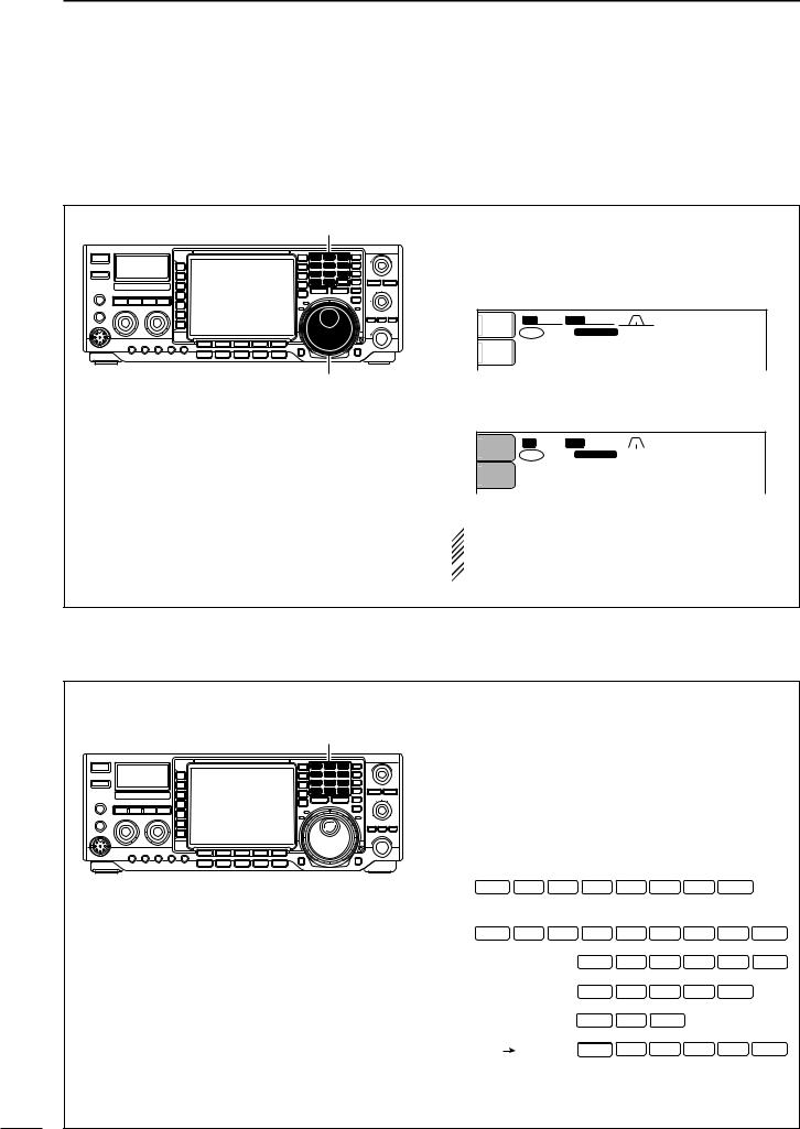
3 BASIC OPERATION
■ Frequency setting
The transceiver has several tuning methods for convenient frequency tuning.
DTuning with the tuning dial
Band keys |
q Push the desired band key on the keypad 1–3 |
||||
times. |
|
|
|
|
|
|
|
|
|
|
|
|
• 3 different frequencies can be selected on each band |
||||
|
with the band key. (See previous page “Using the band |
||||
|
stacking register.”) |
|
|
|
|
|
ANT |
BW 2.4k SFT |
0 |
|
qw:pp |
|
1 |
TX VFO |
USB |
|
12:00 |
|
|
FIL2 |
|
||
|
METER |
wq.wpp.pp |
|||
|
Po |
|
|
|
CW |
|
|
1 |
21.076.50 |
||
Tuning dial
w Rotate the tuning dial to set the desired frequency.
|
ANT |
BW 2.4k SFT |
0 |
|
|
qw:pp |
|||
|
1 |
|
|
|
|
|
|
|
|
|
TX VFO |
USB |
12:00 |
||||||
|
|
|
FIL2 |
||||||
|
METER |
wq.wot.pp |
|
Po |
1 21.076.50 CW |
|
|
|
|
|
 If the dial lock function is activated, the lock indica-
tor lights, and the tuning dial does not function. In
 this case, push [LOCK/SPEECH] to deactivate the
  lock function. (p. 65)
DDirect frequency entry with the keypad
The transceiver has a keypad for direct frequency entry as described right.
Keypad
qPush [(F-INP)ENT].
•“  ” appears.
wInput the desired frequency.
•Push [(GENE)•] to input “ • (decimal point)” between the MHz units and kHz units.
ePush [(F-INP)ENT] to set the input frequency.
•To cancel the input, push [MAIN/SUB] instead of
[(F-INP)ENT].
[EXAMPLES]
14.025 MHz
F-INPENT |
1 |
4 |
• |
0 |
2 |
5 |
F-INPENT |
18.0725 MHz
F-INPENT |
1 |
8 |
• |
0 |
7 |
2 |
5 |
F-INPENT |
||
706 kHz |
|
|
F-INPENT |
• |
7 |
0 |
6 |
F-INPENT |
||
5.100 MHz |
|
F-INPENT |
5 |
• |
1 |
F-INPENT |
|
|
||
7.000 MHz |
|
F-INP |
ENT |
7 |
F-INP |
ENT |
|
|
|
|
|
|
|
F-INP |
|
|
|
|
|
||
21.280 |
21.245 |
F-INP |
|
• |
2 |
4 |
5 |
F-INP |
ENT |
|
F-INPENT |
|
|||||||||
25
 Loading...