


INSTRUCTION MANUAL
VHF TRANSCEIVER
iF15/S
UHF TRANSCEIVER
iF25/S

FOREWORD
READ ALL INSTRUCTIONS carefully and completely before using the transceiver.
SAVE THIS INSTRUCTION MANUAL— This instruction manual contains important operating instructions for the IC-F15/
F15S VHF TRANSCEIVER and IC-F25/F25S UHF TRANSCEIVER.
EXPLICIT DEFINITIONS
WORD |
DEFINITION |
RWARNING
Personal injury, fire hazard or electric shock may occur.
CAUTION Equipment damage may occur.
NOTE
If disregarded, inconvenience only. No risk of personal injury, fire or electric shock.
OPERATING NOTES
•When transmitting with a portable radio, hold the radio in a vertical position with its microphone 5 to 10 centimeters away from your mouth. Keep the antenna at least 2.5 centimeters from your head and body.
•If you wear a portable two-way radio on your body, ensure that the antenna is at least 2.5 centimeters from your body when transmitting.
i

PRECAUTION
R WARNING! NEVER hold the transceiver so that the antenna is very close to, or touching exposed parts of the body, especially the face or eyes, while transmitting. The transceiver will perform best if the microphone is 5 to 10 cm away from the lips and the transceiver is vertical.
R WARNING! NEVER operate the transceiver with a headset or other audio accessories at high volume levels.
CAUTION! NEVER short the terminals of the battery pack.
NEVER connect the transceiver to a power source other than the BP-230, BP-231 or BP-232. Such a connection will ruin the transceiver.
DO NOT push the PTT when not actually desiring to transmit.
AVOID using or placing the transceiver in direct sunlight or in areas with temperatures below –25°C or above +55°C.
DO NOT modify the transceiver for any reason.
MAKE SURE the flexible antenna and battery pack are securely attached to the transceiver, and that the antenna and battery pack are dry before attachment. Exposing the inside of the transceiver to water will result in serious damage to the transceiver.
The use of non-Icom battery packs/chargers may impair transceiver performance and invalidate the warranty.
Icom, Icom Inc. and the 
 logo are registered trademarks of Icom Incorporated (Japan) in the United States, the United Kingdom, Germany, France, Spain, Russia and/or other countries.
ii

TABLE OF CONTENTS
FOREWORD ……………………………………………………………… i EXPLICIT DEFINITIONS ………………………………………………… i OPERATING NOTES ……………………………………………………… i PRECAUTION …………………………………………………………… ii TABLE OF CONTENTS ………………………………………………… iii
1 ACCESSORIES ……………………………………………………… 1–5
‘Supplied accessories………………………………………………… 1
‘Accessory attachments ……………………………………………… 2
2 PANEL DESCRIPTION …………………………………………… 6–11
‘Front, top and side panels ………………………………………… 6
‘LED indicator ………………………………………………………… 8
‘Programmable function keys ……………………………………… 9
3 CONVENTIONAL OPERATION ………………………………… 12–18
‘Turning power ON ………………………………………………… 12
‘Channel selection ………………………………………………… 12
‘Call procedure ……………………………………………………… 13
‘ Receiving and transmitting ……………………………………… 14 ‘ Scrambler function ………………………………………………… 16 ‘ Setting the squelch level ………………………………………… 16
‘Man Down Emergency Call ……………………………………… 17
4 OPTIONAL UNIT INSTALLATION……………………………… 18–19
‘Optional unit installation …………………………………………… 18
‘Scrambler unit installation ………………………………………… 19
5 BATTERY CHARGING ………………………………………… 20–25
‘Battery charging …………………………………………………… 20
‘Caution ……………………………………………………………… 21
‘Optional battery chargers ………………………………………… 22
6 SWIVEL BELT CLIP……………………………………………… 26–29
‘MB-93 contents …………………………………………………… 26
‘To attach …………………………………………………………… 26
‘To detach …………………………………………………………… 28
7 OPTIONS ………………………………………………………… 30–31
8 DOC………………………………………………………………… 32–33
iii
ACCESSORIES |
1 |
||
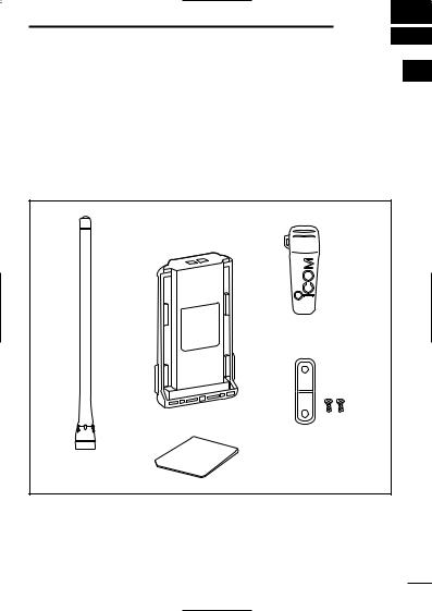
■ Supplied accessories |
|
1 |
|
The following accessories are supplied: |
|
Qty. |
|
q Flexible antenna . . . . . . . . . . . . . |
. . . . . . . . . . . . . . . |
. . . . |
. . . .1 |
w Battery pack . . . . . . . . . . . . . . . . |
. . . . . . . . . . . . . . . |
. . . . |
. . . .1 |
e Belt clip . . . . . . . . . . . . . . . . . . . . . |
. . . . . . . . . . . . . . |
. . . . |
. . . .1 |
r Unit cover (double-sided tape)* . . |
. . . . . . . . . . . . . . |
. . . . |
. . . .1 |
t Jack cover (with screws) . . . . . . . . |
. . . . . . . . . . . . . . |
. . . . |
.1 set |
* Use the unit cover as a spare. Ask your dealer for details. |
|
||
q |
w |
e |
|
t
r
1
1 ACCESSORIES
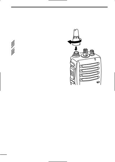
■ Accessory attachments
D Flexible antenna
Connect the supplied flexible antenna to the antenna connector.
 CAUTION:
• NEVER HOLD by the antenna  when carrying the transceiver.
• Transmitting without an antenna  may damage the transceiver.
2
ACCESSORIES 1
1
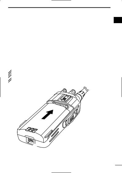
ï Battery pack
To attach the battery pack:
Slide the battery pack on the back of the transceiver in the direction of the arrow (q), then lock it with the battery release button.
•Slide the battery pack until the battery release button makes a ‘click’ sound.
To release the battery pack:
Push the battery release button in the direction of the arrow (w) as shown below. The battery pack is then released.
 NEVER release or attach the battery pack when the transceiver
is wet or soiled. This may result in water or dust getting into the
 transceiver/battery pack and may result in the transceiver being
  damaged.
q |
 w
w
3
1 ACCESSORIES
4

ACCESSORIES |
1 |
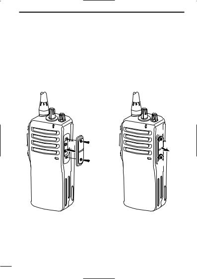
D Belt clip |
1 |
To attach the belt clip:
q Release the battery pack if it is attached.
wSlide the belt clip in the direction of the arrow until the belt clip is locked and makes a ‘click’ sound.
To detach the belt clip:
q Release the battery pack if it is attached.
wPinch the clip (q), and slide the belt clip in the direction of the arrow (w).
w
q
5
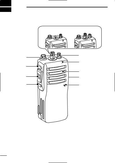
2 PANEL DESCRIPTION
■ Front, top and side panels
q IC-F15S/F25S |
IC-F15/F25 |
i |
w |
|
|
|
e |
u |
|
|
Speaker |
y |
r |
t |
Microphone |
q CHANNEL SW/SELECTOR
• IC-F15S/F25S: Toggle the channel switch to select the pre-pro- grammed channel 1 or 2.
• IC-F15/F25 : Rotate the channel selector to select the preprogrammed memory channels.
w VOLUME CONTROL [VOL]
Rotate to turn the power ON/OFF and adjust the audio level.
6
PANEL DESCRIPTION |
2 |
e LED INDICATOR (p. 8) |
2 |
Lights red while transmitting.
Lights green while receiving a signal, or when the squelch is open.
Lights/blinks orange when the matched 2/5-tone code is re-
ceived, according to the pre-programming.
r SPEAKER-MICROPHONE CONNECTOR [SP MIC]
Connects the optional speaker-microphone. (p. 31)
[SP MIC] jack cover
NOTE: Attach the [SP MIC] jack cover when the optional speak- er-microphone is not used. (p. 4)
t DEALER-PROGRAMMABLE KEY [Lower]
The desired function can be assigned by your dealer. (p. 9) y PTT SWITCH [PTT]
Push and hold to transmit; release to receive. u DEALER-PROGRAMMABLE KEY [Upper]
The desired function can be assigned by your dealer. (p. 9) i ANTENNA CONNECTOR
Connects the supplied antenna.
D Programmable key reference
Upper
Lower
7
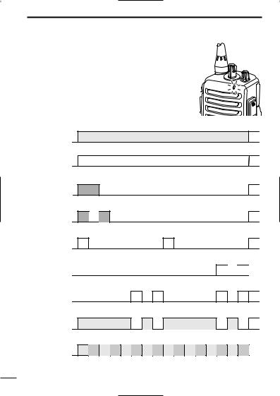
2 PANEL DESCRIPTION
‘ LED indicator
The LED indicator indicates several information as follows;
(Ref.; R=Red, G=Green, O=Orange)
• TX: Turns Red while transmitting a signal.
R
• RX: Turns Green while receiving a signal.
G
• Call LED (ON): When receiving a matched 2/5-tone.
O O
• Call LED (Blink): When receiving a matched 2/5-tone.
O 
 O
O
• Fast/Slow scan: Blinks while Fast/Slow scan is activated.
G |
G |
• Low BATT1: You should charge the battery. (blinks slowly)
G 
 G
G
• Low BATT2: You must charge the battery. (blinks fast)
G G |
G G |
• TX low BATT2: Low BATT2 was detected during TX mode.
R |
R |
R |
R |
• CH err: Non-programmed channel is selected.
R O R O R O R O R O R O R O R O 
8
 Loading...