


Gasoline containing up to 10% ethanol (E10) is acceptableforuseinthismachine. Theuseofanygasolineexceeding10%ethanol(E10)willvoidtheproductwarranty.
.
581 51 27-49
Operator’s Manual
Owner's Manual
YTH24K54 |
|
Please read the operator's manual carefully and make sure |
|
you understand the instructions before using the machine. |
English |
|

SAFETY RULES
Safe Operation Practices for Ride-On Mowers
DANGER: THIS CUTTING MACHINE IS CAPABLE OF AMPUTATING HANDS AND FEET AND THROWING OBJECTS. FAILURE TO OBSERVE THE FOLLOWING SAFETY INSTRUCTIONS COULD RESULT IN SERIOUS INJURY OR DEATH.
WARNING: In order to prevent accidental starting when setting up, transporting, adjusting or making repairs, always disconnect spark plug wire and place wire where it cannot contact spark plug.
WARNING: Do not coast down a hill in neutral, you may lose control of the tractor.
WARNING: Tow only the attachments that are recommended by and comply with specifications of the manufacturer of your tractor. Use common sense when towing. Operate only at the lowest possible speed when on a slope. Too heavy of a load, while on a slope, is dangerous. Tires can lose traction with the ground and cause you to lose control of your tractor.
 WARNING
Engineexhaust,someofitsconstituents,andcertain vehicle components contain or emit chemicals known to the State of California to cause cancer and birth defects or other reproductive harm.
 WARNING
Battery posts, terminals and related accessories containleadandleadcompounds,chemicalsknown to the State of California to cause cancer and birth defects or other reproductive harm. Wash hands after handling.
I. GENERAL OPERATION
•Read, understand, and follow all instructions on the machine and in the manual before starting.
•Do not put hands or feet near rotating parts or under the machine. Keep clear of the discharge opening at all times.
•Only allow responsible adults, who are familiar with the instructions, to operate the machine.
•Clear the area of objects such as rocks, toys, wire, etc., which could be picked up and thrown by the blades.
•Ensure the area is clear of bystanders before operating. Stop machine if anyone enters the area.
•Never carry passengers.
•Do not mow in reverse unless absolutely necessary. Always look down and behind before and while backing.
•Never direct discharged material toward anyone. Avoid discharging material against a wall or obstruction. Material may ricochet back toward the operator. Stop the blades when crossing gravel surfaces.
•Donotoperatemachinewithouttheentiregrasscatcher,discharge chute, or other safety devices in place and working.
•Slow down before turning.
•Never leave a running machine unattended. Always turn off blades, set parking brake, stop engine, and remove keys before dismounting.
•Disengage blades when not mowing. Shut off engine and wait for all parts to come to a complete stop before cleaning the machine, removing the grass catcher, or unclogging the discharge chute.
•Operate machine only in daylight or good artificial light.
•Do not operate the machine while under the influence of alcohol or drugs.
•Watchfortrafficwhenoperatingnearorcrossingroadways.
•Use extra care when loading or unloading the machine into a trailer or truck.
•Always wear eye protection when operating machine.
•Data indicates that operators, age 60 years and above, are involved in a large percentage of riding mower-related injuries. These operators should evaluate their ability to operate the riding mower safely enough to protect themselves and others from serious injury.
•Follow the manufacturer's recommendation for wheel weights or counterweights.
•Keep machine free of grass, leaves or other debris build-up which can touch hot exhaust / engine parts and burn. Do not allow the mower deck to plow leaves or other debris which can cause build-up to occur. Clean any oil or fuel spillage before operating or storing the machine. Allow machine to cool before storage.
II. SLOPE OPERATION
Slopes are a major factor related to loss of control and tipover accidents, which can result in severe injury or death. Operation on all slopes requires extra caution. If you cannot back up the slope or if you feel uneasy on it, do not mow it.
•Mow up and down slopes, not across.
•Watch for holes, ruts, bumps, rocks, or other hidden objects. Uneven terrain could overturn the machine. Tall grass can hide obstacles.
•Choose a low ground speed so that you will not have to stop or shift while on the slope.
•Do not mow on wet grass. Tires may lose traction.
Always keep the machine in gear when going down slopes. Do not shift to neutral and coast downhill.
•Avoid starting, stopping, or turning on a slope. If the tires lose traction, disengage the blades and proceed slowly straight down the slope.
•Keep all movement on the slopes slow and gradual. Do not make sudden changes in speed or direction, which could cause the machine to roll over.
•Use extra care while operating machine with grass catchers or other attachments; they can affect the stability of the machine. Do no use on steep slopes.
•Do not try to stabilize the machine by putting your foot on the ground.
•Do not mow near drop-offs, ditches, or embankments. The machine could suddenly roll over if a wheel is over the edge or if the edge caves in.
2

SAFETY RULES
Safe Operation Practices for Ride-On Mowers
III. CHILDREN
WARNING. CHILDRENCANBEINJUREDBY THIS EQUIPMENT. The American Academy of Pediatrics recommends that children be a minimum of 12 year of age before operating a pedestrian controlled lawn mower and a minimumof16yearsofagebeforeoperating a riding lawn mower.
Tragic accidents can occur if the operator is not alert to the presence of children. Children are often attracted to the machine and the mowing activity. Never assume that children will remain where you last saw them.
•Keep children out of the mowing area and in the watchful care of a responsible adult other than the operator.
•Be alert and turn machine off if a child enters the area.
•Before and while backing, look behind and down for small children.
•Never carry children, even with the blades shut off. They may fall off and be seriously injured or interfere with safe machine operation. Children who have been given rides in the past may suddenly appear in the mowing area for anotherrideandberunoverorbackedoverbythemachine.
•Never allow children to operate the machine.
•Use extra care when approaching blind corners, shrubs, trees, or other objects that may block your view of a child.
•If fuel is spilled on clothing, change clothing immediately.
•Never overfill fuel tank. Replace gas cap and tighten securely.
GENERAL SERVICE
•Never operate machine in a closed area.
•Keep all nuts and bolts tight to ensure the equipment is in safe working condition.
•Never tamper with safety devices. Check their proper operation regularly.
•Keep machine free of grass, leaves, or other debris buildup. Clean oil or fuel spillage and remove any fuel-soaked debris. Allow machine to cool before storing.
•If you strike a foreign object, stop and inspect the machine. Repair, if necessary, before restarting.
•Never make any adjustments or repairs with the engine running.
•Check grass catcher components and the discharge chute frequently and replace with manufacturer's recommended parts, when necessary.
•Mower blades are sharp. Wrap the blade or wear gloves, and use extra caution when servicing them.
•Check brake operation frequently. Adjust and service as required.
•Maintain or replace safety and instruction labels, as necessary.
IV. TOWING
•Tow only with a machine that has a hitch designed for towing. Do not attach towed equipment except at the hitch point.
•Follow the manufacturer's recommendation for weight limits for towed equipment and towing on slopes.
•Never allow children or others in or on towed equipment.
•On slopes, the weight of the towed equipment may cause loss of traction and loss of control.
•Travel slowly and allow extra distance to stop.
V. SERVICE
SAFE HANDLING OF GASOLINE
To avoid personal injury or property damage, use extreme care in handling gasoline. Gasoline is extremely flammable and the vapors are explosive.
•Extinguish all cigarettes, cigars, pipes, and other sources of ignition.
•Use only approved gasoline container.
•Never remove gas cap or add fuel with the engine running. Allow engine to cool before refueling.
•Never fuel the machine indoors.
•Never store the machine or fuel container where there is an open flame, spark, or pilot light such as on a water heater or other appliances.
•Never fill containers inside a vehicle or on a truck or trailer bed with plastic liner. Always place containers on the ground away from your vehicle when filling.
•Remove gas-powered equipment from the truck or trailer and refuel it on the ground. If this is not possible, then refuel such equipment with a portable container, rather than from a gasoline dispenser nozzle.
•Keep the nozzle in contact with the rim of the fuel tank or container opening at all times until fueling is complete. Do not use a nozzle lock-open device.
•Ensure the area is clear of bystanders before operating. Stop machine if anyone enters the area.
•Never carry passengers.
•Do not mow in reverse unless absolutely necessary. Always look down and behind before and while backing.
•Never carry children, even with the blades shut off. They may fall off and be seriously injured or interfere with safe machine operation. Children who have been given rides in the past may suddenly appear in the mowing area for another ride and be run over or backed over by the machine.
•Keep children out of the mowing area and in the watchful care of a responsible adult other than the operator.
•Be alert and turn machine off if a child enters the area.
•Before and while backing, look behind and down for small children.
•Mow up and down slopes (15° Max), not across.
•Choose a low ground speed so that you will not have to stop or shift while on the slope.
•Avoid starting, stopping, or turning on a slope. If the tires lose traction, disengage the blades and proceed slowly straight down the slope.
•If machine stops while going uphill, disengage blades, shift into reverse and back down slowly.
•Do not turn on slopes unless necessary, and then, turn slowly and gradually downhill, if possible.
•When loading or unloading this machine, do not exceed the maximum recommended operation angle of 15°.
3

PRODUCT SPECIFICATIONS
Gasoline Capacity |
3.0 Gallons/11,35 L |
|
and type: |
Unleaded Regular |
|
Oil Type (API: SG-SL): |
SAE 10W30 (above 32°F/0°C) |
|
|
SAE 5W30 (below 32°F/0°C) |
|
|
|
|
Oil Capacity: |
64 oz/1,96 L |
|
|
|
|
Spark Plug: |
Champion RC12YC |
|
|
(Gap: .030"/.76 mm) |
|
Ground Speed (Mph/Kph): |
Forward: |
0 - 5.2/ 0 - 8,4 |
|
Reverse: |
0 - 2.9/ 0 - 4,7 |
Charging System: |
15 AMPS @ 3600 RPM |
|
|
|
|
Battery: |
AMP/HR: |
28 |
|
MIN. CCA: |
230 |
|
Case Size: |
U1R |
Blade Bolt Torque: |
45-55 FT. LBS.(62-75 Nm) |
|
|
|
|
CONGRATULATIONS on your purchase of a new tractor. It has been designed, engineered and manufactured to give you the best possible dependability and performance.
Should you experience any problem you cannot easily remedy, please contact your nearest authorized service center/department. Wehavecompetent,well-trainedtechni- cians and the proper tools to service or repair this tractor.
Please read and retain this manual. The instructions will enable you to assemble and maintain your tractor properly. Always observe the “SAFETY RULES”.
CUSTOMER RESPONSIBILITIES
•Read and observe the safety rules.
•Follow a regular schedule in maintaining, caring for and using your tractor.
•Follow the instructions in the Maintenance and Storage sections of this manual.
•Wear proper Personal Protective Equipment (PPE) while operating this machine, including (at a minimum) sturdy footwear, eye protection, and hearing protection. Do not mow in shorts and/or open toed footwear.
•Always let someone know you are outside mowing.
WARNING: This tractor is equipped with an internal combustion engine and should not be used on or near any unimproved forest-covered, brush-covered or grasscovered land unless the engine’s exhaust system is equipped with a spark arrester meeting applicable local or state laws (if any). If a spark arrester is used, it should be maintained in effective working order by the operator.
A spark arrester for the muffler is available through your nearest authorized service center/department.
TABLE OF CONTENTS
SAFETY RULES ......................................................... |
2-3 |
PRODUCT SPECIFICATIONS....................................... |
4 |
CUSTOMER RESPONSIBILITIES................................. |
4 |
UNASSEMBLED PARTS............................................... |
5 |
ASSEMBLY................................................................. |
6-9 |
OPERATION ........................................................... |
10-16 |
MAINTENANCE SCHEDULE ...................................... |
17 |
MAINTENANCE..................................................... |
17-21 |
SERVICE AND ADJUSTMENTS............................ |
22-26 |
STORAGE.................................................................... |
27 |
TROUBLESHOOTING............................................ |
28-29 |
WARRANTY............................................................ |
30-33 |
ESPAÑOL .................................................................... |
35 |
4
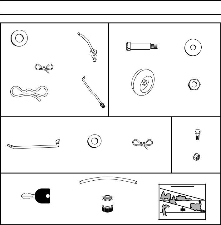
UNASSEMBLED PARTS
(5) 1-3/16 O.D. Washers
Mower
(2) Rear
Lift Link
Assemblies 


(1) Small
Retainer Springs |
|
|
(1) Front |
|
Lift Link |
(5) Large |
Assembly |
Retainer Springs |
|
Mower Front Wheel
(1) Shoulder Bolt
(1) 1-1/4 O.D.
Washer
(1) Wheel |
(1) 3/8-16 |
Locknut |
If Equipped |
Battery |
|
|
(2) Hex Bolts |
|
(1) Anti-Sway Bar |
(1) 3/4 O.D. |
(1) Small Retainer |
|
Washers |
Springs |
||
|
|||
|
|
(2) Nut Keps |
Keys |
Slope Sheet |
|
(1) Oil Drain Tube |
(2) Keys
(1) Quick Connect
5
ASSEMBLY
Your new tractor has been assembled at the factory with exception of those parts left unassembled for shipping purposes. To ensure safe and proper operation of your tractor all parts and hardware you assemble must be tightened securely. Use the correct tools as necessary to ensure proper tightness.
TOOLS REQUIRED FOR ASSEMBLY
A socket wrench set will make assembly easier. Standard wrench sizes are listed.
(2) |
7/16" wrenches |
Utility knife |
(1) |
1/2" wrench |
Tire pressure gauge |
(1) |
3/4" wrench |
Pliers |
(1) |
3/4" socket w/drive ratchet |
|
(1) |
9/16" wrench |
Flashlight |
When right or left hand is mentioned in this manual, it means when you are in the operating position (seated behind the steering wheel).
TOREMOVETRACTORFROMCARTON
UNPACK CARTON
•Remove all accessible loose parts and parts cartons from carton.
•Remove end panels and lay side panels flat.
•Remove mower and packing materials.
•Check for any additional loose parts or cartons and remove.
BEFORE REMOVING TRACTOR FROM SKID
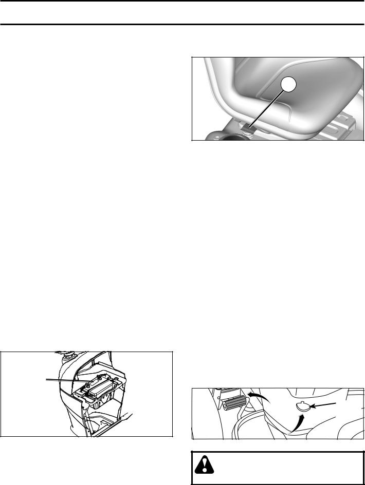
TO CHECK BATTERY (See Fig. 1)
•Lift hood to raised position.
NOTE: If this battery is put into service after month and year indicated on label (label is located between terminals) charge battery for minimum of one hour at 6-10 amps. (See "BATTERY" in Maintenance section of this manual for charging instructions).
•For battery and battery cable installation see "REPLACING BATTERY" in the "Service and Adjustments" section in this manual.
LABEL |
Fig. 1
ADJUST SEAT (See Fig. 2)
•Sit in seat.
•Lift up adjustment lever (A) and slide seat until a comfortable position is reached which allows you to press clutch/brake pedal all the way down.
• Release lever to lock seat in position. |
6 |
|
A
Fig. 2
NOTE: You may now roll your tractor off the skid. Follow the instructions below to remove the tractor from the skid.
 WARNING: Before starting, read, understand and follow all instructions in the Operation section of this manual. Be sure tractor is in a well-ventilated area. Be sure the area in front of tractor is clear of other people and objects.
TO ROLL TRACTOR OFF SKID (See Operation section for location and function of controls)
•Raise attachment lift lever to its highest position.
•Releaseparkingbrakebydepressingclutch/brakepedal.
•Place freewheel control in "transmission disengaged" position (See “TO TRANSPORT” in the Operation section of this manual).
•Roll tractor forward off skid.
•Remove banding holding the deflector shield up against tractor.
Continue with the instructions that follow.
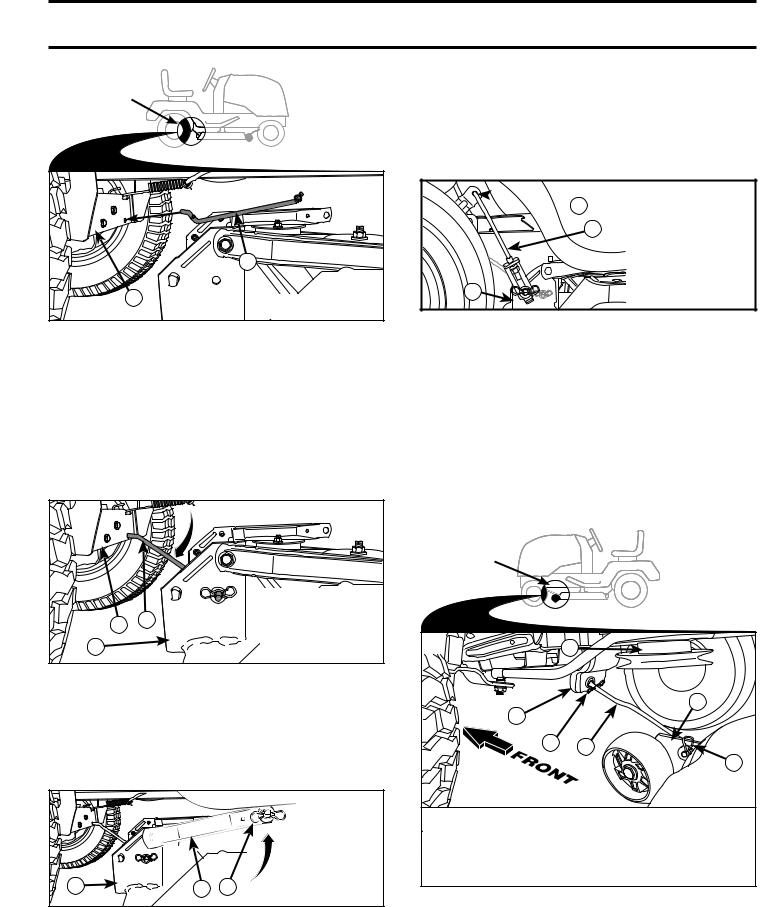
TO INSTALL MOWER AND DRIVE BELT (See Figs. 3 - 15)
1.SET PARKING BRAKE LEVER AND LOWER ATTACHMENT LIFT LEVER (See Fig. 3 and 4)
•Depress clutch/brake pedal all the way down and hold.
•Pull parking brake lever up and hold, release pressure from clutch/brake pedal, then release parking brake lever. Pedal should remain in brake position. Ensure parking brake will hold tractor secure.
PARKING
BRAKE
LEVER
Fig. 3
CAUTION: Lift lever is spring loaded. Have a tight grip on lift lever, lower it slowly and engage in lowest position. Lift lever is located on left side of fender.

ASSEMBLY
LIFT
LEVER
Fig. 4
2.ASSEMBLE FRONT GAUGE WHEEL (W) TO FRONT OF MOWER (See Fig. 5)
H |
W |
X |
Z |
Y |
H.FRONT MOWER BRACKET
W. FRONT GAUGE  WHEEL
WHEEL
X.SHOULDER BOLT
Y.1-1/4 O.D. WASHER
Z.3/8-16 LOCKNUT
Fig. 5
3.TURN STEERING WHEEL LEFT AND POSITION MOWER (See Fig. 6)
•Turn steering wheel to the left as far as it will go and position mower on right side of tractor with deflector shield (Q) to the right.
4. SLIDE MOWER UNDER TRACTOR (See Fig. 8)
•Bring belt forward and check belt for proper routing in all mower pulley grooves.
NOTE: Be sure mower side suspension arms (A) are pointing forward before sliding mower under tractor.
•Slide mower under tractor until it is centered under tractor.
|
|
Q |
|
A |
A. MOWER SIDE |
|
SUSPENSION |
|
|
|
|
|
|
ARMS |
|
|
Q. DEFLECTOR |
02965 |
|
SHIELD |
|
|
Fig. 8
5.INSTALL ANTI-SWAY BAR (S) (IF EQUIPPED) (See Fig. 9 - 11)
FRONT |
|
ANTI-SWAY BAR (S) |
|
|
Q |
TOWARDS |
TOWARDS |
|
|
||
|
|
TRANSAXLE |
MOWER DECK |
ENGINE |
|
|
|
|
|
90° END |
INTEGRATED WASHER END |
TRANSAXLE |
|
Fig. 9 |
|
|
|
|
Q. DEFLECTOR |
• From right side of mower, first insert 90° end of anti-sway |
02965 |
bar (S) into hole in transaxle bracket (T), located near |
|
BACK |
SHIELD |
left rear tire in front of transaxle. |
|
Fig. 6 |
NOTE: Flashlight may be helpful. |
|
|
|
M |
F |
|
A. MOWER SIDE SUSPENSION |
|
B |
|
|
||
|
|
|
|
ARMS |
|
|
|
|
W |
|
B. RETAINER SPRING |
L |
|
A |
|
C. REAR LIFT LINK(S) |
|
|
|
|
|||
K |
|
|
|
D. RIGHT SIDE REAR MOWER |
|
|
|
E |
|
BRACKET |
|
|
|
|
|
E. FRONT LIFT LINK ASSEMBLY |
|
|
|
|
|
|
|
|
|
|
|
|
F. FRONT SUSPENSION BRACKET |
|
|
|
|
|
H. FRONT MOWER BRACKET |
|
|
|
|
|
I. LEFT SIDE REAR MOWER |
|
|
|
|
H |
BRACKET |
C |
|
|
|
K. BELT TENSION ROD |
|
|
|
|
|
||
|
|
|
|
L. LOCKING BRACKET |
|
|
|
|
|
|
|
I |
|
|
|
|
M. ENGINE CLUTCH PULLEY |
C |
|
|
|
|
Q. DEFLECTOR SHIELD |
|
|
|
|
S. ANTI-SWAY BAR |
|
S |
|
|
|
|
|
|
D |
Q |
|
W. FRONT GAUGE WHEEL |
|
|
|
|
Fig. 7
7
ASSEMBLY
ANTI-SWAY BAR |
TRANSAXLE |
(S) LOCATION |
BRACKET (T) |
LOCATED
BETWEEN REAR
|
|
90°END |
INTO |
HOLE |
|
|
|
||
|
PLACE |
|
|
|
|
|
|
|
|
|
|
|
S |
|
T |
|
|
S. ANTI-SWAY BAR |
|
|
|
|
T. TRANSAXLE BRACKET |
|
Fig. 10
NOTE: Depending on model, bracket (T) may be different than shown but hole for anti-sway bar will be in same position/location.
•Pivot the integrated washer end of anti-sway bar (S) towards mower deck bracket on right side of mower. Insert integrated washer end of bar into hole in rear mower bracket (D). Move mower as needed to insert integrated washer end of bar into rear mower bracket (D).
•Secure with small washer and small retainer spring as shown.
|
|
D. RIGHT SIDE |
|
|
|
|
REAR MOWER |
|
T |
S |
BRACKET |
|
S. ANTI-SWAY BAR |
||
|
|
||
D |
|
T. |
TRANSAXLE |
|
|
BRACKET |
|
|
|
|
|
Fig. 11
6.ATTACH MOWER SIDE SUSPENSION ARMS (A) TO CHASSIS (See Fig. 12)
•Position front hole in side suspension arm (A) over pin on outside of tractor chassis and secure with large washer and large retainer spring (B).
•Repeat on opposite side of tractor.
|
|
|
A.MOWER SIDE |
|
|
|
|
SUSPENSION |
|
|
|
|
ARMS |
|
|
|
|
B. RETAINER |
|
|
|
|
SPRING |
|
|
|
|
D. RIGHT |
|
|
|
|
SIDE REAR |
|
D |
A |
B |
MOWER |
|
BRACKET |
||||
|
|
|
Fig. 12
7. ATTACH REAR LIFT LINKS (C) (See Fig. 13)
•Insert rod end of rear lift link (C) into hole (U) in tractor lift shaft suspension arm and pivot link down to mower.
•Lift rear corner of mower and position slot in link assembly over pin on rear mower bracket (D) and secure with large washer and large retainer spring.
•Repeat on opposite side of tractor.
 U
U
C
|
C. REAR LIFT LINK(S) |
|
|
D. RIGHT SIDE REAR |
|
D |
MOWER BRACKET |
|
U. HOLE |
||
|
Fig. 13
8 ATTACH FRONT LINK (E) (See Fig. 14)
•Turn steering wheel to position wheels straight forward.
•From front of tractor, insert rod end of front link (E) through front hole in tractor front suspension bracket (F).
•Move to left side of mower and and insert large retainer spring (G) through hole in front link (E) behind front suspension bracket (F).
•Insert other end of link (E) into hole in front mower bracket (H) and secure with washer and small retainer spring (J).
NOTE: Requires deck lifting.
FRONT LINK
LOCATION
M
H
F
G E
J
E.FRONT LIFT LINK ASSEMBLY
F.FRONT SUSPENSION BRACKET
G.LARGE RETAINER SPRING
H.FRONT MOWER BRACKET
J. SMALL RETAINER SPRING
M. ENGINE CLUTCH PULLEY
Fig. 14
8
ASSEMBLY
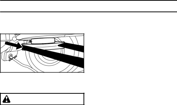
9INSTALL BELT ON ENGINE CLUTCH PULLEY (M) (See Fig. 7 & 15)
•Disengage belt tension rod (K) from locking bracket (L).
•Install belt onto engine clutch pulley (M).
M |
M.ENGINE |
CLUTCH PULLEY |
Fig. 15
IMPORTANT: Check belt for proper routing in all mower pulley grooves and under mandrel covers.
•Engage belt tension rod (K) on locking bracket (L).
CAUTION: Belt tension rod is spring loaded. Have a tight grip on rod and engage slowly.
•Raise attachment lift lever to highest position.
•If necessary, adjust gauge wheels before operating mower as shown in the Operation section of this manual.
MOWER DRIVE BELT INSTALLATION
Follow procedure described in “TO REPLACE MOWER BLADE DRIVE BELT ” in the "Service and Adjustments" section of this manual.
CHECK TIRE PRESSURE
The tires on your tractor were overinflated at the factory for shipping purposes. Correct tire pressure is important for best cutting performance.
•Reduce tire pressure to PSI shown on tires.
CHECK DECK LEVELNESS
For best cutting results, mower housing should be properly leveled. See “TO LEVEL MOWER HOUSING” in the Service and Adjustments section of this manual.
CHECK FOR PROPER POSITION OF ALL BELTS
See the figures that are shown for replacing motion and mower blade drive belts in the Service and Adjustments section of this manual. Verify that the belts are routed correctly.
CHECK BRAKE SYSTEM
After you learn how to operate your tractor, check to see that the brake is operating properly. See “TO CHECK BRAKE” in the Service and Adjustments section of this manual.
CHECKLIST
BEFORE YOU OPERATE YOUR NEW TRACTOR, WE WISH TO ASSURE THAT YOU RECEIVE THE BEST PERFORMANCE AND SATISFACTION FROM THIS QUALITY PRODUCT.
PLEASE REVIEW THE FOLLOWING CHECKLIST:
All assembly instructions have been completed.
No remaining loose parts in carton.
Battery is properly prepared and charged.
Seat is adjusted comfortably and tightened securely.
All tires are properly inflated. (For shipping purposes, the tires were overinflated at the factory).
Be sure mower deck is properly leveled side-to-side/ front-to-rear for best cutting results. (Tires must be properly inflated for leveling).
Check mower and drive belts. Be sure they are routed properly around pulleys and inside all belt keepers.
Check wiring. See that all connections are still secure and wires are properly clamped.
Before driving tractor, be sure freewheel control is in “transmission engaged” position (see “TO TRANSPORT” in the Operation section of this manual).
WHILE LEARNING HOW TO USE YOUR TRACTOR, PAY EXTRA ATTENTION TO THE FOLLOWING IMPORTANT ITEMS:
Engine oil is at proper level.
Fuel tank is filled with fresh, clean, regular unleaded gasoline.
Become familiar with all controls, their location and function. Operate them before you start the engine.
Be sure brake system is in safe operating condition.
Be sure Operator Presence System and Reverse Operation System (ROS) are working properly (See the Operation and Maintenance sections in this manual).
It is important to purge the transmission before operating your tractor for the first time. Follow proper starting and transmission purging instructions (See “TO START ENGINE” and “PURGE TRANSMISSION” in the Operation section of this manual).
9
OPERATION
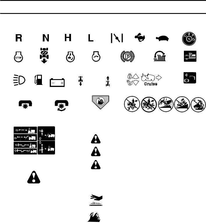
These symbols may appear on your tractor or in literature supplied with the product. Learn and understand their meaning.
REVERSE |
NEUTRAL |
HIGH |
|
LOW |
|
CHOKE |
|
|
IGNITION SWITCH |
|
|
|
|
|
|
|
|
|
|
REVERSE |
ENGINE ON |
ENGINE START |
PARKING BRAKE MOWER HEIGHT |
MOWER LIFT |
|||||
OPERATION |
|
|
|
|
|
|
|
|
|
SYSTEM (ROS) |
|
|
|
|
|
|
|
|
|
LIGHTS ON |
BATTERY |
REVERSE |
FORWARD |
CRUISE CONTROL |
|
CLUTCH/BRAKE |
|||
|
PEDAL |
||||||||
|
|
|
|
|
|
|
|
|
|
|
|
|
|
|
|
|
|
15 |
15 |
|
|
|
|
|
|
|
|
|
|
ATTACHMENT |
ATTACHMENT |
|
DANGER, KEEP HANDS |
KEEP AREA CLEAR |
SLOPE HAZARDS |
||||
CLUTCH DISENGAGED CLUTCH ENGAGED |
AND FEET AWAY |
||||||||
(SEE SAFETY RULES SECTION)
FREE WHEEL (Automatic Models only)
DANGER indicates a hazard which, if not avoided, will result in death or serious injury.
WARNING indicates a hazard which, if not avoided, could result in death or serious injury.
CAUTION indicates a hazard which, if not avoided, might result in minor or moderate injury.
CAUTION when used without the alert symbol, indicates a situation that could result in damage to the tractor and/or engine.
Failure to follow instructions could result in serious injury or death. The safety alert symbol is used to identify safety information about hazards which can result in death, serious injury and/or property damage.
HOT SURFACES indicates a hazard which,
if not avoided, could result in death, serious injury and/or property damage.
FIRE indicates a hazard which, if not avoided, could result in death, serious injury and/or property damage.
10
OPERATION
KNOW YOUR TRACTOR
READ THIS MANUAL AND SAFETY RULES BEFORE OPERATING YOUR TRACTOR
Compare the illustrations with your tractor to familiarize yourself with the locations of various controls and adjustments. Save this manual for future reference.
D P H G
E
 F
F
B
N
A
C
M K
J
L
Fig. 16
Our tractors conform to the applicable safety standards of the American National Standards Institute.
(A)ATTACHMENT LIFT LEVER - Used to raise and lower the mower or other attachments mounted to your tractor.
(B)BRAKE PEDAL - Used for braking the tractor and starting the engine.
(C)PARKING BRAKE - Locks clutch/brake pedal into the brake position.
(D)THROTTLE - Used for starting and controlling engine speed.
(E)ATTACHMENT CLUTCH SWITCH - Used to engage the mower blades or other attachments mounted to your tractor.
(F)IGNITION SWITCH - Used for starting and stopping the engine.
(G)REVERSE OPERATION SYSTEM (ROS) "ON" POSITION - Allows operation of mower or other powered attachment while in reverse.
(H) LIGHT SWITCH - Turns the headlights on and off.
(J)CRUISE CONTROL LEVER - Used to set forward movement of tractor at desired speed without holding the forward drive pedal.
(K)FORWARD DRIVE PEDAL - Used for forward movement of tractor.
(L)REVERSE DRIVE PEDAL - Used for reverse movement of tractor.
(M)FREEWHEEL CONTROL - Disengages transmission for pushing or slowly towing the tractor with the engine off.
(N)CHOKE CONTROL - Used when starting a cold engine.
(P) SERVICE REMINDER / HOUR METER - Indicates when service is required for the engine and mower.
11
 Loading...