


 Loading...
HP P63x0/P65x0 Enterprise Virtual Array
User Guide
Abstract
This document describes the hardware and general operation of the P63x0/P65x0 EVA.
HP Part Number: 5697-2486
Published: September 2013
Edition: 5

© Copyright 2011, 2013 Hewlett-Packard Development Company, L.P.
The information contained herein is subject to change without notice. The only warranties for HP products and services are set forth in the express warranty statements accompanying such products and services. Nothing herein should be construed as constituting an additional warranty. HP shall not be liable for technical or editorial errors or omissions contained herein.
Warranty
To obtain a copy of the warranty for this product, see the warranty information website:
http://www.hp.com/go/storagewarranty
Acknowledgments
Microsoft® and Windows® are U.S. registered trademarks of Microsoft Corporation.
Java® and Oracle® are registered U.S. trademark of Oracle Corporation or its affiliates.
Intel® and Itanium® are registered trademarks of Intel Corporation or its subsidiaries in the United States and other countries.

Contents |
|
1 P63x0/P65x0 EVA hardware.................................................................... |
13 |
SAS disk enclosures................................................................................................................ |
13 |
Small Form Factor disk enclosure chassis............................................................................... |
13 |
Front view.................................................................................................................... |
13 |
Rear view..................................................................................................................... |
14 |
Drive bay numbering..................................................................................................... |
14 |
Large Form Factor disk enclosure chassis............................................................................... |
14 |
Front view.................................................................................................................... |
14 |
Rear view..................................................................................................................... |
15 |
Drive bay numbering..................................................................................................... |
15 |
Disk drives........................................................................................................................ |
15 |
Disk drive LEDs............................................................................................................. |
15 |
Disk drive blanks........................................................................................................... |
16 |
Front status and UID module................................................................................................ |
16 |
Front UID module LEDs................................................................................................... |
16 |
Unit identification (UID) button........................................................................................ |
17 |
Power supply module.......................................................................................................... |
17 |
Power supply LED.......................................................................................................... |
17 |
Fan module....................................................................................................................... |
17 |
Fan module LED............................................................................................................ |
18 |
I/O module...................................................................................................................... |
18 |
I/O module LEDs.......................................................................................................... |
19 |
Rear power and UID module............................................................................................... |
19 |
Rear power and UID module LEDs................................................................................... |
20 |
Unit identification (UID) button........................................................................................ |
21 |
Power on/standby button............................................................................................... |
21 |
SAS cables....................................................................................................................... |
21 |
Controller enclosure................................................................................................................ |
21 |
Controller status indicators.................................................................................................. |
24 |
Controller status LEDs..................................................................................................... |
25 |
Power supply module.......................................................................................................... |
26 |
Battery module.................................................................................................................. |
27 |
Fan module....................................................................................................................... |
27 |
Management module......................................................................................................... |
28 |
iSCSI and iSCSI/FCoE recessed maintenance button.............................................................. |
28 |
Reset the iSCSI or iSCSI/FCoE module and boot the primary image.................................... |
29 |
Reset iSCSI or iSCSI/FCoE MGMT port IP address............................................................. |
29 |
Enable iSCSI or iSCSI/FCoE MGMT port DHCP address.................................................... |
29 |
Reset the iSCSI or iSCSI/FCoE module to factory defaults................................................... |
29 |
HSV controller cabling............................................................................................................ |
29 |
Storage system racks .............................................................................................................. |
30 |
Rack configurations............................................................................................................ |
30 |
Power distribution units............................................................................................................ |
31 |
PDU 1.............................................................................................................................. |
31 |
PDU 2.............................................................................................................................. |
31 |
PDMs............................................................................................................................... |
32 |
Rack AC power distribution................................................................................................. |
33 |
Moving and stabilizing a rack.................................................................................................. |
33 |
2 P63x0/P65x0 EVA operation.................................................................... |
36 |
Best practices......................................................................................................................... |
36 |
Operating tips and information................................................................................................ |
36 |
Contents 3
Reserving adequate free space............................................................................................ |
36 |
Using SAS-midline disk drives.............................................................................................. |
36 |
Failback preference setting for HSV controllers....................................................................... |
36 |
Changing virtual disk failover/failback setting.................................................................. |
38 |
Implicit LUN transition......................................................................................................... |
38 |
Recovery CD..................................................................................................................... |
39 |
Adding disk drives to the storage system............................................................................... |
39 |
Handling fiber optic cables................................................................................................. |
39 |
Storage system shutdown and startup........................................................................................ |
40 |
Powering on disk enclosures................................................................................................ |
40 |
Powering off disk enclosures................................................................................................ |
41 |
Shutting down the storage system from HP P6000 Command View........................................... |
41 |
Shutting down the storage system from the array controller...................................................... |
41 |
Starting the storage system.................................................................................................. |
41 |
Restarting the iSCSI or iSCSI/FCoE module .......................................................................... |
42 |
Using the management module................................................................................................ |
43 |
Connecting to the management module................................................................................ |
43 |
Connecting through a public network............................................................................... |
44 |
Connecting through a private network.............................................................................. |
45 |
Accessing HP P6000 Command View on the management module.......................................... |
45 |
Changing the host port default operating mode..................................................................... |
45 |
Saving storage system configuration data................................................................................... |
46 |
Saving or restoring the iSCSI or iSCSI/FCoE module configuration........................................... |
48 |
3 Configuring application servers.................................................................. |
50 |
Overview.............................................................................................................................. |
50 |
Clustering.............................................................................................................................. |
50 |
Multipathing.......................................................................................................................... |
50 |
Installing Fibre Channel adapters.............................................................................................. |
50 |
Testing connections to the array................................................................................................ |
51 |
Adding hosts.......................................................................................................................... |
51 |
Creating and presenting virtual disks......................................................................................... |
52 |
Verifying virtual disk access from the host................................................................................... |
52 |
Configuring virtual disks from the host....................................................................................... |
52 |
HP-UX................................................................................................................................... |
52 |
Scanning the bus............................................................................................................... |
52 |
Creating volume groups on a virtual disk using vgcreate......................................................... |
53 |
IBM AIX................................................................................................................................ |
54 |
Accessing IBM AIX utilities.................................................................................................. |
54 |
Adding hosts..................................................................................................................... |
54 |
Creating and presenting virtual disks.................................................................................... |
54 |
Verifying virtual disks from the host....................................................................................... |
54 |
Linux..................................................................................................................................... |
55 |
Driver failover mode........................................................................................................... |
55 |
Installing a QLogic driver.................................................................................................... |
55 |
Upgrading Linux components.............................................................................................. |
56 |
Upgrading qla2x00 RPMs.............................................................................................. |
56 |
Detecting third-party storage........................................................................................... |
56 |
Compiling the driver for multiple kernels........................................................................... |
57 |
Uninstalling the Linux components........................................................................................ |
57 |
Using the source RPM......................................................................................................... |
57 |
HBA drivers....................................................................................................................... |
58 |
Verifying virtual disks from the host....................................................................................... |
58 |
OpenVMS............................................................................................................................. |
58 |
4Contents
Updating the AlphaServer console code, Integrity Server console code, and Fibre Channel FCA |
|
firmware........................................................................................................................... |
58 |
Verifying the Fibre Channel adapter software installation........................................................ |
58 |
Console LUN ID and OS unit ID........................................................................................... |
59 |
Adding OpenVMS hosts..................................................................................................... |
59 |
Scanning the bus............................................................................................................... |
60 |
Configuring virtual disks from the OpenVMS host................................................................... |
61 |
Setting preferred paths....................................................................................................... |
61 |
Oracle Solaris........................................................................................................................ |
61 |
Loading the operating system and software........................................................................... |
62 |
Configuring FCAs with the Oracle SAN driver stack............................................................... |
62 |
Configuring Emulex FCAs with the lpfc driver.................................................................... |
62 |
Configuring QLogic FCAs with the qla2300 driver............................................................. |
64 |
Fabric setup and zoning..................................................................................................... |
65 |
Oracle StorEdge Traffic Manager (MPxIO)/Oracle Storage Multipathing.................................. |
65 |
Configuring with Veritas Volume Manager............................................................................ |
66 |
Configuring virtual disks from the host................................................................................... |
67 |
Verifying virtual disks from the host.................................................................................. |
68 |
Labeling and partitioning the devices............................................................................... |
69 |
VMware................................................................................................................................ |
70 |
Configuring the EVA with VMware host servers...................................................................... |
70 |
Configuring an ESX server .................................................................................................. |
70 |
Setting the multipathing policy........................................................................................ |
71 |
Verifying virtual disks from the host....................................................................................... |
73 |
HP P6000 EVA Software Plug-in for VMware VAAI................................................................. |
73 |
System prerequisites...................................................................................................... |
73 |
Enabling vSphere Storage API for Array Integration (VAAI)................................................. |
73 |
Installing the VAAI Plug-in............................................................................................... |
74 |
Installation overview................................................................................................. |
74 |
Installing the HP EVA VAAI Plug-in using ESX host console utilities................................... |
75 |
Installing the HP VAAI Plug-in using vCLI/vMA............................................................. |
76 |
Installing the VAAI Plug-in using VUM......................................................................... |
78 |
Uninstalling the VAAI Plug-in........................................................................................... |
80 |
Uninstalling VAAI Plug-in using the automated script (hpeva.pl)....................................... |
80 |
Uninstalling VAAI Plug-in using vCLI/vMA (vihostupdate)............................................... |
80 |
Uninstalling VAAI Plug-in using VMware native tools (esxupdate).................................... |
81 |
4 Replacing array components...................................................................... |
82 |
Customer self repair (CSR)....................................................................................................... |
82 |
Parts-only warranty service.................................................................................................. |
82 |
Best practices for replacing hardware components...................................................................... |
82 |
Component replacement videos........................................................................................... |
82 |
Verifying component failure................................................................................................. |
82 |
Identifying the spare part.................................................................................................... |
82 |
Replaceable parts................................................................................................................... |
83 |
Replacing the failed component................................................................................................ |
85 |
Replacement instructions.......................................................................................................... |
85 |
5 iSCSI or iSCSI/FCoE configuration rules and guidelines................................ |
87 |
iSCSI or iSCSI/FCoE module rules and supported maximums ...................................................... |
87 |
HP P6000 Command View and iSCSI or iSCSI/FCoE module management rules and guidelines...... |
87 |
HP P63x0/P65x0 EVA storage system software.......................................................................... |
87 |
Fibre Channel over Ethernet switch and fabric support................................................................. |
87 |
Operating system and multipath software support....................................................................... |
90 |
iSCSI initiator rules, guidelines, and support .............................................................................. |
91 |
General iSCSI initiator rules and guidelines .......................................................................... |
91 |
Contents 5
Apple Mac OS X iSCSI initiator rules and guidelines.............................................................. |
91 |
Microsoft Windows iSCSI Initiator rules and guidelines........................................................... |
91 |
Linux iSCSI Initiator rules and guidelines .............................................................................. |
92 |
Solaris iSCSI Initiator rules and guidelines............................................................................. |
92 |
VMware iSCSI Initiator rules and guidelines.......................................................................... |
93 |
Supported IP network adapters ................................................................................................ |
93 |
IP network requirements .......................................................................................................... |
93 |
Set up the iSCSI Initiator.......................................................................................................... |
94 |
Windows.......................................................................................................................... |
94 |
Multipathing..................................................................................................................... |
99 |
Installing the MPIO feature for Windows Server 2012........................................................... |
100 |
Installing the MPIO feature for Windows Server 2008.......................................................... |
103 |
Installing the MPIO feature for Windows Server 2003.......................................................... |
104 |
About Microsoft Windows Server 2003 scalable networking pack......................................... |
105 |
SNP setup with HP NC 3xxx GbE multifunction adapter................................................... |
105 |
iSCSI Initiator version 3.10 setup for Apple Mac OS X (single-path)........................................ |
105 |
Set up the iSCSI Initiator for Apple Mac OS X................................................................. |
106 |
Storage setup for Apple Mac OS X................................................................................ |
109 |
iSCSI Initiator setup for Linux............................................................................................. |
109 |
Installing and configuring the SUSE Linux Enterprise 10 iSCSI driver................................... |
109 |
Installing and configuring for Red Hat 5.................................................................... |
111 |
Installing and configuring for Red Hat 4 and SUSE 9.................................................. |
112 |
Installing the initiator for Red Hat 3 and SUSE 8......................................................... |
112 |
Assigning device names............................................................................................... |
112 |
Target bindings........................................................................................................... |
113 |
Mounting file systems................................................................................................... |
114 |
Unmounting file systems............................................................................................... |
114 |
Presenting EVA storage for Linux.................................................................................... |
115 |
Setting up the iSCSI Initiator for VMware............................................................................ |
115 |
Configuring multipath with the Solaris 10 iSCSI Initiator........................................................ |
117 |
MPxIO overview......................................................................................................... |
118 |
Preparing the host system........................................................................................ |
118 |
Enabling MPxIO for HP P63x0/P65x0 EVA............................................................... |
118 |
Enable iSCSI target discovery................................................................................... |
120 |
Modify target parameter MaxRecvDataSegLen........................................................... |
121 |
Monitor Multipath devices....................................................................................... |
122 |
Managing and Troubleshooting Solaris iSCSI Multipath devices................................... |
123 |
Configuring Microsoft MPIO iSCSI devices.......................................................................... |
123 |
Load balancing features of Microsoft MPIO for iSCSI............................................................ |
124 |
Microsoft MPIO with QLogic iSCSI HBA.............................................................................. |
125 |
Installing the QLogic iSCSI HBA.................................................................................... |
125 |
Installing the Microsoft iSCSI Initiator services and MPIO.................................................. |
125 |
Configuring the QLogic iSCSI HBA................................................................................ |
125 |
Adding targets to QLogic iSCSI Initiator......................................................................... |
126 |
Presenting LUNs to the QLogic iSCSI Initiator.................................................................. |
127 |
Installing the HP MPIO Full Featured DSM for EVA........................................................... |
128 |
Microsoft Windows Cluster support.................................................................................... |
129 |
Microsoft Cluster Server for Windows 2003................................................................... |
129 |
Requirements.............................................................................................................. |
129 |
Setting the Persistent Reservation registry key................................................................... |
129 |
Microsoft Cluster Server for Windows 2008................................................................... |
130 |
Requirements......................................................................................................... |
130 |
Setting up authentication .................................................................................................. |
131 |
CHAP restrictions ............................................................................................................ |
131 |
Microsoft Initiator CHAP secret restrictions .......................................................................... |
131 |
6Contents
Linux version................................................................................................................... |
132 |
ATTO Macintosh Chap restrictions ..................................................................................... |
132 |
Recommended CHAP policies ........................................................................................... |
132 |
iSCSI session types .......................................................................................................... |
132 |
The iSCSI or iSCSI/FCoE controller CHAP modes ................................................................ |
132 |
Enabling single–direction CHAP during discovery and normal session.................................... |
132 |
Enabling CHAP for the iSCSI or iSCSI/FCoE module-discovered iSCSI initiator entry ................ |
134 |
Enable CHAP for the Microsoft iSCSI Initiator....................................................................... |
135 |
Enable CHAP for the open-iscsi iSCSI Initiator ..................................................................... |
135 |
Enabling single–direction CHAP during discovery and bi-directional CHAP during normal session |
|
..................................................................................................................................... |
136 |
Enabling bi-directional CHAP during discovery and single–direction CHAP during normal |
|
session........................................................................................................................... |
138 |
Enabling bi-directional CHAP during discovery and bi-directional CHAP during normal session... |
140 |
Enable CHAP for the open-iscsi iSCSI Initiator...................................................................... |
142 |
iSCSI and FCoE thin provision handling.............................................................................. |
144 |
6 Single path implementation..................................................................... |
149 |
Installation requirements........................................................................................................ |
149 |
Recommended mitigations..................................................................................................... |
149 |
Supported configurations....................................................................................................... |
150 |
General configuration components..................................................................................... |
150 |
Connecting a single path HBA server to a switch in a fabric zone.......................................... |
150 |
HP-UX configuration.............................................................................................................. |
152 |
Requirements................................................................................................................... |
152 |
HBA configuration............................................................................................................ |
152 |
Risks.............................................................................................................................. |
152 |
Limitations....................................................................................................................... |
152 |
Windows Server 2003 (32-bit) ,Windows Server 2008 (32–bit) , and Windows Server 2012 (32–bit) |
|
configurations...................................................................................................................... |
153 |
Requirements................................................................................................................... |
153 |
HBA configuration............................................................................................................ |
153 |
Risks.............................................................................................................................. |
153 |
Limitations....................................................................................................................... |
154 |
Windows Server 2003 (64-bit) and Windows Server 2008 (64–bit) configurations....................... |
154 |
Requirements................................................................................................................... |
154 |
HBA configuration............................................................................................................ |
154 |
Risks.............................................................................................................................. |
155 |
Limitations....................................................................................................................... |
155 |
Oracle Solaris configuration................................................................................................... |
155 |
Requirements................................................................................................................... |
155 |
HBA configuration............................................................................................................ |
156 |
Risks.............................................................................................................................. |
156 |
Limitations....................................................................................................................... |
156 |
OpenVMS configuration........................................................................................................ |
157 |
Requirements................................................................................................................... |
157 |
HBA configuration............................................................................................................ |
157 |
Risks.............................................................................................................................. |
157 |
Limitations....................................................................................................................... |
158 |
Xen configuration................................................................................................................. |
158 |
Requirements................................................................................................................... |
158 |
HBA configuration............................................................................................................ |
158 |
Risks.............................................................................................................................. |
159 |
Limitations....................................................................................................................... |
159 |
Linux (32-bit) configuration..................................................................................................... |
159 |
Contents 7
Requirements................................................................................................................... |
159 |
HBA configuration............................................................................................................ |
160 |
Risks.............................................................................................................................. |
160 |
Limitations....................................................................................................................... |
160 |
Linux (Itanium) configuration................................................................................................... |
160 |
Requirements................................................................................................................... |
160 |
HBA configuration............................................................................................................ |
161 |
Risks.............................................................................................................................. |
161 |
Limitations....................................................................................................................... |
161 |
IBM AIX configuration........................................................................................................... |
162 |
Requirements................................................................................................................... |
162 |
HBA configuration............................................................................................................ |
162 |
Risks.............................................................................................................................. |
162 |
Limitations....................................................................................................................... |
162 |
VMware configuration........................................................................................................... |
163 |
Requirements................................................................................................................... |
163 |
HBA configuration............................................................................................................ |
163 |
Risks.............................................................................................................................. |
163 |
Limitations....................................................................................................................... |
164 |
Mac OS configuration........................................................................................................... |
164 |
Failure scenarios................................................................................................................... |
164 |
HP-UX............................................................................................................................. |
164 |
Windows Servers............................................................................................................. |
165 |
Oracle Solaris................................................................................................................. |
165 |
OpenVMS...................................................................................................................... |
165 |
Linux.............................................................................................................................. |
166 |
IBM AIX.......................................................................................................................... |
167 |
VMware......................................................................................................................... |
167 |
Mac OS......................................................................................................................... |
168 |
7 Troubleshooting...................................................................................... |
169 |
If the disk enclosure does not initialize..................................................................................... |
169 |
Diagnostic steps................................................................................................................... |
169 |
Is the enclosure front fault LED amber?................................................................................ |
169 |
Is the enclosure rear fault LED amber?................................................................................. |
169 |
Is the power on/standby button LED amber?....................................................................... |
170 |
Is the power supply LED amber?........................................................................................ |
170 |
Is the I/O module fault LED amber?.................................................................................... |
170 |
Is the fan LED amber?....................................................................................................... |
171 |
Effects of a disk drive failure................................................................................................... |
171 |
Compromised fault tolerance............................................................................................. |
171 |
Factors to consider before replacing disk drives........................................................................ |
171 |
Automatic data recovery (rebuild)........................................................................................... |
172 |
Time required for a rebuild................................................................................................ |
172 |
Failure of another drive during rebuild................................................................................ |
173 |
Handling disk drive failures............................................................................................... |
173 |
iSCSI module diagnostics and troubleshooting.......................................................................... |
173 |
iSCSI and iSCSI/FCoE diagnostics..................................................................................... |
173 |
Locate the iSCSI or iSCSI/FCoE module......................................................................... |
174 |
iSCSI or iSCSI/FCoE module's log data......................................................................... |
175 |
iSCSI or iSCSI/FCoE module statistics............................................................................ |
175 |
Troubleshoot using HP P6000 Command View................................................................ |
175 |
Issues and solutions.......................................................................................................... |
175 |
Issue: HP P6000 Command View does not discover the iSCSI or iSCSI/FCoE modules......... |
175 |
Issue: Initiator cannot login to iSCSI or iSCSI/FCoE module target..................................... |
176 |
8Contents
Issue: Initiator logs in to iSCSI or iSCSI/FCoE controller target but EVA assigned LUNs are not |
|
appearing on the initiator............................................................................................ |
176 |
Issue: EVA presented virtual disk is not seen by the initiator............................................... |
176 |
Issue: Windows initiators may display Reconnecting if NIC MTU changes after connection has |
|
logged in................................................................................................................... |
177 |
Issue: When communication between HP P6000 Command View and iSCSI or iSCSI/FCoE |
|
module is down, use following options:.......................................................................... |
177 |
HP P6000 Command View issues and solutions................................................................... |
178 |
8 Error messages....................................................................................... |
180 |
9 Support and other resources.................................................................... |
197 |
Contacting HP...................................................................................................................... |
197 |
HP technical support........................................................................................................ |
197 |
Subscription service.......................................................................................................... |
197 |
Documentation feedback.................................................................................................. |
197 |
Related documentation.......................................................................................................... |
197 |
Documents...................................................................................................................... |
197 |
Websites........................................................................................................................ |
197 |
Typographic conventions....................................................................................................... |
198 |
Customer self repair.............................................................................................................. |
198 |
Rack stability........................................................................................................................ |
199 |
A Regulatory compliance notices................................................................. |
200 |
Regulatory compliance identification numbers.......................................................................... |
200 |
Federal Communications Commission notice............................................................................ |
200 |
FCC rating label.............................................................................................................. |
200 |
Class A equipment...................................................................................................... |
200 |
Class B equipment...................................................................................................... |
200 |
Declaration of Conformity for products marked with the FCC logo, United States only............... |
201 |
Modification................................................................................................................... |
201 |
Cables........................................................................................................................... |
201 |
Canadian notice (Avis Canadien)........................................................................................... |
201 |
Class A equipment........................................................................................................... |
201 |
Class B equipment........................................................................................................... |
201 |
European Union notice.......................................................................................................... |
201 |
Japanese notices.................................................................................................................. |
202 |
Japanese VCCI-A notice.................................................................................................... |
202 |
Japanese VCCI-B notice.................................................................................................... |
202 |
Japanese VCCI marking................................................................................................... |
202 |
Japanese power cord statement......................................................................................... |
202 |
Korean notices..................................................................................................................... |
202 |
Class A equipment........................................................................................................... |
202 |
Class B equipment........................................................................................................... |
203 |
Taiwanese notices................................................................................................................. |
203 |
BSMI Class A notice......................................................................................................... |
203 |
Taiwan battery recycle statement........................................................................................ |
203 |
Turkish recycling notice.......................................................................................................... |
203 |
Vietnamese Information Technology and Communications compliance marking............................. |
203 |
Laser compliance notices....................................................................................................... |
204 |
English laser notice.......................................................................................................... |
204 |
Dutch laser notice............................................................................................................ |
204 |
French laser notice........................................................................................................... |
204 |
German laser notice......................................................................................................... |
205 |
Italian laser notice............................................................................................................ |
205 |
Japanese laser notice....................................................................................................... |
205 |
Contents 9
Spanish laser notice......................................................................................................... |
206 |
Recycling notices.................................................................................................................. |
206 |
English recycling notice.................................................................................................... |
206 |
Bulgarian recycling notice................................................................................................. |
206 |
Czech recycling notice...................................................................................................... |
206 |
Danish recycling notice..................................................................................................... |
206 |
Dutch recycling notice....................................................................................................... |
207 |
Estonian recycling notice................................................................................................... |
207 |
Finnish recycling notice..................................................................................................... |
207 |
French recycling notice..................................................................................................... |
207 |
German recycling notice................................................................................................... |
207 |
Greek recycling notice...................................................................................................... |
207 |
Hungarian recycling notice............................................................................................... |
208 |
Italian recycling notice...................................................................................................... |
208 |
Latvian recycling notice..................................................................................................... |
208 |
Lithuanian recycling notice................................................................................................ |
208 |
Polish recycling notice....................................................................................................... |
208 |
Portuguese recycling notice............................................................................................... |
209 |
Romanian recycling notice................................................................................................ |
209 |
Slovak recycling notice..................................................................................................... |
209 |
Spanish recycling notice................................................................................................... |
209 |
Swedish recycling notice................................................................................................... |
209 |
Battery replacement notices................................................................................................... |
210 |
Dutch battery notice......................................................................................................... |
210 |
French battery notice........................................................................................................ |
210 |
German battery notice...................................................................................................... |
211 |
Italian battery notice........................................................................................................ |
211 |
Japanese battery notice.................................................................................................... |
212 |
Spanish battery notice...................................................................................................... |
212 |
B Non-standard rack specifications.............................................................. |
213 |
Internal component envelope.................................................................................................. |
213 |
EIA310-D standards.............................................................................................................. |
213 |
EVA cabinet measures and tolerances..................................................................................... |
213 |
Weights, dimensions and component CG measurements........................................................... |
214 |
Airflow and Recirculation....................................................................................................... |
214 |
Component Airflow Requirements....................................................................................... |
214 |
Rack Airflow Requirements................................................................................................ |
214 |
Configuration Standards........................................................................................................ |
214 |
UPS Selection....................................................................................................................... |
214 |
Shock and vibration specifications.......................................................................................... |
215 |
C Command reference............................................................................... |
217 |
Command syntax.................................................................................................................. |
217 |
Command line completion................................................................................................ |
217 |
Authority requirements...................................................................................................... |
217 |
Commands.......................................................................................................................... |
217 |
Admin............................................................................................................................ |
218 |
Beacon........................................................................................................................... |
218 |
Clear............................................................................................................................. |
218 |
Date.............................................................................................................................. |
219 |
Exit................................................................................................................................ |
219 |
FRU................................................................................................................................ |
220 |
Help.............................................................................................................................. |
220 |
History........................................................................................................................... |
222 |
Image............................................................................................................................ |
222 |
10 Contents
Initiator........................................................................................................................... |
223 |
Logout............................................................................................................................ |
225 |
Lunmask......................................................................................................................... |
225 |
Passwd........................................................................................................................... |
228 |
Ping............................................................................................................................... |
229 |
Quit............................................................................................................................... |
230 |
Reboot........................................................................................................................... |
230 |
Reset.............................................................................................................................. |
230 |
Save.............................................................................................................................. |
231 |
Set................................................................................................................................. |
231 |
Set alias......................................................................................................................... |
232 |
Set CHAP....................................................................................................................... |
233 |
Set FC............................................................................................................................ |
233 |
Set features..................................................................................................................... |
234 |
Set iSCSI........................................................................................................................ |
235 |
Set iSNS......................................................................................................................... |
236 |
Set Mgmt........................................................................................................................ |
236 |
Set NTP.......................................................................................................................... |
237 |
Set properties.................................................................................................................. |
237 |
Set SNMP....................................................................................................................... |
238 |
Set system....................................................................................................................... |
239 |
Set VPGroups.................................................................................................................. |
239 |
Show............................................................................................................................. |
240 |
Show CHAP.................................................................................................................... |
242 |
Show FC........................................................................................................................ |
242 |
Show features.................................................................................................................. |
244 |
Show initiators................................................................................................................. |
244 |
Show initiators LUN mask................................................................................................. |
246 |
Show iSCSI..................................................................................................................... |
247 |
Show iSNS..................................................................................................................... |
249 |
Show logs....................................................................................................................... |
249 |
Show LUNinfo................................................................................................................. |
250 |
Show LUNs..................................................................................................................... |
251 |
Show lunmask................................................................................................................. |
252 |
Show memory................................................................................................................. |
252 |
Show mgmt..................................................................................................................... |
253 |
Show NTP...................................................................................................................... |
253 |
Show perf....................................................................................................................... |
254 |
Show presented targets..................................................................................................... |
255 |
Show properties.............................................................................................................. |
258 |
Show SNMP................................................................................................................... |
259 |
Show stats...................................................................................................................... |
259 |
Show system................................................................................................................... |
261 |
Show targets................................................................................................................... |
262 |
Show VPGroups............................................................................................................... |
262 |
Shutdown....................................................................................................................... |
263 |
Target............................................................................................................................ |
263 |
Traceroute....................................................................................................................... |
264 |
D Using the iSCSI CLI................................................................................. |
265 |
Logging on to an iSCSI or iSCSI/FCoE module......................................................................... |
265 |
Understanding the guest account............................................................................................ |
265 |
Working with iSCSI or iSCSI/FCoE module configurations......................................................... |
266 |
Modifying a configuration................................................................................................. |
267 |
Saving and restoring iSCSI or iSCSI/FCoE controller configurations........................................ |
267 |
Contents 11
Restoring iSCSI or iSCSI/FCoE module configuration and persistent data |
................................267 |
E Simple Network Management Protocol...................................................... |
269 |
SNMP parameters................................................................................................................ |
269 |
SNMP trap configuration parameters....................................................................................... |
269 |
Management Information Base .............................................................................................. |
270 |
Network port table........................................................................................................... |
270 |
FC port table................................................................................................................... |
272 |
Initiator object table......................................................................................................... |
273 |
LUN table....................................................................................................................... |
275 |
VP group table................................................................................................................ |
277 |
Sensor table.................................................................................................................... |
278 |
Notifications........................................................................................................................ |
279 |
System information objects................................................................................................ |
280 |
Notification objects.......................................................................................................... |
280 |
Agent startup notification.................................................................................................. |
281 |
Agent shutdown notification.............................................................................................. |
281 |
Network port down notification.......................................................................................... |
281 |
FC port down notification.................................................................................................. |
281 |
Target device discovery.................................................................................................... |
282 |
Target presentation (mapping)........................................................................................... |
282 |
VP group notification........................................................................................................ |
282 |
Sensor notification........................................................................................................... |
283 |
Generic notification.......................................................................................................... |
283 |
F iSCSI and iSCSI/FCoE module log messages............................................. |
284 |
Glossary.................................................................................................. |
298 |
Index....................................................................................................... |
311 |
12 Contents
1 P63x0/P65x0 EVA hardware
The P63x0/P65x0 EVA contains the following components:
•EVA controller enclosure — Contains HSV controllers, power supplies, cache batteries, and fans. Available in FC and iSCSI options
NOTE: Compared to older models, the HP P6350 and P6550 employ newer batteries and a performance enhanced management module. They require XCS Version 11000000 or later on the P6350 and P6550 and HP P6000 Command View Version 10.1 or later on the management module. The P6300 and P6350 use the HSV340 controller while the P6500 and P6550 use the HSV360 controller.
•SAS disk enclosure — Contains disk drives, power supplies, fans, midplane, and I/O modules.
•Y-cables — Provides dual-port connectivity to the EVA controller.
•Rack — Several free standing racks are available.
SAS disk enclosures
6 Gb SAS disk enclosures are available in two models:
•Small Form Factor (SFF): Supports 25 SFF (2.5 inch) disk drives
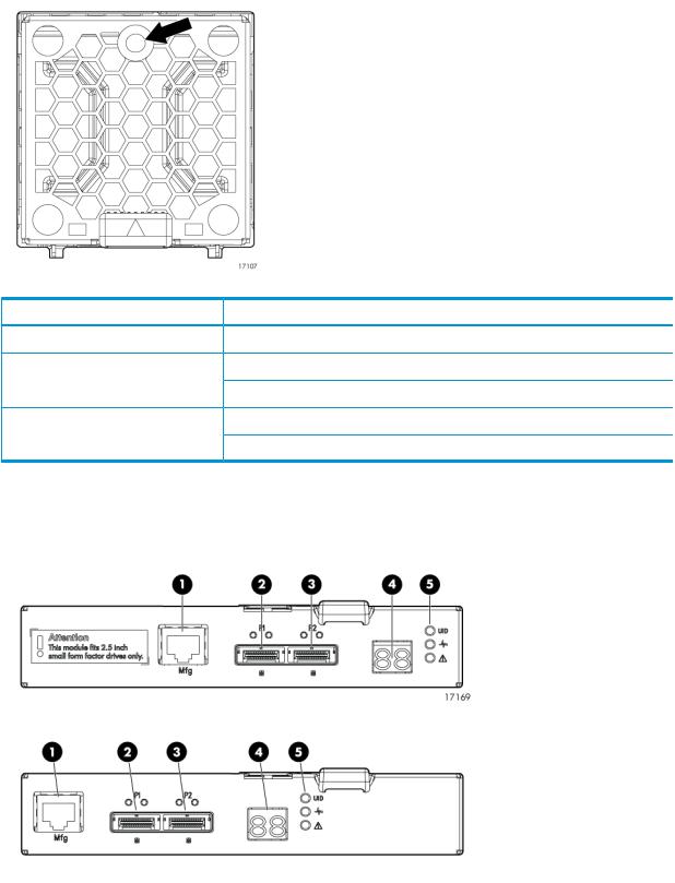
•Large Form Factor (LFF): Supports 12 LFF (3.5 inch) disk drives
•The SFF model is M6625; the LFF model is M6612.
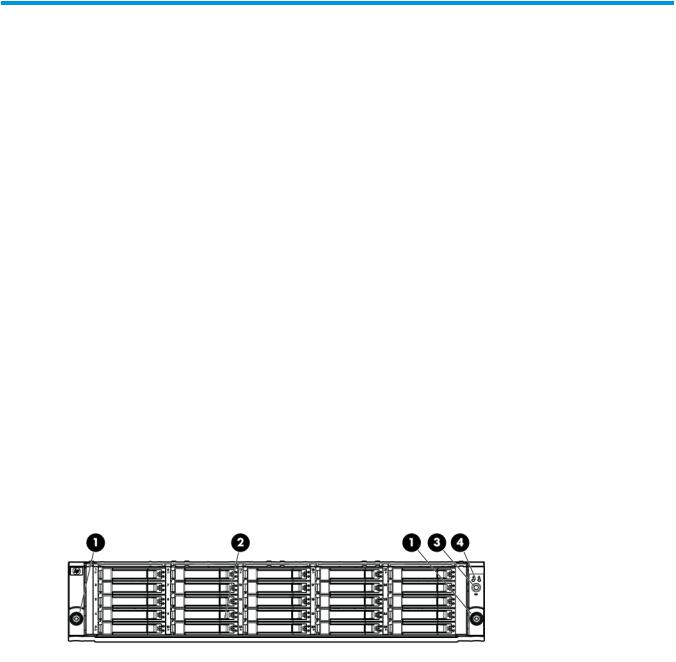
Small Form Factor disk enclosure chassis
Front view
1. Rack-mounting thumbscrew |
3. UID push button and LED |
2. Disk drive in bay 9 |
4. Enclosure status LEDs |
SAS disk enclosures 13
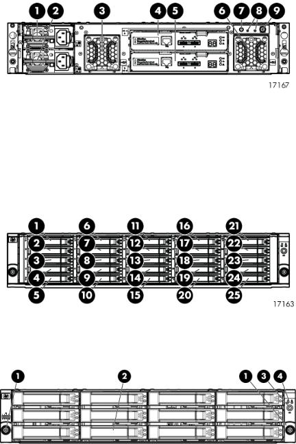
Rear view
1. Power supply 1 |
4. I/O module A |
7. UID push button and LED |
2. Power supply 2 |
5. I/O module B |
8. Enclosure status LEDs |
3. Fan 1 |
6. Fan 2 |
9. Power push button and LED |
Drive bay numbering
Disk drives mount in bays on the front of the enclosure. Bays are numbered sequentially from top to bottom and left to right. Bay numbers are indicated on the left side of each drive bay.
Large Form Factor disk enclosure chassis
Front view
1. Rack-mounting thumbscrew |
3. UID push button and LED |
2. Disk drive in bay 6 |
4. Enclosure status LEDs |
14 P63x0/P65x0 EVA hardware
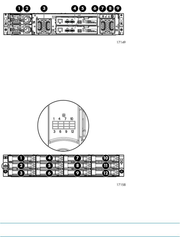
Rear view
1. Power supply 1 |
4. I/O module A |
7. UID push button and LED |
2. Power supply 2 |
5. I/O module B |
8. Enclosure status LEDs |
3. Fan 1 |
6. Fan 2 |
9. Power push button and LED |
Drive bay numbering
Disk drives mount in bays on the front of the enclosure. Bays are numbered sequentially from top to bottom and left to right. A drive-bay legend is included on the left bezel.
Disk drives
Disk drives are hot-pluggable. A variety of disk drive models are supported for use.
Disk drive LEDs
Two LEDs indicate drive status.
NOTE: The following image shows a Small Form Factor (SFF) disk drive. LED patterns are the same for SFF and LFF disk drives.
SAS disk enclosures 15

LED |
LED color |
LED status |
Description |
1. Locate/Fault |
Blue |
Slow blinking (0.5 Hz) |
Locate drive |
|
Amber |
Solid |
Drive fault |
2. Status |
Green |
Blinking (1 Hz) |
Drive is spinning up or down |
|
|
|
and is not ready |
|
|
Fast blinking (4 Hz) |
Drive activity |
|
|
Solid |
Ready for activity |
Disk drive blanks
To maintain the proper enclosure air flow, a disk drive or a disk drive blank must be installed in each drive bay. The disk drive blank maintains proper airflow within the disk enclosure.
Front status and UID module
The front status and UID module includes status LEDs and a unit identification (UID) button.
Front UID module LEDs
LED |
LED icon |
LED color |
LED status |
Description |
1. Health |
|
Green |
Off |
No power |
|
|
|
Blinking |
Enclosure is starting up and not ready, |
|
|
|
|
performing POST |
|
|
|
Solid |
Normal, power is on |
2. Fault |
|
Amber |
Off |
Normal, no fault conditions |
|
|
|
Blinking |
A fault of lesser importance was detected in the |
|
|
|
|
enclosure chassis or modules |
|
|
|
Solid |
A fault of greater importance was detected in |
|
|
|
|
the enclosure chassis or modules |
3. UID |
|
Blue |
Off |
Not being identified or power is off |
|
|
|
Blinking |
Unit is being identified from the management |
|
|
|
|
utility |
|
|
|
Solid |
Unit is being identified from the UID button |
|
|
|
|
being pushed |
16 P63x0/P65x0 EVA hardware
Unit identification (UID) button
The unit identification (UID) button helps locate an enclosure and its components. When the UID button is activated, the UID on the front and rear of the enclosure are illuminated.
NOTE: A remote session from the management utility can also illuminate the UID.
•To turn on the UID light, press the UID button. The UID light on the front and the rear of the enclosure will illuminate solid blue. (The UID on cascaded storage enclosures are not illuminated.)
•To turn off an illuminated UID light, press the UID button. The UID light on the front and the rear of the enclosure will turn off.
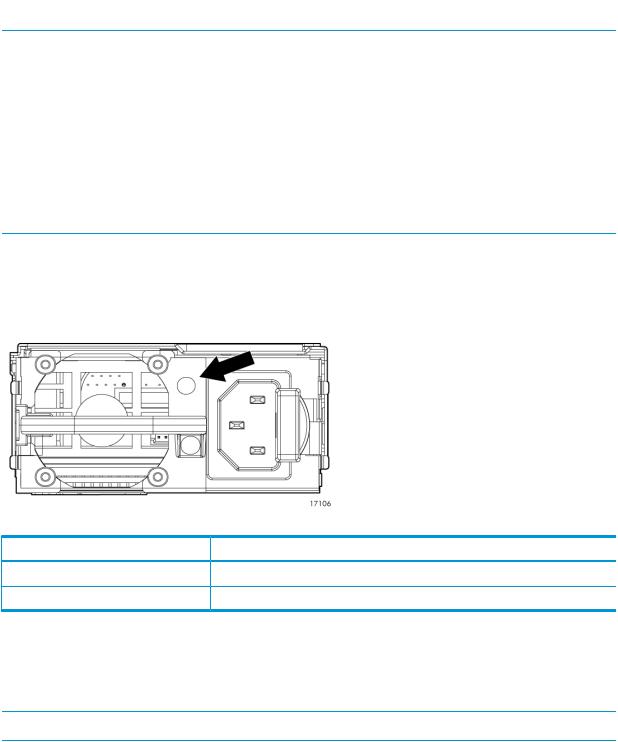
Power supply module
Two power supplies provide the necessary operating voltages to all controller enclosure components. If one power supply fails, the remaining power supply is capable of operating the enclosure. (Replace any failed component as soon as possible.)
NOTE: If one of the two power supply modules fails, it can be hot-replaced.
Power supply LED
One LED provides module status information.
LED status |
Description |
Off |
No power |
On |
Normal, no fault conditions |
Fan module
Fan modules provide cooling necessary to maintain proper operating temperature within the disk enclosure. If one fan fails, the remaining fan is capable of cooling the enclosure. (Replace any failed component as soon as possible.)
NOTE: If one of the two fan modules fail, it can be hot-replaced.
SAS disk enclosures 17
Fan module LED
One bi-color LED provides module status information.
LED color |
LED status |
Description |
Off |
Off |
No power |
Green |
Blinking |
The module is being identified |
|
Solid |
Normal, no fault conditions |
Amber |
Blinking |
Fault conditions detected |
|
Solid |
Problems detecting the module |
I/O module
The I/O module provides the interface between the disk enclosure and the host.
Each I/O module has two ports that can transmit and receive data for bidirectional operation.
1. Manufacturing diagnostic port |
4. Double 7–segment display |
2. SAS Port 1 |
5. I/O module LEDs |
3. SAS Port 2 |
|
18 P63x0/P65x0 EVA hardware

I/O module LEDs
LEDs on the I/O module provide status information about each I/O port and the entire module.
NOTE: The following image illustrates LEDs on the Small Form Factor I/O module.
LED |
LED icon |
LED color |
LED status |
Description |
1. SAS Port Link |
n/a |
Green |
Off |
No cable, no power, or port not |
|
|
|
|
connected |
|
|
|
Blinking |
The port is being identified by an |
|
|
|
|
application client |
|
|
|
Solid |
Healthy, active link |
2. SAS Port Error |
n/a |
Amber |
Off |
Normal, no errors detected |
|
|
|
Blinking |
Error detected by application client |
|
|
|
Solid |
Error, fault conditions detected on |
|
|
|
|
the port by the I/O module |
3. 7–segment |
n/a |
n/a |
Off |
No cable, no power, enclosure not |
display |
|
|
|
detected |
|
|
|
Number |
The enclosure box number |
4. UID |
|
Blue |
Off |
Not being identified or no power |
|
|
|
Solid |
Module is being identified, from |
|
|
|
|
the management utility |
5. Health |
|
Green |
Off |
No power or firmware malfunction |
|
|
|
Blinking |
Enclosure is starting up and not |
|
|
|
|
ready, performing POST |
|
|
|
Solid |
Normal, power is on |
6. Fault |
|
Amber |
Off |
Normal, no fault conditions |
|
|
|
Blinking |
A fault of lesser importance |
|
|
|
Solid |
A fault of greater importance, I/O |
|
|
|
|
failed to start |
Rear power and UID module
The rear power and UID module includes status LEDs, a unit identification (UID) button, and the power on/standby button.
SAS disk enclosures 19

Rear power and UID module LEDs
LED |
LED icon |
LED color |
Status |
Description |
1. UID |
|
Blue |
Off |
Not being identified or no |
|
|
|
|
power |
|
|
|
On |
Unit is being identified, either |
|
|
|
|
from the UID button being |
|
|
|
|
pushed or from the |
|
|
|
|
management utility |
2. Health |
|
Green |
Off |
No power |
|
|
|
Blinking |
Enclosure is starting up and |
|
|
|
|
not ready, performing POST |
|
|
|
Solid |
Normal, power is on |
3. Fault |
|
Amber |
Off |
Normal, no fault conditions |
|
|
|
Blinking |
A fault of lesser importance |
|
|
|
Solid |
A fault of greater importance |
4. On/Standby |
|
Green |
Solid |
Power is on |
|
|
Amber |
Solid |
Standby power |
20 P63x0/P65x0 EVA hardware
Unit identification (UID) button
The unit identification (UID) button helps locate an enclosure and its components. When the UID button is activated, the UID on the front and rear of the enclosure are illuminated.
NOTE: A remote session from the management utility can also illuminate the UID.
•To turn on the UID light, press the UID button. The UID light on the front and the rear of the enclosure will illuminate solid blue. (The UID on cascaded storage enclosures are not illuminated.)
•To turn off an illuminated UID light, press the UID button. The UID light on the front and the rear of the enclosure will turn off.
Power on/standby button
The power on/standby button applies either full or partial power to the enclosure chassis.
•To initially power on the enclosure, press and hold the on/standby button for a few seconds, until the LEDs begin to illuminate.
•To place an enclosure in standby, press and hold the on standby button for a few seconds, until the on/standby LED changes to amber.
NOTE: System power to the disk enclosure does not completely shut off with the power on/standby button. The standby position removes power from most of the electronics and components, but portions of the power supply and some internal circuitry remain active. To completely remove power from the system, disconnect all power cords from the device.
SAS cables
These disk enclosures use cables with mini-SAS connectors for connections to the controller and cascaded disk enclosures.
Controller enclosure
For both the P63x0 EVA and P65x0 EVA, a single enclosure contains a management module and two controllers. Two interconnected controllers ensure that the failure of a controller component does not disable the system. One controller can fully support an entire system until the defective controller, or controller component, is repaired. The controllers have an 8 Gb host port capability. The P63x0 and P65x0 EVA controllers are available in FC, FC-iSCSI, and iSCSI/FCoE versions. The controller models are HSV340 (for the P63x0) and HSV360 (for the P65x0).
Figure 1 (page 22) shows the bezel of the controller enclosure. Figure 2 (page 22) shows the front of the controller enclosure with the bezel removed.
Controller enclosure |
21 |

Figure 1 Controller enclosure (front bezel)
1. Enclosure status LEDs |
2. Front UID push button |
Figure 2 Controller enclosure (front view with bezel removed)
1. Rack-mounting thumbscrew |
8. Fan 1 normal operation LED |
2. Enclosure product number (PN) and serial number |
9. Fan 1 fault LED |
3. World Wide Number (WWN) |
10. Fan 2 |
4. Battery 1 |
11. Battery 2 |
5. Battery normal operation LED |
12. Enclosure status LEDs |
6. Battery fault LED |
13. Front UID push button |
7. Fan 1 |
|
Each P63x0 controller contains two SAS data ports. Each P65x0 controller contains four SAS data ports (made possible using Y-cables—one cable with two outputs). For both the P63x0 and P65x0 EVA, the FC controller adds four 8 Gb FC ports (Figure 3 (page 23)); the FC-iSCSI controller adds two 8 Gb FC ports and four 1 GbE iSCSI ports (Figure 4 (page 23)); and the iSCSI/FCoE controller adds two 8 Gb FC ports and two10 GbE iSCSI/FCoE ports (Figure 5 (page 24)).
22 P63x0/P65x0 EVA hardware

Figure 3 P6000 EVA FC controller enclosure (rear view)
1. Power supply 1 |
9. Enclosure power push button |
2. Controller 1 |
10. Power supply 2 |
3. Management module status LEDs |
11. DP-A and DP-B, connection to back end (storage) |
4. Ethernet port |
12. FP1 and FP2, connection to front end (host or SAN) |
5. Management module |
13. FP3 and FP4, connection to front end (host or SAN) |
6. Controller 2 |
14. Manufacturing diagnostic port |
7. Rear UID push button |
15. Controller status and fault LEDs |
8. Enclosure status LEDs |
|
Figure 4 P6000 EVA FC-iSCSI controller enclosure (rear view)
1. Power supply 1 |
10. Power supply 2 |
2. Controller 1 |
11. Serial port |
3. Management module status LEDs |
12. SW Management port |
4. Ethernet port |
13. DP-A and DP-B, connection to back-end (storage) |
5. Management module |
14. 1GbE ports 1–4 |
6. Controller 2 |
15. FP3 and FP4, connection to front end (host or SAN) |
7. Rear UID push button |
16. Manufacturing diagnostic port |
8. Enclosure status LEDs |
17. Controller status and fault LEDs |
9. Enclosure power push button |
18. iSCSI module recessed maintenance button |
Controller enclosure |
23 |

Figure 5 P6000 EVA iSCSI/FCoE controller enclosure (rear view)
1. Power supply 1 |
10. Power supply 2 |
2. Controller 1 |
11. 10GbE ports 1–2 |
3. Management module status LEDs |
12. DP-A and DP-B, connection to back-end (storage) |
4. Ethernet port |
13. Serial port |
5. Management module |
14. FP3 and FP4, connection to front end (host or SAN) |
6. Controller 2 |
15. SW Management port |
7. Rear UID push button |
16. Manufacturing diagnostic port |
8. Enclosure status LEDs |
17. Controller status and fault LEDs |
9. Enclosure power push button |
18. iSCSI/FCoE recessed maintenance button |
NOTE: The only difference between the P63x0 and P65x0 controllers is the number indicated below the SAS data ports (DP-A and DP-B). On the P63x0, 1 is displayed (Figure 6 (page 24)). On the P65x0, 1 | 2is displayed (Figure 7 (page 24)).
Figure 6 P63x0 data port numbering
Figure 7 P65x0 data port numbering
Controller status indicators
The status indicators display the operational status of the controller. The function of each indicator is described in Table 3 (page 25). During initial setup, the status indicators might not be fully operational.
Each port on the rear of the controller has an associated status indicator located directly above it. Table 1 (page 25) lists the port and its status description for the HSV340. Table 2 (page 25) lists the port and its status descriptions for the HSV340 FC-iSCSI.
24 P63x0/P65x0 EVA hardware
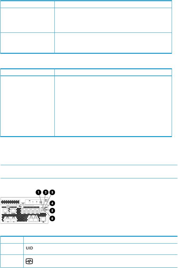
Table 1 HSV340/360 controller port status indicators
Port |
Description |
Fibre Channel host ports |
• Green — Normal operation |
•Amber — No signal detected
•Off — No SFP1 detected or the Direct Connect HP P6000 Control Panel setting is incorrect
Fibre Channel device ports |
• |
Green — Normal operation |
|
• Amber — No signal detected or the controller has failed the port |
|
|
• |
Off — No SFP1 detected |
1 On copper Fibre Channel cables, the SFP is integrated into the cable connector.
Table 2 HSV340/360 FC-iSCSI controller port status indicators
Port |
Description |
Fibre Channel switch ports |
• Green on — Normal operation or loopback port |
•Green flashing — Normal online I/O activity
•Amber on — Faulted port, disabled due to diagnostics or Portdisable command
•Amber flashing — Port with no synchronization, receiving light but not yet online or segmented port
•Off — No SFP1, no cable, no license detected.
Fibre Channel device ports |
• |
Green — Normal operation |
|
• Amber — No signal detected or the controller has failed the port |
|
|
• |
Off — No SFP1 detected |
1 On copper Fibre Channel cables, the SFP is integrated into the cable connector.
Controller status LEDs
Figure 8 (page 25) shows the location of the controller status LEDs; Table 3 (page 25) describes them.
NOTE: Figure 8 (page 25) shows an FC-iSCSI controller, however the LEDs for the FC, FC-iSCSI, and iSCSI/FCoE controllers are identical, unless specifically noted.
Figure 8 Controller status LEDs
Table 3 Controller status LEDs
Item |
LED |
Indication |
1 |
|
Blue LED identifies a specific controller within the enclosure or |
|
|
identifies the FC-iSCSI or iSCSI/FCoE module within the controller. |
2 |
|
Green LED indicates controller health. LED flashes green during |
|
|
boot and becomes solid green after boot. |
Controller enclosure |
25 |

 Table 3 Controller status LEDs (continued)
Item |
LED |
3 |
|
 Indication
Flashing amber indicates a controller termination, or the system is inoperative and attention is required. Solid amber indicates that the controller cannot reboot, and that the controller should be replaced. If both the solid amber and solid blue LEDs are lit, the controller has completed a warm removal procedure, and can be safely swapped.
4 |
MEZZ |
Only used on the FC-iSCSI and iSCSI/FCoE controllers (not on |
|
|
the FC controller). |
|
|
Amber LED indicates the FC-iSCSI or iSCSI/FCoE module status |
|
|
that is communicated to the array controller. |
|
|
Slow flashing amber LED indicates an IP address conflict on the |
|
|
management port. |
|
|
Solid amber indicates an FC-iSCSI or iSCSI/FCoE module critical |
|
|
error, or shutdown. |
5 |
|
Green LED indicates write-back cache status. Slow flashing green |
|
|
LED indicates standby power. Solid green LED indicates cache is |
|
|
good with normal AC power applied. |
6 |
|
Amber LED indicates DIMM status. The LED is off when DIMM |
|
|
status is good. Slow flashing amber indicates DIMMs are being |
|
|
powered by battery (during AC power loss). Flashing amber with |
|
|
the chassis powered up indicates a degraded battery. Solid amber |
|
|
with the chassis powered up indicates a failed battery. |
Power supply module
Two power supplies provide the necessary operating voltages to all controller enclosure components. If one power supply fails, the remaining power supply is capable of operating the enclosure. (Replace any failed component as soon as possible.)
NOTE: If one of the two power supply modules fails, it can be hot-replaced.
Figure 9 Power supply
1. Power supply |
4. Status indicator (dual-color: amber and green) |
2. AC input connector |
5. Handle |
3. Latch |
|
26 P63x0/P65x0 EVA hardware
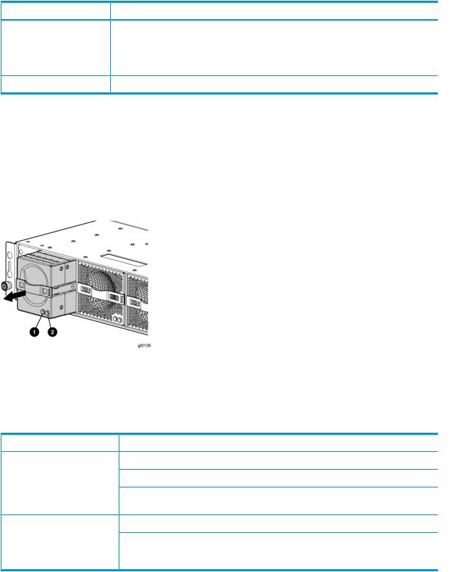
Table 4 Power supply LED status
LED color |
Description |
Amber |
• The power supply is powered up but not providing output power. |
|
• The power supply is plugged into a running chassis, but is not receiving AC input |
|
power (the fan and LED on the supply receive power from the other power supply in |
|
this situation). |
Green |
Normal, no fault conditions |
Battery module
Battery modules provide power to the controllers in the enclosure.
Figure 10 Battery module pulled out
1. Green—Normal operation LED |
2. Amber—Fault LED |
Each battery module provides power to the controller directly across from it in the enclosure.
Table 5 Battery status indicators
Status indicator |
Fault indicator |
Description |
On left—Green |
Solid green |
Normal operation. |
|
Blinking |
Maintenance in progress. |
|
Off |
Amber is on or blinking, or the enclosure is powered |
|
|
down. |
On right—Amber |
Solid amber |
Battery failure; no cache hold-up. Green will be off. |
|
Blinking amber |
Battery degraded; replace soon. Green will be off. |
|
|
(Green and amber are not on simultaneously except for |
|
|
a few seconds after power-up.) |
Fan module
Fan modules provide the cooling necessary to maintain the proper operating temperature within the controller enclosure. If one fan fails, the remaining fan is capable of cooling the enclosure.
Controller enclosure |
27 |

Figure 11 Fan module pulled out
1. Green—Fan normal operation LED 2. Amber—Fan fault LED
Table 6 Fan status indicators
Status indicator |
Fault indicator |
Description |
On left—Green |
Solid green |
Normal operation. |
|
Blinking |
Maintenance in progress. |
|
Off |
Amber is on or blinking, or the enclosure is powered |
|
|
down. |
On right—Amber |
On |
Fan failure. Green will be off. (Green and amber are |
|
|
not on simultaneously except for a few seconds after |
|
|
power-up.) |
Management module
The HP P6000 Control Panel provides a direct interface to the management module within each controller. From the HP P6000 Control Panel you can display storage system status and configuration information, shut down the storage system, and manage the password. For tasks to perform with the HP P6000 Control Panel, see the HP P6000 Control Panel online help.
The HP P6000 Control Panel provides two levels of administrator access and an interface for software updates to the management module. For additional details about the HP P6000 Control Panel, see the HP P6000 Control Panel online help.
NOTE: The HP P6350 and P6550 employ a performance-enhanced management module as well as new batteries. This requires HP P6000 Command View 10.1 or later on the management module and XCS 11000000 or later on the P6350 and P6550.
iSCSI and iSCSI/FCoE recessed maintenance button
The iSCSI and iSCSI/FCoE recessed maintenance button is the only manual user-accessible control for the module. It is used to reset or to recover a module. This maintenance button is a multifunction momentary switch and provides the following functions, each of which causes a reboot that completes in less than one minute:
•Reset the iSCSI or iSCSI/FCoE module and boot the primary image
•Reset the iSCSI or iSCSI/FCoE MGMT port IP address
•Enable iSCSI or iSCSI/FCoE MGMT port DHCP address
•Reset the iSCSI or iSCSI/FCoE module to factory defaults
28 P63x0/P65x0 EVA hardware

Reset the iSCSI or iSCSI/FCoE module and boot the primary image
Use a pointed nonmetallic tool to briefly press the maintenance button for a duration of two seconds and release it. The iSCSI or iSCSI/FCoE module responds as follows:
1.The amber MEZZ status LED illuminates once.
NOTE: Holding the maintenance button for more than two seconds but less than six seconds or until the MEZZ status LED illuminates twice, boots a secondary image, and is not recommended for field use.
2.After approximately two seconds, the power-on self-test begins, and the MEZZ status LED is turned off.
3.When the power-on self test is complete, the MEZZ status LED illuminates and flashes once per second.
Reset iSCSI or iSCSI/FCoE MGMT port IP address
Reset and restore the MGMT port IP address to the default of 192.168.0.76 or 192.168.0.82 depending on the controller 1 or 2 position.
NOTE: Setting the IP address by this method is not persistent. To make the change persistent, use the command line interface (CLI).
1.Use a pointed nonmetallic tool to briefly press the maintenance button. Release the button after six seconds and observe six extended flashes of the MEZZ status LED.
2.The iSCSI or iSCSI/FCoE module boots and sets the MGMT port to IP address 192.168.0.76 or 192.168.0.82 depending on the controller 1 or 2 position.
Enable iSCSI or iSCSI/FCoE MGMT port DHCP address
Resets the iSCSI or iSCSI/FCoE module and configure the MGMT port to use DHCP to access its IP address. Enabling DHCP by this method is not persistent. To make the change persistent, use the CLI .
1.Use a pointed nonmetallic tool to briefly press the maintenance button. Release the button after seven seconds and observe seven extended flashes of the MEZZ status LED.
2.The iSCSI or iSCSI/FCoE module boots and configures the MGMT port for DHCP.
Reset the iSCSI or iSCSI/FCoE module to factory defaults
This resets the iSCSI or iSCSI/FCoE module and restores it to the factory default configuration, with reset passwords, MGMT port IP address set to either 192.168.0.76 or 192.168.0.82 depending on the controller 1 or 2 position, Disables iSCSI ports with no IP address, erases presentations, and erases discovered initiators and targets).
1.Use a pointed nonmetallic tool to press the maintenance button. Release the button after twenty seconds and observe twenty extended flashes of the MEZZ status LED.
2.The iSCSI or iSCSI/FCoE module boots and is restored to factory defaults.
HSV controller cabling
All data cables and power cables attach to the rear of the controller. Adjacent to each data connector is a two-colored link status indicator. Table 1 (page 25) identifies the status conditions presented by these indicators.
NOTE: These indicators do not indicate whether there is communication on the link, only whether the link can transmit and receive data.
The data connections are the interfaces to the disk drive enclosures, the other controller, and the fabric. Fiber optic cables link the controllers to the fabric, and, if an expansion cabinet is part of the configuration, link the expansion cabinet drive enclosures to the loops in the main cabinet.
HSV controller cabling 29
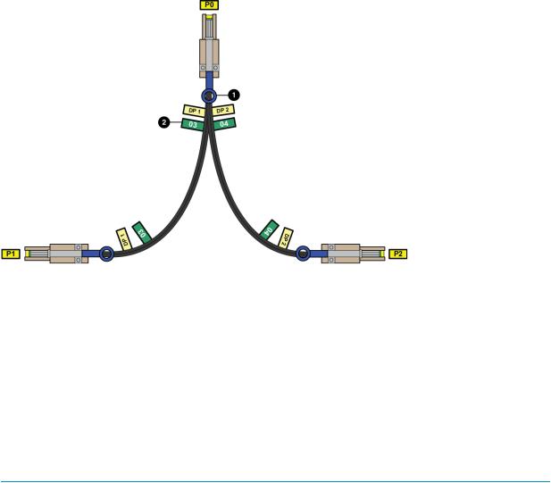
Y-cables (Figure 12 (page 30)) are used to connect the P6500 EVA and enable each controller data port to act as two ports.
Figure 12 P6500 Y-cable
1. Pull tab (may also be a release bar) |
2. Port number label |
Storage system racks
All storage system components are mounted in a rack. Each configuration includes one controller enclosure holding both controllers (the controller pair) and the disk enclosures. Each controller pair and all associated disk enclosures form a single storage system.
The rack provides the capability for mounting standard 483 mm (19 in) wide controller and disk enclosures.
NOTE: Racks and rack-mountable components are typically described using “U” measurements. “U” measurements are used to designate panel or enclosure heights. The “U” measurement is a standard of 41mm (1.6 in).
The racks provide the following:
•Unique frame and rail design—Allows fast assembly, easy mounting, and outstanding structural integrity.
•Thermal integrity—Front-to-back natural convection cooling is greatly enhanced by the innovative multi-angled design of the front door.
•Security provisions—The front and rear door are lockable, which prevents unauthorized entry.
•Flexibility—Provides easy access to hardware components for operation monitoring.
•Custom expandability—Several options allow for quick and easy expansion of the racks to create a custom solution.
Rack configurations
The standard rack for the P63x0/P65x0 EVA is the 42U HP 10000 Intelligent Series rack. The P63x0/P65x0 EVA is also supported with 22U, 36U, 42U 5642, and 47U racks. The 42U 5642 is a field-installed option. The 47U rack must be assembled on site because the cabinet height creates shipping difficulties.
For more information on HP rack offerings for the P63x0/P65x0 EVA see:
30 P63x0/P65x0 EVA hardware
Loading...