


SM0101
AXF300E
AXF300EBS
AXF300UC
AXF300W
AXF300WUN
HMDR50
CD MECHANISM CDV300DW
MD MECHANISM MDM-99X
CAUTION
DANGER
Invisible laser radiation when open and interlocks failed or defeated. AVOID DIRECT EXPOSURE TO BEAM.
GEFAHR
Unsichtbare Laser-Strahlung wenn Interlock (Blockierung) funktionsuntüchtig oder abgeschaltet. UNMITTELBAREN KONTAKT MIT DEM STRAHL UNBEDIGT VERMEIDEN.
DANGER
Faire très attention aux radiations émises par le faisceau laser invisible au défaillance du verrouillage. NENEJAMAISS'EXPOSERDIRECTEMENTAUFAISCEAU. .
VARNING
När apparaten öppnats och skyddsanordningen felar eller satts ur funktion förekommer osynlig laserstrålning. UNDVIKDIREKTBESTRÅLNING..
ADVARSEL
Ñår apparatet åbnes og beskyttelsesanordningen ikke virker eller sættes un af funktion, forekommer der usynlig laserstråling. UNDGÅDIREKTEBESTRÅLING. .
ADVARSEL
Når denne delen er apen som følge av at låsen er utkoplet eller ikke fungerer, eksisterer det usynlig laserstråling.
UNUNNGÅÅ BLIÅ BLIUTSATTFORFORDIREKTEBESTRÅLING!
VARIOITS
Laite lähettää näkymätöntä lasersäteilyä, kun se avataan ja kun sisäiset turvalukot eivät toimi.
VAROJOUTUMASTAALTTIIKSIKSI SÄTEILYLLE..
|
CONTENTS |
SPECIFICATIONS ..................................................................................................................................................... |
3 |
SERVICE POINTS ..................................................................................................................................................... |
4 |
ADJUSTMENTS ......................................................................................................................................................... |
10 |
WIRING DIAGRAMS .................................................................................................................................................. |
11 |
PRINTED WIRING BOARDS .................................................................................................................................... |
14 |
BLOCK DIAGRAM ..................................................................................................................................................... |
25 |
CIRCUIT DIAGRAM ................................................................................................................................................... |
29 |
EXPLODED VIEW ...................................................................................................................................................... |
53 |
REPLACEMENT PARTS LIST .................................................................................................................................. |
56 |
SPECIFICATIONS AND PARTS ARE SUBJECT TO CHANGE FOR IMPROVEMENT
MINI COMPONENT HI-FI SYSTEM
September 2000 HITACHI CONSUMER PRODUCTS (S)
AX-F300
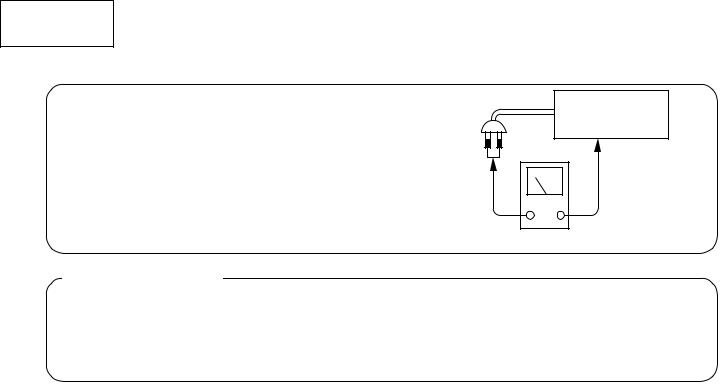
Check that exposed parts are acceptably insulated from the supply circuit before returning the repaired instrument to the customer.
•Checking method
Measure the resistance value between the both poles of attachment cup (Power supply plug) and the exposed parts (Parts such as Knob, Cover, etc. where the customer is easy to touch.) and check that the resistance value is 500 kohms or more.
SAFETY PRECAUTIONS
The following precautions should be observed when servicing.
INSTRUMENT
(Exposed part)
Insulation tester (DC 500V)
1.Since many parts in the unit have special safety-related characteristics, always use genuine Hitachi’s replacement
parts. Especially critical parts in the power circuit block should not be replaced with other makers. Critical parts are marked with  in the circuit diagram and printed wiring board.
2.Before returning a repaired unit to the customer, the service technician must thoroughly test the unit to ascertain that it is completely safe to operate without danger of electrical shock.
– 2 –

AX-F300
SPECIFICATIONS
• AM-FM TUNER AMPLIFIER (HTA-R100)
Reception frequency band: |
UC (FM:87.5~108.0MHz(100kHz step) AM:520~1710kHz(10kHz step)) |
|
|
E,EBS (FM:87.50~108.00MHz(50kHz step) MW:522~1611kHz(9kHz step) LW:153~281kHz(1kHz step)) |
|
|
W (FM:87.50~108.00MHz(50kHz step) AM:522~1611kHz(9kHz step) 520~1710kHz(10kHz step)) |
|
|
WUN (FM:76.00~108.00MHz(50kHz step) AM:522~1629kHz(9kHz step) 520~1710kHz(10kHz step)) |
|
Rated output power: |
40 W + 40 W (6W/ohms, 1kHz, T.H.D. 10%) |
|
Audio input / output jacks: |
CD input jacks, TAPE input/output jacks, AUX input jacks, MD input/output jacks, |
|
|
PRE OUT (MONO) jack, headphones jack |
|
Power supply: |
E,EBS |
: AC 230 V, 50 Hz |
|
UC |
: AC 120 V, 60 Hz |
|
W,WUN : AC 110~127 V, 50/60 Hz AC 220~240 V, 50/60 Hz |
|
Power consumption: |
74 W (ECO-ON mode : 0.8 W) |
|
Maximum external dimensions: |
210 (W) ∞ 96.5 (H) ∞ 350 (D) mm (including feet, controls and terminals) |
|
Weight: |
4.5 kg |
|
• CD CHANGER (DA-R100)
Sampling frequency: |
44.1kHz |
|
Optical source: |
Semiconductor |
|
Power supply: |
E,EBS |
: AC 230 V, 50 Hz |
|
UC |
: AC 120 V, 60 Hz |
|
W,WUN : AC 110~127 V, 50/60 Hz AC 220~240 V, 50/60 Hz |
|
Power consumption: |
12 W |
|
Maximum external dimensions: |
210 (W) ∞ 96.5 (H) ∞ 340 (D) mm (including feet, controls and terminals) |
|
Weight: |
3.2 kg |
|
• SPEAKER |
(HS-R30) |
|
|
|
System: |
|
2 way BASS Reflex Speaker System |
||
Woofer: |
|
10 cm ∞ |
1 |
|
Tweeter: |
|
5 cm ∞ 1 |
|
|
Impedance: |
|
6 ohms |
|
|
Maximum external dimensions: |
150 (W) ∞ 275 (H) ∞ 227 (D) mm |
|||
Weight: |
|
3.0 kg (1 speaker) |
|
|
• TIMER |
|
|
|
|
System: |
|
Digital Quartz Clock |
|
|
Display Format: |
12-hour cycle (UC DEST) |
24-hour cycle (other DEST) |
||
Timer Accuracy: |
Within 60 seconds at monthly rate |
|||
• REMOTE |
CONTROL |
|
|
|
Remote control system: |
Infrared pulse |
|
||
Power supply: |
|
Two DC 1.5V R6P/AA batteries |
||
Maximum external dimensions: |
54 (W) ∞ |
27 (H) ∞ 172.5 (D) mm |
||
Weight: |
|
145g (including batteries) |
|
|
• MINI DISC RECORDER (HMD-R50) |
|
|||
Type: |
|
MiniDisc digital audio system |
||
Wow & flutter: |
|
Below measurable limits (±0.001% W. peak or less) |
||
Sampling frequency: |
44.1 kHz |
|
||
Recording method: |
Magnetic modulation overwriting |
|||
Light source: |
|
Semiconductor Laser |
|
|
Power supply: |
|
E,EBS |
: AC 230 V, 50 Hz |
|
|
|
UC |
: AC 120 V, 60 Hz |
|
|
|
W,WUN : AC 110~127 V, 50/60 Hz AC 220~240 V, 50/60 Hz |
||
Power consumption: |
14 W |
|
|
|
Maximum external dimensions: |
210 (width) ∞ 96.5 (height) ∞ |
320 (depth) mm (including feet, controls and terminals) |
||
Weight: |
|
2.6 kg |
|
|
Specifications are subject to change or performance improvement without notice.
– 3 –
AX-F300
SERVICE POINTS
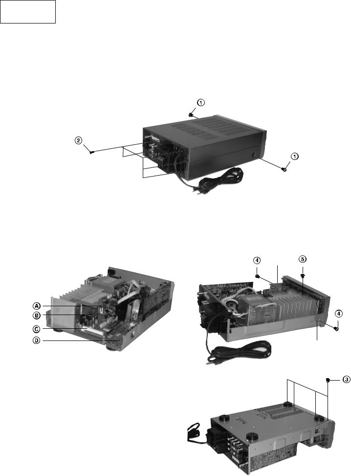
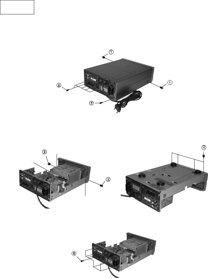
• AM-FM TUNER AMPLIFIER (HTA-R100)
1.Removal of Cover
(1)Remove 2 screws  from both sides.
(2)Remove 5 screws  from the rear plate.
2.Removal of Front Panel
(1)Remove 4 screws  from the bottom side of the front panel.
(2)Remove 2 screws  from both sides.
(3)Remove screw  to remove the ground wire. (E DEST ONLY).
(4)Remove the connectors  ,
,  ,
,  and
and  .
.
(5)Remove the Front Panel by releasing the pawl on both sides.
Pawl |
(E DEST ONLY) |
– 4 –
AX-F300
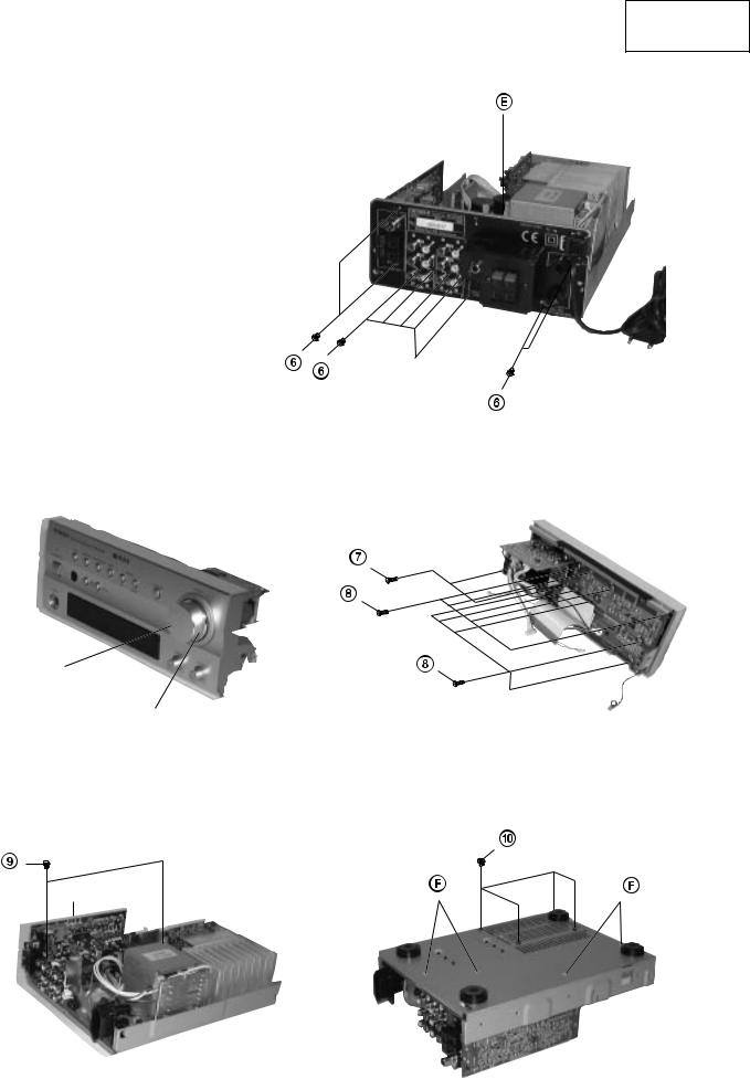
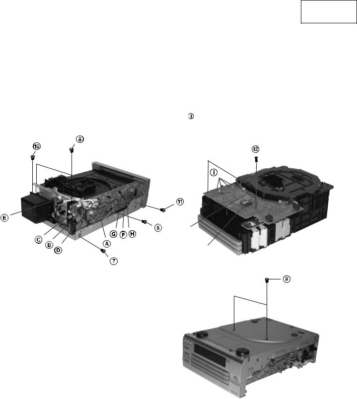
3. Removal of Rear Panel
(1)Remove 9 screws  from the rear panel.
(2)Remove the connector  .
.
4.Removal of Front P. W. Board
(1)Remove 2 screws  and then the tone P. W. board.
(2)Remove the volume knob assy, remove the nut and remove the volume P. W. board.
(3)Remove 9 screws  .
.
Con
N u t
5.Removal of Main P. W. Board
(1)Lift up the TU P. W. board and remove it from the main P. W. board.
(2)Remove 2 screws  from the top side of the main P. W. board.
(3)Remove 4 screws  from the bottom side of the chassis.
(4)Remove the 4 P. W. board holders  from the chassis via the bottom side of the chassis.
TU P. W. board
– 5 –
AX-F300
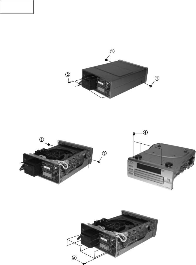
• CD CHANGER (DA-R100)
1.Removal of Cover
(1)Remove 2 screws  from both sides.
(2)Remove 3 screws  from the rear panel.
2.Removal of Front Panel
(1)Remove 2 screws  from both sides.
(2)Remove 3 screws  from the bottom side of the front panel.
(3)Remove the Front Panel by releasing the pawl on both sides.
(4)Remove the flat cable from the main P. W. board.
Pawl
3.Removal of Rear Panel
(1) Remove 7 screws  from the rear panel.
– 6 –
AX-F300
4.Removal of CD Mechanical-Unit Assembly, Main P. W. Board and Motor P. W. Board
(1)Remove one each of screws  and
and  from the main P. W. board on the side.
(2)Remove 2 screws  from the top side of the mechanical unit.
(3)Remove 2 screws  from the bottom side of the chassis.
(4)Remove the connectors  ,
,  ,
,  and
and  of the main P. W. board.
(5)Remove the connector  of the P. T. P. W. board.
(6)Remove 1 screw  from the top side of the P. T. cover and detach the power transformer from the chassis.
(7)Remove 1 screw  of the ground wire.
(8)Remove the connectors  ,
,  and
and  of the motor P. W. board from the main P. W. board.
(9)Remove 2 screws  from the motor P. W. board.
(10)Remove the solder from the four places of the soldering section of the motor. (11)Remove the connectors PG402 and 403 of the motor P. W. board.
P G 4 0 2
P G 4 0 3
– 7 –
AX-F300
• MINI DISC RECORDER (HMD-R50)
1.Removal of Cover
(1)Remove 2 screws  from both sides.
(2)Remove 6 screws  from the rear panel.
2.Removal of Front Panel
(1)Remove 2 screws  from both sides.
(2)Remove 4 screws  from the bottom side of the front panel.
(3)Remove the Front Panel by releasing the pawl on both sides.
(4)Remove the flat cable from the main P. W. board.
Pawl
F L AT
3.Removal of Rear Panel
(1) Remove 7 screws  from the rear panel.
– 8 –

AX-F300
4.Removal of MD Mechanical-Unit Assembly
(1)Remove 4 screws  .
.
(2)Remove the flat cable from the main P. W. board.
F L A T
C A B L E
I/O P. W. Board
5.Removal of Main P. W. Board
(1)Lift up the I/O P. W. board and remove if from the main P. W. board.
(2)Remove 6 screws  .
.
– 9 –
AX-F300
ADJUSTMENTS
Measuring Instruments Necessar y for Adjustments
•DC voltmeter
•Screwdrivers for adjustments
Before adjustments, perform the following setting in the receiver section (HTA-R100).
Note: Making adjustments without performing the following setting may result in damage of power transistors.
(1) |
Power switch |
: OFF |
(2) |
Volume knob |
: MIN |
(3) |
Function switch |
: AUX |
(4) |
Speaker |
: Open |
(5) |
VR502L/R |
: Minimum |
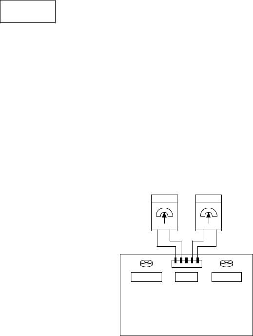
1.Idle Current Adjustment
(1)Connect the DC voltmeter to PG502. (Refer to the connection diagram.)
(2)Turn on the power and adjust VR502L (on the left) and VR502R (on the right) so that the measured value of the voltmeter can be within the range of 2 ± 0.5 mV.
DC Voltmeter |
DC Voltmeter |
||
– |
+ |
+ |
– |
VR502R PG502 VR502L
PRE AMP PWB
– 10 –
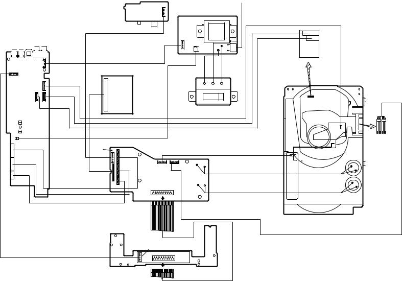
WIRING DIAGRAMS
• AM-FM TUNER AMPLIFIER (HTA-R100)
|
|
|
|
PWBTU |
|
|
|
|
|
|
|
|
CN101A |
|
|
|
|
|
|
|
|
|
|
|
|
|
|
|
|
|
|
PWB |
|
|
|
|
|
|
|
|
CN101B |
|
|
|
|
MAIN |
|
|
|
|
|
|
|
|
|
|
|
|
|
|
|
|
|
|
|
|
|
|
|
|
SPEAKERPWB |
|
|
|
|
|
|
CN505 |
|
|
|
CN502A |
|
|
|
|
|
|
|
|
|
|
|
|
|
||
|
|
|
|
|
|
P4A/P6A* |
|
P2A |
PG003 |
PG002 |
|
||
|
|
CN504 |
|
|
|
P9A |
|
|
|
PG504 |
|||
|
|
|
CN505 |
|
|
|
|||||||
|
|
|
|
|
|
|
|
* |
|
|
|
|
|
|
|
|
|
|
P3A |
|
* 10A |
|
|
|
|
|
|
|
|
|
|
W004(ORG) |
PG001 |
P2B |
* P8B |
W002(GRY) |
|
W010(YEL) |
W009(RED) |
|
|
VOLTAGE SELECTOR P.W.B |
(W/WUN ONLY) |
P10B P9B P8B |
P5B P6B P7B |
W006 W007 |
(BRN) (BRK) |
|
|
|
|
|
W005(ORG) |
W003(BLUE) |
* P4 B/ * P5A P3B P7A |
|
|
|
|
|
|
|
AP1 |
|
AC |
CORD |
|
|
|
|
PRE-AMP PWB |
|
PG503 |
CN502B |
CN501B |
|
|
PG301 |
|
CN103B |
W101 |
|
|
|
CN501A |
|
|
|
PG402 |
|
|
|
CN104B |
DISP PWB
CN003 |
PT PWB |
CN002 |
|
AX-F300
CN301 |
TONEPWB |
TERMINAL)(LUG |
PG401 |
|
|
|
W415 |
|
CN503 CN401 |
CN402 |
VOLUME PWB |
CN104A CN103A
W001
(LUG TERMINAL)
– 11 –
– 12 –
MAIN PWB
|
PG401 |
|
PG901 |
1 |
|
(W/WUN ONLY) |
||
|
||
1 |
|
PG101 |
1 |
|
|
1 |
1 |
PG102 PG103
1(PINK)
CN404 1
PG452
1
PG453
1
PG451
4P TXL CONN (W/WUN ONLY)
VIDEO PWB |
|
|
|
|
AP1 |
(W/WUN ONLY) |
|
|
|
|
|
|
|
|
|
AC CORD |
|
|
|
|
|
|
|
PG421 |
PT PWB |
|
|
|
|
1 |
|
|
|
|
|
5P TXL CONN |
|
W401A |
W403A |
PG001 |
W402A |
CN401 |
|
||||
|
|
|
|
|
|
|
PG404 |
|
|
|
|
1 |
1 |
|
|
|
|
(BRN) |
W401(BRN) |
W402(YEL) |
W403(RED) |
|
|
5P PH CONN |
|
|
|||
VIDEO MODULE |
|
|
|
|
|
(W/WUN ONLY) |
|
|
|
|
|
|
W401B |
W402B |
W403B |
|
|
1 |
|
|
VOL-SEL PWB |
|
|
6P MX CONN |
(W/WUN ONLY) |
|
|
|
|
|
|
8P PH CONN |
|
|
|
7P PH CONN |
|
|
|
2P TXL CONN |
|
(WN/WUN ONLY) |
|
|
|
CN421 |
1 |
|
5P MX CONN |
(BRN) |
|
CN452 |
|
|
|
||
|
1 |
1 |
1 |
|
|
||
|
1 |
PG403 |
PG402 |
|
|
CN453 |
(SOLDER) |
PG454 |
|
|
|
|
|
|
|
(WN/WUN ONLY) |
1 |
CN451 |
|
|
|
||
|
|
|
|
18P BTEM CONN |
|
PG801 |
(SOLDER) |
18P BTEM CONN |
|
||
|
|
1 |
|
8P BTEM CONN |
|
|
|
|
|
|
MOTOR PWB |
|
|
W101 |
6P MX CONN |
|
|
29P FFC CABLE |
|
|
|
|
|
|
|
|
3-DISC |
|
|
|
CHANGER |
CN901 |
FL PWB |
(WN/WUN ONLY) |
|
|
PG802 |
1 |
1 |
CD • |
F300-AX |
R100)-(DA CHANGER |
|
|
(BLK)
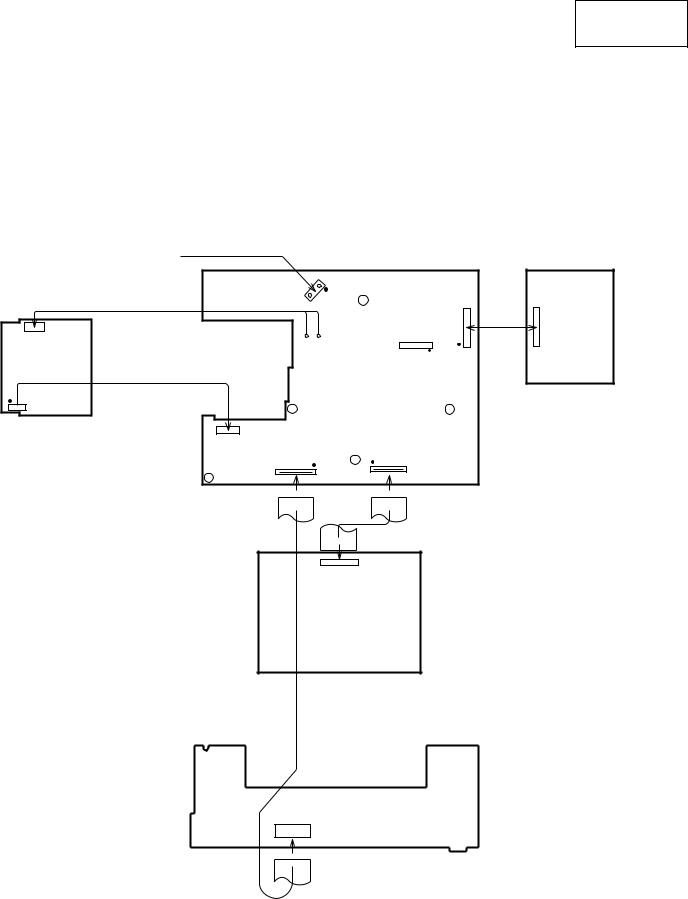
AX-F300
• MINI DISC RECORDER (HMD-R50)
 PG002
PG002
PT PWB
CN101
AC CORD
|
|
MAIN PWB |
I/O PWB |
|
PG001 |
|
|
CN002-2 |
CN002-1 |
|
B to B |
PG301 |
CN301 |
||
RED WHT |
CN501A |
|
|
|
|
||
 PG101
PG101
CN701B |
CN401 |
|
#073 #W201 28P FFC
CABLE
CN1501
MD MECHA UNIT
FL PWB
 CN701A
– 13 –
 Loading...