


HITACHI 4700 FE-SEM
COLD FIELD EMISSION |
2 |
STARTING CONDITIONS |
3-4 |
SPECIMEN LOADING |
5 |
SAMPLE INSERTION |
6-7 |
SAMPLE WITHDRAWAL |
7 |
SET IMAGE PARAMETERS |
8-10 |
OBTAINING AN IMAGE |
11 |
ALIGNMENT |
12 |
GENERAL OPERATION |
13-14 |
IMAGE ACQUISITION |
15 |
BACKSCATTER ELECTRON IMAGING |
16 |
COMPUTER STARTUP AND GUN FLASH PROCEDURE |
17-19 |
END OF DAY SHUTDOWN PROCEDURE |
20 |
Nils Hasselmo Hall EM Lab |
1 |
12/21/2011 |
WHY COLD FIELD EMISSION?
There are several benefits to cold field emission and few detractors. Cold Cathode Field Emission microscopy provides higher resolution, higher beam density (brightness), and longer tip life than Thermal Tungsten wire SEMs and thermally assisted “Schottky” field emitters. The following Table highlights those parameters responsible for the Cold Cathode Field Emission’s higher performance at lower accelerating voltages.
|
Source Diameter |
Energy Spread (eV) |
Brightness |
|
Thermal Tungsten |
50 |
– 100 kA◦ |
< 2.0 |
1 x |
Cold Cathode Field Emission |
30 |
– 50 A◦ |
0.2 |
1,000 x |
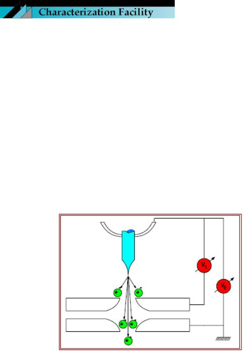
HOW DOES IT WORK?
The field emission tip is made up of a sharply etched piece of monocrystalline tungsten. A field is applied to the tip causing electrons to tunnel out of the tip and accelerate down the column. This is a basic diagram of the electron gun assembly in a field emission system. Notice that, in addition to the usual accelerating voltage anode (V0), a second voltage anode has been placed in close proximity to the FE tip. The desired accelerating voltage is obtained by adjusting Vo to accelerate or decelerate electrons emitted at the extraction voltage V1.
It is the ultimate combination of these two anode potentials which sets the final electron speed down the optical column. The computer automatically ratios these values for the operator.
Nils Hasselmo Hall EM Lab |
2 |
12/21/2011 |

STARTING CONDITIONS
1.EVAC POWER is ON (-)
2.DP/TMP, WATER, and AIR PRES lamps are
LIT (green)
3.IP-1, IP-2, and IP-3 lamps LIT (green).
4.OBJ. APT. switch is set at HEAT
5.Gun and Column MinimumVacuum
Levels:
IP-1 -- 1x10⁻⁸ Pa; IP-2 -- 1x10⁻⁷ Pa; IP-3 -- 5x10⁻⁶ Pa
6.Chamber Vacuums: Pe --
1x10⁻³ |
Pa; |
Pi’s: -- |
1x10⁻¹ |
Pa |
|
7.HIGH Lamps of S.C
Vacuum and S.E.C Vacuum are
LIT (green)
8.AUTO (OPEN) of GUN VALVE and OPEN of MV1 (EXCHANGE) VALVE FLASHING YELLOW
9.S.C./S.E.C toggle switch to S.E.C position. S.C. EVAC CHAMBER button LIT.
10.Specimen Bias Voltage (labeled VSP) cable CONNECTED
11.Infrared Chamber scope and Sony monitor ON.
12.Ensure that the BSE Detector is in the fully retracted (out of the column) position!!!
Nils Hasselmo Hall EM Lab |
3 |
12/21/2011 |
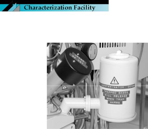
COLD FINGER (Optional)
The built-in anti-contamination cold finger, located on the right side of the specimen chamber, can be filled with liquid Nitrogen to reduce visible contamination on the specimen by collecting any grease, dirt, or impurities that can impede image observation, especially at high magnifications. The cold finger has a capacity of 0.9 L and is usable for nearly 5 hours once liquid Nitrogen is injected. Fill the Cold Finger with liquid Nitrogen. Pour in slowly at first and allow the trap to chill down for several minutes. Then add liquid Nitrogen until overflow occurs. It is important to maintain the trap fully cooled throughout
your session because trapped gases will release if warmed—increasing specimen contamination.
Nils Hasselmo Hall EM Lab |
4 |
12/21/2011 |
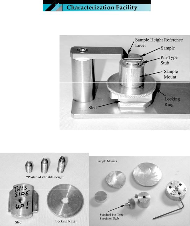
SPECIMEN LOADING (standard Hitachi stage; Hitachi specimen rod)
A sample mounted at the appropriate height is shown on the right.
The Sled is attached to the Specimen Exchange Rod; the Post connects the Sled to the Sample Mount of choice; the Locking Ring is tightened to secure the sample at the appropriate height.
There are a variety of Sample Mounts that fall into two categories: those to which the samples are attached directly; those
which accept the standard Pin-Type stubs.
Nils Hasselmo Hall EM Lab |
5 |
12/21/2011 |
SAMPLE INSERTION
1. |
Always check the sample height using the sample height gauge (if height exceeds the |
||||||
|
gauge, consult with staff). |
|
|
|
|
|
|
2. |
The Stage must be in the HOME position. Move the stage manually to the appropriate |
||||||
|
Home Settings in the Table below. Current Home Setting can be obtained from the |
||||||
|
“Stage Z Axis Setting Today” posting on the front of the column. |
|
|
||||
|
|
|
|
|
|
|
|
|
|
STAGE HOME POSITIONS |
|
|
|
||
Stage |
|
Rod |
Z (mm) |
Rotate (°) |
Tilt (°) |
X (mm) |
Y (mm) |
EMITECH cryo-stage |
EMITECH rod |
15 |
0 |
0 |
12.5 |
12.5 |
|
EMITECH cryo-stage |
HITACHI rod |
28.5 |
0 |
0 |
12.5 |
12.5 |
|
HITACHI stage |
HITACHI rod |
12 |
0 |
0 |
12.5 |
12.5 |
|
3. |
Make sure the High Voltage is OFF*; S.C./S.E.C toggle switch to S.E.C position; and |
||||||
|
the MV1 Chamber Valve is in the closed position. |
|
|
|
|||
*Consult “Computer Startup and Gun Flash Procedure” section if the computer/software is not on/open.
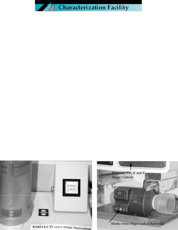
4. Ensure that the STAGE LOCK is OFF.
5.Hit the AIR button to vent the exchange chamber.
6.Pull the door open by grabbing the SEC unit, not the rod.
7.Push the Specimen Exchange Rod slightly to unlock it and screw the sample holder onto the end of the rod.
Nils Hasselmo Hall EM Lab |
6 |
12/21/2011 |
 Loading...