


IMPORTANT SAFEGUARDS
HITACHI
SOLID STATE COLOR TV
35TX59K, 35TX50B, 35TX30B
OPERATING GUIDE
Your new HITACHI COLOR TV incorporates a host of features designed to give you excellent performance if you follow the instructions in this manual. Please read the following instructions and "IMPORTANT SAFEGUARDS" notice before turning on your TV for the first time.
This television receiver will display television closed captioning ( or
or  ), in accordance with paragraph 15.119 of the FCC rules.
1

IMPORTANT SAFEGUARDS
TABLE OF CONTENTS |
|
IMPORTANT SAFEGUARDS................................................................................................................. |
3 |
POWER SOURCE................................................................................................................................ |
4 |
HOOK-UP CABLES AND CONNECTORS ........................................................................................ |
11 |
BEFORE OPERATING YOUR TV SET.............................................................................................. |
12 |
INSTALLATION .................................................................................................................................. |
12 |
ANTENNA CONNECTIONS (35TX59K AND 35TX50B) ................................................................. |
13 |
ANTENNA CONNECTIONS (35TX30B)............................................................................................. |
14 |
LOCATION OF CONTROLS ................................................................................................................ |
16 |
FRONT PANEL CONTROLS................................................................................................................ |
16 |
FRONT PANEL JACKS AND CONNECTIONS................................................................................. |
17 |
REAR PANEL JACKS ........................................................................................................................... |
18 |
REAR PANEL CONNECTIONS (35TX30B) ...................................................................................... |
19 |
REAR PANEL CONNECTIONS (35TX50B AND 35TX59K)........................................................... |
19 |
CONNECTING TO THE REAR SPEAKER TERMINALS............................................................ |
19 |
TIPS ON REAR PANEL CONNECTIONS...................................................................................... |
21 |
THE GENIUS REMOTE CONTROL (CLU-850GR).......................................................................... |
22 |
THE GENIUS REMOTE CONTROL (CLU-692GR with P-in-P) ..................................................... |
23 |
HOW TO USE THE GENIUS REMOTE TO CONTROL YOUR T.V.............................................. |
24 |
-SET UPFUNCTIONS ......................................................................................................................... |
27 |
PICTURE-IN-PICTURE (P-IN-P) FUNCTIONS................................................................................. |
35 |
P IN P BUTTON.................................................................................................................................. |
35 |
-PICTURE- FUNCTIONS ...................................................................................................................... |
37 |
AUDIO SYSTEM SET-UP..................................................................................................................... |
39 |
-SOUND- FUNCTIONS ......................................................................................................................... |
39 |
FOR 35TX30B ONLY......................................................................................................................... |
41 |
USING THE GENIUS REMOTE TO CONTROL VCR FUNCTIONS............................................. |
44 |
USING THE GENIUS REMOTE TO CONTROL CABLE BOX FUNCTIONS............................... |
45 |
USING THE GENIUS REMOTE TO CONTROL............................................................................... |
46 |
TABLE 1. VCR Precoded remote controls for Hitachi GR III Remote CLU-850GR. ............... |
46 |
TABLE 2. Cable Box Precoded remote controls for Hitachi GR III Remote CLU-850GR. ..... |
47 |
TABLE 3. VCR Precoded remote controls for Hitachi GJ III Remote CLU-692GR. ................ |
47 |
TABLE 4. Cable Box Precoded remote controls for Hitachi GJ III Remote CLU-692GR. ...... |
49 |
USING THE GENIUS REMOTE TO LEARN ADDITIONAL FUNCTIONS.................................... |
49 |
ACCESSORIES PART NUMBERS ..................................................................................................... |
52 |
REMOTE CONTROL BATTERY INSTALLATION AND REPLACEMENT ................................... |
52 |
TROUBLESHOOTING........................................................................................................................... |
54 |
RECEPTION PROBLEMS (EXTERNAL TO THE TV) ................................................................. |
54 |
CHECK HERE BEFORE CALLING FOR SERVICE..................................................................... |
55 |
SPECIFICATIONS ................................................................................................................................. |
56 |
HITACHI SERVICE HOTLINE.............................................................................................................. |
57 |
2

IMPORTANT SAFEGUARDS
IMPORTANT SAFEGUARDS
Follow all warnings and instructions marked on this television receiver.
CAUTION: TO REDUCE THE RISK OF ELECTRIC SHOCK,
DO NOT REMOVE COVER (OR BACK).
NO USER-SERVICEABLE PARTS INSIDE.
REFER SERVICING TO QUALIFIED SERVICE PERSONNEL.
 The lightning flash with arrowhead symbol, within an equilateral triangle, is intended to alert the user to the presence of uninsulated "dangerous voltage" within the product's enclosure that may be of sufficient magnitude to constitute a risk of electric shock to persons.
 The exclamation point within an equilateral triangle is intended to alert the user to the presence of important operating and maintenance (servicing) instructions in the literature accompanying the appliance.
WARNING:
TO PREVENT FIRE OR SHOCK HAZARD, DO NOT EXPOSE THIS TELEVISION SYSTEM TO RAIN OR MOISTURE.
NOTE: • There are no user serviceable parts inside the receiver.
• Model number and serial number are indicated on the back side of the set.
3

IMPORTANT SAFEGUARDS
POWER SOURCE
This Hitachi color TV is designed to operate on 120 volts 60 Hz, AC household current. Insert power cord plug into a 120 volt 60 Hz outlet.
NEVER CONNECT THE TV TO 50 Hz, DIRECT CURRENT, OR ANYTHING OTHER THAN THE SPECIFIED VOLTAGE.
CAUTION:
POWER SUPPLY CORD
TO PREVENT ELECTRIC SHOCK DO NOT USE THIS (POLARIZED) PLUG WITH AN EXTENSION CORD, RECEPTACLE OR OTHER OUTLET UNLESS THE BLADES CAN BE FULLY INSERTED TO PREVENT BLADE EXPOSURE.
• POLARIZED PLUG 
NOTE: Never remove the back cover of the set as this can expose you to very high voltages and other hazards. If the set does not operate properly, unplug the set and call your dealer or service shop.
HITACHI
SAFETY POINTS YOU SHOULD KNOW ABOUT
YOUR HITACHI TELEVISION RECEIVER
CAUTION:
*Read all of these instructions.
*Save these instructions for later use.
*Follow all warnings and instructions marked on the television receiver.
Our reputation has been built on the quality, performance, and ease of service of HITACHI television receivers.
Safety is also foremost in our minds in the design of these units. To help you operate these products properly, this section illustrates safety tips which will be of benefit to you. Please read it carefully and apply the knowledge you Obtain from it to the proper operation of your
HITACHI television receiver.
Please fill out your warranty card at once and mail it to HITACHI. This will enable HITACHI to notify you promptly in the improbable event that a safety problem should be discovered in your model of product.
4

IMPORTANT SAFEGUARDS
FOR YOUR PERSONAL SAFETY
1 This television set is equipped with a polarized alternating-current line plug (a plug having one blade wider than the other). This plug will fit into the power outlet only one way. This is a safety feature. If you are unable to insert the plug fully into the outlet, try reversing the plug. If the plug should still fail to fit, contact your electrician to replace your obsolete outlet. Do not defeat the safety purpose of the polarized plug.
2 When the power cord or plug is damaged or frayed, unplug this television set from the wall outlet and refer servicing to qualified service personnel.
3 Do not overload wall outlets and extension cords as this can result in fire or electric shock.
4 Do not allow anything to rest on or roll over the power cord, and do not place the TV where the
power cord is subject to traffic or abuse. This may result in a shock or fire hazard.
5 Do not attempt to service this television set yourself as opening or removing covers may expose you to dangerous voltage or other hazards. Refer all servicing to qualified service personnel.
6 Never push objects of any kind into this television set through cabinet slots as they may touch dangerous voltage points or short out parts that could result in a fire or electric shock. Never spill liquid of any kind on the television set.
7 If the television set has been dropped or the cabinet has been damaged, unplug this television set from the wall outlet and refer servicing to qualified service personnel.
8 If liquid has been spilled into this television set, unplug it from the wall outlet and refer
5
IMPORTANT SAFEGUARDS
service to qualified service personnel.
9 Do not subject your television set to impact of any kind. Be particularly careful not to damage the picture tube surface.
10 Unplug this television set from the wall outlet before cleaning. Do not use liquid cleaners or aerosol cleaners. Use a damp cloth for cleaning.
11-1 Do not place this television set on an unstable cart, stand, or table. The television set may fall, causing serious injury to a child or an adult, and serious damage to the appliance. Use only with a cart or stand recommended by the manufacturer, or sold with the television set. Wall or shelf mounting should follow the manufacturer's instructions, and should use a mounting kit approved by the manufacturer.
11-2 An appliance and cart combination should be moved with care. Quick stops, excessive force, and uneven surfaces may cause the appliance and cart combination to overturn.
PROTECTION AND LOCATION OF YOUR SET
12 Do not use this television set near water, for example, near a bathtub, washbowl, kitchen sink, or laundry tub, in a wet basement, or near a swimming pool, etc.
• Never expose the set to rain or water. If the set has been exposed to rain or water, unplug the set from the wall outlet and refer servicing personnel.
13 Choose a place where light (artificial or sunlight) does not shine directly on the screen.
14 Avoid dusty places, since accumulated dust inside the chassis may cause failure of
6
IMPORTANT SAFEGUARDS
the set when high humidity persists.
15 The set has slots, or openings in the cabinet for ventilation purposes, to provide reliable operation of the receiver, and to protect from overheating. These openings must not be blocked or covered.
•Never cover the slots or openings with cloth or other material.
•Never block the bottom ventilation slots of the set by placing it on a bed, sofa, rug, etc.
•Never place the set near or over a radiator or heat register.
•Never place the set in a "built-in" enclosure, unless proper ventilation provided.
PROTECTION AND LOCATION OF YOUR SET
16-1 If an outside antenna is connected to the television set, be sure the antenna system is protected against voltage surges and built up static charges, Section 810 of the National Electrical Code, NFPA No. 70-1975, provides information with respect to proper grounding of the mast and supporting structure, grounding of the lead-in wire to an antenna discharge unit, size of grounding conductors, location of antenna discharge unit, connection to grounding electrode, and requirements for the grounding electrode.
EXAMPLE OF ANTENNA GROUNDING
16-2 Note to CATV system installer: (Only for the television set with CATV reception) This reminder is provided to call the CATV system installer's attention to Article 820-40 of the NEC that provides guidelines for proper grounding and, in particular, specifies that the cable ground shall be connected to the grounding system of the building, as close to the point of cable entry as practical.
17 An outside antenna system should not be located in the vicinity of overhead power lines or other electrical lights or power circuits, or where it can fall into such power lines or circuits. When installing an outside antenna system, extreme care should be taken to keep from touching such power lines or circuits as contact with them might be fatal.
7

IMPORTANT SAFEGUARDS
18 For added protection for this television set during a lightning storm, or when it is left unattended and unused for long periods of time, unplug it from the wall outlet and disconnect the antenna. This will prevent damage due to lightning and power-line surges.
8

IMPORTANT SAFEGUARDS
OPERATION OF YOUR SET
19 This television set should be operated only from the type of power source indicated on the marking label. If you are not sure of the type of power supply at your home, consult your television dealer or local power company. For television sets designed to operate from battery power, refer to the operating instructions.
20 If the television set does not operate normally by following the operating instructions, unplug this set television set from the wall outlet and refer servicing to qualified service personnel. Adjust only those controls that are covered in the operating instructions as improper adjustment of other controls may result in damage and will often require extensive work by a qualified technician to restore the television set to normal operation.
21 When going on a holiday: If your television set is to remain unused for a period of time, turn the television set "off" and unplug it from the wall outlet.
IF THIS SET DOES NOT OPERATE PROPERLY
22 If you are unable to restore normal operation by following the detailed procedure in your operating instructions, do not attempt any further adjustment. Unplug the set and call your dealer or service technician.
23 Whenever the television set is damaged or fails, or a distinct change in performance indicates a need for service, unplug the set and have it checked by a professional service technician.
24 It is normal for some TV sets to make occasional snapping or popping sounds, particularly when being turned on or off. If the snapping or popping is continuous or frequent, unplug the set and consult your dealer or service technician.
9

IMPORTANT SAFEGUARDS
FOR SERVICING AND MODIFICATION
25 Do not use attachments not recommended by the television set manufacturer as they may cause hazards.
26 When replacement parts are required, be sure the service technician has used replacement parts specified by the manufacturer that have the same characteristics as the original part. Unauthorized substitutions may result in fire, electric shock, or other hazards.
27 Upon completion of any service or repairs to the television set, ask the service technician to perform routine safety checks to determine that the television is in safe operating condition.
10
HOOK-UP CABLES AND CONNECTORS
HOOK-UP CABLES AND CONNECTORS
Most video/audio connections between components can be made with shielded video and audio cables that have phono connectors. For best performance, video cables should use 75-Ohm coaxial shielded wire. Cables can be purchased from most stores that sell audio/video products. Below are illustrations and names of common connectors.
Before purchasing any cables, be sure of the output and input connector types required by the various components. Also make sure the cables are the correct length.
300-Ohm Twin Lead Connector |
"F" Type 75-Ohm Coaxial Antenna |
Connector |
|
This outdoor antenna cable must be |
For connecting RF signals (antenna or |
cable |
|
connected to an antenna adaptor |
TV) to the antenna jack on the television. |
(300-Ohm to 75-Ohm). |
|
Phono Connector |
S-Video (Super Video) Connector |
|
Used on all standard video and audio |
|
This connector is used on camcorders, |
VCRs, |
|
|
cables which connect to inputs and outputs |
and laser disc players with an S-Video |
|
feature |
|
|
located on the Television's front and rear |
in place of the standard video cable to |
|
produce |
|
|
jack panels. |
a high-quality picture. |
|
11

BEFORE OPERATING YOUR TV SET
BEFORE OPERATING YOUR TV SET
INSTALLATION
ANTENNA
Unless your TV is connected to a cable TV system or to a centralized antenna system, a good outdoor color TV antenna is recommended for the best performance. However, if you are located in an exceptionally good signal area that is free from interference, and multiple image ghosts, an indoor antenna may be sufficient.
LOCATION
Select an area where sunlight or bright indoor illumination will not fall directly on the picture screen. Also, be sure that the location selected allows free flow of air to and from the perforated back cover of the set.
To prevent damaging the TV, do not leave the set in a place where the temperature becomes too hot. For example, exposed to direct sunlight or near a heating device, etc.
VIEWING
This TV set may be viewed from any desired distance. Most viewers prefer a distance of three to six feet or more, depending on screen size, for maximum eye comfort.
12
ANTENNA CONNECTIONS (35TX59K AND 35TX50B)
ANTENNA CONNECTIONS (35TX59K AND 35TX50B)
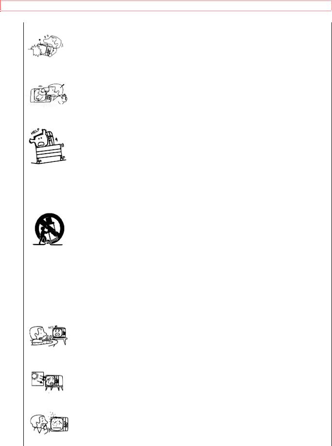
VHF (75-Ohm) antenna/CATV(cable TV)
When using a 75-Ohm coaxial cable system, connect the outdoor antenna or CATV coaxial cable to the VHF/UHF 75-Ohm terminal. If you have a second antenna or cable TV system, connect the coaxial cable to the AUX terminal.
REAR OF TV
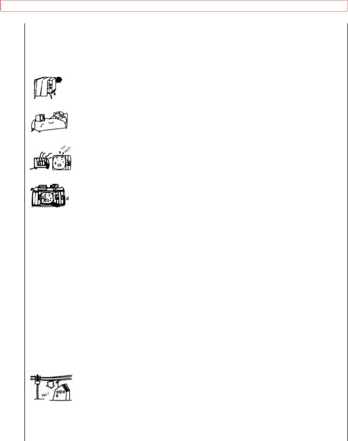
VHF (300-Ohm) antenna/UHF antenna
When using a 300-Ohm twin lead from an outdoor antenna, connect the VHF or UHF antenna leads to screws of the VHF or UHF adaptor. Plug the adaptor into the antenna terminal on the TV.
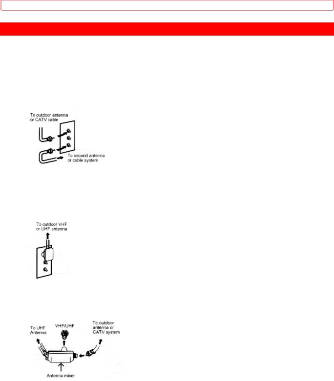
When both VHF and UHF antennas are connected
Attach an optional antenna cable mixer to the TV antenna terminal, and connect the cables to the antenna mixer. Consult your dealer or service store for the antenna mixer.
13

ANTENNA CONNECTIONS (35TX30B)
ANTENNA CONNECTIONS (35TX30B)
Your 35TX30B is equipped with one VHF/UHF antenna terminal. The VHF/UHF terminal can be used for normal TV, cable TV (CATV), or TV game, etc.
1. VHF (75 ) antenna/CATV
When using a 75-Ohm coaxial cable system, disconnect the VHF adapter from the 75 ohm receptacle and connect the outdoor antenna or CATV cable to a VHF 75 ohm
receptacle
2. VHF (300 ) antenna/UHF antenna
When using a 300-Ohm twin lead from an outdoor antenna, disconnect the (VHF or
UHF) indoor antenna leads from screws of the (VHF or UHF) adapter, and connect outdoor (VHF or UHF) antenna leads to these screws of a (VHF or UHF) adapter.
3. When both VHF and UHF antennas are connected
Attach an optional ANT. MIXER to the TV antenna terminal, and connect the cables to the ANT. MIXER.
Notes:
1.If an outdoor antenna/CATV is to be used, disconnect the indoor antenna. Do not leave both the indoor and outdoor antennas/CATV connected at the same time, since ghosting and poor reception may result.
2.Consult your dealer or service store for the ANT. MIXER and (VHF or UHF) adaptor.
14

ANTENNA CONNECTIONS (35TX30B)
3. The special converter (decoder) will be supplied by the cable company.
15

LOCATION OF CONTROLS
LOCATION OF CONTROLS
Front view illustration
Details are described by the number attached to the part name (example: 1).
1 AVX (Audio/Video) selector
Press this button to select the current antenna source, or video: 1, 2, or 3. Your selection is shown in the top right corner of the screen.
2 VOLUME level
Press these buttons for your desired sound level. The volume level will be displayed on the TV screen.
FRONT PANEL CONTROLS
CHANNEL selector
Press these buttons until the desired channel appears in the top right corner of the TV screen.
POWER button
Press this button to turn the TV on or off.
AI (Artificial Intelligence) sensor
This "Artificial Intelligence" sensor will make automatic picture adjustments depending on the amount of light in the room to give the best picture. See page 33.
REMOTE CONTROL sensor
Point your Genius Remote at this area when selecting channels, adjusting volume, etc.
FRONT INPUT JACKS (for VIDEO:3)
Use these audio/video jacks for a "quick" hook-up from a camcorder or VCR to instantly view your favorite show or new recording. (Press the AVX button until VIDEO:3 appears in the top right corner of the TV screen.)
NOTE: Your Hitachi TV will appear to be turned "off" if there is no video input when VIDEO:
16

FRONT PANEL JACKS AND CONNECTIONS
1, 2 or 3 is selected using the remote control AVX button. Check the Power On indicator to make sure the TV is off when not in use.
NOTE: Model 35TX30B is not equipped with an S-Video on the front input jacks (for
VIDEO:3) 7.
FRONT PANEL JACKS AND CONNECTIONS
• The front panel jacks are provided as a convenience to allow you to easily connect a camcorder or VCR as shown in tn the following examples.
Front panel jacks and connections illustration
NOTE:
•Completely insert the connection cord plugs when connecting to front panel jacks. If you do not, the played back picture may appear abnormal.
•If you have an S-VHS VCR, use the S INPUT cable in place of the standard video cable.
•Model 35TX30B is not equipped with front panel S-Video.
17

REAR PANEL JACKS
REAR PANEL JACKS
Click to see Rear Panel Jacks.
Antenna Inputs/Output
The "ANT" button on the Genius remote control allows you to switch between two separate 75-ohm RF antenna inputs, Main (VHF/UHF) and Auxiliar (AUX). The antenna output labeled "To converter" allows the main (VHF/UHF) antenna connection to pass directly to a different source such as a pay-TV cable decoder.
Audio/Video Inputs 1, 2
The "AVX" (Auxiliary video) button will step through each video source and the current antenna input each time it is pressed. Use the audio and video inputs to connect external devices, such as VCRs, camcorders, laser disc players, video games, etc.
Output
These jacks provide fixed audio and video signals which are used for recording.
Audio to Hi-Fi
These jacks provide variable audio output to a separate stereo system amplifier. With this connection, the audio to the stereo can be controlled by the television's remote control.
Rear Speaker Terminals
These terminals are used to connect external speakers, which are used for the surround sound feature. The volume level is controlled by the remote control main volume buttons and also by an independent rear volume feature found in the "sound" function menu. Use speakers with 8 impedance only. Terminals are switchable Internal/External Speakers.
S-Video
Input 1 provides S-Video (Super Video) jacks for connecting equipment with S-Video output capability.
NOTE: Model 35TX30B has only one antenna input and one external speaker output connection with an internal/external switch.
18
 Loading...