


HITACHI 50V720, 50VF820, 55VF820, 60VF820, 50VG825 Service Manual
...
January 2006 (ver a)
 HITACHI
PROJECTION TELEVISION
2006 MODEL RELEASE DIGITAL HD READY LCD
Model |
Chassis |
Remote |
P/N |
|
|
|
|
50V720 |
LC-57 |
CLU-4352UG2 |
HL02073 |
|
|
|
|
50VF820 |
LC-58 |
CLU-3842WL |
HL02062 |
|
|
|
|
55VF820 |
LC-58 |
CLU-3842WL |
HL02062 |
|
|
|
|
60VF820 |
LC-58 |
CLU-3842WL |
HL02062 |
|
|
|
|
50VG825 |
LC-58E |
CLU-3851WL |
HL02065 |
|
|
|
|
55VG825 |
LC-58E |
CLU-3851WL |
HL02065 |
|
|
|
|
60VG825 |
LC-58E |
CLU-3851WL |
HL02065 |
|
|
|
|
Service Web Site
http://www.hitachiserviceusa.com
CONTENTS... 2006 LC-5X Chassis Projection Television Information
Materials Prepared by… Alvie Rodgers C.E.T. (Chamblee, GA.)

LC-5X BLANK PAGE “USE FOR NOTES”
INTENTIONALLY LEFT BLANK

|
|
|
|
|
|
|
|
|
|
Materials prepared by |
|
|
|
January 2006 (ver a) |
|
LC-5X TABLE OF CONTENTS |
|
|
|||||||
|
|
|
Alvie Rodgers C.E.T. |
|
||||||||
|
|
|
|
|
|
|
|
|
|
|
||
|
|
|
|
|
|
|
|
|
|
|
|
|
|
|
|
|
TOPICS |
|
|
PAGE |
|
|
|||
|
|
|
|
|
|
|
|
|
|
|
|
|
|
|
|
|
SECTION (1) POWER SUPPLY DIAGRAMS: |
|
|
|
|||||
|
|
|
|
• Generic Power Supply Circuits Explained ------------------------------------ |
01-01 |
|
||||||
|
|
|
|
• A Out Shutdown Diagram --------------------------------------------------------- |
01-03 |
|
||||||
|
|
|
|
• B~E Out Shutdown Diagram ----------------------------------------------------- |
01-04 |
|
||||||
|
|
|
|
• F Out Shutdown Diagram --------------------------------------------------------- |
01-05 |
|
||||||
|
|
|
|
• F In Shutdown Diagram ----------------------------------------------------------- |
01-06 |
|
||||||
|
|
|
|
• 5V Standby Regulation Circuit Diagram ------------------------------------- |
01-07 |
|
||||||
|
|
|
|
• 5.6V Regulation Circuit Diagram ----------------------------------------------- |
01-08 |
|
||||||
|
|
|
|
• Power On Circuit Diagram ------------------------------------------------------- |
01-09 |
|
||||||
|
|
|
|
SECTION (2) VIDEO CIRCUIT INFORMATION: |
|
|
|
|||||
|
|
|
|
• Video Signal Selection Circuit Diagram ------------------------------------- |
02-01 |
|
||||||
|
|
|
|
SECTION (3) AUDIO CIRCUIT INFORMATION: |
|
|
|
|||||
|
|
|
|
• Audio Signal Selection Circuit Diagram ------------------------------------- |
03-01 |
|
||||||
|
|
|
|
• Audio Woofer Circuit Diagram -------------------------------------------------- |
03-02 |
|
||||||
|
|
|
|
SECTION (4) PWB PART NUMBERS AND REAR INPUTS: |
|
|
|
|||||
|
|
|
|
• LC-58 PWB Part Numbers ------------------------------------------------------- |
04-01 |
|
||||||
|
|
|
|
• LC-58E PWB Part Numbers ----------------------------------------------------- |
04-02 |
|
||||||
|
|
|
|
• LC-57 PWB Part Numbers ------------------------------------------------------- |
04-03 |
|
||||||
|
|
|
|
• LC-57 and LC58 Rear Inputs --------------------------------------------------- |
04-02 |
|
||||||
|
|
|
|
SECTION (5) THINGS YOU SHOULD KNOW: |
|
|
|
|||||
|
|
|
|
• See the index for this section after the Section 5 Divider. |
---------------- 05-00 |
|
||||||
|
|
|
|
|
|
|
|
|
|
|
|
|
Table of Contents Page 1

LC-5X BLANK PAGE “USE FOR NOTES”
INTENTIONALLY LEFT BLANK

POWER SUPPLY INFORMATION
LC-5X
CHASSIS INFORMATION
 SECTION 01

LC-5X BLANK PAGE “USE FOR NOTES”
INTENTIONALLY LEFT BLANK

LC-5X GENERIC POWER SUPPLY SHUTDOWN EXPLANATION
GENERIC POWER SUPPLY SHUTDOWN INFORMATION:
The Protect Circuit has been broken down into 4 distinct Sections. The input/outputs are identified by letters in circles (A) ~ (F). These Circuits are involved in the Shutdown inputs which shuts off the Power Supply in the LC-5X Chassis.
UNDERSTANDING SYMBOLS ON THE DIAGRAMS:
(Sheet 13)
In the case of the LC-58 Chassis, the Schematics are shown between pages 129 ~ 151. This represents 23 individual pages within the Service Manual PA-0210. To help identify the location of particular drawings, you will notice comments like “Sheet 13”. In this case, the diagram is taken from the 13th page of the Schematics shown in the Service Manual .
(17)
On the Power Supply Shutdown circuit diagrams you will notice small number at different locations along the shutdown path. The small numbers represent the number of shutdown “events” that are possible at this point in the circuit. As the lines continue, the numbers will grow and they are cumulative.
To help with Inputs and Outputs from the distinct Sections of the drawings, Symbols as shown on the left are used. This will help the Technician navigate between drawings more easily.
GENERIC SHUTDOWN CIRCUITS EXPLAINED:
The following circuits are commonly used in Hitachi LCD product and relate to the drawings used for Shutdown:
VOLTAGE TOO HIGH DETECTION
(See Figure 1)
This circuit is the Voltage Too High Detection circuit. In the example shown in Figure 1, the zener diode Z01 is connected to a voltage divider R01 and R02. If the voltage source rises too high, the voltage at the divider center point will rise as well and trigger or fire the zener diode which produces a Shutdown signal through D02 and on to the appropriate circuit.
VOLTAGE LOSS or SHORT DETECTION
(See Figure 2)
One circuit used is the Voltage Loss or Short Detection circuit. This is a very simple circuit that detects a loss of a particular power supply and supplies a Pull-Down path for the base of a PNP transistor Q1. This circuit consist of a diode connected by its cathode to a positive B+ power supply. Under normal conditions, the diode is reversed biases, which keeps the base of Q1 pulled up, forcing it OFF. However, if there is a short or excessive load on the B+ line that’s being monitored, the diode in effect will have a LOW on its cathode, turning it ON. This will allow a current path for the base bias of Q1, which will turn it ON and generates a Shutdown Signal.
|
|
Any Power Supply |
Z01 |
R01 |
Voltage Too |
|
|
|
|
R02 |
High Detector |
D02 |
|
|
|
Shutdown |
|
|
|
|
|
|
Signal |
|
Figure 1 |
|
|
Any Positive |
|
Voltage |
B+ Supply |
|
B+ |
||
Loss |
||
Detector |
Q1 |
|
|
||
Figure 2 |
Shutdown Signal |
(Continued on next page)
PAGE 01-01

LC-5X GENERIC POWER SUPPLY SHUTDOWN EXPLANATION
GENERAL INFORMATION:
This explains the Overall Power Supply Shutdown Circuits: Which turns off the Relay Drivers Q942, Q943 and Q944.
There are Four Relays which are activated when Power 1 and Power 3 go high. These Relays are all protected (turned off) by the 17 possible shutdown inputs.
•RELAY S901 Controlled by Power 3 to Transistor Q942:
This relay supplies AC to Relay S902 and S903 explained below.
•RELAY S902 Controlled by Power 1 to Transistor Q943:
This relay supplies AC to the Signal Power supply Bridge Rectifier D902.
•RELAY S903 Controlled by Power 3 to Transistor Q944:
This relay supplies AC to the Lamp Power PWB.
•RELAY S904 Controlled by Power 3 to Transistor Q944:
This relay supplies B+ to the Audio Circuit.
Q980 and Q981 Relay Inhibit Activation. (SHUTDOWN) called COMMON ACTION CIRCUIT.
All 17 Shutdown events will cause the above mentioned relays to turn off. This action will stop all secondary power supplies.
See the LC-5X Protect (F In) Shutdown Circuit for details.
If any of the shutdown circuits activate, the base of Q980 will go High. This turns on Q980 and removes the Power On Highs from PPT3 connector pins 6 and 2 called Power_1 and Power_3. With this, the main power supplies will STOP. Q981 operates as a “latch”. This prevents Q980 from turning off if the shutdown signal disappears after shutdown.
SOME SHUTDOWN CIRCUITS ARE DEFEATED IN STANDBY MODE. (Set Off).
When the set is turned off (called Stand By), some of the shutdown inputs are not active because the voltages being monitored are not on.
SHUTDOWN INPUTS EXPLAINED:
GENERAL INFORMATION CONTINUED: (See previous page for generic shutdown circuit details):
All of the Power Supply Shutdown circuitry can be broken down into the following categories;
•Voltage Missing Detection or Short Detection
•Voltage Too High Detection
Note: The Fan failure or “Stopped” alarms work the same as voltage too high detection. Normally when a fan is running, the pull-up resistor attached to the Fans B+ will not be allowed to pull up high due to the Fans internal Hall element’s action when the Fan is rotating. If the fan stops, the Pull-Up resistor will pull the shutdown signal “Alarm” up high. (See (B~E Out) Protect shutdown diagram).
The Door open signal works the same. A mechanical switch is located in such a fashion that when the door is closed, the switch is activated. This in turn pulls the door alarm voltage low and will not allow an “Alarm” to be generated as long as the door is closed. (See (B~E Out) Protect shutdown diagram).
Lamp Alarm. A mechanical switch is located in such a fashion that when the Lamp is installed, the switch is activated. This in turn pulls the door alarm voltage low and will not allow an “Alarm” to be generated as long as the Lamp is installed and the Lamp door is closed. (See (B~E Out) Protect shutdown diagram).
Temp Sensor. The Temperature sensor is normally in a state of Low Ohms. This prevents the Pull Up resistor from generating a Temperature Alarm. If the Fan Duct gets too hot, the Temperature Sensor resistance goes up and the Temperature alarm is generated. (See (A Out) Protect shutdown diagram).
PAGE 01-02
LC-5X (A Out) PROTECT SHUTDOWN DIAGRAM
Drive Sheet 15
The Protect Circuit has been broken down into 4 distinct Diagrams. The input/outputs are identified letters in circles (A) ~
(F). This Circuit begins the Shutdown input which shut off the Power Supply in the LC-58 Chassis. The Schematic are shown on 23 pages within the Service Manual PA-0210. This section is taken from the Drive Circuit on the 15th page of the Schematics shown in the Service Manual .
+5.6V
2 |
I801 |
4 |
3.8V |
D801
1 |
I804 |
8 |
+3.3VM |
3 |
|
7 |
|
D806
2 |
I808 |
4 |
+3.3V |
|
|
|
|
D805 |
|
From D801 Anode Monitors +3.8V from I801 Pin 4 |
|
|
|||
From D805 Anode Monitors +3.3V from I808 Pin 4 |
|
|
|||
From D806 Anode Monitors +3.3VM from I804 Pin 7 and 8 |
|
||||
|
|
|
|
See (B~E out) Protect |
|
|
|
Drive Sheet 19 |
Shutdown Diagram |
||
|
|
|
|
||
|
|
|
|
PDT |
|
|
Temp Sensor normally Low Ohms (Closed). |
|
|||
|
High Temp High Ohms (Open). |
10 |
PROT DRV |
||
|
|
|
|
PROT SW |
Normal |
|
SBY +5V |
|
|
||
|
|
|
A |
||
|
PDE |
|
R6M7 |
|
Active |
|
R6D1 |
R6M1 |
0 Ohm |
R688 |
|
|
TEMP_ALARM |
||||
|
2 |
Q604 |
|
9 |
|
|
R602 |
|
|
|
|
|
|
|
|
|
|
Temp |
3 |
|
|
|
|
Sensor |
|
|
|
|
|
On Lamp |
R6M0 |
R6M6 |
|
|
|
Housing |
|
|
|
||
|
|
0 Ohm |
|
|
|
|
|
|
|
|
PAGE 01-03 |

|
LC-5X (B~E Out) PROTECT SHUTDOWN DIAGRAM |
||||||||
|
|
|
Fan Sheet 13 |
|
|
RF28 |
|
|
|
|
|
|
|
|
Sby +5v |
PTW1 |
|||
|
|
1 |
|
|
|
||||
E |
DooR |
|
|
|
|
|
1 |
To Door Sw PWB |
|
|
|
|
|
|
|
on Control |
|||
Alarm |
|
|
|
|
|
|
|||
|
|
|
DF08 |
|
RF29 |
|
|
Sheet 22 |
|
|
|
QF01 |
|
|
|
|
|||
|
Fan |
|
|
|
|
|
|
||
|
|
|
|
CF15 |
DF07 |
|
|
|
|
|
Prot |
|
|
|
|
PFA1 |
|
||
|
|
|
|
|
DF05 |
|
|
For Optical Engine |
|
D |
Fan |
4 |
|
|
|
|
1 |
Fan Alarm |
|
|
|
|
|
|
|
||||
Alarm |
|
|
|
|
RF39 |
|
|||
|
|
|
|
|
|
|
|
||
|
|
|
|
|
Fan 12V |
|
2 |
Fan +10V |
|
|
|
|
|
|
|
|
|||
|
SW +16.5V |
5 |
IF02 |
3 |
|
|
|
3 |
Fan Gnd |
|
|
|
|
|
DF03 |
|
|
PFA3 |
For Lamp |
To DM/Power I/F |
|
2 |
|
|
|
|
|
||
|
Sheet 11 |
|
|
|
|
|
1 |
Fan Alarm |
|
|
|
|
|
|
|
RF41 |
|
||
See (F Out) |
|
|
|
|
|
2 |
Fan +10V |
||
|
|
|
|
|
|
||||
|
Protect |
|
|
|
|
|
|
||
|
|
|
|
|
|
|
|
|
|
Shutdown |
|
|
|
|
|
|
3 |
Fan Gnd |
|
|
Diagram |
|
|
|
|
|
|
||
|
|
|
|
|
|
|
|
|
|
|
|
|
|
|
DF01 |
|
|
PFA4 |
For Chassis |
|
Power |
|
|
|
|
|
1 |
Fan Alarm |
|
|
|
|
|
|
|
|
|||
|
3 |
|
|
|
|
RF42 |
|
|
|
|
|
|
|
|
|
|
2 |
Fan +10V |
|
|
|
|
|
|
|
|
|
||
|
|
|
|
|
|
|
|
3 |
Fan Gnd |
|
|
|
|
|
DF04 |
|
|
PFA6 |
For Digital Module |
|
|
|
|
|
|
|
1 |
Fan Alarm |
|
|
|
|
2 |
|
|
RF38 |
|
||
|
|
|
|
|
|
|
|
||
|
|
5 |
IF03 |
3 |
Fan 10V |
|
2 |
Fan +10V |
|
|
|
RF34 |
|
||||||
|
|
|
|
|
|
|
3 |
Fan Gnd |
|
|
|
|
|
|
|
0 Ohm |
|
||
|
|
|
RF26 |
|
|
|
|
PDT |
|
C |
Temp |
1 |
|
|
|
1 |
9 |
TEMP ALARM |
|
|
|
|
|
||||||
Alarm |
|
|
|
|
|
|
|||
|
|
|
|
|
|
|
|
To Drive Sheet 15 |
|
|
Prot |
|
RF27 |
|
|
|
|
|
|
B |
|
|
|
|
3 |
10 |
PROT SW |
||
|
|
|
|
|
|||||
DRV |
3 |
|
|
|
|
|
|||
|
|
|
|
|
|
|
A |
||
|
|
|
|
|
|
|
|
||
|
|
|
|
|
|
See (A) Protect |
|||
|
|
|
|
|
|
|
|||
|
|
|
|
|
|
Shutdown Diagram |
|||
PAGE 01-04
|
LC-5X (F Out) PROTECT SHUTDOWN DIAGRAM |
|
||||||
Fan +10V |
Fan +12V |
|
|
|
|
See (B~E) Fan Protect |
||
|
|
B |
PRoT |
|
|
|||
|
|
To Fan Drive |
|
|
Circuit Diagram |
|||
|
|
|
DRV |
Sheet 13 |
|
To Fan Drive Sheet 13 |
||
|
|
|
|
|
||||
|
|
|
|
|
|
|||
|
|
|
|
|
|
DooR |
Temp |
Fan |
RJ32 |
RJ34 |
|
|
|
|
Alarm |
Alarm |
Alarm |
|
4 |
|
|
1 |
1 |
4 |
||
|
|
|
|
|
||||
|
|
|
DJ04 |
DJ23 |
DJ25 |
E |
C |
D |
DJ16 |
|
|
|
|
|
|||
DJ22 |
|
|
|
|
|
|
|
|
DJ15 |
|
|
RJ31 |
|
|
RJ05 |
RJ06 |
RJ07 |
|
|
DJ21 |
|
|
||||
|
|
|
|
|
|
|
|
|
|
|
|
DJ17 |
DJ18 |
DJ00 |
|
DJ01 |
|
|
RJ3O |
CJ08 |
|
|
|
|
1 |
5 |
QJ06 |
|
|
|
|
|
|
||
|
|
|
5 |
|
|
|
|
|
|
|
|
|
|
|
|
|
|
|
DJ15 |
|
|
|
|
|
6 |
|
|
|
|
|
|
|
|
|
|
5 |
11 |
See (F In) Protect |
|
Shutdown Circuit Diagram |
To Power |
for Continuation. |
Sheet 20 |
|
|
PPT3
Active
Normal
7 |
F |
15 |
< Protect > |
Sig + 5.6V |
Sig + 10.5V |
Sig + 16.5V |
4
|
DJ08 |
RJ08 |
RJ10 |
DJ11 |
|
|
CJ04 |
|
|
QJ02 |
RJ17 |
|
|
|
|
|
|
1 |
|
|
|
|
|
|
|
|
|
DJ07 |
DJ10 |
RJ18 |
Sig +10.5 & 16.5 V |
|
16.5 V Too High |
|
|
Loss Detection |
|
Detection |
|
|
|
|
|
|
RJ19 |
|
CJ03 |
|
|
DJ09 |
|
|
|
|
|
|
|
|
3 |
|
|
|
DM/POWER/I/F Sheet 11 |
|
PAGE 01-05

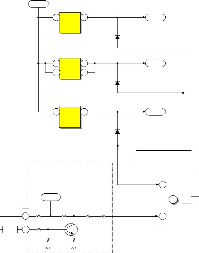
LC-5X PROTECT (F In) SHUTDOWN CIRCUIT
06-01 PAGE
From Sub |
From Digital |
|
|
|
See Protect (F Out) |
|
|
|
Micro |
Module |
|
|
|
|
|
|
|
|
|
|
|
Shutdown Circuit Diagram |
|
|||
Pin 20, Q021, Q025 |
Pin 81 |
|
|
|
|
|
||
PPT3 |
Audio Vcc |
for Inputs. |
F |
|
||||
Power 1 |
Power 3 |
|
||||||
6 |
2 |
|
11 |
12 |
13 |
|
7 |
15 |
off on |
off |
on |
|
|
|
|
<PROTECT> Active |
|
|
|
SBY +5V |
|
|
Raw B+ |
F903 |
|
Normal |
|
|
|
|
|
|
4 |
|
|
|
SBY +5V |
R946 |
R947 |
|
|
S901 |
|
AC |
|
D902 |
R924 |
|
|
|
|
|
|
|
|
|
|
|
|
|
|||
|
|
|
|
|
|
|
|
|
2.2 ohm |
|
|
|
|
From S901 |
AC |
|
|
|
|
|
D940 |
|
F904 |
|
|
|
|
For |
|
S902 |
|
|
|
|
Q942 |
|
For |
AC |
AC |
R925 |
|
|
|
|
D958 |
D944 |
|
|
|
||||||
Signal |
|
D941 |
R944 |
|
|
|
S902 |
|
|
|
6 |
||
Power |
|
|
|
|
|
Relay |
S903 |
|
|
|
|||
Supply |
|
|
D946 |
|
R943 |
R940 |
|
|
|
|
T902 |
||
D902 |
|
|
|
Driver |
|
|
|
||||||
|
|
|
|
|
|
|
|
||||||
Q943 |
|
D945 |
SBY +5V |
|
|
|
|
|
Hot |
D915 |
|
||
|
|
|
|
|
|
|
|
|
|
|
9V |
(8.9V ~ 9.3V) |
|
Relay |
|
|
|
|
|
|
|
|
|
Ground |
|
||
|
|
|
S903 |
|
From S901 |
|
|
|
|
|
|||
|
|
|
|
Audio B+ |
|
|
|
R926 |
|||||
Driver |
|
|
|
|
|
|
|
||||||
R941 |
|
|
|
|
AC |
|
|
|
|||||
|
|
|
|
|
2.2 ohm |
S904 |
|
|
|
R927 |
|
||
|
|
|
|
|
|
|
|
|
|
|
|
||
|
|
|
|
|
|
|
F904 |
|
Audio |
|
|
|
|
|
|
|
|
|
|
|
PPT3 |
|
Vcc |
|
|
C916 |
|
|
|
|
|
D942 |
|
|
3 |
D943 |
|
AC 175 On |
|
||
|
|
|
|
|
|
|
|
|
|||||
|
|
|
|
|
|
|
|
|
|
|
|||
Power |
|
To Lamp Power |
|
|
Q901 |
|
I905 |
SBY 5V |
|
|
|
|
|
Sig +10.5V |
|
|
|||
Sheet 20 |
R945 |
|
|
Q944 |
|
|
|||
|
|
|
|
2 |
|
|
4 |
||
|
|
|
|
|
|
|
|||
|
|
|
|
Relay |
|
|
|
||
|
D951 D947 D948 |
R942 |
|
I902 |
|
|
|
||
D950 |
Driver |
Run B+ 19V |
|
|
|
||||
R980 |
C980 |
Q981 |
|
|
D988 |
|
1 |
|
3 |
|
|
|
|
|
|
|
|
||
Q980 |
|
R982 |
|
D990 |
R923 |
D959 |
1 |
||
|
|
|
|
|
1 |
|
|
|
|
|
|
|
|
|
|
|
|
15 |
|
|
|
R981 |
17 |
|
Excessive Sig +10.5V |
AC Voltage Too High |
|||
|
|
C981 |
|
|
Voltage Detection |
|
Detection |
||

LC-5X (STB 5V) Stand By Power Supply
|
D901 |
|
F902 |
|
|
T901 |
+7.5V |
|
|
+ |
|
|
D949 |
||||
AC |
- |
|
|
|
|
|
1 |
|
|
|
|
|
|
|
|
||
|
|
|
C908 |
|
|
|
C940 |
|
|
|
|
|
5 |
|
|
||
|
|
|
|
|
|
|
|
|
|
|
|
3 |
|
I901 |
7 |
|
|
|
|
|
|
|
|
8 |
|
|
|
|
|
|
1 |
4 |
2 |
|
|
|
|
|
|
|
|
D906 |
R906 |
|
|
|
|
|
|
|
C912 |
|
|
|
R908 |
R908 |
R908 |
|
|
|
|
|
|
|
|
|
|
|
|
I904 |
R957 |
|
|
|
|
|
|
|
4 |
|
|
|
|
|
|
|
|
1 |
|
|
|
C911 |
|
|
|
D907 |
|
R958 |
|
|
|
|
|
5.6V |
|
|
|
|
|
|
|
|
|
3 |
2 |
|
|
|
|
|
|
|
|
||
|
|
|
|
|
|
|
|
D962 |
|
|
|
|
|
|
|
|
6.8V |
|
|
|
|
|
|
Power |
|
|
|
|
|
|
|
|
Sheet 20 |
|
|
|
|
PPT2 |
|
I942 |
3 |
17 |
SBY +5V |
2 |
C957 |
|
|
|
|
|
PAGE 01-07

|
LC-5X CHASSIS POWER SUPPLY SIGNAL 5.6V REGULATION |
|
|||||||||
1 of 3 |
|
|
|
|
|
|
|
|
|
|
|
T902 |
7.5P/P |
|
|
|
|
|
Power |
|
|
|
|
9 |
|
|
|
|
|
|
|
|
|
||
|
|
|
|
|
|
|
|
|
|
||
|
|
|
|
|
|
Sheet 20 |
|
|
|
|
|
|
|
|
|
|
|
|
|
|
|
Sig +10.5V |
|
|
D913 |
C925 |
|
|
|
|
|
|
|
|
|
11 |
|
|
D914 |
|
Hot Ground from negative |
|
|
||||
|
|
|
|
|
|
||||||
|
|
|
|
|
|
|
side of bridge rectifier D902 |
FB |
R963 |
||
|
|
|
|
|
|
|
|
|
|
||
From LP06 pin 4 |
|
|
Run |
|
|
|
|
I906 |
|
||
Supplied from Relay S903 |
|
|
|
|
|
|
|
|
8.6V |
||
|
|
|
|
|
|
|
|
|
3 |
|
1 |
C926 |
|
D910 |
19.3V |
9 |
|
|
|
4.4V |
|
R964 |
|
|
|
|
|
4 |
|
||||||
|
|
|
|
|
Vcc |
|
|
|
|
2 |
|
|
|
|
|
|
10 |
|
|
2.1V |
|
7.6V |
|
|
D909 |
|
|
|
OCP/FB |
|
|
|
|
||
|
|
|
|
|
R921 |
|
|
|
|||
1/2 AC |
Start Up |
5 |
|
|
|
R922 |
C930 |
Regulator |
|
||
|
|
|
|
|
|
||||||
|
|
|
|
|
|
|
|||||
|
|
C933 |
|
|
I902 |
17 |
|
|
Photocoupler |
|
|
AC Supplied from |
|
|
C929 |
|
|
|
|
||||
|
1 |
Driver/ |
18 |
|
|
|
|
||||
Relay S902 |
|
Output IC |
|
|
|
|
|
||||
|
|
|
|
|
|
|
|
||||
Raw B+ from D902 |
163.6V |
20 |
D |
S |
11 |
R962 |
R961 |
C950 |
|
|
|
150V |
2 of 3 |
|
21 |
|
|
|
|
|
|||
|
|
|
|
|
|
|
|
|
|||
|
|
|
|
|
|
|
|
|
|
|
|
|
T902 |
|
|
|
|
|
|
|
3 |
|
|
|
4 |
|
|
|
R916 |
|
Sig +5.6V |
7.6V |
|
||
F903 |
|
|
|
|
I941 |
|
|
||||
|
|
|
|
R917 |
|
|
|
|
|
||
|
|
|
|
|
R918 |
|
|
|
1 |
|
|
|
|
|
|
|
|
|
|
|
|
|
|
|
All 0.47 |
|
2.4V |
|
|
|
R966 |
2 |
|
6 |
|
|
||
|
|
|
3 of 3 |
10K |
PPT2 |
|
T902 |
|
||
16 |
E942 |
4.59A |
|
Sig +5.6V |
1 |
|
|
|
|
||
|
1 |
2 |
|
15 |
D955 |
|
|
14 |
2 |
3 |
|
C948 |
|
|
|
|
4 |
Sig +5.6V |
|
|
3 |
||
|
|
|
|
|
|
5 |
|
|
|
6 |
|
|
|
7 |
|
|
Cold Ground from pin |
|
|
|
14, 17, 20 of T902 |
|
|
PAGE 01-08
 Loading...