

Page 1
User’s Manual
CNC PILOT 620
CNC PILOT 640
NC Software
688945-03
688946-01
688947-01
English (en)
8/2013
Page 2
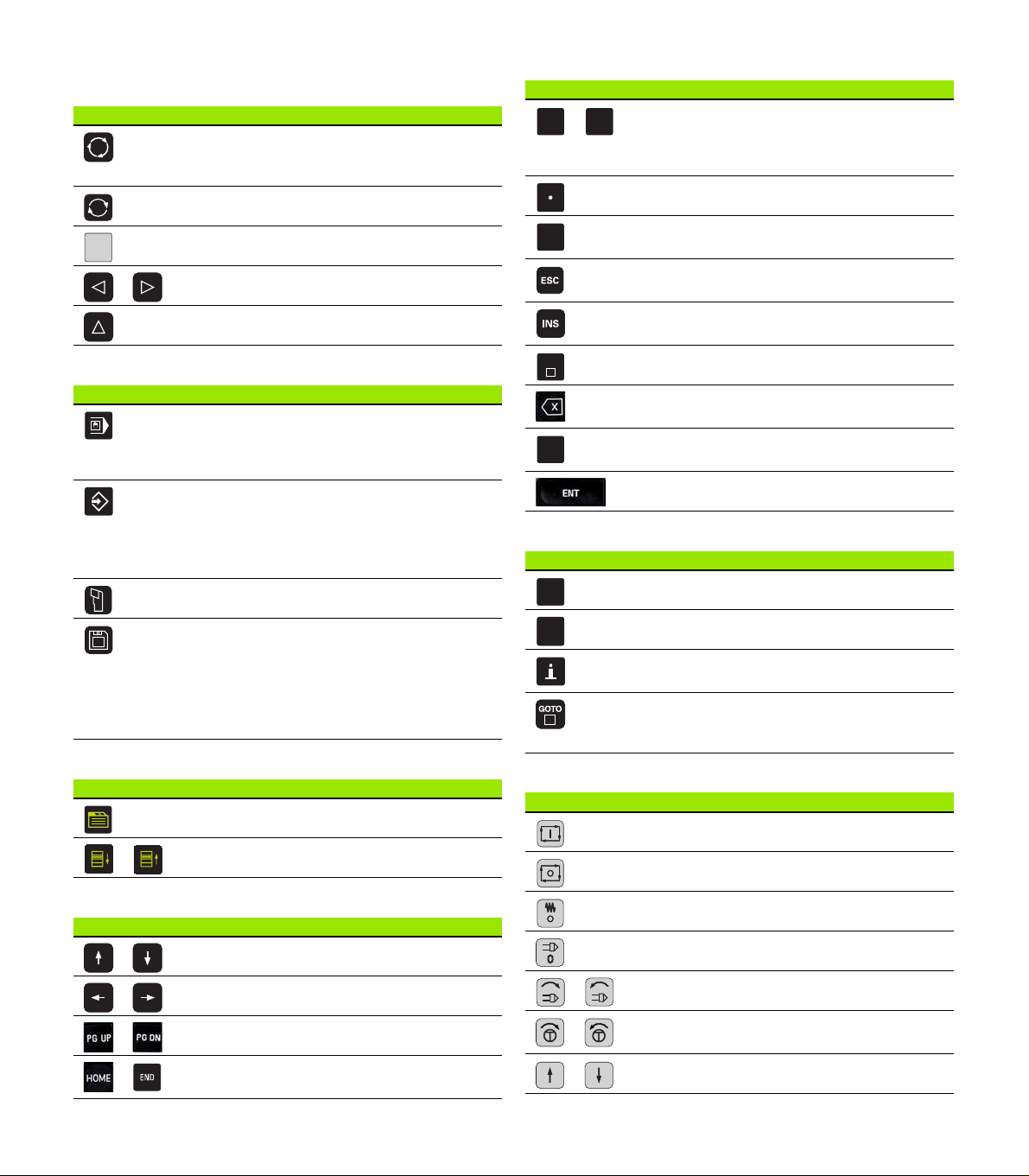
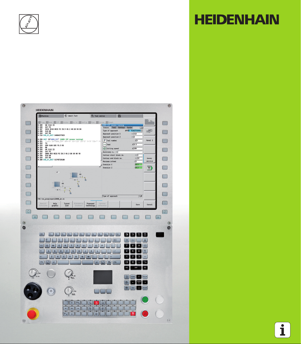
Controls and displays of the CNC PILOT
0
9
+
/
DEL
CE
ERR
CALC
Keys on visual display unit
Key Function
Switches the help graphics between outside
and inside machining (only in the cycle
programming)
No function
Soft keys for selecting functions on screen
Switches to the soft-key menu at left / right
Switches to the next menu in the PLC menu
Operating mode keys
Key Function
Machine operating modes:
Manual Operation
Program Run
Programming modes
smart.Turn
DINplus
DIN/ISO
Tables for tool data and technology data
Numeric keypad
Key Function block
Number keys 0-9:
Numeric input keys
Menu operation
Decimal point
Switchover between positive and negative
values
Escape key: Cancelation of dialogs and next
higher menu level
Insert key: OK in dialogs and new NC blocks
in the editor
Delete block: Deletes the selected area
Backspace: Deletes the character to the left
of the cursor
CE key: Deletes the error messages in the
machine operating mode
Enter: Confirms the input
Special keys
Key Function
Error key: Opens the error window
Organization:
Parameters
File organization
Transfer
Diagnosis
smart.Turn keys
Key Function
Go to the next form
Next/previous group
Navigation keys
Key Function
Up/Down arrow keys
Left/Right arrow keys
Screen page or dialog page up/down
Go to beginning of program/list or to end of
program/list
Starts the integrated calculator
Info key: Shows additional information in the
parameter editor
Activates special functions, such as input
options or input of characters as on an
alphabetic keyboard
Machine operating panel
Key Function
Cycle start
Cycle stop
Feed rate stop
Spindle stop
Spindle on – M3/M4 direction
Spindle jog – M3/M4 direction. The spindle
rotates as long as you press the key.
Manual direction keys +X/–X
Page 3
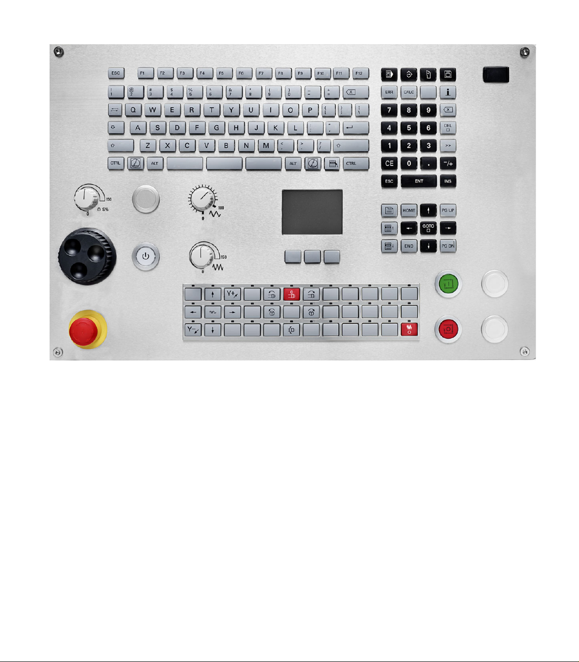
Operating panel of the CNC PILOT
Page 4

Page 5

CNC PILOT 620/640, Software and features
This manual describes functions that are available in the CNC PILOT
with NC software number 688945-03, 688946-01 and 688947-01.
The programming of smart.Turn and DIN PLUS are not included in this
manual. These functions are described in the User's Manual for
smart.Turn and DIN PLUS Programming (ID 685556-xx). Please
contact HEIDENHAIN if you require a copy of this manual.
The machine manufacturer adapts the features offered by the control
to the capabilities of the specific machine tool by setting machine
parameters. Therefore, some of the functions described in this manual
may not be among the features provided by the CNC PILOT on your
machine tool.
Some of the CNC PILOT functions that are not available on every
machine are:
Positioning of spindle (M19) and driven tool
Operations with the C or Y axis
Please contact your machine manufacturer for detailed information on
the features that are supported by your machine tool.
Many machine manufacturers and HEIDENHAIN offer programming
courses. We recommend these courses as an effective way of
improving your programming skill and sharing information and ideas
with other CNC PILOT users.
HEIDENHAIN also offers the DataPilot MP620 or DataPilot CP 620
software for personal computers, which is designed to simulate the
functions of the MANUALplus 620 and CNC PILOT 620/640. The
DataPilot is suitable for both shop-floor programming as well as offlocation program creation and testing. It is also ideal for training
purposes. The DataPilot can be run on PCs with WINDOWS
operating systems.
Intended place of operation
The CNC PILOT complies with the limits for a Class A devices in
accordance with the specifications in EN 55022, and is intended for
use primarily in industrially-zoned areas.
Legal information
This product uses open source software. Further information is
available on the control under
Programming and Editing operating mode
MOD function
LICENSE INFO soft key
HEIDENHAIN CNC PILOT 620/640 5
Page 6

New functions of software 688945-02
In the program simulation, the current contour description (of
workpiece blank and finished part) can be mirrored and saved. In
smart.Turn, these contours can be reinserted (see page 369)
On machines with counterspindle, the workpiece spindle can now
be selected in the TSF menu (see page 93)
On machines with a counterspindle, it’s datum can be shifted (see
Page 93)
The user documentation is now also available in the context-
sensitive help system TURNguide (see page 64)
You can make your own project folder in the project management,
so that you can centrally manage associated files (see page 114)
With a manual tool change system it is possible to insert tools that
are not in the turret during a program run (see page 484)
Engraving cycles are now available in the Teach-In mode of
operation (see Page 328)
During tool data backup, you can now select in a dialog window the
data to be saved or restored (see page 554)
The G30 function is now available for converting G functions, M
functions or spindle numbers, as well as for mirroring traverse paths
and tool dimensions (see the smart.Turn and ISO Programming
User’s Manual)
The "traverse to a fixed stop" function (G916) is now available for
transferring the workpiece to the second traversable spindle or for
pressing the tailstock against the workpiece (see the smart.Turn and
ISO Programming User’s Manual)
The G925 function makes it possible to define and monitor the
maximum contact force for an axis. This function can be applied to
use the opposing spindle as a mechatronic tailstock, for example
(see the smart.Turn and ISO Programming User’s Manual)
Controlled parting using servo-lag monitoring (G917) can now be
activated to prevent collisions caused by incomplete parting
processes (see the smart.Turn and ISO Programming User’s
Manual)
6
Page 7

The spindle synchronization option G720 synchronizes the shaft
speeds of two or more spindles so that they rotate synchronously
with a gear ratio or a defined offset (see the smart.Turn and ISO
Programming User’s Manual)
In combination with the synchronization (G720) of main spindle and
tool spindle, the new "Hobbing" cycle (G808) is available for milling
external teeth and profiles (see the smart.Turn and ISO
Programming User’s Manual)
With G924, a "fluctuating speed" can now be programmed to
prevent resonance (see the smart.Turn and ISO Programming
User’s Manual)
HEIDENHAIN CNC PILOT 620/640 7
Page 8

New functions of software 688945-03 and 688946-01
In the Organization mode of operation, you can grant or restrict
access to the control by using the EXTERNAL ACCESS soft key (see
also "Organization mode of operation" on page 512)
The pocket calculator can now be activated in each application and
also remains active after a change in operating modes. The Get
current value and Load current value soft keys enable you to
fetch numerical values from an active input field or to transfer them
to an active input field (see also "Integrated calculator" on page 56)
Tool touch probes can now be calibrated in the Machine Setup
menu (see also "Calibrating the tool touch probe" on page 95)
The workpiece datum can now also be set in the direction of the Z
axis using a touch probe (see also "Machine setup" on page 89)
In Teach-in mode, the oversizes RI and RK for the workpiece blank
were introduced for finishing in the recess-turning cycles (see also
"Recess turning, radial finishing—expanded" on page 232)
On machines with a B axis it is now also possible to drill, bore, and
mill in oblique planes. In addition to this, the B axis enables you to
use tools even more flexibly during turning (see smart.Turn and DIN
Programming User's Manual).
The control now provides numerous touch probe cycles for various
applications (see smart.Turn and DIN Programming User's Manual):
Calibrating a touch trigger probe
Measuring circles, circle segments, angle and position of the C
axis
Misalignment compensation
Single- point and double-point measurement
Finding a hole or stud
Zero point setting in the Z or C axis
Automatic tool measurement
8
Page 9

The new TURN PLUS function automatically generates NC
programs for turning and milling operations based on a fixed
machining sequence (see smart.Turn and DIN Programming User's
Manual).
The G940 function now provides a way to calculate the tool lengths
in the basic (definition) position of the B axis (see smart.Turn and
DIN Programming User's Manual).
For machining operations that require rechucking, you can define a
separation point on the contour description with G44 (see
smart.Turn and DIN Programming User's Manual).
The G927 function enables you to convert tool lengths to the
reference position of the tool (B axis = 0) (see smart.Turn and DIN
Programming User's Manual).
Recesses that were defined with G22 can now be machined with
the new Cycle 870 ICP Recessing (see smart.Turn and DIN
Programming User's Manual).
HEIDENHAIN CNC PILOT 620/640 9
Page 10

10
Page 11
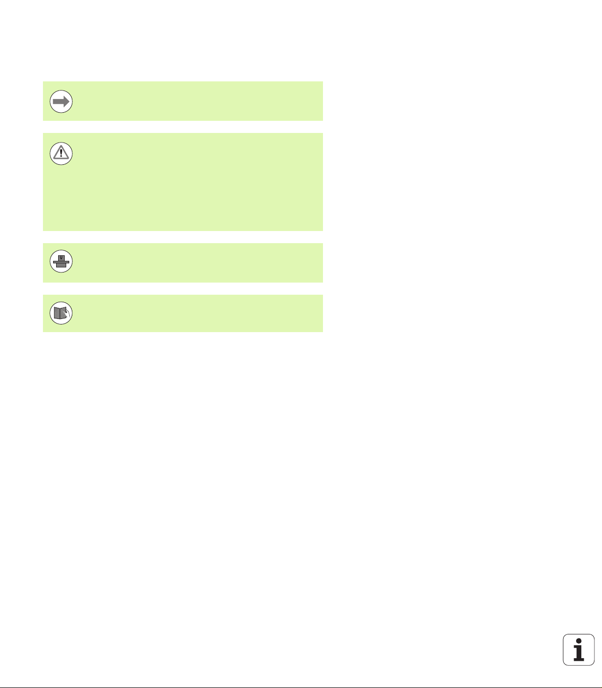
About this manual
The symbols used in this manual are described below.
This symbol indicates that important information about the
function described must be considered.
This symbol indicates that there is one or more of the
following risks when using the described function:
Danger to workpiece
Danger to fixtures
Danger to tool
Danger to machine
Danger to operator
This symbol indicates that the described function must be
adapted by the machine tool builder. The function
described may therefore vary depending on the machine.
This symbol indicates that you can find detailed
information about a function in another manual.
About this manual
Do you want any changes, or have you found any errors?
We are continuously striving to improve our documentation for you.
Please help us by sending your requests to the following e-mail
address: tnc-userdoc@heidenhain.de.
HEIDENHAIN CNC PILOT 620/640 11
Page 12

About this manual
12
Page 13

Contents
Introduction and fundamentals
1
Basics of operation
2
Machine mode of operation
3
Teach-in mode
4
ICP programming
5
Graphic simulation
6
Tool and technology database
7
Organization mode of operation
8
Tables and overviews
9
Overview of cycles
10
HEIDENHAIN CNC PILOT 620/640 13
Page 14

Page 15

1 Introduction and fundamentals ..... 33
1.1 The CNC PILOT ..... 34
1.2 Configuration ..... 35
Slide position ..... 35
Tool carrier systems ..... 35
The C axis ..... 35
The Y axis ..... 36
Full-surface machining ..... 37
1.3 Features ..... 38
Configuration ..... 38
Operating modes ..... 38
1.4 Data backup ..... 40
1.5 Explanation of terms ..... 41
1.6 CNC PILOT design ..... 42
1.7 Fundamentals ..... 43
Position encoders and reference marks ..... 43
Axis designations ..... 43
Coordinate system ..... 44
Absolute coordinates ..... 44
Incremental coordinates ..... 45
Polar coordinates ..... 45
Machine zero point ..... 45
Workpiece zero point ..... 46
Units of measure ..... 46
1.8 Tool dimensions ..... 47
Tool length ..... 47
Tool compensation ..... 47
Tool-tip radius compensation (TRC) ..... 48
Milling cutter radius compensation (MCRC) ..... 48
HEIDENHAIN CNC PILOT 620/640 15
Page 16

2 Basics of operation ..... 49
2.1 General information on operation ..... 50
Operation ..... 50
Setup ..... 50
Programming – Teach-in mode ..... 50
Programming – smart.Turn ..... 50
2.2 The CNC PILOT screen ..... 51
2.3 Operation and data input ..... 52
Operating modes ..... 52
Menu selection ..... 53
Soft keys ..... 53
Data input ..... 54
smart.Turn dialogs ..... 54
List operations ..... 54
Alphanumeric keyboard ..... 55
2.4 Integrated calculator ..... 56
Calculator functions ..... 56
Adjusting the position of the calculator ..... 58
2.5 Types of programs ..... 59
2.6 The error messages ..... 60
Display of errors ..... 60
Opening the error window ..... 60
Closing the error window ..... 60
Detailed error messages ..... 61
"Details" soft key ..... 61
Clearing errors ..... 62
Error log file ..... 62
Keystroke log file ..... 63
Saving service files ..... 63
2.7 TURNguide context-sensitive help system ..... 64
Application ..... 64
Working with the TURNguide ..... 65
Downloading current help files ..... 69
16
Page 17

3 Machine mode of operation ..... 71
3.1 Machine mode of operation ..... 72
3.2 Switch-on / Switch-off ..... 73
Switch-on ..... 73
Monitoring EnDat encoders ..... 73
Traversing the reference marks ..... 74
Switch-off ..... 75
3.3 Machine data ..... 76
Input of machine data ..... 76
Machine data display ..... 78
Cycle statuses ..... 81
Axis feed rate ..... 82
Spindle ..... 82
3.4 Setting up a tool list ..... 83
Machine with turret ..... 83
Machine with multifix ..... 83
Tools in different quadrants ..... 84
Filling the turret list from the database ..... 85
Filling the turret list ..... 86
Tool call ..... 87
Driven tools ..... 87
Tool life monitoring ..... 88
3.5 Machine setup ..... 89
Defining the workpiece zero point ..... 89
Homing the axes ..... 90
Setting the protection zone ..... 91
Defining the tool change position ..... 92
Setting C-axis values ..... 93
Setting up machine dimensions ..... 94
Calibrating the tool touch probe ..... 95
3.6 Tool measurement ..... 96
Touch off ..... 97
Touch probe (tool touch probe) ..... 98
Optical gauge ..... 99
Tool compensation ..... 100
3.7 "Manual Operation" operating mode ..... 101
Tool change ..... 101
Spindle ..... 101
Handwheel operation ..... 101
Manual direction keys ..... 102
Teach-in cycles in Manual mode ..... 102
3.8 Teach-in mode ..... 103
Teach-in mode ..... 103
Programming Teach-in cycles ..... 103
HEIDENHAIN CNC PILOT 620/640 17
Page 18

3.9 Program Run mode ..... 104
Loading a program ..... 104
Comparing a tool list ..... 105
Before executing a program ..... 105
Finding a start block ..... 106
Program execution ..... 107
Entering compensation values during program run ..... 108
Program execution in "dry run" mode ..... 110
3.10 Graphic simulation ..... 111
3.11 Program management ..... 112
Program selection ..... 112
File manager ..... 113
Project management ..... 114
3.12 Conversion into DIN format ..... 115
Making a conversion ..... 115
3.13 Units of measure ..... 116
18
Page 19

4 Teach-in mode ..... 117
4.1 Working with cycles ..... 118
Cycle starting point ..... 118
Help graphics ..... 119
DIN macros ..... 119
Graphical test run (simulation) ..... 119
Contour follow-up in Teach-in mode ..... 120
Cycle keys ..... 120
Switching functions (M functions) ..... 120
Comments ..... 121
Cycle menu ..... 122
Addresses used in many cycles ..... 124
4.2 Workpiece blank cycles ..... 125
Bar/tube blank ..... 126
ICP workpiece blank contour ..... 127
4.3 Single cut cycles ..... 128
Rapid traverse positioning ..... 129
Approaching the tool change position ..... 130
Linear machining, longitudinal ..... 131
Linear machining, transverse ..... 132
Linear machining at angle ..... 133
Circular machining ..... 135
Chamfer ..... 137
Rounding arc ..... 139
M functions ..... 141
HEIDENHAIN CNC PILOT 620/640 19
Page 20

4.4 Turning cycles ..... 142
Tool position ..... 143
Roughing, longitudinal ..... 145
Cut, transverse ..... 147
Roughing, longitudinal—expanded ..... 149
Roughing, transverse—expanded ..... 151
Finishing cut, longitudinal ..... 153
Finishing cut, transverse ..... 154
Finishing cut, longitudinal—expanded ..... 155
Finishing cut, transverse—expanded ..... 157
Cut, longitudinal plunge ..... 159
Cut, transverse plunge ..... 161
Cut, longitudinal plunging—expanded ..... 163
Cut, transverse plunging—expanded ..... 165
Cut, longitudinal finishing plunge ..... 167
Cut, transverse finishing plunge ..... 168
Cut, longitudinal finishing plunge—expanded ..... 170
Cut, transverse finishing plunge—expanded ..... 172
Cut, ICP contour-parallel, longitudinal ..... 174
Cut, ICP contour-parallel, transverse ..... 176
Cut, ICP contour-parallel, longitudinal finishing ..... 178
Cut, ICP contour-parallel, transverse finishing ..... 180
ICP cutting, longitudinal ..... 182
ICP cutting, transverse ..... 184
ICP longitudinal finishing cut ..... 186
ICP transverse finishing cut ..... 188
Examples of turning cycles ..... 190
20
Page 21

4.5 Recessing cycles ..... 194
Cutting and infeed directions for recessing cycles ..... 194
Undercut position ..... 195
Contour forms ..... 195
Recessing, radial ..... 196
Recessing, axial ..... 198
Recessing, radial—expanded ..... 200
Recessing, axial—expanded ..... 202
Recessing radial, finishing ..... 204
Recessing axial, finishing ..... 206
Recessing radial, finishing—expanded ..... 208
Recessing axial, finishing—expanded ..... 210
ICP recessing cycles, radial ..... 212
ICP recessing cycles, axial ..... 214
ICP recessing, radial finishing ..... 216
ICP recessing, axial finishing ..... 218
Recess turning ..... 220
Recess turning, radial ..... 221
Recess turning, axial ..... 222
Recess turning, radial—expanded ..... 224
Recessing turning, axial—expanded ..... 226
Recess turning, radial finishing ..... 228
Recess turning, axial finishing ..... 230
Recess turning, radial finishing—expanded ..... 232
Recess turning, axial finishing—expanded ..... 234
ICP recess turning, radial ..... 236
ICP recess turning, axial ..... 238
ICP recess turning, radial finishing ..... 240
ICP recess turning, axial finishing ..... 242
Undercutting type H ..... 244
Undercutting type K ..... 246
Undercutting type U ..... 247
Parting ..... 249
Examples of recessing cycles ..... 251
HEIDENHAIN CNC PILOT 620/640 21
Page 22

4.6 Thread and undercut cycles ..... 253
Thread position, undercut position ..... 253
Handwheel superimposition ..... 254
Feed angle, thread depth, proportioning of cuts ..... 254
Thread run-in / thread run-out ..... 255
Last cut ..... 256
Thread cycle (longitudinal) ..... 257
Thread cycle (longitudinal)—expanded ..... 259
Tapered thread ..... 262
API thread ..... 264
Recut (longitudinal) thread ..... 266
Recut (longitudinal) thread—expanded ..... 268
Recut tapered thread ..... 270
Recut API thread ..... 272
Undercut DIN 76 ..... 274
Undercut DIN 509 E ..... 276
Undercut DIN 509 F ..... 278
Examples of thread and undercut cycles ..... 280
4.7 Drilling cycles ..... 282
Drilling, axial ..... 283
Radial drilling ..... 285
Deep-hole drilling, axial ..... 287
Deep-hole drilling, radial ..... 290
Tapping, axial ..... 292
Tapping, radial ..... 294
Thread milling, axial ..... 296
Examples of drilling cycles ..... 298
4.8 Milling cycles ..... 300
Rapid positioning milling ..... 301
Slot, axial ..... 302
Figure, axial ..... 304
ICP contour, axial ..... 308
Face milling ..... 311
Slot, radial ..... 314
Figure, radial ..... 316
ICP contour, radial ..... 320
Helical-slot milling, radial ..... 323
Milling direction for contour milling ..... 325
Milling direction for pocket milling ..... 326
Example of milling cycle ..... 327
Engraving, axial ..... 328
Engraving, radial ..... 330
Engraving, axial/radial ..... 332
22
Page 23

4.9 Drilling and milling patterns ..... 333
Linear drilling pattern, axial ..... 334
Milling pattern linear, axial ..... 336
Drilling pattern circular, axial ..... 338
Milling pattern circular, axial ..... 340
Drilling pattern linear, radial ..... 342
Linear milling pattern, radial ..... 344
Drilling pattern circular, radial ..... 346
Circular milling pattern, radial ..... 348
Examples of pattern machining ..... 350
4.10 DIN cycles ..... 353
DIN cycle ..... 353
HEIDENHAIN CNC PILOT 620/640 23
Page 24

5 Graphic simulation ..... 355
5.1 Simulation mode of operation ..... 356
Using the graphic simulation ..... 357
The miscellaneous functions ..... 358
5.2 Simulation window ..... 359
Setting up the views ..... 359
Single-window view ..... 360
Multiple window view ..... 360
5.3 Views ..... 361
Traverse path display ..... 361
Tool depiction ..... 362
Material-removal graphic ..... 362
3-D view ..... 363
5.4 The zoom function ..... 364
Adjusting the visible section ..... 364
5.5 Simulation with mid-program startup ..... 366
Startup block with smart.Turn programs ..... 366
Mid-program startup in cycle programs ..... 367
5.6 Time calculation ..... 368
Showing the machining times ..... 368
5.7 Saving the contour ..... 369
Saving the generated contour in the simulation ..... 369
24
Page 25

6 ICP programming ..... 371
6.1 ICP contours ..... 372
Loading contours ..... 372
Form elements ..... 373
Machining attributes ..... 373
Calculation of contour geometry ..... 374
6.2 ICP editor in cycle mode ..... 375
Editing contours for cycles ..... 375
File organization with the ICP editor ..... 376
6.3 ICP editor in smart.Turn ..... 377
Editing a contour in smart.Turn ..... 378
6.4 Creating an ICP contour ..... 380
Entering an ICP contour ..... 380
Absolute or incremental dimensioning ..... 381
Transitions between contour elements ..... 381
Polar coordinates ..... 382
Angular input ..... 382
Contour graphics ..... 383
Selection of solutions ..... 384
Colors in contour graphics ..... 384
Selection functions ..... 385
Contour direction (cycle programming) ..... 386
6.5 Editing ICP contours ..... 387
Superimposing form elements ..... 387
Adding contour elements ..... 387
Editing or deleting the last contour element ..... 388
Deleting a contour element ..... 388
Editing contour elements ..... 389
6.6 The zoom function in the ICP editor ..... 392
Changing the view ..... 392
6.7 Defining the workpiece blank ..... 393
"Bar" blank ..... 393
"Tube" blank ..... 393
6.8 Contour elements of a turning contour ..... 394
Basic elements of a turning contour ..... 394
Contour form elements ..... 398
6.9 Contour elements on face ..... 405
Starting point of face contour ..... 405
Vertical lines on face ..... 406
Horizontal lines on face ..... 407
Line at angle on face ..... 408
Circular arc on face ..... 409
Chamfer/rounding arc on the face ..... 410
HEIDENHAIN CNC PILOT 620/640 25
Page 26

6.10 Contour elements on lateral surface ..... 411
Starting point of lateral surface contour ..... 411
Vertical lines on lateral surface ..... 413
Horizontal lines on lateral surface ..... 413
Line at angle on lateral surface ..... 414
Circular arc on lateral surface ..... 415
Chamfers/rounding arcs on a lateral surface ..... 416
6.11 C and Y axis machining in smart.Turn ..... 417
Reference data, nested contours ..... 418
Representation of the ICP elements in the smart.Turn program ..... 419
6.12 Face contours in smart.Turn ..... 420
Reference data for complex face contours ..... 420
TURN PLUS attributes ..... 421
Circle on face ..... 421
Rectangle on face ..... 422
Polygon on face ..... 423
Linear slot on face ..... 424
Circular slot on face ..... 424
Hole on face ..... 425
Linear pattern on face ..... 426
Circular pattern on face ..... 427
6.13 Lateral surface contours in smart.Turn ..... 428
Reference data of lateral surface ..... 428
TURN PLUS attributes ..... 429
Circle on lateral surface ..... 430
Rectangle on lateral surface ..... 431
Polygon on lateral surface ..... 432
Linear slot on lateral surface ..... 433
Circular slot on lateral surface ..... 434
Hole on lateral surface ..... 435
Linear pattern on lateral surface ..... 436
Circular pattern on lateral surface ..... 437
26
Page 27

6.14 Contours in the XY plane ..... 439
Reference data in XY plane ..... 439
Starting point of contour in XY plane ..... 440
Vertical lines in XY plane ..... 440
Horizontal lines in XY plane ..... 441
Line at angle in XY plane ..... 442
Circular arc in XY plane ..... 443
Chamfer/rounding arc in XY plane ..... 444
Circle in XY plane ..... 445
Rectangle in XY plane ..... 446
Polygon in XY plane ..... 447
Linear slot in XY plane ..... 448
Circular slot in XY plane ..... 449
Hole in XY plane ..... 450
Linear pattern in XY plane ..... 451
Circular pattern in XY plane ..... 452
Single surface in XY plane ..... 453
Centric polygon in XY plane ..... 454
6.15 Contours in the YZ plane ..... 455
Reference data in YZ plane ..... 455
TURN PLUS attributes ..... 456
Starting point of contour in YZ plane ..... 457
Vertical lines in YZ plane ..... 457
Horizontal lines in YZ plane ..... 458
Line at angle in YZ plane ..... 459
Circular arc in YZ plane ..... 460
Chamfer/rounding arc in YZ plane ..... 461
Circle in YZ plane ..... 462
Rectangle in YZ plane ..... 463
Polygon in YZ plane ..... 464
Linear slot in YZ plane ..... 464
Circular slot in YZ plane ..... 465
Hole in YZ plane ..... 466
Linear pattern in YZ plane ..... 467
Circular pattern in YZ plane ..... 468
Single surface in YZ plane ..... 469
Centric polygons in YZ plane ..... 470
6.16 Loading existing contours ..... 471
Integrating cycle contours in smart.Turn ..... 471
DXF contours (option) ..... 472
HEIDENHAIN CNC PILOT 620/640 27
Page 28

7 Tool and technology database ..... 475
7.1 Tool database ..... 476
Tool types ..... 476
Multipoint tools ..... 477
Tool life management ..... 477
7.2 Tool editor ..... 478
Tool list ..... 478
Editing the tool data ..... 479
Tool texts ..... 480
Editing multipoint tools ..... 481
Editing tool-life data ..... 483
Manual change systems ..... 484
7.3 Tool data ..... 489
General tool parameters ..... 489
Standard turning tools ..... 492
Recessing tools ..... 493
Thread-cutting tools ..... 494
Twist drills and indexable-insert drills ..... 495
NC center drill ..... 496
Centering tool ..... 497
Counterbore ..... 498
Countersink ..... 499
Tap ..... 500
Standard milling tools ..... 501
Thread milling tools ..... 502
Angle cutters ..... 503
Milling pins ..... 504
Touch probes ..... 505
7.4 Technology database ..... 506
Technology editor ..... 507
Editing a workpiece material or cutting material list ..... 508
Displaying/editing cutting data ..... 509
28
Page 29

8 Organization mode of operation ..... 511
8.1 Organization mode of operation ..... 512
8.2 Parameters ..... 513
Parameter editor ..... 513
List of user parameters ..... 515
Machining parameters (processing) ..... 519
General settings ..... 519
Thread cutting ..... 534
8.3 Transfer ..... 539
Data backup ..... 539
Data exchange with TNCremo ..... 539
External access ..... 539
Connections ..... 540
Ethernet interface CNC PILOT 620 ..... 541
Ethernet interface CNC PILOT 640 ..... 542
USB connection ..... 549
Data transfer options ..... 550
Transferring programs (files) ..... 551
Transferring parameters ..... 553
Transferring tool data ..... 554
Service files ..... 555
Creating a data backup file ..... 556
Importing NC programs from predecessor controls ..... 557
8.4 Service pack ..... 561
Installing a service pack ..... 561
Uninstalling a service pack (with software 548328-xx) ..... 562
HEIDENHAIN CNC PILOT 620/640 29
Page 30

9 Tables and overviews ..... 565
9.1 Thread pitch ..... 566
Thread parameters ..... 566
Thread pitch ..... 567
9.2 Undercut parameters ..... 573
DIN 76—undercut parameters ..... 573
DIN 509 E – undercut parameters ..... 575
DIN 509 F – undercut parameters ..... 575
9.3 Technical information ..... 576
30
Page 31

10 Overview of cycles ..... 585
10.1 Workpiece blank cycles, single cut cycles ..... 586
10.2 Turning cycles ..... 587
10.3 Recessing and recess-turning cycles ..... 588
10.4 Thread cycles ..... 589
10.5 Drilling cycles ..... 590
10.6 Milling cycles ..... 591
HEIDENHAIN CNC PILOT 620/640 31
Page 32

32
Page 33

Introduction and fundamentals
HEIDENHAIN CNC PILOT 620/640 33
Page 34

1.1 The CNC PILOT
The CNC PILOT was conceived for CNC lathes. It is suitable for
horizontal and vertical lathes. The CNC PILOT supports lathes with
tool turrets. The tool carrier of horizontal lathes can be located in front
of or behind the workpiece.
The CNC PILOT supports lathes with spindle, one slide (X and Z axis),
C axis or positionable spindle, driven tool and machines with a Y axis.
Regardless of whether you are turning simple parts or complex
workpieces, the CNC PILOT provides you with the benefits of
graphical contour input and convenient programming with smart.Turn.
1.1 The CNC PILOT
Programming with variables, controlling special machine components,
or using externally created programs, etc. is no problem: Switch to
DINplus. This programming mode helps you solve all your special
tasks.
The MANUALplus also offers the powerful Teach-in mode. It enables
you to perform simple machining, rework or repair operations without
writing NC programs.
The CNC PILOT supports operations with the C axis in cycle,
smart.Turn and DIN programming. In the Y axis, the CNC PILOT
supports operations with smart.Turn and DIN programming.
34 Introduction and fundamentals
Page 35

1.2 Configuration
In the standard version, the control is equipped with the axes X and Z
and a main spindle. Optionally, a C axis, a Y axis, and a driven tool can
be configured.
Slide position
The machine tool builder configures the CNC PILOT. These are the
available possibilities:
Z axis horizontal with tool slide behind the workpiece
Z axis horizontal with tool slide in front of the workpiece
Z axis vertical with tool slide to the right of the workpiece
The menu symbols, help graphics and graphic representations during
ICP and simulation consider the slide position.
The representations in this User’s Manual assume a lathe with tool
carrier behind the workpiece.
Tool carrier systems
The CNC PILOT supports turrets with a number n of tool mounts as
tool carriers.
The C axis
1.2 Configuration
With a C axis you can drill and mill a workpiece on its face and lateral
surfaces.
When the C axis is used, one axis interpolates linearly or circularly with
the spindle in the given working plane, while the third axis interpolates
linearly.
The CNC PILOT supports part program creation with the C axis in:
Teach-in mode
smart.Turn programming
DINplus programming
HEIDENHAIN CNC PILOT 620/640 35
Page 36

The Y axis
With a Y axis you can drill and mill a workpiece on its face and lateral
surfaces.
During use of the Y axis, two axes interpolate linearly or circularly in
the given working plane, while the third axis interpolates linearly. This
enables you to machine slots or pockets, for example, with plane
floors and perpendicular edges. By defining the spindle angle, you can
determine the position of the milling contour on the workpiece.
The CNC PILOT supports program creation with the Y axis in:
Teach-in mode
1.2 Configuration
smart.Turn programs
in DINplus programs
36 Introduction and fundamentals
Page 37

Full-surface machining
Functions like angle-synchronous part transfer with rotating spindle,
traversing to a stop, controlled parting, and coordinate transformation
ensures efficient machining as well as simple programming of fullsurface machining.
The CNC PILOT supports full-surface machining for all common
machine designs.
Examples: Lathes with
Rotating gripper
Movable opposing spindle
Several spindles, slides and tool carriers
1.2 Configuration
HEIDENHAIN CNC PILOT 620/640 37
Page 38

1.3 Features
Configuration
Basic version: X and Z axis, spindle
Positionable spindle and driven tool
C axis and driven tool
1.3 Features
Y axis and driven tool
B axis for machining a tilted plane
Digital current and speed control
Operating modes
Manual operation
Manual slide movement through axis-direction keys or electronic
handwheels.
Graphic support for entering and running Teach-in cycles without
saving the machining steps in alternation with manual machine
operation.
Thread reworking (thread repair in a second workpiece setup).
Teach-in mode
Sequential linking of Teach-in cycles, where each cycle is run
immediately after input, or is graphically simulated and subsequently
saved.
Program run
All are possible in single-block and full-sequence modes
DINplus programs
smart.Turn programs
Teach-in programs
Setup functions
Workpiece datum setting
Definition of tool-change position
Definition of protection zone
Tool measurement through touch-off, touch probe or optical gauge
Programming
Teach-in programming
Interactive Contour Programming (ICP)
smart.Turn programming
Automatic program creation with TURN PLUS
DINplus programming
38 Introduction and fundamentals
Page 39

Graphic simulation
Graphic depiction of the sequence of smart.Turn or DINplus
programs and graphic depiction of a Teach-in cycle or Teach-in
program
Simulation of the tool paths as wire-frame or cutting-path graphics,
special identification of the rapid-traverse paths
Machining simulation (2-D material-removal graphic)
Side or face view, or 2-D view of cylindrical surface
Display of programmed contours
Shifting and magnifying functions
Tool system
Database for 250 tools, optionally 999 tools
Description can be entered for every tool
Optional support of multipoint tools (tools with multiple reference
points or multiple cutting edges)
Turret or multifix system
Technology database
The cutting data are entered in the cycle or in the UNIT as default
values.
9 workpiece-material/tool-material combinations (144 entries)
Optionally 62 workpiece-material/tool-material combinations (992
entries)
Interpolation
Linear: In 2 principal axes (max. ± 100 m)
Circular: in 2 axes (radius max. 999 m)
C axis: Interpolation in the linear axes X and Z with the C axis
Y axis: Linear or circular interpolation of two axes in the given plane.
The respective third axis can simultaneously perform linear
interpolation.
G17: XY plane
G18: XZ plane
G19: YZ plane
B axis: Drilling, boring and milling operations in oblique planes
1.3 Features
HEIDENHAIN CNC PILOT 620/640 39
Page 40

1.4 Data backup
HEIDENHAIN recommends saving new programs and files created on
a PC at regular intervals.
HEIDENHAIN provides a backup function for this purpose in the data
transfer software TNCremoNT. Your machine tool builder can provide
you with a copy.
You additionally need a data medium on which all machine-specific
data, such as the PLC program, machine parameters, etc., are stored.
1.4 Data backup
Please contact your machine tool builder.
40 Introduction and fundamentals
Page 41

1.5 Explanation of terms
Cursor: In lists, or during data input, a list item, an input field or a
character is highlighted. This "highlight" is called a cursor. Entries
and operations, like copying, deleting, inserting a new item, etc.,
refer to the current cursor position.
Arrow keys: The cursor is moved with the horizontal and vertical
arrow keys and with the PG UP / PG DN keys.
Page keys: The PG UP / PG DN keys are also called “Page keys.”
Navigating: Within a list or an input box, you can move the cursor
to any position you would like to check, change, delete or add to. In
other words, you "navigate" through the list.
Active/ inactive windows, functions, menu items: Of all
windows that are displayed on the screen, only one is active. That
means, any data you type on the keyboard or keypad are entered in
the active window only. In the active window the title bar is shown
in color. In the inactive windows, the title bar appears dimmed.
Inactive function keys or menu keys also appear dimmed.
Menu, menu key: The CNC PILOT arranges the available functions
and function groups in a 9-field box. This box is called a menu. Each
symbol in the menu is a menu key.
Editing: Editing is changing, deleting and adding to parameters,
commands, etc. within programs, tool data or parameters.
Default value: If the parameters of cycles or DIN commands are
preassigned values, these values are referred to as default values.
These values are used if you do not enter the parameters.
Byte: The capacity of storage media is measured in bytes. Since the
CNC PILOT features an internal memory, the individual program
lengths are expressed in bytes.
Extension: File names consist of the actual name and the
extension. The name part and the extension part are separated by a
dot ("."). The extension indicates the type of file. Examples:
*.NC "DIN programs"
*.NCS "DIN subprograms (DIN macros)"
Soft key: Soft keys are the unmarked keys along the side of the
screen. The meaning of each key is shown on the screen.
Form: The individual pages of a dialog are shown as easy-to-fill
forms.
UNITS: A UNIT is a group of function united into a dialog in
smart.Turn.
1.5 Explanation of terms
HEIDENHAIN CNC PILOT 620/640 41
Page 42

1.6 CNC PILOT design
The dialog between machinist and control takes place via:
Screen
Soft keys
Data input keypad
Machine operating panel
The entered data can be displayed and checked on the screen. With
the soft key directly below the screen, you can select functions,
capture position values, confirm entries, and a lot more.
With the ERR key you can call error and PLC information.
The data input keyboard (operating panel) serves for the input of
1.6 CNC PILOT design
machine data, positioning data, etc. The CNC PILOT does not need an
alphanumeric keyboard. Tool descriptions, program descriptions or
comments in a DIN program are entered with an on-screen
alphanumeric keyboard. The machine operating panel contains all
necessary controls for manual operation of the lathe.
The actual control is not accessible to the machinist. You should know,
however, that your control has an integrated memory on which all
cycle programs, ICP contours and DIN programs that you enter are
stored. This allows you to save a very large number of programs.
For data exchange and data backup, you can use the Ethernet
interface and the USB interface.
42 Introduction and fundamentals
Page 43

1.7 Fundamentals
Zref
Xref
M
M
Z
Z+
Y+
X
X+
Position encoders and reference marks
The machine axes are equipped with position encoders that register
the positions of the slide or tool. When a machine axis moves, the
corresponding position encoder generates an electrical signal. The
control evaluates this signal and calculates the precise actual position
of the machine axis.
If there is a power interruption, the calculated position will no longer
correspond to the actual position of the machine slide. To recover this
association, incremental position encoders are provided with
reference marks. The scales of the position encoders contain one or
more reference marks that transmit a signal to the control when they
are crossed over. This enables the CNC PILOT to re-establish the
assignment of the displayed position to the current machine position.
For linear encoders with distance-coded reference marks, you only
need to move each axis a maximum of 20 mm (0.8 in.) for these, and
a maximum of 20° for angle encoders.
If incremental encoders are without reference marks, fixed reference
positions have to be traversed after switch-on. The control knows the
exact distance between these reference points and the machine
datum (see figure).
With absolute encoders, an absolute position value is transmitted to
the control immediately upon switch-on. In this way the assignment
of the actual position to the machine slide position is re-established
directly after switch-on.
X
MP
X (Z,Y)
1.7 Fundamentals
Axis designations
The cross slide is referred to as the X axis and the saddle as the Z
axis.
All X-axis values that are displayed or entered are regarded as
diameters.
Lathes with Y axis: The Y axis is perpendicular to the X axis and Z axis
(Cartesian system).
When programming paths of traverse, remember to:
Program a positive value to depart the workpiece.
Program a negative value to approach the workpiece.
HEIDENHAIN CNC PILOT 620/640 43
Page 44
Coordinate system
The meanings of the coordinates X, Y, Z, and C are specified in
DIN 66 217.
The coordinates entered for the principal axes X and Z are referenced
to the workpiece zero point. The angles entered for the rotary axis
(C axis) are referenced to the datum of the C axis.
The axis designations X and Z describe positions in a two-dimensional
coordinate system. As you can see from the figure to the center right,
the position of the tool tip is clearly defined by its X and Z coordinates.
The CNC PILOT can connect points by linear and circular paths of
1.7 Fundamentals
traverse (interpolations). Workpiece machining is programmed by
entering the coordinates for a succession of points and connecting the
points by linear or circular paths of traverse.
Like the paths of traverse, you can also describe the complete contour
of a workpiece by defining single points through their coordinates and
connecting them by linear or circular paths of traverse.
Positions can be programmed to an accuracy of 1 µm (0.001 mm). This
is also the accuracy with which they are displayed.
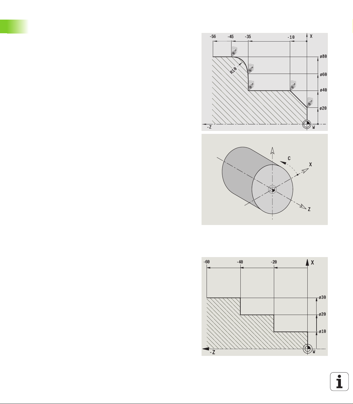
Absolute coordinates
If the coordinates of a position are referenced to the workpiece datum,
they are referred to as absolute coordinates. Each position on a
workpiece is clearly defined by its absolute coordinates (see figure).
44 Introduction and fundamentals
Page 45

Incremental coordinates
Incremental coordinates are always given with respect to the last
programmed position. They specify the distance from the last active
position and the subsequent position. Each position on a workpiece is
clearly defined by its incremental coordinates (see figure).
Polar coordinates
Positions located on the face or lateral surface can either be entered
in Cartesian coordinates or polar coordinates.
When programming with polar coordinates, a position on the
workpiece is clearly defined by the entries for diameter and angle (see
figure).
1.7 Fundamentals
Machine zero point
The point of intersection of the X and Z axes is called the machine
zero point. On a lathe, the machine zero point is usually the point of
intersection of the spindle axis and the spindle surface. It is designated
with the letter "M" (see figure).
HEIDENHAIN CNC PILOT 620/640 45
Page 46

Workpiece zero point
To machine a workpiece, it is easier to enter all input data with respect
to a zero point located on the workpiece. By programming the zero
point used in the workpiece drawing, you can take the dimensions
directly from the drawing, without further calculation. This point is the
workpiece zero point. It is designated with the letter "W" (see figure).
1.7 Fundamentals
Units of measure
You can program the CNC PILOT either in the metric or inch system.
The units of measurement listed in the table below apply to all inputs
and displays.
Dimensions Metric Inches
Coordinates mm inch
Lengths mm inch
Angle Degrees Degrees
Spindle speed rpm rpm
Cutting speed m/min ft/min
Feed per revolution mm/rev inch/rev
Feed per minute mm/min inch/min
Acceleration m/s
46 Introduction and fundamentals
2
ft/s
2
Page 47

1.8 Tool dimensions
The CNC PILOT requires information on the specific tools for a variety
of tasks, such as calculating the cutting radius compensation or the
proportioning of cuts.
Tool length
All programmed and displayed position values are given with respect
to the distance between the tool tip and workpiece zero point. Since
the control only knows the absolute position of the tool carrier (slide),
The CNC PILOT needs the dimensions XL and ZL (see figure) to
calculate and display the position of the tool tip.
Tool compensation
The tool tip is subjected to wear during machining processes. To
compensate for this wear, the CNC PILOT uses compensation values.
The compensation values are managed independent of the values for
length. The system automatically adds the compensation values to the
values for length.
1.8 Tool dimensions
HEIDENHAIN CNC PILOT 620/640 47
Page 48

Tool-tip radius compensation (TRC)
The tip of a lathe tool has a certain radius. When machining tapers,
chamfers and radii, this results in inaccuracies which the CNC PILOT
compensates with its cutting radius compensation function.
Programmed paths of traverse are referenced to the theoretical tool
tip S. With non-paraxial contours, this will lead to inaccuracies during
machining.
The TRC function compensates for this error by calculating a new path
of traverse, the equidistant line (see figure).
The CNC PILOT calculates the TRC for cycle programming. The
smart.Turn and DIN programming feature also takes the TRC for
clearance cycles into account. During DIN programming with single
1.8 Tool dimensions
paths, you can also enable/disable TRC.
Milling cutter radius compensation (MCRC)
In milling operations, the outside diameter of the milling cutter
determines the contour. When the MCRC function is not active, the
system defines the center of the cutter as reference point. The TRC
function compensates for this error by calculating a new path of
traverse, the equidistant line.
48 Introduction and fundamentals
Page 49

Basics of operation
HEIDENHAIN CNC PILOT 620/640 49
Page 50

2.1 General information on
operation
Operation
Select the desired operating mode with the corresponding operating
mode key.
Within the operating mode, you can change the mode through the
soft keys.
With the numeric keypad you can select the function within the
menus.
Dialogs can consist of multiple pages.
Besides with the soft keys, dialogs can be concluded positively with
"INS" or negatively with "ESC."
Changes made in lists are effective immediately. They are also
saved if the list is closed with "ESC" or "Cancel."
Setup
You will find all setup functions in the machine mode in "Manual
mode."
All preparatory work can be performed through the "setup" menu
item and "Set S,F,T."
2.1 General information on operation
Programming – Teach-in mode
Select Teach-in in the "machine" mode and use the Program list
soft key to open a new cycle program.
Activate the cycle menu through the Add cycle soft key. Here you
select the operation and enter the details.
Then press the Input finished soft key. Now you can start the
simulation and check the machining process.
Start the operation in the machine with "Cycle on."
Save that cycle after the operation is completed.
Repeat the last steps for each new operation.
Programming – smart.Turn
Convenient programming with UNITS in a structured NC program.
Combinable with DIN functions.
Contour definition is graphically possible.
Contour follow-up when used with a workpiece blank.
Conversion of cycle programs to smart.Turn programs with the
same functions.
50 Basics of operation
Page 51

2.2 The CNC PILOT screen
The CNC PILOT shows the data to be displayed in windows. Some
windows only appear when they are needed, for example, for typing
in entries.
In addition, the control shows the type of operation, the soft-key
display and the PLC soft key display on the screen. Each function
that appears in a field of the soft-key row is activated by pressing the
soft key directly below it.
Operating mode line
The operating mode tabs (at the top of the screen) shows the four
operating modes as well as the submodes.
Machine display
The machine display field (beneath the operating mode tabs) is
configurable. It shows all important information on axis positions, feed
rates, rotational speeds, and tool.
Other windows used:
List and program window
Display of program lists, tool lists, parameter lists, etc. To select
specific elements from the list, simply move the highlight to the
desired element with the arrow keys.
Menu window
Display of menu symbols. This window only appears on the screen
in the Teach-in and Manual modes.
Input window/Dialog window
For entering the parameters of a cycle, ICP element, DIN command,
etc. Look over the existing data, then delete or edit them in the
dialog window.
Graphic support window
Input data (such as cycle parameters, tool data, etc.) are explained
with graphics. The switchover key (the key with three rotating
arrows at the left edge of the screen) allows you to switch between
the help graphics for internal and external machining (only for cycle
programming).
Simulation window
The simulation window shows a graphic representation of the
contour elements and a simulation of the tool movements. This
enables you to check cycles, entire cycle programs, and
DIN programs.
ICP contour graphics
Display of the contour during ICP programming.
DIN editing window
Display of the DIN program during DIN programming.
Error window
Display of occurred errors and warnings.
2.2 The CNC PILOT screen
HEIDENHAIN CNC PILOT 620/640 51
Page 52

2.3 Operation and data input
Operating modes
The active mode of operation is highlighted in the operating-mode tab.
The CNC PILOT differentiates between the following operating
modes:
Machine—with the submodes:
Manual (display: "Machine")
Teach-in (Teach-in mode)
Program Run
Programming—with the submodes:
smart.Turn
Simulation
ICP
TURN PLUS: Automatic working plan generation (AWG)
2.3 Operation and data input
Tool management—with the submodes:
Tool editor
Technology editor
Organization—with the submodes:
User parameters
Transfer
User login
You can use the operating mode keys to switch between the modes.
The selected submode and the current menu position remain during
the mode change.
If you press the operating mode key in a submode, the CNC PILOT
switches back to the main level of the mode.
At some places, a dialog has to be ended in order to switch
modes (e.g. in the tool editor).
52 Basics of operation
Page 53

Menu selection
The numerical keypad is used for activating a menu and for entering
data. They are displayed differently depending on the operating mode.
During setup, Teach-in mode etc., the functions are shown in a
9-field box, the menu window. The meaning of the selected
symbol / menu item is described in the footer.
In other operating modes, the keypad symbol is shown with the
position of the function marked (see figure).
Press the corresponding numerical key, or move the highlight with the
arrow keys to the symbol on the screen and press the ENT key.
Soft keys
With some system functions, the available functions are arranged
on several soft-key levels.
Some soft keys work like "toggle switches." A function is active
when the associated field in the soft-key row is highlighted in color.
The setting remains in effect until the function is switched off again.
With functions like Take over position you do not have to enter
values manually. The data are automatically written into the
appropriate input fields.
Data entries are not concluded until the Save or Input finished soft
key has been pressed.
The Back soft key takes you back to the previous operating level.
2.3 Operation and data input
HEIDENHAIN CNC PILOT 620/640 53
Page 54

Data input
Input windows comprise several input fields. You can move the
cursor to the desired input field with the vertical arrow keys. The CNC
PILOT shows the function of the selected field in the footer of the
window.
Place the highlight on the desired input field and enter the data.
Existing data are overwritten. With the horizontal arrow keys, you can
move the cursor within the input field and place it on the position
where you want to delete, copy or add characters.
To confirm the data you entered in a field, press a vertical arrow key
or the ENTER key.
If there are more input fields than a window can show, a second input
window is used. You will recognize this through the symbol in the
bottom line of the input window. To switch back and forth between
the windows, press the PG UP/PG DN keys.
Data entry is concluded when you press the OK or Input
2.3 Operation and data input
finished or Save soft key. The Back or Cancel soft key
discards input or changes.
smart.Turn dialogs
The unit dialog is divided into fillable forms and the forms are divided
again into groups. The forms are identified by tabs and fine lines divide
each tab into groups. You can navigate between the forms and groups
with the smart keys.
smart keys
Go to the next form
Next/previous group
List operations
Cycle programs, DIN programs, tool lists, etc. are displayed as lists.
You can scroll through a list with the arrow keys to check data or to
highlight elements for operations like deleting, copying, editing, etc.
54 Basics of operation
Page 55

Alphanumeric keyboard
You enter letters and special characters with the screen keypad or (if
available) with a PC keyboard connected over the USB port.
Enter the text with the screen keyboard
Press the "Alphabetic keyboard" soft key or the GOTO key to enter
a text, for example a program name.
The CNC PILOT opens the "text entry" window.
Just as on a cell phone, you press the numerical keys a few times
to get the desired letters or special characters.
Wait until the selected character is transferred to the entry field
before you enter the next character.
Use the OK soft key to load the text into the open dialog field.
Use the abc/ABC soft key to select upper or lower case.
To delete individual characters, use the Backspace soft key.
2.3 Operation and data input
HEIDENHAIN CNC PILOT 620/640 55
Page 56

2.4 Integrated calculator
Calculator functions
The calculator can be selected only from open dialogs in cycle
programming or smart.Turn programming. You can use the calculator
in the following three views (see figures at right):
Scientific
Standard
Equation editor. Here you can type in multiple calculations in
immediate sequence (for example 17*3+5/9).
The calculator remains in effect even after a change in
operating modes. Press the END soft key to close the
2.4 Integrated calculator
Using the calculator
Use the arrow keys to select the input field.
calculator.
The GET CURRENT VALUE soft key enables you to
transfer a numerical value from the active input field to the
calculator. The LOAD CURRENT VALUE soft key enables
you to load the current value from the calculator to the
active input field.
Use the CALC key to activate and deactivate the
calculator.
Shift the soft-key menu until the desired function
appears.
Perform the calculation.
Press the soft key. The CNC PILOT transfers the value
into the active input box and closes the calculator.
Switching the view of the calculator
Shift the soft-key menu until the VIEW soft key appears.
Press the View soft key until the desired view is set.
Mathematical function Shortcut (soft key)
Addition +
Subtraction -
Multiplication *
Division /
Calculations in parentheses ()
Arc cosine ARC
56 Basics of operation
Page 57

Mathematical function Shortcut (soft key)
Sine SIN
Cosine COS
Tangent TAN
Powers of values X^Y
Square root SQRT
Inversion 1/x
pi (3.14159265359) PI
Add value to buffer memory M+
Save the value to buffer memory MS
Recall from buffer memory MR
Delete buffer memory contents MC
Natural logarithm LN
Logarithm LOG
Exponential function e^x
Check the algebraic sign SGN
Form the absolute value ABS
Truncate decimal places INT
Truncate places before the decimal point FRAC
Modulus operator MOD
Select view View
Delete value DEL
Unit of measure MM or INCH
Display mode for angle values DEG (degree) or
RAD (radian
measure)
2.4 Integrated calculator
Display mode of the numerical value DEC (decimal) or
HEIDENHAIN CNC PILOT 620/640 57
HEX (hexadecimal)
Page 58

Adjusting the position of the calculator
You can move the calculator as follows:
Shift the soft-key menu until the Additional
functions soft key appears.
Select "additional functions."
Position the calculator with the soft keys (see table at right).
2.4 Integrated calculator
Soft keys for positioning the calculator
Move window in the
direction of the arrow
Adjust the increment for movement
Move window to center
Back by one menu level
58 Basics of operation
Page 59

2.5 Types of programs
The CNC PILOT supports the following programs/contours:
Teach-in programs (cycle programs) are used in the "Teach in"
mode of operation.
smart.Turn and DIN main programs are written in the smart.Turn
mode of operation.
DIN subprograms are written in the smart.Turn operating mode
and are used in cycle programs and smart.Turn main programs.
ICP contours are generated during Teach-in in the Teach-in or
Manual mode of operation. The extension depends on the contour
described.
In smart.Turn the contours are saved directly in the main program.
Program type Folders Extension
Teach-in programs
(cycle programs)
smart.Turn and DIN
main programs
DIN subprograms "nc_prog\ncps" "*.ncs"
ICP contours "nc_prog\gti"
Turning contours "*.gmi"
Contours of
workpiece blanks
Contours on face "*.gms"
Lateral surface
contours
"nc_prog\gtz" "*.gmz"
"nc_prog\ncps" "*.nc"
"*.gmr"
"*.gmm"
2.5 Types of programs
HEIDENHAIN CNC PILOT 620/640 59
Page 60

2.6 The error messages
Display of errors
The CNC PILOT generates error messages when it detects problems
such as:
Incorrect data input
Logical errors in the program
Contour elements that are impossible to machine
When an error occurs, it is displayed in red type in the header. Long
and multi-line error messages are displayed in abbreviated form. If an
error occurs in a background mode, the error symbol is shown in the
operating mode tab. Complete information on all pending errors is
shown in the error window.
2.6 The error messages
If a rare "processor check error" should occur, the CNC PILOT
automatically opens the error window. You cannot remove such an
error. Shut down the system and restart the CNC PILOT.
The error message is displayed in the header until it is cleared or
replaced by a higher-priority error.
An error message that contains the block number of an NC program
was caused by an error in the indicated block or in the preceding block.
Opening the error window
Press the ERR key. The CNC PILOT opens the error
window and displays all accumulated error
messages.
Closing the error window
Press the END soft key—or
Press the ERR key. The CNC PILOT closes the error
window.
60 Basics of operation
Page 61

Detailed error messages
The CNC PILOT displays possible causes of the error and suggestions
for solving the problem:
Information on error causes and remedies:
Open the error window.
Position the cursor on the error message and press
the soft key. The CNC PILOT opens the window with
information on the error cause and corrective action.
To exit the info, press the Info soft key again.
"Details" soft key
The DETAILS soft key supplies information on the error message.
This information is only required if servicing is needed.
Open the error window.
Position the cursor on the error message and press
the soft key. The CNC PILOT opens the window with
internal information about the error.
To leave Details, press the DETAILS soft key again.
2.6 The error messages
HEIDENHAIN CNC PILOT 620/640 61
Page 62
Clearing errors
Clearing errors outside of the error window:
Open the error window.
To clear the error/note in the header: Press the CE
button.
In some operating modes (such as the Editing mode), the
CE button cannot be used to clear the error, since the
button is reserved for other functions.
Clearing more than one error:
Open the error window.
2.6 The error messages
To delete individual errors: Position the cursor on the
error message and press the soft key.
To delete all errors: Press Delete all.
If the cause of the error has not been removed, the error
message cannot be deleted. In this case, the error
message remains in the window.
Error log file
The CNC PILOT stores errors and important events (e.g. system
startup) in an error log file. The capacity of the error log file is limited.
If the log file is full, it switches to the next one, etc. If the last log file
is full, the first one is overwritten by a new one, etc. If necessary,
switch the log file to see the history. The are 5 log files available.
Open the error window.
Press the Log file soft key.
Open the log file.
Select previous log file, if needed.
Select current log file, if needed.
The oldest entry is at the beginning of the log file, and the most recent
entry is at the end.
62 Basics of operation
Page 63

Keystroke log file
The CNC PILOT stores keystrokes and important events (e.g. system
startup) in the keystroke log file. The capacity of the keystroke log file
is limited. If the log file is full, it switches to the next one, etc. If the
last log file is full, the first one is overwritten by a new one, etc. If
necessary, switch the log file to see the history. 10 log files are
available.
Open the keystroke log file.
Press the Log file soft key.
Open the log file.
Select previous log file, if needed.
Select current log file, if needed.
The CNC PILOT saves each key pressed during operation in the
keystroke log file. The oldest entry is at the beginning of the log file,
and the most recent entry is at the end.
Saving service files
If necessary, you can save the "Current status of the CNC PILOT," and
make it available to a service technician for evaluation. A group of
service files is saved that contain information about the current status
of the machine and the machining. See "Service files" on page 555.
The information is summarized in a service files data record as a zip
file.
TNC:\SERVICEx.zip
The "x" designates a consecutive serial number. The CNC PILOT
always generates the service file with the number 1, and all existing
files are renamed to the numbers 2 to 5. An existing file with the
number 5 is deleted.
Saving service files
Open the error window.
Press the Log file soft key.
2.6 The error messages
Press the Service Files soft key.
HEIDENHAIN CNC PILOT 620/640 63
Page 64

2.7 TURNguide context-sensitive
help system
Application
Before you can use the TURNguide, you need to
download the help files from the HEIDENHAIN home
page (see "Downloading current help files" on page 69).
The TURNguide context-sensitive help system includes the user
documentation in HTML format. The TURNguide is called with the Info
key, and the TNC often immediately displays the information specific
to the condition from which the help was called (context-sensitive
call). Even if you are editing in a cycle and press the Info key, you are
usually brought to the exact place in the documentation that describes
the corresponding function.
The control always tries to start the TURNguide in the
language that you have selected as the conversational
language on your control. If the files with this language are
not yet available on your control, it automatically opens
the English version.
The following user documentation is available in the TURNguide:
User’s Manual (BHBoperating.chm)
smart.Turn and ISO Programming (smartTurn.chm)
List of All Error Messages (errors.chm)
In addition, the main.chm "book" file is available, with the contents of
2.7 TURNguide context-sensitive help system
all existing .chm files.
As an option, your machine tool builder can embed
machine-specific documentation in the TURNguide.
These documents then appear as a separate book in the
main.chm file.
64 Basics of operation
Page 65

Working with the TURNguide
Calling the TURNguide
There are several ways to start the TURNguide:
Press the Info key if the control is not already showing an error
message
Click the help symbol at the lower right of the screen beforehand,
then click the appropriate soft keys
If one or more error messages are waiting for your
attention, the control shows the help directly associated
with the error messages. To start the TURNguide, you
first have to acknowledge all error messages.
When the help system is called on the programming
station, the control starts the internally defined standard
browser (usually the Internet Explorer), or otherwise an
adapted browser.
For many soft keys there is a context-sensitive call through which you
can go directly to the description of the soft key’s function. This
functionality requires using a mouse. Proceed as follows:
Select the soft-key row containing the desired soft key
Click with the mouse on the help symbol that the control displays
just above the soft-key row: The mouse pointer turns into a question
mark.
Move the question mark to the soft key for which you want an
explanation, and click: The control opens the TURNguide. If no
specific part of the help is assigned to the selected soft key, the
control opens the book file main.chm, in which you can use the
search function or the navigation to find the desired explanation
manually.
Even if you are editing a cycle, context-sensitive help is available:
Select any cycle.
Press the Info key: The control start the help system and shows a
description for the active function (does not apply to miscellaneous
functions or cycles that were integrated by your machine tool
builder)
2.7 TURNguide context-sensitive help system
HEIDENHAIN CNC PILOT 620/640 65
Page 66

Navigating in the TURNguide
It’s easiest to use the mouse to navigate in the TURNguide. A table of
contents appears on the left side of the screen. By clicking the
rightward pointing triangle you open subordinate sections, and by
clicking the respective entry you open the individual pages. It is
operated in the same manner as the Windows Explorer.
Linked text positions (cross references) are shown underlined and in
blue. Clicking the link opens the associated page.
Of course you can also operate the TURNguide through keys and soft
keys. The following table contains an overview of the corresponding
key functions.
The key functions described below are only available on
the control hardware, and not on the programming
station.
Function Soft key
If the table of contents at left is active:
Select the entry above it or below it
If the text window at right is active:
Move the page downward or upward if texts or
graphics are not shown completely
If the table of contents at left is active:
Open a branch of the table of contents. If the
branch is at its end, jump into the window at
right
If the text window at right is active:
No function
If the table of contents at left is active:
2.7 TURNguide context-sensitive help system
Close a branch of the table of contents
If the text window at right is active:
No function
If the table of contents at left is active:
Use the cursor key to show the selected page
If the text window at right is active:
If the cursor is on a link, jump to the linked page
If the table of contents at left is active:
Switch the tab between the display of the table
of contents, display of the subject index, and
the full-text search function and switching to
the screen half at right
If the text window at right is active:
Jump back to the window at left
If the table of contents at left is active:
Select the entry above it or below it
If the text window at right is active:
Jump to the next link
66 Basics of operation
Page 67

Function Soft key
Select the page last shown
Page forward if you have used the "select page
last shown" function
Move up by one page
Move down by one page
Display or hide table of contents
Switch between full-screen display and reduced
display. With the reduced display you can see
some of the rest of the control window.
The focus is switched internally to the control
application so that you can operate the control
when the TURNguide is open. If the full screen is
active, the control reduces the window size
automatically before the change of focus.
Exit TURNguide
HEIDENHAIN CNC PILOT 620/640 67
2.7 TURNguide context-sensitive help system
Page 68

Subject index
The most important subjects in the Manual are listed in the subject
index (Index tab). You can select them directly by mouse or with the
cursor keys.
The left side is active.
Select the Index tab
Activate the Keyword input field
Enter the word for the desired subject and the control
synchronizes the index and creates a list in which you
can find the subject more easily, or
Use the arrow key to highlight the desired keyword
Use the ENT key to call the information on the
selected keyword
You can enter the search word only with a keyboard
connected via USB.
Full-text search
In the Find tab you can search the entire TURNguide for a specific
word.
The left side is active.
Select the Find tab
Activate the Find: input field
Enter the desired word and confirm with the ENT key:
the control lists all sources containing the word
2.7 TURNguide context-sensitive help system
Use the arrow key to highlight the desired source
Press the ENT key to go to the selected source
You can enter the search word only with a keyboard
connected via USB.
The full-text search only works for single words.
If you activate the Search only in titles function (by
mouse or by using the cursor and the space key), the
control searches only through headings and ignores the
body text.
68 Basics of operation
Page 69

Downloading current help files
You’ll find the help files for your control software on the HEIDENHAIN
homepage www.heidenhain.de. Help files for most conversational
language are at:
Services and Documentation
Software
CNC PILOT help system
NC software number of your control, for example 34056x-02
Select the desired language, for example English: You will see a ZIP
file with the appropriate help files
Download the ZIP file and unzip it
Move the unzipped CHM files to the control in the
TNC:\tncguide\en directory or into the respective language
subdirectory (see also the following table)
If you want to use TNCremoNT to transfer the CHM files
to the control, then in the
Extras>Configuration>Mode>Transfer in binary
format menu item you have to enter the extension .CHM.
Language TNC directory
German TNC:\tncguide\de
English TNC:\tncguide\en
Czech TNC:\tncguide\cs
French TNC:\tncguide\fr
Italian TNC:\tncguide\it
Spanish TNC:\tncguide\es
Portuguese TNC:\tncguide\pt
Swedish TNC:\tncguide\sv
Danish TNC:\tncguide\da
Finnish TNC:\tncguide\fi
Dutch TNC:\tncguide\nl
Polish TNC:\tncguide\pl
Hungarian TNC:\tncguide\hu
Russian TNC:\tncguide\ru
Chinese (simplified) TNC:\tncguide\zh
Chinese (traditional) TNC:\tncguide\zh-tw
2.7 TURNguide context-sensitive help system
HEIDENHAIN CNC PILOT 620/640 69
Page 70

Language TNC directory
Slovenian (software option) TNC:\tncguide\sl
Norwegian TNC:\tncguide\no
Slovak TNC:\tncguide\sk
Latvian TNC:\tncguide\lv
Korean TNC:\tncguide\kr
Estonian TNC:\tncguide\et
Turkish TNC:\tncguide\tr
Romanian TNC:\tncguide\ro
Lithuanian TNC:\tncguide\lt
2.7 TURNguide context-sensitive help system
70 Basics of operation
Page 71

Machine mode of operation
HEIDENHAIN CNC PILOT 620/640 71
Page 72

3.1 Machine mode of operation
The Machine mode of operation includes all functions for machine
setup, workpiece machining, and Teach-in program definition.
Machine setup: For preparations like setting axis values (defining
workpiece zero point), measuring tools or setting the protection
zone.
Manual mode: Machine a workpiece manually or
semi-automatically.
Teach-in mode: "Teach-in" a new cycle program, change an existing
program, or graphically simulate cycles.
Program run: Graphically simulate existing cycle programs or
smart.Turn programs and use them for the production of parts.
A Teach-in cycle is a machining step that has already been
programmed for you. This can be any machining operation from a
single cut through to a complex machining task like thread cutting. In
any case, a cycle is always a complete machining step that is
immediately executable once you have defined a few parameters that
describe the workpiece to be machined.
In Manual mode, the cycles that you program are not stored. In
3.1 Machine mode of operation
Teach-in mode, each machining step is executed with a cycle and then
stored and integrated into a complete Teach-in program. You can
subsequently use this program in parts production by repeating it as
often as desired in the Program Run mode.
In ICP programming, any contour can be defined using linear/circular
elements and transition elements (chamfers, rounding arcs,
undercuts). You include the contour description in ICP cycles (see "ICP
contours" on page 372).
You write smart.Turn and DIN programs in the smart.Turn mode of
operation. The DIN programming feature provides your with
commands for simple traversing movements, DIN cycles for complex
machining tasks, switching functions, mathematical operations and
programming with variables.
You can either create "independent" programs that already contain all
necessary switching and traversing commands and are executed in
the Program Run mode, or program DIN subprograms that are
integrated in Teach-in cycles. The commands that you use in a DIN
subprogram depend on the job at hand. DIN subprograms support the
complete range of commands that is available for DIN programs.
You can also convert Teach-in programs to smart.Turn programs. This
enables you to make use of straightforward Teach-in programming,
and then convert the part program to DIN format for subsequent
optimization or completion.
72 Machine mode of operation
Page 73

3.2 Switch-on / Switch-off
Switch-on
The CNC PILOT displays the startup status. When the system has
completed all tests and initializations, it switches to the Machine
mode of operation. The tool display shows the tool that was last used.
If errors are encountered during system start, the control displays the
error symbol on the screen. You can check these error messages as
soon as the system is ready (see "The error messages" on page 60).
After system start, the CNC PILOT assumes that the tool
which was last used is still inserted in the tool holder. If
this is not the case, you must inform the control of the tool
change.
Monitoring EnDat encoders
If EnDat encoders are used, the control saves the axis positions during
switch-off of the machine. During switch-on, the CNC PILOT
compares for each axis the position during switch-on with the position
saved during switch-off.
If there is a difference, one of the following messages appears:
"S-RAM error: Saved position of the axis is invalid."
This message is correct if the control has been switched on for the
first time, or if the encoder or other control components involved
were exchanged.
"Axis was moved after power-off. Position difference: xx mm or
degrees"
Check the current position and confirm it if the axis was in fact
moved.
"HW parameter changed: Saved position of the axis is invalid."
This message is correct if configuration parameters were changed.
The cause for one of the above listed messages can also be a defect
in the encoder or control. Please contact your machine supplier if the
problem recurs.
3.2 Switch-on / Switch-off
HEIDENHAIN CNC PILOT 620/640 73
Page 74

Traversing the reference marks
Whether a reference run is necessary depends on the encoders used:
EnDat encoder: Reference run is not necessary.
Distance-coded encoders: The position of the axes is ascertained
after a short reference run.
Standard encoder: The axes move to known, machine-based points.
As soon as a reference mark is traversed, a signal is transmitted to
the control. The control knows the distance between the reference
mark and the machine zero point and can now establish the precise
position of the axis.
REFERENCE RUN
Press the Z reference soft key
3.2 Switch-on / Switch-off
Press the X reference soft key
Or press all soft keys
Press Cycle start for the control to traverse the
reference marks
The CNC PILOT activates the position display and switches to the
main menu.
In case you traverse the reference marks separately for
the X and Z axes, you only traverse in either the X or the Z
axis.
74 Machine mode of operation
Page 75

Switch-off
Proper switch-off is recorded in the error log file.
SWITCH-OFF
Go to the main level of the Machine mode of
operation
Activate the error window
Press the MORE FUNCTIONS soft key
Press the OFF soft key
The CNC PILOT displays a confirmation request.
Press the Enter key or the YES soft key. The software
shuts down
3.2 Switch-on / Switch-off
Wait until the CNC PILOT requests you to switch off the machine.
HEIDENHAIN CNC PILOT 620/640 75
Page 76

3.3 Machine data
Input of machine data
In Manual mode, you enter the information for tool, spindle speed and
feed rate/cutting speed in the TSF dialog box (Set T, S, F input
window). In Teach-in programs the tool information and technology
data are included in the cycle parameters, and in smart.Turn programs
they are part of the NC program.
In the T, S, F dialog box you also define the "maximum speed" and the
"stopping angle."
3.3 Machine data
You can save the cutting data (cutting speed, feed rate) in the
technology database as a function of the workpiece material, the
tool's cutting material and the type of operation. With the Proposed
technology soft key the data are taken into the dialog.
The Tool list soft key opens the tool list (turret list). This list indicates
the current assignment of the tool carrier. There is a place in the table
for every tool holder. During setup, each tool (ID number) is assigned
to a tool holder.
If your machine is equipped with a driven tool, you use the
spindle-change key to select the spindle for which the your entries are
to apply. The selected spindle is indicated in the display. For this
reason there are two versions of the TSF dialog box:
Without driven tool (shown in upper figure): The parameters S, D
and A apply to the main spindle
With driven tool (shown in lower figure): The parameters S, D and
A apply to the selected spindle
Meaning of the parameters:
S: Spindle speed / constant speed
D: Max. spindle speed
A: Stopping angle
BW: Angle in the B axis (machine-dependent function)
CW: C tilting plane angle: Position of the C axis to determine the
work position of the tool (machine-dependent function)
76 Machine mode of operation
Page 77

ENTER THE TOOL DATA AND TECHNOLOGY DATA
Select Set T, S, F (only available in Manual mode)
Soft keys for "Set T, S, F"
See "Tool compensation" on page 100.
See "Touch off" on page 97.
Define the parameters
Conclude data input
Caution. Depending on the machine, this operation might
cause the turret to turn.
Selecting the workpiece spindle (machine-dependent)
If your machine is equipped with a workpiece spindle, the WP
parameter is shown in the TSF form. The WP parameter allows you to
select the workpiece spindle for machining in Teach-in mode and MDI.
Select the workpiece spindle for machining with WP:
Main drive
Opposing spindle for rear-face machining
The WP parameter setting is saved in the Teach-in and MDI cycles and
displayed in the corresponding cycle form.
If you selected the opposing spindle for rear-face machining with the
WP parameter, the cycle is mirrored (in the opposite Z direction). Use
tools with suitable tool orientation.
In the TSF menu, the setting for the WP parameter is
changed when you:
run a cycle with another WP parameter setting
select a program during program run
Call the "tool list": Transfer of T number
from the tool list: See "Setting up a tool
list" on page 83.
Transfer of cutting speed and feed rate
from the technology data
On: Feed per minute (mm/min)
Off: Feed per revolution (mm/rev)
On: Constant speed (rpm)
Off: Constant surface speed (m/min)
3.3 Machine data
HEIDENHAIN CNC PILOT 620/640 77
Page 78

Machine data display
Elements of machine data display
Position display X, Y, Z, W: Distance between tool tip and workpiece zero point
A black axis letter means the axis is enabled; white means it is not enabled.
Handwheel active Clamping active
3.3 Machine data
Position display C: Position of the C axis
Empty box: C-axis is not active
A black axis letter means the axis is enabled; white means it is not enabled.
Display settings of the position display: Can be set via the
MP_axesDisplayMode user parameter. The setting is shown by a letter next to the
position window.
A: Actual value (setting: REFIST)
N: Nominal value (setting: REFSOLL)
L: Following error (setting: SCHPF)
D: Distance to go (setting: RESTW)
Display of the slide number and C-axis number: A numeral next to the position
window of the axis shows the assigned slide or C-axis number. The numeral is only
displayed if an axis was configured multiple times, e.g. a second C-axis as opposing
spindle.
Distance-to-go display X, Y, Z, W: The distance remaining from the current
position to the target position of the active traversing command
Distance-to-go and protection zone status: Distance-to-go display and display of
status of protective zone monitoring
Protective zone monitoring
active
Position display for four axes: Display of position values for up to four axes. The
displayed axes depend on the machine configuration.
78 Machine mode of operation
Protective zone monitoring
not active
Page 79
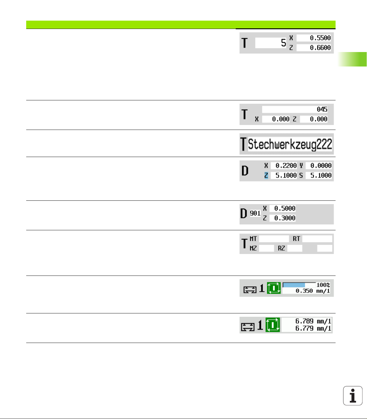
Elements of machine data display
T number display
T number of the inserted tool
Tool compensation values
For all of T displays:
T highlighted in color indicates a driven tool
T number or ID highlighted in color indicates a mirrored tool holder
A letter X/Z of the compensation highlighted in color indicates that a special
compensation is active in the X/Z direction
T ID display
ID of the inserted tool
Tool compensation values
T ID display without compensation values
ID of the inserted tool
Tool compensation
Special compensation only for recessing tools or button tools
Special compensation value in gray means special compensation is not active
A letter X/Z of the compensation highlighted in color indicates that a special
compensation is active in the X/Z direction
3.3 Machine data
Additive compensation
Compensation values in gray means D compensation is not active
Compensation values in black means D compensation is active
Tool life information
"T": Black=global tool life monitoring on; white=global tool life monitoring off
MT, RT active: Monitoring according to tool life
MZ, RZ active: Monitoring according to part quantity
All fields empty: Tool without tool-life monitoring
Slide display and cycle status
Upper field: Setting of the override control
Lower field with white background: Actual feed rate
Lower field with gray background: Programmed feed rate with stationary slide
Slide display and cycle status
Upper field: Programmed feed rate
Lower field: Actual feed rate
HEIDENHAIN CNC PILOT 620/640 79
Page 80

Elements of machine data display
Slide display and cycle status
Upper field: Setting of the override control
Middle field: Programmed feed rate
Lower field: Actual feed rate
Slide display with rear-face machining
If rear-face machining is enabled, the slide number is highlighted in blue.
3.3 Machine data
Spindle display with spindle number, gear range and spindle status
Upper field: Setting of the override control
Lower field: Actual speed or spindle position
For all of the spindle displays:
Spindle symbol: Black means the spindle is enabled; white means it is not.
Numeral in spindle symbol: Gear range
Numeral at right next to the spindle symbol: Spindle number
If a spindle key exists, the number of the selected spindle is highlighted in color.
Spindle status: See "Spindle" on page 82.
Display of the programmed speed in rpm or m/min
Display of the actual speed in rpm
If M19 is active and the machine tool builder has made the setting, when the
spindle is not turning, the display shows the spindle position instead of the
spindle speed.
If a spindle is in slave mode during synchronous operation, the value "0" is
displayed instead of the programmed speed.
Spindle display with spindle number, gear range and spindle status
Upper field: Programmed speed
Lower field: Actual speed or spindle position
Spindle display with spindle number, gear range and spindle status
Upper field: Setting of the override control
Middle field: Programmed speed
Lower field: Actual speed or spindle position
Override display of the active spindle
F: Feed rate
R: Rapid traverse
S: Spindle
Motor utilization: Utilization of the drive motor with respect to the rated torque
Digital axis and spindle motors
Analog axis and spindle motors, if set up by the machine tool builder
80 Machine mode of operation
Page 81

Elements of machine data display
Display of quantity: The quantity is incremented after each M30, M99 or M18
programmed counter pulse.
MP: Default unit quantity
P: Number of finished parts
Display of quantity and job time: The quantity is incremented after each M30,
M99 or M18 programmed counter pulse.
MP: Default unit quantity
P: Number of finished parts
t: Run time of the current program
Sum t: Total time
Display of rear-face machining: Information about rear-face machining is shown
in the RSM display (RSM: Rear Side Machining).
RSM status
Active datum shift of the configured RSM axis
B-axis display: The information displayed about the status of the tilted plane varies
depending on the setting of the machine parameters.
Programmed angular value of the B axis
Display of the current values I, K, U and W
I: Plane reference in X
K: Plane reference in Z
U: Shift in X
W: Shift in Z
3.3 Machine data
The machine data display is configurable by the machine
tool builder. The machine data that appear on your screen
may therefore deviate from the example shown.
Cycle statuses
The CNC PILOT shows the current cycle status with the cycle symbol
(see table at right).
HEIDENHAIN CNC PILOT 620/640 81
Cycle symbols
Status "Cycle ON"
Cycle or program execution is active.
Status "Cycle OFF"
Cycle or program execution is not active.
Page 82

Axis feed rate
F is the identification letter for feed data. Depending on which mode
of the Feed rate soft key is active, data is entered in:
Millimeters per spindle revolution (feed per revolution)
Millimeters per minute (feed per minute).
On the screen, you can tell the type of feed rate from the unit of
measure in the input field.
You can change the feed value with the feed compensation
controller (feed override) (range: 0 % to 150 %).
3.3 Machine data
Spindle
S is the identification letter for spindle data. Depending on which
mode of the Constant speed soft key is active, data is entered in:
Revolutions per minute (constant speed)
Meters per minute (constant surface speed).
The input range is limited by the maximum spindle speed. You define
the speed limitation in the Set T, S, F, dialog box or in DIN
programming with the G26 command. The speed limit remains in
effect until a new speed limit value is programmed.
The speed compensation controller (speed override) allows you to
change the spindle speed (range: 50 % to 150 %).
If you are machining with a constant cutting speed, the
CNC PILOT calculates the spindle speed from the
position of the tool tip. The smaller the diameter of the
tip, the higher the spindle speed. The maximum spindle
speed, however, is never exceeded.
The spindle symbols indicate the direction of spindle
rotation as seen from the point of view of the machinist.
The spindle designation is fixed by the machine tool
builder (see table at right).
Spindle symbols (S display)
Direction of spindle rotation M3
Direction of spindle rotation M4
Spindle stopped
Spindle position-controlled (M19)
C axis on spindle motor is active
Spindle designations
Spindle H0 1
Driven tool 112
82 Machine mode of operation
Page 83

3.4 Setting up a tool list
Machine with turret
The tools used are listed in the turret list. The ID number of the
mounted tool is assigned to every tool holder in the turret.
In the Teach-in cycle you program the turret position as T number.
The tool ID number is automatically entered under "ID."
The turret list can be set up through the TSF menu or directly from the
cycle dialogs in the Teach-in mode.
T turret pocket number
Tool ID (name) is entered automatically.
Open the Turret list. If the cursor is on the ID input
field, the CNC PILOT also automatically opens the
tool list with the entries in the tool database.
Machine with multifix
Machines with multifix tool holders have one tool pocket in which the
tools are changed manually.
T turret pocket number: Always T1
Tool ID (name): Select the ID number from the tool list
Open the Tool list.
3.4 Setting up a tool list
The turret and multifix tool systems can be used together
on one machine. The machine tool builder defines the
number of the multifix pocket.
HEIDENHAIN CNC PILOT 620/640 83
Page 84

Tools in different quadrants
Example: The principal tool carrier of your lathe is in front of the
workpiece (standard quadrant). An additional tool holder is behind
the workpiece.
When CNC PILOT is configured, it is defined for each tool holder
whether the X dimensions and the direction of rotation of circular arcs
are mirrored. In the above-mentioned example the additional tool
holder is assigned the attribute "mirrored."
If this method is used, all machining operations are programmed as
usual—regardless of which tool holder executes the operation. The
simulation also shows all machining operations in the standard
quadrant.
The tools are also described and dimensioned for the standard
quadrant—even if they are inserted in the additional tool holder.
3.4 Setting up a tool list
Mirroring does not become effective until the machining of the
workpiece, i.e. when the additional tool holder is executing the
machining operation.
84 Machine mode of operation
Page 85

Filling the turret list from the database
The turret list indicates the current assignment of the tool carrier. The
turret list can be set up through the TSF menu or directly from the
cycle dialogs in the Teach-in mode.
Look at the entries in the tool database in order to move entries from
the database into the turret assignment list. The CNC PILOT displays
the database entries in the lower area of the screen. The cursor keys
are active in this list.
TRANSFERRING TOOLS FROM THE DATABASE
Press the Tool list soft key (when turret assignment
is open) to open the database.
Select the position in the turret assignment list.
Select and sort the entries in the tool database (see soft-key table at
right)
Use the cursor keys to select the entry in the tool database.
Load the selected tool into the turret assignment list.
3.4 Setting up a tool list
Selecting and sorting entries in the tool
database
The CNC PILOT opens the soft-key
menu to select the desired tool type.
Sorts the tools in the displayed list as
desired according to:
Tool type
Tool ID
Tool orientation
Each time the soft key is pressed it
changes to the next sorting mode.
Switches between ascending and
descending sorting.
Not active here
Closes the tool list.
HEIDENHAIN CNC PILOT 620/640 85
Page 86

Filling the turret list
The turret assignment indicates the current assignment of the tool
carrier. When you set up a turret list, you enter the ID numbers of the
tools.
The turret list can be set up through the TSF menu or directly from the
cycle dialogs in the Teach-in mode. The desired turret pocket is
selected through the cursor keys. You can also set up manual
changing systems in the turret assignment (see "Setting up the holder
for manual change systems" on page 488).
SETTING UP A TOOL LIST
Select Set T, S, F (only available in Manual mode)
3.4 Setting up a tool list
Initiate the cycle dialog
Press the Tool list soft key to activate the turret
assignment table.
Adapt the turret assignment (see soft-key table at right).
Soft keys in turret list
Delete entry
Paste entry from clipboard
Cut out entry and save it in the clipboard
Show entries in the tool database
Switch to next menu
Delete the complete turret list
Back by one menu level
Load the T number and the tool ID
number into the TSF or cycle dialog
Close the turret list without loading the T
number and tool ID into the dialog box.
Changes in the turret list remain
effective.
86 Machine mode of operation
Page 87

Tool call
T is the identification letter for the tool holder. ID designates the tool
ID number. The tool is called by "T" (turret pocket number). The ID
number ID is shown and automatically filled in the dialogs. A turret list
is kept.
In Manual mode, you enter the T number in the TSF dialog box. In
Teach-in mode, "T" and "ID" are cycle parameters.
If a T number is entered in the TSF dialog box with an ID
number that is not defined in the turret list, then the turret
list will be changed accordingly.
Driven tools
Driven tools are defined in the tool description.
The driven tool can be operated with feed per revolution if the tool
spindle drive is equipped with a rotary encoder.
If driven tools are used with constant cutting speed, the spindle
speed is calculated from the tool diameter.
3.4 Setting up a tool list
HEIDENHAIN CNC PILOT 620/640 87
Page 88

Tool life monitoring
If desired, you can have the CNC PILOT monitor tool life or the number
of parts that are produced with a specific tool.
The tool life monitoring function adds the time a tool is used at feed
rate. The quantity monitoring counts the number of finished parts. The
count is compared with the entry in the tool data.
As soon as the tool life expires or the programmed quantity is reached,
the CNC PILOT generates an error message and stops program
execution after the end of the program. If you are working with
program repeats (M99 in DIN programs), the system is stopped after
execution of the current repeat.
For Teach-in programs, the simple tool life monitoring is available.
Here CNC PILOT informs you when a tool is worn out.
In smart.Turn and DIN PLUS programs, you have the choice
between the simple tool life monitoring or the tool life
3.4 Setting up a tool list
monitoring with replacement tools option. If you use
replacement tools, the CNC PILOT automatically inserts the "sister
tool" as soon as the tool is worn-out. The CNC PILOT does not stop
the program run until the last tool of the tool sequence of exchange
is worn out.
You activate/deactivate the tool life management in the parameter
"System/General settings for automatic operation/user parameter tool
life."
The type of monitoring data, the "tool life/remaining tool life" or the
"maximum number of pieces/remaining number of pieces" are
managed in the tool data. They are also edited and displayed in the tool
data (see "Editing tool-life data" on page 483).
You can define replacement tools when setting up the turret. The
"interchange chain" can contain more than one replacement tool. The
interchange chain is part of the NC program (see chapter titled "Tool
Programming" in the "smart.Turn and DIN Programming" User's
Manual.)
You must update the data on tool life and number of
pieces in the "tool management" mode when you replace
the insert of a tool.
88 Machine mode of operation
Page 89

3.5 Machine setup
The machine always requires a few preparations, regardless of
whether you are machining a workpiece manually or automatically. In
Manual mode the following functions are subitems of the Setup menu
item:
Setting the axis values (defining workpiece zero point)
Machine reference (axis reference run)
Setting the protection zone
Defining the tool change position
Setting C-axis values
Defining the workpiece zero point
In the dialog, the distance between the machine zero point and the
workpiece zero point (also know as offset) is shown as XN and ZN. If
the workpiece zero point is changed, the display values will be
changed accordingly.
The workpiece datum can now also be set in the direction
of the Z axis using a touch probe. When setting the zero
point, the control checks which type of tool is currently
active. If you select the Workpiece zero point setup
function and a touch probe is inserted, the control
automatically adjusts the input form. Press NC Start to
start the measuring process. Press the Save soft key to
apply the measured value as workpiece zero point in the Z
axis.
3.5 Machine setup
SETTING THE WORKPIECE ZERO POINT
Select Setting up
Select Set axis values
Touch the workpiece zero point (end face)
Define this point as the "workpiece zero point Z"
Enter the distance between the tool and the workpiece zero point as
"measuring point coordinate Z"
The CNC PILOT calculates the workpiece zero
point Z
HEIDENHAIN CNC PILOT 620/640 89
Page 90

Machine zero point Z = workpiece zero point Z
(offset = 0)
This makes it possible to enter the zero point shift
directly in ZN
Homing the axes
3.5 Machine setup
It is possible to home axes that have already been homed. Here you
can select individual axes or all axes simultaneously.
REFERENCE RUN
Select Setting up
Select Set axis values
Press the Machine reference soft key
Press the Z reference soft key
Press the X reference soft key
Or press all soft keys
Press Cycle start for the control to traverse the
reference marks
The CNC PILOT refreshes the position display.
90 Machine mode of operation
Page 91
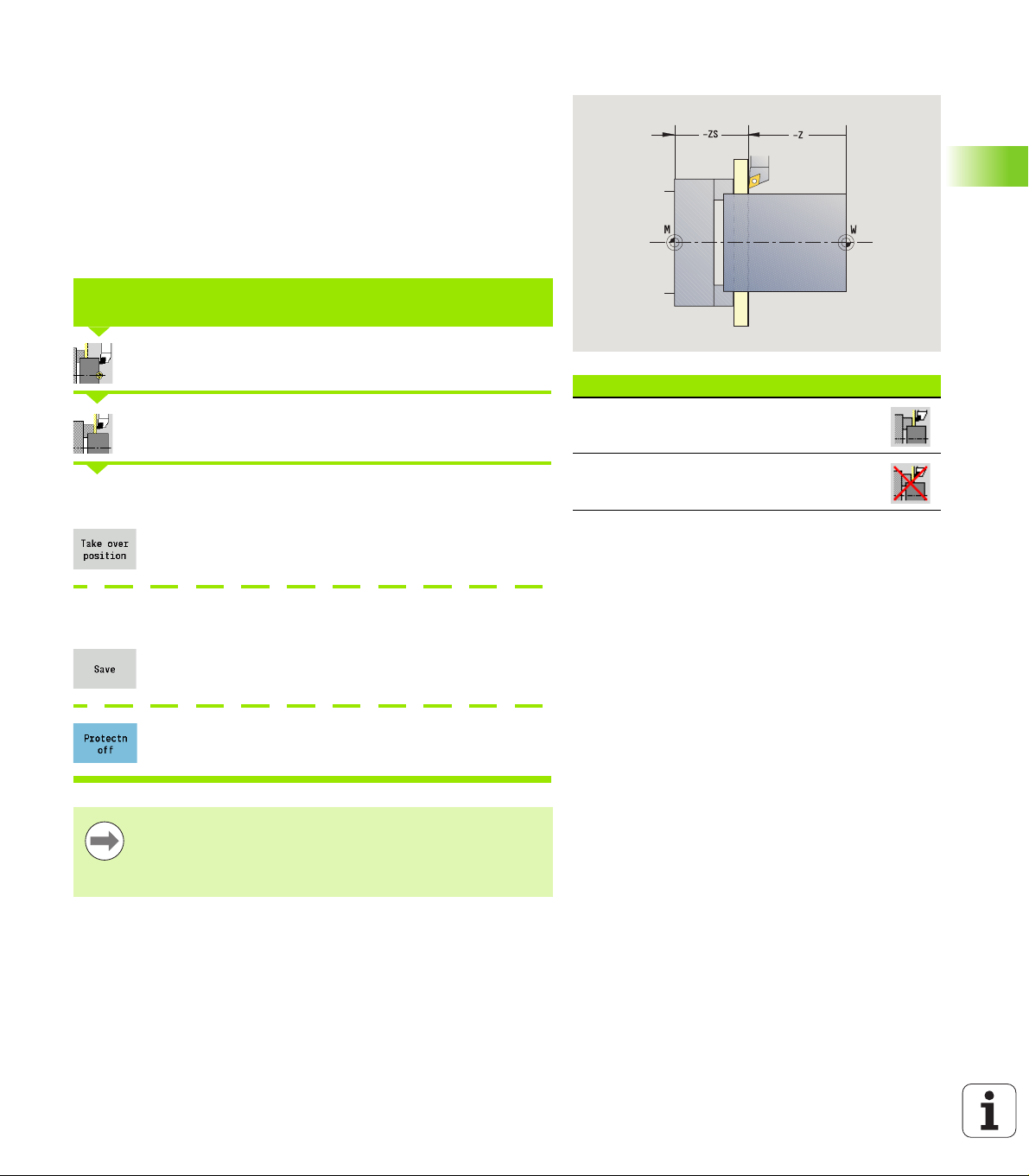
Setting the protection zone
With active protection zone monitoring, the CNC PILOT checks for
every movement whether the protection zone in –Z direction would
be damaged. If it detects such a violation, it stops the axis movement
and generates an error message.
The "Setting the protection zone" setup dialog shows the distance
between the machine zero point and the protection zone in –ZS.
The status of the protection zone monitoring is shown in the machine
display if it has been configured by the machine manufacturer (see
table).
SETTING THE PROTECTION ZONE/SWITCHING OFF THE MONITORING
FUNCTION
Select Setting up
Select Set protection zone
Move the tool with the jog keys or handwheel until it reaches the
protection zone
Use the Take over position soft key to load this
position as protection zone
3.5 Machine setup
Protection zone status
Protective zone monitoring active
Protective zone monitoring not active
Enter the position of the protection zone relative to the workpiece zero
point (field: "Meas. pt. coordin.–Z")
Use the Save soft key to load the entered position as
protection zone
Switch off protective zone monitoring
Protective zone monitoring is not active if the Set
protect zone dialog box is open.
In DIN programming, you deactivate protective zone
monitoring with G60 Q1 and reactivate it with G60.
HEIDENHAIN CNC PILOT 620/640 91
Page 92

Defining the tool change position
With the cycle Move to tool change position or the DIN command
G14, the slide moves to the tool change point. Program the tool
change point far enough away from the workpiece so that the turret
can rotate without collision and the tools do not damage the
workpiece during tool change.
DEFINING THE TOOL CHANGE POSITION
Select Setting up
3.5 Machine setup
Select the tool change point
Move to the tool change position
Move to the tool change point using the jog keys or
the handwheel and load this position as tool change
point
Enter the tool change position directly
Enter the desired tool change position in the X and Z input fields in
machine coordinates (X = radius dimension).
The coordinates of the tool change position are entered
and displayed as the distance between machine zero point
and tool carrier zero point. It is recommended to move to
the tool change point and load the position with the Take
over position soft key.
92 Machine mode of operation
Page 93

Setting C-axis values
The "Set C-axis values" enables you to define a datum shift for the
workpiece spindle:
CN: Position value of the workpiece spindle (display)
C: Datum shift of the C-axis
DEFINING THE ZERO POINT OF THE C AXIS
Select Setting up
Select Set C axis values
Position the C axis
Define the position as the C axis zero point
Enter the zero point shift of the C axis:
Confirm entry for CNC PILOT to calculate the C axis
zero point
3.5 Machine setup
Delete the zero point shift of the C axis
Expanded form view for machines with opposing spindle
If your machine is equipped with an opposing spindle, the CA
parameter is shown. The CA parameter enables you to specify for
which workpiece spindle (main spindle or opposing spindle) entries for
the "Set C-axis value" function are effective.
The active angle offset is shown in the CV parameter. An angle offset
is activated with G905 to match the position of main and opposing
spindle to each other. This may be necessary if both spindles need to
be synchronized for a part transfer. The "Delete CV offset" soft key
enables you to reset an active angle offset.
Additional parameters for machines with opposing spindle:
CV: Display of active angle offset
CA: Selection of C-axis (main spindle or opposing spindle)
HEIDENHAIN CNC PILOT 620/640 93
Page 94

Setting up machine dimensions
The "Set up machine dimensions" function allows you to save any
positions to use these in NC programs.
SETTING UP MACHINE DIMENSIONS
Select Setting up
Select Set up machine dimensions
3.5 Machine setup
Enter the number for the machine dimensions
Assume position of a single axis as machine
dimensions
Assume position of all axes as machine dimensions
Save machine dimensions
94 Machine mode of operation
Page 95
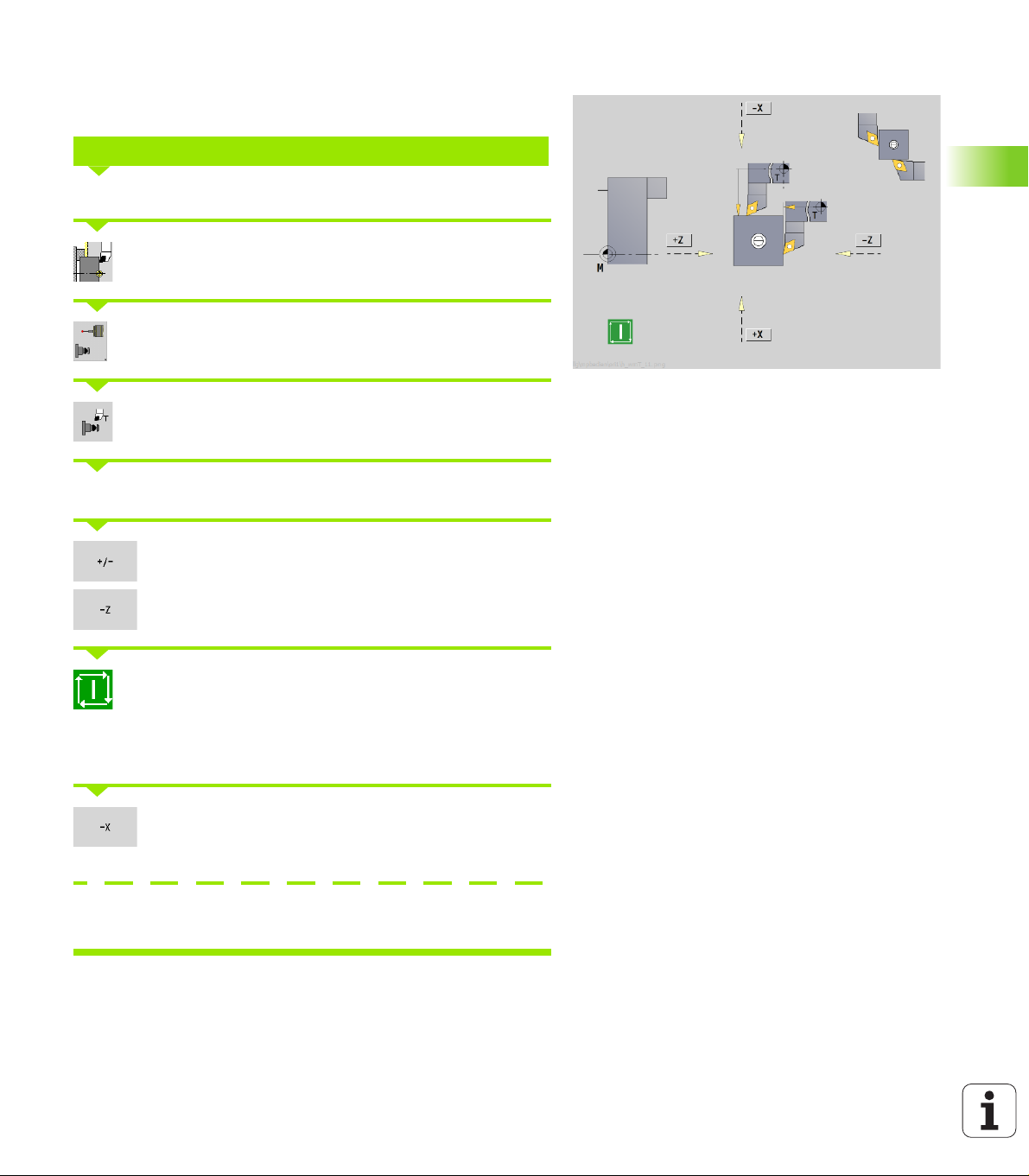
Calibrating the tool touch probe
The "Calibrate the tool touch probe" function enables you to determine
the exact position values of the tool touch probe.
MEASURING THE TOUCH PROBE POSITION
Insert an exactly measured tool or reference tool
Select Setting up
Select touch probe
Select tool touch probe
Pre-position the tool for the first direction of measurement
Set the positive or negative traverse direction
3.5 Machine setup
Press the soft key for this direction (e.g. –Z direction)
Press Cycle START. The tool moves in the direction
of measurement. The position of the touch probe is
measured and saved when the tool touch probe
releases a trigger signal. The tool returns to the
starting point.
Press the "Back" soft key to terminate the calibration
process. The calibration values measured are saved,
or
Pre-position the tool for the next measuring direction and repeat the
procedure (max. 4 measuring directions)
HEIDENHAIN CNC PILOT 620/640 95
Page 96

3.6 Tool measurement
The CNC PILOT supports tool calibration
By touch-off. The setup dimensions are determined by comparing a
tool with an already measured tool.
By touch probe (stationary of swiveling in the working space;
installed by the machine tool builder).
By optical gauge (installed by the machine tool builder).
Calibration by touch-off is always available. If a touch probe or an
optical gauge is installed, select these measuring methods by soft
key.
If the tool dimensions are already known, you can enter the setup
dimensions directly in the "tool management" mode of operation.
3.6 Tool measurement
The compensation values are deleted during tool
measurement.
Please note that for drilling and milling tools the center
is measured.
The tools' type and orientation determine how they are
measured. Note the help graphics.
96 Machine mode of operation
Page 97

Touch off
You measure the dimensions relative to a calibrated tool by "touching
the tool off."
FINDING THE TOOL DIMENSIONS BY TOUCH-OFF WITH THE TOOL
In the tool table, enter the tool you want to measure
Insert the reference tool and enter the T number in
the TSF dialog box
Turn an end face and define this coordinate as the workpiece zero
point
Return to the TSF dialog box and insert the tool to be
measured
Activate Measure tool
Touch the face with the tool
Enter the value 0 for the measuring point coordinate
Z (workpiece zero point) and save it
Turn a measuring diameter
Enter the diameter value as measuring point
coordinate X and save it
For turning tools, enter the cutting edge radius and
load it into the tool table
3.6 Tool measurement
HEIDENHAIN CNC PILOT 620/640 97
Page 98

Touch probe (tool touch probe)
FINDING THE TOOL DIMENSIONS BY USING A TOUCH PROBE
In the tool table, enter the tool you want to measure
Insert a measured tool and enter the T number in the
TSF dialog box
Activate Measure tool
3.6 Tool measurement
Activate Touch probe
Pre-position the tool for the first direction of measurement
Set the positive or negative traverse direction
Press the soft key for this direction (e.g. –Z direction)
Press Cycle START. The tool moves in the direction
of measurement. When it contacts the touch probe,
the control calculates and saves the set-up
dimensions. The tool returns to the starting point.
Pre-position the tool for the second direction of measurement
Press the soft key for this direction (e.g. –X direction)
Press Cycle START. The tool moves in the direction
of measurement. When it contacts the touch probe,
the control calculates and saves the set-up
dimensions.
For turning tools, enter the cutting edge radius and
load it into the tool table
98 Machine mode of operation
Page 99

Optical gauge
FINDING THE TOOL DIMENSIONS BY USING AN OPTICAL GAUGE
In the tool table, enter the tool you want to measure
Insert a measured tool and enter the T number in the
TSF dialog box
Activate Measure tool
Activate optical gauge
Position the tool at the cross hairs of the optical gauge by using the jog
keys or the handwheel
Save the tool dimension in Z
3.6 Tool measurement
Save the tool dimension in X
For turning tools, enter the cutting edge radius and
load it into the tool table
HEIDENHAIN CNC PILOT 620/640 99
Page 100

Tool compensation
The tool compensation in X and Z as well as the special compensation
for recessing tools and button tools compensate for wear of the
cutting edge.
A compensation value must not exceed +/–10 mm.
DEFINING TOOL COMPENSATION
Select Set T, S, F (only available in Manual mode)
3.6 Tool measurement
Press the Tool correct. soft key
Press the X offset for tool (or Z offset)
The compensation values that you determine per
handwheel are now shown in the distance-to-go
display
Transfer the compensation value to the tool table
The T display shows the new compensation value
The distance-to-go display is canceled
DELETING TOOL COMPENSATION VALUES
Select Set T, S, F (only available in Manual mode)
Press the Tool correct. soft key
Press the Delete soft key
Delete compensation value in X (or Z)
100 Machine mode of operation
 Loading...