

Page 1
User’s Manual
HEIDENHAIN
Conversational
Programming
iTNC 530
NC Software
340 490-xx
340 491-xx
340 492-xx
340 493-xx
340 494-xx
English (en)
8/2005
Page 2

Controls on the visual display unit
Split screen layout
Switch between machining or
programming modes
Soft keys for selecting functions in
screen
Switch the soft-key rows
Typewriter keyboard for entering letters and symbols
File names
Comments
ISO
programs
Machine operating modes
Manual Operation
Electronic Handwheel
smarT.NC
Positioning with Manual Data Input (MDI)
Program Run, Single Block
Program Run, Full Sequence
Programming modes
Programming and Editing
Test run
Program/file management, TNC functions
Select or delete programs and files
External data transfer
Define program call, select datum and point tables
MOD Function
Display help texts for NC error messages
Display all current error messages
Pocket calculator
Moving the highlight, going directly to blocks, cycles
and parameter functions
Move highlight
Go directly to blocks, cycles and parameter
functions
Override control knobs for feed rate/spindle speed
1
50
0
50
100
F %
1
50
0
50
100
S %
Programming path movements
Approach/depart contour
FK free contour programming
Straight line
Circle center/pole for polar coordinates
Circular arc with center
Circular arc with radius
Circular arc with tangential connection
Chamfer/corner rounding
Tool functions
Enter and call tool length and radius
Cycles, subprograms and program section
repeats
Define and call cycles
Enter and call labels for subprogramming and
program section repeats
Program stop in a program
Define touch probe cycles
Coordinate axes and numbers: Entering and editing
. . .
Select coordinate axes or
enter them into the program
. . .
Numbers
Decimal point / Reverse algebraic sign
Polar coordinate input/
Incremental dimensions
Q parameter programming/Q parameter status
Assume actual position or values from calculator
Skip dialog questions, delete words
Confirm entry and resume dialog
Conclude block, exit entry
Clear numerical entry or clear TNC error message
Abort dialog, delete program section
Special functions / smarT.NC
Show special functions
smarT.NC: Select next tab on form
smarT.NC: Select first input field in next/
previous frame
Page 3

Page 4

Page 5

HEIDENHAIN iTNC 530 5
TNC Model, Software and Features
This manual describes functions and features provided by TNCs as of
the following NC software numbers.
The suffix E indicates the export version of the TNC. The export
version of the TNC has the following limitations:
Linear movement is possible in no more than 4 axes simultaneously.
The machine tool builder adapts the useable features of the TNC to his
machine by setting machine parameters. Some of the functions
described in this manual may not be among the features provided by
your machine tool.
TNC functions that may not be available on your machine include:
Tool measurement with the TT
Please contact your machine tool builder to become familiar with the
features of your machine.
Many machine manufacturers, as well as HEIDENHAIN, offer
programming courses for the TNCs. We recommend these courses as
an effective way of improving your programming skill and sharing
information and ideas with other TNC users.
TNC model NC software number
iTNC 530 340 490-02
iTNC 530 E 340 491-02
iTNC 530 340 492-02
iTNC 530 E 340 493-02
iTNC 530 programming station 340 494-02
User’s Manual:
All TNC functions that have no connection with touch
probes are described in the User's Manual of the
iTNC 530. Please contact HEIDENHAIN if you need a copy
of this User’s Manual. ID number: 533 190-xx
User documentation:
The new smarT.NC operating mode is described in a
separate Pilot. Please contact HEIDENHAIN if you require
a copy of this Pilot. ID number: 533 191-xx.
Page 6

6
Software options
The iTNC 530 features various software options that can be enabled
by you or your machine tool builder. Each option is to be enabled
separately and contains the following respective functions:
Software option 1
Cylinder surface interpolation (Cycles 27, 28, 29 and 39)
Feed rate in mm/min on rotary axes: M116
Tilting the machining plane (Cycle 19, PLANE function and 3-D ROT
soft key in the manual operating mode)
Circle in 3 axes (with tilted working plane)
Software option 2
Block processing time 0.5 ms instead of 3.6 ms
5 axis interpolation
Spline interpolation
3-D machining:
M114: Automatic compensation of machine geometry when
working with tilted axes
M128: Maintaining the position of the tool tip when positioning
with tilted axes (TCPM)
FUNCTION TCPM: Maintaining the position of the tool tip when
positioning with tilted axes (TCPM) in selectable modes.
M144: Compensating the machine’s kinematic configuration for
ACTUAL/NOMINAL positions at end of block
Additional parameters finishing/roughing and tolerance for
rotary axes in Cycle 32 (G62)
LN blocks (3-D compensation)
DXF Converter software option Description
Extract contours from DXF files (R12
format).
page 252
DCM software option Description
Function which monitors areas defined
by the machine manufacturer to
prevent collisions.
page 81
Additional dialog language software
option
Description
Slovenian. page 647
Page 7

HEIDENHAIN iTNC 530 7
Feature content level (upgrade functions)
Along with software options, significant further improvements of the
TNC software are managed via the Feature Content Level. Functions
subject to the FCL are not available simply by updating the software
on your TNC. These functions are identified in the manual with FCL n,
where n indicates the sequential number of the feature content level.
You can purchse a code number in order to permanently enable the
FCL functions. For more information, contact your machine tool
builder or HEIDENHAIN.
Location of use
The TNC complies with the limits for a Class A device in accordance
with the specifications in EN 55022, and is intended for use primarily
in industrially-zoned areas.
FCL-2 functions Description
3-D line graphics page 128
Virtual tool axis page 80
USB support of block devices (memory
sticks, hard disks, CD-ROM drives)
page 113
Filtering of externally created contours page 514
Possibility of assigning different depths
to each subcontour in the contour
formula
page 433
DHCP dynamic IP-address
management
page 617
Touch-probe cycle for global setting of
touch-probe parameters
User's Manual - Touch
Probe Cycles
smarT.NC: Graphic support of block
scan
smarT.NC Pilot
smarT.NC: Coordinate transformation smarT.NC Pilot
smarT.NC: PLANE function smarT.NC Pilot
Page 8

8
Functions included in 340 49x-01 new since the
predecessor versions 340 422-xx and 340 423-xx
A new form-based operating mode, smarT.NC, introduced. These
cycles are described in a separate user's document. In connection
with this the TNC operating panel was enhanced. There are some
new keys available for quicker navigation within smarT.NC (see
“Operating panel” on page 40).
The single-processor versions supports pointing devices (mice) via
the USB interface.
The tooth feed f
z
and feed per revolution fu can now be defined as
alternate feed entries See table “”.
New CENTERING cycle (see “CENTERING (Cycle 240)” on page
305)
New M function M150 for suppressing limit switch messages (see
“Suppress limit switch message: M150” on page 279)
M128 is now also permitted for mid-program startup (see “Mid-
program startup (block scan)” on page 600).
The number of available Q parameters was expanded to 2000 (see
“Principle and Overview” on page 532).
The number of available label numbers was expanded to 1000. Now
label names can be assigned as well (see “Labeling Subprograms
and Program Section Repeats” on page 516).
In the Q parameter functions FN9 to FN12 you can now also assign
label names as jump targets (see “If-Then Decisions with
Q Parameters” on page 540).
Selectively machine points from a point table (see “Hiding single
points from the machining process” on page 299).
The current time is also shown in the additional status display
window (see “General program information” on page 45).
Several columns were added to the tool table (see “Tool table:
Standard tool data” on page 166).
The Test Run can now also be stopped and continued within
machining cycles (see “Running a program test” on page 594).
Page 9

HEIDENHAIN iTNC 530 9
TNC Model, Software and Features
New functions with 340 49x-02
DXF files can be opened directly on the TNC, in order to extract
contours into a plain-language program (see “Generating Contour
Programs from DXF Data (Software Option)” on page 252)
3-D line graphics are now available in the Programming and Editing
operating mode (see “3-D Line Graphics (FCL 2 Function)” on page
128)
The active tool-axis direction can now be set as the active machining
direction for manual operation (see “Setting the current tool-axis
direction as the active machining direction (FCL 2 function)” on page
80)
The machine manufacturer can now define any areas on the
machine for collision monitoring (see “Dynamic Collision Monitoring
(Software Option)” on page 81)
Instead of the spindle speed S you can now define the cutting speed
Vc in m/min (see “Calling tool data” on page 175)
The TNC can now display freely definable tables in the familiar table
view or as forms (see “Switching between table and form view” on
page 196)
The function for converting FK programs to H was expanded.
Programs can now also be output in linearized format (see
“Converting FK programs into HEIDENHAIN conversational format”
on page 236)
You can filter contours that were created using external
programming systems (see “Filtering Contours (FCL 2 Function)”
on page 514)
For contours which you connect via the contour formula, you can
now assign separate machining depths for each subcontour (see
“Defining contour descriptions” on page 433)
The single-processor version now supports not only pointing
devices (mice), but also USB block devices (memory sticks, disk
drives, hard disks, CD-ROM drives) (see “USB devices on the TNC
(FCL 2 function)” on page 113)
Page 10

10
TNC Model, Software and Features
Functions changed in 340 49x-01 since the
predecessor versions 340 422-xx and 340 423-xx
The layouts of the status display and additional status display were
redesigned (see “Status Displays” on page 44).
Software 340 490 no longer supports the small resolution in
combination with the BC 120 screen (see “Visual display unit” on
page 39).
New key layout of the TE 530 B keyboard unit (see “Operating
panel” on page 40)
The entry range for the EULPR precession angle in the PLANE EULER
function was expanded (see “Defining the Machining Plane with
Euler Angles: EULER PLANE” on page 490)
The plane vector in the PLANE EULER function no longer has to be
entered in standardized form (see “Defining the Machining Plane
with Two Vectors: VECTOR PLANE” on page 492)
Positioning behavior of the CYCL CALL PAT function modified (see
“Calling a cycle in connection with point tables” on page 301)
The tool types available for selection in the tool table were increased
in preparation for future functions.
Instead of the last 10, you can now choose from the last 15 selected
files (see “Choosing one of the last files selected” on page 105)
Page 11

HEIDENHAIN iTNC 530 11
TNC Model, Software and Features
Functions changed in 340 49x-02
Access to the preset table was simplified. There are also new
possibilities for entering values in the preset table See table
“Manually saving the datums in the preset table”
In inch-programs, the function M136 (feed rate in 0.1 inch/rev) can
no longer be combined with the function FU
The feed-rate potentiometers of the HR 420 are no longer switched
over automatically when the handwheel is selected. The selection is
made via soft key on the handwheel. In addition, the pop-up window
for the active handwheel was made smaller, in order to improve the
view of the display beneath it (see “Potentiometer settings” on
page 60)
The maximum number of contour elements for SL cycles was
increased to 8192, so that much more complex contours can be
machined (see “SL Cycles” on page 397)
FN16: F-PRINT: The maximum number of Q-parameter values that
can be output per line in the format description file was increased to
32 (see “FN16: F-PRINT: Formatted output of texts or Q parameter
values” on page 548)
The soft keys START and START SINGLE BLOCK in the Program
Test mode of operation were switched, so that the soft-key
alignment is the same in all modes of operation (Programming and
Editing, smarT.NC, Test) (see “Running a program test” on page
594)
The design of the soft keys was revised completely
Page 12

Page 13

HEIDENHAIN iTNC 530 13
Contents
Introduction
1
Manual Operation and Setup
2
Positioning with Manual Data Input
(MDI)
3
Programming: Fundamentals of File
Management, Programming Aids
4
Programming: Tools
5
Programming: Programming Contours
6
Programming: Miscellaneous Functions
7
Programming: Cycles
8
Programming: Special Functions
9
Programming: Subprograms and
Program Section Repeats
10
Programming: Q Parameters
11
Test Run and Program Run
12
MOD Functions
13
Tables and Overviews
14
iTNC 530 with Windows 2000 (Option)
15
Page 14

Page 15

HEIDENHAIN iTNC 530 15
1.1 The iTNC 530 ..... 38
Programming: HEIDENHAIN conversational, smarT.NC and ISO formats ..... 38
Compatibility ..... 38
1.2 Visual Display Unit and Operating Panel ..... 39
Visual display unit ..... 39
Screen layout ..... 39
Operating panel ..... 40
1.3 Modes of Operation ..... 41
Manual operation and electronic handwheel ..... 41
Positioning with Manual Data Input (MDI) ..... 41
Programming and editing ..... 42
Test Run ..... 42
Program Run, Full Sequence and Program Run, Single Block ..... 43
1.4 Status Displays ..... 44
“General” status display ..... 44
Additional status displays ..... 45
1.5 Accessories: HEIDENHAIN 3-D Touch Probes and Electronic Handwheels ..... 49
3-D touch probes ..... 49
HR electronic handwheels ..... 50
1 Introduction ..... 37
Page 16

16
2.1 Switch-On, Switch-Off ..... 52
Switch-on ..... 52
Switch-off ..... 54
2.2 Moving the Machine Axes ..... 55
Note ..... 55
To traverse with the machine axis direction buttons: ..... 55
Incremental jog positioning ..... 56
Traversing with the HR 410 electronic handwheel ..... 57
HR 420 Electronic Handwheel ..... 58
2.3 Spindle Speed S, Feed Rate F and Miscellaneous Functions M ..... 64
Function ..... 64
Entering values ..... 64
Changing the spindle speed and feed rate ..... 65
2.4 Datum Setting (Without a 3-D Touch Probe) ..... 66
Note ..... 66
Preparation ..... 66
Datum setting with axis keys ..... 67
Datum management with the preset table ..... 68
2.5 Tilting the Working Plane (Software Option 1) ..... 75
Application, function ..... 75
Traversing the reference points in tilted axes ..... 76
Setting the datum in a tilted coordinate system ..... 77
Datum setting on machines with rotary tables ..... 77
Datum setting on machines with spindle-head changing systems ..... 77
Position display in a tilted system ..... 78
Limitations on working with the tilting function ..... 78
Activating manual tilting ..... 79
Setting the current tool-axis direction as the active machining direction (FCL 2 function) ..... 80
2.6 Dynamic Collision Monitoring (Software Option) ..... 81
Function ..... 81
Collision monitoring in the manual operating modes ..... 81
Collision monitoring in Automatic operation ..... 83
3.1 Programming and Executing Simple Machining Operations ..... 86
Positioning with Manual Data Input (MDI) ..... 86
Protecting and Erasing Programs in $MDI ..... 88
2 Manual Operation and Setup ..... 51
3 Positioning with Manual Data Input (MDI) ..... 85
Page 17

HEIDENHAIN iTNC 530 17
4.1 Fundamentals ..... 90
Position encoders and reference marks ..... 90
Reference system ..... 90
Reference system on milling machines ..... 91
Polar coordinates ..... 92
Absolute and incremental workpiece positions ..... 93
Setting the datum ..... 94
4.2 File Management: Fundamentals ..... 95
Files ..... 95
Data backup ..... 96
4.3 Working with the file manager ..... 97
Directories ..... 97
Paths ..... 97
Overview: Functions of the File Manager ..... 98
Calling the File Manager ..... 99
Selecting drives, directories and files ..... 100
Creating a new directory (only possible on the drive TNC:\) ..... 102
Copying a single file ..... 103
Copying a directory ..... 105
Choosing one of the last files selected ..... 105
Deleting a file ..... 106
Deleting a directory ..... 106
Tagging files ..... 107
Renaming a file ..... 108
Additional functions ..... 108
Data transfer to or from an external data medium ..... 109
Copying files into another directory ..... 111
The TNC in a Network ..... 112
USB devices on the TNC (FCL 2 function) ..... 113
4.4 Creating and Writing Programs ..... 114
Organization of an NC program in HEIDENHAIN conversational format ..... 114
Defining the blank form – BLK FORM ..... 114
Creating a new part program ..... 115
Programming tool movements in conversational format ..... 117
Actual position capture ..... 119
Editing a program ..... 120
The TNC search function ..... 124
4 Fundamentals of NC, File Management, Programming Aids, Pallet Management ..... 89
Page 18

18
4.5 Interactive Programming Graphics ..... 126
To generate/not generate graphics during programming: ..... 126
Generating a graphic for an existing program ..... 126
Block number display ON/OFF ..... 127
Erase the graphic ..... 127
Magnifying or reducing a detail ..... 127
4.6 3-D Line Graphics (FCL 2 Function) ..... 128
Function ..... 128
Functions of the 3-D line graphics ..... 129
Highlighting NC blocks in the graphics ..... 131
Block number display ON/OFF ..... 131
Erase the graphic ..... 131
4.7 Structuring Programs ..... 132
Definition and applications ..... 132
Displaying the program structure window / Changing the active window ..... 132
Inserting a structuring block in the (left) program window ..... 132
Selecting blocks in the program structure window ..... 132
4.8 Adding Comments ..... 133
Function ..... 133
Entering comments during programming ..... 133
Inserting comments after program entry ..... 133
Entering a comment in a separate block ..... 133
Functions for editing of the comment ..... 134
4.9 Creating Text Files ..... 135
Function ..... 135
Opening and exiting text files ..... 135
Editing texts ..... 136
Deleting and inserting characters, words and lines ..... 137
Editing text blocks ..... 138
Finding text sections ..... 139
4.10 Integrated Pocket Calculator ..... 140
Operation ..... 140
4.11 Immediate Help for NC Error Messages ..... 141
Displaying error messages ..... 141
Display HELP ..... 141
Page 19

HEIDENHAIN iTNC 530 19
4.12 List of all current error messages ..... 142
Function ..... 142
Show error list ..... 142
Window contents ..... 143
4.13 Pallet Management ..... 144
Function ..... 144
Selecting a pallet table ..... 146
Leaving the pallet file ..... 146
Executing the pallet file ..... 147
4.14 Pallet Operation with Tool-Oriented Machining ..... 148
Function ..... 148
Selecting a pallet file ..... 152
Setting up the pallet file with the entry form ..... 153
Sequence of tool-oriented machining ..... 157
Leaving the pallet file ..... 158
Executing the pallet file ..... 158
Page 20

20
5.1 Entering Tool-Related Data ..... 162
Feed rate F ..... 162
Spindle speed S ..... 163
5.2 Tool Data ..... 164
Requirements for tool compensation ..... 164
Tool numbers and tool names ..... 164
Tool length L ..... 164
Tool radius R ..... 165
Delta values for lengths and radii ..... 165
Entering tool data into the program ..... 165
Entering tool data in tables ..... 166
Using an external PC to overwrite individual tool data ..... 171
Pocket table for tool changer ..... 172
Calling tool data ..... 175
Tool change ..... 176
5.3 Tool Compensation ..... 178
Introduction ..... 178
Tool length compensation ..... 178
Tool radius compensation ..... 179
5.4 Three-Dimensional Tool Compensation (Software Option 2) ..... 182
Introduction ..... 182
Definition of a normalized vector ..... 183
Permissible tool forms ..... 184
Using other tools: Delta values ..... 184
3-D compensation without tool orientation ..... 185
Face Milling: 3-D compensation with and without tool orientation ..... 186
Peripheral Milling: 3-D radius compensation with workpiece orientation ..... 188
5.5 Working with Cutting Data Tables ..... 190
Note ..... 190
Applications ..... 190
Table for workpiece materials ..... 191
Table for tool cutting materials ..... 192
Table for cutting data ..... 192
Data required for the tool table ..... 193
Working with automatic speed / feed rate calculation ..... 194
Changing the table structure ..... 195
Switching between table and form view ..... 196
Data transfer from cutting data tables ..... 197
Configuration file TNC.SYS ..... 197
5 Programming: Tools ..... 161
Page 21

HEIDENHAIN iTNC 530 21
6.1 Tool Movements ..... 200
Path functions ..... 200
FK Free Contour Programming ..... 200
Miscellaneous functions M ..... 200
Subprograms and program section repeats ..... 200
Programming with Q parameters ..... 200
6.2 Fundamentals of Path Functions ..... 201
Programming tool movements for workpiece machining ..... 201
6.3 Contour Approach and Departure ..... 205
Overview: Types of paths for contour approach and departure ..... 205
Important positions for approach and departure ..... 205
Approaching on a straight line with tangential connection: APPR LT ..... 208
Approaching on a straight line perpendicular to the first contour point: APPR LN ..... 208
Approaching on a circular path with tangential connection: APPR CT ..... 209
Approaching on a circular arc with tangential connection from a straight line to the contour: APPR LCT ..... 210
Departing on a straight line with tangential connection: DEP LT ..... 211
Departing on a straight line perpendicular to the last contour point: DEP LN ..... 211
Departure on a circular path with tangential connection: DEP CT ..... 212
Departing on a circular arc tangentially connecting the contour and a straight line: DEP LCT ..... 212
6.4 Path Contours—Cartesian Coordinates ..... 213
Overview of path functions ..... 213
Straight Line L ..... 214
Inserting a Chamfer CHF between Two Straight Lines ..... 215
Corner Rounding RND ..... 216
Circle center CC ..... 217
Circular path C around circle center CC ..... 218
Circular path CR with defined radius ..... 219
Circular Path CT with Tangential Connection ..... 220
6.5 Path Contours—Polar Coordinates ..... 225
Overview ..... 225
Polar coordinate origin: Pole CC ..... 226
Straight line LP ..... 227
Circular path CP around pole CC ..... 227
Circular Path CTP with Tangential Connection ..... 228
Helical interpolation ..... 229
6 Programming: Programming Contours ..... 199
Page 22

22
6.6 Path Contours—FK Free Contour Programming ..... 234
Fundamentals ..... 234
Graphics during FK programming ..... 235
Converting FK programs into HEIDENHAIN conversational format ..... 236
Initiating the FK dialog ..... 237
Free programming of straight lines ..... 238
Free programming of circular arcs ..... 238
Input possibilities ..... 239
Auxiliary points ..... 242
Relative data ..... 243
6.7 Contour Movements—Spline Interpolation (Software Option 2) ..... 250
Function ..... 250
6.8 Generating Contour Programs from DXF Data (Software Option) ..... 252
Function ..... 252
Opening a DXF file ..... 252
Basic settings ..... 253
Layer settings ..... 254
Datum specifying ..... 255
Contour selection, saving a contour program ..... 257
Zoom function ..... 258
Page 23

HEIDENHAIN iTNC 530 23
7.1 Entering Miscellaneous Functions M and STOP ..... 260
Fundamentals ..... 260
7.2 Miscellaneous Functions for Program Run Control, Spindle and Coolant ..... 261
Overview ..... 261
7.3 Miscellaneous Functions for Coordinate Data ..... 262
Programming machine-referenced coordinates: M91/M92 ..... 262
Activating the most recently entered datum: M104 ..... 264
Moving to positions in a non-tilted coordinate system with a tilted working plane: M130 ..... 264
7.4 Miscellaneous Functions for Contouring Behavior ..... 265
Smoothing corners: M90 ..... 265
Insert rounding arc between straight lines: M112 ..... 266
Do not include points when executing non-compensated line blocks: M124 ..... 266
Machining small contour steps: M97 ..... 267
Machining open contours: M98 ..... 269
Feed rate factor for plunging movements: M103 ..... 270
Feed rate in millimeters per spindle revolution: M136 ..... 271
Feed rate for circular arcs: M109/M110/M111 ..... 271
Calculating the radius-compensated path in advance (LOOK AHEAD): M120 ..... 272
Superimposing handwheel positioning during program run: M118 ..... 274
Retraction from the contour in the tool-axis direction: M140 ..... 275
Suppressing touch probe monitoring: M141 ..... 276
Delete modal program information: M142 ..... 277
Delete basic rotation: M143 ..... 277
Automatically retract tool from the contour at an NC stop: M148 ..... 278
Suppress limit switch message: M150 ..... 279
7.5 Miscellaneous Functions for Rotary Axes ..... 280
Feed rate in mm/min on rotary axes A, B, C: M116 (software option 1) ..... 280
Shorter-path traverse of rotary axes: M126 ..... 281
Reducing display of a rotary axis to a value less than 360°: M94 ..... 282
Automatic compensation of machine geometry when working with tilted axes: M114 (software option 2) ..... 283
Maintaining the position of the tool tip when positioning with tilted axes (TCPM): M128 (software
option 2) ..... 284
Exact stop at corners with nontangential transitions: M134 ..... 286
Selecting tilting axes: M138 ..... 286
Compensating the machine’s kinematic configuration for ACTUAL/NOMINAL positions at end of block: M144
(software option 2) ..... 287
7 Programming: Miscellaneous Functions ..... 259
Page 24

24
7.6 Miscellaneous Functions for Laser Cutting Machines ..... 288
Principle ..... 288
Output the programmed voltage directly: M200 ..... 288
Output voltage as a function of distance: M201 ..... 288
Output voltage as a function of speed: M202 ..... 289
Output voltage as a function of time (time-dependent ramp): M203 ..... 289
Output voltage as a function of time (time-dependent pulse): M204 ..... 289
Page 25

HEIDENHAIN iTNC 530 25
8.1 Working with Cycles ..... 292
Machine-specific cycles ..... 292
Defining a cycle using soft keys ..... 293
Defining a cycle using the GOTO function ..... 293
Calling cycles ..... 295
Working with the secondary axes U/V/W ..... 297
8.2 Point Tables ..... 298
Function ..... 298
Creating a point table ..... 298
Hiding single points from the machining process ..... 299
Selecting a point table in the program ..... 300
Calling a cycle in connection with point tables ..... 301
8.3 Cycles for Drilling, Tapping and Thread Milling ..... 303
Overview ..... 303
CENTERING (Cycle 240) ..... 305
DRILLING (Cycle 200) ..... 307
REAMING (Cycle 201) ..... 309
BORING (Cycle 202) ..... 311
UNIVERSAL DRILLING (Cycle 203) ..... 313
BACK BORING (Cycle 204) ..... 315
UNIVERSAL PECKING (Cycle 205) ..... 317
BORE MILLING (Cycle 208) ..... 320
TAPPING NEW with floating tap holder (Cycle 206) ..... 322
RIGID TAPPING without a floating tap holder NEW (Cycle 207) ..... 324
TAPPING WITH CHIP BREAKING (Cycle 209) ..... 326
Fundamentals of thread milling ..... 328
THREAD MILLING (Cycle 262) ..... 330
THREAD MILLING/COUNTERSINKING (Cycle 263) ..... 332
THREAD DRILLING/MILLING (Cycle 264) ..... 336
HELICAL THREAD DRILLING/MILLING (Cycle 265) ..... 340
OUTSIDE THREAD MILLING (Cycle 267) ..... 344
8 Programming: Cycles ..... 291
Page 26

26
8.4 Cycles for Milling Pockets, Studs and Slots ..... 353
Overview ..... 353
RECTANGULAR POCKET (Cycle 251) ..... 354
CIRCULAR POCKET (Cycle 252) ..... 359
SLOT MILLING (Cycle 253) ..... 363
CIRCULAR SLOT (Cycle 254) ..... 368
POCKET FINISHING (Cycle 212) ..... 373
STUD FINISHING (Cycle 213) ..... 375
CIRCULAR POCKET FINISHING (Cycle 214) ..... 377
CIRCULAR STUD FINISHING (Cycle 215) ..... 379
SLOT (oblong hole) with reciprocating plunge-cut (Cycle 210) ..... 381
CIRCULAR SLOT (oblong hole) with reciprocating plunge-cut (Cycle 211) ..... 384
8.5 Cycles for Machining Point Patterns ..... 390
Overview ..... 390
CIRCULAR PATTERN (Cycle 220) ..... 391
LINEAR PATTERN (Cycle 221) ..... 393
8.6 SL Cycles ..... 397
Fundamentals ..... 397
Overview of SL Cycles ..... 399
CONTOUR (Cycle 14) ..... 400
Overlapping contours ..... 401
CONTOUR DATA (Cycle 20) ..... 404
PILOT DRILLING (Cycle 21) ..... 405
ROUGH-OUT (Cycle 22) ..... 406
FLOOR FINISHING (Cycle 23) ..... 407
SIDE FINISHING (Cycle 24) ..... 408
CONTOUR TRAIN (Cycle 25) ..... 409
CYLINDER SURFACE (Cycle 27, software option 1) ..... 411
CYLINDER SURFACE slot milling (Cycle 28, software option 1) ..... 413
CYLINDER SURFACE ridge milling (Cycle 29, software option 1) ..... 416
CYLINDER SURFACE outside contour milling (Cycle 39, software option 1) ..... 418
8.7 SL Cycles with Contour Formula ..... 431
Fundamentals ..... 431
Selecting a program with contour definitions ..... 432
Defining contour descriptions ..... 433
Entering a contour formula ..... 434
Overlapping contours ..... 435
Contour machining with SL Cycles ..... 437
8.8 Cycles for Multipass Milling ..... 441
Overview ..... 441
3-D DATA (Cycle 30) ..... 442
MULTIPASS MILLING (Cycle 230) ..... 443
RULED SURFACE (Cycle 231) ..... 445
FACE MILLING (Cycle 232) ..... 448
Page 27

HEIDENHAIN iTNC 530 27
8.9 Coordinate Transformation Cycles ..... 456
Overview ..... 456
Effect of coordinate transformations ..... 456
DATUM SHIFT (Cycle 7) ..... 457
DATUM SHIFT with datum tables (Cycle 7) ..... 458
DATUM SETTING (Cycle 247) ..... 462
MIRROR IMAGE (Cycle 8) ..... 463
CONTOUR (Cycle 10) ..... 465
SCALING FACTOR (Cycle 11) ..... 466
AXIS-SPECIFIC SCALING (Cycle 26) ..... 467
WORKING PLANE (Cycle 19, software option 1) ..... 468
8.10 Special Cycles ..... 476
DWELL TIME (Cycle 9) ..... 476
PROGRAM CALL (Cycle 12) ..... 477
ORIENTED SPINDLE STOP (Cycle 13) ..... 478
TOLERANCE (Cycle 32, software option 2) ..... 479
9.1 The PLANE Function: Tilting the Working Plane (Software Option 1) ..... 482
Introduction ..... 482
Define the PLANE function ..... 484
Position display ..... 484
Reset the PLANE function ..... 485
9.2 Defining the Machining Plane with Space Angles: PLANE SPATIAL ..... 486
Function ..... 486
Input parameters ..... 487
9.3 Defining the Machining Plane with Projection Angles: PROJECTED PLANE ..... 488
Function ..... 488
Input parameters ..... 489
9.4 Defining the Machining Plane with Euler Angles: EULER PLANE ..... 490
Function ..... 490
Input parameters ..... 491
9.5 Defining the Machining Plane with Two Vectors: VECTOR PLANE ..... 492
Function ..... 492
Input parameters ..... 493
9.6 Defining the Machining Plane via Three Points: POINTS PLANE ..... 494
Function ..... 494
Input parameters ..... 495
9.7 Defining the Machining Plane with a Single, Incremental Space Angle: PLANE RELATIVE ..... 496
Function ..... 496
Input parameters ..... 497
Abbreviations used ..... 497
9 Programming: Special Functions ..... 481
Page 28

28
9.8 Specifying the Positioning Behavior of the PLANE Function ..... 498
Overview ..... 498
Automatic positioning: MOVE/TURN/STAY (entry is mandatory) ..... 499
Selection of alternate tilting possibilities: SEQ +/– (entry optional) ..... 502
Selecting the type of transformation (entry optional) ..... 503
9.9 Inclined-Tool Machining in the Tilted Plane ..... 504
Function ..... 504
Inclined-tool machining via incremental traverse of a rotary axis ..... 504
Inclined-tool machining via normal vectors ..... 505
9.10 TCPM FUNCTION (Software Option 2) ..... 506
Function ..... 506
Define TCPM FUNCTION ..... 506
Mode of action of the programmed feed rate ..... 507
Interpretation of the programmed rotary axis coordinates ..... 508
Interpolation type between the starting and end position ..... 509
Reset TCPM FUNCTION ..... 510
9.11 Generate Backward Program ..... 511
Function ..... 511
Prerequisites for the program to be converted ..... 512
Application example ..... 513
9.12 Filtering Contours (FCL 2 Function) ..... 514
Function ..... 514
Page 29

HEIDENHAIN iTNC 530 29
10.1 Labeling Subprograms and Program Section Repeats ..... 516
Labels ..... 516
10.2 Subprograms ..... 517
Operating sequence ..... 517
Programming notes ..... 517
Programming a subprogram ..... 517
Calling a subprogram ..... 517
10.3 Program Section Repeats ..... 518
Label LBL ..... 518
Operating sequence ..... 518
Programming notes ..... 518
Programming a program section repeat ..... 518
Calling a program section repeat ..... 518
10.4 Separate Program as Subprogram ..... 519
Operating sequence ..... 519
Programming notes ..... 519
Calling any program as a subprogram ..... 520
10.5 Nesting ..... 521
Types of nesting ..... 521
Nesting depth ..... 521
Subprogram within a subprogram ..... 521
Repeating program section repeats ..... 522
Repeating a subprogram ..... 523
10 Programming: Subprograms and Program Section Repeats ..... 515
Page 30

30
11.1 Principle and Overview ..... 532
Programming notes ..... 533
Calling Q parameter functions ..... 533
11.2 Part Families—Q Parameters in Place of Numerical Values ..... 534
Example NC blocks ..... 534
Example ..... 534
11.3 Describing Contours through Mathematical Operations ..... 535
Function ..... 535
Overview ..... 535
Programming fundamental operations ..... 536
11.4 Trigonometric Functions ..... 537
Definitions ..... 537
Programming trigonometric functions ..... 538
11.5 Calculating Circles ..... 539
Function ..... 539
11.6 If-Then Decisions with Q Parameters ..... 540
Function ..... 540
Unconditional jumps ..... 540
Programming If-Then decisions ..... 540
Abbreviations used: ..... 541
11.7 Checking and Changing Q Parameters ..... 542
Procedure ..... 542
11.8 Additional Functions ..... 543
Overview ..... 543
FN14: ERROR: Displaying error messages ..... 544
FN15: PRINT: Output of texts or Q parameter values ..... 547
FN16: F-PRINT: Formatted output of texts or Q parameter values ..... 548
FN18: SYS-DATUM READ Read system data ..... 553
FN19: PLC: Transferring values to the PLC ..... 559
FN20: WAIT FOR: NC and PLC synchronization ..... 560
FN 25: PRESET: Setting a new datum ..... 561
FN26:TABOPEN: Opening a freely definable table ..... 562
FN27: TABWRITE: Writing to a freely definable table ..... 562
FN28:TABREAD: Reading a freely definable table ..... 563
11 Programming: Q Parameters ..... 531
Page 31

HEIDENHAIN iTNC 530 31
11.9 Entering Formulas Directly ..... 564
Entering formulas ..... 564
Rules for formulas ..... 566
Programming example ..... 567
11.10 Preassigned Q Parameters ..... 568
Values from the PLC: Q100 to Q107 ..... 568
Active tool radius: Q108 ..... 568
Tool axis: Q109 ..... 568
Spindle status: Q110 ..... 569
Coolant on/off: Q111 ..... 569
Overlap factor: Q112 ..... 569
Unit of measurement for dimensions in the program: Q113 ..... 569
Tool length: Q114 ..... 569
Coordinates after probing during program run ..... 570
Deviation between actual value and nominal value during automatic tool measurement with the TT 130 ..... 570
Tilting the working plane with mathematical angles: Rotary axis coordinates calculated by the TNC ..... 570
Measurement results from touch probe cycles (see also User’s Manual for Touch Probe Cycles) ..... 571
Page 32

32
12.1 Graphics ..... 582
Function ..... 582
Overview of display modes ..... 584
Plan view ..... 584
Projection in 3 planes ..... 585
3-D view ..... 586
Magnifying details ..... 589
Repeating graphic simulation ..... 590
Measuring the machining time ..... 591
12.2 Functions for Program Display ..... 592
Overview ..... 592
12.3 Test run ..... 593
Function ..... 593
12.4 Program Run ..... 596
Function ..... 596
Run a part program ..... 596
Interrupting machining ..... 597
Moving the machine axes during an interruption ..... 598
Resuming program run after an interruption ..... 599
Mid-program startup (block scan) ..... 600
Returning to the contour ..... 602
12.5 Automatic Program Start ..... 603
Function ..... 603
12.6 Optional Block Skip ..... 604
Function ..... 604
Erasing the “/” character ..... 604
12.7 Optional Program-Run Interruption ..... 605
Function ..... 605
12 Test Run and Program Run ..... 581
Page 33

HEIDENHAIN iTNC 530 33
13.1 MOD Function ..... 608
Selecting the MOD functions ..... 608
Changing the settings ..... 608
Exiting the MOD functions ..... 608
Overview of MOD functions ..... 609
13.2 Software Numbers and Option Numbers ..... 610
Function ..... 610
13.3 Code Numbers ..... 611
Function ..... 611
13.4 Loading Service Packs ..... 612
Function ..... 612
13.5 Setting the Data Interfaces ..... 613
Function ..... 613
Setting the RS-232 interface ..... 613
Setting the RS-422 interface ..... 613
Setting the OPERATING MODE of the external device ..... 613
Setting the BAUD RATE ..... 613
Assign ..... 614
Software for data transfer ..... 615
13.6 Ethernet interface ..... 617
Introduction ..... 617
Connection possibilities ..... 617
Connecting the iTNC directly with a Windows PC ..... 618
Configuring the TNC ..... 620
13.7 Configuring PGM MGT ..... 625
Function ..... 625
Changing the PGM MGT setting ..... 625
Dependent files ..... 626
13.8 Machine-Specific User Parameters ..... 628
Function ..... 628
13.9 Showing the Workpiece in the Working Space ..... 629
Function ..... 629
Rotate the entire image ..... 630
13.10 Position Display Types ..... 631
Function ..... 631
13.11 Unit of Measurement ..... 632
Function ..... 632
13.12 Select the Programming Language for $MDI ..... 633
Function ..... 633
13 MOD Functions ..... 607
Page 34

34
13.13 Selecting the Axes for Generating L Blocks ..... 634
Function ..... 634
13.14 Enter the Axis Traverse Limits, Datum Display ..... 635
Function ..... 635
Working without additional traverse limits ..... 635
Find and enter the maximum traverse ..... 635
Datum display ..... 636
13.15 Displaying HELP Files ..... 637
Function ..... 637
Selecting HELP files ..... 637
13.16 Display operating times ..... 638
Function ..... 638
13.17 TeleService ..... 639
Function ..... 639
Calling/exiting TeleService ..... 639
13.18 External Access ..... 640
Function ..... 640
Page 35

HEIDENHAIN iTNC 530 35
14.1 General User Parameters ..... 642
Input possibilities for machine parameters ..... 642
Selecting general user parameters ..... 642
14.2 Pin Layout and Connecting Cable for the Data Interfaces ..... 656
RS-232-C/V.24 interface for HEIDENHAIN devices ..... 656
Non-HEIDENHAIN devices ..... 657
RS-422/V.11 interface ..... 658
Ethernet interface RJ45 socket ..... 658
14.3 Technical Information ..... 659
14.4 Exchanging the Buffer Battery ..... 666
15.1 Introduction ..... 668
End User License Agreement (EULA) for Windows 2000 ..... 668
General Information ..... 668
Specifications ..... 669
15.2 Starting an iTNC 530 Application ..... 670
Logging on to Windows ..... 670
Logging on as a TNC user ..... 670
Logging on as a local administrator ..... 671
15.3 Switching Off the iTNC 530 ..... 672
Fundamentals ..... 672
Logging a user off ..... 672
Exiting the iTNC application ..... 673
Shutting down Windows ..... 674
15.4 Network Settings ..... 675
Prerequisite ..... 675
Adjusting the network settings ..... 675
Controlling access ..... 676
15.5 Specifics About File Management ..... 677
The iTNC drive ..... 677
Data transfer to the iTNC 530 ..... 678
Overview tables ..... 687
Cycles ..... 687
Miscellaneous functions ..... 689
14 Tables and Overviews ..... 641
15 iTNC 530 with Windows 2000 (Option) ..... 667
Page 36

Page 37

Introduction
Page 38

38 1 Introduction
1.1 The iTNC 530
1.1 The iTNC 530
HEIDENHAIN TNC controls are workshop-oriented contouring
controls that enable you to program conventional machining
operations right at the machine in an easy-to-use conversational
programming language. They are designed for milling, drilling and
boring machines, as well as for machining centers. The iTNC 530 can
control up to 12 axes. You can also change the angular position of the
spindle under program control.
An integrated hard disk provides storage for as many programs as you
like, even if they were created off-line. For quick calculations you can
call up the on-screen pocket calculator at any time.
Keyboard and screen layout are clearly arranged in such a way that the
functions are fast and easy to use.
Programming: HEIDENHAIN conversational,
smarT.NC and ISO formats
HEIDENHAIN conversational programming is an especially easy
method of writing programs. Interactive graphics illustrate the
individual machining steps for programming the contour. If a
production drawing is not dimensioned for NC, the HEIDENHAIN FK
free contour programming does the necessary calculations
automatically. Workpiece machining can be graphically simulated
either during or before actual machining.
The smarT.NC operating mode offers TNC beginners an especially
simple possibility to quickly and without much training create
structured conversational dialog programs. Separate user
documentation is available for smarT.NC.
It is also possible to program in ISO format or DNC mode.
You can also enter and test one program while the control is running
another (does not apply to smarT.NC).
Compatibility
The TNC can run all part programs that were written on HEIDENHAIN
controls TNC 150 B and later. In as much as old TNC programs contain
OEM cycles, the iTNC 530 must be adapted to them with the PC
software CycleDesign. For more information, contact your machine
tool builder or HEIDENHAIN.
Page 39

HEIDENHAIN iTNC 530 39
1.2 Visual Display Unit and Operating Panel
1.2 Visual Display Unit and
Operating Panel
Visual display unit
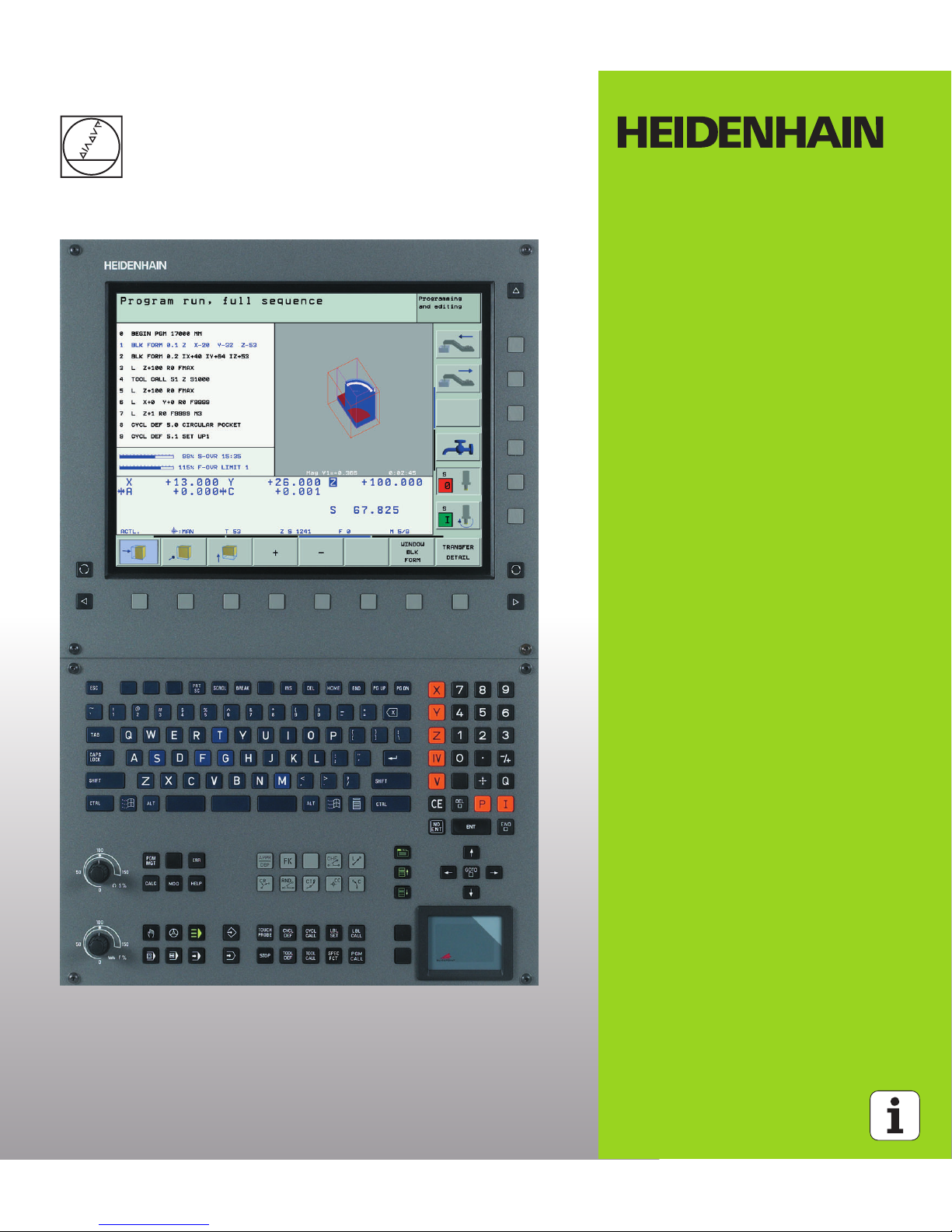
The TNC is delivered with the BF 150 (TFT) color flat-panel display (see
figure).
Screen layout
You select the screen layout yourself: In the PROGRAMMING AND
EDITING mode of operation, for example, you can have the TNC show
program blocks in the left window while the right window displays
programming graphics. You could also display the program structure
in the right window instead, or display only program blocks in one large
window. The available screen windows depend on the selected
operating mode.
To change the screen layout:
Press the SPLIT SCREEN key: The soft-key row
shows the available layout options (see “Modes of
Operation” on page 41).
Select the desired screen layout.
1 Header
When the TNC is on, the selected operating modes are shown in
the screen header: the machining mode at the left and the
programming mode at right. The currently active mode is
displayed in the larger box, where the dialog prompts and TNC
messages also appear (unless the TNC is showing only graphics).
2 Soft keys
In the footer the TNC indicates additional functions in a soft-key
row. You can select these functions by pressing the keys
immediately below them. The lines immediately above the softkey row indicate the number of soft-key rows that can be called
with the black arrow keys to the right and left. The line
representing the active soft-key row is highlighted.
3 Soft-key selection keys
4 Switches the soft-key rows
5 Sets the screen layout
6 Shift key for switchover between machining and programming
modes
7 Soft-key selection keys for machine tool builders
8 Switches soft-key rows for machine tool builders
1
3
1
1
4
4
5
1
6
7
8
2
Page 40

40 1 Introduction
1.2 Visual Display Unit and Operating Panel
Operating panel
The TNC is delivered with the TE 530 operating panel. The figure
shows the controls and displays of the TE 530 keyboard unit.
The functions of the individual keys are described on the inside front
cover.
1 Alphabetic keyboard for entering texts and file names, and for ISO
programming.
Dual-processor version: Additional keys for Windows operation
2 File Management
Calculator
MOD function
HELP function
3 Programming modes
4 Machine operating modes
5 Initiation of programming dialog
6 Arrow keys and GOTO jump command
7 Numerical input and axis selection
8 Touchpad: Only for operating the dual-processor version, soft
keys and smarT.NC
9 smarT.NC navigation keys
Some machine manufacturers do not use the standard
operating panel from HEIDENHAIN. Please refer to your
machine manual in these cases.
Machine panel buttons, e.g. NC START or NC STOP, are
also described in the manual for your machine tool.
1
2
3
5
1
4
6
77
1
79
8
Page 41

HEIDENHAIN iTNC 530 41
1.3 Modes of Operation
1.3 Modes of Operation
Manual operation and electronic handwheel
The Manual Operation mode is required for setting up the machine
tool. In this operating mode you can position the machine axes
manually or by increments, set the datums, and tilt the working plane.
The Electronic Handwheel mode of operation allows you to move the
machine axes manually with the HR electronic handwheel.
Soft keys for selecting the screen layout (select as described
previously)
Positioning with Manual Data Input (MDI)
This mode of operation is used for programming simple traversing
movements, such as for face milling or pre-positioning.
Soft keys for selecting the screen layout
Screen windows Soft key
Positions
Left: positions—Right: status display
Screen windows Soft key
Program
Left: program blocks—Right: status display
Page 42

42 1 Introduction
1.3 Modes of Operation
Programming and editing
In this mode of operation you can write your part programs. The FK
free programming feature, the various cycles and the Q parameter
functions help you with programming and add necessary information.
If desired, the programming graphics or the 3-D line graphics (FCL 2
function) display the programmed traverse paths.
Soft keys for selecting the screen layout
Test Run
In the Test Run mode of operation, the TNC checks programs and
program sections for errors, such as geometrical incompatibilities,
missing or incorrect data within the program or violations of the work
space. This simulation is supported graphically in different display
modes.
Soft keys for selecting the screen layout: see “Program Run, Full
Sequence and Program Run, Single Block” on page 43.
Screen windows Soft key
Program
Left: program blocks, right: program structure
Left: program, right: programming graphics
Left: program, right: 3-D line graphics
Page 43

HEIDENHAIN iTNC 530 43
1.3 Modes of Operation
Program Run, Full Sequence and Program Run,
Single Block
In the Program Run, Full Sequence mode of operation the TNC
executes a part program continuously to its end or to a manual or
programmed stop. You can resume program run after an interruption.
In the Program Run, Single Block mode of operation you execute each
block separately by pressing the machine START button.
Soft keys for selecting the screen layout
Soft keys for selecting the screen layout for pallet tables
Screen windows Soft key
Program
Left: program blocks, right: program structure
Left: program, right: status
Left: program, right: graphics
Graphics
Screen windows Soft key
Pallet table
Left: program, right: pallet table
Left: pallet table, right: status
Left: pallet table, right: graphics
Page 44

44 1 Introduction
1.4 Status Displays
1.4 Status Displays
“General” status display
The status display 1 informs you of the current state of the machine
tool. It is displayed automatically in the following modes of operation:
Program Run, Single Block and Program Run, Full Sequence, except
if the screen layout is set to display graphics only, and
Positioning with Manual Data Input (MDI).
In the Manual mode and Electronic Handwheel mode the status
display appears in the large window.
Information in the status display
Symbol Meaning
Actual or nominal coordinates of the current position.
Machine axes; the TNC displays auxiliary axes in
lower-case letters. The sequence and quantity of
displayed axes is determined by the machine tool
builder. Refer to your machine manual for more
information
The displayed feed rate in inches corresponds to one
tenth of the effective value. Spindle speed S, feed
rate F and active M functions
Program run started
Axis locked.
Axis can be moved with the handwheel.
Axes are moving in a tilted working plane.
Axes are moving under a basic rotation.
PR Number of the active datum from the preset table. If
the datum was set manually, the TNC displays the
text MAN behind the symbol.
1
1
ACTL
.
X Y Z
F S M
Page 45

HEIDENHAIN iTNC 530 45
1.4 Status Displays
Additional status displays
The additional status displays contain detailed information on the
program run. They can be called in all operating modes except for the
Programming and Editing mode of operation.
To switch on the additional status display:
Call the soft-key row for screen layout.
Select the layout option for the additional status
display.
To select an additional status display:
Shift the soft-key rows until the STATUS soft keys
appear.
Select the desired additional status display, e.g.
general program information.
You can choose between several additional status displays with the
following soft keys:
General program information
Soft key Assignment Meaning
1 Name of the active main program
2 Active programs
3 Active machining cycle
4 Circle center CC (pole)
5 Machining time
6 Dwell time counter
7 Current time
4
6
1
2
3
5
6
7
Page 46

46 1 Introduction
1.4 Status Displays
Positions and coordinates
Information on tools
Soft key Assignment Meaning
1 Position display
2 Type of position display, e.g. actual
position
3 Tilt angle of the working plane
4 Angle of a basic rotation
Soft key Assignment Meaning
1 T: Tool number and name
RT: Number and name of a
replacement tool
2 Tool axis
3 Tool lengths and radii
4 Oversizes (delta values) from TOOL
CALL (PGM) and the tool table (TAB)
5 Tool life, maximum tool life (TIME 1)
and maximum tool life for TOOL
CALL (TIME 2)
6 Display of the active tool and the
(next) replacement tool
4
1
3
2
3
2
5
1
4
6
Page 47

HEIDENHAIN iTNC 530 47
1.4 Status Displays
Coordinate transformations
See “Coordinate Transformation Cycles” on page 456.
Program section repeat/Subprograms
Soft key Assignment Meaning
1 Name of the active datum table
2 Active datum number (#), comment
from the active line of the active
datum number (DOC) from Cycle 7
3 Active datum shift (Cycle 7); The TNC
displays an active datum shift in up to
8 axes
4 Mirrored axes (Cycle 8)
5 Active rotation angle (Cycle 10)
6 Active scaling factor/factors (Cycles
11 / 26); The TNC displays an active
scaling factor in up to 6 axes
7 Scaling datum
Soft key Assignment Meaning
1 Active program section repeats with
block number, label number, and
number of programmed repeats/
repeats yet to be run
2 Active subprogram numbers with
block number in which the
subprogram was called and the label
number that was called
6
7
54
3
1
2
1
2
Page 48

48 1 Introduction
1.4 Status Displays
Tool measurement
Active miscellaneous functions M
Soft key Assignment Meaning
1 Number of the tool to be measured
2 Display whether the tool radius or the
tool length is being measured
3 MIN and MAX values of the individual
cutting edges and the result of
measuring the rotating tool (DYN =
dynamic measurement)
4 Cutting edge number with the
corresponding measured value. If the
measured value is followed by an
asterisk, the allowable tolerance in
the tool table was exceeded
Soft key Assignment Meaning
1 List of the active M functions with
fixed meaning
2 List of the active M functions that are
adapted by your machine
manufacturer
2
3
4
1
1
2
Page 49

HEIDENHAIN iTNC 530 49
1.5 Accessories: HEIDENHAIN 3-D Touch Probes and Electronic Handwheels
1.5 Accessories: HEIDENHAIN 3-D
Touch Probes and Electronic
Handwheels
3-D touch probes
With the various HEIDENHAIN 3-D touch probe systems you can:
Automatically align workpieces
Quickly and precisely set datums
Measure the workpiece during program run
Measure and inspect tools
TS 220 and TS 640 touch trigger probes
These touch probes are particularly effective for automatic workpiece
alignment, datum setting and workpiece measurement. The TS 220
transmits the triggering signals to the TNC via cable and is a costeffective alternative for applications where digitizing is not frequently
required.
The TS 640 touch probe (see figure) features infrared transmission of
the triggering signal to the control. This makes it highly convenient for
use on machines with automatic tool changers.
Principle of operation: HEIDENHAIN triggering touch probes feature a
wear resisting optical switch that generates an electrical signal as
soon as the stylus is deflected. This signal is transmitted to the TNC,
which stores the current position of the stylus as an actual value.
All of the touch probe functions are described in a
separate manual. Please contact HEIDENHAIN if you
require a copy of this User’s Manual. Id. Nr.: 329 203-xx.
Page 50

50 1 Introduction
1.5 Accessories: HEIDENHAIN 3-D Touch Probes and Electronic Handwheels
TT 130 tool touch probe for tool measurement
The TT 130 is a triggering 3-D touch probe for tool measurement and
inspection. Your TNC provides three cycles for this touch probe with
which you can measure the tool length and radius automatically either
with the spindle rotating or stopped. The TT 130 features a particularly
rugged design and a high degree of protection, which make it
insensitive to coolants and swarf. The triggering signal is generated by
a wear-resistant and highly reliable optical switch.
HR electronic handwheels
Electronic handwheels facilitate moving the axis slides precisely by
hand. A wide range of traverses per handwheel revolution is available.
Apart from the HR 130 and HR 150 integral handwheels,
HEIDENHAIN also offers the HR 410 and HR 420 portable
handwheels. You will find a detailed description of HR 420 in Chapter
2 of this manual (see “HR 420 Electronic Handwheel” on page 58).
Page 51

Manual Operation and Setup
Page 52

52 2 Manual Operation and Setup
2.1 Switch-On, Switch-Off
2.1 Switch-On, Switch-Off
Switch-on
Switch on the power supply for control and machine. The TNC then
displays the following dialog:
The TNC memory is automatically checked.
TNC message that the power was interrupted—clear
the message.
The PLC program of the TNC is automatically compiled.
Switch on external dc voltage. The TNC checks the
functioning of the EMERGENCY STOP circuit.
Cross the reference points manually in the displayed
sequence: For each axis press the machine START
button, or
Cross the reference points in any sequence: Press
and hold the machine axis direction button for each
axis until the reference point has been traversed.
Switch-on and Traversing the Reference Points can vary
depending on the machine tool. Refer to your machine
manual.
MEMORY TEST
POWER INTERRUPTED
TRANSLATE PLC PROGRAM
RELAY EXT. DC VOLTAGE MISSING
MANUAL OPERATION
TRAVERSE REFERENCE POINTS
If your machine is equipped with absolute encoders, you
can leave out traversing the reference mark. In such a
case, the TNC is ready for operation immediately after the
machine control voltage is switched on.
Page 53

HEIDENHAIN iTNC 530 53
2.1 Switch-On, Switch-Off
The TNC is now ready for operation in the Manual Operation mode.
Traversing the reference point in a tilted working plane
The reference point of a tilted coordinate system can be traversed by
pressing the machine axis direction buttons. The “tilting the working
plane” function must be active in the Manual Operation mode (see
“Activating manual tilting” on page 79). The TNC then interpolates the
corresponding axes.
If available, you can also traverse the axes in the direction of the
current tool axis (see “Setting the current tool-axis direction as the
active machining direction (FCL 2 function)” on page 80).
If one of the two functions that were active before is active now, the
NC START button has no function. The TNC outputs a corresponding
error message.
The reference points need only be traversed if the
machine axes are to be moved. If you intend only to write,
edit or test programs, you can select the Programming
and Editing or Test Run modes of operation immediately
after switching on the control voltage.
You can traverse the reference points later by pressing
the PASS OVER REFERENCE soft key in the Manual
Operation mode.
Make sure that the angle values entered in the menu for
tilting the working plane match the actual angles of the
tilted axis.
If you use this function, then for non-absolute encoders
you must confirm the positions of the rotary axes, which
the TNC displays in a pop-up window. The position
displayed is the last active position of the rotary axes
before switch-off.
Page 54

54 2 Manual Operation and Setup
2.1 Switch-On, Switch-Off
Switch-off
To prevent data being lost at switch-off, you need to shut down the
operating system as follows:
8 Select the Manual operating mode
8 Select the function for shutting down, confirm again
with the YES soft key.
8 When the TNC displays the message Now you can
switch off the TNC in a superimposed window, you
may cut off the power supply to the TNC.
iTNC 530 with Windows 2000: See “Switching Off the
iTNC 530,” page 672.
Inappropriate switch-off of the TNC can lead to data loss.
Page 55

HEIDENHAIN iTNC 530 55
2.2 Moving the Machine Axes
2.2 Moving the Machine Axes
Note
To traverse with the machine axis direction
buttons:
Select the Manual Operation mode
Press the machine axis direction button and hold it as
long as you wish the axis to move, or
Move the axis continuously: Press and hold the
machine axis direction button, then press the
machine START button.
To stop the axis, press the machine STOP button.
You can move several axes at a time with these two methods. You can
change the feed rate at which the axes are traversed with the
F soft key (see “Spindle Speed S, Feed Rate F and Miscellaneous
Functions M” on page 64).
Traversing with the machine axis direction buttons can
vary depending on the machine tool. The machine tool
manual provides further information.
Page 56

56 2 Manual Operation and Setup
2.2 Moving the Machine Axes
Incremental jog positioning
With incremental jog positioning you can move a machine axis by a
preset distance.
Select the Manual or Electronic Handwheel mode of
operation.
Shift the soft-key row.
Select incremental jog positioning: Switch the
INCREMENT soft key to ON
Enter the jog increment in millimeters, i.e. 8 mm.
Press the machine axis direction button as often as
desired.
JOG INCREMENT =
The maximum permissible value for infeed is 10 mm.
16
X
Z
8
8
8
Page 57

HEIDENHAIN iTNC 530 57
2.2 Moving the Machine Axes
Traversing with the HR 410 electronic
handwheel
The portable HR 410 handwheel is equipped with two permissive
buttons. The permissive buttons are located below the star grip.
You can only move the machine axes when a permissive button is
depressed (machine-dependent function).
The HR 410 handwheel features the following operating elements:
The red indicator lights show the axis and feed rate you have selected.
It is also possible to move the machine axes with the handwheel
during a program run if M118 is active.
Procedure:
Select the Electronic Handwheel operating mode.
Press and hold a permissive button.
Select the axis.
Select the feed rate.
Move the active axis in the positive direction, or
Move the active axis in the negative direction.
1 EMERGENCY OFF button
2 Handwheel
3 Permissive buttons
4 Axis address keys
5 Actual-position-capture key
6 Keys for defining the feed rate (slow, medium, fast; the feed rates
are set by the machine tool builder)
7 Direction in which the TNC moves the selected axis
8 Machine function (set by the machine tool builder)
2
4
6
8
1
3
4
5
7
Page 58

58 2 Manual Operation and Setup
2.2 Moving the Machine Axes
HR 420 Electronic Handwheel
Unlike the HR 410, the HR 420 portable handwheel is equipped with
a display. In addition, you can run important setup functions through
the handwheel soft keys, e.g. setting datums or entering and running
M functions.
As soon as you press the handwheel activation key, it activates the
handwheel and deactivates the control panel. This is indicated by a
pop-up window on the TNC screen.
The HR 420 handwheel features the following operating elements:
If M118 is active, it is even possible to move the machine axes with the
handwheel during the program run.
1 EMERGENCY OFF button
2 Handwheel display for status display and function selection
3 Soft keys
4 Axis address keys
5 Handwheel activation key
6 Arrow keys for definition of handwheel sensitivity
7 Direction key by which the TNC moves the selected axis
8 Switch on the spindle (machine-specific M function)
9 Switch off the spindle (machine-specific M function)
10 NC-block creation key
11 NC start
12 NC stop
13 Permissive button
14 Handwheel
15 Spindle speed potentiometer
16 Feed rate potentiometer
Your machine manufacturer can make additional
functions of the HR 420 available. Please refer to your
machine manual.
2
5
7
8
1
3
4
6
7
9
11
12
14
16
15
13
10
6
Page 59

HEIDENHAIN iTNC 530 59
2.2 Moving the Machine Axes
Display
The handwheel display has four lines (see figure). The TNC shows
there the following information:
Select the axis to be moved
You can activate directly through the axis address keys the principal
axes X, Y, Z and two other axes defined by the machine tool builder. If
you machine has more axes, proceed as follows.
8 Press the handwheel soft key F1 (AX): The TNC displays all active
axes on the handwheel display. The active axis blinks
8 Select the desired axis with the handwheel soft key F1 (->) or F2 (<-
) and confirm your selection with F3 (OK).
Set the handwheel sensitivity
The handwheel sensitivity defines the distance that an axis is to move
per handwheel revolution. The sensitivity levels are ready-defined and
are selectable with the handwheel arrow keys (unless incremental jog
is not active).
Selectable sensitivity levels: 0.01/0.02/0.05/0.1/0.2/0.5/1/2/5/10/20
[mm/revolution or degrees/revolution]
1 NOML X+1.563: Type of position display and position of the
selected axis
2 *: STIB (control is in operation)
3 S1000: Current spindle speed
4 F500: Feed rate at which the selected axis is moving
5 E: There is an error
6 3D: Tilted-working-plane function is active
7 2D: Basic rotation function is active
8 RES 5.0: Active handwheel resolution. Distance in mm/rev (°/rev
for rotary axes) that the selected axis moves for one handwheel
revolution
9 STEP ON or OFF: Incremental jog active or inactive. If the function
is active, the TNC also displays the active jog increment
10 Soft key row: Selection of various functions, described in the
following sections
1
3
8
2
4 to 7
9
10
Page 60

60 2 Manual Operation and Setup
2.2 Moving the Machine Axes
Moving the Axes
Activate the handwheel: Press the handwheel key on
the HR 420. Now the TNC is operable only through
the HR 420. A pop-up window stating such appears
on the TNC screen.
Select the desired operating mode via the OPM soft key, if necessary
(see “Changing the modes of operation” on page 62).
If required, press and hold the permissive button
Use the handwheel to select the axis to be moved.
Select the additional axes via soft key
Move the active axis in the positive direction, or
Move the active axis in the negative direction.
Deactivate the handwheel: Press the handwheel key
on the HR 420. Now the TNC can be operated
through the control panel
Potentiometer settings
The potentiometers of the machine operating panel continue to be
active after you have activated the handwheel. If you want to use the
potentiometers on the handwheel, proceed as follows:
8 Press the CTRL and Handwheel keys in the HR 420. The TNC shows
the soft-key menu for selecting the potentiometers on the
handwheel display.
8 Press the HW soft key to activate the handwheel potentiometers.
If you have activated the potentiometers on the handwheel, you must
reactivate the potentiometers of the machine operating panel before
deselecting the handwheel. Proceed as follows:
8 Press the CTRL and Handwheel keys in the HR 420. The TNC shows
the soft-key menu for selecting the potentiometers on the
handwheel display.
8 Press the KBD soft key to activate the potentiometers of the
machine operating panel.
Page 61

HEIDENHAIN iTNC 530 61
2.2 Moving the Machine Axes
Incremental Jog Positioning
With incremental jog positioning the TNC moves the currently active
handwheel axis by a preset distance defined by you.
8 Press the handwheel soft key F2 (STEP)
8 Activate incremental jog positioning: Press handwheel soft key 3
(ON)
8 Select the desired jog increment by pressing the F1 or F2 key. If you
press and hold the respective key, each time it reaches a decimal
value 0 the TNC increases the counting increment by a factor of 10.
If in addition you press the Ctrl key, the counting increment
increases to 1. The smallest possible jog increment is 0.0001 mm.
The largest possible is 10 mm
8 Confirm the selected jog increment with soft key 4 (OK)
8 With the + or – handwheel key, move the active handwheel axis in
the corresponding direction
Entering Miscellaneous Functions M
8 Press the handwheel soft key F3 (MSF)
8 Press the handwheel soft key F1 (M)
8 Select the desired M function number by pressing the F1 or F2 key
8 Execute the M function with the NC start key
Entering the spindle speed S
8 Press the handwheel soft key F3 (MSF)
8 Press the handwheel soft key F2 (S)
8 Select the desired speed by pressing the F1 or F2 key. If you press
and hold the respective key, each time it reaches a decimal value 0
the TNC increases the counting increment by a factor of 10. If in
addition you press the Ctrl key, the counting increment increases to
1000
8 Activate the new speed S with the NC start key
Enter the feed rate F
8 Press the handwheel soft key F3 (MSF)
8 Press the handwheel soft key F3 (F)
8 Select the desired feed rate by pressing the F1 or F2 key. If you
press and hold the respective key, each time it reaches a decimal
value 0 the TNC increases the counting increment by a factor of 10.
If in addition you press the Ctrl key, the counting increment
increases to 1000
8 Confirm the new feed rate F with the handwheel soft key F3 (OK)
Page 62

62 2 Manual Operation and Setup
2.2 Moving the Machine Axes
Datum setting
8 Press the handwheel soft key F3 (MSF)
8 Press the handwheel soft key F4 (PRS)
8 If required, select the axis in which the datum is to be set
8 Reset the axis with the handwheel soft key F3 (OK), or with F1 and
F2 set the desired value and then confirm with F3 (OK). By also
pressing the Ctrl key, you can increase the counting increment to 10
Changing the modes of operation
With the handwheel soft key F4 (OPM), you can use the handwheel to
switch the mode of operation, provided that the current status of the
control allows a mode change.
8 Press the handwheel soft key F4 (OPM)
8 Select the desired operating mode by handwheel soft key
MAN: Manual Operation
MDI: Positioning with Manual Data Input
SGL: Program Run, Single Block
RUN: Program Run, Full Sequence
Generating a complete L Block
8 Select the Positioning with MDI operating mode
8 If required, use the arrow keys on the TNC keyboard to select the
NC block after which the new L block is to be inserted.
8 Actuate handwheel
8 Press the Generate-NC-block handwheel key: The TNC inserts a
complete L block containing all axis positions selected through the
MOD function
Use the MOD function to define the axis values to be
taken into an NC block (see “Selecting the Axes for
Generating L Blocks” on page 634).
If no axes are selected, the TNC displays the error
message No axes selected
Page 63

HEIDENHAIN iTNC 530 63
2.2 Moving the Machine Axes
Features in the Program Run Modes of Operation
You can use the following functions in the Program Run modes of
operation:
NC start (handwheel NC-start key)
NC stop (handwheel NC-stop key)
After the NC-stop key has been pressed: Internal stop (handwheel
soft keys MOP and then STOP)
After the NC-stop key has been pressed: Manual axis traverse
(handwheel soft keys MOP and then MAN)
Returning to the contour, after the axes were moved manually
during a program interruption (handwheel soft keys MOP and then
REPO). Operation is by handwheel soft key, which function similarly
to the control-screen soft keys (see “Returning to the contour” on
page 602)
On/off switch for the Tilted Working Plane function (handwheel soft
keys MOP and then 3D)
Page 64

64 2 Manual Operation and Setup
2.3 Spindle Speed S, Feed Rate F and Miscellaneous Functions M
2.3 Spindle Speed S, Feed Rate F
and Miscellaneous Functions M
Function
In the Manual Operation and Electronic Handwheel operating modes,
you can enter the spindle speed S, feed rate F and the miscellaneous
functions M with soft keys. The miscellaneous functions are
described in Chapter 7 “Programming: Miscellaneous Functions.”
Entering values
Spindle speed S, miscellaneous function M
To enter the spindle speed, press the S soft key.
Enter the desired spindle speed and confirm your
entry with the machine START button.
The spindle speed S with the entered rpm is started with a
miscellaneous function M. Proceed in the same way to enter a
miscellaneous function M.
Feed rate F
After entering a feed rate F, you must confirm your entry with the ENT
key instead of the machine START button.
The following is valid for feed rate F:
If you enter F=0, then the lowest feed rate from MP1020 is effective
F is not lost during a power interruption
The machine tool builder determines which
miscellaneous functions M are available on your control
and what effects they have.
SPINDLE SPEED S =
1000
Page 65

HEIDENHAIN iTNC 530 65
2.3 Spindle Speed S, Feed Rate F and Miscellaneous Functions M
Changing the spindle speed and feed rate
With the override knobs you can vary the spindle speed S and feed
rate F from 0% to 150% of the set value.
The override dial for spindle speed is only functional on
machines with infinitely variable spindle drive.
Page 66

66 2 Manual Operation and Setup
2.4 Datum Setting (Without a 3-D Touch Probe)
2.4 Datum Setting (Without a 3-D
Touch Probe)
Note
You fix a datum by setting the TNC position display to the coordinates
of a known position on the workpiece.
Preparation
8 Clamp and align the workpiece.
8 Insert the zero tool with known radius into the spindle.
8 Ensure that the TNC is showing the actual position values.
For datum setting with a 3-D touch probe, refer to the
Touch Probe Cycles Manual.
Page 67

HEIDENHAIN iTNC 530 67
2.4 Datum Setting (Without a 3-D Touch Probe)
Datum setting with axis keys
Select the Manual Operation mode
Move the tool slowly until it touches (scratches) the
workpiece surface
Select an axis (all axes can also be selected via the
ASCII keyboard)
Zero tool in spindle axis: Set the display to a known
workpiece position (here, 0) or enter the thickness d
of the shim. In the tool axis, offset the tool radius.
Repeat the process for the remaining axes.
If you are using a preset tool, set the display of the tool axis to the
length L of the tool or enter the sum Z=L+d.
Fragile workpiece?
If the workpiece surface must not be scratched, you can
lay a metal shim of known thickness d on it. Then enter a
tool axis datum value that is larger than the desired datum
by the value d.
DATUM SET Z=
Y
X
Z
X
Y
Page 68

68 2 Manual Operation and Setup
2.4 Datum Setting (Without a 3-D Touch Probe)
Datum management with the preset table
Saving the datums in the preset table
The preset table has the name PRESET.PR, and is saved in the directory
TNC:\. PRESET.PR is editable only in the Manual and Electronic
Handwheel modes. In the Programming and Editing mode you can only
read the table, not edit it.
It is permitted to copy the preset table into another directory (for data
backup). Lines that were written by your machine tool builder are also
always write-protected in the copied tables. You therefore cannot edit
them.
Never change the number of lines in the copied tables! That could
cause problems when you want to reactivate the table.
To activate the preset table copied to another directory you have to
copy it back to the directory TNC:\.
You should definitely use the preset table if:
Your machine is equipped with rotary axes (tilting table
or swivel head) and you work with the tilted working
plan function
Your machine is equipped with a spindle-head changing
system
Up to now you have been working with older TNC
controls with REF-based datum tables
You wish to machine identical workpieces that are
differently aligned
The preset table can contain any number of lines
(datums). To optimize the file size and the processing
speed, you should use only as many lines as you need for
datum management.
For safety reasons, new lines can be inserted only at the
end of the preset table.
Page 69

HEIDENHAIN iTNC 530 69
2.4 Datum Setting (Without a 3-D Touch Probe)
There are several methods for saving datums and/or basic rotations in
the preset table:
Through probing cycles in the Manual or El. Handwheel modes (see
User’s Manual, Touch Probe Cycles, Chapter 2)
Through the probing cycles 400 to 402 and 410 to 419 in automatic
mode (see User’s Manual, Touch Probe Cycles, Chapter 3)
Manual entry (see description below)
Basic rotations from the preset table rotate the coordinate
system about the preset, which is shown in the same line
as the basic rotation.
When setting a preset, the TNC checks whether the
position of the tilting axes match the corresponding
values of the 3D ROT menu (depending on the MP
setting). Therefore:
If the “Tilt working plane” function is not active, the
position displays for the rotary axes must = 0° (zero the
rotary axes if necessary).
If the “Tilt working plane” function is active, the
position displays for the rotary axes must match the
angles entered in the 3D ROT menu.
The machine manufacturer can lock any lines in the preset
table in order to place fixed datums there (e.g. a center
point for a rotary table). Such lines in the preset table are
shown in a different color (default: red).
The line 0 in the preset table is write protected. In line 0,
the TNC always saves the datum that you most recently
set manually via the axis keys or via soft key. If the datum
set manually is active, the TNC displays the text PR MAN(0)
in the status display.
If you automatically set the TNC display with the touchprobe cycles for presetting, then the TNC does not store
these values in line 0.
Page 70

70 2 Manual Operation and Setup
2.4 Datum Setting (Without a 3-D Touch Probe)
Manually saving the datums in the preset table
In order to set datums in the preset table, proceed as follows:
Select the Manual Operation mode
Move the tool slowly until it touches (scratches) the
workpiece surface, or position the measuring dial
correspondingly.
Displaying the preset table: The TNC opens the
preset table and sets the cursor to the active table
row.
Select functions for entering the presets: The TNC
display the available possibilities for entry in the softkey row. See the table below for a description of the
entry possibilities.
Select the line in the preset table which you want to
change (the line number is the preset number).
If needed, select the column (axis) in the preset table
which you want to change.
Use the soft keys to select one of the available entry
possibilities (see the following table).
Page 71

HEIDENHAIN iTNC 530 71
2.4 Datum Setting (Without a 3-D Touch Probe)
Function Soft key
Directly the assume the actual position of the
tool (the measuring dial) as the new datum: This
function only saves the datum in the axis whose
field is currently highlighted.
Assign any value to the actual position of the tool
(the measuring dial): This function only saves the
datum in the axis whose field is currently
highlighted. Enter the desired value in the pop-up
window.
Incrementally shift a datum already stored in the
table: This function only saves the datum in the
axis whose field is currently highlighted. Enter
the desired corrective value with the correct sign
in the pop-up window.
Directly enter the new datum without calculation
of the kinematics (axis-specific). Only use this
function if your machine has a rotary table, and
you want to set the datum to the center of the
rotary table by entering 0. This function only
saves the datum in the axis whose field is
currently highlighted. Enter the desired value in
the pop-up window.
Write the currently active datum to a selectable
line in the table: This function saves the datum in
all axes, and then activates the appropriate row in
the table automatically.
Page 72

72 2 Manual Operation and Setup
2.4 Datum Setting (Without a 3-D Touch Probe)
Explanation of values saved in the preset table
Simple machine with three axes without tilting device
The TNC saves in the preset table the distance from the workpiece
datum to the reference point (with the correct algebraic sign).
Machine with swivel head
The TNC saves in the preset table the distance from the workpiece
datum to the reference point (with the correct algebraic sign).
Machine with rotary table
The TNC saves in the preset table the distance from the workpiece
datum to the center of the rotary table (with the correct algebraic
sign).
Machine with rotary table and swivel head
The TNC saves in the preset table the distance from the workpiece
datum to the center of the rotary table.
Keep in mind that moving an indexing feature on your
machine table (realized by changing the kinematics
description) requires you to redefine any workpiece-based
presets.
Page 73

HEIDENHAIN iTNC 530 73
2.4 Datum Setting (Without a 3-D Touch Probe)
Editing the preset table
Editing function in table mode Soft key
Select beginning of table
Select end of table
Select previous page in table
Select next page in table
Select the functions for preset entry
Activate the datum of the selected line of the
preset table
Add the entered number of lines to the end of the
table (2nd soft-key row)
Copy the highlighted field (2nd soft-key row)
Insert the copied field (2nd soft-key row)
Reset the selected line: The TNC enters – in all
columns (2nd soft-key row)
Insert a single line at the end of the table
(2nd soft-key row)
Delete a single line at the end of the table
(2nd soft-key row)
Page 74

74 2 Manual Operation and Setup
2.4 Datum Setting (Without a 3-D Touch Probe)
Activating the datum from the preset table in the Manual
operating mode
Select the Manual Operation mode
Display the preset table
Select the datum number that you want to activate, or
With the GOTO key, select the datum number that
you want to activate. Confirm with the ENT key.
Activate preset
Confirm activation of the datum. The TNC sets the
display and—if defined—the basic rotation
Leave the preset table
Activating the datum from the preset table in an NC program
To activate datums from the preset table during program run, use
Cycle 247. In Cycle 247 you define the number of the datum that you
want to activate (see “DATUM SETTING (Cycle 247)” on page 462).
When activating a datum from the preset table, the TNC
resets all coordinate transformations that were activated
with the following cycles:
Cycle 7, Datum Shift
Cycle 8, Mirroring
Cycle 10, Rotation
Cycle 11, Scaling
Cycle 26, Axis-Specific Scaling
However, the coordinate transformation from Cycle 19,
Tilted Working Plane, remains active.
Page 75

HEIDENHAIN iTNC 530 75
2.5 Tilting the Working Plane (Software Option 1)
2.5 Tilting the Working Plane
(Software Option 1)
Application, function
The TNC supports the tilting functions on machine tools with swivel
heads and/or tilting tables. Typical applications are, for example,
oblique holes or contours in an oblique plane. The working plane is
always tilted around the active datum. The program is written as usual
in a main plane, such as the X/Y plane, but is executed in a plane that
is tilted relative to the main plane.
There are three functions available for tilting the working plane:
3-D ROT soft key in the Manual mode and Electronic Handwheel
mode, see “Activating manual tilting” on page 79.
Tilting under program control, Cycle 19 WORKING PLANE, in the part
program (see “WORKING PLANE (Cycle 19, software option 1)” on
page 468).
Tilting under program control, PLANE function in the part program
(see “The PLANE Function: Tilting the Working Plane
(Software Option 1)” on page 482).
The TNC functions for “tilting the working plane” are coordinate
transformations in which the working plane is always perpendicular to
the direction of the tool axis.
The functions for tilting the working plane are interfaced to
the TNC and the machine tool by the machine tool builder.
With some swivel heads and tilting tables, the machine tool
builder determines whether the entered angles are
interpreted as coordinates of the rotary axes or as angular
components of a tilted plane. Refer to your machine
manual.
X
Z
Y
B
10°
Page 76

76 2 Manual Operation and Setup
2.5 Tilting the Working Plane (Software Option 1)
When tilting the working plane, the TNC differentiates between two
machine types:
Machine with tilting tables
You must tilt the workpiece into the desired position for
machining by positioning the tilting table, for example with an L
block
The position of the transformed tool axis does not change in
relation to the machine-based coordinate system. Thus if you
rotate the table—and therefore the workpiece—by 90° for
example, the coordinate system does not rotate. If you press the
Z+ axis direction button in the Manual Operation mode, the tool
moves in Z+ direction.
In calculating the transformed coordinate system, the TNC
considers only the mechanically influenced offsets of the
particular tilting table (the so-called “translational” components).
Machine with swivel head
You must bring the tool into the desired position for machining by
positioning the swivel head, for example with an L block.
The position of the transformed tool axis changes in relation to the
machine-based coordinate system. Thus if you rotate the swivel
head of your machine—and therefore the tool—in the B axis by
90° for example, the coordinate system rotates also. If you press
the Z+ axis direction button in the Manual Operation mode, the
tool moves in X+ direction of the machine-based coordinate
system.
In calculating the transformed coordinate system, the TNC
considers both the mechanically influenced offsets of the
particular swivel head (the so-called “translational” components)
and offsets caused by tilting of the tool (3-D tool length
compensation).
Traversing the reference points in tilted axes
With tilted axes, you use the machine axis direction buttons to cross
over the reference points. The TNC interpolates the corresponding
axes. Be sure that the function for tilting the working plane is active in
the Manual Operation mode and that the actual angle of the tilted axis
was entered in the menu field.
Page 77

HEIDENHAIN iTNC 530 77
2.5 Tilting the Working Plane (Software Option 1)
Setting the datum in a tilted coordinate system
After you have positioned the rotary axes, set the datum in the same
manner as for a non-tilted system. The behavior of the TNC during
datum setting depends on the settings of machine parameter 7500 in
your kinematics table:
MP 7500, bit 5=0
With an active tilted working plane, the TNC checks during datum
setting in the X, Y and Z axes whether the current coordinates of the
rotary axes agree with the tilt angles that you defined (3D-ROT
menu). If the tilted working plane function is not active, the TNC
checks whether the rotary axes are at 0° (actual positions). If the
positions do not agree, the TNC will display an error message.
MP 7500, bit 5=1
The TNC does not check whether the current coordinates of the
rotary axes (actual positions) agree with the tilt angles that you
defined.
Datum setting on machines with rotary tables
If you use a rotary table to align the workpiece, for example with
probing cycle 403, you must set the table position value to zero after
alignment and before setting the datum in the linear axes X, Y and Z.
The TNC will otherwise display an error message. Cycle 403 provides
you with an input parameter for this purpose (see User’s Manual for
Touch Probe Cycles, “Basic Rotation Compensation via Rotary Axis”).
Datum setting on machines with spindle-head
changing systems
If your machine is equipped with a spindle head changer, you should
use the preset table to manage your datums. Datums saved in preset
tables account for the active machine kinematics (head geometry). If
you exchange heads, the TNC accounts for the new head dimensions
so that the active datum is retained.
Always set a reference point in all three reference axes.
If your machine tool is not equipped with axis control, you
must enter the actual position of the rotary axis in the
menu for manual tilting: The actual positions of one or
several rotary axes must match the entry. Otherwise the
TNC will calculate an incorrect datum.
Page 78

78 2 Manual Operation and Setup
2.5 Tilting the Working Plane (Software Option 1)
Position display in a tilted system
The positions displayed in the status window (ACTL. and NOML.) are
referenced to the tilted coordinate system.
Limitations on working with the tilting function
The probing function for basic rotation is not available if you have
activated the working plane function in the Manual operating mode.
PLC positioning (determined by the machine tool builder) is not
possible.
Page 79

HEIDENHAIN iTNC 530 79
2.5 Tilting the Working Plane (Software Option 1)
Activating manual tilting
To select manual tilting, press the 3-D ROT soft key.
Use the arrow keys to move the highlight to the
Manual Operation menu item.
To activate manual tilting, press the ACTIVE soft key.
Use the arrow keys to position the highlight on the
desired rotary axis.
Enter the tilt angle.
To conclude entry, press the END key.
To reset the tilting function, set the desired operating modes in the
menu “Tilt working plane” to Inactive.
If the tilted working plane function is active and the TNC moves the
machine axes in accordance with the tilted axes, the status display
shows the symbol .
If you activate the “Tilt working plane” function for the Program Run
operating mode, the tilt angle entered in the menu becomes active in
the first block of the part program. If you use Cycle 19 WORKING PLANE
or the PLANE function in the machining program, the angle values
defined there are in effect. Angle values entered in the menu will be
overwritten.
Page 80

80 2 Manual Operation and Setup
2.5 Tilting the Working Plane (Software Option 1)
Setting the current tool-axis direction as the
active machining direction (FCL 2 function)
In the Manual and El. Handwheel modes of operation you can use this
function to move the tool via the external direction keys or with the
handwheel in the direction that the tool axis is currently pointed. Use
this function if
You want to retract the tool in the direction of the tool axis during
program interrupt of a 5-axis machining program.
You want to machine with an inclined tool using the handwheel or
the external direction keys in the Manual operating mode.
To select manual tilting, press the 3-D ROT soft key.
Use the arrow keys to move the highlight to the
Manual Operation menu item.
To activate the current tool-axis direction as the active
machining direction, press the TOOL AXIS soft key.
To conclude entry, press the END key.
To reset the tilting function, set the Manual Operation menu item in
the “Tilt working plane” menu to inactive.
The symbol appears in the status display when the Move in tool-
axis direction function is active.
This function must be enabled by your machine
manufacturer. Refer to your machine manual.
The main axis of the active working plane (X with tool axis
Z) is always in the machine’s permanent main plane (Z/X
with tool axis Z).
This function is even available when you interrupt
program run and want to move the axes manually.
Page 81

HEIDENHAIN iTNC 530 81
2.6 Dynamic Collision Monitoring (Software Option)
2.6 Dynamic Collision Monitoring
(Software Option)
Function
The machine manufacturer can define any objects that are monitored
by the TNC during all machining operations. If two objects monitored
for collision approach each other within a defined distance, the TNC
outputs an error message.
The TNC also monitors the current tool with the length and radius
entered in the tool table for collision (assuming a cylindrical tool).
The dynamic collision monitoring is active in all machine operating
modes, and is indicated by a symbol in the operating mode display.
Collision monitoring in the manual operating
modes
In the Manual and El. Handwheel operating modes, the TNC stops a
motion if two objects monitored for collision approach each other
within a specified distance. In addition, the TNC reduces the feed rate
significantly when the distance to the limit value triggering the error is
less than 5 mm.
There are three zones determining the TNC’s corrective behavior:
Early warning: Two objects monitored for collision are within 14 mm
of each other
Warning: Two objects monitored for collision are within 8 mm of
each other
Error: Two objects monitored for collision are within 2 mm of each
other
The Dynamic Collision Monitoring DCM must be adapted
by the machine manufacturer for the TNC and for the
machine. Refer to your machine manual.
Please note that for certain tools (such as face milling
cutters), the diameter that would cause a diameter can be
greater than the dimensions defined in the toolcompensation data.
Page 82

82 2 Manual Operation and Setup
2.6 Dynamic Collision Monitoring (Software Option)
Early warning zone
Two objects monitored for collision are within 12 to 14 mm of each
other The error message displayed (the machine manufacturer
determines the exact text) always starts with this text string: ]--[
8 Acknowledge the error message with the CE key.
8 Manually traverse the axes out of the danger zone. Pay attention to
the direction of traverse.
8 If applicable, remove the reason for the collision message.
Warning zone
Two objects monitored for collision are within 6 to 8 mm of each other
The error message displayed (the machine manufacturer determines
the exact text) always starts with this text string: ]-[
8 Acknowledge the error message with the CE key.
8 Manually traverse the axes out of the danger zone. Pay attention to
the direction of traverse.
8 If applicable, remove the reason for the collision message.
Error zone
Two objects monitored for collision are less than 2 mm from each
other The error message displayed (the machine manufacturer
determines the exact text) always starts with this text string: ][. In this
state you can only traverse the axes after deactivating collision
monitoring:
8 To select the menu for deactivating collision monitoring, press the
Collision Monitoring soft key (rear soft-key row).
8 Use the arrow keys to select the Manual Operation menu item.
8 To deactivate collision monitoring, press the ENT key, and the
symbol for collision monitoring in the operating mode display starts
to blink.
8 Acknowledge the error message with the CE key.
8 Manually traverse the axes out of the danger zone. Pay attention to
the direction of traverse.
8 If applicable, remove the reason for the collision message.
8 To reactivate collision monitoring, press the ENT key, and the
symbol for collision monitoring in the operating mode display
remains on again.
Page 83

HEIDENHAIN iTNC 530 83
2.6 Dynamic Collision Monitoring (Software Option)
Collision monitoring in Automatic operation
The TNC monitors motions blockwise, i.e. it outputs a warning in the
block which would cause a collision, and interrupts program run. A
reduction of the feed rate, as with Manual operation, does not occur.
The handwheel superpositioning function with M118 is not
possible in combination with collision monitoring.
Page 84

Page 85

Positioning with Manual Data
Input (MDI)
Page 86

86 3 Positioning with Manual Data Input (MDI)
3.1 Programming and Executing Simple Machining Operations
3.1 Programming and Executing
Simple Machining Operations
The Positioning with Manual Data Input mode of operation is
particularly convenient for simple machining operations or prepositioning of the tool. It enables you to write a short program in
HEIDENHAIN conversational programming or in ISO format, and
execute it immediately. You can also call TNC cycles. The program is
stored in the file $MDI. In the Positioning with MDI operating mode,
the additional status displays can also be activated.
Positioning with Manual Data Input (MDI)
Select the Positioning with MDI mode of operation.
Program the file $MDI as you wish.
To start program run, press the machine START key.
Example 1
A hole with a depth of 20 mm is to be drilled into a single workpiece.
After clamping and aligning the workpiece and setting the datum, you
can program and execute the drilling operation in a few lines.
First you pre-position the tool in L blocks (straight-line blocks) to the
hole center coordinates at a setup clearance of 5 mm above the
workpiece surface. Then drill the hole with Cycle 1 PECKING.
Limitation
FK free contour programming, programming graphics and
program run graphics cannot be used. The $MDI file must
not contain a program call (PGM CALL).
Y
X
Z
50
50
0 BEGIN PGM $MDI MM
1 TOOL DEF 1 L+0 R+5
Define tool: zero tool, radius 5
2 TOOL CALL 1 Z S2000
Call tool: tool axis Z
spindle speed 2000 rpm
3 L Z+200 R0 FMAX
Retract tool (F MAX = rapid traverse)
4 L X+50 Y+50 R0 FMAX M3
Move the tool at F MAX to a position above the
hole,
spindle on
5 CYCL DEF 200 DRILLING
Define DRILLING cycle
Q200=5 ;SET-UP CLEARANCE
Set-up clearance of the tool above the hole
Q201=-15 ;DEPTH
Total hole depth (Algebraic sign=working direction)
Page 87

HEIDENHAIN iTNC 530 87
3.1 Programming and Executing Simple Machining Operations
Straight line function L (see “Straight Line L” on page 214), DRILLING
cycle(see “DRILLING (Cycle 200)” on page 307).
Example 2: Correcting workpiece misalignment on machines
with rotary tables
Use the 3-D touch probe to rotate the coordinate system. See “Touch
Probe Cycles in the Manual and Electronic Handwheel Operating
Modes,” section “Compensating workpiece misalignment,” in the
Touch Probe Cycles User’s Manual.
Write down the rotation angle and cancel the Basic Rotation.
Select operating mode: Positioning with MDI.
Select the axis of the rotary table, enter the rotation
angle you wrote down previously and set the feed
rate. For example: L C+2.561 F50
Conclude entry.
Press the machine START button: The rotation of the
table corrects the misalignment.
Q206=250 ;FEED RATE FOR PLNGNG
Feed rate for pecking
Q202=5 ;INFEED DEPTH
Depth of each infeed before retraction
Q210=0 ;DWELL TIME AT TOP
Dwell time after every retraction in seconds
Q203=-10 ;SURFACE COORDINATE
Coordinate of the workpiece surface
Q204=20 ;2ND SET-UP CLEARANCE
Set-up clearance of the tool above the hole
Q211=0.2 ;DWELL TIME AT DEPTH
Dwell time in seconds at the hole bottom
6 CYCL CALL
Call DRILLING cycle
7 L Z+200 R0 FMAX M2
Retract the tool
8 END PGM $MDI MM
End of program
Page 88

88 3 Positioning with Manual Data Input (MDI)
3.1 Programming and Executing Simple Machining Operations
Protecting and Erasing Programs in $MDI
The $MDI file is generally intended for short programs that are only
needed temporarily. Nevertheless, you can store a program, if
necessary, by proceeding as described below:
Select the Programming and Editing mode of
operation.
To call the file manager, press the PGM MGT key
(program management).
Move the highlight to the $MDI file.
To select the file copying function, press the COPY
soft key.
Enter the name under which you want to save the
current contents of the $MDI file.
Copy the file.
To close the file manager, press the END soft key.
Erasing the contents of the $MDI file is done in a similar way: Instead
of copying the contents, however, you erase them with the DELETE
soft key. The next time you select the operating mode Positioning with
MDI, the TNC will display an empty $MDI file.
For further information, see “Copying a single file” on page 103.
TARGET FILE =
If you wish to delete $MDI, then
you must not have selected the Positioning with MDI
mode (not even in the background).
you must not have selected the $MDI file in the
Programming and Editing mode.
BOREHOLE
Page 89

Fundamentals of NC,
File Management,
Programming Aids, Pallet
Management
Page 90

90 4 Fundamentals of NC, File Management, Programming Aids, Pallet Management
4.1 Fundamentals
4.1 Fundamentals
Position encoders and reference marks
The machine axes are equipped with position encoders that register
the positions of the machine table or tool. Linear axes are usually
equipped with linear encoders, rotary tables and tilting axes with angle
encoders.
When a machine axis moves, the corresponding position encoder
generates an electrical signal. The TNC evaluates this signal and
calculates the precise actual position of the machine axis.
If there is an interruption of power, the calculated position will no
longer correspond to the actual position of the machine slide. To
recover this association, incremental position encoders are provided
with reference marks. The scales of the position encoders contain one
or more reference marks that transmit a signal to the TNC when they
are crossed over. From the signal the TNC can re-establish the
assignment of displayed positions to machine positions. For linear
encoders with distance-coded reference marks the machine axes
need to move by no more than 20 mm, for angle encoders by no more
than 20°.
With absolute encoders, an absolute position value is transmitted to
the control immediately upon switch-on. In this way the assignment
of the actual position to the machine slide position is re-established
directly after switch-on.
Reference system
A reference system is required to define positions in a plane or in
space. The position data are always referenced to a predetermined
point and are described through coordinates.
The Cartesian coordinate system (a rectangular coordinate system) is
based on the three coordinate axes X, Y and Z. The axes are mutually
perpendicular and intersect at one point called the datum. A
coordinate identifies the distance from the datum in one of these
directions. A position in a plane is thus described through two
coordinates, and a position in space through three coordinates.
Coordinates that are referenced to the datum are referred to as
absolute coordinates. Relative coordinates are referenced to any other
known position (reference point) you define within the coordinate
system. Relative coordinate values are also referred to as incremental
coordinate values.
Y
X
Z
X (Z,Y)
X
MP
Y
X
Z
Page 91

HEIDENHAIN iTNC 530 91
4.1 Fundamentals
Reference system on milling machines
When using a milling machine, you orient tool movements to the
Cartesian coordinate system. The illustration at right shows how the
Cartesian coordinate system describes the machine axes. The “righthand rule” is illustrated for remembering the three axis directions: the
middle finger points in the positive direction of the tool axis from the
workpiece toward the tool (the Z axis), the thumb points in the positive
X direction, and the index finger in the positive Y direction.
The iTNC 530 can control up to 9 axes. The axes U, V and W are
secondary linear axes parallel to the main axes X, Y and Z, respectively.
Rotary axes are designated as A, B and C. The illustration at lower right
shows the assignment of secondary axes and rotary axes to the main
axes.
+X
+Y
+Z
+X
+Z
+Y
W+
C+
B+
V+
A+
U+
Y
X
Z
Page 92

92 4 Fundamentals of NC, File Management, Programming Aids, Pallet Management
4.1 Fundamentals
Polar coordinates
If the production drawing is dimensioned in Cartesian coordinates, you
also write the part program using Cartesian coordinates. For parts
containing circular arcs or angles it is often simpler to give the
dimensions in polar coordinates.
While the Cartesian coordinates X, Y and Z are three-dimensional and
can describe points in space, polar coordinates are two-dimensional
and describe points in a plane. Polar coordinates have their datum at a
circle center (CC), or pole. A position in a plane can be clearly defined
by the:
Polar Radius, the distance from the circle center CC to the position,
and the
Polar Angle, the size of the angle between the reference axis and
the line that connects the circle center CC with the position.
Setting the pole and the angle reference axis
The pole is set by entering two Cartesian coordinates in one of the
three planes. These coordinates also set the reference axis for the
polar angle PA.
Coordinates of the pole (plane) Reference axis of the angle
X/Y +X
Y/Z +Y
Z/X +Z
X
Y
0°
30
10
CC
PR
PA
1
PA
2
PR
PR
PA
3
X
Z
Y
X
Z
Y
X
Z
Y
Page 93

HEIDENHAIN iTNC 530 93
4.1 Fundamentals
Absolute and incremental workpiece positions
Absolute workpiece positions
Absolute coordinates are position coordinates that are referenced to
the datum of the coordinate system (origin). Each position on the
workpiece is uniquely defined by its absolute coordinates.
Example 1: Holes dimensioned in absolute coordinates
Incremental workpiece positions
Incremental coordinates are referenced to the last programmed
nominal position of the tool, which serves as the relative (imaginary)
datum. When you write a part program in incremental coordinates,
you thus program the tool to move by the distance between the
previous and the subsequent nominal positions. Incremental
coordinates are therefore also referred to as chain dimensions.
To program a position in incremental coordinates, enter the prefix “I”
before the axis.
Example 2: Holes dimensioned in incremental coordinates
Absolute coordinates of hole 4
X = 10 mm
Y = 10 mm
Absolute and incremental polar coordinates
Absolute polar coordinates always refer to the pole and the reference
axis.
Incremental coordinates always refer to the last programmed nominal
position of the tool.
Hole 1 Hole 2 Hole 3
X = 10 mm X = 30 mm X = 50 mm
Y = 10 mm Y = 20 mm Y = 30 mm
Hole 5, referenced to 4 Hole 6, referenced to 5
X = 20 mm X = 20 mm
Y = 10 mm Y = 10 mm
X
Y
30
20
50
3010
10
2
1
3
X
Y
20
10 10
20
10
10
5
4
6
X
Y
0°
30
10
CC
PR
PA
+IPA
PR
PR
+IPA
+IPR
Page 94

94 4 Fundamentals of NC, File Management, Programming Aids, Pallet Management
4.1 Fundamentals
Setting the datum
A production drawing identifies a certain form element of the
workpiece, usually a corner, as the absolute datum. Before setting the
datum, you align the workpiece with the machine axes and move the
tool in each axis to a known position relative to the workpiece. You
then set the TNC display to either zero or a predetermined position
value. This establishes the reference system for the workpiece, which
will be used for the TNC display and your part program.
If the production drawing is dimensioned in relative coordinates,
simply use the coordinate transformation cycles (see “Coordinate
Transformation Cycles” on page 456).
If the production drawing is not dimensioned for NC, set the datum at
a position or corner on the workpiece which is suitable for deducing
the dimensions of the remaining workpiece positions.
The fastest, easiest and most accurate way of setting the datum is by
using a 3-D touch probe from HEIDENHAIN. See “Setting the Datum
with a 3-D Touch Probe” in the Touch Probe Cycles User’s Manual.
Example
The workpiece drawing shows holes (1 to 4) whose dimensions are
shown with respect to an absolute datum with the coordinates X=0
Y=0. The holes (5 to 7) are dimensioned with respect to a relative
datum with the absolute coordinates X=450, Y=750. With the DATUM
SHIFT cycle you can temporarily set the datum to the position X=450,
Y=750, to be able to program the holes (5 to 7) without further
calculations.
Y
X
Z
MAX
MIN
X
Y
325
320
0
450 900
950
150
-150
750
0
300
±
0,1
21
3 4
7
6
5
Page 95

HEIDENHAIN iTNC 530 95
4.2 File Management: Fundamentals
4.2 File Management:
Fundamentals
Files
When you write a part program on the TNC, you must first enter a file
name. The TNC saves the program to the hard disk as a file with the
same name. The TNC can also save texts and tables as files.
The TNC provides a special file management window in which you can
easily find and manage your files. Here you can call, copy, rename and
erase files.
You can manage nearly any number of files with the TNC, at least
25 GB (dual-processor version: 13 GB).
File names
When you store programs, tables and texts as files, the TNC adds an
extension to the file name, separated by a point. This extension
indicates the file type.
File names should not exceed 25 characters, otherwise the TNC
cannot display the entire file name. The characters * \ / “ ? < > .
are not permitted in file names.
Files in the TNC Ty p e
Programs
In HEIDENHAIN format
In ISO format
.H
.I
smarT.NC files
Structured unit program
Contour descriptions
Point tables for machining positions
.HU
.HC
.HP
Tables for
Tools
Tool changers
Pallets
Datums
Points
Presets
Cutting data
Cutting materials, workpiece materials
Dependent data (such as structure items)
.T
.TCH
.P
.D
.PNT
.PR
.CDT
.TAB
.DEP
Texts as
ASCII files .A
Drawing data as
ASCII files .DXF
PROG20 .H
File name File type
Page 96

96 4 Fundamentals of NC, File Management, Programming Aids, Pallet Management
4.2 File Management: Fundamentals
Data backup
We recommend saving newly written programs and files on a PC at
regular intervals.
The TNCremoNT data transmission freeware from HEIDENHAIN is a
simple and convenient method for backing up data stored on the TNC.
You additionally need a data medium on which all machine-specific
data, such as the PLC program, machine parameters, etc., are stored.
Ask your machine manufacturer for assistance, if necessary.
Saving the contents of the entire hard disk (> 2 GB) can
take up to several hours. In this case, it is a good idea to
save the data outside of work hours, e.g. during the night.
Depending on operating conditions (e.g., vibration load),
hard disks generally have a higher failure rate after three to
five years of service. HEIDENHAIN therefore
recommends having the hard disk inspected after three to
five years.
Page 97

HEIDENHAIN iTNC 530 97
4.3 Working with the file manager
4.3 Working with the file manager
Directories
To ensure that you can easily find your files, we recommend that you
organize your hard disk into directories. You can divide a directory into
further directories, which are called subdirectories. With the –/+ key or
ENT you can show or hide the subdirectories.
Directory names
The name of a directory can contain up to 16 characters and does not
have an extension. If you enter more than 16 characters for the
directory name, the TNC will display an error message.
Paths
A path indicates the drive and all directories and subdirectories under
which a file is saved. The individual names are separated by a
backslash “\”.
Example
On drive TNC:\ the subdirectory AUFTR1 was created. Then, in the
directory AUFTR1 the directory NCPROG was created and the part
program PROG1.H was copied into it. The part program now has the
following path:
TNC:\AUFTR1\NCPROG\PROG1.H
The chart at right illustrates an example of a directory display with
different paths.
The TNC can manage up to 6 directory levels!
If you save more than 512 files in one directory, the TNC
no longer sorts them alphabetically!
TNC:\
AUFTR1
NCPROG
WZTAB
A35K941
ZYLM
TESTPROG
HUBER
KAR25T
Page 98

98 4 Fundamentals of NC, File Management, Programming Aids, Pallet Management
4.3 Working with the file manager
Overview: Functions of the File Manager
Function Soft key Page
Copy (and convert) individual files page 103
Select target directory page 103
Display a specific file type page 100
Display the last 10 files that were
selected
page 105
Erase a file or directory page 106
Tag a file page 107
Renaming a file page 108
Protect a file against editing and erasure page 108
Cancel file protection page 108
Manage network drives page 112
Copying a directory page 105
Display all the directories of a particular
drive
Delete directory with all its
subdirectories
page 108
Page 99

HEIDENHAIN iTNC 530 99
4.3 Working with the file manager
Calling the File Manager
Press the PGM MGT key: The TNC displays the file
management window (see figure for default setting.
If the TNC displays a different screen layout, press
the WINDOW soft key.)
The narrow window on the left shows the available drives and
directories. Drives designate devices with which data are stored or
transferred. One drive is the hard disk of the TNC. Other drives are the
interfaces (RS232, RS422, Ethernet), which can be used, for example,
to connect a personal computer. A directory is always identified by a
folder symbol to the left and the directory name to the right. The
control displays a subdirectory to the right of and below its parent
directory. A box with the + symbol in front of the folder symbol
indicates that there are further subdirectories, which can be shown
with the –/+ key or ENT.
The wide window on the right shows you all files that are stored in the
selected directory. Each file is shown with additional information,
illustrated in the table below.
Display Meaning
FILE NAME Name with up to 16 characters and file type
BYTE File size in bytes
STATUS
E
S
M
P
File properties:
Program is selected in the Programming and
Editing mode of operation.
Program is selected in the Test Run mode of
operation.
Program is selected in a program run mode
of operation.
File is protected against editing and erasure.
DATE Date the file was last changed
TIME Time the file was last changed
Page 100

100 4 Fundamentals of NC, File Management, Programming Aids, Pallet Management
4.3 Working with the file manager
Selecting drives, directories and files
Call the File Manager.
With the arrow keys or the soft keys, you can move the highlight to
the desired position on the screen:
Moves the highlight from the left to the right window,
and vice versa.
Moves the highlight up and down within a window.
Moves the highlight one page up or down within a
window.
Step 1: Select drive
Move the highlight to the desired drive in the left window:
To select a drive, press the SELECT soft key, or
Press the ENT key.
Step 2: Select a directory
Move the highlight to the desired directory in the left-hand window—
the right-hand window automatically shows all files stored in the
highlighted directory.
 Loading...