


|
BASIC SPECIFICATIONS |
SUSTAINED POWER OUTPUT: |
60 watts per channel. |
PEAK POWER OUTPUT: |
130 watts per channel. |
HARMONIC DISTORTION: |
Less than 0.5%, 2020,000 cycles per second at 60 watts. |
|
Less than 0.1%, 2020,000 cycles per second at 20 watts. |
|
Unmeasurable at normal listening level. |
INTERMODULATION DISTORTION: |
Less than 0.5% at 60 watts. |
|
Less than 0.2% at 20 watts. |
|
Unmeasurable at normal listening level. |
FREQUENCY RESPONSE: |
60 watts. 1840,000 cycles per second +0, -1.0 db. |
|
20 watts. 1260,000 cycles per second +0, -1.0 db. |
|
1 watt. 2- 80,000 cycles per second +0, -1.0 db. |
OUTPUT IMPEDANCE: |
4, 8, and 16 ohms per channel. |
DAMPING FACTOR: |
Greater than 18. |
FEEDBACK |
Total 30 db. Achieved through multiple loops. |
HUM AND NOISE: |
Better than 90 db below 60 watts. |
POWER SUPPLY: |
Close B+ regulation through use of low Z silicon diode |
|
rectifier power supply. |
SENSITIVITY: |
1.5 volt RMS input for 60 watts. |
STABILITY: |
Unconditionally stable under any load. |
INPUT RECEPTACLES: |
One for each channel. One input for A.C. balance adjustment. |
CONVENIENCE RECEPTACLE: |
One A.C. convenience receptacle. |
CONTROLS: |
Four bias adjust controls. One for each output tube. Two |
|
A.C. balance controls. |
FUSE |
A.C. primary, externally accessible. |
CONSTRUCTION: |
Military terminal board construction with all components held |
|
to rigid tolerances. |
TUBE COMPLEMENT: |
Total 10 tubes, 5 semi-conductors. 6- 12BY7A pentodes; 4- |
|
KT88/6550 beam power pentodes, 4 silicon rectifier diodes, |
|
and 1 selenium rectifier. |
POWER CONSUMPTION: |
350 watts. |
DIMENSIONS: |
16⅜˝ wide x 9˝ high x 11½˝ deep. |
WEIGHT: |
60 lbs. |
FINISH: |
Charcoal brown and gold. |
1
FEATURES
 Use of video output pentodes in all low level stages for exceptionally wide frequency response and low distortion.
 Output stage consists of two KT88/6550’s per channel, conservatively operated in fixed bias, distributed load circuit.
 Multiple feedback loops for increased degree of usable feedback to greatly lower distortion without sacrifi cing stability. 30 db overall.
 Low internal impedance power supply consists of 4 Silicon Rectifier Diodes, choke, and heavy duty electrolytics with potted power transformer for close regulation.
 Extended frequency response. Two octaves above and below the normal range of hearing for smooth, transparent sound.
 Absolute stability with any load!
 Output transformers designed specifically for this amplifier to exacting specifications.
 High power output at the extreme ends of the range enables the amplifier to effortlessly drive any of t oday’s inefficient speakers at any power level. High power rating insures flawless, transparent reproduction at low listening levels.
 Military construction for neat and professional appearance.
 Bias meter to adjust individually the plate current of each KT88/6550 for proper balance and lowest distortion. This insures optimum performance even after aging of the output tubes.
 Unique packaging of components to facilitate identification and to reduce assembly time.
 Use of special glass resistors and heavy duty capacitors for long life and trouble free performance. All components are conservatively rated.
2
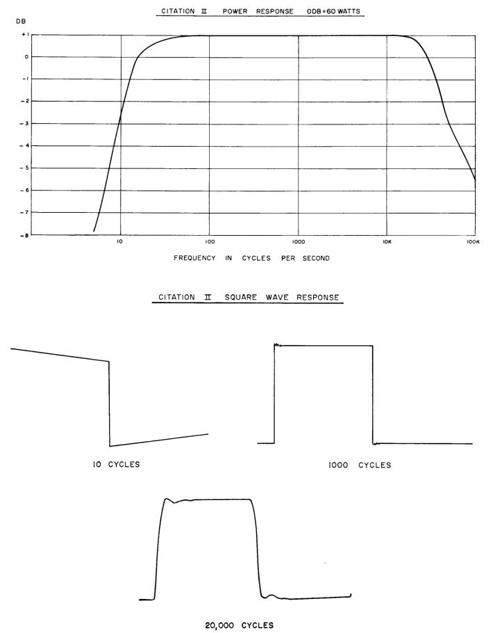
CITATION II CURVES
3

4
INTRODUCTION
This new Citation basic amplifier kit represents the culmination of extensive research and experimenta tion in the technique of kit design. It is meant to satisfy the aspirations of those who insist on nothing short of perfection itself. The keynote is unparalleled performance and there has been no compromise made in the design of this magnificent instrument. Although the Citation II will perform satisfactorily with any high quality preamplifier, it is strongly recommended it be used with the Citation I or Citation IV stereo preamplifiers control center for optimum performance. The Citation I and IV match the superb frequency res ponse and distortion specifications of the Citation II resulting in uncompromising performance.
This instruction manual is written in simple, nontechnical language and if you will take the time to read it thoroughly before starting the actual construction of this kit, your work will be easier and far more accurate. Additional information may be obtained by carefully studying the large fold -out diagrams supplied with this manual. These may be attached to the wall opposite your workbench for easy reference.
After studying the manual, work slowly and carefully. After every ten or fifteen steps, go back over your work to check for possible errors. This will insure proper construction and will afford you the feeling of satis - faction upon completing an amplifier that performs perfectly the first time it is connected.
KEEP THIS INSTRUCTION MANUAL AVAILABLE AT ALL TIMES FOR IT CONTAINS IN - DISPENSABLE TECHNICAL AND SERVICE INFORMATION.
TECHNICAL DESCRIPTION
Extensive listening studies reveal that the behavior of a high fidelity amplifier several octaves above and below the normal range of human hearing distinctly colors the reproduced sound. It has been determined that an amplifier having a wide frequency response at useable power levels below 5 cycles has a tight an d clearly defined low end, particularly in the 40-100 cycles region.
A similar condition applies to the performance of an amplifier in the high frequency spectrum. If an am - plifier limits its high frequency response to slightly above the limit of audibili ty, it may have a tendency toward strident reproduction and poor differentiation of instruments in the high overtones. Conversely, an amplifier which has a frequency response beyond 100,000 cycles without evidence of ringing or instability with reactive loads will offer clean, transparent tone qualities in the higher frequencies with excellent instrument separation.
It is for this reason as well as other considerations that conventional power amplifier design has been by - passed in the general design concept of this basic amplifier.
Current power amplifier design is based upon “single loop” feedback techniques, and linearization is obtained by overall feedback from the voice coil terminals to the cathode of the input tube. Stability problems limit this application to 2026 db of useable feedback, which represents a 101 to 201 reduction in distortion.
Careful listening evaluation of amplifier performance proves conclusively that extremely stable amplifiers with higher degrees of feedback provide a noticeable improvement in sound quality and a definite reduction in listening fatigue. This improvement can be attributed to lower harmonic and intermodulation distortion prod - ucts, more linear phase characteristics, and improved transient response.
A “multiple loop” approach toward increasing the degree of useable feedback is the most logical approach to lower distortion without sacrificing stability. These “multiple loops” become additive if their ratio is adjusted to the relative degree of distortion produced. Thus, if one stage has twice the distortion of another, it should have twice as much feedback around it. Experiment has shown that the equivalent of 30 db overall feedback is safely reached by this approach.
It is essential to have a well regulated power supply in order to maintain clean transient response. The power supply of this amplifier incorporates four Silicon Rectifier Diodes, which together with extremely low copper loss in the power transformer provides regulation equivalent to that of a regulated supply. Leakage inductance in the output transformers has been kept to an absolute minimum, and the distributed capacitance of the primary halves have been carefully balanced against each other to maintain the natural resonances of the output
5
transformers well above 200,000 cycles. The combined use of these special output transformers in conjunction with video pulse amplifier techniques and multiple feedback loops have enabled us to achieve the ex ceptionally wide frequency response of two octaves above and below the normal range of human hearing.
This design employs 2-KT88/6550 beam power pentodes in each channel, driven by video power pentodes used conventionally in pulse amplifiers and wide band industrial equipment such as co mputers. All low frequency coupling networks have been inserted into internal feedback loops, thereby reducing phase distortion to an absolute minimum in the subsonic region. At the same time the high frequency response of the amplifier, exclusive of the output transformer, is flat to the megacycle region.
From the moment you turn this amplifier on and the stylus touches the record with an assured “thump”, you will know you have constructed an exceptional instrument. Critical listening tests will reveal subtleties in your records and tapes you never knew existed, and each performance will prove to be a new experience for you.
UNPACKING
Set aside ample room on your workbench to unpack the contents of this kit. Open the carton carefully and place all of the components on your workbench, separating them into their respective categories. Handle all parts with care, for they may become damaged through carelessness. Check the contents of the carton and folds of the packing material before discarding it.
After all of the parts have been unpacked, check them against the master parts list in this manual to make certain all parts are present and are correct as to type and value. Whenever possible, the values are stamped on the outside of the parts to facilitate identification.
PLEASE NOTIFY YOUR DEALER IMMEDIATELY IF A SHORTAGE OR ERRONEOUS PART IS DISCOVERED.
In the event of visible shipping damage, notify your dealer at once. If the kit was shipped to you, notify the transportation company without delay. Harman-Kardon will cooperate with you in such instances, but please note that only you can recover from the carrier for damages incurred during shipping.
To help us expedite delivery to you, it may occasionally be necessary for us to make minor part substit utions. Before these substitutions are made, they are thoroughly checked to be certain that the replacement is equal to or superior to the original component in every respect. For example, a 50 volt capacitor may be sub stituted for a 25 volt unit. In some instances, a 5% tolerance component may be substituted for a 10% unit. This would provide a component with closer tolerances than required. In every case, these substitutions will not a ffect the performance of the unit.
CONSTRUCTION INFORMATION
Tools Required
Only standard tools are required for the proper assembly of this kit. The most important and frequently used tool will be the soldering iron. It should therefore be a good one. A pencil type iron between 50 and 80 watts or a solder gun up to 100 watts is recommended. You will also require a long-nose pliers, diagonal cutters, screwdriver, sharp knife, solder (rosin core only), and an adjustable wrench. An ohmmeter could be of value but is not essential.
Soldering Technique
Good solder connections are essential for the proper operation of this instrument. An improperly soldered connection or a “cold” solder joint can cause considerable difficulty and is extremely hard to locate. If you have little or no experience with soldering, it is suggested you read the following section carefully before proceeding with the construction of the kit. Practice your soldering on an old terminal strip or tube socket u ntil you are certain you can attain a workable degree of skill. Soldering is not difficult. Merely observe the following rules and precautions:
6
1.USE ONLY ROSIN CORE (NON-CORROSIVE) SOLDER! The solder you purchase should be clearly labeled for radio and television use. The usual composition is 60% tin and 40% lead indicated on the package label as 60/40. Do not use so-called non-corrosive paste. This compound is highly corrosive when heated and will destroy the insulation value of non-conductors and will quickly lead to erratic or degraded performance. It has been our experience that the following solder offer the best results.
Alpha, Cen-tri-core energized rosin 60/40 alloy .062 dia.
Bow, AE 16 rosin core 60/40 alloy .062 dia.
Kester, “44” rosin core 60/40 alloy.
Kester, “Rosin Five” core 60/40 alloy.
Multi-core, Solder #13 SWG (5 core) Flux 364 (rosin) 60/40 alloy.
2.Use a high quality soldering iron in the 50-80 watt range. You may choose either the standard diamond or chisel tip. Always keep the tip clean and properly tinned in accordance with the manufacturer ’s instructions.
3.All terminals and leads must be free from dirt, wax, and corrosion, for solder will not adhere to dirty surfaces. Carefully scrape all terminals and leads which are not clean before applying solder.
4.Solder alone cannot be relied upon for strength. A good mechanical connection must always be made before applying solder. Tinning the leads on resistors and condensers is not always necessary, but is advisable for it helps the solder adhere more readily to the connection.
5.To solder properly, apply the soldering iron to the joint until the joint heats sufficiently to melt the sol der. Apply the solder and hold the iron on the connection until the solder flows freely around and into the connection. Merely melting drops of solder onto the connection is not satisfactory and will result in faulty connections.
6.The general appearance of a connection can indicate if it is properly made. A “cold” solder joint presents a dull and pitted or grainy appearance. A good solder connection should have a bright and smooth appearance. When in doubt as to the condition of a connection, it may be tested by moving the leads slightly to determine if they are loose. Always apply fresh solder when correcting a loose or “cold” solder connection. As a rule, simply reheating the defective joint will not properly do the job.
7.When using your soldering iron, avoid applying excessive heat, as this can result in damage to certain
components. When soldering a joint having a small component connected to it, the part may be protect ed from excessive heat produced by the iron by grasping the lead between the joint and the component with a long-nose pliers. The pliers will then conduct most of the heat away from the component, pre venting overheating and damage.
8.Do not use excessive solder when making a connection. Use only enough solder to cover all leads and to insure a tight connection. Excessive solder may result in the formation of shorts between adjacent terminals, particularly on tube sockets and switch terminals.
9.The step-by-step instructions tell you when to solder and when not to solder a connection. When the lette rs “NS” appear after or during a step, simply wrap or crimp the lead to the terminal and proceed to the next step. When all connections have been completed to this terminal, the solder designation “S” will follow.
7

WARRANTY OF
HARMAN-KARDON CITATION KITS
For a period of 90 days following the original date of purchase, all parts supplied with Harman -Kardon Citation Kits are guaranteed by the manufacturer to be free from defects in material and workmanship when put to normal use and service. This guaranty is specifically limited to the following conditions:
(1) To validate the warranty, the warranty card accompanying each kit must be filled out completely and returned to the factory immediately following the date of purchase.
(2) Harman-Kardon reserves the right to substitute replacement parts for any which may be found defective.
(3) The warranty is effective only as to parts which are defective at the time of sale or become defective as the result of the normal operation during the 90 day period following the date of sa le.
(4) This warranty is limited to those parts which are returned to the factory transportation prepaid, and in the judgment of Harman-Kardon are found defective under the terms of this warranty.
(5) This warranty is specifically void as to any parts in which acid core solder or paste fluxes have been used.
This warranty is in lieu of all other warranties, express or implied, and of all other obligations on the part of Harman-Kardon. Harman-Kardon neither assumes nor authorizes anyone else to assume for it any other liability in connection with the sale of this kit.
Harman-Kardon does not assume liability for damages or injuries incurred during the construction of this
kit.
SERVICE POLICY
If you should have difficulty with this kit and cannot resolve the problem through your own efforts, write directly to us for advice. Harman-Kardon has established a special Citation service division to answer all ques - tions pertinent to the assembly, testing or installation of this instrument. Address all correspondence to:
HARMAN-KARDON, INC.
Citation Kit Division
PLAINVIEW, L. I., NEW YORK
If the factory feels your difficulty may not be easily resolved through your own efforts, you will be notified of the authorized warranty service station nearest your home. These stations are a t your disposal in the event you require assistance. However, please note they will not accept a unit unless previous factory authorization has been given.
If it is necessary to ship your set, pack the unit carefully and return to the warranty station desi gnated by the factory via Railway Express, PREPAID. Pack the kit in a large, rugged container using a substantial quantity of padding and bracing. Attach a tag to the set indicating your name, address and the specific problem. Mentioning the other components in your installation may be of value.
The Harman-Kardon warranty station will inspect and service your kit at a minimum service charge of $10 plus the cost of parts or tubes that are out of warranty, provided the unit has been constructed and completed in accordance with the instructions in this manual.
This special repair offer is available to you for the life of the instrument.
PLEASE NOTE THIS SERVICE APPLIES ONLY TO FULLY COMPLETED INSTRUMENTS. INCOMPLETE AMPLIFIERS OR THOSE THAT HAVE BEEN MODIFIED IN DESIGN WILL NOT BE ACCEPTED. AMPLIFIERS SHOWING EVIDENCE OF ACID CORE SOLDER OR PASTE FLUX WILL SIMILARLY BE REFUSED.
8
ASSEMBLY PROCEDURE
These instructions are presented in a simple, step by step sequence to make assembly and wiring of your amplifier as easy as possible. Please take the time to read each step carefully before actually performing the work. A space is provided to check off each operation and will be helpful in preventing omissions or errors. After every 10 or 15 steps, stop and check your work to insure accuracy.
Note that in the pictorials, each component is identified by a code designation and in addition, each termi nal has also been assigned a number. When the instructions read, “Connect a 100K ½ watt 10% resistor (brown- black-yellow-silver from TB1-1 (S) to TBl-35 (NS)”, it means that the resistor is connected between terminals 1 and 35 on terminal board 1. The abbreviation (S) indicates that the connection should be soldered. The abbreviation (NS) indicates that more than one component is connected to the same terminal and should not be soldered in this operation.
Two types of hook-up wire are used in the assembly of this kit. One type has standard insulation and will be used in all wiring unless otherwise specified. The other type wire has heavier insulation and is used in the B+ and filament lines. The heavy insulation wire will be referred to in all instances as “HI”.
When wire lengths are specified, measure the length on the scale provided on the harness construction jig, In general, the ends of most leads can be stripped back ⅜˝ and any excess bare wire can be clipped off if necessary after installation. The solid wire provided requires no pre-tinning. The stranded wire (transformer leads, etc.) should be twisted and tinned after stripping.
The amplifier is assembled and wired as four separate units:
Electrolytic Bracket
Harness
Terminal Boards
Main Chassis
As each assembly is completed, it should be checked and put aside for later installation. In this way, any errors can be corrected before the construction of the kit has progressed to the final assembly.
The pictorials will facilitate the assembly, location, and wiring of the various component parts and should be referred to at all times. It is suggested that the manual be read and the pictorials studied before starting con - struction of your amplifier.
The mounting hardware supplied with this kit consists of the following:
1.#4-40 screws, nuts, and lockwashers. These are the smallest screws supplied and are used to mount the nine pin miniature sockets.
2.#6-32 x ⅜˝ screws, nuts, and lockwashers. These comprise most of the mounting hardware.
3.1-#6-32 x ¾˝ screw to mount the selenium rectifier.
4.#10 nuts, lockwashers, and 3/32 thick flatwashers to mount the transformers.
5.#8-32 x ⅜˝ screws, nuts, and lockwashers to mount the choke. These are the thickest screws supplied.
RESISTOR HOLDING CARD
The cards on which the resistors and small capacitors are mounted may serve as a convenient holder dur ing construction. Remove the tape by peeling it free from the resistor leads, holding the body of the resistors down to prevent them from being pulled out of the holder. Bend the card on the scored line until it forms a right angle and then use a small piece of tape from the lacing tape roll to hold it in shape.
The card now serves as a pyramid base with the resistor leads pointing upward. This will facilitate identifi - cation and selection of the components as the work progresses.
9
ELECTROLYTIC BRACKET ASSEMBLY
Refer to Pictorial Diagram #1.
Orient bracket so that the U-shaped notches are downward with the larger U-shaped notch to the right.
Check |
|
|
|
|
( |
) |
( |
) Mount selenium rectifier (SR1), using #6-32 x ¾˝ screw through top of bracket. Slip rectifier on |
|
|
|
|
|
screw, negative lug first and engage locating tab in the hole provided on the electrolytic bracke t. Pos- |
|
|
|
|
itive terminal may be identified by red band or plus symbol. Use #6 -32 hardware, lockwasher under |
|
|
|
|
nut. |
( |
) |
( |
) |
Mount small capacitor-insulating wafer as shown at (E). Use #6-32 x ⅜˝ screws, lockwasher under |
|
|
|
|
nut. (Wafer is mounted on top of bracket.) Note orientation. |
( |
) |
( |
) |
Mount large capacitor-insulating wafer and lug strip T6 in the same manner at (A). |
( |
) |
( |
) |
Mount silicon diode holder (T5). Insert screws through holder and bracket. Use #6-32 x ⅜˝ screws, |
|
|
|
|
lockwasher under nut. |
( |
) |
( |
) Mount 20-20 mfd 150 wv cardboard-insulated electrolytic capacitor at (E). Note orientation. Twist |
|
( |
) |
( |
) |
mounting tabs ¼ turn after insertion, to lock in place. |
Mount 50-50 mfd 450 wv electrolytic capacitor at (D) in the same manner, noting orientation. Twist |
||||
|
|
|
|
mounting tabs ¼ turn. |
( |
) |
( |
) Mount single 40 mfd 525 wv electrolytic capacitor at (C) in the same manner, noting orientation. |
|
|
|
|
|
Twist mounting tabs ¼ turn. |
( |
) |
( |
) |
Mount single 200 mfd 250 wv electrolytic capacitor at (B). Note orientation. Twist tabs ¼ turn. |
( |
) |
( |
) Mount single 200 mfd 250 wv electrolytic capacitor with cardboard insulating sleeve at (A). Note |
|
|
|
|
|
orientation. Twist tabs ¼ turn. |
( |
) |
( |
) Insert the four silicon diodes into the clips on the holder (T5) as shown in the pictorial. It is |
|
|
|
|
|
imperative that the silicon diodes are installed in the manner shown in Pictorial 1. Note that the large |
|
|
|
|
disks on SD1 and SD2 are at the right and the large disks on SD3 and SD4 are at the left. |
( |
) |
( |
) Hook cathode lead from SD1 with, anode lead from SD2 (S). Cut off excess wire. Fragile! Use |
|
|
|
|
|
caution handling leads. |
( |
) |
( |
) |
Hook anode lead from SD3 with cathode lead SD4 (S). Cut off excess wire. |
( |
) |
( |
) |
Connect free end (cathode) of SD2 to lug #2 of holder (T5) (NS). |
( |
) |
( |
) |
Connect free ends of SDI and SD3 to lug #1 of holder (T5) (NS). |
( |
) |
( |
) |
Connect free end (anode) of SD4 to terminal 2 of lug strip T6 (NS). |
( |
) |
( |
) |
Slip a piece of insulating sleeving over each end of a .01 MFD/1400 V disc capacitor and connect one |
|
|
|
|
end to T5 lug #1 (NS) and the other end to T6 lug #2 (NS). |
( |
) |
( |
) |
Connect a 2˝ HI red wire from T5-2 (S) to Al (NS). |
( |
) |
( |
) |
Connect a 2˝ HI red wire from A2 (S) to B1 (S). |
( |
) |
( |
) |
Connect a 3¾˝ HI black wire from B2 (S) to T6-2 (S). |
( |
) |
( |
) |
Connect a 2½˝ gray wire from E3 (NS) to the negative lug of SRI (S). |
( |
) |
( |
) |
Connect a 2½˝ black wire from E2 (NS) to D3 (S). |
( |
) |
( |
) |
Solder D3 to electrolytic bracket (this is to insure proper grounding of the electrolytic). |
( |
) |
( |
) |
Connect a 1.8K ½ watt 10% resistor (brown-gray-red-silver) between E1 (NS) and E2 (S). |
( |
) |
( |
) |
Solder solid twist tab of 40 mfd 525 wv electrolytic capacitor (C) to the electrolytic bracket. |
( |
) |
( |
) |
Similarly solder twist tab of 200 mfd 250 wv electrolytic capacitor at (B) to the electrolytic bracket. |
ELECTROLYTIC BRACKET SUBASSEMBLY COMPLETED. Set aside for later use.
10
 Loading...