


AVR 4500 Audio/VideoReceiver |
OWNER’S MANUAL |
® |
Power for the Digital Revolution™ |
Table of Contents
3Introduction
4Safety Information
4Unpacking
5Front Panel Controls
7 Front Panel Information Display
9Rear Panel Connections
11 Main Remote Control Functions
14Zone II Remote Control Functions
15Installation and Connections
15Audio Connections
15Video Connections
16SCART A/V Connections
18System and Power Connections
19Speaker Selection
19Speaker Placement
20System Configuration
20First Turn On
20Using the On-Screen Display
20Settings to be Made Individually for Each Input In Use
21Input Setup
21 Speaker Setup
23Surround Setup
24Adjustments for Other Inputs
24Settings Keeping Independent from the Input Selected
24Delay Settings
25Night Mode Settings
26Output Level Adjustment
26Using EzSet
27Manual Output Level Adjustment
29Operation
29Surround Mode Chart
31Basic Operation
31Source Selection
31Controls and Use of Headphones
32Surround Mode Selection
32Digital Audio Playback
32Dolby Digital
33 |
DTS |
33 |
PCM Audio Playback |
33 |
MP3 Audio Playback |
33Selecting a Digital Source
34Digital Status Indicator
35Night Mode
35 Tape Recording
35Front Panel Input/Output Connections
35Output Level Adjustment With Source Signals
366/8-Channel Direct Input
36Memory backup
37Advanced Features
37Display Brightness
37Turn-On Volume Level
38Semi-OSD Settings
38Full-OSD Time Out Adjustment
39Multiroom Operation
40Tuner Operation
40 Basic Tuner Operation
40 Station Selection
40Preset Tuning
41RDS Operation
41 |
RDS Tuning |
41RDS Display Options
41Program Search
42Programming the Remote
42Programming the Remote with Codes
42Direct Code Entry
42Auto Search Method
43Code Readout
43 Learning Codes
43 |
Erasing Learned Codes |
50 |
Setup Code Tables |
44 |
Macro Programming |
68 |
Troubleshooting Guide |
45 |
Programmed Device Functions |
68 |
Processor Reset |
45 |
Volume Punch-Through |
69 |
Technical Specifications |
46Channel Control Punch-Through
46Transport Control Punch-Through
46Reassigning Device Control Selectors
47Resetting the Remote Memory
48Function List
Declaration of Conformity
We, Harman Consumer International
2, route de Tours
72500 Château-du-Loir,
FRANCE
declare in own responsibility, that the product described in this owner’s manual is in compliance with technical standards:
EN 55013/6.1990
EN 55020/12.1994
EN 60065:1993
EN 61000-3-2/4.1995
Daniel Moyano
Harman Kardon Europe A/S
11/01
Typographical Conventions
In order to help you use this manual with the remote control, front-panel controls and rear-panel connections, certain conventions have been used.
EXAMPLE – (bold type) indicates a specific remote control or front-panel button, or rear-panel connection jack
EXAMPLE – (OCR type) indicates a message that is visible on the front-panel information display
1– (number in a square) indicates a specific front-panel control
– (number in a circle) indicates a rear-panel connection
0– (number in an oval) indicates a button or indicator on the remote
A– (letter in a square) indicates an indicator in the front-panel display
å– (letter in an oval) indicates a button on the Zone II remote
2 TABLE OF CONTENTS

Introduction
Thank you for choosing Harman Kardon!
With the purchase of a Harman Kardon
AVR 4500 you are about to begin many years of listening enjoyment. Designed to provide all the excitement and detail of movie soundtracks and every nuance of musical selections, the
AVR 4500 is truly a multichannel receiver for the new millennium. In addition to the traditional 5.1 digital decoding modes such as Dolby Digital and DTS, it offers the latest advancements in surround technology such as Dolby Pro Logic II, the full suite of DTS-ES 6.1 modes, DTS Neo:6 and the latest 7.1 channel versions of Harman's own Logic 7 technology.
The AVR 4500 has been engineered so that it is easy to take advantage of all the power of its digital technology. On-screen menus, fully color coded connection jacks and terminals and our exclusive EzSet™ remote make installation fast and simple. However, to obtain the maximum enjoyment from your new receiver, we urge you to read this manual. A few minutes spent learning the functions of the various controls will enable you to take advantage of all the power the AVR 4500 is able to deliver.
If you have any questions about this product, its installation or its operation, please contact your retailer or custom installer. They are your best local sources of information.
Description and Features
The AVR 4500 is among the most versatile and multifeatured A/V receivers available, incorporating a wide range of listening options. In addition to Dolby Digital and DTS decoding for digital sources, a broad choice of surround modes for Matrix surround-encoded or Stereo recordings are available for use with sources such as CD, VCR, TV broadcasts and the AVR 4500’s own FM/AM tuner. Along with Dolby Pro Logic II, DTS Neo:6, Dolby 3 Stereo, 5 Channel or 7 Channel Stereo and Hall and Theater modes, the AVR 4500 offers Harman International’s exclusive Logic 7 process in both 5.1 and 7.1 versions to create a wider, more enveloping field environment and more defined fly-overs and pans. Another Harman Kardon exclusive is VMAx, which uses proprietary processing to create an open, spacious sound field even when only two front speakers are available. Finally, the AVR 4500 is among the very few A/V receivers that offer decoding of MP3 data, so that you may listen to the latest music selections directly from compatible computers or playback devices with the power and fidelity you expect from Harman Kardon.
In addition to providing a wide range of listening options, the AVR 4500 is easy to configure so that it provides the best results with your speakers and specific listening-room environment. Onscreen menus make it simple to enter settings for speaker configurations and bass management, and the EzSet remote measures
a system’s sound levels and automatically calibrates them for perfectly balanced sound field presentation.
For the ultimate in flexibility, the AVR 4500 features connections for six video devices, all with both composite and S-Video inputs. Two additional audio inputs are available, and a total of six digital inputs and three outputs make the AVR 4500 capable of handling all the latest digital audio sources.
For compatibility with the latest HDTV video sources and progressive scan DVD players, the AVR 4500 also features wide-bandwidth, lowcrosstalk component video switching.
Coax and optical digital outputs are available for direct connection to digital recorders, and the front panel coaxial digital jack may be switched to output for use with portable digital recorders
– a Harman Kardon exclusive. Two video recording outputs, preamp-out jacks, and a colorcoded eight-channel input make the AVR 4500 virtually future-proof, with everything needed to accommodate tomorrow’s new formats right on board.
The AVR 4500’s flexibility and power extend beyond your main home theater or listening room. The AVR 4500 includes a sophisticated multizone control system that allows you to select one source for use in the main room and a different one (Audio only) in a second room. Complete control over volume is possible with a separate infrared control link. To make it easy to operate the AVR 4500 from a remote room, a separate “Zone II” remote is included.
The AVR 4500’s powerful amplifier uses traditional Harman Kardon high-current design technologies to meet the wide dynamic range of any program selection.
Harman Kardon invented the high-fidelity receiver more than forty-seven years ago. With state- of-the-art circuitry and time-honored circuit designs, the AVR 4500 is the perfect combination of the latest in digital audio technology, a quiet yet powerful analog amplifier in an elegant, easy- to-use package.
■Dolby* Digital and Dolby Pro Logic* II Decoding, and the full suite of DTS® modes, including DTS-ES® 6.1 Discrete & Matrix and Neo:6® using the latest 24bit, twin-core Crystal® DSP engine
■Harman Kardon’s exclusive Logic 7® processing, available for the first time with both 7.1 and 5.1 processing in
a variety of modes and two modes of VMAx®
■MP3 decoding for use with compatible computers and digital audio players
■


 TM remote automatically sets output levels for optimum performance
■High-bandwidth, HDTV-compatible component video switching
■Front panel analog A/V inputs
■Front panel digital inputs with coax digital output capability for easy connection to portable digital devices and the latest video game consoles
■Multiple digital inputs and outputs
■On-screen menu and display system
■Complete multizone system with separate “Zone II” remote included
■6-Channel/8-Channel Direct Input and Preamp Outputs for Easy Expansion and Use with Future Audio Formats
■Main Remote with Internal Codes and Learning Capability
INTRODUCTION 3

Safety Information
Important Safety Information
Verify Line Voltage Before Use
Your AVR 4500 has been designed for use with 220-240-Volt AC current. Connection to a line voltage other than that for which it is intended can create a safety and fire hazard and may damage the unit.
If you have any questions about the voltage requirements for your specific model, or about the line voltage in your area, contact your dealer before plugging the unit into a wall outlet.
Do Not Use Extension Cords
To avoid safety hazards, use only the power cord attached to your unit. We do not recommend that extension cords be used with this product. As with all electrical devices, do not run power cords under rugs or carpets or place heavy objects on them. Damaged power cords should be replaced immediately by an authorized service depot with a cord meeting factory specifications.
Handle the AC Power Cord Gently
When disconnecting the power cord from an AC outlet, always pull the plug, never pull the cord. If you do not intend to use the unit for any considerable length of time, disconnect the plug from the AC outlet.
Do Not Open the Cabinet
There are no user-serviceable components inside this product. Opening the cabinet may present a shock hazard, and any modification to the product will void your guarantee. If water or any metal object such as a paper clip, wire or a staple accidentally falls inside the unit, disconnect it from the AC power source immediately, and consult an authorized service station.
Installation Location
■To assure proper operation and to avoid the potential for safety hazards, place the unit on a firm and level surface. When placing the unit on a shelf, be certain that the shelf and any mounting hardware can support the weight of the product.
■Make certain that proper space is provided both above and below the unit for ventilation. If this product will be installed in a cabinet or other enclosed area, make certain that there is sufficient air movement within the cabinet. Under some circumstances a fan may be required.
■Do not place the unit directly on a carpeted surface.
■Avoid installation in extremely hot or cold locations, or an area that is exposed to direct sunlight or heating equipment.
■Avoid moist or humid locations.
■Do not obstruct the ventilation slots on the top of the unit, or place objects directly over them.
Cleaning
When the unit gets dirty, wipe it with a clean, soft, dry cloth. If necessary, wipe it with a soft cloth dampened with mild soapy water, then a fresh cloth with clean water. Wipe dry immediately with a dry cloth. NEVER use benzene, aerosol cleaners, thinner, alcohol or any other volatile cleaning agent. Do not use abrasive cleaners, as they may damage the finish of metal parts. Avoid spraying insecticide near the unit.
Moving the Unit
Before moving the unit, be certain to disconnect any interconnection cords with other components, and make certain that you disconnect the unit from the AC outlet.
Unpacking
The carton and shipping materials used to protect your new receiver during shipment were specially designed to cushion it from shock and vibration. We suggest that you save the carton and packing materials for use in shipping if you move, or should the unit ever need repair.
To minimize the size of the carton in storage, you may wish to flatten it. This is done by carefully slitting the tape seams on the bottom and collapsing the carton. Other cardboard inserts may be stored in the same manner. Packing materials that cannot be collapsed should be saved along with the carton in a plastic bag.
If you do not wish to save the packaging materials, please note that the carton and other sections of the shipping protection are recyclable. Please respect the environment and discard those materials at a local recycling center.
4 SAFETY INFORMATION
Front Panel Controls
|
˘ |
¯ |
|
˜ |
|
|
ˆ |
ı |
|
4500 |
|
|
|
|
|
|
|
|
|
|
|
|
|
|
|
Ù |
|
|
|
|
|
|
|
|
Û |
|
|
|
|
|
|
|
|
Ú |
|
|
|
|
|
|
|
|
Ò |
1 |
|
|
|
|
|
|
|
|
|
|
|
|
|
|
|
|
|
2 |
|
|
|
|
|
|
|
|
3 |
5 7 |
9 |
|
! |
# |
% |
& ( |
Ô |
4 |
6 |
8 |
) |
@ |
$ |
|
^ * Ó |
|
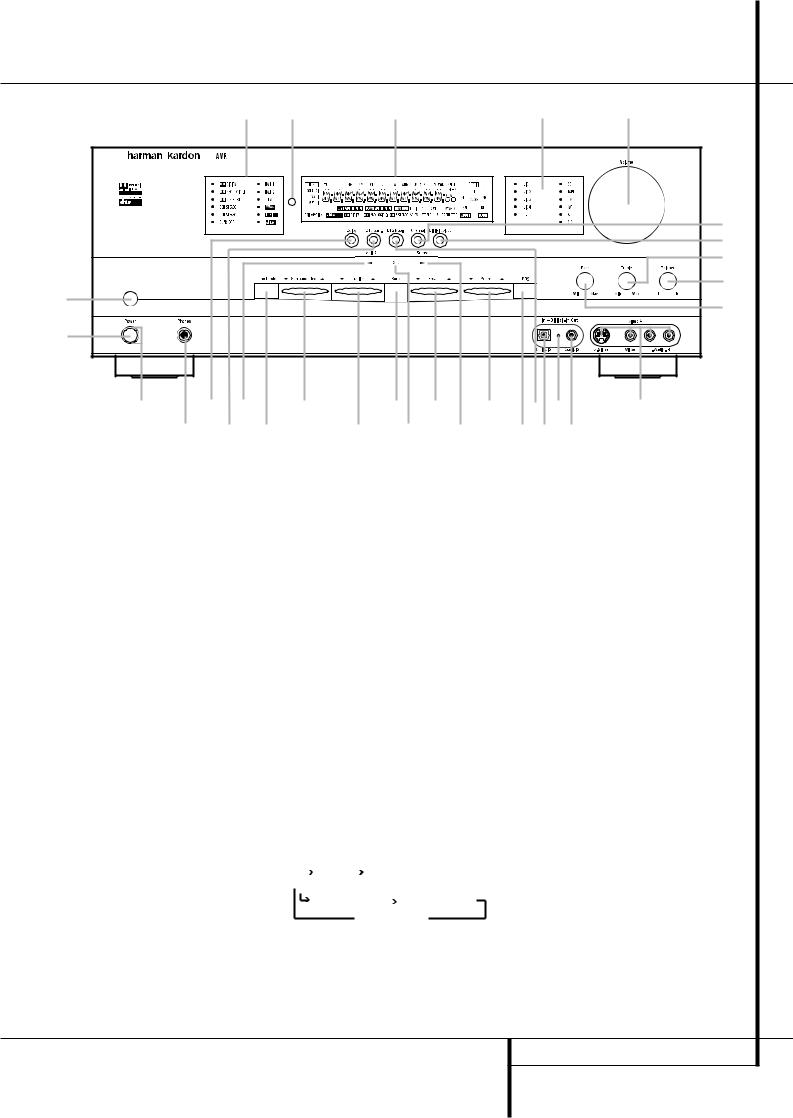
1Main Power Switch 2 System Power Control 3 Power Indicator
4 Headphone Jack
5 Dolby Mode Selector
6 DTS Surround Mode Selector
7 Logic 7 Mode Selector /‹ Button
8 Tone Mode
9 Surround Mode Selector )Tuning Selector
!Tuner Band Selector
1Main Power Switch: Press this button to apply power to the AVR 4500. When the switch is pressed in, the unit is placed in a Standby mode, as indicated by the orange LED 3surrounding the System Power Control 2. This button MUST be pressed in to operate the unit. To turn the unit off completely and prevent the use of the remote control, this switch should be pressed until it pops out from the front panel so that the word “OFF” may be read at the top of the switch.
NOTE: This switch is normally left in the “ON” position.
2System Power Control: When the Main Power Switch 1is “ON,” press this button to turn on the AVR 4500; press it again to turn the unit off (to Standby). Note that the Power Indicator surrounding the switch 3will turn green when the unit is on.
3Power Indicator: This LED will be illuminated in orange when the unit is in the Standby mode to signal that the unit is ready to be turned on. When the unit is in operation, the indicator will turn green.
@Set Button |
ÒBalance Control |
#Preset Station Selector |
ÚTreble Control |
$Stereo Mode Selector /› Button |
ÛDigital Select Button |
%Input Source Selector |
ÙChannel Select Button |
^RDS Selector |
ıVolume Control |
&DTS Neo:6 Mode Selector |
ˆInput Indicators |
*Digital Optical 3 Input |
˜Main Information Display |
(Input/Output Status indicator |
¯Remote Sensor Window |
ÓDigital Coax 3 Jack |
˘Surround Mode Indicators |
ÔVideo 4 Input Jacks |
|
Bass Control |
|
4Headphone Jack: This jack may be used to listen to the AVR 4500’s output through a pair of headphones. Be certain that the headphones have a standard 6.3 mm stereo phone plug. Note that the main room speakers and all Preamp Outputs will automatically be turned off when the headphone jack is in use.
5Dolby Mode Selector: Pressing this selector button cycles the AVR through the various Dolby surround modes. The first press of the button switches the surround mode to the last Dolby surround mode that was in use.
Each subsequent press selects the next mode in the following order:
|
|
DOLBY |
|
DOLBY PRO LOGIC II MOVIE |
|
||
|
|
DIGITAL |
|
|
|||
|
|
|
|
|
|
|
|
|
DOLBY PRO LOGIC II |
DOLBY PRO LOGIC II |
|||||
|
|||||||
|
MUSIC |
|
|
|
EMULATION |
||
DOLBY 3 STEREO
Note that DOLBY DIGITAL mode is available only with digital input selected and the other modes only when a Dolby Digital source is not playing.
6 DTS Surround Mode Selector: When a DTS source is in use the AVR 4500 will select the appropriate mode automatically and no other mode will be available. In that case, pressing that button will display the mode currently selected by the AVR´s decoder. Depending on the surround material played and the speaker setting, one of the following modes will be selected by the unit:
•DTS-ES 6.1 DISCRETE
•DTS-ES 6.1 MATRIX
•DTS + NEO:6
•DTS 5.1
Both DTS ES 6.1 Modes and DTS+NEO:6 will be selected only when surround back speakers have been configured with your system: DISCRETE with appropriate source material, MATRIX with 6.1 Matrix recordings and DTS+NEO:6 with normal DTS 5.1 channel recordings. The DTS 5.1 mode will be selected with any DTS source, when no surround back speakers are configured (see also pages 24 and 32-35).
FRONT PANEL CONTROLS 5

Front Panel Controls
7Logic 7 Mode Selector /‹ Button: This button has two functions: In normal use, press it to select one of the Logic 7 modes. When an adjustment is being made using the Channel Select Ùor Digital Select Ûbuttons, this button may be pressed to scroll through the available options.
8Tone Mode: Pressing this button enables or disables the Balance, Bass and Treble tone controls. When the button is pressed so that the words TONE IN appear in the Main Information Display ˜, the settings of the Bass
and Treble Úcontrols and of the Balance control Òwill affect the output signals. When the button is pressed so that the words TONE OUT appear in the Main Information Display ˜, the output signal will be “flat,” without any balance, bass or treble alteration, no matter how the actual Controls ÒÚare adjusted.
9 Surround Mode Selector: Press this button to select any of the HALL, THEATER or VMAx surround modes. Note that depending on the type of input, some modes are not always available. (See page 32 for more information about surround modes.)
)Tuning Selector: Press the left side of the button to tune lower frequency stations and the right side of the button to tune higher frequency stations. When a station with a strong signal is reached, the TUNED indicator Wwill illuminate in the Main Information Display ˜ (see page 40 for more information on tuning stations).
!Tuner Band Selector: Pressing this button will automatically switch the AVR 4500 to the Tuner mode. Pressing it again will switch between the AM and FM frequency bands. Holding it pressed for 3 seconds will switch between stereo or mono receiving and automatic or manual tuning mode. When the button is pressed so that the AUTO Indicator Xlights, the tuner will search for the next station with an acceptable signal when the Tuning Selector )Kéis pressed. When the button is pressed so that the AUTO Indicator Xis not lit, each press of the Tuning Selector )Kéwill increase the frequency. (See page 40 for more information on using the tuner.)
@Set Button: When making choices during the setup and configuration process, press this button to enter the desired setting as shown in the Main Information Display Ûinto the AVR 4500’s memory.
# Preset Stations Selector: Press this button to scroll up or down through the list of stations that have been entered into the preset memory. (See page 40 for more information on tuner programming.)
$ Stereo Mode Selector /› Button: This button has two functions: In normal use, pressing this selector button cycles through the stereo modes, and it is also used to turn off all surround processing and place the unit in a traditional two-channel Stereo mode. The first press selects 5-Channel Stereo or 7-Channel Stereo, depending on the selection (5.1 or 6.1/7.1) made in the surround mode setting, see page 23, and the second selects “SURROUND OFF,” which is true Stereo. When an adjustment is being made using the Channel Select Ùor Digital Select Û buttons, this button may be pressed to scroll through the available options.
%Input Source Selector: Press this button to change the input by scrolling through the list of input sources.
^RDS Select Button: Press this button to display the various messages that are part of the RDS data system of the AVR 4500’s tuner. (See page 30 for more information on RDS).
& DTS Neo:6 Mode Selector: Pressing this selector button cycles the AVR through the various DTS Neo:6 modes, which extract a fiveor seven-channel surround field from two-channel program material (from PCM source or analog input signal). The first press selects the last DTS Neo:6 surround mode that was in use, and each subsequent press selects the next mode in the following order:

 DTS Neo:6 MUSIC
DTS Neo:6
MOVIES
*Digital Optical 3 Input: Connect the optical digital audio output of an audio or video product to this jack. When the Input is not in use, be certain to keep the plastic cap installed to avoid dust contamination that might degrade future performance.
(Input/Output Status Indicator: This LED indicator will normally light green to show that the Coaxial 3 digital Ójack is operating as an input. When this jack has been configured for use as an output, the indicator will turn red to show that the jack may be used for recording. (See page 21 for more information on configuring the front panel jack as output, rather than input.)
ÓDigital Coax 3 Jack: This jack is normally used for connection to the output of portable audio devices, video game consoles or other products that have a coax digital jack. It may also be configured as an output jack, to feed a digital signal to a CD-R, MiniDisc or other digital recording device. (See page 21 for information on configuring the Digital Coax 3 Jack to an output.)
ÔVideo 4 Input Jacks: These audio/video jacks may be used for temporary connection to video games or portable audio/video products such as camcorders and portable audio players.
Bass Control: Turn this control to modify the low frequency output of the left/right channels by as much as ±10dB. Set this control to a suitable position for your taste or room acoustics.
Ò Balance Control: Turn this control to change the relative volume for the front left/right channels.
NOTE: For proper operation of the surround modes this control should be at the midpoint or “12 o’clock” position.
ÚTreble Control: Turn this control to modify the high frequency output of the left/right channels by as much as ±10dB. Set this control to a suitable position for your taste or room acoustics.
Û Digital Select Button: When playing a source that has a digital output, press this button to select between the Optical * and
Coaxial Ó Digital inputs (See page 33 for more information).
ÙChannel Select Button: Press this button to begin the process of trimming the channel output levels using an external audio source. (For more information on output level trim adjustment, see page 35).
ıVolume Control: Turn this knob clockwise to increase the volume, counterclockwise to decrease the volume. If the AVR is muted, adjusting volume control will automatically release the unit from the silenced condition.
ˆInput indicators: A green LED will light in front of the input that is currently being used as the source for the AVR 4500.
˜ Main Information Display: This display delivers messages and status indications to help you operate the receiver. (See pages 7–8 for a complete explanation of the Information Display.)
¯ Remote Sensor Window: The sensor behind this window receives infrared signals from the remote control. Aim the remote at this area and do not block or cover it unless an external remote sensor is installed.
˘ Surround Mode Indicators: A green LED will light in front of the surround mode that is currently in use.
6 FRONT PANEL CONTROLS
Front Panel Information Display
|
|
|
|
|
|
|
|
|
|
|
|
|
|
|
|
|
|
|
|
|
|
|
|
|
|
|
|
|
|
|
|
|
|
|
|
|
|
|
|
|
|
|
|
|
|
|
|
|
|
|
|
|
|
|
|
|
|
|
|
|
|
|
|
|
|
|
|
|
|
|
|
|
|
|
|
|
|
|
|
|
|
|
|
|
|
|
|
|
|
|
|
|
|
|
|
|
|
|
|
|
|
|
|
|
|
|
|
|
|
|
|
|
|
|
|
|
|
|
|
|
|
|
|
|
|
|
|
|
|
|
|
|
|
|
|
|
|
|
|
|
|
|
|
|
|
|
|
|
|
|
|
|
|
|
|
|
|
|
|
|
|
|
|
|
|
|
|
|
|
|
|
|
|
|
|
|
|
|
|
|
|
|
|
|
|
|
|
|
|
|
|
|
|
|
|
|
|
|
|
|
|
|
|
|
|
|
|
|
|
|
|
|
|
|
|
|
|
|
|
|
|
|
|
|
|
|
|
|
|
|
|
|
|
|
|
|
|
|
|
|
|
|
|
|
|
|
|
|
|
|
|
|
|
|
|
|
|
|
|
|
|
|
|
|
|
|
|
|
|
|
|
|
|
|
|
|
|
|
|
|
|
|
|
|
|
|
|
|
|
|
|
|
|
|
|
|
|
|
|
|
|
|
|
|
|
|
|
|
|
|
|
|
|
|
|
|
|
|
|
|
|
|
|
|
|
|
|
|
|
|
|
|
|
|
|
|
|
|
|
|
|
|
|
|
|
|
|
|
|
|
|
|
|
|
|
|
|
|
|
|
|
|
|
|
|
|
|
|
|
|
|
|
|
|
|
|
|
|
|
|
|
|
|
|
|
|
|
|
|
|
|
|
|
|
|
|
|
|
|
|
|
|
|
|
|
|
|
|
|
|
|
|
|
|
|
|
|
|
|
|
|
|
|
|
|
|
|
|
|
|
|
|
|
|
|
|
|
|
|
|
|
|
|
|
|
|
|
|
|
|
|
|
|
|
|
|
|
|
|
|
|
|
|
|
|
|
|
|
|
|
|
|
|
|
|
|
|
|
|
|
|
|
|
|
|
|
|
|
|
|
|
|
|
|
|
|
|
|
|
|
|
|
|
|
|
|
|
|
|
|
|
|
|
|
|
|
|
|
|
|
|
|
|
|
|
|
|
|
|
|
|
|
|
|
|
|
|
|
|
|
|
|
|
|
|
|
|
|
|
|
|
|
|
|
|
|
|
|
|
|
|
|
|
|
|
|
|
|
|
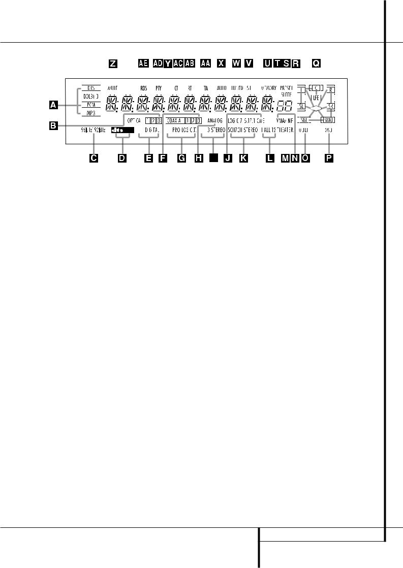
A Bitstream Indicators |
|
|
|
|
L Hall Mode Indicator |
|
|
W Tuned Indicator |
|||||||||||||||||||||||||||||
B Optical Source Indicators |
|
|
|
|
M Theater Mode Indicator |
|
|
X Auto Indicator |
|||||||||||||||||||||||||||||
C Sample Rate Indicators |
|
|
|
|
N VMAx Mode Indicator |
|
|
Y Main Information Display |
|||||||||||||||||||||||||||||
D DTS Mode Indicator |
|
|
|
|
O Multiroom Indicator |
|
|
Z Mute Indicator |
|||||||||||||||||||||||||||||
E Dolby Digital Indicator |
|
|
|
|
P OSD Indicator |
|
|
AATraffic Indicator |
|||||||||||||||||||||||||||||
F Coaxial Source Indicators |
|
|
|
|
Q Speaker/Channel Input Indicators |
|
|
ABRadiotext Indicator |
|||||||||||||||||||||||||||||
G Dolby Pro Logic II Indicator |
|
|
|
|
R Preset Number/Sleep Timer |
|
|
ACClock Time Indicator |
|||||||||||||||||||||||||||||
H Analog Input Indicator |
|
|
|
|
S Preset Indicator |
|
|
ADProgram Type Indicator |
|||||||||||||||||||||||||||||
I Dolby 3 Stereo Indicator |
|
|
|
|
T Sleep Indicator |
|
|
AERDS Indicator |
|||||||||||||||||||||||||||||
J Logic 7 Mode Indicators |
|
|
|
|
U Memory Indicator |
|
|
|
|
|
|
|
|
|
|
|
|
|
|
|
|
|
|||||||||||||||
K 5 Channel/7 Channel Stereo Indicators |
|
|
|
|
V Stereo Indicator |
|
|
|
|
|
|
|
|
|
|
|
|
|
|
|
|
|
|||||||||||||||
ABitstream™ Indicators: When the input is a digital source, one of these indicators will light to display the specific type of signal in use.
BOptical Source Indicators: These indicators light to show when a Optical Digital Input has been selected.
CSample Rate Indicators: One of these indicators will light when 96kHz or 192kHz source material is in use.
DDTS Mode Indicator: This indicator illuminates when the DTS mode is selected
EDolby Digital Indicator: This indicator illuminates when the Dolby Digital mode is selected.
FCoaxial Source Indicators: These indicators light to show when a Coaxial Digital Input has been selected.
GDolby Pro Logic II Indicator: This indicator lights when any Dolby Pro Logic II mode has been selected.
NOTE: It is possible to see the Dolby Pro Logic II indicator lit simultaneously with the Dolby Digital indicator, even though the Dolby Digital surround mode has been selected. This is due to the specifications for Dolby Digital processing, which require that the Dolby Pro Logic II mode be applied when a 2-channel Dolby Digital signal (2.0 recording) with Pro Logic information (Pro Logic flag on) is detected. For more information
see page 34. If you desire 5.1-channel audio, check the audio settings in the menus for your DVD disc to make sure that a 5.1-channel Dolby Digital soundtrack has been selected.
HAnalog Input Indicator: This indicator lights when an analog input source has been selected.
IDolby 3 Stereo Indicator: This indicator lights when the Dolby 3 Stereo Mode has been selected.
JLogic 7 Mode Indicators: These indicators light to indicate that one of the Logic 7 modes is in use. Along with the main Logic 7 indicator, either 5.1 or 7.1 will light to indicate the selected speaker configuration. One of the three letters to the far right of this segment will light to show which version of Logic 7 processing is in use: C for the Cinema mode, M for the Music mode and E for the Enhanced mode used with two-channel sources. (See page 29 for a description of the Logic 7 modes.)
K5-Channel/7-Channel Stereo Indicators:
These indicators light to show if the 5-Channel or 7-Channel Stereo mode has been selected. Only the indicator STEREO will light when "Surround Off" has been selected. Then all Surround Modes are turned off and the unit will play in pure stereo mode.
LHall Mode Indicators: These indicators light when one of the Hall modes has been selected.
MTheater Mode Indicator: This indicator illuminates to show that the Theater mode is in use.
NVMAx Mode Indicators: One of these indicators lights when the VMAx mode is in use. VMAx F appears when the Far Field VMAx mode is selected; VMAx N appears when the Near Field VMAx mode is selected. (See page 29 for a description of the VMAx modes.)
OMultiroom Indicator: This indicator lights when the multiroom system is active. Note that it will remain lit when the multiroom system is in use even though the main room system is in the Standby mode and all other indicators are dark. (See page 39 for more information on the Multiroom system.)
POSD Indicator: When the OSD system is in use, this indicator lights to remind you that the other indicators in this display do not function when the On Screen Display is being used.
FRONT PANEL INFORMATION DISPLAY 7

Front Panel Information Display
Q Speaker/Channel Input Indicators: These indicators are multipurpose, indicating either the speaker type selected for each channel or the incoming data-signal configuration. The left, center, right, right surround, left surround, right back surround and left back surround speaker indicators are composed of three boxes, while the subwoofer is a single box. The center box lights when a “Small” speaker is selected, and the two outer boxes light when “Large” speakers are selected. When none of the boxes are lit for the center, surround or subwoofer channels, no speaker has been selected for that position. (See page 21 for more information on configuring speakers.) The letters inside each of the center boxes display active input channels. For standard analog inputs, only the L and R will light, indicating a stereo input. When a digital source is playing, the indicators will light to display the channels begin received at the digital input. When the letters flash, the digital input has been interrupted. (See pages 23 and 34 for more information on the Channel Indicators).
R Preset Number/Sleep Timer: When the tuner is in use, these numbers indicate the specific preset memory location in use. (See page 40 for more information on preset stations.) When the Sleep function is in use, these numbers show how many minutes remain before the unit goes into the Standby mode.
S Preset Indicator: This indicator lights when the tuner is in use to show that the Preset Number/Sleep Timer Ris showing the station’s preset memory number. (See page 40 for more information on tuner presets.)
TSleep Indicator: This indicator lights when the Sleep function is in use. The numbers in the
Preset Number/Sleep Timer Rindicators will show the minutes remaining before the AVR 4500 goes into the Standby mode.
(See page 31 for more information on the Sleep function.)
UMemory Indicator: This indicator flashes when entering presets and other information into the tuner’s memory.
VStereo Indicator: This indicator illuminates when an FM station is being tuned in stereo.
WTuned Indicator: This indicator illuminates when a station is being received with sufficient signal strength to provide acceptable listening quality.
XAuto Indicator: This indicator illuminates when the tuner’s Auto mode is in use.
YMain Information Display: This display shows messages relating to the status, input source, surround mode, tuner, volume level or other aspects of the AVR 4500’s operation.
ZMute Indicator: This indicator illuminates to remind you that the AVR 4500’s output has been silenced by pressing the Mute button ˚ . Press the Mute button again to return to the previously selected output level.
AATA Traffic Announcement Indicator:
This indicator illuminates if the RDS station tuned somtimes transmits traffic information (see page 41 for more information on RDS).
ABRT Text Indicator: This indicator illuminates when the RDS station tuned is transmitting radiotext (RT) data.
ACClock Time Indicator: This indicator illuminates when the RDS station tuned is transmitting the CT (clock time) code, indicating the current time of day.
ADPTY Indicator: This indicator illuminates when the RDS station tuned is transmitting program type data, or during a PTY search.
AERDS Indicator: This indicator illuminates when the station tuned is transmitting RDS data.
8 FRONT PANEL INFORMATION DISPLAY
Rear Panel Connections
! # |
% |
|
|
|
|
|
" |
$ & |
|
|
|
|
|
|
|
|
|
|
|
230 V/50Hz |
|
|
|
|
|
|
|
|
|
|
|
|
|
AC OUTLETS |
|
|
|
|
|
|
~230V/50Hz |
|
|
|
|
|
UNSWITCHED / 100W MAX |
|
|
|
|
|
|
|
|
|
|
|
|
|
|
SWITCHED / 50W MAX |
|
|
|
|
|
|
|
|
|
|
|
|
|
|
|
|
|
|
|
|
|
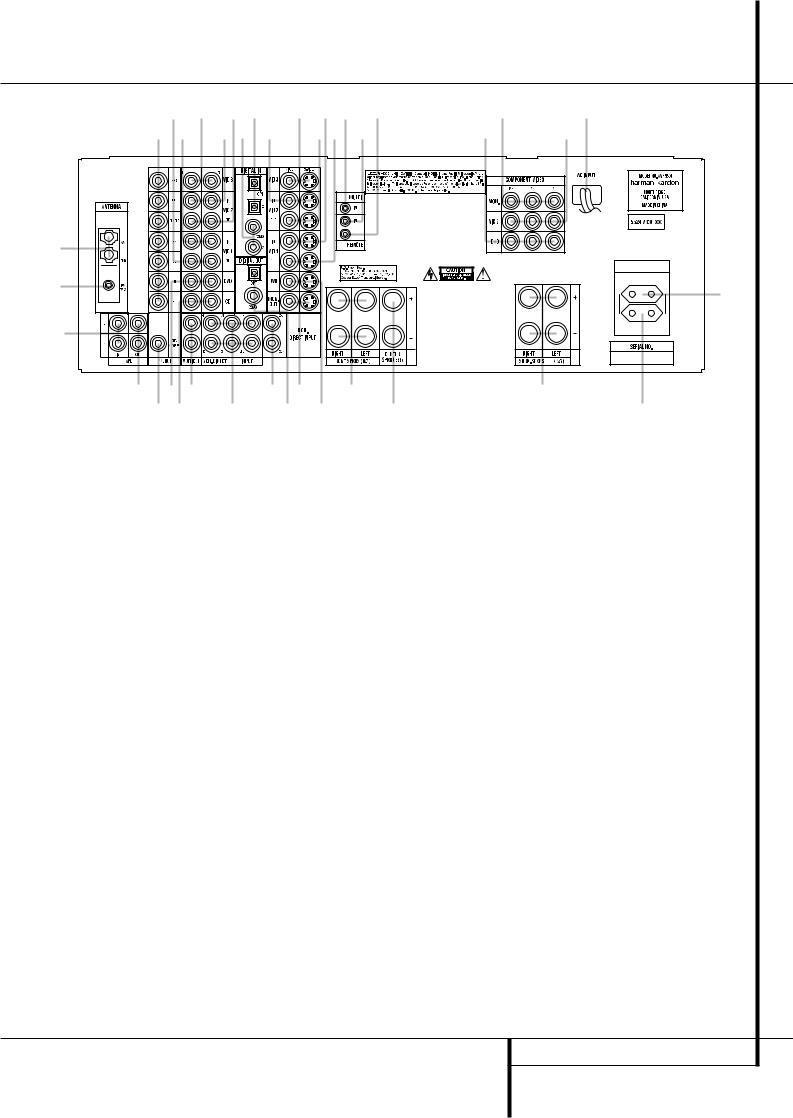
AM Antenna
FM Antenna
Tape Inputs Tape Outputs
Subwoofer Output
DVD Audio Inputs
CD Inputs
Multiroom Outputs
6-Channel Direct Inputs
8-Channel Direct Inputs
Digital Audio Outputs
Video Monitor Outputs
DVD Video Inputs
Front Speaker Outputs
NOTE: To assist in making the correct connections for multichannel input/output and speaker connections, all connection jacks and terminals have been color coded in conformance with the latest CEA standards as follows:
Front Left: |
White |
Front Right: |
Red |
Center: |
Green |
Surround Left: |
Blue |
Surround Right: |
Gray |
Surround Back Left: |
Brown |
Surround Back Right: |
Tan |
Subwoofer (LFE): |
Purple |
Digital Audio: |
Orange |
Composite Video: |
Yellow |
Component Video “Y”: |
Green |
Component Video “Pr”: |
Red |
Component Video “Pb”: |
Blue |
AM Antenna: Connect the AM loop antenna supplied with the receiver to these terminals. If an external AM antenna is used, make connections to the AM and GND terminals in accordance with the instructions supplied with the antenna.
Center Speaker Outputs |
Video 3 Video Inputs |
Surround Speaker Outputs |
& Video 2 Video Inputs |
Switched AC Accessory Outlet |
% Optical Digital Inputs |
Unswitched AC Accessory Outlet |
$ Coaxial Digital Inputs |
AC Power Cord |
Video 2 Audio Outputs |
Video 2 Component Video Inputs |
Video 2 Audio Inputs |
Component Video Outputs |
# Video 3 Audio Inputs |
DVD Component Video Inputs |
" Video 1 Audio Inputs |
Remote IR Output |
! Video 1 Audio Outputs |
Remote IR Input |
Preamp Outputs |
Multiroom IR Input |
|
Video 1 Video Outputs |
|
Video 1 Video Inputs |
|
Video 2 Video Outputs |
|
FM Antenna: Connect the supplied indoor or an optional external FM antenna to this terminal.
Tape Inputs: Connect these jacks to the PLAY/OUT jacks of an audio recorder.
Tape Outputs: Connect these jacks to the RECORD/INPUT jacks of an audio recorder.
Subwoofer Output: Connect this jack to the line-level input of a powered subwoofer. If an external subwoofer amplifier is used, connect this jack to the subwoofer amplifier input.
DVD Audio Inputs: Connect these jacks to the analog audio jacks on a DVD or other audio or video source.
CD Inputs: Connect these jacks to the analog output of a compact disc player or CD changer or any other audio source.
Multiroom Outputs: Connect these jacks to an optional audio power amplifier to listen to the source selected by the multiroom system in a remote room.
6-Channel Direct Inputs: If an external digital audio decoder is used, connect the outputs of that decoder to these jacks.
8-Channel Direct Inputs: When an optional, external processor or playback device with 6.1 or 7. 1 audio capability is in use, connect the Surround Back Left and Surround Back Right channel outputs of the player to these input jacks and all other 6.1/7.1 outputs to the appropriate
6-Channel Direct Inputs .
Digital Audio Outputs: Connect these jacks to the matching digital input connector on a digital recorder such as a CD-R or MiniDisc recorder.
Video Monitor Outputs: Connect this jack to the composite and/or S-Video input of a TV monitor or video projector to view the on-screen menus and the output of any standard Video or S-Video source selected by the receiver’s video switcher.
REAR PANEL CONNECTIONS 9

Rear Panel Connections
DVD Video Inputs: Connect these jacks to the composite or S-Video output jacks on a DVD player or other video source.
Front Speaker Outputs: Connect these outputs to the matching + or – terminals on your left and right speakers. In conformance with the new CEA color code specification, the White terminal is the positive, or "+" terminal that should be connected to the red (+) terminal on Front Left speaker with the older color coding, while the Red terminal is the positive, or "+" terminal that should be connected to the red (+) terminal on Front Right speaker. Connect the black (–) terminals on the AVR 4500 to the black
(–) terminals on the speakers. See page 15 for more information on speaker polarity.
Center Speaker Outputs: Connect these outputs to the matching + and – terminals on your center channel speaker. In conformance with the new CEA color code specification, the Green Terminal is the positive, or "+" terminal that should be connected to the red (+) terminal on speakers with the older color coding. Connect the black (–) terminal on the AVR to the black negative (–) terminal on your speaker. (See page 15 for more information on speaker polarity.)
Surround Speaker Outputs: Connect these outputs to the matching + and – terminals on your surround channel speakers. In conformance with the new CEA color code specification, the Blue terminal is the positive, or "+" terminal that should be connected to the red (+) terminal on the Surround Left speaker with older color coding, while the Gray terminal should be connected to the red (+) terminal on the Surround Right speaker with the older color coding. Connect the black (–) terminal on the AVR to the matching black negative (–) terminals for each surround speaker. (See page 15 for more information on speaker polarity.)
Switched AC Accessory Outlet: This outlet may be used to power any device that you wish to have turn on when the AVR 4500 is turned on with the System Power Control switch 2.
Unswitched AC Accessory Outlet: This outlet may be used to power any AC device. The power will remain on at this outlet regardless of whether the AVR 4500 is on or off (in Standby), provided that the Main Power switch 1is on.
Note: The total power consumption of all devices connected to the accessory outlets should not exceed 100 watts from the
Unswitched Outlet and 50 W from the Switched Outlet .
AC Power Cord: Connect the AC plug to an unswitched AC wall output.
Video 2 Component Video Inputs:
Connect the Y/Pr/Pb component video outputs of an HDTV Set-top convertor, satellite receiver, or other video source device with component video outputs to these jacks.
Monitor Component Video Outputs:
Connect these outputs to the component video inputs of a video projector or monitor. When a source connected to one of the two
Component Video Inputs is selected the signal will be sent to these jacks.
DVD Component Video Inputs: Connect the Y/Pr/Pb component video outputs of a DVD player to these jacks.
Note: All component inputs/outputs can be used for RGB signals too, in the same way as described for the Y/Pr/Pb signals, then connected to the jacks with the corresponding color.
RGB connection is not possible if the source outputs a separate sync signal (see page 16).
Remote IR Output: This connection permits the IR sensor in the receiver to serve other remote controlled devices. Connect this jack to the “IR IN” jack on Harman Kardon or other compatible equipment.
Remote IR Input: If the AVR 4500’s frontpanel IR sensor is blocked due to cabinet doors or other obstructions, an external IR sensor may be used. Connect the output of the sensor to this jack.
Multiroom IR Input: Connect the output of an IR sensor in a remote room to this jack to operate the AVR 4500’s multiroom control system.
Video 1 Video Outputs: Connect these jacks to the RECORD/INPUT composite or S-Video jack on a VCR.
Video 1 Video Inputs: Connect these jacks to the PLAY/OUT composite or S-Video jacks on a VCR or other video source.
Video 2 Video Outputs: Connect these jacks to the RECORD/INPUT composite or S-Video jacks on a second VCR.
Video 3 Video Inputs: Connect these jacks to the PLAY/OUT composite or S-Video jacks on any video source.
&Video 2 Video Inputs: Connect these jacks to the PLAY/OUT composite or S-Video jacks on a second VCR or other video source.
% Optical Digital Inputs: Connect the optical digital output from a DVD player, HDTV receiver, the S/PDIF output of a compatible computer sound card playing MP3 files or streams, LD player, MD player or CD player to these jacks. The signal may be either a Dolby Digital signal, a DTS signal, a 2 channel MPEG 1 signal, an MP3 data stream or a standard PCM digital source.
$ Coaxial Digital Inputs: Connect the coax digital output from a DVD player, HDTV receiver, the S/PDIF output of a compatible computer sound card playing MP3 files or streams, LD player, MD player or CD player to these jacks. The signal may be either a Dolby Digital signal, DTS signal, a 2 channel MPEG 1 signal, an MP3 data stream or a standard PCM digital source. Do not connect the RF digital output of an LD player to these jacks.
Video 2 Audio Outputs: Connect these jacks to the RECORD/INPUT audio jacks on a VCR or any Audio recorder.
Video 2 Audio Inputs: Connect these jacks to the PLAY/OUT audio jacks on a second VCR or other audio or video source.
#Video 3 Audio Inputs: Connect these jacks to the PLAY/OUT audio jacks on any audio or video source.
"Video 1 Audio Inputs: Connect these jacks to the PLAY/OUT audio jacks on a VCR or other audio or video source.
! Video 1 Audio Outputs: Connect these jacks to the RECORD/INPUT audio jacks on a VCR or any other Audio recorder.
Preamp Outputs: These jacks may be connected to an external power amplifier.
Note: Either the Video or S-Video output of any S-Video source must be connected to the
AVR 4500, not both in parallel, otherwise the video may be disturbed or its performance be adversely effected.
10 REAR PANEL CONNECTIONS

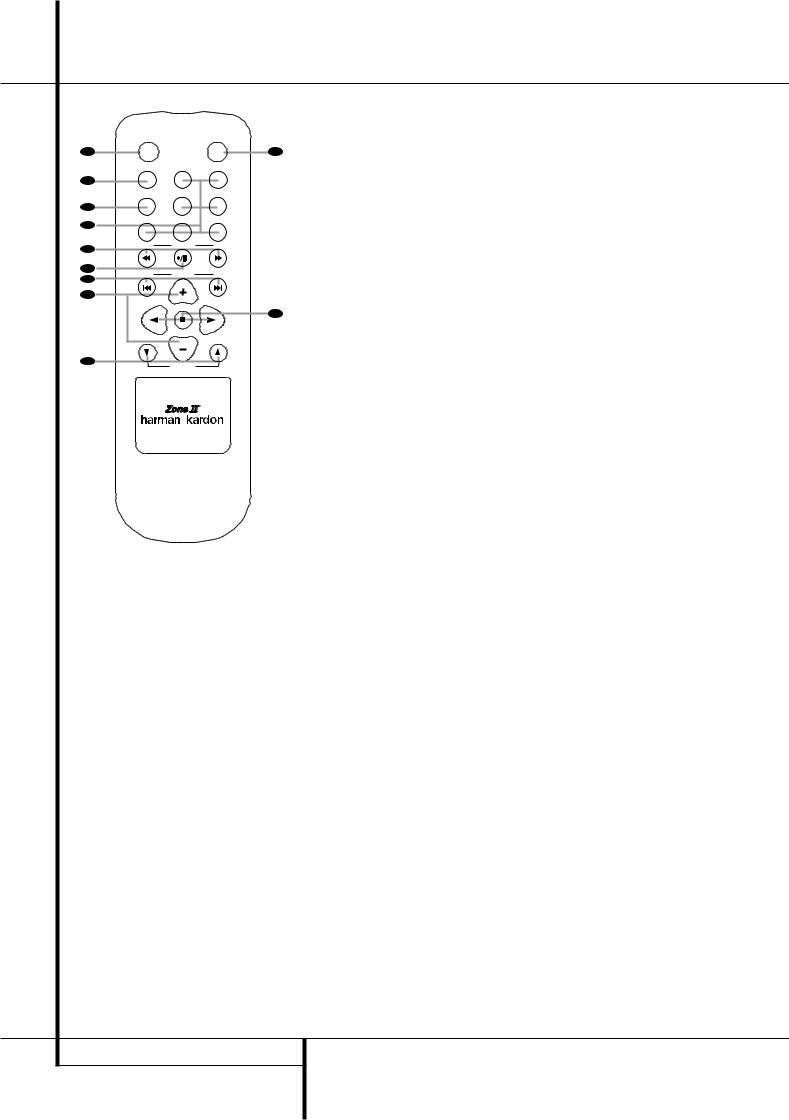
Main Remote Control Functions
0Power On Button
1IR Transmitter Window
2Program/SPL Indicator
3Power Off Button
4Input Selectors
5AVR Selector
6AM/FM Tuner Select
76-Channel/8-Channel Direct Input
8Test Button
9Sleep Button
ASurround Mode Selector
BNight Mode
CChannel Select Button
D⁄/¤ Buttons
E‹ Button
FSet Button
GDigital Select
HNumeric Keys
ITuner Mode
JDirect Button
KTuning Up/Down
LOSD Button
MDolby Mode Select Button
NDTS Digital Mode Selector
OLogic 7 Mode Select Button
PTransport Controls
QSkip Up/Down Buttons
Stereo Mode Select Button
DTS Neo:6 Mode Select
Macro Buttons
RDS Selector Button
!Preset Up/Down
"Clear Button
#Memory Button
$Delay/Prev. Ch.
%› Button
&Speaker Select
'Multiroom
(Volume Up/Down
)SPL Indicator Select
*Learn Button
Mute
+EzSet Sensor Microphone
NOTE: The function names shown here are each button’s feature when used with the AVR 4500. Most buttons have additional functions when used with other devices. See page 48-49 for a list of these functions.
MAIN REMOTE CONTROL FUNCTIONS 11
Main Remote Control Functions
IMPORTANT NOTE: The AVR4500’s remote may be programmed to control up to seven devices, including the AVR 4500. Before using the remote, it is important to remember to press the Input Selector button 4that corresponds to the unit you wish to operate. In addition, the AVR 4500’s remote is shipped from the factory to operate the AVR 4500 and most Harman Kardon CD or DVD players and cassette decks. The remote is also capable of operating a wide variety of other products using the control codes that are part of the remote or by learning commands from other remotes. Before using the remote with other products, follow the instructions on pages 42-45 to program the proper codes for the products in your system.
It is also important to remember that many of the buttons on the remote take on different functions, depending on the product selected using the
Input Selector Button 4. The descriptions shown here primarily detail the functions of the remote when it is used to operate the AVR 4500. (See page 45 for information about alternate functions for the remote’s buttons.)
0Power Off Button: Press this button to place the AVR 4500 or a selected device unit in the Standby mode. Note that when the AVR 4500 is switched off this will turn off the main room functions, but if the Multiroom system is activated, it will continue to function.
1IR Transmitter Window: Point this window towards the AVR 4500 when pressing buttons on the remote to make certain that infrared commands are properly received.
2Program/SPL Indicator: This three-color indicator is used to guide you through the process of programming the remote or learning commands from a remote into the AVR 4500’s remote code memory and it is also used as a level indicator when using the remote’s EzSet capabilities. (See page 26 for more information on setting output levels, and see page 42 for information on programming the remote.)
3Power On Button: Press this button to turn on the power to a device selected by pressing one of the Input Selectors 4(except Tape).
4Input Selectors: Pressing one of these buttons will perform three actions at the same time. First, if the AVR is not turned on, this will power up the unit. Next, it will select the source shown on the button as the input to the AVR. Finally, it will change the remote control so that it controls the device selected. After pressing one of these buttons you must press the
AVR Selector button 5again to operate the AVR’s functions with the remote.
5AVR Selector: Pressing this button will switch the remote so that it will operate the AVR’s functions. If the AVR is in the Standby mode, it will also turn the AVR on.
6AM/FM Tuner Select: Press this button to select the AVR’s tuner as the listening choice. Pressing this button when the tuner is in use will select between the AM and FM bands.
76-Channel/8 Channel Direct Input: Press this button to select the device connected to the
6-Channel Direct Inputs or the
8-Channel Direct Inputs (the input available will depend on the selection 5.1 or 6.1/7.1 made in the surround mode setting, see page 23 for more information).
8Test Tone: Press this button to begin the sequence used to calibrate the AVR 4500’s output levels. (See page 26 for more information on calibrating the AVR 4500.)
9Sleep Button: Press this button to place the unit in the Sleep mode. After the time shown in the display, the AVR 4500 will automatically go into the Standby mode. Each press of the button changes the time until turn-off in the following order:
|
|
90 |
|
80 |
|
|
|
70 |
|
|
|
60 |
|
50 |
|
|
|
|
min |
|
min |
|
|
min |
|
|
min |
|
|
min |
|
||
|
|
|
|
|
|
|
|
|
|
|
|
|
|
|
|
|
|
40 |
|
30 |
|
|
20 |
|
|
10 |
|
|
OFF |
||||
|
|
|
|
|
|
|
|
|||||||||
|
|
min |
|
min |
|
|
min |
|
|
min |
|
|
||||
|
|
|
|
|
|
|
|
|
|
|
||||||
Hold the button pressed for two seconds to turn off the Sleep mode setting.
Note that this button is also used to change channels on your TV, VCR and Sat receiver when the appropriate source is selected, using the device Input Selectors 4.
ASurround Mode Selector: Press this button to select any of the HALL, THEATER or VMAx surround modes. Note that depending on the type of input, some modes are not always available. (See page 29 for more information about surround modes.) Note that this button is also used to tune channels on your TV, VCR and Sat receiver when the appropriate source is selected using the device Input Selector 4.
BNight Mode: Press this button to activate the Night mode. This mode is available only with Dolby Digital encoded sources, and it preserves dialog (center channel) intelligibilty at low volume levels (See page 25 for more information).
CChannel Select Button: This button is used to start the process of setting the AVR 4500’s output levels with an external source. Once this button is pressed, use the ⁄/¤ buttons Dto select the channel being adjusted, then press the Set button F, followed by the ⁄/¤ buttons Dagain, to change the level setting. (See page 35 for more information.)
D⁄/¤ Buttons:These multipurpose buttons are used to change or scroll through items in the on-screen menus or on the front panel or to make configuration settings such as digital inputs or delay timing. When changing a setting, first press the button for the function or setting to be changed (e.g., press the Digital Select Button Gto change a digital input) and then press one of these buttons to scroll through the list of options or to increase or decrease a setting. The sections in this manual describing the individual features and functions contain specific information on using these buttons for each application.
When the AVR 4500 remote is being programmed for the codes of another device, these buttons are also used in the “Auto Search” process (See page 42 for more information on programming the remote.)
E‹ Button: This button is used to change the menu selection or setting during some of the setup procedures for the AVR 4500.
FSet Button: This button is used to enter settings into the AVR 4500’s memory. It is also used in the setup procedures for delay time, speaker configuration and channel output level adjustment.
GDigital Select: Press this button to assign one of the digital inputs %$*Óto a source. (See page 33 for more information on using digital inputs.)
HNumeric Keys: These buttons serve as a ten-button numeric keypad to enter tuner preset positions. They are also used to select channel numbers when TV, VCR or Sat receiver has been selected on the remote, or to select track numbers on a CD, DVD or LD player, depending on how the remote has been programmed.
ITuner Mode: Press this button when the tuner is in use to select between automatic tuning and manual tuning. When the button is pressed so that the AUTO indicator Xgoes out, pressing the Tuning buttons K)≠will move the frequency up or down in single-step increments. When the FM band is in use and the AUTO indicator Xis on, pressing this button will change to monaural reception making even weak stations audible or improving the audio performance with noisy stereo stations. (See page 40 for more information.)
JDirect Button: Press this button when the tuner is in use to start the sequence for direct entry of a station’s frequency. After pressing the button simply press the proper Numeric Keys Hto select a station (See page 40 for more information on the tuner).
12 MAIN REMOTE CONTROL FUNCTIONS

Main Remote Control Functions
KTuning Up/Down: When the tuner is in use, these buttons will tune up or down through the selected frequency band. If the Tuner Mode button Ihas been pressed or the Band button @on the front panel was held pressed so that the AUTO indicator Xis illuminated, pressing either of the buttons will cause the tuner to seek the next station with acceptable signal strength for quality reception. When the AUTO indicator Xis NOT illuminated, pressing these buttons will tune stations in single-step increments. (See page 40 for more information.)
LOSD Button: Press this button to activate the On Screen Display (OSD) system used to set up or adjust the AVR 4500’s parameters.
MDolby Mode Selector: This button is used to select one of the available Dolby Surround processing modes. Each press of this button will select one of the Dolby Pro Logic II modes, Dolby 3 Stereo or Dolby Digital. Note that the Dolby Digital mode is only available with a digital input selected and the other modes only as long as a Dolby Digital source is not playing (except Pro Logic II with Dolby Digital 2.0 recordings, see Note on page 7). See page 29 for the available Dolby surround mode options.
NDTS Digital Mode Selector: When a DTS source is in use the AVR 4500 will select the appropriate mode automatically and no other mode will be available. Pressing this button will display the mode currently selected by the AVR´s decoder, depending on the surround material played and the speaker setting (see item 6, page 5). When a DTS source is not in use, this button has no function. (See page 24, 29 for the available DTS options.)
OLogic 7 Selector: Press this button to select one of the available Logic 7 surround modes. (See page 29 for the available Logic 7 options.)
PTransport Control Buttons: These buttons do not have any functions for the AVR 4500, but they may be programmed for the forward/reverse play operation of a wide variety of CD or DVD players, and audio or videocassette recorders. (See page 42 for more information on programming the remote.)
QSkip Up/Down Buttons: These buttons do not have a direct function with the AVR 4500, but when used with a compatibly programmed CD or DVD player/changer they will change the tracks on the disc currently being played.
Stereo Mode Select Button: Pressing this selector button cycles through the stereo modes, and it is also used to turn off all surround processing and place the unit in a traditional twochannel Stereo mode. The first press selects 5- Channel Stereo or 7-Channel Stereo, depending on the selection (5.1 or 6.1/7.1) made in the surround mode setting, see page 23, and the second selects “SURROUND OFF,” which is true Stereo.
DTS Neo:6 Mode Selector: Pressing this selector button cycles the AVR through the various DTS Neo:6 modes, which extract a fiveor seven-channel surround field from two-channel program material (from PCM source or analog input signal). The first press selects the last DTS Neo:6 surround mode that was in use, and each subsequent press selects the next mode in the following order:

 DTS Neo:6 MUSIC
DTS Neo:6
MOVIES
Macro Buttons: Press these buttons to store or recall a “Macro”, which is a pre-pro- grammed sequence of commands stored in the remote. (See page 44 for more information on storing and recalling macros.)
RDS Select Button: Press this button to display the various messages that are part of the RDS data system of the AVR 4500’s tuner. (See page 41 for more information on RDS).
!Preset Up/Down: When the tuner is in use, press these buttons to scroll through the stations programmed into the AVR 4500’s memory. When CD or DVD is selected using the Input Selector button 4, these buttons may function as Slow Fwd/Rev (DVD) or ”+10” (CD, CDR).
"Clear Button: Press this button to clear incorrect entries when using the remote to
directly enter a radio station’s frequency.
#Memory Button: Press this button to enter a radio station into the AVR 4500’s preset memory. After pressing the button the MEMORY indicator Uwill flash; you then have five seconds to enter a preset memory location using the Numeric Keys H. (See page 40 for more information.)
$Delay/Prev Ch.: Press this button to begin the process for setting the delay times used by the AVR 4500 when processing surround sound. After pressing this button, the delay times are entered by pressing the Set button Fand then using the ⁄/¤ buttons Dto change the setting. Press the Set button again to complete the process. (See page 25 for more information.)
%› Button: Press this button to change a setting or selection when configuring many of the AVR’s settings.
&Speaker Select: Press this button to begin the process of configuring the AVR 4500’s Bass Management System for use with the type of speakers used in your system. Once the button has been pressed, use the ⁄/¤ buttons Dto select the channel you wish to set up.
Press the Set Button Fand then select the speaker type (Large, Small or None) appropriate with the speaker in use. (See page 21 for more information.)
'Multi-Room: Press this button to activate the Multiroom system or to begin the process of changing the input or volume level for the second zone. (See page 39 for more information on the Multiroom system.)
(Volume Up/Down: Press these buttons to raise or lower the system volume.
)SPL Indicator Select: This button activates the AVR 4500’s EzSet function to quickly and accurately calibrate the AVR 4500’s output levels. During this sequence, EzSet will automatically adjust the output levels for all channels until they are equal, as shown by the Program Indicator 2lighting green for each channel. (See page 26 for more information on EzSet.)
*Learn Button: Press this button to begin the process of “learning” the codes from another product’s remote into the AVR 4500’s remote. (See page 43 for more information on using the remote’s learning function.)
Mute: Press this button to momentarily silence the AVR 4500 or TV set being controlled, depending on which device has been selected. When the AVR 4500 remote is being programmed to operate another device, this button is pressed with the Input Selector button 4to begin the programming process. (See page 42 for more information on programming the remote.)
+EzSet Sensor Microphone: The sensor microphone for the EzSet microphone is behind these slots. When using the remote to calibrate speaker output levels using EzSet, be sure that you do not hold the remote in a way that covers these slots. (See page 26 for more information on using EzSet).
NOTE: With the press of any remote button the
Input Selector button 45associated with the botton pressed will briefly flash red to confirm the transmission of the command, as long as there is a function for that button with the device selected (see function list on pages 48, 49).
MAIN REMOTE CONTROL FUNCTIONS 13
Zone II Remote Control Functions
POWER MUTE
AOFF
AVR VID1 VID2
B |
|
|
|
|
|
AM/FM |
VID3 |
VID4 |
|
C |
|
|
|
|
D |
DVD |
CD |
TAPE |
|
|
|
|
||
E |
DN |
TUNING |
UP |
|
|
|
|
||
F |
DN |
PRESET |
UP |
|
G |
||||
|
|
|
||
H |
|
|
|
|
|
|
DISC SKIP |
|
|
|
|
DISC SKIP |
|
|
I |
|
VOLUME |
|
|
|
|
|
å Power Off
∫ AVR Selector
ç AM/FM Tuner Select
∂ Input Selectors
≠ Tuning Up/Down – Fast Play
ƒ Record/Pause
© Preset/Track Skip
˙ Disc Skip
î Volume Up/Down
∆ Play Forward/Reverse/Stop
˚ Mute
The Zone II remote may be used in either the same room where the AVR 4500 is located, or it may be used in a separate room with an option-
Kal infrared sensor that is connected to the AVR 4500’s Multi IR input jack .
åPower Off: When used in the room where the AVR 4500 is located, press this button to place the unit in Standby. When it is used in a remote room with a sensor that is connected to the Multi IR jack , this button turns the Multi-Room system off.
J∫AVR Selector: Press this button to turn on the AVR. The input in use when the unit was last on will be selected.
çAM/FM Tuner Select: Press this button to select the Tuner as the input to the Multiroom system. Press it again to change between the AM and FM bands.
∂Input Selectors: When the AVR is off, press one of these buttons to turn the unit on and to select a specific input. When the unit is already in use, pressing one of these buttons will change the input.
≠Tuning Up/Down – Fast Play: These buttons may be used to change the frequency of the tuner. These buttons may also control the Fast Play or Fast Reverse functions of compatible Harman Kardon CD, DVD or cassette decks in the same room, or from a remote room when an IR link is connected to the AVR 4500.
ƒRecord/Pause: Press this button to activate the Record or Pause function on compatible Harman Kardon CD, DVD or Cassette Deck products.
NOTE: The Zone II remote may be used in either the same room where the AVR 4500 is located, or it may be used in a separate room with an optional infrared sensor that is connected to the AVR 4500’s Multi IR input jack b. When it is used in the same room as the AVR 4500, it will control the functions of the AVR 4500 or any compatible Harman Kardon products in that room. When it is used in a separate room via a sensor connected to the Multi IR Jack b, the buttons for power, input source, volume and
©Preset Up/Down – Track Skip: When the AVR’s tuner is selected as the input source, these buttons will move up or down through the list of stations that have been stored in the preset memory. When a CD or DVD player is selected, these buttons activate the forward or reverse track or chapter skip functions.
˙Disc Skip: Press this button to change discs on compatible Harman Kardon CD or DVD changers.
îVolume Up/Down: When used in the room where the AVR 4500 is located, press this button to raise or lower the volume in that room. When it is used in a remote room with a sensor that is connected to the Multi IR Jack, this button will raise or lower the volume in the remote room.
∆Play Forward/Reverse/Stop: Press these buttons to control compatible Harman Kardon CD, DVD or cassette players.
˚Mute: When used in the room where the AVR 4500 is located, press this button to temporarily silence the unit. When it is used in a remote room with a sensor that is connected to the Multi IR Jack , this button will temporarily silence the feed to the remote room only. Press the button again to return to the previous volume level.
Important Note: No matter in which room the Zone II remote is used, as with the main remote it is important to remember to press the Input Selector button ∂that corresponds to the unit you wish to operate befor you change the device to be controlled.
mute will control the source and volume for the second zone, as connected to the Multi Out Jacks ‚. (See page 39 for complete information on using the Multiroom system.)
14 ZONE II REMOTE CONTROL FUNCTIONS

Installation and Connections
After unpacking the unit, and placing it on a solid surface capable of supporting its weight, you will need to make the connections to your audio and video equipment.
Audio Equipment Connections
We recommend that you use high-quality interconnect cables when making connections to source equipment and recorders to preserve the integrity of the signals.
When making connections to audio source equipment or speakers it is always a good practice to unplug the unit from the AC wall outlet. This prevents any possibility of accidentally sending audio or transient signals to the speakers that may damage them.
1. Connect the analog output of a CD player to the CD inputs .
NOTE: When the CD player has both fixed and variable audio outputs it is best to use the fixed output unless you find that the input to the receiver is so low that the sound is noisy, or so high that the signal is distorted.
2. Connect the analog Play/Out jacks of a cassette deck, MD, CD-R or other audio recorder to the Tape Input jacks . Connect the analog Record/In jacks on the recorder to the Tape Output jacks on the AVR 4500.
3.Connect the digital output of any digital sources such as a CD or DVD changer or player, advanced video game, a digital satellite receiver, HDTV tuner or digital cable set-top box or the output of a compatible computer sound card to the Optical and Coaxial Digital Inputs
%$*Ó.
4.Connect the Coaxial or Optical Digital Outputs on the rear panel of the AVR to the matching digital input connections on a CD-R or MiniDisc recorder.
5.Assemble the AM Loop Antenna supplied with the unit as shown below. Connect it to the AM and GND screw terminals .
6. Connect the supplied FM antenna to the FM
(75 ohm) connection . The FM antenna may be an external roof antenna, an inside powered or wire lead antenna or a connection from a cable system. Note that if the antenna or connection uses 300-ohm twin-lead cable, you should use a 300-ohm-to-75-ohm adapter to make the connection.
7. Connect the front, center and surround speaker outputs to the respective speakers.
To assure that all the audio signals are carried to your speakers without loss of clarity or resolution, we suggest that you use high-quality speaker cable. Many brands of cable are available and the choice of cable may be influenced by the distance between your speakers and the receiver, the type of speakers you use, personal preferences and other factors. Your dealer or installer is a valuable resource to consult in selecting the proper cable.
Regardless of the brand of cable selected, we recommend that you use a cable constructed of fine, multistrand copper with an area greater than 2 mm2.
Cable with an area of 1.5 mm2 may be used for short runs of less than 4 m. We do not recommend that you use cables with an area less than 1mm2 due to the power loss and degradation in performance that will occur.
Cables that are run inside walls should have the appropriate markings to indicate listing with any appropriate testing agency standards. Questions about running cables inside walls should be referred to your installer or a licensed electrician who is familiar with the applicable local building codes in your area.
When connecting wires to the speakers, be certain to observe proper polarity. Note that the positive (+) terminal of each speaker connection now carries a specific color code as noted on page 9. However, most speakers will still use a red terminal for the postive (+) connection. Connect the “negative” or “black” wire to the same terminal on both the receiver and the speaker.
NOTE: While most speaker manufacturers adhere to an industry convention of using black terminals for negative and red ones for positive, some manufacturers may vary from this configuration. To assure proper phase and optimal performance, consult the identification plate on your speaker or the speaker’s manual to verify polarity. If you do not know the polarity of your speaker, ask your dealer for advice before proceeding, or consult the speaker’s manufacturer.
We also recommend that the length of cable used to connect speaker pairs be identical. For example, use the same length piece of cable to connect the front-left and front-right or sur- round-left and surround-right speakers, even if the speakers are a different distance from the AVR 4500.
8. Connections to a subwoofer are normally made via a line level audio connection from the Subwoofer Output to the line-level input of a subwoofer with a built-in amplifier. When a
passive subwoofer is used, the connection first goes to a power amplifier, which will be connected to one or more subwoofer speakers. If you are using a powered subwoofer that does not have line-level input connections, follow the instructions furnished with the speaker for connection information.
9.If an external multi-channel audio source with 5.1 outputs such as an external digital processor/decoder, DVD-Audio or SACD player is used, connect the outputs of that device to the 6- Channel Direct Inputs .
10.If an external multi-channel audio source with 7.1 outputs such as an external digital processor/decoder, DVD-Audio or SACD player is used, first connect the outputs of that device to the 6 Channel Direct Inputs as noted above, and then connect the Surround Back Left and Surround Back Right output channels of the source device to the 8-Channel Direct Inputs
.
11.If a 7.1 channel source device is connected as noted in the item above, you must use an optional audio power stereo amplifier for the Surround Back channels. Connect the SBL and
SBR Preamp Outputs to the inputs of the amplifier feeding those channels' speakers.
Video Equipment Connections
Video equipment is connected in the same manner as audio components. Again, the use of high-qual- ity interconnect cables is recommended to preserve signal quality. To ensure best video performance S-Video sources should be connected to the AVR 4500 only with their S-Video In/
Outputs, not with their composite video connectors too.
1. Connect a VCR’s audio and video Play/Out jacks to the Video 1 or Video 2 In jacks & " on the rear panel. The Audio and Video Record/In jacks on the VCR should be connected to the Video 1 or Video 2 Out jacks
! on the AVR 4500.
2.Connect the analog audio and video outputs of a satellite receiver, cable TV converter or television set or any other video source to the Video 3 # jacks.
3.Connect the analog audio and video outputs of a DVD or laser disc player to the DVD jacks
.
4.Connect the digital audio outputs of a CD, MD or DVD player, satellite receiver, cable box or HDTV converter to the appropriate Optical or
Coaxial Digital Inputs %$*Ó.
INSTALLATION AND CONNECTIONS 15

Installation and Connections
5.Connect the Composite and S-Video (if S-Video device is in use) Monitor Output jacks on the receiver to the composite and S-Video input of your television monitor or video projector.
6.If your DVD player and monitor both have component video connections, connect the component outputs of the DVD player to the DVD Component Video Inputs . Note that even when component video connections are used the audio connections must still be made to either the analog DVD Audio Inputs or any of the
Coaxial or Optical Digital Input jacks %$.
7.If another component video device is available, connect it to the Video 2 Component Video Input jacks . The audio connections for this device should be made to either the Video 2 Input jacks or any of the Coaxial or Optical Digital Input jacks %$.
8.If the component video inputs are used, connect the Component Video Output to the component video inputs of your TV, projector or display device.
9.If you have a camcorder, video game or other audio/video device that is connected to the AVR on a temporary, rather than permanent basis, connect the audio, video and digital audio outputs of that device to the Front Panel Inputs *ÓÔ. A device connected to the Video 4 jacks Ôis selected as the Video 4 input, and connected to the digital jacks *Óit is selected as "Optical 3" or "Coaxial 3" input. (See page
21for more information on input configuration.)
Video Connection Notes:
•Y/Pr/Pb Component, RGB (see page 17), S-Video or Composite video signals may only be viewed in their native formats and will not be converted to the other formats. But the OSD can be viewed on the TV screen in any case, with Video or S-Video input selected on the TV.
•When the component video jacks are used, the on-screen menus will not be visible. You must switch to the standard composite or S-Video input on your TV to view those menus.
•All component inputs/outputs can be used for RGB signals too, in the same way as described for the Y/Pr/Pb signals, then connected to the jacks with the corresponding color.
But this is only correct as long as only the three RGB video signals are output by the video source, with a sync signal in the "G" signal only, without any sync signal output separately by the source.
SCART A/V Connections
For the connections described above your video device needs RCA (cinch) connectors or/and S- Video connectors for all Audio and Video signals: Any normal video device (Not SVHS or High 8) for only playback needs 3 RCA jacks, VCRs for record and playback even 6 RCA jacks. Any S- Video device (SVHS, High 8) needs 2 RCA (Audio) and 1 S-Video jack (Video), if it´s a playback unit, or 4 RCA (Audio In/Out) and
2 S-Video (Video In/Out) jacks, if it´s a recording VCR.
Many european video devices are equipped with RCA (Cinch) or S-Video jacks only partially, not for all audio and video in/outputs needed as described above, but with a so called Scart or Euro-AV connector (almost rectangular jack with 21 pins, see drawings on next page).
In that case the following Scart to Cinch adapters or cables are needed:
•Units for playback, such as satellite receivers, camcorders, DVD or LD players, need an adapter from Scart to 3 RCA plugs, see fig. 1 (normal video devices) or from Scart to 2 RCA+1 S-Video plugs, see fig. 4 (S-Video devices).
•HiFi VCRs need an adapter from Scart to 6 RCA plugs, see fig. 2 (normal video), or from Scart to 4 Audio+2S-Video jacks, see fig. 5 (S-Video VCR). Read carefully the instruction attached to the adapter to find which of the six plugs is used for the record signal to the VCR (connect with the AVR´s Out jacks) and for the playback signal from the VCR (connect with the AVR´s In jacks). Do not misconnect Audio and Video signals. Don´t hesitate to consult your dealer, if you are uncertain.
•If you use only normal video devices the TV monitor needs an adapter from 3 RCA plugs to Scart (fig. 3) only. If also S-Video devices are used an adapter from 2 RCA+1S-Video plugs to Scart is needed additionally (fig. 6), connected to the SCART input on your TV that is provided for S-Video.
Note that only the video plugs (the "yellow" cinch plug in fig. 3 and the S-Video plug in fig. 6) must be connected to the TV Monitor Output , and the volume on the TV must be reduced to minimum.
Important Note for Adapter Cables:
If the cinch connectors of the adapter you’ll use are labeled, connect the Audio and Video ”In” plugs with the corresponding Audio and Video ”In” jacks on the AVR 4500 (and with a VCR connect the ”Out” plugs to the ”Out” jacks on the AVR). Note that with some adapter types it may be just turned around: If no signal is audible/ visible when the VCR is playing connect the “Out” plugs to the ”In” jacks on the AVR and turned around. If the adapter plugs are not labeled in that way, pay attention to the signal flow directions as shown in the diagrams above and in the instruction attached to the adapter. If uncertain, don’t hesitate to consult your dealer.
Important Notes for S-Video connections:
1.Only the S-Video In/Out of S-Video devices must be connected to the AVR, NOT both, normal video and S-Video In/Outputs (except the TV, see item below).
When both connections are made, only the S-Video signal will be viewed on the screen.
2.Like most common AV units the AVR 4500 does not convert the Video signal to S-Video or vice versa. Thus both connections must be made from the AVR 4500 to the TV if both, Video and S-Video sources, are used, and the appropriate input on the TV must be selected.
16 INSTALLATION AND CONNECTIONS
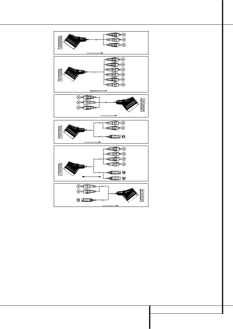
Installation and Connections
|
Blackck |
|
Figure 1: |
Yellowow |
|
SCART/Cinch-Adapter for |
||
Red |
||
playback; |
||
signal flow: |
|
|
SCART → Cinch |
|
|
|
Black |
|
|
Red |
|
|
Blue1 |
|
|
l |
|
Figure 2: |
Yellow |
|
n 1 |
||
SCART/Cinch-Adapter for |
||
Green |
||
record and playback; |
White |
|
signal flow: |
|
|
SCART ↔ Cinch |
|
|
|
Black |
|
Figure 3: |
Yellow |
|
Cinch/SCART-Adapter for |
Red |
|
playback; |
||
|
||
signal flow: |
|
|
Cinch → SCART |
|
|
|
ot |
|
|
Red |
|
Figure 4: |
Schwarz |
|
SCART/S-Video Adapter |
Black |
|
|
||
for playback; |
In |
|
signal flow: |
S-Video In |
|
|
||
SCART → Cinch |
|
Figure 5:
SCART/S-Video Adapter
for record and playback;
signal flow:
SCART ↔ Cinch
Figure 6:
SCART/S-Video Adapter
for playback;
signal flow:
Cinch → SCART
BlackSchwarz
RedRot
BlueBlau1
YellowGelb
SS--VideoInIn
SS--VideoOut
Rot
Red
SchwarzBlack
SS--VideoOut
1 Also other colours possible, e.g. brown and grey.
Important Note for the Use of SCART-Cinch Adapters:
When video sources are connected to the TV directly with a SCART cable, specific control signals apart from Audio/Video signals will be fed to the TV. These specific signals are: With all video sources, the signal for automatic input selection that switches the TV automatically to the appropriate input as soon as the video source is started. And with DVD players, the signals automatically turning the TV to 4:3/16:9 format (with 16:9 TVs or with 4:3 TVs with selectable 16:9 format) and turning the RGB video decoder of the TV on or off, depending on the DVD player´s setting. With any adapter cable, these control signals will be lost and the appropriate setting of the TV must be made manually.
Note for RGB signal with SCART:
If you use a unit providing RGB signals on a SCART output (as e.g. most DVD players do) and you want to use that RGB signal, this SCART output must be connected directly to your TV. Although the AVR 4500 RDS can switch threeway video signals (like component signals Y/Pb/Pr), most TVs need separate sync signals for RGB (also with SCART) that cannot be switched and provided by the AVR 4500.
RGB signals can be pathed through
the AVR 4500 only when no separate sync signal is needed (see last ”Video Connection Note” on page 16).
INSTALLATION AND CONNECTIONS 17

Installation and Connections
System and Power Connections
The AVR 4500 is designed for flexible use with multiroom systems, external control components and power amplifiers.
Main Room Remote Control Extension
If the receiver is placed behind a solid or smoked glass cabinet door, the obstruction may prevent the remote sensor from receiving commands. In this event, the remote sensor of any Harman Kardon or other compatible device, not covered by the door, or an optional remote sensor may be used. Connect the Remote IR Output of that device or the output of the remote sensor to the Remote IR Input jack .
If other components are also prevented from receiving remote commands, only one sensor is needed. Simply use this unit’s sensor or a remote eye by running a connection from the Remote IR Output jack to the Remote IR Input jack on Harman Kardon or other compatible equipment.
Multiroom IR Link
The key to remote room operation is to link the remote room to the AVR 4500’s location with wire for an infrared receiver and speakers or an amplifier. The remote room IR receiver (this can be an optional IR receiver or any other remotable Harman Kardon device in the remote room with IR sensor integrated) should be connected to the AVR 4500 via standard coaxial cable. Connect the Remote IR Output of the device or of the optional sensor with the Multiroom IR Input jack on the AVR4500’s rear panel.
If other Harman Kardon compatible source equipment is part of the main room installation, the Remote IR Output jack on the rear panel should be connected to the IR IN jack on that source device. This will enable the remote room location to control source equipment functions.
NOTE: All remotely controlled components must be linked together in a “daisy chain”. Connect the IR OUT jack of one unit to the IR IN of the next to establish this chain.
Multiroom Audio Connections
Depending on the distance from the AVR 4500 to the remote room, two options are available for audio connection:
Option 1: Use high-quality, shielded audio interconnect phono cable from the AVR 4500’s location to the remote room. In the remote room, connect the interconnect cable to a stereo power amplifier. The amplifier will be connected to the room’s speakers. At the AVR 4500, plug the audio interconnect cables into the
Multiroom Output Jacks on the AVR 4500’s rear panel.
Option 2: Place the amplifier that will provide power to the remote location speakers in the same room as the AVR 4500, and connect the Multiroom Output jacks on the rear panel of the AVR to the audio input of the remote room amplifier. Use the appropriate speaker wire to connect the optional power amplifier to the remote speakers. High-quality wire of at least 2.5 mm2 is recommended for long multiroom connections.
NOTE: In both options, you may connect an optional IR sensor in the remote room to the AVR 4500 via an appropriate cable. Connect the sensor’s cable to the Multiroom IR Input on the AVR 4500 and use the Zone II remote to control the room volume. Alternatively, you may install an optional volume control between the output of the amplifiers and the speakers.
External Audio Power Amplifier Connections
If desired, the AVR 4500 may be connected to optional, external audio power amplifiers. When an external amplifier is used, connect the Preamp Out jacks to the inputs on the amplifier. Note that when external amplifiers or devices are used, volume is still controlled by the AVR, although additional volume controls on the external device may affect volume and output levels from the AVR.
AC Power Connections
This unit is equipped with two accessory AC outlets. They may be used to power accessory devices, but they should not be used with highcurrent draw equipment such as power amplifiers. The total power draw to the Unswitched Outlet must not exceed 100 watts, that to the Switched Outlet 50 watts.
The Switched outlet will receive power only when the unit is on completely. This is recommended for devices that have no power switch or a mechanical power switch that may be left in the “ON” position.
NOTE: Many audio and video products go into a Standby mode when they are used with switched outlets, and cannot be fully turned on using the outlet alone without a remote control command.
The Unswitched outlet will receive power as long as the unit is plugged into a powered AC outlet and the Main Power Switch 1is on.
Finally, when all connections are complete, plug the power cord into a nonswitched 220-240-volt AC wall outlet. You’re almost ready to enjoy the AVR 4500!
18 INSTALLATION AND CONNECTIONS
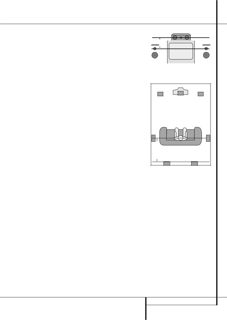
Installation and Connections
Speaker Selection
No matter which type or brand of speakers is used, the same model or brand of speaker should be used for the front-left, center and front-right speakers. This creates a seamless front soundstage and eliminates the possibility of distracting sonic disturbances that occur when a sound moves across mismatched front-channel speakers.
Speaker Placement
The placement of speakers in a multichannel home-theater system can have a noticeable impact on the quality of sound reproduced.
Depending on the type of center-channel speaker in use and your viewing device, place the center speaker either directly above or below your TV, or in the center behind a perforated front-projection screen.
Once the center-channel speaker is installed, position the left-front and right-front speakers so that they are as far away from one another as the center-channel speaker is from the preferred listening position. Ideally, the front-channel speakers should be placed so that their tweeters are no more than 60cm above or below the tweeter in the center-channel speaker.
They should also be at least 0.5 meter from your TV set unless the speakers are magnetically shielded to avoid colourings on the TV screen. Note that most speakers are not shielded, even with complete surround sets only the Center speaker may be.
Depending on the specifics of your room acoustics and the type of speakers in use, you may find that imaging is improved by moving the front-left and front-right speakers slightly forward of the center-channel speaker. If possible, adjust all front loudspeakers so that they are aimed at ear height when you are seated in the listening position.
Using these guidelines, you’ll find that it takes some experimentation to find the correct location for the front speakers in your particular installation. Don’t be afraid to move things around until the system sounds correct. Optimize your speakers so that audio transitions across the front of the room sound smooth.
When the AVR 4500 is used in 5.1-channel operation, the preferred location for surround speakers is on the side walls of the room, at or slightly behind the listening position. In a 7.1-channel system, both side surround and back surround speakers are required. The center of the speaker should face you (see below).
Rear surround speakers are required when a full 7.1-channel system is installed, and they may also be used in 5.1 channel mode as an alternative mounting position when it is not practical to place the main surround speakers at the sides of the room. Speakers may be placed on a rear wall, behind the listening position. As with the side speakers, the center of the rear surrounds should face you. The speakers should be no more than 2 meters behind the rear of the seating area.
Subwoofers produce largely nondirectional sound, so they may be placed almost anywhere in a room. Actual placement should be based on room size and shape and the type of subwoofer used. One method of finding the optimal location for a subwoofer is to begin by placing it in the front of the room, about 15cm from a wall, or near the front corner of the room. Another method is to temporarily place the subwoofer in the spot where you will normally sit, and then walk around the room until you find a spot where the subwoofer sounds best. Place the subwoofer in that spot. You should also follow the instructions of the subwoofer’s manufacturer, or you may wish to experiment with the best location for a subwoofer in your listening room.
Center Front Speaker
No more than 60cm
60cm
|
|
|
|
|
|
|
|
|
|
|
|
Left Front |
|
Right Front |
|||
Speaker |
|
Speaker |
|||
A) Front Channel Speaker Installation with Direct-View TV Sets or Rear-Screen Projectors
|
|
|
TV or Projection Screen |
|
|
Left Front |
Center Front |
Right Front |
|
|
Speaker |
|||
|
Speaker |
Speaker |
||
|
|
|||
than 2m |
-mounted |
are used |
|
|
No more |
when rear |
speakers |
|
|
|
|
|
Optional Rear-Wall Mounting |
|
B) The distance between the left and right speakers should be equal to the distance from the seating position to the viewing screen. You may also experiment with placing the left
and right speakers slightly forward of the center speaker.
Rear speaker mounting is an alternate location for 5.1 systems. It is required for 7.1 operation.
INSTALLATION AND CONNECTIONS 19
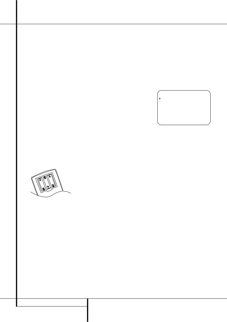
System Configuration
Once the speakers have been placed in the room and connected, the remaining steps are to program the system configuration memories. With the AVR 4500 two kind of memories are used, those associated individually with the input selected, e.g. surround modes, and others working independently from any input selected like speaker output levels, crossover frequencies or delay times used by the surround sound processor.
First Turn On
You are now ready to power up the AVR 4500 to begin these final adjustments.
1.Plug the Power Cable into an unswitched AC outlet.
2.Press the Main Power Switch 1in until it latches and the word “OFF” on the top of the switch disappears inside the front panel. Note that the Power Indicator 3 will turn orange, indicating that the unit is in the Standby mode.
3.Remove the protective plastic film from the main front-panel lens. If left in place, the film may affect the performance of your remote control.
4.Install the three supplied AAA batteries in the remote as shown. Be certain to follow the (+) and (–) polarity indicators that are on the top of the battery compartment.
5.Turn the AVR4500 on either by pressing the
System Power Control 2or the Input Source Selector %on the front panel, or via the remote by pressing the Power On Button
3, AVR Selector 5or any of the Input Selectors 46on the remote. The Power Indicator 3will turn green to confirm that the unit is on, and the Main Information Display ˜will also light up.
NOTE: After pressing one of the Input Selector buttons 4to turn the unit on, press the AVR Selector 5to have the remote control the AVR functions.
Using the On-Screen Display
When making the following adjustments, you may find them easier to make via the unit’s on-screen display system. These easy-to-read displays give you a clear picture of the current status of the unit and facilitate speaker, delay, input or digital selection you are making.
To view the on-screen displays, make certain you have made a connection from the Video Monitor Out jack on the rear panel to the composite or S-Video input of your TV or projector. In order to view the AVR’s displays, the correct video input must be selected on your video display. Note that the on-screen menus are not available when a component video display is in use.
IMPORTANT NOTE: When viewing the on-screen menus using a CRT-based projector, plasma display or any direct-view CRT monitor or television, it is important that they not be left on the screen for an extended period of time. As with any video display, but particularly with projectors, constant display of a static image such as these menus or video game images may cause the image to be permanently “burned into” the CRT. This type of damage is not covered by the AVR 4500 warranty and may not be covered by the projector TV set’s warranty.
The AVR 4500 has two on-screen display modes, “Semi-OSD” and “Full-OSD.” When making configuration adjustments, it is recommended that the Full-OSD mode be used. This will place a complete status report or option listing on the screen, making it easier to view the available options and make the settings on the screen. The Semi-OSD mode uses one-line displays only.
Note that when the full OSD system is in use, the menu selections are not shown in the Information Display ˜Y. When the full OSD menu system is used, OSD ON will appear in the
Main Information Display Yand the OSD Indicator Pwill illuminate to remind you that a video display must be used.
When the semi-OSD system is used in conjunction with the discrete configuration buttons, the on screen display will show a single line of text with the current menu selection. That selection will also be shown in the Main Information Display Y.
The full OSD system is always available by pressing the OSD button L. When this button is pressed the MASTER MENU (Figure 1) will appear, and adjustments are made from the individual menus. Note that the menus will remain on the screen for 20 seconds after the latest action was made on the screen menu, then they will “time-out” and disappear from the screen. The time-out may be increased to as much as 50 seconds by going to the ADVANCED
SELECT menu, and changing the item titled
FULL OSD TIME OUT.
The semi-OSD system is also available as a system default, although it may be turned off by using the ADVANCED SELECT menu. (See page 37). With the semi-OSD system, you may make adjustments directly, by pressing the buttons on the front panel or remote control for the specific parameter to be adjusted. For example, to change the digital input for any of the sources, press the Digital Select Button ÛGand then any of the Selector buttons ‹/› 7$or
⁄/¤ Don the front panel or remote.
* M A S T E R M E N U *
I N / O U T S E T U P
S U R R O U N D S E T U P
S P E A K E R S E T U P
D E L A Y A D J U S T
C H A N N E L A D J U S T
M U L T I - R O O M
A D V A N C E D
Figure 1
Settings to be Made Individually for Each Input in Use
The AVR 4500 features an advanced memory system that enables you to establish different setting for the speaker configuration, digital input and surround mode for each input source. This flexibility enables you to custom tailor the way in which you listen to each source and have the AVR 4500 memorize them. This means, for example, that you may associate different surround modes and analog or digital inputs with different sources, or set different speaker configurations with the resultant changes to the bass management system or the use of the center speaker and/or the Subwoofer. Once these settings are made, they will automatically be recalled whenever you select that input.
The factory default settings for the AVR 4500 have all inputs configured for an analog audio input except for the DVD input, where the
Coaxial Digital Input $ is the default. Once the DSP processing system is used for the first time for any input, the speaker settings will automatically default to “Small” at all positions with the subwoofer set to “LFE.” The default setting for the surround modes is “Surround Off,” or twochannel stereo, although Dolby Digital or DTS will automatically be selected as appropriate when a source with digital encoding is in use.
Before using the unit, you will probably want to change the settings for most inputs so that they are properly configured to reflect the use of digital or analog inputs, the type of speakers installed and the surround mode associated with the input. Remember that since the AVR 4500 memorizes
20 SYSTEM CONFIGURATION
System Configuration
the settings for each input individually, you will need to make these adjustments for each input used. However, once they are made, further adjustment is only required when system components are changed.
To make this process as quick and as easy as possible, we suggest that you use the full-OSD system with the on-screen menus, and step through each input. Once you have completed the settings for the first input, many settings may be duplicated for the remaining inputs.
The items that follow will describe the individual settings required for each input. Remember that once the settings are made for one input, they must be made for all other input sources in your system.
Input Setup
The first step in configuring the AVR4500 is to select an input, i.e. to associate an analog or digital input with each input source in use, e.g. CD or DVD. This may be done by pressing the front panel Input Source Selector %until the desired input’s name appears momentarily in the
Main Information Display Y, and the green LED lights next to the input’s name in the front panel Input Indicators ˆ. The input may also be selected by pressing the appropriate Input Selector on the remote control 46.
When using the full-OSD system to make the setup adjustments, press the OSD button L once so that the MASTER MENU (Figure 1) appears. Note that the › cursor will be next to the IN/OUT SETUP line. Press the Set button Fto enter the menu and the IN/OUT SETUP menu (Figure 2) will appear on the screen. Press the ‹/› buttons E%until the desired input name appears in the highlighted video, as well as being indicated in the front panel Input Indicators ˆby the green LED next to the desired input name. If the input will use the standard left/right analog inputs, no further adjustment is needed (except with DVD).
* I N / O U T S E T U P |
* |
|
|||
|
|
|
|
|
|
I N P U T |
: |
V I D E O |
1 |
|
|
|
|
|
|
|
|
D I G I T A L |
I N : |
A N A L O G |
|
|
|
|
|
|
|
||
C O A X I A L |
3 : |
I N |
O U T |
|
|
B A C K T O |
M A S T E R M E N U |
||||
|
|
|
|
|
|
Figure 2
If you wish to associate one of the digital inputs with the selected input source, press the ¤ Button Don the remote while the IN/OUT SETUP menu (Figure 2) is on the screen, and note that the on-screen cursor will drop down to the DIGITAL IN line.
Press the ‹/› Buttons E%until the name of the desired digital input appears. To return to the Analog input, press the buttons until the word ANALOG appears. When the correct input source appears, press the ¤ button D until the › cursor appears next to BACK TO MASTER MENU, and press the Set Button
F.
To associate an analog or digital input with the input source currently selected at any time using the discrete function buttons, press the Digital Input Select Button ÚGon the front panel or the remote while the full-OSD is not in use. Within five seconds, make your input selection using the Selector buttons on the front panel 7$or the ⁄/¤ DButtons on the remote until the desired digital or analog input is shown in the Main Information Display Yand in the lower third of the video display connected to the AVR 4500. Press the Set Button Fto enter the new input assignment.
An exclusive Harman Kardon feature is the ability to switch front panel jacks from their normal use as inputs to output connections so that portable recording devices may easily be connected.
On the AVR 4500, the Coaxial 3 Digital Jack
Óis normally an input, but it may also be switched to a digital output for use with CD- R/RW decks, MD recorders or other digital audio recorders. To change the jack to an output, press the ⁄/¤ buttons Dwhile the IN/OUT SETUP menu is on the screen so that the › cursor is next to COAXIAL 3. Then press the ‹/› buttons E/%so that the word OUT is highlighted. Note that the Digital Coax 3 Status Indicator (will turn red, indicating that the jack is now a record output.
Note: A signal will be sent to this jack only when the input selected for use by the AVR 4500 is digital. Digital signals will be passed through regardless of their format, and which digital input (optical or coax) they are fed from. However, analog signals are not converted to digital, and the format of the signal (e.g., PCM, Dolby Digital or DTS) may not be changed.
Selection of the jack as an output will remain effective as long as the AVR 4500 is on. However, once the unit is turned off, the jack will revert to its normal use as an input when the unit is turned on again.
Speaker Setup
This menu tells the AVR 4500 which type of speakers are in use. This is important as it adjusts the settings that determine which speakers receive low-frequency (bass) information. For each of these settings use the LARGE setting if the speakers for a particular position are traditional full-range loudspeakers that are capable of reproducing sounds below 100Hz. Use
the SMALL setting for smaller, frequencylimited satellite speakers that do not reproduce sounds below 100Hz. Note that when “small” speakers are used, a subwoofer is required to reproduce low-frequency sounds. Remember that the “large” and “small” descriptions do not refer to the actual physical size of the speakers, but to their ability to reproduce low-frequency sounds. If you are in doubt as to which category describes your speakers, consult the specifications in the speakers’ owner’s manual, or ask your dealer.
Notes:
•As the speaker settings need to be made for each input individually, you can determine which speaker should be used depending on the input source selected. So it´s possible e.g. to turn off the Center and/or the Sub with any music source selected and to use them with any movie input source.
•With the currently selected input all speaker settings will be copied to all other surround modes (as far as speakers are used with them) and need not be repeated when another surround mode is selected with that input.
To start with the speaker setting, first select any of the DTS Neo:6 modes as with them all speakers and all speaker modes are available. It is easiest to select these modes directly, without the onscreen display, so press the OSD button Lto turn the on-screen display off if it is still visible. Then press the DTS Neo:6 button &on the front panel or on the remote.
1. It is easiest to enter the proper settings for the speaker setup through the SPEAKER SETUP menu (Figure 3). So press the OSD Button Lto bring up the MASTER MENU (Figure 1), and then press the ¤ Button Dtwice so that the cursor is on the SPEAKER SETUP line. At this point, press the Set Button Fto bring up the SPEAKER SETUP menu (Figure 3).
* S P E A K E R |
S E T U P * |
|
|
|
|
L E F T / R I G H T : |
S M A L L |
|
|
|
|
C E N T E R |
: |
S M A L L |
|
|
|
S U R R O U N D |
: |
S M A L L |
|
|
|
S U R R B A C K |
: |
S M A L L |
|
|
|
S U B W O O F E R |
: |
S U B |
S U B |
X - O V E R |
F R E Q : 8 0 |
H Z |
B A C K T O M A S T E R M E N U |
|||
Figure 3
SYSTEM CONFIGURATION 21
 Loading...