


CDR-26
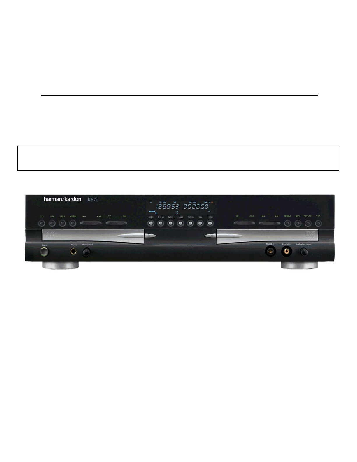
harman/kardon
CDR25
CDR26
Dual Tray CD-R/CD-RW Recorder/Player
PRELIMINARY SERVICE MANUAL
CONTENTS
SPECIFICATIONS . . . . . . . . . . . . . . . . . . . .. . . . 2
SERVICING PRECAUTIONS . . . . . . . . ... . . .. . 3
ESD PRECAUTIONS . . . . . . . . . . . . . . . . . .. . . 5
SPECIAL NOTE ON CDR26 RECORDING. . .. . 6
FRONT PANEL CONTROLS ……….. . . .. . . .. . 7
FRONT PANEL DISPLAY ……….. . . .. . . . . . . 9
REAR PANEL CONNECTIONS. . . . . . . . . . .. . 11
REMOTE CONTROL FUNCTIONS. . . . . .. .. …12
INSTALLATION/CONNECTIONS. . . . . . . .. . …14
BASIC TROUBLESHOOTING GUIDE &
WIRING DIAGRAMS . . . . . . . . .. . . . ... . . . . . . 17
BLOCK DIAGRAMS . . . . . . . . .. . . .. . .. .. . . . .19
DETAILED TROUBLESHOOTING GUIDE …….24
WAVEFORMS. . . . . . . . . . . . . . . . . . …………. 47
EXPLODED VIEWS . . . . . . . . . . . .. . .. . .. . . . . 49
MECHANICAL PARTS LIST……….. .. . . . . . .. . 52
ELECTRICAL PARTS LIST . . . . . .. . . ..… …….54
PCB DRAWINGS. . . . . . . . . . . . ….. . .. . . . .. . . 71
SCHEMATIC DIAGRAMS . . . . . . . . . . . .. . . . . 74
ERROR MESSAGES . . . ………………………. 16
harman/kardon, Inc.
250 Crossways Park Dr.
Woodbury, New York 11797

Signal Format
Playback Sampling Frequency 44.1kHz
D/A Conversion 96kHz, Multi-Bit Delta-Sigma Conversion
Oversampling 128 Times
Playback Specifications
Frequency Response 2Hz – 20,050Hz
Playback S/N 100dB
Playback Dynamic Range 95dB
Playback THD 0.01%/0dB
Analog Audio Output 2V RMS,± 2dB
Digital-Coaxial Output 0.5Vpp/75Ω
Headphone Output 1V RMS/32Ω Load
Record Specifications
Digital Input Sample Rates 32kHz – 96kHz
Recording S/N: Analog 80dB
Recording S/N: Digital Dub Mode Equal to Source
Recording S/N: Digital External Source Source –10dB
Recording Dynamic Range 90dB
Recording THD 0.01%/0dB
Analog Input Sensitivity 330mV RMS 47kΩ = 0dB
Digital Inputs (Direct Recording) 44.1kHz, ±100 ppm/min.
General
Power Requirement 110~240 VAC/50~60Hz
Power Consumption 20 Watts
Dimensions
Width 17-5/16"/440mm
Height 4-7/16"/112mm
Depth 13-15/16"/355mm
Weight 13 lb/5.8kg
Depth measurement includes knobs,buttons and connection jacks.
Height measurement includes feet and chassis.
All features and specifications are subject to change without notice.
Harman Kardon and Power for the Digital Revolution
are registered trademarks of Harman Kardon, Inc.
DTS is a registered trademark of Digital Theater Systems,Inc.
CDR 26 TECHNICAL SPECIFICATIONS
2
-3-
SERVICING PRECAUTIONS
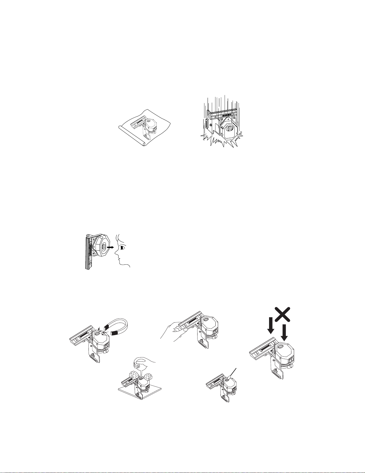
NOTES REGARDING HANDLING OF THE PICK-UP
1. Notes for transport and storage
1) The pick-up should always be left in its conductive bag until immediately prior to use.
2) The pick-up should never be subjected to external pressure or impact.
2. Repair notes
1) The pick-up incorporates a strong magnet, and so should never be brought close to magnetic materials.
2) The pick-up should always be handled correctly and carefully, taking care to avoid external pressure and
impact. If it is subjected to strong pressure or impact, the result may be an operational malfunction
and/or damage to the printed-circuit board.
3) Each and every pick-up is already individually adjusted to a high degree of precision, and for that reason
the adjustment point and installation
screws should absolutely never be touched.
4) Laser beams may damage the eyes!
Absolutely never permit laser beams to enter the eyes!
Also NEVER switch ON the power to the laser output part (lens, etc.) of the pick-up if it is damaged.
5) Cleaning the lens surface
If there is dust on the lens surface, the dust should be cleaned away by using an air bush (such as used
for camera lens). The lens is held by a delicate spring. When cleaning the lens surface, therefore, a cot-
ton swab should be used, taking care not to distort this.
6) Never attempt to disassemble the pick-up.
Spring by excess pressure. If the lens is extremely dirty, apply isopropyl alcohol to the cotton swab. (Do
not use any other liquid cleaners, because they will damage the lens.) Take care not to use too much of
this alcohol on the swab, and do not allow the alcohol to get inside the pick-up.
Storage in conductive bag
NEVER look directly at the laser beam, and don’t let contact
fingers or other exposed skin.
Magnet
How to hold the pick-up
Conductive Sheet
Cotton swab
Pressure
Pressure
Drop impact
-4-
NOTES REGARDING COMPACT DISC PLAYER REPAIRS
1. Preparations
1) Compact disc players incorporate a great many ICs as well as the pick-up (laser diode). These compo-
nents are sensitive to, and easily affected by, static electricity. If such static electricity is high voltage,
components can be damaged, and for that reason components should be handled with care.
2) The pick-up is composed of many optical components and other high-precision components. Care must
be taken, therefore, to avoid repair or storage where the temperature of humidity is high, where strong
magnetism is present, or where there is excessive dust.
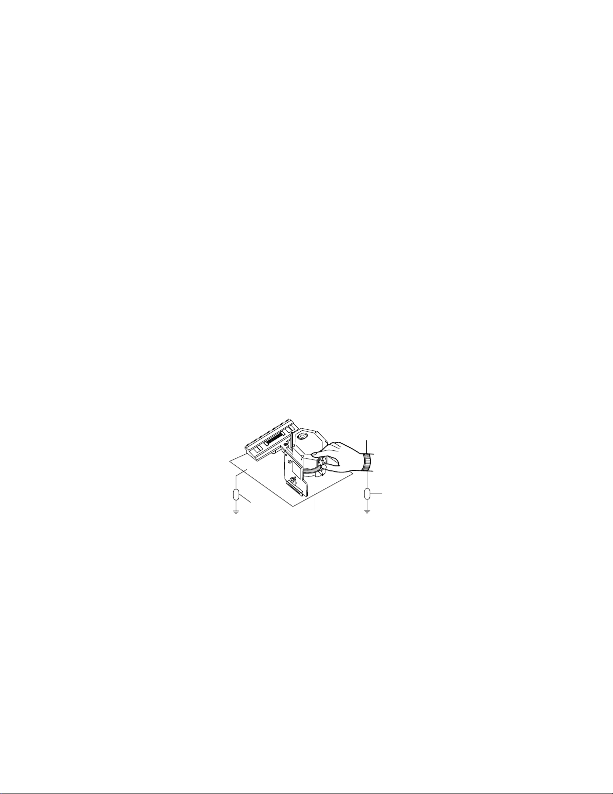
2. Notes for repair
1) Before replacing a component part, first disconnect the power supply lead wire from the unit
2) All equipment, measuring instruments and tools must be grounded.
3) The workbench should be covered with a conductive sheet and grounded.
When removing the laser pick-up from its conductive bag, do not place the pick-up on the bag. (This is
because there is the possibility of damage by static electricity.)
4) To prevent AC leakage, the metal part of the soldering iron should be grounded.
5) Workers should be grounded by an armband (1MΩ)
6) Care should be taken not to permit the laser pick-up to come in contact with clothing, in order to prevent
static electricity changes in the clothing to escape from the armband.
7) The laser beam from the pick-up should NEVER be directly facing the eyes or bare skin.
Resistor
(1 Mohm)
Conductive
Sheet
Resistor
(1 Mohm)
Armband

-5-
ESD PRECAUTIONS
Electrostatically Sensitive Devices (ESD)
Some semiconductor (solid state) devices can be damaged easily by static electricity. Such components com-
monly are called Electrostatically Sensitive Devices (ESD). Examples of typical ESD devices are integrated cir-
cuits and some field-effect transistors and semiconductor chip components. The following techniques should
be used to help reduce the incidence of component damage caused by static electricity.
1. Immediately before handling any semiconductor component or semiconductor-equipped assembly, drain off
any electrostatic charge on your body by touching a known earth ground. Alternatively, obtain and wear a
commercially available discharging wrist strap device, which should be removed for potential shock reasons
prior to applying power to the unit under test.
2. After removing an electrical assembly equipped with ESD devices, place the assembly on a conductive sur-
face such as aluminum foil, to prevent electrostatic charge buildup or exposure of the assembly.
3. Use only a grounded-tip soldering iron to solder or unsolder ESD devices.
4. Use only an anti-static solder removal device. Some solder removal devices not classified as "anti-static"
can generate electrical charges sufficient to damage ESD devices.
5. Do not use freon-propelled chemicals. These can generate electrical charges sufficient to damage ESD
devices.
6. Do not remove a replacement ESD device from its protective package until immediately before you are
ready to install it. (Most replacement ESD devices are packaged with leads electrically shorted together by
conductive foam, aluminum foil or comparable conductive materials).
7. Immediately before removing the protective material from the leads of a replacement ESD device, touch the
protective material to the chassis or circuit assembly into which the device will by installed.
CAUTION : BE SURE NO POWER IS APPLIED TO THE CHASSIS OR CIRCUIT, AND OBSERVE ALL
OTHER SAFETY PRECAUTIONS.
8. Minimize bodily motions when handing unpackaged replacement ESD devices. (Otherwise harmless motion
such as the brushing together of your clothes fabric or the lifting of your foot from a carpeted floor can gen-
erate static electricity sufficient to damage an ESD device).

CDR 26 SPECIAL NOTICE
Under certain circumstances, the CDR 26 may operate differently than the description in
the owner’s manual.
In particular, the unit will not be able to make a digital recording from an external
source such as a CD player, DVD player or MiniDisc (MD) player (as shown on
page 20 of the owner’s manual) when that player blocks a special electrical signal,
called “Sub-Q,” from the digital output. This signal contains some of the data
needed to tell the CDR 26 that the original disc has started playing, and without it
the CDR 26 cannot begin a recording.
This is outside of our control, as some manufacturers design products this way to
prevent digital copies from being made. Should you find that a digital recording cannot
be made from an external playback source, you may always use an analog connection
to make the copy by pressing the Input Select Button on the front panel or remote
control until ANALOG appears in the Information Display.
This does not affect the CDR 26’s ability to make high-speed dubs using the unit’s own
internal playback deck, and in many cases you will not encounter this problem at all,
since it is related to the brand of playback deck being used.
6
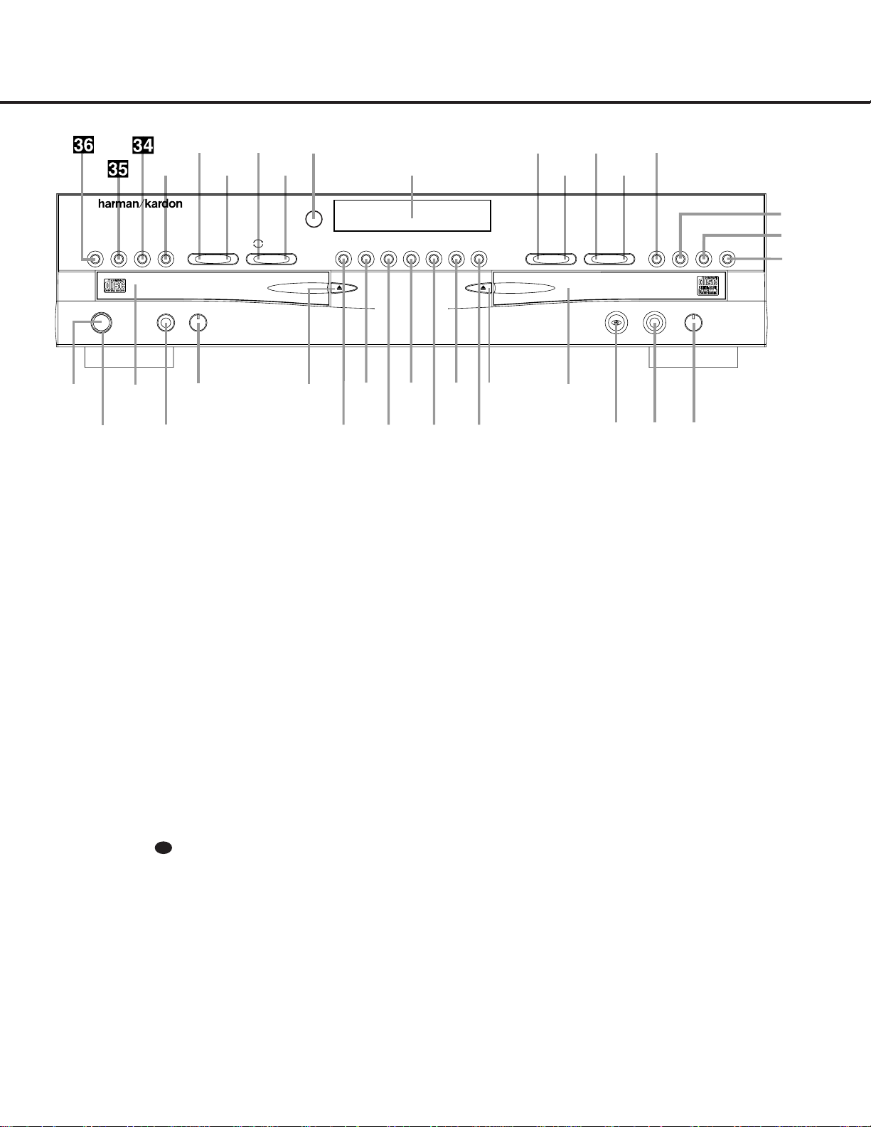
FRONT-PANEL CONTROLS
1 Power Switch: Press this switch to apply power
to the CDR 26.When the unit is first turned on, the
Status Mode Indicator 2 surrounding the switch
will turn green. Once the unit has been turned on with
this switch, it may be operated from either the front
panel or remote control. Press the switch again to turn
the unit completely off.
2 Status Mode Indicator: When the CDR 26 is in
the ON mode,this indicator will glow green.When the
unit has been placed in the Standby mode by pressing
the
Power-Off Button on the remote,the indi-
cator will glow amber,indicating that the unit is still
connected to the AC main supply and is ready to be
turned on from the remote control.
3 Play Deck: This disc deck is used to play back
conventional CD discs and CD-R or CD-RW discs that
have been finalized.
4 Headphone Jack: Connect standard headphones
to this jack for private listening.
5 Headphone Level Control: Turn this control to
adjust the volume level to the headphones.Note that
the use of this control will not change the analog out-
put levels at the rear-panel audio output
¡.
6 Play-Deck Open: Press this button to open the
Play Deck 3.
7 Record Button: Press this button to begin the
recording process.See pages 19–22 for more infor-
mation on CD recording.
8 Synchronous Recording (CD Sync) Button:
Press this button once to begin an automated record-
ing of a single track from an external CD player when
a digital connection is used. Press it twice to begin
automated recording of an entire disc.See page 20
for more information on CD Sync recording.
9 Dubbing: Press this button to begin the process
of making a complete copy of the disc in the
Play
Deck
3 to a CD-R or CD-RW disc in the Record
Deck
%. See page 19 for more information on
dubbing.
) Speed: Press this button to select the recording
speed for internal dubs.See page 19 for more infor-
mation on selecting the proper speed.
! Track Increment: Press this button during
recording to insert a new track marker at that point
in the recording.The current track number will be
incremented by one.
@ Erase: Press this button to erase one or more
tracks or the entire contents of an unfinalized CD-RW
disc.When a CD-RW disc has already been finalized
you may erase the entire disc or you may “unfinalize”
the disc by erasing the
TOC data. See page 21 for
more information on erasing CD-RW discs.
# Finalize: Press this button when a recording
is complete to initiate the finalization process.The
Play/Select Button Ój must be pressed within
three seconds to activate finalization. Until this button
is pressed and the finalization process is complete,
CD-R discs may not be played on conventional CD
machines.See page 21 for more information on
finalization.
30
1 Power Switch
2 Status Mode Indicator
3 Play Deck
4 Headphone Jack
5 Headphone Level Control
6 Play-Deck Open
7 Record Button
8 Synchronous Recording (CD Sync) Button
9 Dubbing
) Speed
! Track Increment
@ Erase
# Finalize
$ Record-Deck Open
% Record Deck
^ Optical Digital Input
& Coaxial Digital Input
* Analog-Record Level Control
( Record-Deck Stop
Ó Record-Deck Play/Select
Ô Record-Deck Pause
Record-Deck Program Button
Ò Record-Deck Next
Ú Record-Deck Previous
Û Input Select
Ù Record-Deck Time Display Select
ı Infor mation Display
ˆ Remote Sensor
˜ Play-Deck Time Display Select
¯ Continuous Play
˘ Play-Deck Next
¸ Play-Deck Previous
˝ Play-Deck Program Button
Play-Deck Pause
Play-Deck Play
Play-Deck Stop
STOP
CDR 26
PLAY PAUSE PROGRAM
Í
‹‹ ››
Í Í
‹‹ ››
Í
TIME Record
Power Phones Phones Level Optical In
Sync Rec. Dubbing Track Inc.Speed Erase Finalize TIME INPUT PROGRAM
2
1
3
5
6
7
8
9
)
!
#
@
$
%
*
&^
4
Ó
Ú
Û
Ù
ı
ˆ
˜
¯
¸
˝˘
Ô
Ò
(
PAUSE PLAY/SELECT STOP
Coaxial In Analog Rec. Level
FRONT-PANEL CONTROLS
5
7

$ Record-Deck Open: Press this button to open
the
Record Deck %.
% Record Deck: This disc deck is used to record
or play back CD,CD-R and CD-RW discs.
^ Optical Digital Input: This optical digital input
may be used to connect a portable digital audio player
to the CDR 26 for digital recording.Remove the dust
cap before connecting a cable to this jack. Keep the
dust cap in a safe place and replace it when the cable
is disconnected in order to prevent the possibility of
dust getting into the jack and damaging it.
& Coaxial Digital Input: This coaxial digital input
may be used to connect a portable digital audio player
to the CDR 26 for digital recording.
* Analog-Record Level Control: The control is
used to adjust the input level when making recordings
from analog sources such as cassettes,or when CDs
are recorded in an analog mode.See page 21 for
more information on record levels.
( Record-Deck Stop: Press this button to stop the
CD in the Record Deck.
Ó Record-Deck Play/Select: This button has two
functions.It may be pressed when a standard CD is in
the Record Deck to put the machine in play,or it may
be used to enter a selection or start certain record
functions.
Ô Record-Deck Pause: When the Record Deck is
in the Play mode,pressing this button will pause the
disc.If the disc has previously been paused,pressing
this button will restart the playback.
Record-Deck Program Button: Press this but-
ton to begin the programming sequence for the
Record Deck. See page 18 for more information on
programming playlists on the CDR 26.
Ò Record-Deck Next: When a disc is playing in the
Record Deck %, press and hold this button to play
the disc in a fast-forward mode to quickly locate a
desired passage.At any time, tapping the button and
quickly releasing it will move to the next track on a
disc in play.
Ú Record Deck Previous: This button has two
functions.When a disc is playing in the
Record Deck
%, press and hold this button to play the disc in a
fast reverse mode to quickly locate a desired passage.
At any time,tapping the button and quickly releasing it
will move to the beginning of the current track, and
the next press will move to the previous track.When a
disc is stopped, each press will move back one for
programming or play when the disc is stopped. Once
a track is entered, it may be played by simply pressing
the
Play Button Ój.
Û Input Select: Press this button to select the input
source (analog or digital) for recording.See page 20
for more information on input selection.
Ù Record-Deck Time Display Select: Press this
button to cycle through the time display options for the
Record Deck. See page 17 for more information on
the time display.
ı Informa tion Display: The indicators in the
Information Display provide status reports on the oper-
ation of the CDR 26. See page 7 for complete expla-
nations of each indicator.
ˆ Remote Sensor: The IR sensor that receives the
commands from the remote control is behind this
area. Do not cover or obscure this part of the front
panel, to avoid any malfunction with the remote.
˜ Play-Deck Time Display Select: Press this but-
ton to cycle through the time display options for the
Play Deck. See page 17 for more information on the
time display.
¯ Continuous Play Button: Press this button to
place the CDR 26 in Continuous Play mode,which
causes it to alternate play between the discs in each
deck continuously,so long as the next deck to be
played contains a disc and play has not been stopped.
To return to the default Single Play mode,in which
play stops after the disc in the selected deck has
played once,press this button again.
˘ Play-Deck Next: When a disc is playing in the
Play Deck 3, press and hold this button to play the
disc in a fast-forward mode to quickly locate a desired
passage.At any time, tapping the button and quickly
releasing it will move to the next track on a disc
in play.
¸ Play-Deck Previous: This button has two func-
tions.When a disc is playing in the
Play Deck 3,
press and hold this button to play the disc in a fast-
reverse mode to quickly locate a desired passage.At
any time,tapping the button and quickly releasing it
will move to the beginning of the current track, and
the next press will move to the previous track.When a
disc is stopped, each press will move back one track
for programming or play when the disc is stopped.
Once a track is entered, it may be played by simply
pressing the
Play Button j.
˝ Play-Deck Program Button: Press this button to
begin the programming sequence for the Play Deck.
See page 18 for more information on programming
playlists on the CDR 26.
Play-Deck Pause: When the Play Deck is run-
ning,pressing this button will pause the disc.If the
disc has previously been paused, pressing this button
will restart the playback.
Play-Deck Play: Press this button to begin play-
back of a CD in the Play Deck or the dubbing process.
Play-Deck Stop: Press this button to stop the
CD in the Play Deck.
FRONT-PANEL CONTROLS
6 FRONT-PANEL CONTROLS
8

FRONT-PANEL INFORMATION DISPLAY
FRONT-PANEL INFORMATION DISPLAY 7
A LL -B
A LL -B
REM
TRK
REM
TRK
1 TR
C
U
W
L
N
O
P
V
YY
I
A
B
D
E
F
G
H
I
J
F
K
H
G
M
Q
R
S
T
V
X
T
W
R
O
A Coaxial Digital Indicator
B Optical Digital Indicator
C Analog Indicator
D Front-Panel Input Indicator
E Sync Indicator
F Repeat Indicators
G Random Indicators
H Repeat Status Indicators
I Program Indicators
J Level Indicators
K Speed Indicators
L 1-Track Dubbing Indicator
M Dubbing Indicator
N Sample-Rate Conversion Indicator
O Play/Pause Indicators
P Record Indicator
Q R/RW Indicator
R CD Indicators
S Time Indicators
T Remaining Time Indicators
U Recorded Time Indicator
V Total Time Indicators
W Track Time Indicators
X Manual Indicator
Y Infor mation Displays
Important Note: Since the CDR 26 is a dual-deck player/recorder,there are two separate sets of indicators for the Random, Program, Repeat, Repeat Status,Time,Total Time,
Remaining Time and Track Time.In addition,there is a separate Information Display,Play/Pause Indicator and CD Indicator for each deck.As the function of these indicators is
identical for both decks,they are described in this manual with a common letter.When the CDR 26 is playing or recording a disc, any indicators that light on the left side of the
display describe the status of the Play Deck, while those that light on the right side of the display describe the status of the Record Deck. Depending on the activity of the unit
and the settings you select, different indicators may light on the two sides at the same time.
A Coaxial Digital Indica tor: This indicator lights
when a digital source is being recorded. See page 20
for more information on source selection.
B Optical Digital Indica tor: This indicator lights
when a digital source connected to one of the optical
inputs is being recorded. See page 20 for more infor-
mation on source selection.
C Analog Indica tor: This indicator lights when an
analog source is being recorded. See page 20 for
more information on source selection.
D Front-Panel Input Indicator: This indicator lights
in conjunction with the
Coaxial Digital Indicator A
or the Optical Digital Indicator B when either the
front-panel coaxial or optical input has been selected.
See page 20 for more information on selecting an
external source.
E Sync Indica tor: This indicator lights when the unit
has been programmed for a CD Sync recording.See
page 20 for more information on CD Sync recordings.
F Repea t Indicators: These indicators light when a
repeat function is being used. See page 18 for more
information on repeat play.
G Random Indica tors: These indicators light when
random playback has been programmed for one of
the CD decks.See page 16 for more information on
random play.
H Repea t Status Indica tors: These indicators dis-
play the type of repeat function being used. See page
18 for more information on repeat status.
I Program Indica tors: These indicators light when
one of the CD decks is being programmed for play-
back options.See page 18 for more information on
programmed play.
J Level Indica tors: These LEDs display the input
level during an analog recording,and the output level
during playback. See page 21 for more information
on record levels.
K Speed Indica tors: These indicators show which
record speed has been selected for dub recordings.
See page 19 for more information on record-speed
selection.
L 1-Track Dubbing Indicator: This indicator lights
when a single track is being dubbed by itself,as
opposed to the entire disc or a programmed playlist.
See page 19 for more information on dubbing.
M Dubbing Indica tor: This indicator lights when a
dub is in progress between the two CD decks.See
page 19 for more information on CD dubbing.
9

8FRONT-PANEL INFORMATION DISPLAY
FRONT-PANEL INFORMATION DISPLAYFRONT-PANEL INFORMATION DISPLAY
N Sample-Ra te Conversion Indicator: This indica-
tor lights when the Sample-Rate Converter is in use to
change the digital sample rate when the incoming signal
is not the standard 44.1kHz used by standard CDs.This
is an automatic function and does not require any user
intervention.
O Play/Pause Indicators: These indicators show the
status of the individual CD decks.The
› lights when
the CD is playing,and the
›
±±
lights when the unit is in
a Pause mode.
P Record Indica tor: This indicator lights while the
unit is making a recording and flashes during the
preparations for recording.
Q R/R W Indica tor: This indicator shows which type
of recordable disc is present in the
Record Deck %.
When a CD-R disc is present, only the
R is lit. The RW
lights when an erasable CD-RW disc is in use.
R CD Indica tors: These indicators light when a stan-
dard CD is playing in either deck
3 or %.
S Time Indicators: These indicators light in conjunc-
tion with one of the time indicators
TUVW to
show which of the time status modes is active.
T Remaining Time Indicators: These indicators light
when the
Information Display Y shows the time
remaining on a disc.
U Recorded-Time Indicator: While a recording is
in progress,and up until a CD-R or CD-RW disc in the
Record Deck % has been finalized, this indicator will
light, and the
Information Display Y will indicate the
total amount of time recorded on the disc thus far.
V Total Time Indicators: These indicators light when
the
Information Display Y shows the total time of all
tracks on a disc.
W Track Time Indicators: These indicators light
when the
Information Display Y shows the running
time of the individual track being played.
X Manual Indica tor: This indicator lights when the
manual method of incrementing tracks is selected for a
recording session. See page 20 for more information
on track increments.
Y Informa tion Displays: These displays serve two
functions,showing the time displays for discs playing,
and displaying messages about discs or recordings.
10

REAR-PANEL CONNECTIONS 9
REAR-PANEL CONNECTIONS
¡
™
£
¢
ª
AC 110~240V, 50~60Hz 20W
MODEL NO. CDR 26
HARMAN KARDON
NORTHRIDGE
CALIFORNIA. USA
IN
¶
•
OPTICAL
OUT
∞
§
¡ Analog Output
™ Analog Input
£ Coaxial-Digital Output
¢ Coaxial-Digital Input
∞ Optical-Digital Input
§ Optical-Digital Output
¶ Remote IR Input
• Remote IR Output
ª AC Power Cord
¡ Analog Output: These jacks carry the analog
audio output signal from the deck currently playing.
Connect them to the Tape Play/In input jacks on a
receiver,preamp or processor.
™ Analog Input: These jacks accept the analog sig-
nals that are used for CD recordings.Connect them to
the Tape Rec/Play outputs on a receiver,preamp or
processor.
£ Coaxial-Digital Output: This jack carries the
digital-audio output signal from the deck currently
playing.Connect it to a coaxial-digital input on a
receiver,processor or digital decoder.
¢ Coaxial-Digital Input: This jack accepts the digi-
tal-audio input signal from a compatible digital audio
product and should be connected directly to a digital
player or to a coaxial-digital output on a CD or DVD
player or an A/V receiver or processor.
IMPORTANT NOTE:The coaxial digital input should
only be connected to
digital input or output jacks.
Even though it uses the same RCA-type connector as
standard analog audio connections,
DO NOT connect
it to conventional analog input or output jacks.
∞ Optical-Digital Input: This jack accepts the digi-
tal-audio input signal from a compatible digital audio
product, and should be connected to the optical-digital
output on a CD or DVD player or an A/V receiver or
processor.
§ Optical-Digital Output: This jack carries the opti-
cal digital output signal from the deck currently play-
ing.Connect it to an optical digital input on a receiver,
processor or digital recorder.
¶ Remote IR Input: Connect the output of a
remote infrared sensor or the remote control output of
another compatible Harman Kardon product to this
jack.This will enable the remote control to operate
even when the front-panel
Remote Sensor ˆ is
blocked.This jack may also be used with compatible
IR remote control-based automation systems.
• Remote IR Output: Connect this jack to the IR
input jack of another compatible Harman Kardon
remote-controlled product to have the built-in
Remote
Sensor
ˆ on the CDR 26 provide IR signals to
other compatible products.
ª AC Power Cord: Connect this plug to an AC out-
let. If the outlet is switch-controlled, make certain that
it is in the
ON position.
11
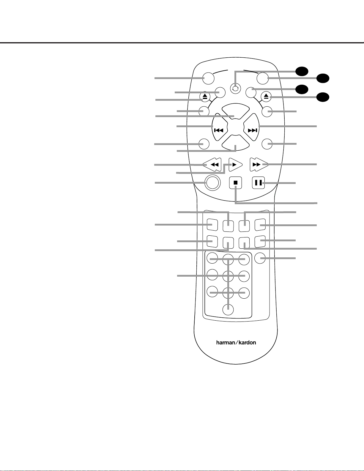
10 REMOTE CONTROL FUNCTIONS
REMOTE CONTROL FUNCTIONS
●
●
●
●
a Power On
b Play Deck (CDP) Time Display Control
c Play Deck (CDP) Open
d Play Deck (CDP) Select
e Program
f Previous-Track Skip
g Repeat
h Clear
i Reverse Search
j Play
k Random Play
l Dub
m Automatic/Manual Track Increment Selector
n Track Increment
o Finalize
p Numeric Keys
q Speed Select
r Record Button
s Erase Button
t Input Select
u CD Sync
v Stop
w Pause
x Forward Search
y A-B Repeat
z Next Track/Skip
` Record Deck (CDR) Select
28
Record Deck (CDR) Open
29
Record Deck (CDR) Time Display Control
30
Power Off
31
Continuous Play
32
IMPORTANT NOTE:Some of the remote’s func-
tions, including Play,Pause,Stop, Search, Next
and Previous Track,are shared between the two
decks.Always remember to press the
CDP
Select Button
d to use the remote to control
the Play Deck, or press the
CDR Select Button
` to control the Record Deck. When you press
one of these buttons, an indication of
CDP or
CDR will a ppear in the appropria te
Information Display Y.
ON
OFF
SEARCH
PLAY
SEARCH
STOP
PAUSE
PROG.
CLEAR
P
R
E
V
N
EX
T
POW
ER
REPEA T
RANDOM
A – B
TR INC
F
I
NAL
I
Z
E
I
N
P
UT
ER
AS
E
CD SYNC
REC
CDR/RW
l
a
b
c
d
g
h
i
e
k
j
m
n
o
AUTO
/MA
N
D
U
B
1
23
4
7
5
6
8
9
0
q
r
s
u
SPEED
t
v
`
28
T
I
M
E
C
D
R
31
T
I
M
E
C
D
P
p
CDR 25/26 RC
29
30
z
y
w
x
f
C
O
N
T
I
N
U
O
U
S
12

a Power-On Button: Press this button to turn the
CDR 26 on. Note that in order for this control to func-
tion, the front-panel
Power Switch 1 must first be
pressed so that the unit is in the Standby mode.
b Play Deck (CDP) Time Display Control: Press
this button to cycle through the various time display
options for the disc in the
Play Deck 3. See page
17 for more information on time-display options.
c Play Deck (CDP) Open: Press this button to
open the
Play Deck 3.
d Play Deck (CDP) Select: Press this button to
control or program the functions of the disc in the
Play Deck 3.
e Program: Press this button to begin the pro-
gramming sequence for one of the CD decks.See
page 18 for more information on programming
playlists on the CDR 26.
f Previous-Track Skip: Press this button to skip
backwards to the beginning of the track currently
being played. Press it a second time to move back to
the beginning of each previous track.
g Repeat: Press this button once to repeat the
current track.To repeat an entire disc,press the button
twice.
h Clear: Press this button to clear an item in a pro-
gram sequence.See page18 for more infor mation.
i Reverse Search: Press this button to play the
selected disc in reverse to locate a desired passage.
j Play: This button has two functions.It will most
often be used as a standard play button, but when
setting up certain record functions,it is also used as an
Enter or Select button.
k Random Play: When the CD deck is stopped,
press this button to begin random play of all tracks on
a disc.
l Dub: Press this button to begin a dub. See page
19 for more information on dubbing.
m Automa tic/Manual Track Increment Selector:
Press this button to select between automatic and
manual track incrementing during a recording session.
See page 20 for more information on track incre-
menting.
n Track Increment: When the Manual mode for
track incrementing is selected during recording,press
this button to increase the track number.
NOTE: This
function does not operate during CD Sync or dub
recording.
o Finalize: Press this button when a recording
is complete to initiate the finalization process.The
Play/Select Button Ój must be pressed within
three seconds to activate finalization. Until this button is
pressed and the finalization process is complete,CD-R
or CD-RW discs may not be played on conventional
CD machines.See page 21 for more information on
finalization.
p Numeric Keys: Press these buttons to access a
specific track for playback or during the programming
process.See page18 for more infor mation on pro-
grammed playback.
q Speed Select: Press this button to select the
recording speed for internal dubs.See page 19 for
more information on selecting the proper speed.
r Record Button: Press this button to begin a
manual recording.
s Erase Button: Press this button to initiate the
erasure of a track or of an entire CD-RW disc or to
unfinalize a disc.Erasure is only possible on CD-RW
discs.See page 21 for more information on erasing
discs.
t Input Select: Press this button to select the
input source (analog or coaxial- or optical-digital) for
recording.See page 20 for more information on input
selection.
u CD Sync: Press this button once to begin an
automated recording of a single track from an external
CD player when a digital connection is used. Press it
twice to begin automated recording of an entire disc.
See page 20 for more information on CD Sync
recording.
v Stop: Press this button to stop playback or
recording.
w Pause: Press this button to momentarily pause
playback. Press it again to resume playback.
x Forward Search: Press this button to play a
disc in fast-forward mode.
y A-B Repea t: Press this button to specify a seg-
ment of a disc for repeat play.See page 18 for more
information on repeat play.
z Next Track/Skip: Press this button to skip
forward to the next track on a disc.
` Record Deck (CDR) Select: Press this button to
control or program the functions of the disc in the
Record Deck %.
Record Deck (CDR) Open: Press this button to
open the
Record Deck %.
Record Deck (CDR) Time Display Control:
Press this button to cycle through the various time-dis-
play options for the disc in the
Record Deck %. See
page 17 for more information on time-display options.
Power Off: Press this button to place the unit in
a Standby mode.
Continuous Play Button: Press this button to
place the CDR 26 in the Continuous Play mode. In that
mode,the unit will play all tracks on the disc in one
tray,switch to the second tray and play all tracks, and
then continuously alternate between the two discs until
the unit is stopped or the button is pressed again to
return to the Single Play mode.
31
30
29
28
REMOTE CONTROL FUNCTIONS 11
REMOTE CONTROL FUNCTIONS
13

12 INSTALLATION AND CONNECTIONS
INSTALLATION AND CONNECTIONS
Important Note: To prevent possible damage to your
speakers or other components in your audio system,
we strongly recommend that ALL system components,
including the CDR 26, be turned off and unplugged
from their AC power source when any connections are
made or a new component is installed.
Placement of the CDR 26
Since the CD transports in the CDR 26 are precision
instruments,they are subject to interference from
vibration.To minimize the possibility of skipping during
playback or recording,it is recommended that the unit
be placed on a level, solid, vibration-free surface.
When installing the CDR 26 in a cabinet or tight
space,always make certain that there is enough room
in front of the unit for the disc drawers to open fully,
and that there is enough space above the unit so that
discs may easily be inserted in the disc drawers.
In addition to the safety considerations outlined on
page 4, it is also recommended that the CDR 26 not
be placed in a location that is subject to direct sunlight
or extreme heat or cold, as these conditions may
damage the discs used in the player,or the player
itself.Note that audio amplifiers or high-power
receivers,as well as certain other electronic products,
may generate significant heat. For that reason, do not
place the CDR 26 directly on top of an amplifier,
receiver or other heat source.Always allow at least
one inch of free space on all sides of the CDR 26, as
well as other electronic products,to allow for proper
ventilation.
The unit should also be kept away from sources of
water or damp conditions.
Connections to Your Audio System
When connecting the CDR 26, think of the process as
if you were connecting a standard tape or cassette
recorder,with the addition of the digital connections.
Depending on the capabilities of your receiver,preamp
or processor,you may find it convenient to connect
the analog inputs and outputs to the jacks marked for
a tape recorder.As the CDR 26’s functions resemble
those of a standard tape recorder,this may make it
easier to select it as an input on your receiver or pre-
amp.Connect the
Analog Output Jacks ¡ to the
Play/In jacks of a Tape or Aux input on your receiver
or preamp.Connect the
Analog Input Jacks ™ to
the Tape Rec/Out jacks on your receiver or preamp.
To play the output through the digital decoder in
your receiver or an external processor, connect the
Coaxial-Digital Output Jack £ or the Optical-
Digital Output Jack
§ to the matching digital-input
jack on your receiver or processor.You may have to
change a setting on the receiver or processor to link
the digital input to the “Tape”button or the specific
input selector associated with the digital inputs.Consult
the owner’s manual on your receiver or processor for
details,as this configuration may vary from unit to unit.
To make recordings from external digital sources,such
as a CD,DVD or MD player,connect the
Coaxial-
Digital Input Jacks
&¢ or Optical-Digital Input
Jacks
^∞ on the CDR 26 to the digital output
jacks on your receiver or processor.If your receiver
does not have digital-output jacks,you may connect
the
Coaxial-Digital Input Jacks &¢ or Optical-
Digital Input Jacks
^∞ on the CDR 26 directly
to the digital outputs on your CD player or other
digital device.
Connections to a portable digital CD or MD player may
also be made by connecting the Coax or Optical
Digital Output of the player to one of the front-panel
Digital Inputs ^& on the CDR 26.
IMPORTANT NOTE ON DIGITAL CONNECTIONS:
Although digital-coax connections use the same type
of “RCA”phono jack as standard analog signals,
please take special care to connect digital signals only
to digital jacks.In many cases, the digital jacks may be
identified by an orange-colored insert ring around the
center of the jack.When making digital connections,
be sure to use coax-interconnect cables,such as the
one supplied with the CDR 26 or cables intended for
video applications.Even though they have the correct
type of RCA connector,do not use audio-interconnect
cables that have twisted-pair construction, as they are
not appropriate for digital signal use.If you have any
questions about the type of cables to use with the
CDR 26, consult your dealer.
14
INSTALLATION AND CONNECTIONS 13
INSTALLATION AND CONNECTIONS
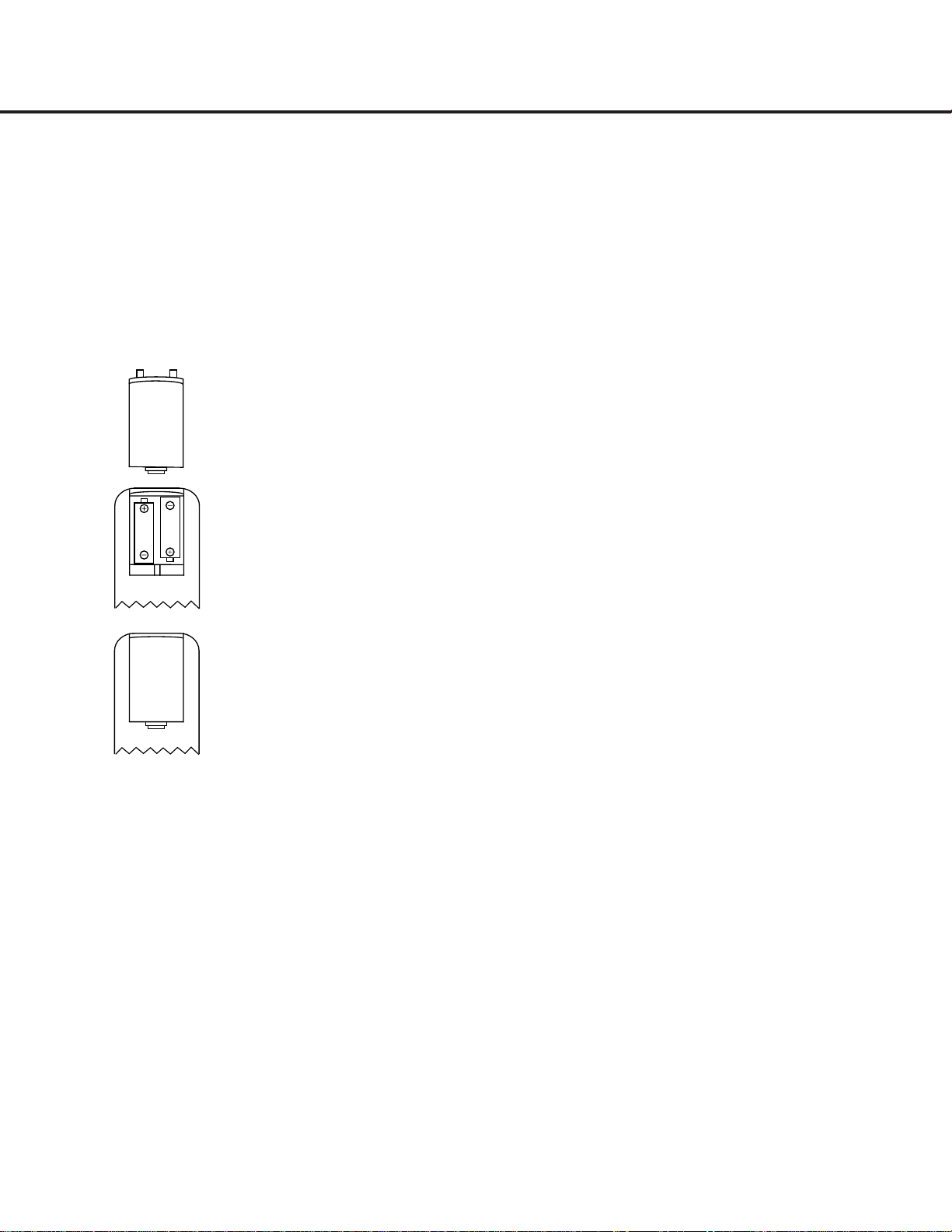
Batteries
Insert the two AA batteries supplied with the CDR 26’s
remote by turning the remote over so that the bottom
of the remote is facing towards you. Gently lift the
plastic tab on the battery cover up and away from
you, and lift the lid off.Insert the batteries in the
remote,being careful to follow the + and – polarity
indications in the bottom of the compartment. Replace
the cover by first seating the two small tabs into the
mating holes at the top of the remote,and then gently
push the cover down until the latch snaps into place
with an audible click.
NOTE: When replacing batteries,it is always a good
idea to replace both at the same time.When the
remote will not be used for an extended period of
time,it is also a good idea to remove the batteries
to avoid the possibility of damage due to corrosion.
Batteries contain chemical substances and we
recommend that you dispose of them properly and
in compliance with any local regulations.
IR Remote Connections
If the CDR 26 is installed behind a cabinet or other
obstruction that may block the path between the front-
panel
Remote Sensor ˆ and the location where
you will use the remote,an optional external IR sensor
may be used. Connect the sensor to the
Remote IR
In Jack
¶ on the rear panel. This jack may also be
connected to the IR Output jack of another compatible
Harman Kardon component or a compatible IR system
remote product.
You may also use the IR sensor in the CDR 26 to
send commands to other compatible remote products.
Connect the
Remote IR Out Jack • to the input of
the other product or system.
Power Connections
Connect the AC Power Cord ª to an AC power
source.The CDR 26 uses sensitive, high-performance
computer-grade CD drives,and to protect them we
recommend that you consider the use of a surge
protector,just as you would for a computer.
If the rear-panel AC outlet on a receiver or other prod-
uct is used, make certain that the total power of all
products connected does not exceed the maximum
rated output of the product containing the outlets.
If the CDR 26 is connected to a switched outlet,
remember to turn on the outlet or product controlling
it in order for the CDR 26 to operate.
15

TROUBLESHOOTING GUIDE AND ERROR MESSAGES 23
TROUBLESHOOTING GUIDE AND ERROR MESSAGES
TROUBLESHOOTING GUIDE
SYMPTOM POSSIBLE CAUSE SOLUTION
Unit does not operate when Standby switch • No AC power • Make certain AC power cord is plugged into a live outlet
or remote Power-On is pressed • Check to see whether AC outlet is switch-controlled
• Main Power Switch is off • Turn on Main Power
Remote does not function • Wrong deck selected • Press the
CDP Button d to control the Play Deck 3;
press the
CDR Button ` to control the Record Deck %
• Dead batteries • Replace both batteries
• Sensor blocked • Remove obstructions from front panel or
connect a remote sensor to the Remote-In Jack
Disc does not erase • CD-R disc in use • CD-R discs do not erase; only CD-RW discs may be erased
Recorded CD-R disc does not play in • CD-R disc not finalized • Finalize the CD-R disc in the CDR 26’s record deck
another CD player or
DISC ERROR (see page 21)
message appears in play deck
Recording suddenly stops • Input source stopped or paused • Recordings will stop when the input source is paused
for more than three seconds for digital recordings
and 10 seconds for analog recordings
ERROR MESSAGES
MESSAGE EXPLANATION AND PROBABLE CAUSE SOLUTION
CHECK DISC • A record-related button has been pressed when a • Unfinalize the disc to add tracks to a CD-RW disc
finalized disc is in the
Record Deck % • Replace the disc with a blank CD-R or CD-RW disc
• A record-related button has been pressed when a • Replace the disc with a blank CD-R or CD-RW disc
standard CD is in the Record Deck %
DATA DISC • A non-audio CD-ROM or a CD Video disc has been • Only CD Audio and DTS
®
discs will play in the CDR 26;
placed in the machine replace the disc
DISC ERROR • An unfinalized disc has been placed in the Play Deck 3 • Finalize the disc (see page 21)
• ADVD has been placed in the unit • Replace the disc; the CDR 26 does not play or dub DVDs
DISC FULL • There are only four seconds of record time remaining • Use another blank CD-R or CD-RW disc
on the disc being recorded • Erase one or more tracks on a CD-RW disc
ERROR • The disc is not seated properly • Open the drawer and check to see that the disc is properly seated
• There is a problem with the disc • Try another disc
FAILED • A dub has not been completed properly • Check the play disc
• Repeat the dub process
FULL • More than 99 tracks have been recorded • The CDR 26 does not record more than 99 tracks on a disc
NO AUDIO • Arecord-related button has been pressed when • Replace the disc with a blank CD-R or CD-RW Audio disc
a non-audio disc is in the Record Deck %
SVC-1 • There is an internal problem with the CDR 26 • Contact an authorized Harman Kardon service center
16
17
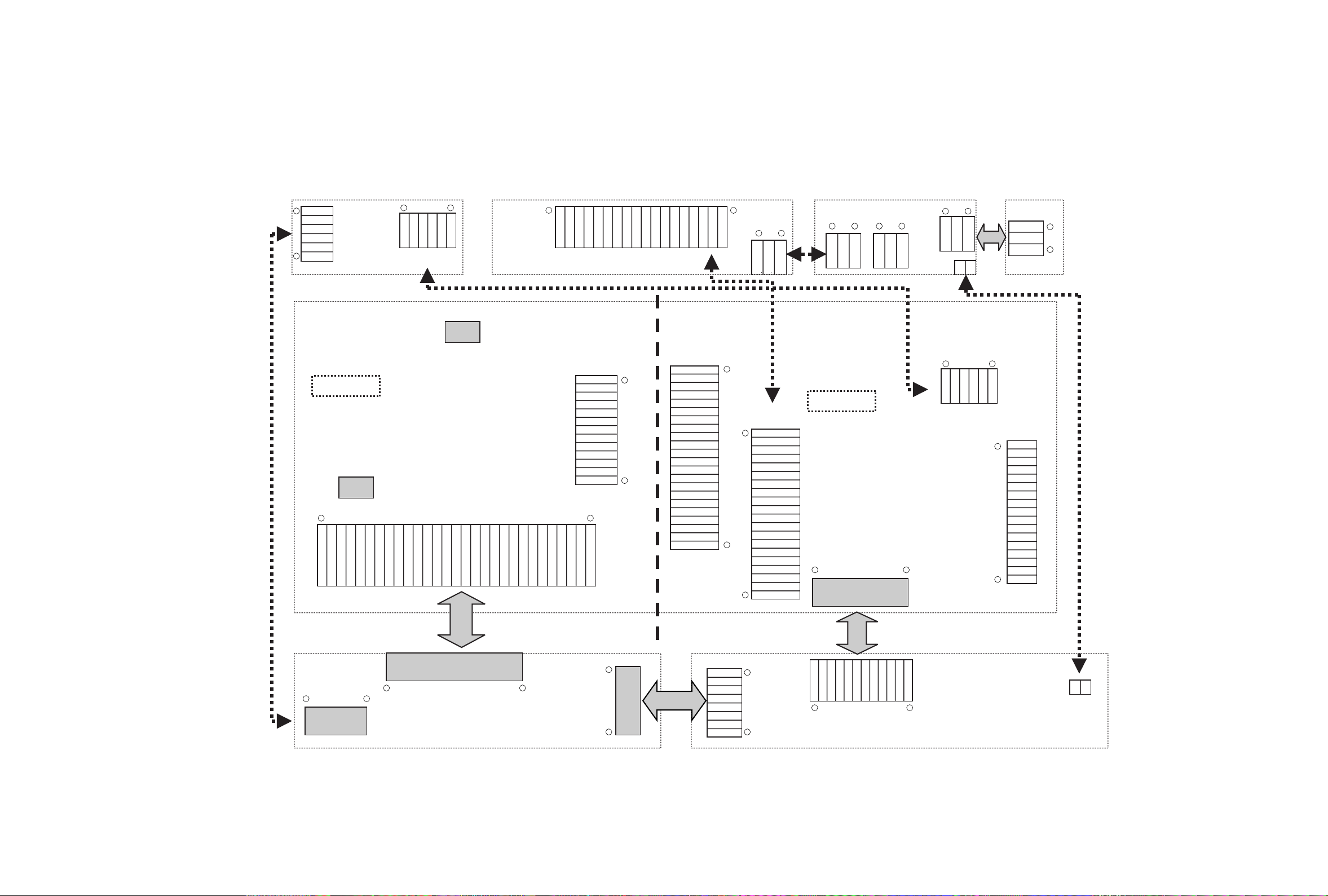
OVERALL WIRING DIAGRAM 1
GREEN
GND
RED
RED
GND
GREEN
CN805
CN807
CN801
PN809
PN8512 PN8511
PN8802
CN809
SW201
LOAD_SW
Download
Download
PN304
PN501
PN403
PN401
PN503
PN405
PN406
PN102
CN103
CN701
CN702
PN703
PN101
CN8901
PN303
CD-RW PART
CD-P PART
Dig. Jack B/D
Front Board H/P Jack B/D
Power LED B/D
I/O Board
Power Board
MAIN Board
ROU`T
GND
RIN
LIN
GND
LOUT
6
6 1
1
NC
GND
DIG-IN
VCC
GND
OPT-IN
GND
DIG_IN
GND
GND
AD_DATA
AD_BCK
AD_LRCK
GND
AD_MCLK
GND
DA_CLK
DA_DATA
DA_LRCK
GND
DA_MCLK
A_DATA_ZERO
F_DOUT
CS_DAC
SCK_DAC
DST_DAC
GND
DUB_SEL
PWR_MUTE
EXT_RMC
DAC_RST
LEVEL_SEL
LEVEL_IN
GND
GND
W
V
U
H+
HU+
HU-
HV+
HV-
HW+
HW-
H-
GND
SLDIN_SW1
13
22
22
1
1
1
30
30
6 1
1
8
1
1
8
12 1
1
12V
GND
5.2VA
GND(A)
8VA
-8VA
GND(D)
5VD
-21VA
-26VA
-30VA
D_GND
5VU
A_GND
5VD
D_GND
5.2VA
3.3V
PWR_CTRL
8VA
12
17
1
16
1 3
3 13 1
3
1 20
1
3
1
1
F+
T+
T-
F-
GND
VC
VCC
F
E
C
B
D
A
LD
WD
WR
RF
NC
GND
DIG-IN
VCC
GND
OPT-IN
HP_R
GND
GP_L
RED
GND
GREEN
RED
GND
GREEN
GND
GND
KEY_IN1
RESET
FLD_CLK
FLD_RXD
KEY_IN0
RMC_IN
FLD_CS
5VU
GND
GND
F-
F-
-34V
-34V
F+
F+
U
W
V
SLD_INSW
GND
HV-
H-
H+
HU+
HU-
HW+
HW-
HV+
GND
B
/B
/A
A
OPCL_SW2
OPCL_SW1
L+
L-
GND
GND
KEY_IN1
RESET
FLD_CLK
FLD_RXD
KEY_IN0
GND
KEY_IN3
WMC_IN
FLD_CS
5VU
GND
GND
F1
F1
-34V
-34V
F2
F2
18
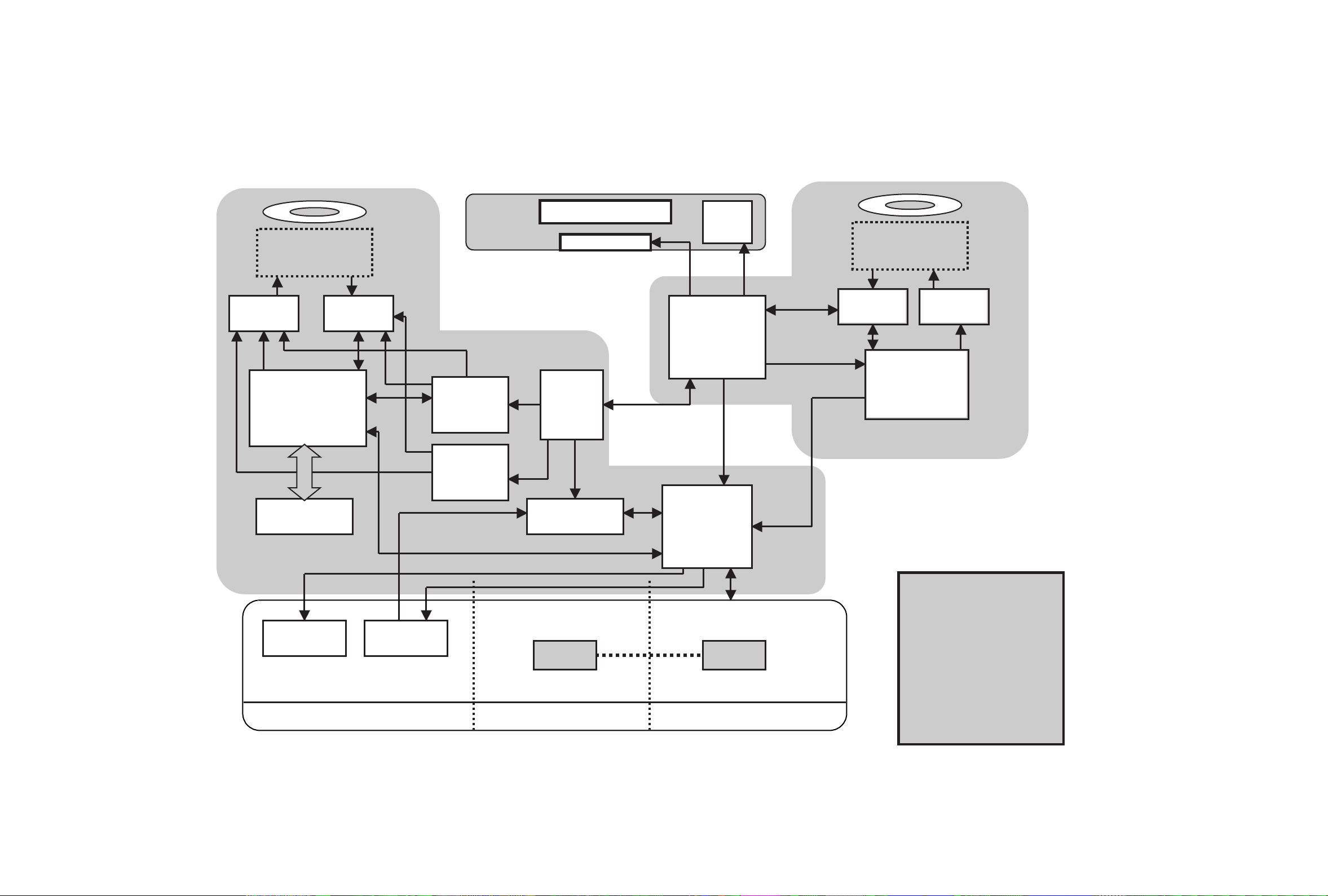
OVERALL WIRING DIAGRAM 2
Power
Servo DSP
+Decoder
FPGA
DAC ADC
U-COM
For
CD-RW
U-COM
For
CD-P
Servo DSP
+ENC/DEC
DRAM
Drive RF Amp.
DriveRF Amp.
SRC
FLD
FLD Driver
Key
Expander
(CPLD)
ANALOG
OPTICAL COAXIAL
MD
MD
S/W S/W
Expander
CD-RW
CD-P
I/O
AK4382
AKM
AK5380
AKM

19
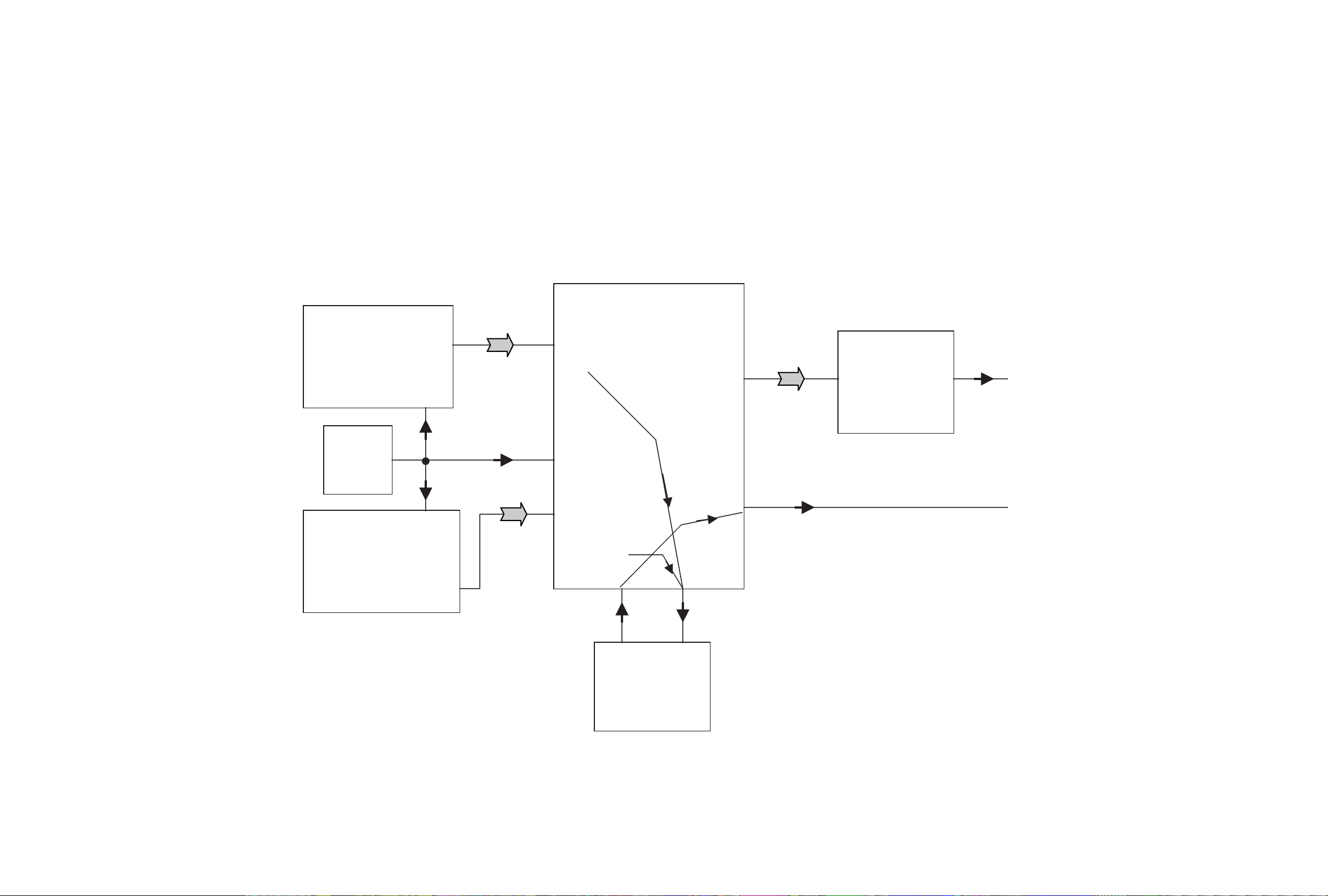
BLOCK DIAGRAM
1. I/O Block Diagram
AK4382
DAC
AK5380
ADC
Relay
74H04
Buffer
74H04
Buffer
H/P OUT
Buffer
RMCN
Jack
Tr.
Analog R Out
Analog L Out
Analog R In
Analog L In
Coaxial Out
Coaxial In
Optical Out
Optical In
Front REC Vol.
DA_MCK
DA_BCK
DA_LRCK
DA_DATA
AD_MCK
AD_BCK
AD_LRCK
AD_DATA
DIG_IN
F-Out(digital out)
LEVEL IN
LEVEL SEL
EXT RMC
OPTICAL IN
C
D
R
W
20
2. CD-P Block Diagram
PLAY Path
CDP
CDRW
33M
LRCK 47
DATA 48
BCK 49
D.OUT 70
IC402
LRCK 144
DATA 143
BCK 145
D.OUT 146
IC201
33M
149
33M
IC408
6
33M
13
63 LRCK
65 DATA
64 LRCK
36 D.OUT
28 LRCK
29 DATA
27 BCK
32 D.OUT
LRCK 42
DATA 49
BCK 51
DA MCLK 55
4 LRCK
3 DATA
2 BCK
1 MCLK
IC510
IC7V2
DAC
50 MLCK
SRC
IC502
4
TXP
26
RXP
D.OUT
D.OUT 41
RXP
66
TXP
66

21
3. CD-R Block Diagram
REC Path
CDRW
/HD [0]
/HD[15]
IC201
LRCK 40
BCK 39
DA MCLK 53
AD DATA 43
10 LRCK
12 BCK
11MCLK
9 AD DATA
IC510
IC7V2
DAC
SRC
IC502
26
RXP
Rear
D.IN(Coaxial)
D.IN 36
RXP
66
2 /HD [0]
19 /HD[15]
Rear
Optical IN
Opt IN 37
Front
D.IN
(Coaxial)
Front
Optical IN
IC411IC406
F.D.IN 37
26
S/W OUT
13
3
10
6
3
5
Buffer
46 LRCK
44 DATA
45 BCK
LRCK 17
BCK 16
DATA 18
LRCK 12
BCK 13
DATA 14
69 LRCK
70 BCK
68 DATA
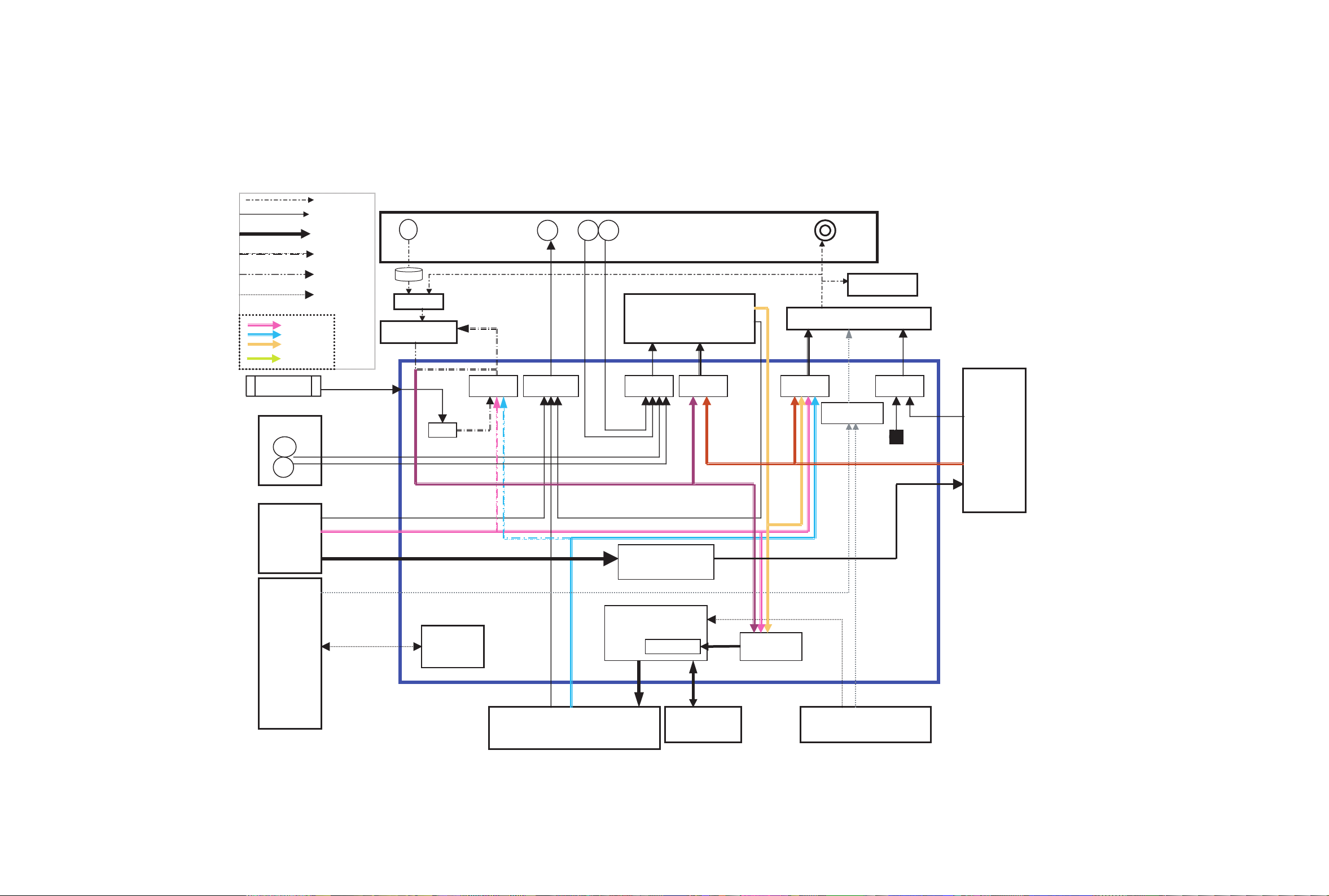
22
4. IC510 Asic Block Diagram
OAK 9790
Sony3030
CDRW 3062 u-com
SRC (CS8420)
Orange
(XCS10TQ144)
CoaxCoax Opt
Din_src
Rec. formatter
Coax
Front
Da_srcDout_src
Rec_src
Src_src
Ain
A/D (AK5351)
D/A (AK4393)
Rear
Vol
AES3
ATAPI
Analog
CDP
3062 u-com
32K SDRAM
HOST I/F
AD_clk_src
Cdp_cdr_src
33.8688MHz
Lrck/clk
Audio Data
Control Signal
Rec Start
U-com I/F
CDP I2S
CDRW I2S
SRC I2S
DA_CTRL
Level Meter
Relay
Opt
Div
MAS3507D
I2s_mode
Da_clk_src
11MHz.
CDP ATAPI
Process
Block Diagram
of IC510
23
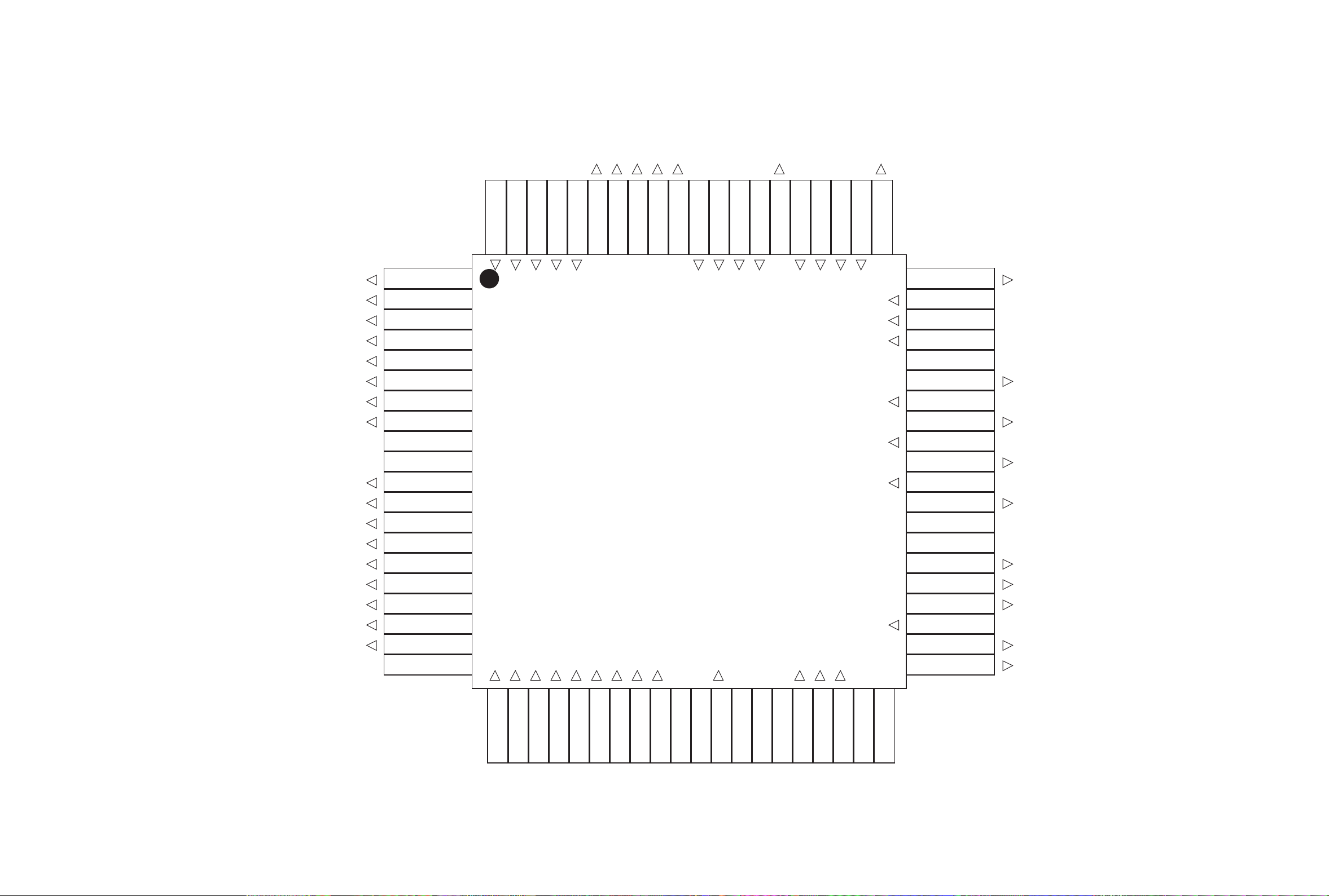
mas_da_clk
dub_start
da_rdata
da_rclk
da_rcs
test_lr_ch
cdr_rst
dac_rst
test_dubsel
cxd_mute
s_d_clk
s_d_lrck
s_d_data
fpga_as
src_rxp
rw_lrck
rw_data
test_omck
s_d_txp
rw_clk
diowb
atapi<15>
atapi<0>
atapi<14>
atapi<1>
atapi<13>
atapi<2>
atapi<12>
<GND>
<VDD>
atapi<3>
atapi<11>
atapi<4>
atapi<10>
atapi<5>
atapi<9>
atapi<6>
atapi<8>
atapi<7>
<GND>
cs1_b
test_mode
mclk_in
reset
rw_dout
D_out
da_lrck1
da_clk
da_data
dac_mclk
<VDD>
<GND>
src_lrck
src_clk
src_data
ad_data
ad_mclk
F_opt_in
test_in
<GND>
fpgacs_1
sclk_1
sdatao_1
da_pcs
da_pclk
da_pdata
p_clk
p_lrck
p_data
p_dout
sdt_dac
sck_dac
cs_dac
<GND>
<VDD>
F_coax_in
ad_lrck
ad_clk
R_coax_in
R_opt_in
5
10
15
20
25 30 35
40
45
50
55
60
65
70
75
80
5. IC501 Pin Map Block Diagram
24
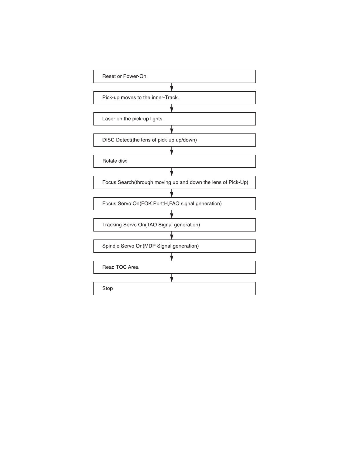
TROUBLESHOOTING GUIDE
1. Initial Lead-in Operation
2. Trouble List(Circuit)
(In the Initial Lead-in Operation Mode)
A. Pick-Up doesn’t move to the inner-track.
B. Pick-Up lens doesn’t move up and down.
C. Disc doesn’t rotate.
D. The Laser(RED) of Pick-Up doesn’t light.
E. TOC isn’t read.
 Loading...