


harman/kardon DVD 29/230 Service Manual
harman/kardon Service Manual
DVD 29/230
DVD player
CONTENTS
TECHNICAL SPECIFICATIONS |
2 |
EXPLODED VIEW |
9 |
TROUBLESHOOTING GUIDE |
3 |
PARTS LIST |
10 |
FRONT PANEL CONTROLS |
4 |
SEMICONDUCTOR PINOUTS |
24 |
FRONT PANEL DISPLAY |
5 |
WIRING DIAGRAM |
50 |
REAR PANEL CONNECTIONS |
6 |
SCHEMATIC DIAGRAMS |
51 |
SETUP AND CONNECTIONS |
7 |
|
|
Released EU2008 |
harman/kardon, Inc. |
Rev 0, 10/2008 |
|
250 Crossways Park Dr. |
|
|
Woodbury, New York, 11797 |
|
Page 1 of 55

harman/kardon |
DVD 29/230 Service Manual |
Technical Specifications
Applicable Disc: |
Disc formats: 5 inch (12 cm) or 3 inch (8 cm) DVD Video, DVD-Audio, Standard conforming DVD+RW, DVD+R, DVD-R, |
|
|
DVD-RW, DivX, VCD, CD, CD-R, MP3, WMA, JPEG or CD-RW discs, |
|
|
Regio code: DVD Movie disc with Code 2 or 0 only. |
|
|
DVD-Layers: Single Side/Single Layer, Single Side/Dual Layer, Dual Side/Single Layer, Dual Side/Dual Layer |
|
|
Audio formats: DVD-Audio MLP lossless, Linear PCM, MPEG, Windows Media® 9, |
|
|
Dolby Digital or DTS Audio discs |
|
|
Still-image format: JPEG |
|
Video Signal System: |
PAL /NTSC |
|
HDMI™ Output: |
Video: 576p, 720p, 1080i |
|
|
HDMI Version 1.0-compliant |
|
|
HDCP Version 1.1-compliant |
|
Composite Video Output: |
1 Vp-p /75 Ohms, sync negative polarity |
|
S Video Output: |
Y/Luminance: 1 Vp-p /75 Ohms, sync negative polarity |
|
|
C/Chrominance: 0.286 Vp-p |
|
Component Video Output: |
Y: 1 Vp-p /75 Ohms, sync negative polarity |
|
|
Cr: 0.7 Vp-p /75 Ohms |
|
|
Cb: 0.7 Vp-p /75 Ohms |
|
Analog Audio Output: |
2 Vrms max |
|
Frequency Response: |
DVD (Linear PCM): |
2Hz - 22kHz (48kHz sampling) |
|
|
2Hz - 44kHz (96kHz sampling) |
|
CD: |
2Hz - 20kHz |
Signal/Noise Ratio (SNR): |
105 dB (A-weighted) |
|
Dynamic Range: |
DVD: 100dB (18 Bit) / 105dB (20 Bit) |
|
|
CD/DVD: 96dB (16 Bit) |
|
THD/1kHz: |
DVD/CD: 0.0025 % |
|
Wow & Flutter: |
Below Measurable Limits |
|
AC Power: |
100 - 240 V/50 ~ 60 Hz |
|
Power Consumption: |
1 Watts (Standby)/13 Watts (Max) |
|
Dimensions (WxHxD): |
440 x 50 x 285 mm |
|
Weight: |
4.0 kg |
|
ENGLISH
Depth measurement includes knobs and connectors.
Height measurement includes feet and chassis.
All specifications subject to change without notice.
Harman Kardon and Harman International are registered trademarks of Harman International Industries, Incorporated. Manufactured under license from Dolby Laboratories. Dolby, Dolby Digital, ProLogic and the double-D symbol are trademarks of Dolby Laboratories. Confidential.
Unpublished Work. © 1992-1997 Dolby Laboratories, Inc. All rights reserved.
Manufactured under license under U.S. Patent #: 5,451,942 & other U.S. and worldwide patents issued & pending.
DTS and DTS Digital Out are registered trademarks and the DTS logos and Symbol are trademarks of DTS, Inc. © 1996-2007 DTS, Inc. All Rights Reserved. Microsoft, Windows and WMA are either registered trademarks or trademarks of Microsoft Corporation in the United States and/or other countries. HDMI, the HDMI logo and High-Definition Multimedia Interface are trademarks or registered trademarks of HDMI Licensing LLC.
DivX, DivX Certified, and associated logos are trademarks of DivX Networks, Inc and are used under license.
This product incorporates copyright protection technology that is protected by method claims of certain U.S. patents and other intellectual property rights owned by Macrovision Corporation and other rights owners. Use of this copyright protection technology must be authorized by Macrovision Corporation and is intended for home and other limited viewing uses only unless otherwise authorized by Macrovision Corporation. Reverse engineering or diassembly is prohibited.
Page 2 of 55

harman/kardon DVD 29/230 Service Manual
Troubleshooting Guide
TroubleShooting Guide
Symptom |
Possible Cause |
Solution |
|
Unit does not turn on |
• No AC power |
• Check AC power plug and make certain any switched |
|
|
|
|
outlet is turned on. |
|
|
|
|
Disc does not play |
• Disc loaded improperly |
• Load disc label-side up; align the disc with the guides and place |
|
|
|
|
it in its proper position. |
|
|
|
• Incorrect disc type |
|
|
|
• Check to see that disc is CD, CD-R, CD-RW, DivX, VCD, MP3, WMA, |
|
|
|
JPEG, DVD-R, DVD-RW, DVD+R, DVD+RW (standard conforming), |
|
|
|
DVD-Audio or DVD-Video; other types will not play. |
|
|
|
• Invalid Region Code |
|
|
|
• Use Region 2 or Open Region (0) disc only. |
|
|
|
• Rating is above parental preset |
|
|
|
• Enter password to override or change rating settings. |
|
|
|
|
No picture |
• Intermittent connections |
• Check all video connections. |
|
|
|
• Wrong input |
• Check input selection of TV or receiver. |
|
|
• Progressive Scan output selected |
• Use Progressive Scan mode only with compatible TV. If needed, press |
|
|
|
the Progressive Scan/Interlaced Button L to toggle to the |
|
|
|
correct mode. |
|
|
• Video Off feature active |
• Press Video Off Button Q to reactivate video circuitry (see page 23) |
|
|
• HDMI Output is connected to a |
• The HDMI Output may not be used with video displays that are not |
|
|
video display that is not HDCP-compliant |
HDCP-compliant. Unplug the cable and select another audio and video |
|
|
|
connection (see pages 11 through 12). |
|
|
|
|
No sound |
• Intermittent connections |
• Check all audio connections. |
|
|
|
• Incorrect digital audio selection |
• Check digital audio settings. |
|
|
• DVD disc is in fast or slow mode |
• There is no audio playback on DVD discs during fast or slow modes. |
|
|
• Surround receiver not compatible |
• Use analog audio outputs. |
|
|
with 96kHz PCM audio |
• Use 6-Channel Audio Outputs or Analog Audio Outputs . |
|
|
• DVD Audio disc is loaded without |
|
|
|
using analog audio connection |
|
|
|
|
|
Picture is distorted or jumps during |
• MPEG-2 decoding |
• It is a normal artifact of DVD playback for pictures to jump or show |
|
fast forward or reverse play |
|
some distortion during rapid play. |
|
|
|
|
|
Some remote buttons do not operate |
• Function not permitted at this time |
• With most discs, some functions are not permitted at certain |
|
during DVD play; prohibited symbol |
|
times (e.g., Track Skip) or at all (e.g., direct audio track selection). |
|
appears (see below) |
|
|
|
|
|
|
|
The OSD menu is in a foreign language |
• Incorrect OSD language |
• Change the display language selection. |
|
|
|
|
|
The |
symbol appears |
• Requested function not available at |
• Certain functions may be disabled by the DVD itself during |
|
|
this time |
passages of a disc. |
|
|
|
|
Picture is displayed in the |
• Incorrect match of aspect ratio settings |
• Change aspect ratio settings. |
|
wrong aspect ratio |
to disc |
|
|
|
|
|
|
Remote control inoperative |
• Weak batteries |
• Change both batteries. |
|
|
|
• Sensor is blocked |
• Clear path to sensor or use optional outboard remote sensor. |
|
|
|
|
Disc will not copy to VCR |
• Copy protection |
• Many DVDs are encoded with copy protection to prevent |
|
|
|
|
copying to VCR. |
Password not accepted |
• Incorrect password being used or |
|
password has been forgotten |
•Stop play of disc. Press and hold the Clear Button until the display blinks. This resets the password and all settings to their defaults.
Page 3 of 55
harman/kardon |
DVD 29/230 Service Manual |
Front Panel Controls
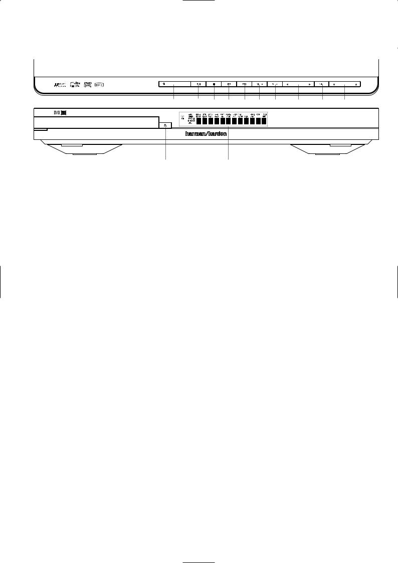
1 |
3 5 6 7 8 4 9 A B |
Main Information Display
1 Power On/Off (Standby)
2 Open/Close
3Play/Pause
Main Information Display: This display delivers messages and status indications to help you operate the DVD player.
1 Power On/Off (Standby): Press the button once to turn the DVD player on, press it again to put the unit in the Standby mode.
2 Open/Close: Press this button to open or close the Disc Tray.
3 Play/Pause: Press to initiate playback or to resume playback after Pause has been pressed. Press this button to momentarily pause playback. To resume playback, press the button again. If a DVD is playing, action will freeze and a still picture will be displayed when the button is pressed.
2 |
|
4 Setup
5 Stop
6 Skip/Search (Previous)
7 Skip/Search (Next)
4 SETUP: Press this button to use the
DVD 29’s on-screen menu system to adjust the player’s configuration settings. Note that the Info Button A must be pressed to access the DVD 29’s Player Information menu to obtain detailed disc information, and to configure the playback mode of the disc.
5 Stop: Press this button once to place the disc in the Resume mode, which means that playback will stop, but as long as the tray is not opened or the disc changed, DVD playback will continue from the same point on the disc when the Play Button is pressed again. Resume will also work if the unit was turned off. To stop a disc and have play start from the beginning, press the button twice.
6 Skip/Search (Previous): Press this button to move backward through the music tracks on a CD disc or the chapters on a DVD disc. Keep the button pressed to search backwards at one of the available speeds.
8 Dimmer
9 Arrows left and right A Enter
B Arrows up and down
7 Skip/Search (Next): Press to move forward through the music tracks on a CD or the chapters on a DVD disc. Keep the button pressed to search forwards at one of the available speeds.
8 Dimmer: Press this button to reduce the brightness of the Information Display by 50% or to turn the display off completely in the following order: FULL BRIGHTNESS HALF BRIGHTNESS OFF FULL BRIGHTNESS.
9 ARROW buttons (M / N ): Use to move the cursor in the OSD.
A ENTER: Press this button to activate a setting or option.
B ARROW buttons (K/L): Use to move the cursor in the OSD.
Page 4 of 55

harman/kardon |
DVD 29/230 Service Manual |
Front Panel Information Display
C |
N LM J KI H G |
O |
A |
B F D E
ADisc Type Indicators
BPlayback-Mode Indicators
CAudio Bitstream Indicators
DChapter/Track Number Indicators
ETime Indicators
A Disc Type Indicators: The CD, DVD, DVDAudio, VCD, MP3, WMA or JPEG indicator will illuminate to show the type of disc currently being played.
BPlayback-Mode Indicators: These indicators light to show the current playback mode:
BLights when a disc is playing in the normal mode
H Lights when the disc is in the Fast Search Forward mode. The on-screen banner display indicates the selected speed (x2, x4, x8, x20, x100).
1 Lights when the disc is paused.
G Lights when the disc is in the Fast Search Reverse mode. The on-screen banner display indicates the selected speed (x2, x4, x8, x20, x100).
CAudio Bitstream Indicators: When a Dolby® Digital, DTS® or linear PCM digital audio signal is present on the disc, one of these indicators will light. DVD-Audio, MP3 and WMA bitstreams will be indicated by the Disc Type Indicator A.
D Chapter/Track Number Indicators: When a DVD disc is playing, these two positions in the display will show the current chapter. When a CD disc is playing they will show the current track number.
FTitle Indicators
GV-OFF Indicator
HRepeat Indicators
IVCD Playback Control Indicator
JRandom Indicator
ETime Indicators: These positions in the indicator will show the running time of a DVD in play. When a CD is playing, these indicators will show the current track time, time remaining in the current track, or the total remaining time on the disc.
NOTE: The Indicators DEFwill also display text messages about the DVD’s status, including LOADING when a disc is loading,
POWER OFF when the unit is turned off, and DISC ERROR when a disc not compatible with the DVD is put into the play position.
FTitle Indicators: These two positions in the display will show the current title number when a DVD disc is playing.
GV-OFF Indicator: This indicator lights when the unit's video output has been turned off by pressing the V-OFF button on the remote control.
H Repeat Indicators: These indicators light when any of the Repeat functions are in use.
KA-B Repeat Indicator
LProgram Indicator
MAngle Indicator
NParental Lock Indicator
OVideo Output Indicators
IVCD Playback Control Indicator: This indicator lights when the playback control function is turned on with VCDs.
J Random Indicator: This indicator lights when the unit is in the Random Play mode.
KA-B Repeat Indicator: This indicator lights when a specific passage for repeat playback has been selected.
L Program Indicator: This indicator lights when the programming functions are in use.
MAngle Indicator: This indicator blinks when alternative viewing angles are available on the DVD currently playing.
NParental Lock Indicator: This indicator lights when the parental-lock system is engaged in order to prevent anyone from changing the rating level without a code.
OVideo Output Indicators: When the DVD 29 is connected to a video display using the HDMI Output , the display sends information to the DVD 29 indicating the highest video resolution it is capable of handling, and the DVD 29 automatically sets the video output to match it. That resolution is displayed here. You may use the HD Mode Selector to
manually select a lower video output resolution.
ENGLISH
Page 5 of 55

harman/kardon |
DVD 29/230 Service Manual |
Rear Panel Connections
|
|
|
|
|
|
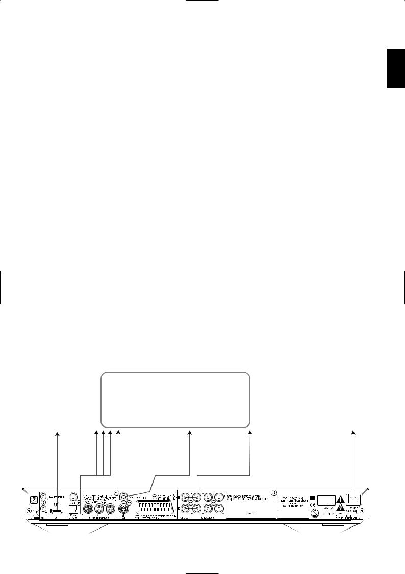
Optical Digital OutputCoaxial Digital OutputAC Power Cord
Composite Video Output
Optical Digital Output: Connect this jack to the optical digital input of an A/V receiver or surround processor for Dolby Digital, DTS or PCM audio playback.
Coaxial Digital Output: Connect this jack to the coaxial digital input of an A/V receiver or surround processor for Dolby Digital, DTS or PCM audio playback.
NOTE: The coaxial digital output should only be connected to a digital input. Even though it is the same RCA-type connector as standard analog audio connections, DO NOT connect it to a conventional analog input jack.
Connect either the Optical Digital Audio Output or the Coaxial Digital Audio Output to a corresponding digital audio input on your receiver or processor, but not both.
AC Power Cord: Connect this plug to an AC outlet. If the outlet is controlled by a switch, make certain that it is in the ON position.
Composite Video Output: Connect this jack to the video input on a television or video projector, or to a video input on an A/V receiver or processor if you are using that type of device for video input switching.
S-Video Output: Connect this jack to the S-Video input on a television or video projector, or to an S-Video input on an A/V receiver or processor if you are using that type of device for S-Video input switching.
Component Video Outputs: These outputs carry the component video signals for connection to display monitors with component video inputs. For standard analog TV's or projectors with inputs marked Y/Pr/Pb or Y/Cr/Cb, connect these outputs to the corresponding inputs. If you have a high-definition television or projector that is compatible with high scan rate progressive video, connect these jacks to the “HD Component” inputs. Note that if you are using a progressive scan display device, then ”Progressive” must be selected in the Video Setup Menu in order to take advantage of the progressive scan circuitry. See page 19 for more information on progressive scan video.
S-Video Output
Component Video Outputs Scart TV Output
Remote Control Output
IMPORTANT: These jacks should NOT be connected to standard composite video inputs.
SCART OUT (TV): If your TV has a SCART socket, you can connect a SCART cable to your TV and to your DVD Player for improved video quality. The SCART cable carries both audio and video. You can select Composite Video or RGB video for that SCART connector’s video output signal.
Remote Control Output: Connect this jack to the infrared (IR) input jack of another compatible Harman Kardon remote controlled product to have the built-in Remote Sensor on the DVD provide IR signals to other compatible products.
Remote Control Input: Connect the output of a remote infrared sensor, or the remote control output of another compatible Harman Kardon product, to this jack. This will enable the remote control to operate even when the front panel Remote Sensor on the DVD is blocked. This jack may also be used with compatible IR remote control-based automation systems.
Analog Audio Output: Connect these jacks to an audio input on an A/V receiver or surround processor for analog audio playback.
HDMI Output: If you have an HDMI-com- patible receiver or video display device, connect this output to an HDMI input on the receiver or video display for the highest-quality uncompressed digital audio and video available. Even if your receiver is not capable of processing audio in the HDMI format, you may still experience the superb reproduction of HDMI video.
If your video display has a DVI input, you may use an optional HDMI-to-DVI cable or adapter for the connection to the display. In all cases, the video display must be HDCP-compliant in order to use the HDMI output. For best results, we do not recommend HDMI connections in excess of ten feet.
Remote Control Input
Analog Audio Output
HDMI Output
6-Channel Audio Outputs
The following audio formats may be output via the HDMI connection:
Audio CD – 2-Channel PCM or 5.1-channel DTS
DVD-Audio – 2-Channel PCM
DVD-Video – Up to 5.1-channel Dolby Digital or DTS
Note: To hear the high-resolution surround sound recorded on DVD-Audio discs, you need to connect the 6-Channel Audio Outputs to the corresponding input jacks on your receiver or processor. These formats are not output digitally.
6-Channel Audio Outputs: Connect these outputs to the matching 6-channel analog audio inputs on your receiver or surround sound processor. This connection is required to listen to the multichannel tracks on DVD-Audio discs. If the disc also contains a linear PCM, Dolby Digital or DTS track, you may listen to it using the HDMI , Optical or Coaxial Dgital Audio Output or the Analog Audio Outputs .
Note: You’ll find more details about all Audio/Video connections under Setup and Connections on the following pages.
Page 6 of 55
harman/kardon |
DVD 29/230 Service Manual |
Setup and Connections
Before connecting your DVD 29, please:
■Ensure that the power switch of this unit and other equipment to be connected is set to off before commencing connection.
■Do not block ventilation holes of any of the equipment and arrange them so that air can circulate freely.
■Read through the instructions before connecting other equipment.
■Ensure that you observe the color coding when connecting audio and video cables.
For the best quality, if your receiver or processor and/or video display are HDMI-capable, we recommend using the HDMI output. With a single cable connection between components, HDMI is able to deliver uncompressed high-definition digital video and digital audio programming.
Note: If your video display has a DVI input, you may use an optional HDMI-to-DVI cable or adapter for the connection to the display. In all cases, the video display must be HDCP-compli- ant in order to use the HDMI output.
If your equipment is not HDMI-ready, we recommend the use of component video for higher quality pictures.
If you are using a television or video display that is compatible with high-resolution 576P video signals, make sure to use the input jacks on the video display marked “HD Component,” if available. Also, make sure to configure the display’s input settings for use with “576P” video signals. You will also need to change the scan type in the DVD 29’s Video Setup menu from “Interlaced” to “Progressive.” See page 19.
The Video output (yellow) combines the complete video signal (composite) and sends it to the TV (or to the AV Receiver) by one line only. Use the Video output, when your TV set is equipped with a Video input jack only.
The S (separate) video output connector separates the color (C) and luminance (Y) signals
before transmitting them to the TV set in order to achieve a sharper picture. Use the S-video cable when connecting the player to a TV equipped with an S-video inputfor improved picture clarity. Never connect both outputs, Video and S-Video, to your TV or AV Receiver, only one of them.
Most European TV´s are equipped with SCART connectors rather than with a normal video input (yellow cinch). In that case the SCART connection should be used, providing the audio signal too. Separate analog audio connections to TV are needed only if your TV is connected to the video or S-video output.
You may also use the standard S-video or composite video connection if your TV does not have component video inputs. The component and S-video outputs are not available simultaneously.
•Modern audio/video receivers are capable of connection to several video source devices, such as the DVD 29 and a VCR, cable television set-top box, HDTV tuner or other device. The receiver is equipped with video monitor outputs for connection to your television, projector or plasma display. As you select any input source device, the receiver selects the correct video input and routes it to the correct video monitor output to your television. It is recommended that you connect one
of the video outputs from the DVD 29 to the corresponding input on your receiver to simplify operation of your home entertainment system. Refer to the owner’s guide for your receiver for more information.
•If your receiver is capable of multiroom operation, it is recommended that you connect both the component (or HDMI) and composite video outputs of the DVD 29 to the receiver. This enables the highest-quality picture (component video) for viewing in the main listening room, while enabling the multiroom system, if it is video-capable, to distribute the composite video signal to the remote zone. Consult the owner’s guide for your receiver to determine whether it has video multiroom capability.
Connecting to a TV Only
When using the DVD 29 with a television but no audio receiver or processor, connect it as follows. Make the Analog Audio Connection Aand one of the Video Connections (Composite Video B, S-Video C, Component Video
D). If your television or video display is HDMIcapable, you only need to make the HDMI E connection, as it handles both audio and video. Remember to plug in the power cord.
ENGLISH
TV
|
To Y (green)/ |
|
|
|
|
|
|
|
|
|
|
|
|
|
|
|
||
|
Pb (blue)/ |
|
S |
|
|
|
|
|
|
|
|
|
|
|
|
|
||
|
Pr (red) |
|
|
|
|
|
|
|
|
|
|
|
|
|
|
|||
To HDMI |
component |
|
|
|
|
|
|
|
|
|
|
|
To power outlet |
|||||
or DVI |
video |
|
|
|
|
|
|
|
|
|
|
|
||||||
port on TV |
connectors |
|
|
|
|
|
|
|
|
|
|
|
(AC 230V/50Hz) |
|||||
E |
|
D |
C |
B |
A |
|||||||||||||
|
|
|
|
|
|
|
|
|
|
|
|
|
|
|
|
|
|
|
|
|
|
|
|
|
|
|
|
|
|
|
|
|
|
|
|
|
|
|
|
|
|
|
|
|
|
|
|
|
|
|
|
|
|
|
|
|
|
|
|
|
|
|
|
|
|
|
|
|
|
|
|
|
|
|
|
|
|
|
|
|
|
|
|
|
|
|
|
|
|
|
|
|
|
|
|
|
|
|
|
|
|
|
|
|
|
|
|
|
|
|
|
|
|
|
|
|
|
|
|
|
|
|
|
|
|
|
|
|
|
|
|
|
Page 7 of 55
harman/kardon |
DVD 29/230 Service Manual |
Setup and Connections
Connecting to a Receiver/Amplifier With a Dolby Digital or DTS Decoder
One of the major advantages of the DVD format is its ability to use a variety of digital audio formats for the ultimate in sonic performance.
However, in order to enjoy the benefits of digital audio, you must use a receiver or processor that has digital audio decoding capabilities and make an optical or coaxial digital audio connection between the DVD 29 and your home theater system. This simple connection is made as shown below with an optional coax or optical cable. Only one of these connections is required, and both should not be made at the same time.
In order to take advantage of the high-resolution DVD-Audio output of the DVD 29, you must connect the 6-Channel Audio Outputs to the matching 6-channel inputs on your receiver or processor.
NOTES FOR ANALOG AUDIO:
•If you wish to use the DVD 29 as the input for a multiroom system, the Analog Audio Outputs should be connected to the standard analog left/right DVD or CD inputs on your digital receiver or processor.
•The connection from the Analog Audio Outputs to the TV is optional.
•When the audio signal is to be fed to an analog receiver rather than to the TV, connect the Analog Audio Outputs to any analog audio inputs on your receiver or processor.
•The analog audio connection should also be made if you wish to play high-resolution 96kHz PCM audio discs where your receiver does not support 96kHz processing.
NOTES ON VIDEO:
■Note: With multiple video sources, your Audio/Video device can be used for selecting the video signal and routing it to the TV. Connect the video or S-video output of the DVD player (whatever is provided with your device) to the video or S-video input on your device and the video/S-video output of this device to your TV. For more details, see the manual of your Audio/Video amplifier/receiver.
■Note for Analog Audio: The connection from Audio Out to the TV is optional only. Normally you´ll hear the sound from your AV-system´s speakers, so the TV volume should be completely turned down. If you plan to use your DVD player also without having to turn on your complete system, this connection must exist, then you can turn up the TV´s volume as needed.
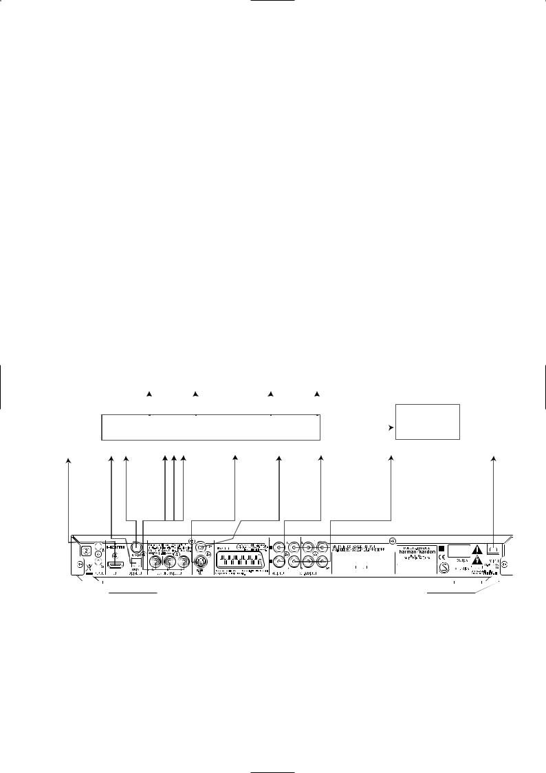
Connecting to a Receiver
When using the DVD 29 with an audio/video receiver or processor, connect it as follows. First, make one of the video connections (Composite Video C, S-Video D, Component Video E or HDMI H) to the video input jacks on the A/V receiver, and then connect the receiver’s video monitor output to the TV. In addition, to benefit from the high-resolution surround sound formats recorded on DVD-Audio discs, which are not output via the HDMI connection, you will need to make the 6-Channel Audio Connection Ato your receiver or processor.
Second, if your receiver or processor is not HDMIcapable, make either the Optical Digital Audio Connection Gor the Coaxial Digital Audio Connection F, to the receiver or processor.
IMPORTANT NOTE: Make certain that any device being connected, including the DVD 29, your receiver or processor and your TV or video display, is turned off whenever you make connections between products.
|
Front Speakers |
|
Center |
|
Surround Speakers |
|
Subwoofer |
|
|
HDMI, DVI, Component, |
||||||||||||||
|
|
|
|
|
||||||||||||||||||||
|
|
|
|
|
|
S-video and/or |
|
|
|
|
|
|
||||||||||||
|
(Left/Right) |
|
Speaker |
|
(Left/Right) |
|
|
|
|
|
|
|
|
|
|
|||||||||
|
|
|
|
|
|
|
Composite video |
|
|
|
|
|
|
|||||||||||
|
|
|
|
|
|
|
|
|
|
|
|
|
|
TV |
||||||||||
|
Dolby Digital/DTS A/V Receiver or Processor |
|
|
monitor outputs |
|
|
||||||||||||||||||
|
|
|
|
|
|
|
|
|
|
|
|
|
|
|
|
|||||||||
|
|
|
coaxial |
To |
|
|
|
|
|
|
To |
|
|
To 6-channel |
||||||||||
To |
optical |
|
|
|
|
|
|
|
|
|
|
|
|
|
|
|
|
|
analog audio |
|||||
HDMI |
digital |
digital |
Pr |
|
|
|
|
|
|
|
|
|
|
|
|
|
|
|
inputs on |
|||||
or DVI |
audio |
|
|
|
|
|
|
|
|
|
|
on |
|
|
receiver |
|||||||||
port |
input |
connectors |
|
|
|
|
|
|
|
or |
|
|
To power outlet |
|||||||||||
|
|
|
|
|
|
|
|
|
|
|
|
|
|
|
|
|
|
|||||||
|
|
|
|
|
|
|
|
|
|
|
|
|
|
|
|
|
|
(AC 230V/50Hz) |
||||||
|
|
|
|
|
|
|
|
|
|
|
|
|
|
|
|
|
|
|
|
|
||||
|
G |
|
E |
|
|
|
|
|
|
|
|
|
|
|
|
|
|
|
|
|
|
|
|
|
|
|
|
|
|
|
|
|
|
|
|
|
|
|
|
|
|
|
|
|
|
|
|
|
|
|
|
|
|
|
|
|
|
|
|
|
|
|
|
|
|
|
|
|
|
|
|
|
|
|
|
|
|
|
|
|
|
|
|
|
|
|
|
|
|
|
|
|
|
|
|
|
|
|
|
|
|
|
|
|
|
|
|
|
|
|
|
|
|
|
|
|
|
|
|
|
|
|
|
|
|
|
|
|
|
|
|
|
|
|
|
|
|
|
|
|
|
|
|
|
|
|
|
|
|
|
|
|
|
|
|
|
|
|
|
|
|
|
|
|
|
|
|
|
|
|
|
|
|
|
|
|
|
|
|
|
|
|
|
|
|
|
|
|
|
|
|
|
|
|
|
|
|
|
|
Important Notes on SCART and RGB format:
■Your DVD is equipped with a SCART connector for direct connection to the TV.
■The SCART connector provides the video signal as well as audio (stereo L/R) signals.
■The SCART connector for the TV provides the composite video signal or the direct RGB signal, delivering the best video performance possible, selectable in the Setup menu.
To view RGB video on your TV, the RGB compatible SCART connector on the TV must be used and the DVD´s TV SCART connector must be set to ”RGB”.
Note that with RGB video the color intensity cannot be adjusted with most TVs.
■When the RGB video signal is used, DVD´s recorded with the NTSC format (with regional code 0 or 2) can be viewed even on nonNTSC compatible TVs.
Page 8 of 55

harman/kardon |
DVD 29/230 Service Manual |
Page 9 of 55

harman/kardon |
DVD 29/230 Service Manual |
DVD 29/230 ELECTRICAL PARTS LIST
POS |
PART NUMBER |
PART NAME |
COMMENTS |
|
|
CHE154 |
CLAMPER , ARM |
|
|
|
CPS1A765 |
PAD , CENTER |
DMC250 |
|
|
CPS2A793 |
PAD , SNOW L |
|
|
|
CPS2A794 |
PAD, SNOW R |
|
|
|
CQXDVD29/230 |
INSTRUCTION MANUAL ASS'Y |
|
|
|
CARTDVD29/230 |
REMOCON TRANSMITTER ASS'Y |
|
|
|
CJS0I006Z |
CABLE, S-VHS(1.5M) |
Y, C |
|
|
CJS4S004Z |
CORD , PIN(3P,W/R/Y) |
|
|
|
CJS8T001Z |
CABLE, HDMI(2M) |
CBADV-005-2 |
|
|
CJS9D002Z |
CORD , JACK(MONO) 1200MM |
|
|
|
CQX1A1294Y |
MANUAL , INSTRUCTION DVD29 |
|
|
|
CGR1A411ZA |
DVD DOOR ASS'Y(DMC250) |
DMC250 |
|
|
CGR1A410 |
ORNAMENT , DOOR |
|
|
|
CGR1A411A25 |
DOOR , DVD |
|
|
|
CGWDVD29/230 |
FRONT PANEL ASS'Y |
|
|
|
CBT2A1029TA |
DVD29/230 FUNCTION KNOB ASS'Y |
|
|
|
CBT2A1029MMTB24 |
KNOB , FUNCTION DVD29 |
|
|
|
CMH2A280 |
HOLDER , KNOB |
|
|
|
CGB1A158Y |
BADGE , FRONT HARMAN/KARDON |
|
|
|
CGB1A187Y |
BADGE , DVD29 |
|
|
|
CGL1A266Y |
INDICATOR , POWER DVD29 |
|
|
|
CGW3A428TA |
FRONT SUB ASS'Y |
|
|
|
CBT1A1030MMYB17 |
KNOB , OPEN DVD29/230 |
|
|
|
CGU2A412A25Z |
WINDOW , FIP DVD29/230 |
|
|
|
CGW3A428R4XB24 |
PANEL , FRONT DVD29/230 |
|
|
|
CGX2A395C66 |
SHEET , AL FRONT DVD49/230 |
|
|
|
CHG1A305 |
CUSHION , SUPPORT |
|
|
|
CMC1A341 |
PLATE , EARTH DMC250 |
|
|
|
CMD1A655 |
FRAME , FRONT |
|
|
|
CMD2A682 |
BRACKET , HOLDER |
|
|
|
CMZ1A118Z |
FILTER , FIP |
|
|
|
CTB3+10JR |
SCREW |
|
|
|
CTB3+8JR |
SCREW |
|
|
|
CTS3+8JFZR |
SCREW |
|
|
|
CWC4F2A07A080B |
CABLE , CARD(7P, 80mm, B TYPE) |
|
|
|
CWC4F2A15A300B |
CABLE, CARD(15P, 300mm, B TYPE) |
|
|
|
C8AAK81 |
BOND , LOCK |
|
|
|
CKC1A182S60 |
CABINET , TOP DVD29 |
|
|
|
CMX1A180Z |
INSULATOR |
|
|
|
CTB3+8JFZR |
SCREW |
|
|
|
CTS3+8JFZR |
SCREW |
|
|
|
CUADVD29/230 |
BOTTOM CHASSIS ASS'Y |
|
|
|
CADDVD29/230ZA |
DVD MECHANISM ASS'Y |
|
|
|
CADSDL003YA |
LOADER ASS'Y |
|
|
|
CMH1A250 |
GUIDE, CABLE |
|
|
|
CWB1B905250EE |
WIRE ASS'Y(5PIN, 250mm) |
12PIN, 250MM, AWG#26 |
|
|
CWB5A906250SE |
WIRE ASS'Y(6PIN, 250mm) |
12PIN, 240MM, AWG#28 |
|
|
CWC4G2A24G400B |
CABLE , CARD(24P, 400mm, B TYPE) |
|
|
|
CHD1A055R |
SCREW , SPECIAL |
|
|
|
CHG1A373 |
CUSHION , FOOT AVR350 |
|
|
|
CJA2B043ZA |
CORD , POWER(EUR) |
QDR-7100CC |
|
|
CKF11A303VK1 |
PANEL , REAR DVD29/230 |
|
|
|
CKL1A098 |
FOOT , L |
|
|
|
CKL1A099 |
FOOT , R |
|
|
|
CMX2A228 |
INSULATOR , SMPS DVD29 |
|
|
|
COP12017B |
DVD29/230 MAIN PCB ASS'Y |
|
|
CN11 |
CJP24GA195ZM |
SMT FFC/FPC WAFER(0.5MM PITCH) |
52559-2472 (PB FREE) |
|
C100 |
CCUS1H104KC |
CAP , CHIP |
0.1UF 50V K |
|
C101 |
CCUS1H104KC |
CAP , CHIP |
0.1UF 50V K |
|
C102 |
CCUS1H104KC |
CAP , CHIP |
0.1UF 50V K |
|
C103 |
CCUS1H104KC |
CAP , CHIP |
0.1UF 50V K |
|
C104 |
CCUS1H104KC |
CAP , CHIP |
0.1UF 50V K |
|
C106 |
CCUS1H104KC |
CAP , CHIP |
0.1UF 50V K |
|
C107 |
CCUS1H104KC |
CAP , CHIP |
0.1UF 50V K |
|
C110 |
CCUS1H104KC |
CAP , CHIP |
0.1UF 50V K |
|
C112 |
CCUS1H104KC |
CAP , CHIP |
0.1UF 50V K |
|
C113 |
CCUS1H104KC |
CAP , CHIP |
0.1UF 50V K |
|
Page 10 of 55
harman/kardon |
DVD 29/230 Service Manual |
POS |
PART NUMBER |
PART NAME |
COMMENTS |
C115 |
CCUS1H104KC |
CAP , CHIP |
0.1UF 50V K |
C117 |
CCUS1H104KC |
CAP , CHIP |
0.1UF 50V K |
C120 |
CCUS1H104KC |
CAP , CHIP |
0.1UF 50V K |
C122 |
CCUS1H104KC |
CAP , CHIP |
0.1UF 50V K |
C124 |
CCUS1H104KC |
CAP , CHIP |
0.1UF 50V K |
C126 |
CCUS1H104KC |
CAP , CHIP |
0.1UF 50V K |
C127 |
CCUS1H104KC |
CAP , CHIP |
0.1UF 50V K |
C129 |
CCUS1H104KC |
CAP , CHIP |
0.1UF 50V K |
C146 |
CCUS1H104KC |
CAP , CHIP |
0.1UF 50V K |
C156 |
CCUS1H180JA |
CAP , CHIP(18PF/50V) |
18PF 50V J |
C157 |
CCUS1H330JA |
CAP , CHIP |
33PF 50V J |
C158 |
CCUS1H330JA |
CAP , CHIP |
33PF 50V J |
C159 |
CCUS1H562KC |
CAP , CHIP CERAMIC(1608, 5600p) |
5600PF 50V K |
C160 |
CCUS1H562KC |
CAP , CHIP CERAMIC(1608, 5600p) |
5600PF 50V K |
C161 |
CCUS1H562KC |
CAP , CHIP CERAMIC(1608, 5600p) |
5600PF 50V K |
C163 |
CCUS1H471JA |
CAP , CHIP |
470PF 50V J |
C164 |
CCUS1H104KC |
CAP , CHIP |
0.1UF 50V K |
C165 |
CCUS1H104KC |
CAP , CHIP |
0.1UF 50V K |
C166 |
CCUS1H102KC |
CAP , CHIP |
1000PF 50V K |
C167 |
CCUS1H102KC |
CAP , CHIP |
1000PF 50V K |
C168 |
CCUS1H102KC |
CAP , CHIP |
1000PF 50V K |
C169 |
CCUS1H102KC |
CAP , CHIP |
1000PF 50V K |
C170 |
CCUS1H102KC |
CAP , CHIP |
1000PF 50V K |
C172 |
CCUS1H102KC |
CAP , CHIP |
1000PF 50V K |
C173 |
CCUS1H102KC |
CAP , CHIP |
1000PF 50V K |
C174 |
CCUS1H333KC |
CAP , CHIP |
0.033UF 50V K |
C175 |
CCUS1H104KC |
CAP , CHIP |
0.1UF 50V K |
C176 |
CCUS1H102KC |
CAP , CHIP |
1000PF 50V K |
C178 |
CCUS1H104KC |
CAP , CHIP |
0.1UF 50V K |
C179 |
CCUS1H104KC |
CAP , CHIP |
0.1UF 50V K |
C180 |
CCUS1H104KC |
CAP , CHIP |
0.1UF 50V K |
C181 |
CCUS1H104KC |
CAP , CHIP |
0.1UF 50V K |
C183 |
CCUS1H104KC |
CAP , CHIP |
0.1UF 50V K |
C185 |
CCUS1H104KC |
CAP , CHIP |
0.1UF 50V K |
C186 |
CCUS1H104KC |
CAP , CHIP |
0.1UF 50V K |
C187 |
CCUS1H104KC |
CAP , CHIP |
0.1UF 50V K |
C188 |
CCUS1H104KC |
CAP , CHIP |
0.1UF 50V K |
C189 |
CCUS1H104KC |
CAP , CHIP |
0.1UF 50V K |
C190 |
CCUS1H104KC |
CAP , CHIP |
0.1UF 50V K |
C191 |
CCUS1H104KC |
CAP , CHIP |
0.1UF 50V K |
C192 |
CCUS1H104KC |
CAP , CHIP |
0.1UF 50V K |
C193 |
CCUS1H104KC |
CAP , CHIP |
0.1UF 50V K |
C194 |
CCUS1H104KC |
CAP , CHIP |
0.1UF 50V K |
C195 |
CCUS1H104KC |
CAP , CHIP |
0.1UF 50V K |
C196 |
CCUS1H104KC |
CAP , CHIP |
0.1UF 50V K |
C197 |
CCUS1H104KC |
CAP , CHIP |
0.1UF 50V K |
C199 |
CCUS1H104KC |
CAP , CHIP |
0.1UF 50V K |
C200 |
CCUS1H104KC |
CAP , CHIP |
0.1UF 50V K |
C201 |
CCUS1H104KC |
CAP , CHIP |
0.1UF 50V K |
C204 |
CCUS1H104KC |
CAP , CHIP |
0.1UF 50V K |
C205 |
CCUS1H104KC |
CAP , CHIP |
0.1UF 50V K |
C207 |
CCUS1H272KC |
CAP , CHIP |
2700PF 50V K |
C208 |
CCUS1H102KC |
CAP , CHIP |
1000PF 50V K |
C209 |
CCUS1H273KC |
CAP , CHIP |
0.027UF 50V K |
C210 |
CCUS1H102KC |
CAP , CHIP |
1000PF 50V K |
C214 |
CCUS1H104KC |
CAP , CHIP |
0.1UF 50V K |
C215 |
CCUS1H561JA |
CAP , CHIP |
560PF 50V J |
C217 |
CCUS1H273KC |
CAP , CHIP |
0.027UF 50V K |
C218 |
CCUS1H104KC |
CAP , CHIP |
0.1UF 50V K |
C220 |
CCUS1H104KC |
CAP , CHIP |
0.1UF 50V K |
C222 |
CCUS1H104KC |
CAP , CHIP |
0.1UF 50V K |
C225 |
CCUS1H104KC |
CAP , CHIP |
0.1UF 50V K |
C227 |
CCUS1H104KC |
CAP , CHIP |
0.1UF 50V K |
C228 |
CCUS1H222KC |
CAP , CHIP |
2200PF 50V K |
C229 |
CCUS1H222KC |
CAP , CHIP |
2200PF 50V K |
C230 |
CCUS1H222KC |
CAP , CHIP |
2200PF 50V K |
C231 |
CCUS1H222KC |
CAP , CHIP |
2200PF 50V K |
C232 |
CCUS1H330JA |
CAP , CHIP |
33PF 50V J |
C240 |
CCUS1H104KC |
CAP , CHIP |
0.1UF 50V K |
Page 11 of 55
harman/kardon |
DVD 29/230 Service Manual |
POS |
PART NUMBER |
PART NAME |
COMMENTS |
C242 |
CCUS1H104KC |
CAP , CHIP |
0.1UF 50V K |
C244 |
CCUS1H104KC |
CAP , CHIP |
0.1UF 50V K |
C245 |
CCUS1H104KC |
CAP , CHIP |
0.1UF 50V K |
C247 |
CCUS1H104KC |
CAP , CHIP |
0.1UF 50V K |
C249 |
CCUS1H150JA |
CAP , CHIP(15PF/50V) |
15PF 50V J |
C250 |
CCUS1H150JA |
CAP , CHIP(15PF/50V) |
15PF 50V J |
C252 |
CCUS1H104KC |
CAP , CHIP |
0.1UF 50V K |
C253 |
CCUS1H104KC |
CAP , CHIP |
0.1UF 50V K |
C254 |
CCUS1H272KC |
CAP , CHIP |
2700PF 50V K |
C255 |
CCUS1H104KC |
CAP , CHIP |
0.1UF 50V K |
C256 |
CCUS1H104KC |
CAP , CHIP |
0.1UF 50V K |
C257 |
CCUS1H104KC |
CAP , CHIP |
0.1UF 50V K |
C260 |
CCUS1H104KC |
CAP , CHIP |
0.1UF 50V K |
C261 |
CCUS1H104KC |
CAP , CHIP |
0.1UF 50V K |
C262 |
CCUS1H104KC |
CAP , CHIP |
0.1UF 50V K |
C263 |
CCUS1H104KC |
CAP , CHIP |
0.1UF 50V K |
C266 |
CCUS1H104KC |
CAP , CHIP |
0.1UF 50V K |
C267 |
CCUS1H104KC |
CAP , CHIP |
0.1UF 50V K |
C276 |
CCUS1H104KC |
CAP , CHIP |
0.1UF 50V K |
C277 |
CCUS1H104KC |
CAP , CHIP |
0.1UF 50V K |
C279 |
CCUS1H104KC |
CAP , CHIP |
0.1UF 50V K |
C280 |
CCUS1H104KC |
CAP , CHIP |
0.1UF 50V K |
C281 |
CCUS1H104KC |
CAP , CHIP |
0.1UF 50V K |
C282 |
CCUS1H104KC |
CAP , CHIP |
0.1UF 50V K |
C283 |
CCUS1H104KC |
CAP , CHIP |
0.1UF 50V K |
C284 |
CCUS1H104KC |
CAP , CHIP |
0.1UF 50V K |
C285 |
CCUS1H104KC |
CAP , CHIP |
0.1UF 50V K |
C286 |
CCUS1H104KC |
CAP , CHIP |
0.1UF 50V K |
C287 |
CCUS1H104KC |
CAP , CHIP |
0.1UF 50V K |
C295 |
CCUS1H104KC |
CAP , CHIP |
0.1UF 50V K |
C304 |
HCSHB21A220B |
CAP , TANTAL B2 SIZE |
|
C306 |
HCSHB21A220B |
CAP , TANTAL B2 SIZE |
|
C307 |
HCSHB21A220B |
CAP , TANTAL B2 SIZE |
|
C308 |
HCSHB21A220B |
CAP , TANTAL B2 SIZE |
|
C310 |
CCUS1H102KC |
CAP , CHIP |
1000PF 50V K |
C311 |
CCUS1H560JA |
CAP , CHIP |
56PF 50V J |
C312 |
CCUS1H102KC |
CAP , CHIP |
1000PF 50V K |
C313 |
CCUS1H102KC |
CAP , CHIP |
1000PF 50V K |
C336 |
CCUS1H682KC |
CAP , CHIP |
6800PF 50V K |
C337 |
CCUS1H223KC |
CAP , CHIP |
0.022UF 50V K |
C338 |
CCUS1H221JA |
CAP , CHIP |
220PF 50V J |
C339 |
CCUS1H104KC |
CAP , CHIP |
0.1UF 50V K |
C346 |
CCUS1H070DA |
CAP , CHIP |
7PF 50V D |
C380 |
CCUS1H150JA |
CAP , CHIP(15PF/50V) |
15PF 50V J |
C401 |
CCUS1H104KC |
CAP , CHIP |
0.1UF 50V K |
C402 |
CCUS1H104KC |
CAP , CHIP |
0.1UF 50V K |
C403 |
CCUS1H102KC |
CAP , CHIP |
1000PF 50V K |
C404 |
CCSJA1C100B |
CAP , CHIP TANTAL(A TYPE, 10uF/16V, ELNA) |
|
C405 |
CCUS1H104KC |
CAP , CHIP |
0.1UF 50V K |
C406 |
CCUS1H104KC |
CAP , CHIP |
0.1UF 50V K |
C408 |
CCUS1H104KC |
CAP , CHIP |
0.1UF 50V K |
C429 |
CCUS1H104KC |
CAP , CHIP |
0.1UF 50V K |
C430 |
CRJ10DJ0R0T |
RES , CHIP |
1608 SIZE |
C431 |
CCUS1H221JA |
CAP , CHIP |
220PF 50V J |
C432 |
CCUS1H104KC |
CAP , CHIP |
0.1UF 50V K |
C511 |
CCUS1H151JA |
CAP , CHIP |
150PF 50V J |
C531 |
CCUS1H104KC |
CAP , CHIP |
0.1UF 50V K |
C533 |
CCUS1H104KC |
CAP , CHIP |
0.1UF 50V K |
C552 |
CCUS1H104KC |
CAP , CHIP |
0.1UF 50V K |
C553 |
CCUS1H104KC |
CAP , CHIP |
0.1UF 50V K |
C555 |
CCUS1H150JA |
CAP , CHIP(15PF/50V) |
15PF 50V J |
C556 |
CCUS1H150JA |
CAP , CHIP(15PF/50V) |
15PF 50V J |
C578 |
CCUS1H104KC |
CAP , CHIP |
0.1UF 50V K |
C580 |
CCUS1H104KC |
CAP , CHIP |
0.1UF 50V K |
C581 |
CCUS1H104KC |
CAP , CHIP |
0.1UF 50V K |
C584 |
CCUS1H104KC |
CAP , CHIP |
0.1UF 50V K |
C585 |
CCUS1H104KC |
CAP , CHIP |
0.1UF 50V K |
C593 |
CCUS1H104KC |
CAP , CHIP |
0.1UF 50V K |
C594 |
CCUS1H104KC |
CAP , CHIP |
0.1UF 50V K |
Page 12 of 55
harman/kardon |
DVD 29/230 Service Manual |
POS |
PART NUMBER |
PART NAME |
COMMENTS |
C615 |
CCUS1H391JA |
CAP , CHIP |
390PF 50V J |
C617 |
CCUS1H104KC |
CAP , CHIP |
0.1UF 50V K |
C620 |
CCUS1H104KC |
CAP , CHIP |
0.1UF 50V K |
C630 |
CCUS1H104KC |
CAP , CHIP |
0.1UF 50V K |
C631 |
CCUS1H104KC |
CAP , CHIP |
0.1UF 50V K |
C636 |
CCUS1H391JA |
CAP , CHIP |
390PF 50V J |
C638 |
CCUS1H391JA |
CAP , CHIP |
390PF 50V J |
C639 |
CCUS1H391JA |
CAP , CHIP |
390PF 50V J |
C641 |
CCUS1H391JA |
CAP , CHIP |
390PF 50V J |
C644 |
CCUS1H391JA |
CAP , CHIP |
390PF 50V J |
C646 |
CCUS1H391JA |
CAP , CHIP |
390PF 50V J |
C650 |
CCUS1H391JA |
CAP , CHIP |
390PF 50V J |
C657 |
CCUS1H391JA |
CAP , CHIP |
390PF 50V J |
C659 |
CCUS1H391JA |
CAP , CHIP |
390PF 50V J |
C660 |
CCUS1H391JA |
CAP , CHIP |
390PF 50V J |
C662 |
CCUS1H391JA |
CAP , CHIP |
390PF 50V J |
C664 |
CCUS1H104KC |
CAP , CHIP |
0.1UF 50V K |
C665 |
CCUS1H104KC |
CAP , CHIP |
0.1UF 50V K |
C668 |
CCUS1H104KC |
CAP , CHIP |
0.1UF 50V K |
C672 |
CCUS1H104KC |
CAP , CHIP |
0.1UF 50V K |
C674 |
CCUS1H104KC |
CAP , CHIP |
0.1UF 50V K |
C677 |
CCUS1H104KC |
CAP , CHIP |
0.1UF 50V K |
C678 |
CCUS1H104KC |
CAP , CHIP |
0.1UF 50V K |
C679 |
CCUS1H104KC |
CAP , CHIP |
0.1UF 50V K |
C809 |
CCUS1H104KC |
CAP , CHIP |
0.1UF 50V K |
C810 |
CCUS1H560JA |
CAP , CHIP |
56PF 50V J |
C812 |
CCUS1H101JA |
CAP , CHIP |
100PF 50V J |
C817 |
CCUS1H104KC |
CAP , CHIP |
0.1UF 50V K |
C819 |
CCUS1H101JA |
CAP , CHIP |
100PF 50V J |
C820 |
CCUS1H101JA |
CAP , CHIP |
100PF 50V J |
C822 |
CCUS1H560JA |
CAP , CHIP |
56PF 50V J |
C823 |
CCUS1H104KC |
CAP , CHIP |
0.1UF 50V K |
C828 |
CCUS1H220JA |
CAP , CHIP |
22PF 50V J |
C830 |
CCUS1H150JA |
CAP , CHIP(15PF/50V) |
15PF 50V J |
C831 |
CCUS1H150JA |
CAP , CHIP(15PF/50V) |
15PF 50V J |
C834 |
CCUS1H104KC |
CAP , CHIP |
0.1UF 50V K |
D101 |
HVDRLS4148SR |
DIODE, SWITCHING, SMD TYPE |
RLS4148 TE-11 |
D102 |
HVDRLS4148SR |
DIODE, SWITCHING, SMD TYPE |
RLS4148 TE-11 |
D501 |
HVDRLS4148SR |
DIODE, SWITCHING, SMD TYPE |
RLS4148 TE-11 |
D502 |
HVDRLS4148SR |
DIODE, SWITCHING, SMD TYPE |
RLS4148 TE-11 |
D511 |
HVDRLS4148SR |
DIODE, SWITCHING, SMD TYPE |
RLS4148 TE-11 |
D601 |
HVDRLS4148SR |
DIODE, SWITCHING, SMD TYPE |
RLS4148 TE-11 |
D602 |
HVDRLS4148SR |
DIODE, SWITCHING, SMD TYPE |
RLS4148 TE-11 |
D603 |
HVDRLS4148SR |
DIODE, SWITCHING, SMD TYPE |
RLS4148 TE-11 |
IC10 |
HVIZR36778 |
IC,MPEG (ZORAN) |
|
IC11 |
HVILM1117S-3V3 |
I.C , REGULATOR (3.3V) |
1117S-3.3V |
IC12 |
HVILM1117S-1V8 |
I.C , REGULATOR (1.8V) |
LM1117-1V8 |
IC13 |
HVILM1117S-3V3 |
I.C , REGULATOR (3.3V) |
1117S-3.3V |
IC14 |
HVILM1117S-1V8 |
I.C , REGULATOR (1.8V) |
LM1117-1V8 |
IC15 |
HVIAT24C08N10SC |
I.C |
AT24C08N10SC2.7 |
IC17 |
HVI74VHC04MX |
I.C , INVERTER |
74VHC04M |
IC19 |
HVIZR36721 |
IC,HDMI TRANSMITTER(ZORAN) |
|
IC20 |
HVITL3472IDR |
IC,OP AMP 8-SOIC (TI) |
|
IC21 |
HVIM29W160ET70N |
IC,16M FLASH (ST) |
M29W160ET-70N6 |
IC22 |
HVIM12L64164A7T |
IC, 64M SDRAM (4X16) |
|
IC23 |
HVIAM5888SLF |
I. C , Motor Driver(AMtek,Pb free) |
AM5888S L/F |
IC24 |
HVIZR36707 |
IC,RF (ZORAN) |
|
IC40 |
HVICS4382-KQ |
I.C , DAC |
CS4382-KQ |
IC41 |
BVIBH7862FS |
IC , 6CH VIDEO DRIVER |
ROHM (BH7862FS) |
IC42 |
HVIBA7660FS |
IC , R.G.B DRIVER |
BA7660FS |
IC43 |
HVI74LVC157ADBR |
I.C , MULTIPLEXER |
SN74LVC157A |
IC45 |
HVIST72F324K2 |
IC,FLASH (ST) |
|
IC47 |
HVITC74HCT7007F |
I.C |
TC74HC7007AFEL |
IC51 |
HVILM1117S-5.0 |
IC REGULATOR/SOT-223 |
|
IC52 |
HVINJM2068MDTE1 |
I.C , OP AMP |
NJM2068MD-TE1 |
IC53 |
HVILM1117S-3V3 |
I.C , REGULATOR (3.3V) |
1117S-3.3V |
IC54 |
HVINJM2068MDTE1 |
I.C , OP AMP |
NJM2068MD-TE1 |
IC55 |
HVINJM2068MDTE1 |
I.C , OP AMP |
NJM2068MD-TE1 |
IC56 |
HVILM1117S-5.0 |
IC REGULATOR/SOT-223 |
|
Page 13 of 55
harman/kardon |
DVD 29/230 Service Manual |
POS |
PART NUMBER |
PART NAME |
COMMENTS |
IC57 |
HVTHN1K05FU |
MOS FET |
HN1K05FU |
JK07 |
HJJ9H003Z |
JACK , HDMI(JALCO) |
YKF45-7009 |
L101 |
HLZ9R001Z |
FB, 2012(0805)600E, 1.5A,POWER |
600E, 1.5A |
L102 |
HLZ9R001Z |
FB, 2012(0805)600E, 1.5A,POWER |
600E, 1.5A |
L103 |
HLZ9R001Z |
FB, 2012(0805)600E, 1.5A,POWER |
600E, 1.5A |
L104 |
HLZ9R001Z |
FB, 2012(0805)600E, 1.5A,POWER |
600E, 1.5A |
L105 |
HLQ06E100KRZ |
INDUCTOR , CHIP |
3225 SIZE |
L106 |
HLQ06E100KRZ |
INDUCTOR , CHIP |
3225 SIZE |
L107 |
HLQ06E100KRZ |
INDUCTOR , CHIP |
3225 SIZE |
L109 |
HLZ9R001Z |
FB, 2012(0805)600E, 1.5A,POWER |
600E, 1.5A |
L110 |
HLZ9R001Z |
FB, 2012(0805)600E, 1.5A,POWER |
600E, 1.5A |
L111 |
HLZ9R001Z |
FB, 2012(0805)600E, 1.5A,POWER |
600E, 1.5A |
L112 |
HLZ9R001Z |
FB, 2012(0805)600E, 1.5A,POWER |
600E, 1.5A |
L113 |
HLZ9R001Z |
FB, 2012(0805)600E, 1.5A,POWER |
600E, 1.5A |
L114 |
HLZ9R001Z |
FB, 2012(0805)600E, 1.5A,POWER |
600E, 1.5A |
L115 |
HLZ9R001Z |
FB, 2012(0805)600E, 1.5A,POWER |
600E, 1.5A |
L116 |
HLZ9R001Z |
FB, 2012(0805)600E, 1.5A,POWER |
600E, 1.5A |
L117 |
HLZ9R001Z |
FB, 2012(0805)600E, 1.5A,POWER |
600E, 1.5A |
L120 |
HLZ9R001Z |
FB, 2012(0805)600E, 1.5A,POWER |
600E, 1.5A |
L121 |
HLZ9R001Z |
FB, 2012(0805)600E, 1.5A,POWER |
600E, 1.5A |
L123 |
HLZ9R001Z |
FB, 2012(0805)600E, 1.5A,POWER |
600E, 1.5A |
L124 |
HLZ9R001Z |
FB, 2012(0805)600E, 1.5A,POWER |
600E, 1.5A |
L125 |
HLZ9R006Z |
BEAD , CHIP |
|
L126 |
HLZ9R001Z |
FB, 2012(0805)600E, 1.5A,POWER |
600E, 1.5A |
L127 |
HLZ9R001Z |
FB, 2012(0805)600E, 1.5A,POWER |
600E, 1.5A |
L128 |
HLZ9R001Z |
FB, 2012(0805)600E, 1.5A,POWER |
600E, 1.5A |
L518 |
HLZ9R001Z |
FB, 2012(0805)600E, 1.5A,POWER |
600E, 1.5A |
L519 |
HLZ9R001Z |
FB, 2012(0805)600E, 1.5A,POWER |
600E, 1.5A |
L520 |
HLZ9R001Z |
FB, 2012(0805)600E, 1.5A,POWER |
600E, 1.5A |
L521 |
HLZ9R001Z |
FB, 2012(0805)600E, 1.5A,POWER |
600E, 1.5A |
L522 |
HLZ9R001Z |
FB, 2012(0805)600E, 1.5A,POWER |
600E, 1.5A |
L601 |
BLZ9R004Z |
BEAD CHIP 90 OHM (2012 SIZE) |
ACM2012H-900 |
L602 |
BLZ9R004Z |
BEAD CHIP 90 OHM (2012 SIZE) |
ACM2012H-900 |
L603 |
BLZ9R004Z |
BEAD CHIP 90 OHM (2012 SIZE) |
ACM2012H-900 |
L604 |
BLZ9R004Z |
BEAD CHIP 90 OHM (2012 SIZE) |
ACM2012H-900 |
L610 |
HLZ9R001Z |
FB, 2012(0805)600E, 1.5A,POWER |
600E, 1.5A |
L611 |
HLZ9R001Z |
FB, 2012(0805)600E, 1.5A,POWER |
600E, 1.5A |
L612 |
HLZ9R001Z |
FB, 2012(0805)600E, 1.5A,POWER |
600E, 1.5A |
L613 |
HLZ9R001Z |
FB, 2012(0805)600E, 1.5A,POWER |
600E, 1.5A |
L614 |
HLZ9R001Z |
FB, 2012(0805)600E, 1.5A,POWER |
600E, 1.5A |
L615 |
HLZ9R001Z |
FB, 2012(0805)600E, 1.5A,POWER |
600E, 1.5A |
L617 |
HLZ9R001Z |
FB, 2012(0805)600E, 1.5A,POWER |
600E, 1.5A |
L696 |
HLZ9R001Z |
FB, 2012(0805)600E, 1.5A,POWER |
600E, 1.5A |
L801 |
HLQ08ER68KRZ |
CHIP FERRITE INDUCTOR |
2012-R68UH |
L802 |
HLQ08E1R8KRZ |
CHIP , COIL (1.8UH) |
2012 |
L803 |
HLQ08E1R8KRZ |
CHIP , COIL (1.8UH) |
2012 |
L804 |
HLQ09E8R2KRZ |
CHIP , COIL |
|
L805 |
HLQ08ER68KRZ |
CHIP FERRITE INDUCTOR |
2012-R68UH |
L806 |
HLQ08ER39KRZ |
CHIP FERRITE INDUCTOR |
2012-R39UH |
L807 |
HLZ9R001Z |
FB, 2012(0805)600E, 1.5A,POWER |
600E, 1.5A |
L808 |
HLZ9R001Z |
FB, 2012(0805)600E, 1.5A,POWER |
600E, 1.5A |
L809 |
HLQ09E8R2KRZ |
CHIP , COIL |
|
L884 |
HLQ08E1R8KRZ |
CHIP , COIL (1.8UH) |
2012 |
Q105 |
HVTKTA1664YP |
T.R |
|
Q106 |
HVTKTA1664YP |
T.R |
|
Q108 |
HVT2N3904SP |
TR, CHIP (KEC) |
2N3904S-RTK/PS |
Q109 |
HVT2N3904SP |
TR, CHIP (KEC) |
2N3904S-RTK/PS |
Q110 |
HVT2N3904SP |
TR, CHIP (KEC) |
2N3904S-RTK/PS |
Q307 |
HVT2SA1955B |
T.R, TE85L,F, SSM Type, hFE=B |
TE85L,F SSM TYPE HFE=B |
Q308 |
HVT2N3904SP |
TR, CHIP (KEC) |
2N3904S-RTK/PS |
Q315 |
HVTKRC107S |
T.R , CHIP |
|
Q316 |
HVTKTA1504SYRTK |
T.R , CHIP |
KTA1504S Y RTK |
Q404 |
HVT2N3904SP |
TR, CHIP (KEC) |
2N3904S-RTK/PS |
Q407 |
HVTKRC107S |
T.R , CHIP |
|
Q408 |
HVTKRA107ST |
T.R , CHIP |
KRA107S |
Q501 |
HVTKTA1504SYRTK |
T.R , CHIP |
KTA1504S Y RTK |
Q502 |
HVTKTC3875SYRTK |
T.R , CHIP |
KTC3875S Y RTK |
Q604 |
HVTKRA107ST |
T.R , CHIP |
KRA107S |
Q606 |
HVTKRA107ST |
T.R , CHIP |
KRA107S |
Page 14 of 55
harman/kardon |
DVD 29/230 Service Manual |
POS |
PART NUMBER |
PART NAME |
COMMENTS |
Q607 |
HVTKRA107ST |
T.R , CHIP |
KRA107S |
Q608 |
HVTKRC107S |
T.R , CHIP |
|
Q609 |
HVTKTD1304T |
T.R , CHIP (MUTE) |
KTD1304 |
Q610 |
HVTKTD1304T |
T.R , CHIP (MUTE) |
KTD1304 |
Q611 |
HVTKTD1304T |
T.R , CHIP (MUTE) |
KTD1304 |
Q612 |
HVTKTD1304T |
T.R , CHIP (MUTE) |
KTD1304 |
Q613 |
HVTKTD1304T |
T.R , CHIP (MUTE) |
KTD1304 |
Q614 |
HVTKTD1304T |
T.R , CHIP (MUTE) |
KTD1304 |
Q615 |
HVTKRA107ST |
T.R , CHIP |
KRA107S |
Q616 |
HVTKRC107S |
T.R , CHIP |
|
Q617 |
HVTKTD1304T |
T.R , CHIP (MUTE) |
KTD1304 |
Q618 |
HVTKTD1304T |
T.R , CHIP (MUTE) |
KTD1304 |
Q619 |
HVTKTD1304T |
T.R , CHIP (MUTE) |
KTD1304 |
Q620 |
HVTKTD1304T |
T.R , CHIP (MUTE) |
KTD1304 |
Q621 |
HVTKTD1304T |
T.R , CHIP (MUTE) |
KTD1304 |
Q622 |
HVTKTD1304T |
T.R , CHIP (MUTE) |
KTD1304 |
Q801 |
HVTKRC107S |
T.R , CHIP |
|
Q802 |
HVTKRC107S |
T.R , CHIP |
|
Q803 |
HVTKTA1504SYRTK |
T.R , CHIP |
KTA1504S Y RTK |
Q804 |
HVTKTA1504SYRTK |
T.R , CHIP |
KTA1504S Y RTK |
Q805 |
HVTKTD1304T |
T.R , CHIP (MUTE) |
KTD1304 |
Q806 |
HVTKRA107ST |
T.R , CHIP |
KRA107S |
Q821 |
HVTKTA1504SYRTK |
T.R , CHIP |
KTA1504S Y RTK |
R100 |
CRJ10DJ472T |
RES , CHIP |
1608 SIZE |
R101 |
CRJ10DF4700T |
RES, CHIP 470 OHM/1608/1% |
|
R102 |
CRJ10DJ0R0T |
RES , CHIP |
1608 SIZE |
R103 |
CRJ10DF4300T |
RES |
|
R104 |
CRJ10DF3920T |
RES. CHIP (392R 1%) |
1608 SIZE |
R109 |
CRJ10DJ472T |
RES , CHIP |
1608 SIZE |
R112 |
CRJ10DJ202T |
RES , CHIP |
1608 SIZE |
R113 |
CRJ10DJ202T |
RES , CHIP |
1608 SIZE |
R114 |
CRJ10DJ121T |
RES , CHIP |
1608 SIZE |
R115 |
CRJ10DJ0R0T |
RES , CHIP |
1608 SIZE |
R116 |
CRJ10DJ121T |
RES , CHIP |
1608 SIZE |
R117 |
CRJ10DJ121T |
RES , CHIP |
1608 SIZE |
R118 |
CRJ10DJ103T |
RES , CHIP |
1608 SIZE |
R123 |
CRJ10DJ0R0T |
RES , CHIP |
1608 SIZE |
R124 |
CRJ10DJ0R0T |
RES , CHIP |
1608 SIZE |
R125 |
CRJ10DJ113T |
RES , CHIP |
1608 SIZE |
R126 |
CRJ10DJ0R0T |
RES , CHIP |
1608 SIZE |
R127 |
CRJ10DJ0R0T |
RES , CHIP |
1608 SIZE |
R128 |
CRJ10DJ121T |
RES , CHIP |
1608 SIZE |
R133 |
CRJ10DF3920T |
RES. CHIP (392R 1%) |
1608 SIZE |
R134 |
CRJ10DJ103T |
RES , CHIP |
1608 SIZE |
R135 |
CRJ10DJ100T |
RES , CHIP |
1608 SIZE |
R136 |
CRJ10DJ221T |
RES , CHIP |
1608 SIZE |
R137 |
CRJ10DJ221T |
RES , CHIP |
1608 SIZE |
R138 |
CRJ10DJ100T |
RES , CHIP |
1608 SIZE |
R139 |
CRJ10DJ472T |
RES , CHIP |
1608 SIZE |
R140 |
CRJ10DJ133T |
RES , CHIP |
1608 SIZE |
R141 |
CRJ10DJ474T |
RES , CHIP |
1608 SIZE |
R142 |
CRJ10DJ474T |
RES , CHIP |
1608 SIZE |
R144 |
CRJ10DJ330T |
RES , CHIP |
1608 SIZE |
R145 |
CRJ10DJ750T |
RES , CHIP |
1608 SIZE |
R146 |
CRJ10DJ0R0T |
RES , CHIP |
1608 SIZE |
R147 |
CRJ10DJ104T |
RES , CHIP |
1608 SIZE |
R148 |
CRJ10DJ750T |
RES , CHIP |
1608 SIZE |
R149 |
CRJ104DJ470T |
RES , 4ARRAY (1608*4) |
47 OHM |
R150 |
CRJ104DJ470T |
RES , 4ARRAY (1608*4) |
47 OHM |
R151 |
CRJ10DJ0R0T |
RES , CHIP |
1608 SIZE |
R152 |
CRJ10DJ0R0T |
RES , CHIP |
1608 SIZE |
R153 |
CRJ10DJ0R0T |
RES , CHIP |
1608 SIZE |
R154 |
CRJ10DJ0R0T |
RES , CHIP |
1608 SIZE |
R155 |
CRJ10DJ101T |
RES , CHIP |
1608 SIZE |
R157 |
CRJ10DJ0R0T |
RES , CHIP |
1608 SIZE |
R158 |
CRJ104DJ101T |
RES , CHIP NETWORK(1/16W, 100ohm, 1608X4) |
100R (1608) |
R159 |
CRJ10DJ472T |
RES , CHIP |
1608 SIZE |
R160 |
CRJ10DJ330T |
RES , CHIP |
1608 SIZE |
R162 |
CRJ104DJ330T |
RES , 4ARRAY (1608*4) |
33 OHM/1608*4 |
Page 15 of 55
harman/kardon |
DVD 29/230 Service Manual |
POS |
PART NUMBER |
PART NAME |
COMMENTS |
R163 |
CRJ104DJ330T |
RES , 4ARRAY (1608*4) |
33 OHM/1608*4 |
R164 |
CRJ104DJ330T |
RES , 4ARRAY (1608*4) |
33 OHM/1608*4 |
R165 |
CRJ10DJ330T |
RES , CHIP |
1608 SIZE |
R166 |
CRJ10DJ330T |
RES , CHIP |
1608 SIZE |
R167 |
CRJ10DJ330T |
RES , CHIP |
1608 SIZE |
R168 |
CRJ104DJ330T |
RES , 4ARRAY (1608*4) |
33 OHM/1608*4 |
R169 |
CRJ10DJ750T |
RES , CHIP |
1608 SIZE |
R170 |
CRJ104DJ330T |
RES , 4ARRAY (1608*4) |
33 OHM/1608*4 |
R171 |
CRJ104DJ330T |
RES , 4ARRAY (1608*4) |
33 OHM/1608*4 |
R172 |
CRJ104DJ330T |
RES , 4ARRAY (1608*4) |
33 OHM/1608*4 |
R173 |
CRJ104DJ330T |
RES , 4ARRAY (1608*4) |
33 OHM/1608*4 |
R174 |
CRJ10DJ472T |
RES , CHIP |
1608 SIZE |
R175 |
CRJ10DJ912T |
RES , CHIP |
9.1K OHM/1608 |
R176 |
CRJ10DJ132T |
RES , CHIP |
1608 SIZE |
R177 |
CRJ10DJ132T |
RES , CHIP |
1608 SIZE |
R178 |
CRJ10DJ272T |
RES , CHIP |
1608 SIZE |
R180 |
CRJ10DJ0R0T |
RES , CHIP |
1608 SIZE |
R181 |
CRJ10DJ0R0T |
RES , CHIP |
1608 SIZE |
R182 |
CRJ10DJ0R0T |
RES , CHIP |
1608 SIZE |
R183 |
CRJ10DF1202T |
RES , CHIP 1% |
1608 SIZE |
R184 |
CRJ10DJ471T |
RES , CHIP |
1608 SIZE |
R185 |
CRJ10DJ332T |
RES , CHIP |
1608 SIZE |
R186 |
CRJ10DJ332T |
RES , CHIP |
1608 SIZE |
R187 |
CRJ10DJ332T |
RES , CHIP |
1608 SIZE |
R188 |
CRJ10DJ113T |
RES , CHIP |
1608 SIZE |
R189 |
CRJ10DJ105T |
RES , CHIP |
1608 SIZE |
R190 |
CRJ10DJ223T |
RES , CHIP |
1608 SIZE |
R191 |
CRJ10DJ223T |
RES , CHIP |
1608 SIZE |
R192 |
CRJ10DJ103T |
RES , CHIP |
1608 SIZE |
R193 |
CRJ10DJ332T |
RES , CHIP |
1608 SIZE |
R194 |
CRJ10DJ750T |
RES , CHIP |
1608 SIZE |
R195 |
CRJ10DJ101T |
RES , CHIP |
1608 SIZE |
R196 |
CRJ10DJ472T |
RES , CHIP |
1608 SIZE |
R197 |
CRJ10DJ753T |
RES , CHIP |
1608 SIZE |
R199 |
CRJ10DJ330T |
RES , CHIP |
1608 SIZE |
R200 |
CRJ10DJ330T |
RES , CHIP |
1608 SIZE |
R201 |
CRJ10DJ472T |
RES , CHIP |
1608 SIZE |
R202 |
CRJ10DJ622T |
RES , CHIP |
1608 SIZE |
R203 |
CRJ10DJ562T |
RES , CHIP |
1608 SIZE |
R204 |
CRJ10DJ562T |
RES , CHIP |
1608 SIZE |
R205 |
CRJ10DJ562T |
RES , CHIP |
1608 SIZE |
R206 |
CRJ10DJ103T |
RES , CHIP |
1608 SIZE |
R207 |
CRJ10DF4700T |
RES, CHIP 470 OHM/1608/1% |
|
R209 |
CRJ10DF1002T |
RES , CHIP 1% |
10K /1/10W/F |
R210 |
CRJ10DF1002T |
RES , CHIP 1% |
10K /1/10W/F |
R211 |
CRJ10DF1002T |
RES , CHIP 1% |
10K /1/10W/F |
R219 |
CRJ10DJ273T |
RES , CHIP |
1608 SIZE |
R220 |
CRJ10DJ562T |
RES , CHIP |
1608 SIZE |
R221 |
CRJ10DJ562T |
RES , CHIP |
1608 SIZE |
R222 |
CRJ10DJ562T |
RES , CHIP |
1608 SIZE |
R230 |
CRJ10DJ472T |
RES , CHIP |
1608 SIZE |
R241 |
CRJ10DF75R0T |
RES, CHIP 1% 75 OHM |
75 OHM, 1% |
R243 |
CRJ10DF75R0T |
RES, CHIP 1% 75 OHM |
75 OHM, 1% |
R244 |
CRJ10DF75R0T |
RES, CHIP 1% 75 OHM |
75 OHM, 1% |
R265 |
CRJ10DJ472T |
RES , CHIP |
1608 SIZE |
R284 |
CRJ10DJ472T |
RES , CHIP |
1608 SIZE |
R285 |
CRJ10DJ472T |
RES , CHIP |
1608 SIZE |
R287 |
CRJ10DJ113T |
RES , CHIP |
1608 SIZE |
R297 |
CRJ10DJ0R0T |
RES , CHIP |
1608 SIZE |
R298 |
CRJ10DJ103T |
RES , CHIP |
1608 SIZE |
R299 |
CRJ10DJ0R0T |
RES , CHIP |
1608 SIZE |
R301 |
CRJ10DJ0R0T |
RES , CHIP |
1608 SIZE |
R302 |
CRJ10DJ0R0T |
RES , CHIP |
1608 SIZE |
R303 |
CRJ10DJ0R0T |
RES , CHIP |
1608 SIZE |
R305 |
CRJ10DJ472T |
RES , CHIP |
1608 SIZE |
R306 |
CRJ10DJ0R0T |
RES , CHIP |
1608 SIZE |
R307 |
CRJ10DJ272T |
RES , CHIP |
1608 SIZE |
R308 |
CRJ10DJ102T |
RES , CHIP |
1608 SIZE |
R309 |
CRJ10DJ102T |
RES , CHIP |
1608 SIZE |
Page 16 of 55
harman/kardon |
DVD 29/230 Service Manual |
POS |
PART NUMBER |
PART NAME |
COMMENTS |
R377 |
CRJ10DJ221T |
RES , CHIP |
1608 SIZE |
R404 |
CRJ10DJ333T |
RES , CHIP |
1608 SIZE |
R409 |
CRJ10DJ100T |
RES , CHIP |
1608 SIZE |
R410 |
CRJ10DJ103T |
RES , CHIP |
1608 SIZE |
R411 |
CRJ10DJ103T |
RES , CHIP |
1608 SIZE |
R412 |
CRJ10DJ681T |
RES , CHIP |
1608 SIZE |
R413 |
CRJ10DJ821T |
RES , CHIP |
1608 SIZE |
R414 |
CRJ10DJ122T |
RES , CHIP |
1608 SIZE |
R415 |
CRJ10DJ152T |
RES , CHIP |
1608 SIZE |
R416 |
CRJ10DJ222T |
RES , CHIP |
1608 SIZE |
R419 |
CRJ10DJ391T |
RES , CHIP |
1608 SIZE |
R420 |
CRJ10DJ750T |
RES , CHIP |
1608 SIZE |
R421 |
CRJ10DJ680T |
RES , CHIP |
1608 SIZE |
R422 |
CRJ10DJ121T |
RES , CHIP |
1608 SIZE |
R423 |
CRJ10DJ820T |
RES , CHIP |
1608 SIZE |
R424 |
CRJ10DJ4R7T |
RES , CHIP |
1608 SIZE |
R425 |
CRJ10DJ152T |
RES , CHIP |
1608 SIZE |
R427 |
CRJ10DJ681T |
RES , CHIP |
1608 SIZE |
R428 |
CRJ10DJ821T |
RES , CHIP |
1608 SIZE |
R429 |
CRJ10DJ122T |
RES , CHIP |
1608 SIZE |
R430 |
CRJ10DJ152T |
RES , CHIP |
1608 SIZE |
R431 |
CRJ10DJ222T |
RES , CHIP |
1608 SIZE |
R432 |
CRJ10DJ332T |
RES , CHIP |
1608 SIZE |
R501 |
CRJ10DJ182T |
RES , CHIP |
1608 SIZE |
R502 |
CRJ10DJ182T |
RES , CHIP |
1608 SIZE |
R503 |
CRJ10DJ103T |
RES , CHIP |
1608 SIZE |
R504 |
CRJ10DJ473T |
RES , CHIP |
1608 SIZE |
R505 |
CRJ10DJ470T |
RES , CHIP |
1608 SIZE |
R506 |
CRJ10DJ271T |
RES , CHIP |
1608 SIZE |
R511 |
CRJ10DJ0R0T |
RES , CHIP |
1608 SIZE |
R512 |
CRJ10DJ0R0T |
RES , CHIP |
1608 SIZE |
R513 |
CRJ10DJ103T |
RES , CHIP |
1608 SIZE |
R514 |
CRJ10DJ100T |
RES , CHIP |
1608 SIZE |
R515 |
CRJ10DJ103T |
RES , CHIP |
1608 SIZE |
R516 |
CRJ10DJ103T |
RES , CHIP |
1608 SIZE |
R517 |
CRJ10DJ103T |
RES , CHIP |
1608 SIZE |
R518 |
CRJ10DJ103T |
RES , CHIP |
1608 SIZE |
R519 |
CRJ10DJ473T |
RES , CHIP |
1608 SIZE |
R522 |
CRJ10DJ0R0T |
RES , CHIP |
1608 SIZE |
R533 |
CRJ10DJ0R0T |
RES , CHIP |
1608 SIZE |
R544 |
CRJ10DJ0R0T |
RES , CHIP |
1608 SIZE |
R549 |
CRJ10DJ105T |
RES , CHIP |
1608 SIZE |
R552 |
CRJ10DJ0R0T |
RES , CHIP |
1608 SIZE |
R553 |
CRJ10DJ0R0T |
RES , CHIP |
1608 SIZE |
R564 |
CRJ10DJ472T |
RES , CHIP |
1608 SIZE |
R593 |
CRJ10DJ750T |
RES , CHIP |
1608 SIZE |
R600 |
CRJ10DJ132T |
RES , CHIP |
1608 SIZE |
R601 |
CRJ10DJ132T |
RES , CHIP |
1608 SIZE |
R602 |
CRJ10DJ132T |
RES , CHIP |
1608 SIZE |
R603 |
CRJ10DJ132T |
RES , CHIP |
1608 SIZE |
R604 |
CRJ10DJ132T |
RES , CHIP |
1608 SIZE |
R605 |
CRJ10DJ132T |
RES , CHIP |
1608 SIZE |
R606 |
CRJ10DJ132T |
RES , CHIP |
1608 SIZE |
R607 |
CRJ10DJ132T |
RES , CHIP |
1608 SIZE |
R608 |
CRJ10DJ132T |
RES , CHIP |
1608 SIZE |
R609 |
CRJ10DJ132T |
RES , CHIP |
1608 SIZE |
R611 |
CRJ10DJ0R0T |
RES , CHIP |
1608 SIZE |
R612 |
CRJ10DJ332T |
RES , CHIP |
1608 SIZE |
R618 |
CRJ10DJ332T |
RES , CHIP |
1608 SIZE |
R619 |
CRJ10DJ101T |
RES , CHIP |
1608 SIZE |
R620 |
CRJ10DJ132T |
RES , CHIP |
1608 SIZE |
R621 |
CRJ10DJ132T |
RES , CHIP |
1608 SIZE |
R622 |
CRJ10DJ132T |
RES , CHIP |
1608 SIZE |
R623 |
CRJ10DJ132T |
RES , CHIP |
1608 SIZE |
R624 |
CRJ10DJ102T |
RES , CHIP |
1608 SIZE |
R625 |
CRJ10DJ332T |
RES , CHIP |
1608 SIZE |
R626 |
CRJ10DJ332T |
RES , CHIP |
1608 SIZE |
R627 |
CRJ10DJ332T |
RES , CHIP |
1608 SIZE |
R628 |
CRJ10DJ102T |
RES , CHIP |
1608 SIZE |
Page 17 of 55
 Loading...