


Introduction
1
Congratulations! With the purchase of a Harman Kardon AVR55 you are about to begin many years of listening enjoyment. The AVR55 has been custom designed to provide all the excitement and detail of movie soundtracks and every subtle nuance of musical selections. With on-board Dolby* Digital Decoding, the AVR55 delivers six discrete channels of audio that take advantage of the digital soundtracks from the latest DVD and LV releases.
While complex digital systems are hard at work within the AVR55 to make all of this happen, hook-up and operation are simple. Color-keyed connections and a comprehensive learning remote control and on-screen menus make the AVR55 easy to use. To obtain the maximum enjoyment from your new receiver we urge you to take a few minutes to read through this manual. This will ensure that connections to speakers, source playback units and other external devices are made properly. In addition, a few minutes spent learning the functions of the various controls will enable you to take advantage of all the power the AVR55 is able to deliver.
If you have any questions about this product, its installation or operation, please contact your retailer or custom installer. They are your best local source of information.
Description and Features
The AVR55 is a full-featured A/V receiver, incorporating a wide variety of listening options. In addition to Dolby Digital decoding, Dolby Pro Logic* and Dolby 3 Stereo are available for compatibility with the tens of thousands of movies and television programs encoded with analog surround information. A choice of Hall, Theater, Church and Stadium modes is also available for use with both encoded sources and traditional two-channel stereo recordings.
A total of four audio/video inputs, as well as four additional audio only inputs including a phono input are available for the utmost flexibility, and front panel AV inputs simplify connections to video games or camcorders.
The AVR55’s powerful amplifier uses traditional Harman Kardon High Current design philosophies to meet the wide dynamic range of any program selection.
Harman Kardon invented the highfidelity receiver over forty-five years ago. With state-of-the-art circuitry and timehonored circuit designs, the AVR55 is undoubtedly the finest receiver ever offered by Harman Kardon.
■On-Board Dolby Digital Decoding
■Coax, Optical or RF Digital Inputs
■Six Analog Surround Modes
■Learning Remote Control
■Composite Video Switching
■Preamp Output for ALL Channels Permits Ease of Expansion
■Phono Input
AVR55 120 volt Rev (c) 10/1/97

Safety Information
2
Important Safety Information
Verify Line Voltage Before Use
Your AVR55 has been designed for use with 120-volt AC current. Connection to a line voltage other than that for which it is intended can create a safety and fire hazard, and may damage the unit.
If you have any questions about the voltage requirements for your specific model, or about the line voltage in your area, contact your selling dealer before plugging the unit into a wall outlet.
Do Not Use Extension Cords
To avoid safety hazards, use only the power cord attached to your unit. We do not recommend that extension cords be used with this product. As with all electrical devices, do not run power cords under rugs or carpets or place heavy objects on them. Damaged power cords should be replaced immediately with cords meeting factory specifications.
Handle the AC Power Cord Gently
When disconnecting the power cord from an AC outlet, always pull the plug, never pull the cord. If you do not intend to use the unit for any considerable length of time, disconnect the plug from the AC outlet.
Do Not Open The Cabinet
There are no user-serviceable components inside this product. Opening the cabinet may present a shock hazard, and any modification to the product will void your guarantee. If water or any metal object such as a paper clip, wire or a staple accidentally falls inside the unit, disconnect it from the AC power source immediately, and consult an authorized service station.
CATV or Antenna Grounding
If an outside antenna or cable system is connected to this product, be certain that it is grounded so as to provide some protection against voltage surges and static charges. Section 810 of the National Electrical Code, ANSI/NFPA No. 70-1984, provides information with respect to proper grounding of the mast and supporting structure, grounding of the leadin wire to an antenna discharge unit, size of grounding conductors, location of antenna discharge unit, connection to grounding electrodes and requirements of the grounding electrode.
NOTE TO CATV SYSTEM INSTALLER:
This reminder is provided to call the CATV (Cable TV) system installer’s attention to article 820-40 of the NEC that provides guidelines for proper grounding and, in particular, specifies that the cable ground shall be connected to the grounding system of the building, as close to the point of cable entry as possible.
Installation Location
■To assure proper operation, and to avoid the potential for safety hazards, place the unit on a firm and level surface. When placing the unit on a shelf, be certain that the shelf and any mounting hardware can support the weight of the product.
■Make certain that proper space is provided both above and below the unit for ventilation. If this product will be installed in a cabinet or other enclosed area, make certain that there is sufficient air movement within the cabinet. Under some circumstances a fan may be required.
■Do not place the unit directly on a carpeted surface.
■Avoid installation in extremely hot or cold locations, or an area that is exposed to direct sunlight or heating equipment.
■Avoid moist or humid locations.
■Do not obstruct the ventilation slots on the top of the unit, or place objects directly over them.
CAUTION
RISK OF ELECTRIC SHOCK
DO NOT OPEN
CAUTION: TO REDUCE THE RISK OF ELECTRIC SHOCK, DO NOT REMOVE COVER (OR BACK). NO USER-SERVICEABLE PARTS INSIDE. REFER SERVICING TO QUALIFIED SERVICE PERSONNEL.
The lightning flash with arrowhead |
The exclamation point within an |
symbol, within an equilateral triangle, is |
equilateral triangle is intended to |
intended to alert the user to the |
alert the user to the presence of |
presence of uninsulated “dangerous voltage” |
important operating and maintenance |
within the product’s enclosure that may be of |
(servicing) instructions in the literature |
sufficient magnitude to consittute a risk of |
accompanying the appliance. |
electric shock to persons. |
|
WARNING: TO REDUCE THE RISK OF FIRE OR ELECTRIC SHOCK, DO NOT EXPOSE THIS APPLIANCE TO RAIN OR MOISTURE.
CAUTION: TO PREVENT ELECTRIC SHOCK, MATCH WIDE
BLADE OF PLUG TO WIDE SLOT, FULLY INSERT.
ATTENTION: POUR EVITER LES CHOCS ELECTRIQUES, INRODUIRE LA LAME LA PLUS LARGE DE LA FICHE DANS LA BORNE CORRESPONDANTE DE LA PRISE ET POUSSER JUSQU'AU FOND.
AVR55 120 volt Rev (c) 10/1/97
Safety Information
3
Cleaning
When the unit gets dirty, wipe it with a clean, soft dry cloth. If necessary, wipe it with a soft cloth dampened with mild soapy water, then a fresh cloth with clean water. Wipe dry immediately with a dry cloth. NEVER use benzene, aerosol cleaners, thinner, alcohol or any other volatile cleaning agent. Do not use abrasive cleaners, as they may damage the finish of metal parts. Avoid spraying insecticide near the unit.
Moving The Unit
Before moving the unit, be certain to disconnect any interconnection cords with other components, and make certain that you disconnect the unit from the AC outlet.
Important information for the user
NOTE: This equipment has been tested and found to comply with the limits for a Class B digital device, pursuant to Part 15 of the FCC Rules. The limits are designed to provide reasonable protection against harmful interference in a residential installation. This equipment generates, uses and can radiate radio frequency energy and, if not installed and used in accordance with the instructions, may cause harmful interference to radio communication. However, there is no guarantee that harmful interference will not occur in a particular installation.
If this equipment does cause harmful interference to radio or television reception, which can be determined by turning the equipment off and on, the user
is encouraged to try to correct the interference by one or more of the following measures:
■Reorient or relocate the receiving antenna.
■Increase the separation between the equipment and receiver.
■Connect the equipment into an outlet on a circuit different from that to which the receiver is connected.
■Consult the dealer or an experienced radio/TV technician for help.
This device complies with Part 15 of the FCC Rules. Operation is subject to the following two conditions: (1) this device may not cause harmful interference, and
(2) this device must accept interference received, including interference that may cause undesired operation.
NOTE: Changes or modifications may cause this unit to fail to comply with Part 15 of the FCC Rules and may void the user’s authority to operate the equipment.
Unpacking and Installation
The carton and shipping materials used to protect your new receiver during shipment were specially designed to cushion it from shock and vibration. We suggest that you save the carton and packing materials for use in shipping if you move, or should the unit ever need repair.
To minimize the size of the carton in storage, you may wish to flatten it. This is done by carefully slitting the tape seams on the bottom and collapsing the carton down to a more two-dimensional appearance. Other cardboard inserts may be stored in the same manner. Packing materials that cannot be collapsed should be saved along with the carton in a plastic bag.
If you do not wish to save the packaging materials, please note that the carton and other sections of the shipping protection are recyclable. Please respect the environment and discard those materials at a local recycling center.
Typographic Conventions
In order to help you use this manual with the remote control, front panel controls, rear panel connections and on-screen menus, certain conventions have been used.
EXAMPLE – (bold type) indicates a specific remote control or front panel button, or rear panel connection jack
EXAMPLE – (OCR type) indicates a message that is visible on the front panel information display
1– (number in a square) indicates a specific front panel control
a– (number in an oval) indicates a button or indicator on the remote
¡– (number in a circle) indicates a rear panel connection
A– (letter in a square) indicates an indicator in the front panel display
AVR55 120 volt Rev (c) 10/1/97

Front Panel Controls
4
|
|
|
|
|
|
|
|
|
|
|
|
|
|
|
|
|
|
|
|
|
|
|
¸ |
|
|
|
˘ |
¯ |
|
|
|
AVR 55 |
|
|
|
|
|
|
|
|
|
|
|
|
|
|
|
|
|
|
|
|
|
|
|
|
|
|
|
|
|
|
|
|
|
|
|
|
|
|
|
|
|
|
|
|
|
|
|
|
|
|
|
Volume |
|
|
|
|
1 |
2 |
3 |
4 |
5 |
|
|
|
|
|
|
|
|
|
|
|
|
|
|
Center Level |
|
|
|
|
|
|
|
|
|
|
|
|
|
|
|
VID 1 REC |
CONTOUR |
|
|
STEREO |
T• MON TUNED |
AUTO |
MEMORY |
PRESET |
|
|
|
|
|
|
|
|
|
Contour |
||
|
|
|
|
|
|
|
|
|
|
|
|
|
|
|
|
|
|
|
|
|||||||||
|
|
6 |
7 |
8 |
9 |
0 |
|
TV |
|
|
|
|
|
|
|
|
|
|
|
Surround Level |
|
|
|
|
|
|
||
|
|
|
DVD |
|
|
|
|
|
|
|
|
|
|
|
|
|
|
|
|
|
||||||||
|
|
|
|
|
|
|
|
VID 2 |
|
|
|
|
|
|
|
|
|
|
|
|
|
|
|
|
|
|
|
|
|
|
|
|
|
|
|
|
SOURCE |
|
3 - STEREO |
|
|
|
|
|
|
|
|
|
|
|
|
|
|
|
|
|
|
|
|
|
|
|
|
|
|
DIGITAL |
PRO LOGIC |
THEATER |
HALL |
STADIUM |
CHURCH |
SLEEP |
|
Subwoofer Level |
|
|
|
|
|
|
||||||
|
|
|
|
|
|
|
|
|
|
|
|
|
|
|
|
|
|
|
|
|
|
|
|
|
|
|||
|
|
|
|
|
|
|
|
|
|
|
|
|
|
|
|
|
|
|
|
|
|
|
|
RF |
COAX OPT |
|
|
|
|
MEMO |
FM MODE |
AM/FM |
|
TUNE |
CD |
T • MON |
T•2 |
PHONO |
TV |
DVD |
VID 1 |
|
VID 1 REC. |
|
VID 2 |
FRT/REAR |
SPK. MODE |
SURR.OFF |
SURR. MODE |
|
DIGITAL |
DIGITAL INPUT |
NIGHT |
|
|
||
Power |
Headphones |
Speaker |
|
|
|
|
|
|
|
|
|
|
|
|
|
|
|
|
|
Bass |
Treble |
Balance |
|
VIDEO 2 |
|
|||
|
|
|
|
|
|
|
|
|
|
|
|
|
|
|
|
|
|
|
|
Min |
Max |
Min |
Max |
L |
R |
Video |
L Audio |
R |
2 4 6 8 ) @ $ ^ * Ó Ú Ù ˆ |
|
|
||||||||||||||||||||||||||
1 3 5 7 9 ! # % & ( Ô Ò Û ı ˜ |
|
|||||||||||||||||||||||||||
1Main Power Switch |
$TV |
ıDigital Input Selector |
2System Power Control |
%DVD Input |
ˆNight Mode |
3Power Indicator |
^Vid 1 |
˜Video 2 Inputs |
4Memo Button |
&Vid 1 Rec |
¯Contour |
5Headphone Jack |
*Vid 2 |
˘Volume Control |
6FM Mode |
(Vid 2 Front/Rear |
¸Subwoofer Level Adjust |
7Speaker Switch |
ÓSpeaker Mode Selector |
33Center Level Adjust |
8AM/FM |
ÔSurround Off |
34Surround Level Adjust |
9Tuning Button |
Bass Control |
35Information Display |
)CD |
ÒSurround Mode |
36Remote Sensor Window |
!Tape 1/Monitor |
ÚTreble Control |
37Numeric Keys |
@Tape 2 |
ÛDigital Mode Selector |
|
#Phono |
ÙBalance Control |
|
AVR55 120 volt Rev (c) 10/1/97
Front Panel Controls
5
1Main Power Switch: Press this button to apply power to the AVR55. When the switch is pressed the unit is placed in a Standby mode, as indicated by the amber LED 3surrounding the System Power control 2. This button MUST be pressed in to operate the unit regardless of the status of the Power Switch at the bottom of the front panel. To turn the unit off and prevent the use of the remote control, this switch should be pressed until it pops out to extend from the front panel so that the word “OFF” may be read at the top of the switch.
NOTE: In normal operation this switch may be left in the “on” position.
2System Power Control: When the Main Power Switch 1is pressed in, press this button to turn on the AVR55, press it again to turn the unit off. Note that the Power Indicator surrounding the switch 3 will turn green when the unit is on.
3Power Indicator: This LED will illuminate in amber when the unit is in the Standby mode, to signal that the unit is ready to be turned on. When the unit is in operation the indicator will turn green.
4Memo Button: This button is used to enter settings for speaker modes, tuner presets and delay time after making the appropriate selection.
5Headphone Jack: This jack may be used to listen to the AVR55’s output through a pair of headphones.
Be certain that the headphones have a standard 1⁄4″ stereo phone plug.
6FM Mode: Press this button to select the stereo or mono mode for FM tuning. In the STEREO mode a STEREOindicator will illuminate in the information display, and stereo reception will be provided when stations are transmitting stereo signals. In the MONO mode the left and right signals from stereo broadcasts will be mixed together and reproduced through all channels. Select MONO for better reception of weak signals.
7Speaker Switch: This switch controls the front left/right speakers. For normal operation it is pressed in and sound is heard through the front speakers. To silence the front left/right speakers, push the button once until it is in the “out” position. When the front speakers are turned off sound will continue to be heard through the center and rear speakers and the headphone jack.
8AM/FM: Press this button to select the tuner as the AVR55’s input source. When it is first pressed the last station tuned will appear. Press it again to change between AM and FM bands.
9Tuning Button: Press the left side of the button to tune lower frequency stations and the right side of the button to tune higher frequency stations. When a station with a strong frequency is tuned, the TUNED indicator will illuminate in the
Information Display 35. A brief (1/2 second) press of the button will manually tune to the next frequency increment, while pressing and holding the button for a longer period will automatically tune to the next station with a signal strong enough for acceptable reception.
)CD: Press this button to select the device connected to the CD Input jacks d as the listening source.
!Tape1/ Monitor: Press this button to select the device connected to the Tape 1 Play jacks ⁄ as the listening source. The T-Mon indicator Kwill illuminate to indicate that the Tape Monitor has been selected, while the input being monitored will remain in the Main Information Display F.
@Tape 2: Press this button to select the device connected to the Tape 2 Play jacks ª as the listening source.
#Phono: Press this button to select the Phono Input e as the listening source.
$TV: Press this button to select the device connected to the TV/Aux jacks ¤ as the listening and viewing source.
%DVD Input: Press this button to select the device connected to the DVD Play jacks ‹ as the listening and viewing source.
^Vid 1: Press this button to select the device connected to the Video 1 In jacks ° as the listening and viewing source.
&Vid 1 Rec: Press this button to select the device that will be
recorded by the device connected to the Video 1 Out jacks ›. The selected source is shown in the Vid 1 Source indicators Ain the
Information Display 35. Note that this recording will take place even if another source is being listened to.
*Vid 2: Press this button to select the device connected to the Video 2 Play jacks · as the listening and viewing source.
AVR55 120 volt Rev (c) 10/1/97
Front Panel Controls
6
(Vid 2 Front/Rear: Press this button to choose either the rear panel Video 2 Play jacks · or the front panel Video 2 Inputs ˜as the input source. When the green light above the button is illuminated, the front panel jacks are selected.
ÓSpeaker Mode Selector: Press this button to configure the AVR55 for the type of speakers used in your system. See page 18 for details on using this button.
ÔSurround Off: Press this button to turn the surround modes off to listen to a source in traditional twochannel stereo from the front left/right speakers only.
Bass Control: Turn this control to modify the low frequency output of the left/right channels by as much as ±10dB. Set this control to a suitable position for your taste and room acoustics.
ÒSurround Mode: Press this button to select one of the analog surround processing modes (Dolby Pro Logic, Dolby 3 Stereo, Theater, Hall, Stadium and Church) for a listening session.
ÚTreble Control: Turn this control to modify the high frequency output of the left/right channels by as much as ±10dB. Set this control to a suitable position for your taste and room acoustics.
ÛDigital Mode Selector: Press this button to listen to a source when a PCM or Dolby Digital (AC-3*) signal is present.
NOTE: Dolby Digital may only be used with the CD, TV, DVD, Vid 1 and Vid 2 inputs.
ÙBalance Control: Turn this control to change the relative volume for the front left/right channels.
NOTE: For proper operation of the surround modes this control should be at the midpoint, or “12 O’clock” position.
ıDigital Input Selector: When the Digital Mode Selector Ûhas been pressed, this button is used to select the type of digital input to be used.
NOTE: The coax or optical inputs may be selected with the CD, TV, DVD, Vid 1 and Vid 2 inputs. The RF input may be used with the Vid 1 input only.
ˆNight Mode: Press this button to activate the “Night” mode, preventing a loud playback when the digital modes are in use.
˜Video 2 Inputs: These jack may be used to temporarily connect an audio/video source such as a video game or camcorder to the AVR55. To select these jacks as the input, press the Vid 2 Front/Rear button (until the green LED above that button is illuminated.
¯Contour: Press this button when listening at low levels to activate special circuits that compensate for the response of the human ear at lower volumes. In the off position the unit will provide flat frequency response.
˘Volume Control: Turn the knob clockwise to increase volume, counterclockwise to decrease the volume. Note that approximately two revolutions of the knob are required to go from no output to maximum volume.
¸Subwoofer Level Adjust:
Press these buttons to raise or lower the output to the subwoofer channel. These buttons should be used during normal listening sessions for touch-up adjustments, not when the test signal is being used for major system alignment.
33Center Level Adjust: Press these buttons to raise or lower the output to the center channel. These buttons should be using during normal listening sessions for touchup adjustments, not when the test signal is being used for major system alignment.
34Surround Level Adjust:
Press these buttons to raise or lower the output to the surround channels. These buttons should be used during normal listening sessions for touch-up adjustments, not when the test signal is being used for major system alignment.
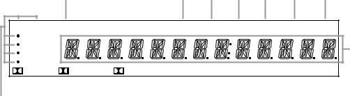
35Information Display: This display delivers messages and status indications to help you operate the receiver. Refer to the separate diagram for complete explanation of the FL display.
36Remote Sensor Window: The sensor behind this window receives infrared signals from the remote control. Aim the remote at this area and do not block or cover it unless an external remote sensor is installed.
37Numeric Keys: Press these buttons to enter or recall stations entered to the tuner’s preset memory. See page 25 for complete information on using the tuner and the preset memories.
AVR55 120 volt Rev (c) 10/1/97
Front Panel Information Display
7
ML K J I H G
VID 1 REC |
CONTOUR |
|
STEREO |
T• MON |
TUNED |
AUTO |
MEMORY |
PRESET |
|
TV |
|
|
|
|
|
|
|
|
|
DVD |
|
|
|
|
|
|
|
|
F |
VID 2 |
|
|
|
|
|
|
|
|
|
SOURCE |
3 - STEREO |
|
|
|
|
|
|
|
|
DIGITAL |
PRO LOGIC |
THEATER |
HALL |
STADIUM |
CHURCH |
SLEEP |
|||
|
|
|
|
|
|
|
|
|
|
|
|
|
|
|
|
|
|
|
|
|
|
|
|
|
|
|
|
|
|
|
|
|
|
A B |
C |
|
|
D |
|
E |
||||||||||
AVid 1 Record Indicators |
|
|
|
|
FMain Information Display |
KT-Mon Indicator |
||||||||||
BDolby Digital Indicator |
|
|
|
|
GPreset Indicator |
LStereo Indicator |
||||||||||
CAnalog Dolby Surround Mode Indicators |
HMemory Indicator |
MContour Indicator |
||||||||||||||
DAnalog Surround Mode Indicators |
IAuto Mode In Indicator |
|
|
|
||||||||||||
ESleep Indicator |
|
|
|
|
JTuned Indicator |
|
|
|
||||||||
AVid 1 Record Indicators: A dot appears next to one of the sources shown in this indicator to tell you which input has been selected as the output to the device connected to the Video 1 Out jacks ›. Press the Vid 1 Rec button &to change the source.
BDolby Digital Indicator: This indicator illuminates when a Dolby Digital source is being played.
CAnalog Dolby Surround Mode Indicators: These indicators illuminate when one of the analog (matrix) dolby Surround modes is in use.
DAnalog Surround Mode Indicators: These indicators illuminate when one of the DSP generated analog surround modes is in use.
ESleep Indicator: This indicator is illuminated when the Sleep function is in use. The number that appears above the indicator is the number of minutes remaining before the AVR55 will return to the Standby mode.
FMain Information Display: This display shows messages relating to the status, input source, surround mode, tuner, volume level or other aspects of unit’s operation.
GPreset Indicator: This indicator illuminates when one of the stations entered into the preset memory is tuned. The number that appears below the indicator is the preset station’s memory.
HMemory Indicator: This flashes after the Memo button 4uhas been pressed to indicate that you should quickly select and enter a preset memory location for a specific radio station.
IAuto Mode In Indicator: This indicator illuminates when the “Auto” mode is in use for FM tuning.
JTuned Indicator: This indicator illuminates when a station is being received with sufficient signal strength to allow for acceptable listening quality.
KT-Mon Indicator: This indicator illuminates when the Tape Monitor function is in use to remind you that you are listening to the record output of the device connected to the Tape 1 Record jacks ‚, not to the actual input source shown in the
Information Display.
LStereo Indicator: This indicator illuminates when an FM station is being tuned in stereo.
MContour Indicator: This indicator illuminates when the Contour circuits have been engaged by pressing the
Contour button ¯.
AVR55 120 volt Rev (c) 10/1/97
Rear Panel Connections
|
|
|
|
|
|
|
|
|
8 |
|
|
|
|
|
i |
hg f e |
|
d c ba · ° |
|
‡ |
|||||
|
|
L |
R |
|
|
|
|
IN |
OUT |
|
FRONT SPEAKER (8Ω ) |
AC INPUT |
|
|
|
|
|
|
|
|
|
REMOTE |
|
||
ANTENNA |
MAIN |
|
|
|
|
PHONO |
|
CONTROL |
|
|
~120V/60HZ |
|
|
|
IN |
|
AC-3 |
|
|
|
|
|
|
3.2A |
|
|
|
|
|
|
|
|
|
|
|
|||
|
|
FRONT |
|
RF/PCM |
L |
|
R |
|
|
|
|
|
|
|
|
|
|
|
VIDEO |
|
|
|
|||
|
|
PRE |
|
|
|
|
R |
|
L |
|||
|
|
|
|
|
|
|
|
MON. |
|
|||
|
|
OUT |
|
|
|
|
|
|
|
|
|
|
AM |
|
|
|
|
CD |
|
|
|
VIDEO 2 |
|
|
MODEL NO.: AVR55 |
LOOP |
|
|
|
|
|
|
|
PLAY |
|
|
||
|
|
|
|
|
|
|
|
|
|
HARMAN KARDON |
||
|
|
|
|
|
|
|
|
|
|
|
|
|
|
|
CENTER |
SUB |
COAXIAL/PCM |
TAPE 1 |
|
|
|
|
|
|
NORTHRIDGE |
|
|
PRE-OUT |
WOOFER |
|
|
|
|
IN |
|
|
CALIFORNIA, U.S.A. |
|
FM |
|
|
OUT |
OPTICAL/PCM |
PLAY |
|
|
|
|
|
|
|
|
REAR |
|
|
|
|
|
VIDEO 1 |
R |
|
L |
||
75Ω |
|
|
|
TAPE 1 |
|
|
|
|
||||
|
|
PRE |
|
|
|
|
|
|
|
|
|
|
|
|
OUT |
|
|
REC |
|
|
|
OUT |
|
|
AC OUTLETS |
|
|
L |
R |
|
TAPE 2 |
|
|
|
|
|
|
|
|
|
|
|
|
|
|
|
|
|
|
|
|
SER. NO |
|
|
GND |
PLAY |
|
|
|
DVD |
|
REAR SPEAKER (8Ω ) |
|
|
|
|
|
|
|
|
|
PLAY |
|
|
|
||
|
|
|
|
|
|
|
|
|
|
|
|
|
|
|
|
|
|
TAPE 2 |
|
|
|
|
|
|
|
|
|
|
|
|
REC |
|
|
|
TV/AUX |
|
|
|
|
|
|
|
|
|
|
|
|
|
|
|
|
|
|
|
|
|
L |
|
R |
|
|
|
|
|
|
|
|
|
|
|
|
VIDEO |
L |
R |
|
CENTER SPEAKER (8Ω ) |
SWITCHED |
|
|
|
|
|
|
|
|
|
|
|
||
|
|
|
|
|
|
|
|
|
|
|
|
~120V/60Hz |
|
|
|
|
|
|
|
|
|
|
|
|
TOTAL 100W |
|
|
|
|
|
|
|
|
|
|
|
|
1A MAX |
™ |
|
¢ |
|
§ |
• |
|
‚ |
|
¤ › |
|
|
fl |
¡ |
£ |
|
¶ |
|
ª |
⁄ |
|
‹ |
|
fi |
|
|
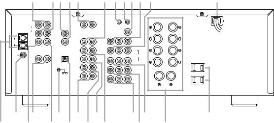
¡ AM Antenna
™ FM Antenna
£ Center Channel Preamp Output
¢ Rear Preamp Outputs
Subwoofer Output
§ Ground Terminal
¶ Optical/PCM Digital Input
• Tape 2 Rec
ª Tape 2 Play
‚Tape 1 Rec
¡AM Antenna: Connect the AM loop antenna supplied with the receiver to these terminals. If an external AM antenna is used, make connections to the AM and GND terminals in accordance with the instructions supplied with the antenna.
™FM Antenna: Connect an indoor or external FM antenna to this terminal.
⁄ Tape 1 Play
¤ TV Inputs
‹ DVD Input
› Video 1 Outputs
fi Speaker Outputs
fl Switched Outlets
‡ AC Power Cord
° Video 1 Inputs
· Video 2 Play Inputs
aVideo Monitor Output
£Center Channel Preamp Output:
These jacks may be used to connect the center channel to an optional, external power amplifier.
¢Rear Preamp Outputs: These jacks may be used to connect the surround channels to an optional, external power amplifier.
Subwoofer Output: Connect this jack to the mono line level input of an optional powered subwoofer, or your optional external subwoofer amplifier.
b Remote Control Extension Output
c Remote Control Extension Input
d CD Input
e Phono Input
f Coax Digital Input
g AC-3 RF Input
h Front Channel Preamp Outputs
iFront Channel Main In Amp Inputs
§Ground Terminal: Connect the ground wire from a turntable to this terminal to reduce system hum.
¶Optical/PCM Digital Input:
Connect the AC-3 RF output of an LV player equipped for digital audio to this jack.
NOTE: Do not connect standard analog audio sources to these jacks
¶ f g.
AVR55 120 volt Rev (c) 10/1/97
Rear Panel Connections
9
• Tape 2 Rec: Connect the RECORD/INPUT jacks of an audio tape recorder to these jacks.
ª Tape 2 Play: Connect the PLAY/OUT jacks of an audio tape recorder to these jacks.
‚ Tape 1 Rec: Connect the RECORD/INPUT jacks of an audio tape recorder to these jacks.
⁄ Tape 1 Play: Connect the PLAY/OUT jacks of an audio tape recorder to these jacks.
NOTE: The recorder connected to the Tape 1/Mon jacks may be monitored during a recording session by pressing the Tape 1/Mon button !don the front panel or remote.
¤ TV Inputs: Connect the audio and video outputs from a TV, Satellite receiver or other A/V source to these jacks. The signal sent to the audio jacks may also be used to trigger the TV Auto On function. (See page 23 for more information on TV Auto On.)
‹ DVD Input: Connect the composite video and analog audio outputs of a DVD player to these jacks.
› Video 1 Outputs: Connect the audio and video REC/IN jacks of your main VCR to these jacks.
NOTE: The Video 1 jacks may be used for any video source, but when used with a VCR they will permit dubbing from one source to another while a separate source is being listened to by selecting the VID 1 Rec button &.
fi Speaker Outputs: Connect these terminals to the input terminals on your front left/right, center and surround speakers.
fl Switched Outlets: These outlets provide AC power only when the AVR55 is turned on. Note that the total power draw of the products connected may not exceed 100 watts.
‡ AC Power Cord: Connect this plug to an unswitched 115 volt AC outlet.
° Video 1 Inputs: Connect the audio and video PLAY/OUT jacks of your main VCR to these jacks.
· Video 2 Play Inputs: Connect the audio and video PLAY/OUT jacks of a VCR, DVD, LD, Satellite system or other video source to these jacks.
a Video Monitor Output: Connect this jack to the video input of a TV or video projector to view the selected source.
b Remote Control Extension Output: This jack may be connected to other compatible Harman Kardon products so that they will receive infrared commands captured by the AVR55’s remote sensor.
c Remote Control Extension Input: If the AVR55’s front panel IR sensor is blocked due to cabinet doors or other obstructions, an external IR sensor may be used. Connect the output of the sensor to this jack.
d CD Input: Connect the output of your CD player or D/A converter to these jacks.
e Phono Input: Connect the output of your turntable or tone arm to these jacks. Note that only Moving Magnet (MM) type cartridges may be used.
f Coax Digital Input: Connect the coax digital output from a DVD player, HDTV receiver, LV player or CD player to this jack. The signal
may be either a Dolby Digital (AC-3) signal or a standard PCM digital source.
g AC-3 RF Input: Connect the AC-3 RF output of an LV player equipped for digital audio to this jack.
NOTE: Do not connect standard analog audio sources to these jacks
¶ f g
h Front Channel Preamp Outputs:
These jacks provide the output for the front left and right channels to an external amplifier or processor. In normal operation, unless an external power amplifier is used, the jumper pins should remain connected
to the Front Main In jacks i.
i Front Channel Main In Amp Inputs: These jacks are the input to the AVR 51’s front left/right channel power amplifier. Unless an external power amplifier is used for the left/right channels, the jumper pins should remain connected to the
Front Pre Out jacks h.
AVR55 120 volt Rev (c) 10/1/97

Remote Control Functions
|
|
|
|
|
|
10 |
|
|
Sending |
|
Learning |
|
|
||
a |
Use |
Learn |
|
|
|
|
|
b |
|
|
|
|
|||
ON |
OFF |
ON |
OFF |
SLEEP |
|
|
|
c |
|
|
|||||
|
Main Power |
Source Power |
|
|
|
||
d |
PHONO AC-3 |
P/L |
3 ST |
|
z` |
||
TV |
|
STEREO |
MATRIX |
|
|||
e |
DVD |
NIGHT |
1 |
2 |
3 |
xy |
|
f |
VID 1 |
DELAY |
|
|
|
|
|
|
|
|
|
|
w |
||
g |
|
|
|
|
|
|
|
VID 2 |
RF |
7 |
8 |
9 |
|
|
|
h |
|
OPT |
|
|
# |
|
|
|
|
M E M O C L E A R |
v |
u |
|||
|
|
|
P-SCAN |
|
|||
|
AM/FM COAX |
+ |
SKIP |
|
|||
i |
t |
|
|||||
|
|
PRESET |
TUNE/ |
s |
|||
|
CD |
|
|
||||
|
|
DISC |
SEARCH |
r |
|||
|
|
|
|||||
d |
TAPE 1 |
|
|
|
|
|
q |
|
|
FM |
P T Y |
A F |
|
||
|
TAPE 2 |
|
|
|
|||
|
|
DISPLAY |
RDS DISP. |
MUTE |
p |
o |
|
|
|
SELECT |
|
|
|
||
j |
|
|
TEST TONE |
|
|
||
|
|
|
|
|
|
||
|
|
|
|
|
|
|
|
|
|
|
|
CH SELECT |
|
|
|
k |
|
|
|
VOLUME |
n |
|
|
|
|
|
|
|
|||
l |
|
|
|
SPEAKER |
|
|
|
|
|
|
|
|
|
|
|
|
|
AVR 55 |
|
|
|
||
|
|
|
|
m |
|
|
|
aUse/Learn bSource Power cMain Power
dAudio Source Selectors eVideo Source Selectors fNight Mode
gDelay
hDigital Audio Input Selectors iAM/FM
jSelect k Test Tone
l Channel Select
mSpeaker Level Adjust nMain Volume
oDisplay pMute
qTransport Controls
rTune/Search and Fast Forward sPreset/Disc
tChannel/Skip uMemo
vP-Scan
wNumber Keys
xStereo Selector
yMatrix Surround Modes zAC-3 Select
`Dolby Surround Modes
 Sleep
Sleep
 Learning LED
  Sending LED
AVR55 120 volt Rev (c) 10/1/97
 Loading...