


AVR70 engelsk manual 11/01/98 11:57 Side 1
Harman Kardon
AVR70
Audio/VideoReceiver
|
|
|
|
|
|
|
|
|
|
|
|
|
|
|
|
Volume |
|
VISUAL |
TV |
LD |
VCR 12 AUX TEST |
MEMO |
AUTO |
TUNED |
STEREO |
|
|
|
|
|
|
|
|||
SIGNAL CH |
|
|
|
|
|
|
|
|
dB |
|
|
|
|
|
|
|
|
EVEL |
|
|
|
|
|
|
|
|
|
kHz |
|
|
|
|
|
|
|
|
|
|
|
|
|
|
|
|
|
|
|
|
|
|
|
|
|
|
|
|
|
|
|
|
|
|
|
MHz |
|
|
|
|
|
|
|
STEREO |
|
PRO•LOGIC |
MOVIE |
HALL |
MATRIX |
|
|
|
|
|
|
|
|
|
|
||
|
|
3-LOGIC |
AUTO MEMO |
P-SCAN |
|
|
|
|
DISP |
|
|
|
|
|
|
|
|
Aux |
|
|
|
DISP |
OSD |
|
Delay |
|
MODE |
|
P•SET |
|
P•Scan |
TUNE |
Mute |
|
|
ar |
Mode |
|
|
|
RDS |
|
|
|
|
Bass |
|
Treble |
|
Balance |
|
AUX |
|
DISP. |
|
AF |
|
PTY. |
|
|
|
|
|
|
|
|
|
|
|||
|
|
|
|
|
|
|
|
|
Min |
Max |
Min |
Max |
L |
R |
VIDEO |
L–AUDIO–R |
|
|
|
|
|
|
|
|
|
|
|
|
|
|
|
|
|
||
Owner’s Manual
AVR70 engelsk manual 11/01/98 11:57 Side 2
Declaration of Conformity
We, Harman Kardon Europe A/S
Kongevejen 194B
DK-3460 Birkerød
DENMARK
declare in own responsibility, that the product described in this owner's manual is in compliance with technical standards:
EN 55 013
EN 55 020
EN 55 022
EN 60 065
EN 60 555-2-3
Steen Michaelsen
Harman Kardon Europe A/S
Birkerød, DENMARK
11/95
AVR70 engelsk manual 11/01/98 11:57 Side 3
Front Panel
|
|
|
|
2 |
|
|
|
|
|
|
1 |
|
|
|
|
|
|
|
|
|
|
|
|
|
|
|
AVR70 |
|
|
|
|
|
|
|
|
|
|
|
|
|
|
|
|
|
|
|
|
|
|
|
|
|
|
|
|
|
|
|
|
|
|
|
|
|
|
|
|
|
|
Volume |
|
|
|
|
|
|
|
|
|
|
VISUAL |
|
|
|
TEST |
MEMO |
AUTO |
TUNED STEREO |
|
|
|
|
|
|
& |
|
|
|
|
|
|
|
|
|
LEVELSIGNAL CH TV |
LD VCR 12 AUX |
|
|
|
dB |
|
|
|
|
|
|
|||
|
|
|
|
|
|
|
|
|
|
|
|
|
|
|
|
kHz |
|
|
|
|
|
|
|
|
|
|
|
|
|
|
|
|
|
|
|
|
|
|
|
MHz |
|
|
|
|
|
|
|
|
|
|
|
|
|
|
|
|
STEREO |
|
PRO•LOGIC MOVIE |
HALL |
MATRIX |
|
|
|
|
|
|
|
|
|
|
|
|
|
|
|
|
|
|
|
|
|
3-LOGIC AUTO MEMO |
P-SCAN |
|
|
DISP |
|
|
|
|
|
|
|
|
|
AM/FM |
CD |
T-MON |
T·2 |
TV |
LD |
VCR1 |
VCR 2 |
Aux |
|
DISP |
OSD |
Delay |
|
MODE |
|
P•SET |
|
P•Scan |
TUNE |
Mute |
|
|
|
|
|
|
|
|
|
|
|
|
|
|
|
|
|
|
|
|
|
|
|
|
|
^ |
Power |
Phones |
|
|
|
|
|
Memo |
Clear |
Mode |
|
RDS |
|
|
|
Bass |
|
Treble |
|
Balance |
|
AUX |
||
|
|
|
|
|
DISP. |
AF |
|
PTY. |
|
|
|
|
|
|
|
|
|
||||||
|
|
|
|
|
|
|
|
|
|
|
|
|
|
|
|
Min |
Max |
Min |
Max |
L |
R |
VIDEO |
L–AUDIO–R |
|
|
|
|
|
|
|
|
|
|
|
|
|
|
|
|
|
|
|
|
|
|
||
|
3 45 6 7 8 9 ) !@ # $ % |
|
|
||||||||||||||||||||
* ( |
|
|
|
|
|
Ó Ô ÒÚ Û Ù ı ˆ |
|
˜ |
|||||||||||||||
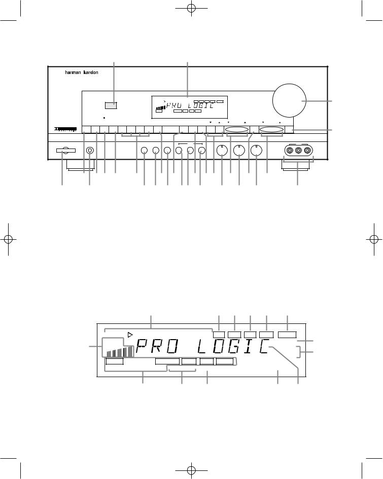
1Information display |
!Delay |
|
2Remote Sensor Window |
@Mode |
ÔClear |
3AM/FM Tuner Mode Selection |
#Preset Tuning |
FM Mode |
4CD |
$P-Scan |
ÒRDS Display |
5Tape1/Monitor |
%Tune |
ÚRDS Alternate Frequency |
6Tape 2 |
^Mute |
ÛRDS Programme Type |
7Video Sources |
&Volume Control |
ÙBass |
8Aux |
*Power |
ıTreble |
9Display |
(Headphone Jack |
ˆBalance |
)OSD (On Screen Display) |
ÓMemo |
˜Front Panel Inputs |
Information Display
|
|
|
¡ |
|
™ £ ¢ |
§ |
|
||
|
VISUAL |
TV |
LD VCR 12 AUX TEST MEMO |
AUTO TUNED |
STEREO |
¶ |
|||
› |
SIGNAL |
CH |
|
|
|
|
|
dB |
|
LEVEL |
|
|
|
|
|
MHzkHz |
• |
||
|
|
|
|
|
|
|
|
||
|
STEREO |
|
|
PRO•LOGIC MOVIE |
HALL |
MATRIX |
|
|
|
|
|
|
|
3-LOGIC AUTO MEMO |
P-SCAN |
|
DISP |
|
|
|
|
|
‹ |
¤ |
⁄ |
|
|
‚ ª |
|
¡ “Visual” Indicators |
|
|
§ Stereo |
|
|
|
|
|
|
™ Test |
|
|
¶ Volume Indication |
|
|
⁄ P-Scan |
|
|
|
£ Memo |
• Tuner Frequency Indication |
¤ Auto Memo |
¢ Auto |
ª Main Information Display |
‹ Mode Statue |
Tuned |
‚ Display |
› Signal Level Indication |

AVR70 engelsk manual 11/01/98 11:57 Side 4
Rear Panel – Audio and System Connections
é |
|
|
|
|
|
TV |
|
|
|
CENTER |
|
|
|
|
|
|
|
|
|
MONI |
PRE OUT |
|
|
|
|
|
|
||
|
|
|
|
|
|
|
|
8OHMS |
|
|
|
|||
|
ANTENNA |
|
|
OUT |
|
OUT |
L |
|
|
|
|
|
|
|
|
|
|
|
|
|
|
|
|
|
|
|
|||
|
|
|
|
VCR2 |
|
VCR2 |
FRONT |
|
|
|
˚ |
|
|
ß |
|
AM |
|
OUT |
IN |
|
IN |
R |
|
|
|
AC OUTLETS |
|||
|
|
TAPE2 |
|
|
|
|
|
|
SURR. |
|
230V |
50/60Hz) |
|
|
|
|
|
|
|
|
|
|
¬ |
|
|
|
|||
GND |
|
|
|
|
|
|
|
|
|
|
|
|||
ƒ |
|
IN |
OUT |
|
OUT |
L |
|
|
|
|
|
|
||
|
|
|
|
|
8OHMS |
|
|
|
||||||
|
|
|
|
|
|
|
|
|
|
|
|
|
||
|
|
|
VCR1 |
|
VCR1 |
SURR. |
|
|
|
|
|
|
|
|
å |
FM |
|
OUT |
IN |
|
IN |
R |
|
|
|
|
|
|
® |
(75Ω ) |
|
|
|
|
|
|
|
|
||||||
|
|
|
|
|
|
|
|
|
|
|
|
|||
ç |
|
|
TAPE1 |
|
|
|
|
|
|
|
˙ |
|
|
|
|
|
IN |
LD |
|
LD |
|
|
|
|
|
|
œ |
||
|
|
|
|
|
|
|
|
|
|
|
||||
|
|
|
|
|
|
CENTER |
OUT |
IN |
FRONT |
î |
|
|
||
|
|
|
CD |
TV |
|
TV |
|
|
REMOTE |
8OHMS |
|
|
|
|
© |
|
|
|
|
|
CONT. |
|
|
|
|
|
|||
|
|
|
|
|
|
|
|
|
|
SWITCHED |
UNSWITCHED |
|
||
|
|
|
|
|
|
|
|
|
|
|
|
|||
L |
R |
L |
R |
|
|
SUB |
|
|
|
|
|
|
|
|
|
|
|
AUDIO |
|
VIDEO |
S-VIDEO |
WOOFER |
|
R |
L |
|
|
|
|
|
|
|
|
|
|
|
|
|
|
SPEAKERS |
|
|
|
|
|
|
|
|
|
|
|
µ ñ |
ø |
|
|
|
|
|
|
åFM Antenna |
˙Front R |
|
|
AM Antenna |
îFront L |
|
|
çTape 1 Out |
Center |
øRemote IR Out |
|
Tape 1 |
In |
˚Surround R |
Remote IR In |
éTape 2 |
Out |
¬Surround L |
œUnswitched AC Outlet |
ƒTape 2 |
In |
µPre-Outs |
®Switched AC Outlet |
©CD IN |
|
ñSubwoofer Pre-Out |
ßPower Cable |
Rear Panel – Video Connections
|
|
|
|
|
TV |
P |
Q |
|
CENTER |
|
ANTENNA |
|
|
|
|
MONI |
|
|
8OHMS |
|
|
|
|
|
OUT |
OUT |
J |
|
|
|
|
|
|
H |
|
|
|
|
|
|
|||
|
|
|
VCR2 |
VCR2 |
|
|
|
|
||
AM |
|
OUT |
|
IN |
IN |
I |
|
|
AC OUTLETS |
|
|
GTAPE2 |
|
|
|
E |
|
230V |
50/60Hz) |
||
GND |
|
|
|
|
SURR. |
|
||||
|
IN |
|
OUT |
OUT |
D |
|
|
|
||
|
B |
|
|
8OHMS |
|
|||||
|
|
|
|
|
|
|
|
|||
|
|
|
VCR1 |
VCR1 |
F |
|
|
|
||
FM |
|
OUT |
|
IN |
IN |
C |
|
|
|
|
(75Ω ) |
ATAPE1 |
|
|
|
O |
|
|
|
||
|
M |
IN |
|
LD |
LD |
N |
|
|
|
|
|
|
|
|
|
|
|
FRONT |
|
||
|
|
|
|
|
OUT |
IN |
|
|
||
|
K |
CD |
|
TV |
TV |
L |
|
REMOTE |
8OHMS |
|
|
|
|
CONT. |
|
|
|||||
|
|
|
|
|
|
SWITCHED |
UNSWITCHED |
|||
|
|
|
|
|
|
|
||||
L |
R |
|
L |
R |
|
|
|
|
|
|
|
|
AUDIO |
|
VIDEO |
S-VIDEO |
|
|
R |
L |
|
|
|
|
|
|
|
|
|
|
SPEAKERS |
|
AVCR 1 Audio In |
GVCR 2 |
Audio In |
|
|
BVCR 1 Audio Out |
HVCR 2 Audio Out |
MLD Audio In |
||
CVCR 1 |
Video In |
IVCR 2 |
Video In |
NLD Video In |
DVCR 1 |
Video Out |
JVCR 2 |
Video Out |
OLD S Video In |
EVCR 1 |
S Video Out |
KTV Audio In |
PTV Monitor Video Out |
|
FVCR 1 |
S Video In |
LTV Video In |
QTV Monitor S Video Out |
|
AVR70 engelsk manual 11/01/98 11:57 Side 5
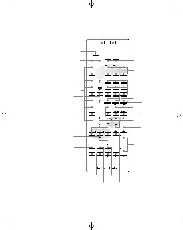
Remote Control
aUse/Learn
bMain Power
cSource Selection dSource Power
eSurround Mode Selection fMain Volume
gTV Volume hMute
iTransport Controls
jTune/Search & Fast Forward k Channel/Skip
l Disc/Deck/Ant
mNumber Keys nP-Scan
oMemo
pDelay
qMenu Controls rSelect
sScreen Display
tPanel Display uTest Noise
vSpeaker Select wLevel Adjust xSending LED yLearn LED
zRDS PTY
`RDS AF
xy
Sending |
Learning |
a |
Use |
Learn |
|
|
|
|
|
|
|
|
|
||
d |
Source Power |
Main Power |
|
b |
||
|
OFF |
|
|
|
|
|
|
TV |
|
P/L |
ST |
MOVIE |
|
|
LD |
|
MATRIX |
HALL |
STEREO |
e |
|
VCR1 |
DELAY |
|
|
|
|
p |
VCR2 |
|
ABC |
DEF |
GHI |
m |
|
|
4 |
5 |
6 |
||
c |
AUX |
|
JKL |
MNO |
PQR |
|
PTY |
7 |
8 |
9 |
|
||
z |
AM/FM |
|
STU |
VWX |
|
o |
|
AF |
|
0 |
|
||
` |
CD |
|
MEMO |
CLEAR |
P•SCAN |
n |
|
|
|
|
|
k |
|
|
|
DISC |
|
CHANNEL/SKIP |
||
|
|
|
|
|||
|
Tape1(MON) DECK |
|
|
|||
|
|
|
|
j |
||
|
|
ANT. |
|
|
|
|
|
|
|
|
|
|
|
l |
Tape2 |
|
|
TUNE/SEARCH |
|
|
|
|
|
|
|
i |
|
|
|
REC |
|
|
|
|
|
|
|
|
MUTE |
|
|
|
|
|
|
|
h |
|
q |
|
|
|
STOP |
|
|
|
SELECT |
|
|
|
||
|
|
|
|
|
||
r |
|
|
|
|
|
|
SCREEN SPEAKER |
V O L U M E |
f |
s |
|
|
DISPLAY
t
PANEL TEST ADJUST
DISPLAY NOISE
TV MAIN

 RDS
RDS
uw v g

AVR70 engelsk manual 11/01/98 11:57 Side 6
Table of Contents
Introduction . . . . . . . . . . . . . . . . . . . . . . . . . . . . . . . . . . 1
Features . . . . . . . . . . . . . . . . . . . . . . . . . . . . . . . . 1
Safety Information . . . . . . . . . . . . . . . . . . . . . . . . . . . . . 2
Unpacking and Installation . . . . . . . . . . . . . . . . 3
Conventions. . . . . . . . . . . . . . . . . . . . . . . . . . . . . 3
Front Panel Controls . . . . . . . . . . . . . . . . . . . . . . . . . . . . 4
Front Panel Information Display . . . . . . . . . . . . . . . . . . 5
Rear Panel Audio & Systems Connections . . . . . . . . . . . 6
Rear Panel Video Connections . . . . . . . . . . . . . . . . . . . . 7
Remote Control Functions . . . . . . . . . . . . . . . . . . . . . 8–9
Installation, Set Up and Configuration . . . . . . . . . 10–11
Remote Control Programming and Operation . . . 12–13
System Configuration . . . . . . . . . . . . . . . . . . . . . . . 14–16
Basic Operation. . . . . . . . . . . . . . . . . . . . . . . . . . . . 17–22
Source Selection . . . . . . . . . . . . . . . . . . . . . . . . 17
Volume Control . . . . . . . . . . . . . . . . . . . . . . . . . 17
Surround Mode Selection. . . . . . . . . . . . . . 17–18
TV Auto Function . . . . . . . . . . . . . . . . . . . . . . . 18
Tuner Operation . . . . . . . . . . . . . . . . . . . . . 18–20
RDS Operation . . . . . . . . . . . . . . . . . . . . . . 21–22
On Screen Display . . . . . . . . . . . . . . . . . . . . . . . . . . 23–24
Advanced Functions . . . . . . . . . . . . . . . . . . . . . . . . 25–26
Audio/Video Simulcast . . . . . . . . . . . . . . . . . . . 25
Delay Time Adjust . . . . . . . . . . . . . . . . . . . . . . . 25
Surround Mode Chart . . . . . . . . . . . . . . . . . . . . 26
Troubleshooting Chart . . . . . . . . . . . . . . . . . . . . . . . . . 27
Technical Specifications . . . . . . . . . . . . . . . . . . . . . . . . 28

AVR70 engelsk manual 11/01/98 11:57 Side 1
Introduction
1
Congratulations! With the purchase of a Harman Kardon AVR70 you are about to begin many years of listening enjoyment. The AVR70 has been custom designed to provide all the excitement and detail of movie soundtracks and every subtle nuance of musical selections.
While complex digital systems are hard at work within the AVR70 to make all of this happen, hook-up and operation are simple. Color keyed connections, a comprehensive remote control and on screen menus make the AVR70 easy to use. To obtain the maximum enjoyment from your new receiver we urge you to take a few minutes to read through this manual. This will ensure that connections to speakers, source playback units and other external devices are made properly. In addition, a few minutes spent learning the functions of the various controls will enable you to take advantage of all the power the AVR70 is able to deliver.
If you have any questions about this product, its installation or operation, please contact your retailer or custom installer. They are your best local source of information.
Description and Features
The AVR70 is a full featured A/V receiver, incorporating a wide variety of listening options. In addition to standard Dolby® Pro Logic™ processing, the AVR70 uses Digital Signal Processing to provide other surround modes.
A total of five audio/video inputs, some with both composite and “S” video, as well as three additional audio only inputs are selected through a learning remote control and an easy to read front panel display or on screen graphics through a TV monitor.
The AVR70’s powerful amplifier uses traditional Harman Kardon High Current design philosophies to meet the wide dynamic range of any program selection.
Harman Kardon invented the high fidelity receiver over forty years ago. With state of the art circuitry and time honored circuit designs, the AVR70 is one of the finest receivers ever offered by Harman Kardon.
■Digital Signal processing for precise surround decoding
■Dolby ProLogic, Dolby 3 Stereo and three other surround modes
■On screen menu displays
■Learning remote control
■Composite and “S” video switching
■Preamp output for ALL channels permits ease of expansion
■“TV Auto” function simplifies remote operation of the AVR70 and a TV set
■RDS Programme Information System
ENGLISH
AVR70 engelsk manual 11/01/98 11:57 Side 2
ENGLISH
Safety Information
2
Important Safety Information
Verify Line Voltage Before Use
Your AVR70 has been designed for use with 220–240 volt AC current. Connection to a line voltage other than that for which it is intended can create a safety and fire hazard, and may damage the unit.
If you have any questions about the voltage requirements for your specific model, or about the line voltage in your area, contact your selling dealer before plugging the unit into a wall outlet.
Do Not Use Extension Cords
To avoid safety hazards, use only the power cord attached to your unit. We do not recommend that extension cords be used with this product. As with all electrical devices, do not run power cords under rugs or carpets or place heavy objects on them.
Handle the AC Power Cord Gently
When disconnecting the power cord from an AC outlet, always pull the plug, never pull the cord. If you do not intend to use the unit for any considerable length of time, disconnect the plug from the AC outlet (Attention: Than memory may be lost after some days).
Do Not Open The Cabinet
There are no user serviceable components inside this product. Opening the cabinet may present a shock hazard, and any modification to the product will void your guarantee. If water or any metal object such as a paper clip, wire or a staple accidentally falls inside the unit, disconnect it from the AC power source immediately, and consult an authorized service station.
Installation Location
■To assure proper operation, and to avoid the potential for safety hazards, place the unit on a firm and level surface. When placing the unit on a shelf, be certain that the shelf and any mounting hardware can support the weight of the product.
■Make certain that proper space is provided both above and below the unit for ventilation. If this product will be installed in a cabinet or other enclosed area, make certain that there is sufficient air movement within the cabinet. Under some circumstances a fan may be required.
■Do not place the unit directly on a carpeted surface.
■Avoid installation in extremely hot or cold locations, or an area that is exposed to direct sunlight or heating equipment.
■Avoid moist or humid locations.
■Do not obstruct the ventilation slots on the top of the unit, or place objects directly over them.
Cleaning
When the unit gets dirty, wipe it with a clean, soft dry cloth. If necessary, wipe it with a soft cloth dampened with mild soapy water, then a fresh cloth with clean water. Wipe dry immediately with a dry cloth. NEVER use benzene, aerosol cleaners, thinner, alcohol or any other volatile cleaning agent. Do not use abrasive cleaners, as they may damage the finish of metal parts. Avoid spraying insecticide near the unit.
Moving The Unit
Before moving the unit, be certain to disconnect any interconnection cords with other components, and make certain that you disconnect the unit from the AC outlet.
AVR70 engelsk manual 11/01/98 11:57 Side 3
Safety Information
3
Unpacking and Installation
The carton and shipping materials used to protect your new receiver during shipment were specially designed to cushion it from shock and vibration. We suggest that you save the carton and packing materials for use in shipping if you move or should the unit ever need repair.
To minimize the size of the carton in storage, you may wish to flatten it. This is done by carefully slitting the tape seams on the bottom and collapsing the carton down to a more two dimensional appearance. Other cardboard inserts may be stored in the same manner. Packing materials that cannot be collapsed should be saved along with the carton in a plastic bag.
If you do not wish to save the packaging materials, please note that the carton and other sections of the shipping protection are recyclable. Please respect the environment and discard those materials at a local recycling center.
How to Connect a Plug
The wires in the mains lead are coloured in accordance with the following code:
BLUE – “NEUTRAL” (“N”)
BROWN – “LIVE” (“L”)
1.The BLUE wire must be connected to the terminal which is marked with the letter “N” or coloured BLACK.
2.The BROWN wire must be connected to the terminal which is marked with the letter “L” or coloured RED.
3.Do not connect either wires to the earth terminal in the plug which is marked my the letter “E” or by the safety earth symbol  or coloured green or green- and-yellow.
Before replacing the plug cover, make certain that the cord grip is clamped over the sheath of the lead – not simply over the two wires.
Conventions
In order to help you use this manual with the remote control, front panel
controls, rear panel connections and on-screen menus, certain conventions have been used.
EXAMPLE – (bold type) indicates a specific remote control or front panel button, or rear panel connection jack
EXAMPLE – (OCR type) indicates a message that is visible through the onscreen menu system
1– (number in a square) indicates a specific front panel control
¡ – (number in a circle) indicates an indicator in the main front panel display
a– (number in an oval) indicates a button or indicator on the remote
å– (letter in a circle) indicates a rear panel Audio or System connection
A– (letter in a square) indicates a specific rear panel video connection
ENGLISH
AVR70 engelsk manual 11/01/98 11:57 Side 4
ENGLISH
Front Panel Controls
4
1Information Display: This display delivers messages and status indications to help you operate the receiver. Refer to the separate diagram for a complete explanation of the FL display.
2Remote Sensor Window: The sensor behind this window receives infrared signals from the remote control. Aim the remote at this area and do not block or cover it unless an external remote sensor is installed.
3AM/FM Tuner Mode Selection:
Press this button once to select the tuner. Press it again to switch between FM, MW and LW.
4CD: Press this button to select the CD player.
5Tape1/Monitor: Press this button to select Tape One as the input source. A red LED above the button will illuminate to indicate that the Tape Monitor has been selected.
6Tape 2: Press this button to select Tape 2.
7Video Sources: Press any of these buttons to select a video input source.
8Aux: Press this button to select the source connected to the front panel Aux jacks.
9Display: Press this button to
turn off the front panel FL display. The DISP indicator will illuminate
to remind you that the unit is still turned on.
)OSD (On Screen Display): Press the button briefly to display a system status report on your video screen. Press and hold to change the video standard.
!Delay: Press this button to increase the delay to the rear (surround) channels.
@Mode: Press these buttons to scroll up ⁄ or down ¤ through the list of available surround modes.
#P-Set: Press these buttons to manually scroll up ⁄ or down ¤ through the FM, LW or AM stations programmed into the receiver’s preset memory.
$P-Scan: Press this button to automatically scan through the FM or AM stations preset into the receiver’s memory. Press the button again to stop the scan when the tuner is at the desired station.
%Tune: Press these buttons to manually or automatically scan up ⁄ or down ¤ through the FM or
AM bands.
^Mute: Press this button to cut the output to the speakers. Press it again to return to the previous volume level.
&Volume Control: Turn the knob clockwise to increase volume, counterclockwise to decrease the volume. Note that approximately two revolutions of the knob are required to go from no output to maximum volume.
*Power: Press this button to turn the unit on or off.
NOTE: When the Power Switch is in the “OFF” position, the unit is in a “Standby” condition and is NOT disconnected from the AC mains supply.
(Headphone Jack: Plug standard stereo headphones into this jack for private listening.
NOTE: When the headphones are in use the output to the speakers is muted and the surround mode is automatically switched to STEREO. When the headphones are removed from the jack, sound to the speakers is restored and the unit returns to the previous sound mode.
ÓMemo: The memo button is used to enter stations to the tuner’s preset memory in either the manual or automatic modes. It is also used in clearing the memory and entering the sleep timer period.
ÔClear: The clear button is used to cancel tuning, memory input or when clearing the unit’s memories.
FM Mode: Press this button
to select the receiving mode for FM stations (Stereo/Mono/Auto).
ÒRDS Display: When a station transmitting RDS data is tuned, press this button to view the tuning frequency.
ÚRDS AF: The button is used to search for stations transmitting a specific programme that may offer better reception than the currently tuned station.
ÛRDS PTY: Press this button to view the programme type (PTY) when an RDS station is tuned. It is also used to initiate a search for RDS stations transmitting a specific programme type.
ÙBass: This knob adjusts the tone of low frequency sounds. Turn it to the right to boost bass frequencies or to the left to cut bass frequencies.
ıTreble: This knob adjusts
the tone of high frequency sounds. Turn to it the right to boost high frequencies or to the left to cut high frequencies.
ˆBalance: This knob adjusts the balance between the front left and right speakers.
˜Front Panel Inputs: Audio or Video sources connected to these jacks may be selected by pressing the Aux button 8.
AVR70 engelsk manual 11/01/98 11:57 Side 5
Front Panel Information Display
5
ENGLISH
¡“Visual” Indicator: These indicators display which video source is being fed to the video monitor output.
™ Test: This indicator flashes when the output levels are being set using the built in test signal generator.
£ Memo: This indicator flashes when the Memo button is pressed when entering presets and other information into the tuner’s memory.
¢ Auto: This indicator signifies that the Automatic Receiving mode (Stereo/Mono) is in use for FM broadcasts.
Tuned: This indicator lights when an AM or FM station is properly tuned and locked.
§ Stereo: This indicator lights when an FM station is broadcasting in stereo.
¶ Volume Indication: The last two indicators on the information display indicate the volume level. Note that 0dB is the reference level, not an indication that there is no output.
• Tuner Frequency Indication:
When the tuner is in use, the main Information Display will show the preset channel number, if any, the frequency band and the station frequency. Indicators at the right side of the display show kHz when an LW or MW station is tuned or MHz when an FM station is tuned.
ª Main Information Display: This ten digit display shows messages relating to the status, input source, surround mode, tuner, volume level or other aspects of the unit’s operation.
‚ DISP: This indicator lights when the FL display has been turned
off using the Display button )to remind you that the unit is still turned on.
⁄ P-Scan: This indicator flashes when the stations programmed into the tuner memory are being automatically reviewed.
¤ Auto Memo: This indicator flashes when the tuner is automatically scanning for stations and entering them into the preset memory.
‹ Mode Status: These indicators display the currently selected surround mode.
› Signal Level Indication: This is a visual indication of the strength of a radio station signal. The more bars visible, the stronger the station.
 Loading...