


Harman Kardon
AVR45
Audio/VideoReceiver
Récepteur Audio/Vidéo
Volume
|
|
|
|
|
Speaker |
Channel Dig. Select |
Delay |
|
|
ITAL |
|
|
|
|
|
Set |
|
|
|
COAX |
AC-3 |
|
|
|
|
|
|
|
|
TUNNING |
PRESET SCAN |
PRESET |
FM MODE |
DIGITAL |
PRO LOGIC |
3-STEREO HALL 1 |
HALL 2 |
THEATER |
TEST TONE SURR. OFF |
Mute
|
Bass |
Treble |
|
Balance |
|
VIDEO 3 |
|
Min |
Max |
Min |
Max |
L |
R |
Video |
L Audio R |
Owner’s Manual Manuel de l’Utilisateur

Owner’s Manual
AVR45 Audio/Video Receiver
Table of Contents
Introduction. . . . . . . . . . . . . . . . . . . . . . . . . . . . . . . . . . . . . . . . . 1
Safety Information . . . . . . . . . . . . . . . . . . . . . . . . . . . . . . . . . 2–3
Front Panel Controls . . . . . . . . . . . . . . . . . . . . . . . . . . . . . . . 4–6
Front Panel Information Display . . . . . . . . . . . . . . . . . . . . . . 7–8
Rear Panel Connections . . . . . . . . . . . . . . . . . . . . . . . . . . . . 9–10
Remote Control Functions . . . . . . . . . . . . . . . . . . . . . . . . . 11–13
Installation and Connections. . . . . . . . . . . . . . . . . . . . . . . 14–15
System Configuration . . . . . . . . . . . . . . . . . . . . . . . . . . . . . 16–21
Operation. . . . . . . . . . . . . . . . . . . . . . . . . . . . . . . . . . . . . . . 22–27
Source Selection . . . . . . . . . . . . . . . . . . . . . . . . . . . . . . 22
Surround Mode Selection . . . . . . . . . . . . . . . . . . . . 22–24
Surrond Mode Chart . . . . . . . . . . . . . . . . . . . . . . . . . . . 23
Digital Audio Playback . . . . . . . . . . . . . . . . . . . . . . 24–26
Tuner Operation . . . . . . . . . . . . . . . . . . . . . . . . . . . . . . 26
Tape Recording . . . . . . . . . . . . . . . . . . . . . . . . . . . . 26–27
Output Level Trim Adjustment . . . . . . . . . . . . . . . . . . . 27
Six-Channel Direct Input . . . . . . . . . . . . . . . . . . . . . . . 27
Programming the Remote . . . . . . . . . . . . . . . . . . . . . . . . . 28–40
Direct Code Entry. . . . . . . . . . . . . . . . . . . . . . . . . . . . . . 28
Auto Search Method . . . . . . . . . . . . . . . . . . . . . . . . 28–29
Code Readout. . . . . . . . . . . . . . . . . . . . . . . . . . . . . . . . . 29
Programmed Device Functions . . . . . . . . . . . . . . . 29–30
Macro Programming . . . . . . . . . . . . . . . . . . . . . . . 30–31
Volume Punch-Through . . . . . . . . . . . . . . . . . . . . . . . . 31
Re-Assigning Device Control Selectors . . . . . . . . . . . . . 31
Function List . . . . . . . . . . . . . . . . . . . . . . . . . . . . . . 32–33
Setup Code Tables: TV . . . . . . . . . . . . . . . . . . . . . . . 34–36
Setup Code Tables: VCR . . . . . . . . . . . . . . . . . . . . . 37–38
Setup Code Tables: CD . . . . . . . . . . . . . . . . . . . . . . . . . 39
Setup Code Tables: AUX (DVD) . . . . . . . . . . . . . . . . . . . 39
Setup Code Tables: Cable . . . . . . . . . . . . . . . . . . . . . . . 40
Setup Code Tables: SAT . . . . . . . . . . . . . . . . . . . . . . . . . 40
Troubleshooting Guide . . . . . . . . . . . . . . . . . . . . . . . . . . . . . . . 41
Technical Specifications . . . . . . . . . . . . . . . . . . . . . . . . . . . . . . 42
250 Crossways Park Drive
Woodbury, NY 11797
©1998 Harman Kardon, Incorporated

Staple or clip original invoice here. ▼

Introduction
1
Congratulations! With the purchase of the Harman Kardon AVR45 you are about to begin many years of listening enjoyment. The AVR45 has been custom designed to provide all the excitement and detail of movie sound tracks and every subtle nuance of musical selections. With on-board Dolby* Digital Decoding, the AVR45 delivers six discrete channels of audio that take advantage of the digital sound tracks from the latest DVD and LV releases, as well as future HDTV broadcasts.
While complex digital systems are hard at work within the AVR45 to make all of this happen, hookup and operation are simple. Color-keyed connections and a comprehensive programmable remote control make the AVR45 easy to use.
To obtain maximum enjoyment from your new receiver, we urge you to take a few minutes to read through this manual. This will ensure that connections to speakers, source playback units and other external devices are made properly. In addition, a few minutes spent learning the functions of the various controls will enable you to take advantage of all the power the AVR45 is able to deliver.
If you have any questions about this product, its installation or operation, please contact your dealer. They are your best local source of information.
Description and Features
The AVR45 is a full-featured A/V receiver, incorporating a wide variety of listening options. In addition to Dolby Digital decoding, Dolby Pro Logic* and Dolby 3 Stereo are available for compatibility with the tens of thousands of movies and television programs encoded with analog surround information. A choice of Hall and Theater modes is also available for use with both encoded sources and traditional two-channel stereo recordings.
A total of four audio/video inputs, as well as two additional audio-only inputs, and an FM stereo/FM/AM tuner are available for the utmost flexibility. Frontpanel A/V inputs simplify connections to video games or camcorders.
The AVR45’s powerful amplifiers use traditional Harman Kardon High-Current Design philosophies to meet the wide dynamic range of any program selection.
Harman Kardon invented the highfidelity receiver more than forty-five years ago. With state-of-the-art features and time-honored circuit designs, the AVR45 is one of the finest receivers ever offered by Harman Kardon.
■On-Board Dolby Digital Decoding
■Coax and Optical Digital Inputs
■Five Analog Surround Modes
■Pre-Programmed Learning
Remote Control With Backlit Buttons
■Composite Video Switching
■Six-Channel Direct Input Enables Seamless Integration of Future Decoding Systems
■Preamp Output for ALL Channels Permits Ease of Expansion

Safety Information
2
Important Safety Information
Verify Line Voltage Before Use
Your AVR45 has been designed for use with 120-volt AC current. Connection to a line voltage other than that for which it is intended can create a safety and fire hazard, and may damage the unit.
If you have any questions about the voltage requirements for your specific model, or about the line voltage in your area, contact your selling dealer before plugging the unit into a wall outlet.
Do Not Use Extension Cords
To avoid safety hazards, use only the power cord attached to your unit. We do not recommend that extension cords be used with this product. As with all electrical devices, do not run power cords under rugs or carpets or place heavy objects on them. Damaged power cords should be replaced immediately with cords meeting factory specifications.
Handle the AC Power Cord Gently
When disconnecting the power cord from an AC outlet, always pull the plug, never pull the cord. If you do not intend to use the unit for any considerable length of time, disconnect the plug from the AC outlet.
Do Not Open the Cabinet
There are no user-serviceable components inside this product. Opening the cabinet may present a shock hazard, and any modification to the product will void your guarantee. If water or any metal object such as a paper clip, wire or staple accidentally falls inside the unit, disconnect it from the AC power source immediately, and consult an authorized service station.
CATV or Antenna Grounding
If an outside antenna or cable system is connected to this product, be certain that it is grounded so as to provide some protection against voltage surges and static charges. Section 810 of the National Electrical Code, ANSI/NFPA No. 70-1984, provides information with respect to proper grounding of the mast and supporting structure, grounding of the leadin wire to an antenna discharge unit, size of grounding conductors, location of antenna discharge unit, connection to grounding electrodes and requirements of the grounding electrode.
NOTE TO CATV SYSTEM INSTALLER:
This reminder is provided to call the CATV (Cable TV) system installer’s attention to article 820-40 of the NEC that provides guidelines for proper grounding and, in particular, specifies that the cable ground shall be connected to the grounding system of the building, as close to the point of cable entry as possible.
Installation Location
■To assure proper operation, and to avoid the potential for safety hazards, place the unit on a firm and level surface. When placing the unit on a shelf, be certain that the shelf and any mounting hardware can support the weight of the product.
■Make certain that proper space is provided both above and below the unit for ventilation. If this product will be installed in a cabinet or other enclosed area, make certain that there is sufficient air movement within the cabinet. Under some circumstances a fan may be required.
■Do not place the unit directly on a carpeted surface.
■Avoid installation in extremely hot or cold locations, or an area that is exposed to direct sunlight or heating equipment.
■Avoid moist or humid locations.
■Do not obstruct the ventilation slots on the top of the unit, or place objects directly over them.
CAUTION
RISK OF ELECTRIC SHOCK
DO NOT OPEN
CAUTION: TO REDUCE THE RISK OF ELECTRIC SHOCK, DO NOT REMOVE COVER (OR BACK). NO USER-SERVICEABLE PARTS INSIDE. REFER SERVICING TO QUALIFIED SERVICE PERSONNEL.
The lightning flash with arrowhead |
The exclamation point within an |
symbol, within an equilateral triangle, is |
equilateral triangle is intended to |
intended to alert the user to the |
alert the user to the presence of |
presence of uninsulated “dangerous voltage” |
important operating and maintenance |
within the product’s enclosure that may be of |
(servicing) instructions in the literature |
sufficient magnitude to constitute a risk of |
accompanying the appliance. |
electric shock to persons. |
|
WARNING: TO REDUCE THE RISK OF FIRE OR ELECTRIC SHOCK, DO NOT EXPOSE THIS APPLIANCE TO RAIN OR MOISTURE.
CAUTION: TO PREVENT ELECTRIC SHOCK, MATCH WIDE
BLADE OF PLUG TO WIDE SLOT, FULLY INSERT.
ATTENTION: POUR EVITER LES CHOCS ELECTRIQUES, INRODUIRE LA LAME LA PLUS LARGE DE LA FICHE DANS LA BORNE CORRESPONDANTE DE LA PRISE ET POUSSER JUSQU'AU FOND.

Safety Information
3
Cleaning
When the unit gets dirty, wipe it with a clean, soft, dry cloth. If necessary, wipe it with a soft cloth dampened with mild soapy water, then a fresh cloth with clean water. Wipe dry immediately with a dry cloth. NEVER use benzene, aerosol cleaners, thinner, alcohol or any other volatile cleaning agent. Do not use abrasive cleaners, as they may damage the finish of metal parts. Avoid spraying insecticide near the unit.
Moving the Unit
Before moving the unit, be certain to disconnect any interconnection cords with other components, and make certain that you disconnect the unit from the AC outlet.
Important Information For the User
NOTE: This equipment has been tested and found to comply with the limits for a Class-B digital device, pursuant to Part 15 of the FCC Rules. The limits are designed to provide reasonable protection against harmful interference in a residential installation. This equipment generates, uses and can radiate radiofrequency energy and, if not installed and used in accordance with the instructions, may cause harmful interference to radio communication. However, there is no guarantee that harmful interference will not occur in a particular installation.
If this equipment does cause harmful interference to radio or television reception, which can be determined by turning the equipment off and on, the user
is encouraged to try to correct the interference by one or more of the following measures:
■Reorient or relocate the receiving antenna.
■Increase the separation between the equipment and receiver.
■Connect the equipment into an outlet on a circuit different from that to which the receiver is connected.
■Consult the dealer or an experienced radio/TV technician for help.
This device complies with Part 15 of the FCC Rules. Operation is subject to the following two conditions: (1) this device may not cause harmful interference, and
(2) this device must accept interference received, including interference that may cause undesired operation.
NOTE: Changes or modifications may cause this unit to fail to comply with Part 15 of the FCC Rules and may void the user’s authority to operate the equipment.
Unpacking
The carton and shipping materials used to protect your new receiver during shipment were specially designed to cushion it from shock and vibration. We suggest that you save the carton and packing materials for use in shipping if you move, or should the unit ever need repair.
To minimize the size of the carton in storage, you may wish to flatten it. This is done by carefully slitting the tape seams on the bottom and collapsing the carton down to a more two-dimensional appearance. Other cardboard inserts may be stored in the same manner. Packing materials that cannot be collapsed should be saved along with the carton in a plastic bag.
If you do not wish to save the packaging materials, please note that the carton and other sections of the shipping protection are recyclable. Please respect the environment and discard those materials at a local recycling center.
Typographic Conventions
In order to help you use this manual with the remote control, front panel controls and rear panel connections, certain conventions have been used.
EXAMPLE – (bold type) indicates a specific remote control or front panel button, or rear panel connection jack
EXAMPLE – (OCR type) indicates a message that is visible on the front panel information display
EXAMPLE – (bold type) indicates a lit indicator in the front panel information display
1– (number in a square) indicates a specific front panel control
a– (number in an oval) indicates a button or indicator on the remote
¡– (number in a circle) indicates a rear panel connection
A– (letter in a square) indicates an indicator in the front panel display
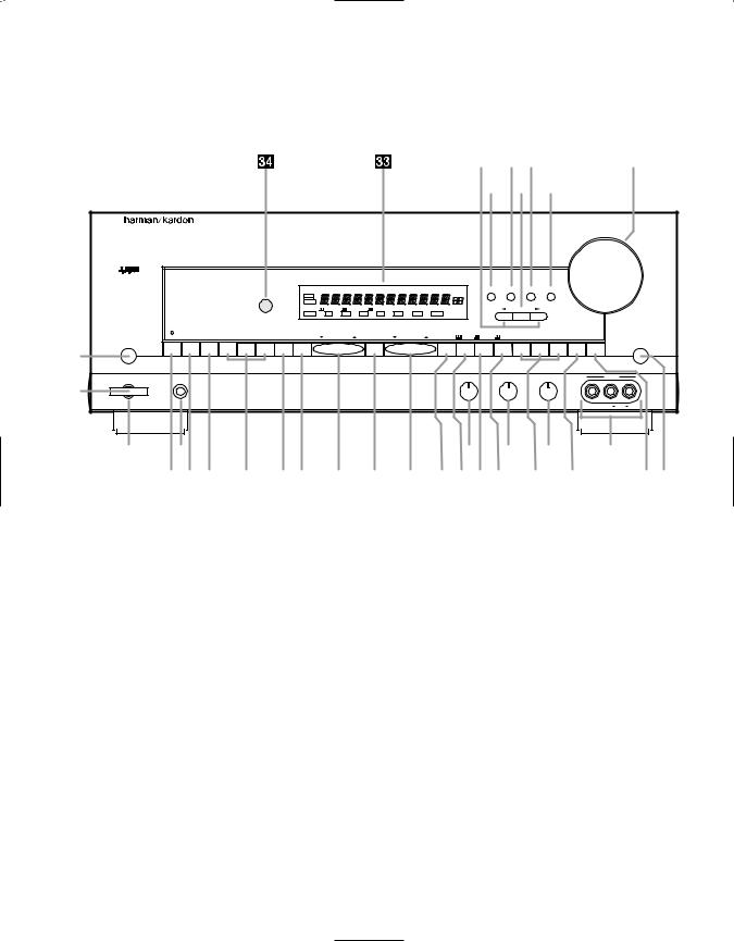
Front Panel Controls
4
¸ ¯ˆ |
Ù |
˘ ˜ ı
AVR 45
Volume
|
|
|
|
|
|
|
SLEEP |
|
|
TUNED |
MONO STEREO |
AUTO MEMORY |
PRESET |
Speaker |
Channel Dig. Select |
Delay |
|
|
|||
|
|
|
|
|
|
|
MUTE |
|
|
|
|
|
|
|
|
|
|
|
|
|
|
|
|
|
|
|
|
|
BYPASS |
|
|
|
|
|
|
|
|
|
|
|
|
|
|
|
|
|
|
|
|
|
ANALOG |
DIGITAL |
PRO LOGIC |
|
3-STEREO |
HALL 1 |
HALL 2 |
THEATER |
|
|
Set |
|
|
|
|
|
|
|
|
|
|
|
OPT |
COAX |
AC-3 |
PCM |
MULTI |
NIGHT |
DISPLAY |
|
|
|
|
|
|
|
|
TAPE |
CD |
DVD |
VID 1 |
VID 2 |
VID 3 |
6 CHANNEL |
AM/FM |
TUNNING |
|
PRESET SCAN |
PRESET |
FM MODE |
DIGITAL |
PRO LOGIC |
3-STEREO HALL 1 |
HALL 2 |
THEATER |
TEST TONE |
SURR. OFF |
||
|
|
|
|
|
|
Mute |
1 |
|
|
|
|
|
|
Power |
Phones |
Bass |
Treble |
Balance |
|
VIDEO 3 |
2 |
|
|
|
|
|
|
|
|
Min Max |
Min Max |
L R |
Video |
L Audio R |
3 |
4 |
5 |
6 |
7 |
|
8 |
|
9)! @ #$ % ^ & *(ÓÔ Ò |
|
ÚÛ |
|||
1Main Power Switch |
#6-Channel Direct Selector |
ÛMute |
2System Power Control |
$AM/FM |
ÙVolume Control |
3Power Indicator |
%Tuning Button |
ıDelay |
4Headphone Jack |
^Preset Scan |
ˆDigital Input Selector |
5Bass Control |
&Preset Stations Selector |
˜Set Button |
6Treble Control |
*FM Mode |
¯Channel Select |
7Balance Control |
(Dolby Digital Selector |
˘Speaker Select Button |
8Video 3 Inputs |
ÓDolby Pro Logic Selector |
¸Selector Buttons |
9Tape Selector |
ÔDolby 3 Stereo Selector |
33Information Display |
)CD |
Analog Surround Mode Selectors |
34Remote Sensor Window |
!DVD Input |
ÒTest Tone |
|
@Video Input Selectors |
ÚSurround Off |
|

Front Panel Controls
5
1Main Power Switch: Press this button to apply power to the AVR45. When the switch is pressed in the unit is placed in a Standby mode, as indicated by the amber LED 3surrounding the System Power control 2. This button MUST be pressed in to operate the unit. To turn the unit off and prevent the use of the remote control, this switch should be press this switch until it pops out from the front panel so that the word “OFF” may be read at the top of the switch.
NOTE: In normal operation this switch is left in the “ON” position.
2System Power Control: When the Main Power Switch 1is “ON,” press this button to turn on the AVR45; press it again to turn the unit off. Note that the Power Indicator surrounding the switch 3will turn green when the unit is on.
3Power Indicator: This LED will illuminate in amber when the unit is in the Standby mode to signal that the unit is ready to be turned on. When the unit is in operation, the indicator will turn green.
4Headphone Jack: This jack may be used to listen to the AVR45’s output through a pair of headphones.
Be certain that the headphones have a standard 1⁄4" stereo phone plug.
5Bass Control: Turn this control to modify the low-frequency output of the left/right channels by as much as ±10dB. Set this control to a suitable position for your taste and room acoustics.
6Treble Control: Turn this control to modify the high-frequency output of the left/right channels by as much as ±10dB. Set this control to a suitable position for your taste and room acoustics.
7Balance Control: Turn this control to change the relative volume for the front left/right channels.
NOTE: For proper operation of the surround modes this control should be at the midpoint, or “12 o’clock” position.
8Video 3 Inputs: These audio/video inputs may be used for temporary connectiion of video games, camcorders, digital still cameras or portable audio products. To select a source connected to these jacks, press the Vid 3 Input Selector @.
9Tape Selector: Press this button to select the device connected to the Tape Monitor jacks c as the listening source. The previously selected source will continue to show in the Information Display
33, and the red LED above the button will illuminate to remind you that you are listening to the tape monitor output.
)CD: Press this button to select the device connected to the CD Input jacks § as the listening source.
!DVD Input: Press this button to select the device connected to the DVD Play jacks ¶ as the listening and viewing source.
@Video Input Selectors: Press one of these buttons to select a source connected to the rear panel Audio/Video inputs £ fl, or the front panel Audio/Video input 8.
#6-Channel Direct Selector:
Press this button to select the output of an optional, external 6-channel decoder connected to the 6 Ch Direct inputs as the listening source.
$AM/FM: Press this button to select the tuner as the AVR45’s input source. When it is first pressed the last station tuned will be heard. Press it again to change between AM and FM bands.
%Tuning Button: Press the left side of the button to tune lower frequency stations and the right side of the button to tune higher frequency stations. When a station with a strong signal is tuned, the TUNED indicator Rwill illuminate in the Information Display 33. A brief (1/2 second) press of the button will manually tune to the next frequency increment, while pressing and holding the button for a longer period will automatically tune to the next station with a signal strong enough for acceptable reception.
^Preset Scan: Press this button to automatically scan through the stations that have been programmed in the AVR45’s memory. The tuner will play five seconds of each station before moving to the next preset station. To stop the scan when the desired station is heard, press the button again. (See page 26 for more information on the tuner memory system.)

Front Panel Controls
6
&Preset Stations Selector: Press this button to select stations that have been entered into the preset memory. (See page 26 for more information on tuner programming.)
*FM Mode: Press this button to select the stereo or mono mode for FM tuning. In the STEREO mode a Stereo indicator Pwill illuminate in the information display, and stereo reception will be provided when stations are transmitting stereo signals. In the MONO mode the left and right signals from stereo broadcasts will be mixed together and reproduced through all channels. Select MONO for better reception of weak signals.
(Dolby Digital Selector: Press this button to select the Dolby Digital surround mode when listening to a program that carries the Dolby Digital information. (See pages
22–25 for more information on surround modes and digital audio.)
ÓDolby Pro Logic Selector: Press this button to select the Dolby Pro Logic surround mode when listening to an analog program that is encoded with surround-sound information. (See pages 22–25 for more information on surround modes.)
ÔDolby 3 Stereo Selector: Press this button to select the Dolby 3 Stereo listening mode. This mode is used primarily when a program has surround information when a center channel speaker, but no surround speakers, is installed. (See pages 22–25 for more information on surround modes.)
Analog Surround Mode Selectors: Press one of these buttons to select the analog surround modes. These modes may be used with any analog program
source to create a pleasing surround effect. (See pages 22–25 for more information on surround modes.)
ÒTest Tone: Press this button to begin the sequence of steps used to set the AVR45’s output levels. When this button is pressed, a test tone will replace the currently selected listening source. (See page 19 for more information on using the test tone to set the output levels.)
ÚSurround Off: Press this button to turn off all surround processing, and to listen to a program in traditional stereo from the left front and right front speakers only.
ÛMute: Press this button to momentarily silence the speaker output of the AVR45.
ÙVolume Control: Turn the knob clockwise to increase volume, counterclockwise to decrease the volume.
ıDelay: Press this button to begin the sequence of steps required to enter delay time settings. (See page 20 for more information on delay times.)
ˆDigital Input Selector: When playing a source that has a digital output, press this button to select between the Optical · and Coaxial
° Digital inputs. (See pages 22–25 for more information on digital audio.)
˜Set Button: When making choices during the setup and configuration process, press this button to enter the desired setting, as shown in the Information Display
33, into the AVR45’s memory. (See pages 17–24 for more information on setup and configuration.)
¯Channel Select: Press this button to begin the process of selecting and configuring the AVR45’s output channels. (See pages 17–24 for more information on setup and configuration.)
˘Speaker Select Button: Press this button to begin the process of selecting the speaker positions that are used in your listening room. (See pages 17–24 for more information on setup and configuration.)
¸Selector Buttons: When you are establishing the AVR45’s configuration settings, use these buttons to select between the choices available, as shown in the Information Display 33.
33Information Display: This display delivers messages and status indications to help you operate the receiver. (See page 7 for a complete explanation of the Information Display.)
34Remote Sensor Window: The sensor behind this window receives infrared signals from the remote control. Aim the remote at this area and do not block or cover it unless an external remote sensor is installed.
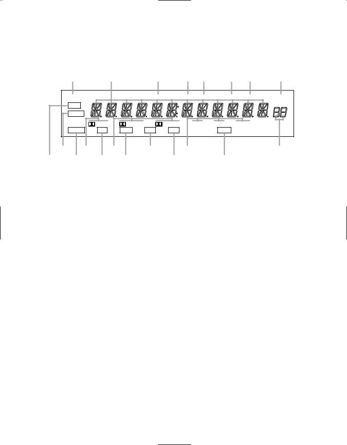
Front Panel Information Display
7
T S R Q P O N M
SLEEP |
|
|
TUNED |
MONO |
STEREO |
|
AUTO |
MEMORY |
PRESET |
|
MUTE |
|
|
|
|
|
|
|
|
|
|
BYPASS |
|
|
|
|
|
|
|
|
|
|
ANALOG |
DIGITAL |
PRO LOGIC |
|
3-STEREO |
HALL 1 |
HALL 2 |
THEATER |
|
||
OPT |
COAX |
AC-3 |
PCM |
|
|
NIGHT |
|
|
||
B |
D |
F |
H |
J |
L |
A |
C |
E G |
I |
K |
|
AMute |
|
|
HAC-3 Indicator |
|
OAuto |
BBypass |
|
|
IPCM Indicator |
|
PStereo Indicator |
CAnalog |
|
|
JAnalog Surround Mode Indicators |
QMono Indicator |
|
DDolby Digital Indicator |
|
KNight Indicator |
|
RTuned Indicator |
|
EOptical Source |
|
LPreset Number |
SMain Information Display |
||
FAnalog Dolby Surround Mode Indicators |
MPreset Indicator |
TSleep Indicator |
|||
GCoax Source |
|
|
NMemory |
|
|
Front Panel Information Display
8
AMute: This indicator illuminates to remind you that the AVR45’s output has been silenced by pressing the Mute button Ûd. Press the Mute button again to return to the previously selected output level.
BBypass: This indicator illuminates when the surround processing has been disabled by pressing the Surround Off button Ú. When this indicator is lit, the AVR45 will play traditional stereo sound using the front left and front right speakers only.
CAnalog: This indicator illuminates when an analog input source is in use.
DDolby Digital Indicator: This indicator illuminates when a Dolby Digital source is being played.
EOptical Source: This indicator illuminates when a digital source is in use via a connection to the
Optical Digital input ·.
FAnalog Dolby Surround Mode Indicators: These indicators illuminate when one of the analog (matrix) Dolby Surround modes is in use.
GCoax Source: This indicator illuminates when a digital source is in use via a connection to the Coaxial Digital input °.
HAC-3* Indicator: This indicator illuminates when the AVR45 is decoding a Dolby Digital input source.
IPCM Indicator: This indicator illuminates to show that a standard PCM (SP/DIF) digital audio signal is being decoded by the digital-to- analog converter.
JAnalog Surround Mode Indicators: These indicators illuminate when one of the DSP generated analog surround modes is in use with an analog input source.
KNight Indicator: This indicator lights when the AVR45 is in the Night mode, which prevents the AVR45 from loud playback when digital sources are in use.
LPreset Number: This two-digit display indicates the station preset number that is currently in use, or that is being entered.
MPreset Indicator: This indicator illuminates when one of the stations entered into the preset memory is tuned. The number that appears below the indicator is the preset station’s memory.
NMemory: This indicator flashes when entering presets and other information into the tuner’s memory.
OAuto: This indicator illuminates when the “Auto” mode is in use for FM tuning.
PStereo Indicator: This indicator illuminates when an FM station is being tuned in stereo.
QMono Indicator: This indicator illuminates when the tuner has been placed in the monaural mode by pressing the FM Mode button *. Set the tuner for mono listening to cut noise and improve the quality of distant stereo signals.
RTuned Indicator: This indicator illuminates when a station is being received with sufficient signal strength to allow for acceptable listening quality.
SMain Information Display: This display shows messages relating to the status, input source, surround mode, tuner, volume level or other aspects of unit’s operation.
TSleep Indicator: This indicator is illuminated when the Sleep function is in use. The number that appears above the indicator is the number of minutes remaining before the AVR45 will return to the Standby mode.
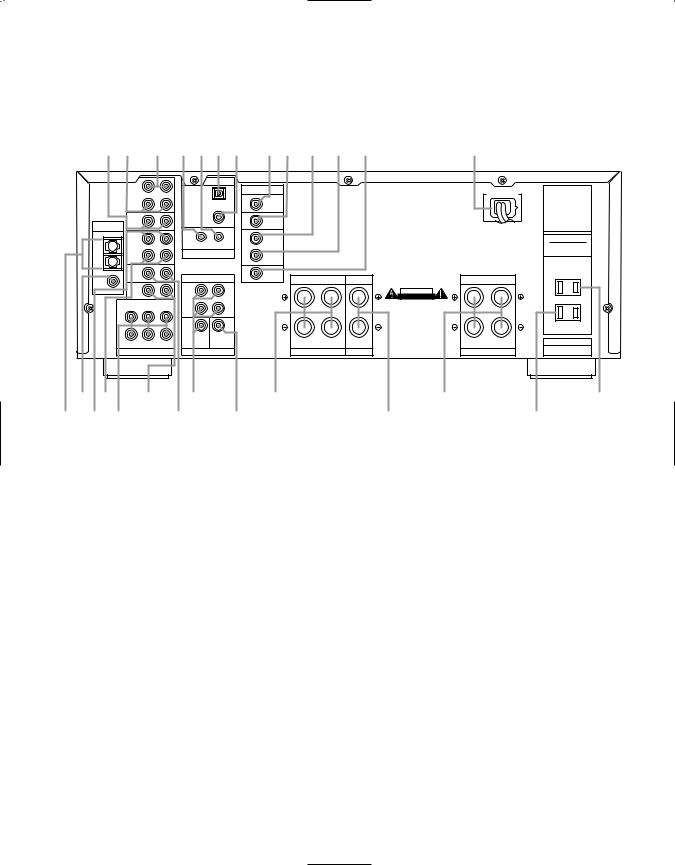
Rear Panel Connections
9
fl d c b a · ° ‡fl £ ¢ ¶ |
fi |
|
IN |
|
|
|
DIGITAL INPUT |
|
|
|
|
|
|
|
|
|
VIDEO |
|
|
MODEL NO. AVR-45 |
|
|
TAPE |
|
|
OPTICAL |
|
|
AC 120V 60 Hz |
||
|
MONITOR |
|
|
|
|
TV |
|
|
HARMAN KARDON |
|
OUT |
|
|
|
|
MONITOR |
|
|
|
|
|
|
|
|
|
OUT |
|
|
NORTHRIDGE |
|
|
|
|
COAXIAL |
|
|
|
|
|
|
VIDEO |
|
|
|
VIDEO 2 |
|
|
CALIFORNIA, USA |
|
ANTENNA |
2 |
|
|
|
|
|
|
|
|
|
|
|
|
|
|
|
MADE IN CHINA |
||
|
|
|
|
|
|
|
|
||
|
PLAY |
|
|
|
|
IN |
|
|
AC OUTLETS |
|
IN |
|
|
|
|
|
|
||
AM |
VIDEO |
|
|
OUT |
IN |
VIDEO 1 |
|
|
(120V.60Hz) |
|
1 |
|
|
|
|
|
|
TOTAL 150W MAX |
|
|
|
|
REMOTE CONTROL |
|
|
|
|||
|
REC |
|
|
OUT |
|
|
|
||
GND |
OUT |
|
|
|
|
|
|
|
|
|
|
|
|
|
|
|
|
||
|
DVD |
|
|
|
|
DVD |
|
|
SWITCHED |
FM |
|
|
PRE OUT |
CENTER |
|
TOTAL 50W MAX. |
|||
|
|
|
FRONT |
SURROUND |
|
||||
(75Ω ) |
|
|
|
|
|
|
|
|
|
|
CD |
|
|
FRONT |
|
|
|
CAUTION |
|
|
|
|
|
|
|
|
|
RISK OF ELECTRIC SHOCK |
|
|
|
|
|
|
|
|
|
DO NOT OPEN |
|
|
|
|
|
|
|
|
|
AVIS: RISQUE DE CHOC |
|
|
CENTER |
SL |
FL |
SURR. |
|
|
|
ELECTRIQUE - NE PAS OUVRIR |
|
|
|
|
|
|
|
||||
|
|
|
|
|
|
|
|
|
|
|
|
|
|
|
|
UNSWITCHED |
|
|
|
|
|
|
TOTAL 100W MAX. |
|
CENTER SUB WOOFER |
|
|
RIGHT |
LEFT |
SERIAL NO. |
SUB WOOFER SR |
RIGHT |
LEFT |
CENTER |
|||
FR |
|
|
|
|
|
|
6 CH. DIRECT |
SPEAKERS 8 Ohms |
SPEAKER 8 Ohm |
SPEAKERS 8 Ohms |
|
||
™ ¢ § |
• |
‚ |
|
l¤ |
› |
¡ £ |
¶ |
ª |
⁄ |
‹ |
|
¡ AM Antenna |
|
|
ª Subwoofer Pre-Out |
‡ TV Monitor Video Output |
|
™ FM Antenna |
|
|
‚ Front |
° AC-3/PCM Coaxial Input |
|
£ Video 1 Inputs |
|
|
⁄ Center |
· AC-3/PCM Optical Input |
|
¢ Video 1 Outputs |
|
|
lSurround |
a Remote IR In |
|
6-Channel Direct Inputs |
|
‹ Unswitched AC Outlet |
b Remote IR Out |
||
§ CD Inputs |
|
|
› Switched AC Outlet |
c Tape Monitor In |
|
¶ DVD Inputs |
|
|
fi Power Cable |
d Tape Monitor Out |
|
• Pre-Outs |
|
|
fl Video 2 Inputs |
|
|
¡ AM Antenna: Connect the AM loop antenna supplied with the receiver to these terminals. If an external AM antenna is used, make connections to the AM and GND terminals in accordance with the instructions supplied with the antenna.
™ FM Antenna: Connect an indoor or external FM antenna to this terminal.
£Video 1 Inputs: Connect these jacks to the audio and video PLAY/OUT jacks of a VCR.
¢Video Outputs 1: Connect these jacks to the audio and video RECORD/IN jacks of a VCR.
6-Channel Direct Inputs: If an external digital audio decoder is used for 5.1 (Dolby AC-3) audio, connect the outputs of that decoder to these terminals.
§ CD Inputs: Connect these jacks to the output of a compact disc player or CD changer.
¶ DVD Inputs: Connect the analog audio outputs and composite video output of a DVD or LV player to these jacks.
• Pre-Outs: If external power amplifiers are used for any channels, connect them to these jacks.

Rear Panel Connections
10
ª Subwoofer Pre-Out: Connect this jack to the line level input of a powered subwoofer. If an external subwoofer amplifier is used, connect this jack to the subwoofer amplifier input.
‚ Front: Connect these terminals to the front left/right speakers.
⁄ Center: Connect these terminals to the center speaker.
lSurround: Connect these terminals to the surround speakers.
‹ Unswitched AC Outlet: This outlet may be used to power any AC device. The power will remain on at this outlet regardless of whether the AVR45 is on or off.
NOTE: The power consumption of the device plugged into each of these outlets should not exceed 100 watts.
› Switched AC Outlet: This outlet may be used to power any device that you wish to have turn on when the unit is turned on with the System Power Control switch 2.
fi Power Cable: Connect the AC plug to a non-switched AC wall output
flVideo 2 Inputs: Connect these jacks to the audio and video outputs of a TV Tuner, Cable TV converter box, satellite receiver or any other audio/video source.
‡TV Monitor Video Output:
Connect this jack to the standard (composite) video input of a TV monitor or video projector to view the on-screen menus and the output of any standard video source selected by the receiver’s video switcher.
° AC-3/PCM Coaxial Input:
Connect the coax digital output from a DVD player, HDTV receiver, LV player or CD player to this jack. The signal may be either a Dolby Digital (AC-3) signal or a standard PCM digital source.
· AC-3/PCM Optical Input:
Connect the optical digital output from a DVD player, HDTV receiver, LV player or CD player to this jack. The signal may be either a Dolby Digital (AC-3) signal or a standard PCM digital source.
a Remote IR In: If the AVR45’s front panel IR sensor is blocked due to cabinet doors or other obstructions, an external IR sensor may be used. Connect the output of the sensor to this jack.
b Remote IR Out: This connection permits the IR sensor in the receiver to serve other remote controlled devices. Connect this jack to the “IR IN” jack on Harman Kardon or other compatible equipment.
cTape Monitor In: Connect these jacks to the PLAY/OUT jacks of an audio recorder.
dTape Monitor Out: Connect these jacks to the RECORD/INPUT jacks of an audio recorder.

Remote Control Functions
11
a
b
c `
d


 z
z
e y
f |
x |
g |
|
h |
w |
i |
|
j |
v |

 u
u
k


 t
t
s
l
m


 r n
r n


 q
q
o
 p
p
aAVR Selector
bDevice Control Selectors
cPower Button
dMute
eTest
fDisplay/Multiroom
g⁄/¤ Buttons
h‹/Channel Button
iSet Button
jNight Mode
k Source Selectors
l Numeric Keys
mDirect/Enter
nMemory Button
oInfo Button
pLight Button
qTuner Mode
rClear Button
sPreset Up/Down
tTuning Up/Down
uTransport Controls
vDelay/Prev Ch.
w›/Digital Button
xSpeaker Configuration
ySurround Mode Selector
zVolume
`Sleep Button

Remote Control Functions
12
IMPORTANT NOTE: The AVR45’s remote may be programmed to control up to eight devices, including the AVR45. Before using the remote, it is important to remember to press the Device Control Selector button abthat corresponds to the unit you wish to operate. In addition, the AVR45’s remote is shipped from
the factory to operate the AVR45 and Harman Kardon CD players and cassette decks. The remote is also capable of operating a wide variety of other products using the control codes that are part of the remote. Before using the remote with other products, follow the instructions on pages 28–29 to program the proper codes for the products in your system.
It is also important to remember that many of the buttons on the remote take on different functions, depending on the product selected using the Device Control Selectors. The descriptions shown here primarily detail the functions of the remote when it is used to operate the AVR45. (See pages 28–31 for information about alternate functions for the remote’s buttons.)
aAVR Selector: Press this button to use the remote control for operation of the AVR45. Note that the button will briefly turn red after it has been pressed to confirm your selection.
bDevice Control Selectors:
Press one of these buttons to use the remote to control the functions of another audio/video device. Note that the button will briefly turn red after it has been pressed to confirm your selection. (See pages 28–29 for information on programming the AVR45’s remote to operate these devices.)
cPower Button: Press this button to turn the currently selected device on or off.
dMute: Press this button to momentarily silence the AVR45 or TV set being controlled, depending on which device has been selected.
When the AVR45 remote is being programmed to operate another device, this button is pressed with the Device Control Selector button bto begin the programming process. (See page 28 for more information on programming the remote.)
eTest: Press this button to begin the sequence used to calibrate the AVR45’s output levels. (See page 19 for more information on calibrating the AVR45.)
fDisplay/Multiroom Button:
This button does not function with the AVR45, but it is available for use with other devices.
g⁄/ ¤ Buttons: These are multipurpose buttons. They will be used most frequently to select a surround mode. To change the surround mode, first press the SURR/CH¤ button y. Next press these buttons to scroll up or down through the list of surround modes that appear in the
Information Display 33. (See page 24 for more information.) These buttons are also used to increase or decrease output levels used to
lower the AVR45’s output levels when configuring the unit with either the internal test tone or and external source. (See pages 19 and 26 for more information.) They are also used to enter delay time settings after the Delay button vhas been pressed. (See page 20 for more information.)
h‹/Channel Button: This button is used to start the process of
setting the AVR45’s output levels to an external source. Once this button is pressed, use the ⁄/ ¤ buttons gto select the channel being adjusted, then press the Set button i, followed by the ⁄/ ¤ buttons again to change the level letting. (See page 27 for more information.)
iSet Button: This button is used to enter settings into the AVR45’s memory. It is also used in the setup procedures for delay time, speaker configuration and channel output level adjustment. (See pages 17–21 for complete information.)
jNight Mode: Press this button to activate the “Night” mode, preventing loud playback when the digital modes are in use without altering the dynamic range of the output signal.
When the AVR45 remote is being programmed to operate other devices, this button is pressed to begin a readout of a programmed code. (See page 28 for more information.)
kSource Selectors: Press these buttons to select an input source for the AVR45. The AM/FM button is also used to switch between frequency bands when the tuner is in use.
NOTE: Pressing one of these buttons selects the source only. In order to control the actual source machine using the remote you must press the
Device Control Selector button b for the desired product.
lNumeric Keys: These buttons serve as a ten-button numeric keypad to enter tuner preset positions. They are also to be used to select channel numbers when TV has been selected on the remote, or to select track numbers on a CD, DVD or LD player, depending on how the remote has been programmed.
NOTE: The 0 button has a dual function. It also serves as the CLEAR button for use in programming the tuner or clearing the system memory.
mDirect /Enter: Press this button to select a radio station by entering its frequency using the Numeric Keys l. (See page 26 for more information.)
Remote Control Functions
13
nMemory Button: Press this button to enter a radio station into the AVR45’s preset memory. After pressing the button the MEMORY indicator Nwill flash, and you then have five seconds to enter a present memory location using the Numeric Keys l. (See page 26 for more information.)
NOTE: Although the word “Sleep” appears above this button, it refers to control of devices other than the AVR45. Use the Sleep button `to control the AVR45’s Sleep function.
oInfo Button: This button does not function with the AVR45, but it is available for use with other devices.
pLight Button: Press this button to activate the remote’s built-in backlight for better legibility of the buttons in a darkened room.
qTuner Mode: Press this button when the tuner is in use to select between automatic tuning and manual tuning. When the button is pressed so that the AUTO indicator Ogoes out, pressing the Tuning buttons twill move the frequency up or down in single-step increments. When the FM band is in use, pressing this button when a station’s signal is weak will change to monaural reception, as indicated
by the MONO indicator Q. (See page 26 for more information.)
rClear Button: This button does not function with the AVR45, but it is available for use with other devices.
sPreset Up/Down: When the tuner is in use, these buttons scroll through the stations that have been programmed into the AVR45’s memory. When many source devices, such as CD players, VCRs and cassette decks, are selected using the
Device Control Selectors b, these buttons will normally function as chapter step or track advance.
tTuning Up/Down: When the tuner is in use, these buttons will tune up or down through the selected frequency band. If the Tuner Mode button qhas been pressed so that the AUTO indicator Ois illuminated, pressing these buttons will cause the tuner to seek the next station with acceptable signal strength for quality reception. When the AUTO indicator Ois NOT illuminated, pressing these buttons will tune stations in single-step increments. (See page 26 for more information.)
uTransport Controls: These controls do not control any functions of the AVR45, but they are used extensively when operating a wide variety of CD players, cassette decks and VCRs. (See page 28 for information on programming the remote to utilize these buttons.)
vDelay/Prev Ch.: Press this button to begin the process for setting the delay times used by the AVR45 when processing surround sound. After pressing this button the delay times are entered by pressing the Set button i, and then using the ⁄/ ¤ buttons gto change the setting. Press the Set button again to complete the process. (See page 20 for more information.)
w›/Digital Button: This button is used to select the type of digital input used with any one of the input sources connected to the AVR45. After pressing this button, use the ⁄/ ¤ buttons gto make your selection between
OPTICAL Eor COAXIAL Gdigital. Press the Set button ito enter your choice. (See page 24 for more information.)
xSpeaker Configuration: Press this button to begin the process of configuring the AVR45’s Bass Management System for use with the type of speakers used in your system. Once the button has been pressed, use the ⁄/ ¤ buttons gto
select the channel you wish to set up. Press the Set button i, and then select another channel to configure. When all adjustments have been completed, press the Set button twice to exit the settings and return to normal operation. (See page 17 for more information.)
ySurround Mode Selector: Press this button to begin the process of changing the surround mode. After the button has been pressed, use the ⁄/ ¤ buttons gto select the desired surround mode. (See page 24 for more information.) Note that this button is also used to tune channels when the TV is selected using the
Device Control Selector b.
When the AVR45 remote is being programmed for the codes of another device, this button is also used in the “Auto Search” process. (See page 28 for more information on programming the AVR45 remote.)
zVolume: Press these buttons to raise or lower the system volume.
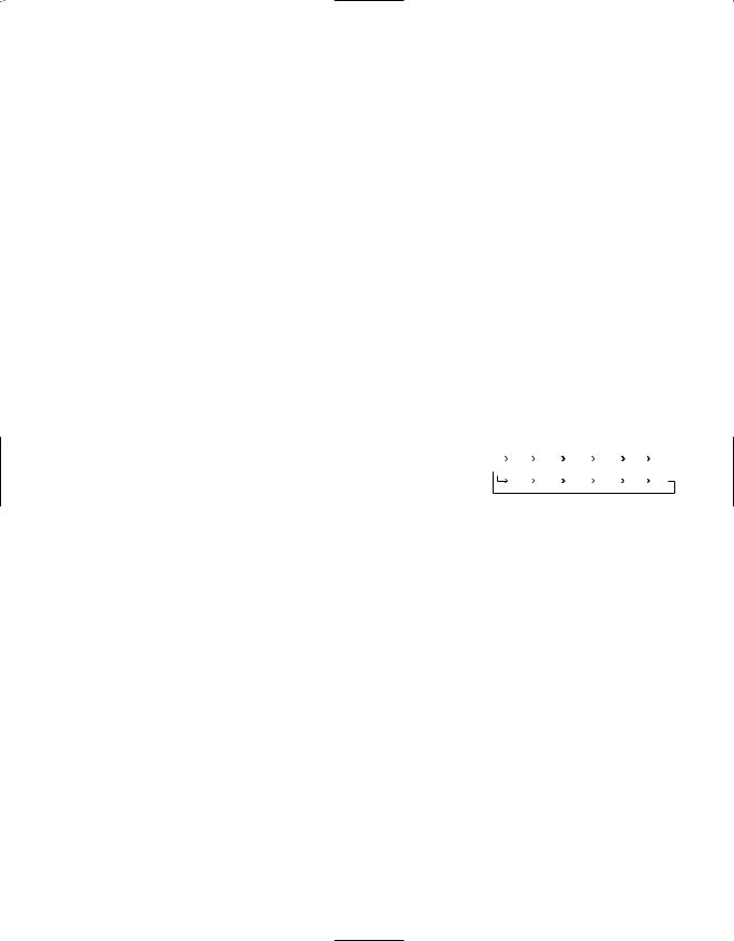
`Sleep Button: Press this button to place the unit in the Sleep mode. After the time shown in the display, the AVR45 will automatically go into the Standby mode. Each press of the button changes the time until turn-off in the following order:
|
|
|
90 |
|
|
|
80 |
|
|
|
70 |
|
|
|
60 |
|
|
|
50 |
|
|
40 |
|
|
|
|
min |
|
|
min |
|
|
min |
|
|
min |
|
|
min |
|
min |
|
|||||
|
|
|
|
|
|
|
|
|
|
|
|
|
|
|
|
|
|
|
|
|
|
|
|
|
|
30 |
|
|
20 |
|
|
10 |
|
|
5 |
|
|
1 |
|
|
OFF |
||||||
|
|
|
min |
|
|
min |
|
|
min |
|
|
min |
|
|
min |
|
|||||||
|
|
|
|
|
|
|
|
|
|
|
|
|
|
||||||||||
Note that this button is also used to change channels on your TV when the TV is selected using the
Device Control Selector b.
When the AVR45 remote is being programmed for the codes of another device, this button is also used in the “Auto Search” process. (See page 28 for more information on programming the AVR45 remote.)

Installation and Connections
14
System Installation
After unpacking the unit, and placing it on a solid surface capable of supporting its weight, you will need to make the connections to your audio and video equipment. These steps need to be done only when the receiver is first installed, or when a change is made to the input source equipment.
Audio Equipment Connections
We recommend that you use high-quality interconnect cables when making connections to source equipment and recorders to preserve the quality of the signals.
When making connections to audio source equipment or speakers it is always a good practice to unplug the unit from the AC wall outlet. This prevents any possibility of accidentally sending audio or transient signals to the speakers that may damage them.
1. Connect the analog output of a CD player to the CD inputs §.
NOTE: When the CD player has both fixed and variable audio outputs it is best to use the fixed output unless you find that the input to the receiver is so low that the sound is noisy, or high that the signal is distorted.
2. Connect the Play/Out jacks of a cassette deck, MD or other audio recorder to the Tape Monitor In jacks c. Connect the Record/In jacks on the recorder to the Tape Monitor Out jacks d on the AVR45.
3.Connect the output of any digital sources to be used to the appropriate connections on the AVR45 rear panel. Note that the Optical and Coaxial digital inputs · ° may be used with either a Dolby Digital (AC-3) source or the output of a conventional CD or LV player’s PCM (SP/DIF) output.
4.Assemble the AM Loop Antenna supplied with the unit as shown below. Connect it to the AM and GND screw terminals ¡.
5.Connect an FM antenna to the FM (75 ohm) connection ™. The FM antenna may be an external roof
antenna, an inside powered or wire lead antenna or a connection from a cable TV system. Note that if the antenna or connection uses 300-ohm twin-lead cable, you must use the 300-ohm-to- 75-ohm adapter supplied with the unit to make the connection.
6.Connect the front, center and surround speaker outputs ‚ ⁄ l to the respective speakers.
To assure that all the audio signals are carried to your speakers without loss of clarity or resolution, we suggest that you use high-quality speaker cable. Many brands of cable are available, and the choice of cable may be influenced by the distance between your speakers and this receiver, the type of speakers you use, personal preferences and other factors.
Your dealer or installer is a valuable resource to consult in selecting the proper cable.
Regardless of the brand of cable selected, we recommend that you use a cable constructed of fine, multistrand copper with a gauge of 14 or smaller. Remember that in specifying cable, the lower the number, the thicker the cable.
Cable with a gauge of 16 may be used for short runs of less than ten feet. We do not recommend that you use cables with an AWG equivalent of 18 or higher due to the power loss and degradation in performance that will occur.
Cables that are run inside walls should have the appropriate markings to indicate listing with UL, CSA or other appropriate testing agency standards. Questions about running cables inside walls should be referred to your installer or a licensed electrical contractor who is familiar with the NEC and/or the applicable local building codes in your area.
When connecting wires to the speakers, be certain to observe proper polarity. Remember to connect the “negative” or “black” wire to the same terminal on the receiver and the speaker. Similarly, the “positive” or “red” wire should be connected to the like terminal on the AVR45 and speaker.
We also recommend that the length of cable used to connect speaker pairs be identical. For example, use the same length piece of cable to connect the front left and front right or surround left and surround right speakers, even if the speakers are a different distance from the AVR45.

Installation and Connections
15
NOTE: While most speaker manufacturers adhere to an industry convention of using black terminals for negative and red ones for positive, some manufacturers may vary from this configuration. To assure proper phase, and optimal performance, consult the identification plate on your speaker, or the speaker’s manual to verify polarity. If you do not know the polarity of your speaker, ask your dealer for
advice before proceeding, or consult the speaker’s manufacturer.
7. Connections to a subwoofer are made via a line level audio connection from the Subwoofer Output ª to the line level input of a subwoofer with a built-in amplifier. If a passive subwoofer is used, the connection first goes to a power amplifier, which will be connected to one or more subwoofer speakers.
Video Equipment Connections
Video equipment is connected in a fashion similar to audio components. Again, the use of high-quality interconnect cables is recommended to preserve signal quality.
1. Connect a VCR’s audio and video Play/Out jacks to the Video 1 In jacks £ on the rear panel. The audio and Record/Out jacks on the VCR should be connected to the Video 1 Out jacks ¢ on the AVR45.
2.Connect the audio and video outputs of a satellite receiver, cable TV converter or television set or any other video source to the Video 2 In jacks fl.
3.Connect the audio and video outputs of a DVD or laser disc player to the DVD jacks ¶.
4.Connect the TV Monitor Out ‡ jacks on the receiver to the video input of your television monitor or video projector.
System and Power Connections
The AVR45 is designed for flexible use with external control components and power amplifiers. These connections are easy to make during an initial installation, or at a later date should you choose to upgrade your system.
Remote Control Extension
If the receiver is placed behind a solid or smoked glass cabinet door, the obstruction may prevent the remote sensor from receiving commands. In this event, an optional remote sensor may be used. Connect the output of the remote sensor to the Remote Cont. In jack a.
If other components are also prevented from receiving remote commands, only one sensor is needed. They may use this unit’s sensor or a remote eye by running a connection from the Remote Cont. Out jack b to the Remote In jack on Harman Kardon or other compatible equipment.
External Audio Power Amplifier Connections
If desired, optional external power audio power amplifiers may be used with the AVR45. Connections to these amplifiers are made by using audio interconnect cables connected to both the Preamp Outputs • on the rear panel and
the audio input jacks of the external amplifiers.
External Audio Decoder Connection
To provide for the ultimate flexibility, the AVR45 may be used in conjunction with optional, external decoders for digital audio systems other than the AVR45’s own built-in Dolby Digital system. If an external decoder is used, connect the output jacks of the decoder to the 6-Channel Direct inputs , making sure to match channels.
These jacks may also be used for connections to devices usch as DVD players or High Definition Television (HDTV) sets or decoders that feature built-in digital surround decoders. Although the digital decoding system in the AVR45 will typically provide audio performance that is superior to other decoders, you may use these jacks to provide an additional 6-channel input for connection to a DVD player or HDTV set with a built-in decoder and discrete 6-channel analog outputs.
AC Power Connections
This unit is equipped with two accessory AC outlets. They may be used to power accessory devices, but they should not be used with high-current draw equipment such as power amplifiers. The total power draw may not exceed 50W to each outlet.
The Switched › outlet will receive power only when the unit is on. This is recommended for devices that have no power switch, or a mechanical power switch that may be left in the “ON” position.
NOTE: Devices with electronic power switches may only go into a Standby mode when plugged in here.
The Unswitched ‹ outlet will receive power as long as the unit is plugged into a powered AC outlet.
Finally, when all connections are complete, plug the power cord into a nonswitched 120-volt AC wall outlet. You’re almost ready to enjoy the AVR45!
System Configuration
16
When all audio, video and system connections have been made, there are a few configuration adjustments to be made. A few minutes spent to correctly configure and calibrate the unit will greatly add to your listening experience.
Speaker Selection and Placement
The placement of speakers in a multi- channel-home-theater system can have a noticeable impact on the quality of sound reproduced.
No matter which type or brand of speakers is used, the same model or brand of speaker should be used for the front left, center and right speakers. This creates a seamless front soundstage, and eliminates the possibility of distracting sonic disturbances that occur when a sound moves across mismatched front channel speakers.
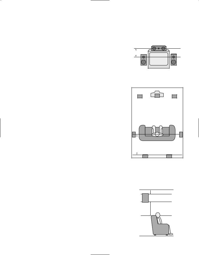
Speaker Placement
Depending on the type of center channel speaker in use and your viewing device, place the center speaker directly above or below your TV or in the center behind a perforated front projection screen.
Once the center channel speaker is installed, position the left and right front speakers so that they are as far away from one another as the center channel speaker is from the preferred listening position. Ideally, the front channel speakers should be placed so that their tweeters are no more than 24" off center from the tweeter in the center channel speaker.
Depending on the specifics of your room acoustics and the type of speakers in use, you may find that imaging is improved by moving the front left and right speakers slightly forward of the center channel
speaker. If possible, adjust all front loudspeakers so that they are aimed at ear height when you are seated in the listening position.
Using these guidelines, you’ll find that it takes some experimentation to find the correct location for the front speakers in your particular installation. Don’t be afraid to move things around until the system sounds correct. Optimize your speakers so that pans across the front of the room sound smooth, and that sounds from all speakers appear to arrive at the listening position at the same time without delay from the center speaker as opposed to the left and right speakers.
Surround speakers should be placed on the side walls of the room, at or slightly behind the listening position. The center of the speaker should face into the room. The speakers should be located so that the bottom of the cabinet is at least two feet higher than the listeners’ ears when seated in the desired area.
If side wall mounting is not practical, the speakers may be placed on a rear wall, behind the listening position. Again, they should be located so that the bottom of the cabinet is at least two feet higher than the listeners’ ears. The speakers should be no more than six feet behind the rear of the seating area.
Center Front Speaker
No more than 24" 
Left Front |
Right Front |
Speaker |
Speaker |
A) Front Channel Speaker Installation with Direct-View TV Sets or Rear-Screen Projectors
|
|
TV or Projection Screen |
|
|
Left Front |
Center Front |
Right Front |
|
Speaker |
||
|
Speaker |
Speaker |
|
|
|
||
No more than 6 feet |
when rear-mounted speakers are used |
Optional Rear Wall Mounting |
|
|
|
|
B) The distance between the left and right speakers should be equal to the distance from the seating position to the viewing screen. You may also experiment with placing the left and right speakers slightly forward of the center speaker.
Subwoofers produce non-directional sound, so they may be placed almost anywhere in a room. Subwoofer placement is highly influenced by room size and shape, and the type of subwoofer used. Follow the instructions of the subwoofer’s manufacturer, or experiment with the best location for a subwoofer in your listening room.
At least 6 inches from ceiling
At least 2 feet

System Configuration
17
System Setup
Once the speakers have been placed in the room and connected, the final step in the setup process is to enter the settings that configure the AVR45’s bass management system for the type of speakers used in your system, the calibration of the output levels and the delay times used by the surround sound processor. Before proceeding further, this is a good time to review the installation section of the manual to make certain that all connections are properly made.
You are now ready to power up the AVR45 to begin these final adjustments.
1.Plug the Power Cable fl to an unswitched AC outlet.
2.Press the Main Power Switch 1 in so that it latches in with the “OFF” wording on the top of the switch inside the front panel. Note that the
Power Indicator 3 will turn amber, indicating that the unit is in the Standby mode.
3.Install the four supplied AAA batteries in the remote as shown. Be certain to observe the (+) and (–) polarity indicators shown in the bottom of the battery compartment.
4.Turn the AVR45 on either by pressing the System Power Control 3on the front panel, or via the remote by first pressing the AVR Selector a, and then pressing the Power button
c. The Power Indicator 3will turn green to confirm that the unit is on, and the Information Display ˝ will also light up.
Speaker Configuration
The first few adjustments tell the AVR45, which type of speakers are in use. This is important as it adjusts the settings that determine which speakers receive lowfrequency (bass) information. For each of these settings use the LARGE setting if the speakers for a particular position are traditional full-range loudspeakers that are capable of reproducing sounds below 100Hz. Use the SMALL setting for smaller, frequency-limited satellite speakers that do not reproduce sounds below 100Hz. Note that when “small” speakers are used, a subwoofer is required to reproduce low-frequency sounds. Remember that the “large” and “small” descriptions do not refer to the actual physical size of the speakers, but their ability to reproduce low-frequency sounds. If you are in doubt as to which category describes your speakers, consult
the specifications in the speakers’ owner’s manual, or ask your dealer.
With the AVR45 turned on, follow these steps to configure the speakers:
1.Put the AVR45 in the Dolby Pro Logic mode by pressing the Dolby Pro
Logic Selector Ó on the front panel or by pressing the Surround Mode Selector yon the remote, followed by the ⁄/ ¤ buttons g until PRO LOGIC appears in the
Main Information Display S and the PRO LOGIC indicator F lights.
2.Press the Speaker button x˘on the remote or front panel. The words FRNT SPEAKER will appear in the
Main Information Display S.
3.Press the Set button i˜.
4.Press the ⁄/ ¤ buttons gon the
remote or the Selector buttons ¸ on the front panel until either LARGE or SMALL appears to match the type of speakers you have at the left front and right front positions, as described by the definitions shown below.
When SMALL is selected, lowfrequency sounds will be sent to the subwoofer output only. Note that if you choose this option, and there is no subwoofer connected, you will not hear any low-frequency sounds from the front channels.
System Configuration
18
When LARGE is selected, a fullrange output will be sent to the front left and right outputs, and NO low-frequency signals will be sent to the subwoofer output.
5.When you have completed your selection for the front channel, press the Set button i˜, and then press the ⁄/ ¤ buttons gon the remote or the Selector buttons ¸ on the front panel to change the display to CEN SPEAKER.
6.Press the Set button i˜again, and use the ⁄/ ¤ buttons gon the remote, or the Selector buttons ¸on the front panel, to select the option that best describes your system based on the speaker definitions shown above.
When CEN SP SMALL is selected, low-frequency center channel sounds will be sent to the subwoofer output only. Note that if you choose this option and there is no subwoofer connected, you will not hear any low-frequency sounds from the center channel speaker.
When CEN SP LARGE is selected, a full-range output will be sent to the center speaker output, and NO center channel signal will be sent to the subwoofer output.
When CEN SP NONE is selected, no signals will be sent to the center channel output. The receiver will operate in a “phantom” center channel mode and center channel information will be sent to the left and right front channel outputs.
7.When you have completed your selection for the center channel, press the Set button i˜, and then press the ⁄/ ¤ buttons gon the remote or the Selector buttons ¸ on the front panel to change the display to SUR SPEAKER.
8.Press the Set button i˜again, and then use the ⁄/ ¤ buttons g on the remote or the Selector buttons ¸on the front panel to select the option that best describes your system based on the speaker definitions shown above.
When SUR SP SMALL is selected, low-frequency surround channel sounds will be sent to the subwoofer output only. Note that if you choose this option and there is no subwoofer connected, you will not hear any low-frequency sounds from the surround speaker.
When SUR SP LARGEis selected, a full-range output will be sent to the surround channel outputs, and NO surround channel signals will be sent to the subwoofer output.
When SUR SP NONEis selected, surround sound information will be split between the front left and front right outputs. Note that for optimal performance when no surround speakers are in use, the Dolby 3 Stereo mode should be used instead of Dolby Pro Logic.
9.When you have completed your selection for the surround channel, press the Set button i˜, and then press the ⁄/ ¤ buttons gon
the remote or the Selector buttons ¸ on the front panel to change the display to S–W SPEAKER.
10.Press the Set button i˜, and then press the ⁄/ ¤ buttons gon
the remote or the Selector buttons ¸ on the front panel to select the option that best describes your system.
Select S-W SP ON if a subwoofer is connected to your system.
Select S-W SP OFF if a subwoofer is NOT connected to your system. Note that when no subwoofer is selected, low-frequency sounds below 100Hz will be sent to the front left/right speakers, provided that the selection in step 4, above, has been set to LARGE. Otherwise, no low-frequency sounds will be heard. This option is not available when the front, center or surround speakers are set to SMALL.

System Configuration
19
11.When all speaker selections have been made, press the Set button i ˜to return to normal operation.
Output Level Adjustment
Output level adjustment is a key part of the configuration process for any surround sound product. It is particularly important for a Dolby Digital receiver such as the AVR45, as correct outputs will ensure that you hear sound tracks in their proper place with the proper intensity.
IMPORTANT NOTE: Many listeners are often confused about the operation of the surround channels. While some assume that sound should always be coming from each speaker, most of the time there will be little or no sound in the surround channels. This is because they are only used when a movie director or sound mixer specifically places sound there to create ambiance, an effect or to continue action from the front of the room to the rear. When the output levels are properly set it is normal for rear/ surround speakers to operate only occasionally. Artificially increasing the volume to the rear speakers may destroy the illusion of an enveloping sound field that duplicates the way you hear sound in a movie theater or concert hall.
Before beginning the adjustment process make certain that all speaker connections have been properly made. The system volume should be set to the level that you will use during a typical listening session. Finally, make certain that the Balance Control 7is set to the center “12 o’clock” position.
To adjust and calibrate the output levels, follow these steps. For accurate calibration, it is a good idea to make these adjustments from the location in your room that is your favorite listening position:
1.Put the AVR45 in the Dolby Pro Logic mode by pressing the Dolby Pro
Logic Selector Ó on the front panel or by pressing the Surround Mode Selector yon the remote, followed by the ⁄/ ¤ buttons g until PRO LOGIC appears in the
Main Information Display S and the PRO LOGIC indicator F lights.
2.Press the Test Tone button eÒ on the remote or front panel. The
words T -T FL 0dB will appear in the Main Information Display
S, and the letters FL will flash once each second.
3.At this point, the test noise will begin to circulate among all the speakers in a clockwise rotation.
NOTE: This is a good time to verify that the speakers have been properly connected. As the test noise circulates, listen to make certain that the sound comes from the speaker position shown in the Main Information Display. If the sound from a speaker location does NOT match the position indicated in the display, turn the AVR45 off and check the speaker wiring to make certain that each speaker is connected to the correct output terminal.
4.After checking for speaker placement, let the test noise circulate again, and listen to see which channels sound louder than the others. Using the front left (FL in the display) speaker as a reference, press the ⁄/ ¤ buttons gon the remote or the Selector
buttons ¸on the front panel on each channel to begin to bring them to the same level. Note that when one of the buttons is pushed, the test noise circulation will pause on the channel being adjusted to give you time to make the adjustment. When you release the button, the circulation will resume.
5.Continue to adjust the individual speakers until they all have the same volume. Note that adjustments should be made with the ⁄/ ¤ buttons gon the remote or the Selector buttons ¸on the front
panel only, NOT the main volume controls. Then press the Set button i˜to memorize the change. If you are using a sound pressure (SPL) meter for precise level adjustment, set the volume so that the meter reads 75dB, C-Weighting Slow.
NOTE: The subwoofer output level is not adjustable using the test tone. To change the subwoofer level, follow the steps for Output Level Trim Adjustment on page 27.
6.When you have adjusted the outputs so that all channels have the same level, press the Test Tone button eÒon the remote or front panel
to complete the adjustment.

Delay Settings
One aspect of the surround modes is the delay of audio signals between the front speakers and the rear speakers. Each surround mode is factory preset with a specific delay time, but it is possible to individually adjust the delay timing to custom tailor the sound to your individual taste and the acoustic conditions in your listening room or home theater.
The factory setting is appropriate for most rooms, but some installations create an uncommon distance between the front and surround speakers that may cause the arrival of front channel sounds to become disconnected from surround channel sounds.
To resynchronize the front and surround channels, follow these steps:
1.Measure the distance from the listening/viewing position to the front speakers.
2.Measure the distance from the listening/viewing position to the surround speakers.
3.Subtract the distance to the surround speakers from the distance to the front speakers.
System Configuration
20
a.When setting the delay time for the Dolby Digital surround mode, the optimal delay time is the resulting figure. For example, if the front speakers are ten feet away and the surround speakers are five feet away, the optimal delay time is figured as 10–5=5. Thus, in this example, the delay should be set at five milliseconds.
b.When setting the delay time for the Pro Logic mode, take the result of the subtraction and add 15 to obtain the optimal delay time. For example, if the front speakers are ten feet away and the surround speakers are five feet away, the optimal delay time is figured
as 10–5+15=20. Thus, in this example, the delay should be set at twenty milliseconds.
The Dolby Digital mode also provides a separate setting for the center channel delay mode, since the discrete nature of Dolby Digital signals makes the location of the center channel speaker more critical. To calculate the delay for
the center channel, measure the distance from the preferred listening position in the center of the room to both the center channel speaker and either the left or right speaker.
NOTE: The Theater, Hall 1 and Hall 2 modes use a fixed, non-adjustable delay time.
If the distances are equal no further adjustment is required and the center delay should be set to zero. If the distance to the front speakers is greater than the distance to the center speaker you may wish to reposition the speakers by moving the front left/right speakers closer to the listening position or the center speaker further away from the listening position.
If repositioning of the speakers is not possible, adjust the center delay time so that you add one millisecond of center channel delay for each foot that the distance to the center speaker lags behind the front speakers. For example, if the front left/right speakers are each 10 feet from the listening position and the center channel speaker is 8 feet away, the delay is figured as 10–8=2, suggesting an optimal center delay of 2 milliseconds.
To set the delay times, follow these steps:
1.Put the AVR45 in the Dolby Pro Logic mode by pressing the Dolby Pro
Logic Selector Ó on the front panel, or by pressing the Surround Mode Selector yon the remote, followed by the ⁄/ ¤ buttons g until PRO LOGIC appears in the
Main Information Display S and the PRO LOGIC indicator F lights.
2.Press the Delay button vıon the remote or front panel. The words S DELAY TIME will appear in the
Main Information Display S.

System Configuration
21
3.Press the Set button i˜.
4.Adjust the delay time by pressing the ⁄/ ¤ buttons gon the remote or
the Selector buttons ¸on the front panel until the delay time figure calculated using the formula entered above appears in the display.
5.If no adjustment is needed for the center channel delay, press the
Set button i˜to enter the setting into the AVR45’s memory. If the calculations outlined above
for the center channel delay require an adjustment, proceed with the following steps:
6.Select a digital input by pressing the Digital button wˆ. Press the ⁄/ ¤ buttons gon the remote or the Selector buttons ¸on the front panel until either COAX or DIGITAL appear in the Main
Information Display S. Note that
for this adjustment, either input may be selected.
7.Press the Set button i˜.
8.Select the Dolby Digital mode either by pressing the front panel Dolby
Digital Selector (or by pressing the Surround Mode Selector y on the remote, and then pressing the ⁄/ ¤ buttons gon the remote until DOLBY AC-3 appears in the
Main Information Display S. Ignore any “NO DATA” message that may appear.
9.Press the Delay button vıon the remote or front panel. The words S DELAY TIME appears in the
Main Information Display S.
10.Press the ⁄/ ¤ buttons gon the
remote once, so that C DELAY TIME appears in the Main Information Display S.
11.Press the Set button i˜.
12.Press the ⁄/ ¤ buttons gon the remote until the desired delay
time for the center channel appears in the display.
13.Press the Set button i˜to enter the setting into the AVR45’s memory.
Congratulations! You have now completed the setup, adjustment and calibration of the AVR45. You are now ready to enjoy the finest in music and home theater listening.
Operation
22
Basic Operation
Once you have completed the setup and configuration of your new receiver, it is simple to operate and enjoy. The following instructions will provide the steps needed to enjoy the AVR45:
• When using the AVR45 for the first time, it is necessary to press the Main Power button 1on the front panel to turn the unit on. This places the unit in a standby mode, as indicated by the amber color of the Power Indicator 3. Once the unit is in standby, you may begin a listening session by pressing the System Power Control 2on the front panel or the Power button con the remote. Note that the Power Indicator 3will turn green. This will turn the unit on and return it to the input source that was last used. The unit may also be turned on from standby by pressing any of the Source Selector buttons on the remote kor front panel 9)!@#$.
To turn the unit off at the end of a listening session simply press the System Power Control 2on the front panel or the Power button con the remote. Power to any equipment plugged into the rear panel Switched AC Outlet
›will be shut off and the Power Indicator 3will turn amber.
When the remote is used to turn the unit “off” it is actually placing the system in a standby mode, as indicated by the amber color of the Power Indicator 3.
When you will be away from home for an extended period of time it is always a good idea to completely turn the
unit off using the front panel Main Power Switch 1. Note that all preset memories are lost if the unit is left turned off with the Main Power Switch 1for more than two weeks.
Source Selection
• To select a source at any time, press any of the Source Selector buttons on the remote kor front panel 9)! @#$.
•The front panel Video 3 Inputs 8 may be used to connect a device such as a video game or camcorder to your home entertainment system on a temporary basis.
•When an audio source is selected the last video input used remains routed to the Video Outputs 1 ¢ and TV Monitor Output ‡. This permits
simultaneous viewing and listening to different sources.
•During a listening session you may wish to adjust the Bass 5and Treble 6controls to suit your listening tastes.
•Adjust the volume to a comfortable
level using the front panel Volume Control Ùor remote Volume Up/Down zbuttons.
• To temporarily silence all speaker outputs press the Mute button dÛ. This will cut the output to all speakers, but it will not effect any recording or dubbing that may be in progress. When the system is muted the MUTE indicator A will light in the Information Display ˝. Press the Mute button d Ûagain to return to normal operation.
• For private listening, plug the 1/4" stereo phone plug from a pair of stereo headphones into the front panel
Headphone jack 4.
•When a Video Input source is selected the video signal for that input will be routed to the TV Monitor Video Output jack ‡and will be viewable on a TV monitor connected to the AVR45. Make certain that your TV is set to the proper input to view the signal.
•To program the AVR45 for automatic turn off, press the Sleep button `on the remote. Each press of the button will increase the time before shut down in the following sequence:
|
|
|
90 |
|
|
80 |
|
|
70 |
|
|
60 |
|
|
50 |
|
|
40 |
|
|
|
|
min |
|
min |
|
min |
|
min |
|
min |
|
min |
|
|||||
|
|
|
|
|
|
|
|
|
|
|
|
|
|
|
|
|
|
|
|
|
|
30 |
|
|
20 |
|
|
10 |
|
|
5 |
|
|
1 |
|
|
OFF |
||
|
|
|
min |
|
min |
|
min |
|
min |
|
min |
|
|||||||
|
|
|
|
|
|
|
|
|
|
||||||||||
The sleep time will be displayed in the Information Display and it will count down until the time has elapsed.
When the programmed time has elapsed the unit will automatically turn off. Note that the front panel display will dim to one half brightness when the Sleep function is programmed. To cancel the Sleep function, press the Sleep button ` until the information display returns to normal brightness and the Sleep indicator numbers disappear.
Surround Mode Selection
One of the most important features of the AVR45 is its ability to reproduce a full multichannel surround sound field from Dolby Digital sources, analog matrix surround encoded programs and standard stereo programs. In all a total of seven listening modes are available on the AVR45.

Operation
23
Selection of a surround mode is based on personal taste, as well as the type of program source material being used. For example, motion pictures or TV programs bearing the logo of one of the major surround encoding processes, such as Dolby Surround, DTS† Stereo or UltraStereo†† may be played in either the Dolby Digital, Dolby Pro Logic or Movie Surround depending on the source material.
Surround Mode Chart
NOTE: Once a program has been encoded with surround information, it retains the surround matrix as long as the program is broadcast in stereo. Thus, movies with surround sound will carry surround information when they are broadcast via conventional TV stations, cable, pay TV and satellite transmission. In addition, a growing number of made- for-television programs, sports broadcasts, radio dramas and music CDs are also recorded in surround sound. You
may obtain a list of these programs and discs from the Dolby Laboratories web site at www.dolby.com
When a program is not listed as carrying intentional surround information, you may find that Pro Logic or Dolby 3-Stereo modes often deliver enveloping surround presentations through the use of the natural information present in all stereo recordings. However, for stereo, but nonsurround programs, we suggest that you try the Hall 1, Hall 2 or Theater modes.
MODE |
FEATURES |
DELAY TIME RANGE |
||
|
|
|
|
|
DOLBY DIGITAL |
This mode is available only when the source material is encoded with Dolby Digital |
Center: 0 ms – 5 ms |
||
|
(AC-3) data. It provides up to five separate main audio channels and a special dedi- |
Surround: 0 ms – 15 ms |
||
|
cated Low-Frequency Effects channel. |
|
|
|
|
|
|
|
|
DOLBY PRO LOGIC |
Dolby Pro Logic is the standard mode for analog surround sound decoding. It uses |
15 ms – 30 ms |
||
|
information encoded in a two-channel stereo recording to produce four distinct |
Initial Setting = 20 ms |
||
|
channels: Left, Center, Right and Surround. Use this mode for accurate reproduction |
|
|
|
|
of programs bearing the Dolby Surround, DTS Stereo, UltraStereo or other |
|
|
|
|
“Surround” logos. Surround encoded programs include videocassette, DVD and LD |
|
|
|
|
movies, TV and cable programs, radio programs and audio CDs. Dolby Pro Logic |
|
|
|
|
processing may also be used to provide a pleasing surround effect with some |
|
|
|
|
stereophonic source material that does not carry surround encoding. |
|
|
|
|
|
|
|
|
DOLBY 3 STEREO |
Dolby 3 Stereo uses the information contained in a surround encoded or two-channel |
No Surround Channels |
||
|
stereo program to create center channel information. In addition, the information |
|
|
|
|
that is normally sent to the rear channel surround speakers is carefully mixed in with |
|
|
|
|
the front left and right channels for increased realism. Use this mode when you have a |
|
|
|
|
center channel speaker, but no surround speakers. |
|
|
|
|
|
|
|
|
THEATER |
Theater Surround processing uses matrix surround decoding to simulate a standard |
27.3 ms |
||
|
movie or stage theater. |
|
|
|
|
|
|
|
|
HALL 1 and HALL 2 |
These modes are designed for use with stereo recordings. They provide a sound-field |
Hall 1 – 41.6 ms |
||
|
effect that simulates the complex combination of direct and reflected sounds that |
Hall 2 – 67.4 ms |
||
|
create the rich reverberant atmosphere of a medium-sized concert hall (Hall 1) or a |
|
|
|
|
larger concert hall (Hall 2). |
|
|
|
|
|
|
|
|
STEREO |
This mode turns off all surround processing and presents the pure left and right |
No Surround Channels |
||
|
channel presentation of two channel stereo programs. |
|
|
|
|
|
|
|
|

Operation
24
Surround modes are selected using either the front panel controls or the remote. To select a surround mode from the front panel, simply press the button that corresponds to the desired mode (ÓÔ. To select a surround mode using the remote, press the Surround Mode Selector y, and then press the ⁄/ ¤ buttons gto change the mode. As
you press the buttons, the surround mode name will appear in the Main Information Display S, and an individulal mode indicator will also light up D/ F/ J.
Note that the Dolby Digital Mode may only be selected when a Dolby Digital source is playing. For more information on Dolby Digital, see the following section of this manual.
To listen to a program in traditional twochannel stereo, using the front left and front right speakers only (plus the subwoofer if installed and configured), press the Surround Off button Úon the front panel, or follow the insturctions shown above for using the remote until SURR OFF appears in the Main Information Display S. When the AVR45’s surround circuits are turned off, and it is in the Stereo mode, the BYPASS indicator B will illuminate in the
Information Display ˝.
Digital Audio Playback
Dolby Digital
Dolby Digital (also known as AC-3) is the latest advancement in surround-sound technology, delivering up to five fullrange surround channels (left, center, right, left surround and right surround) plus a special dedicated Low-Frequency Effects (LFE) channel. This represents a major advancement over traditional analog surround in that each surround channel is fully discrete and capable of full bandwidth reproduction. Dolby Digital is available on DVD and LV discs, and it will be a part of the new highdefinition television (HDTV) system when digital broadcasting begins in 1998. Dolby Digital for the home is based on the same system used to deliver digital audio sound tracks in movie theaters, enabling true cinema reproduction in your home.
To utilize the Dolby Digital mode you must have a digital source properly connected to the AVR45. Connect the Digital datastream outputs from DVD players, HDTV receivers and CD players to the AC-3/PCM Coaxial or Optical inputs on the rear panel °·. In order to provide a backup signal and a source for recording, the analog outputs provided on digital source equipment should also be connected to their appropriate inputs on the AVR45 rear panel (e.g., connect the analog stereo audio output from a DVD to the DVD inputs ¶ on the rear panel when you connect the digital outputs.)
When playing back a digital source, first select the input using the remote or front panel controls as outlined above. Next select the digital source by pressing the appropriate Digital Input button w ˆ and then using the ⁄/ ¤ buttons g on the remote or the Selector buttons ¸on the front panel to choose either
COAXIAL or DIGITAL, as it appears in the Main Information Display S. Press the Set button i ˜ to enter the desired choice. When the digital source is playing, the AVR45 will automatically detect if it is a multichannel Dolby Digital source or a conventional PCM signal, which is the standard output from CD players. An indicator will light in the Information Display to confirm the digital signal is AC-3 H or PCM I and if the source is
OPTICAL E or COAX G.
When an AC-3 source is playing, the AVR45 will automatically switch to the Dolby Digital surround mode. It is important to note, however, that not all AC-3 sources are encoded with the full complement of five channels plus LFE. When a digital source is playing, the Main Information Display Swill change to show the input source and digital type (OPTICAL or COAX). When a source with Dolby Digital encoding is playing, the input source name will appear in the Information Display, followed by a numeric key to the type and number
of channels being decoded as follows:

Operation
25
3/2.1: This message appears when a full complement of Dolby Digital signals is present: 3 front channels (left, center and right), 2 surround channels (surround left and surround right) and “1”
channel, which is the dedicated Low Frequency Effects (LFE) channel.
3/1: This message indicates the AC-3 system is decoding a standard Dolby Pro Logic signal with left, center and right front channels and a signal mono surround channel.
2/0: This message indicates that the AC-3 system is decoding a traditional two-channel stereo signal and that no center, surround or LFE signals are present.
1+1: This is a monaural signal that plays the same information in both the left front and right front speakers. There is no sound sent to the center or surround speakers.
1/0: This is a monaural signal that plays through the center channel speaker only. There is no sound at the front left/right or surround speakers.
Night Mode
A special feature of Dolby Digital is the Night mode, which enables AC-3 input sources to be played back with their full range while reducing the minimum peak level by 1/4 to 1/3. This prevents abruptly loud transitions from causing disturbances without reducing the impact of the digital source. The Night mode is available only when AC-3 signals with special data are being played.
To engage the Night mode, press the Night button jon the remote and note that the NIGHT indicator Kwill illuminate in the Information Display.
IMPORTANT NOTES ON DOLBY DIGITAL PLAYBACK:
1. When the digital playback unit is in a pause, fast forward or chapter search mode the digital audio data may momentarily stop, causing a NO DATA message to be displayed. This is normal and does not indicate a problem with either the AVR45 or the source
machine. The AVR45 will return to Dolby Digital/AC-3 playback as soon as the data is available when the machine is in a standard play mode.
2. The AVR45 will decode digital audio sources with a sampling frequency of 32kHz, 44.1kHz and 48kHz. Although this will enable it to decode virtually all DVD movies and HDTV sources, it is possible that some future digital sources may not be compatible with the AVR45.
NOTE: In order to play the Dolby Digital signals that are recorded on laser discs, you must have both a laser disc player with an RF output, and an optional, outboard RF-to-data demodulator. To listen to Dolby Digital LV discs, connect the AC-3/RF output of the player to the demodulator, and connect the output
of the demodulator to the Coaxial or Optical inputs °· on the rear panel of the AVR45. DO NOT connect the AC-3/RF output of a laser disc player directly to the AVR45.
3.Note that not all programs recorded in Dolby Digital contain full 5.1 channel audio. Consult the program guide that accompanies the DVD or laser disc to determine which type of audio has been recorded on the disc. The AVR45 will automatically sense the type of digital surrround encoding used on an AC-3 program source and adjust to accommodate it.
4.When a Dolby Digital source is playing, you may not select any of the analog surround modes.
5.It is not possible to record the output of a Dolby Digital program.
PCM Audio Playback
PCM (Pulse Code Modulation) is the non-compressed digital audio system used for compact discs and non-AC-3 laser discs. The digital circuits in the AVR45 are capable of high-quality digital- to-analog decoding, and they may be connected directly to the digital audio output of your CD or LV player.
Connections should be made to the
AC-3/PCM Optical or Coaxial inputs
°· on the rear panel, using whichever input is not occupied by an AC-3 source such as a DVD player.
To listen to a PCM digital source, first select the input for the desired source (e.g., CD). Next press the Digital button wˆand then using the ⁄/ ¤ buttons gon the remote or the Selector buttons ¸on the front panel until the desired choice of either COAXIALor DIGITAL, as it appears in the Main Information Display S. Press the Set button i˜to enter the desired choice.

Operation
26
When a PCM source is playing, the PCM indicator Iwill light, and the Main Information Display will show the input source and the digital type. During PCM playback you may select any surround mode except Dolby Digital.
Tuner Operation
The AVR45’s tuner is capable of tuning AM, FM and FM Stereo broadcast stations. Stations may be tuned manually, or they may be stored as favorite station presets and recalled from a 30 position memory.
Station Selection
1.Press the AM/FM button $kto select the tuner as an input.
2.Press the AM/FM button $kagain to switch between AM and FM so that the desired frequency band is selected.
3.Press the FM Mode button *qto select manual or automatic tuning.
When the AUTO indicator Ois illuminated in the Main Information Display the tuner will only stop at those stations that have a strong enough signal to be received with acceptable quality.
When the MONO indicator Qis illuminated, the tuner is in a manual mode and will stop at each frequency increment in the selected band.
4. To select stations press the Tuning button %t. When the AUTO indicator Ois illuminated each press will cause the tuner to search for the next highest or lowest frequency station that has an acceptable signal. When tuning FM stations in the Auto mode, the tuner will only select Stereo stations. To tune to the
next station, press the button again. If the MONO indicator Qis illuminated, tap the Tuning button %tto advance one frequency increment at a time, or press and hold it to locate a specific station. When the TUNED indicator Rilluminates, the station is properly tuned and should be heard with clarity.
5. Stations may also be tuned directly by pressing the Direct button m, and then pressing the Numeric Keys l
that correspond to the station’s frequency. The desired station will automatically
be tuned.
NOTE: When the FM reception of a station is weak, audio quality will be increased by switching to Mono mode by pressing the FM Mode button * quntil the STEREO indicator P goes out.
Preset Tuning
Up to 30 stations may be stored in the AVR45’s memory for easy recall using the front panel controls or the remote.
To enter a station to the memory, first tune the station using the steps outlined above. Then:
1. Press the Memory button non the remote. Note that MEMORY indicator Nwill illuminate and flash in the Information Display.
2.Within five seconds, press the Numeric Keys lcorresponding to the location where you wish to store this station’s frequency.
3.Repeat the process after tuning any additional stations to be preset.
Recalling Preset Stations
• To manually select a station previously entered in the preset memory, press the Numeric Keys lthat correspond to the desired station’s memory location.
•To manually tune through the list of stored preset stations one by one, press the Preset buttons &son the front panel or remote.
•To automatically scan through the stations entered in the preset memory, press the Preset Scan button ^on the front panel. The tuner will run through the list of preset stations, stopping for five seconds at each one. Press the button again to stop the scan at your desired station.
Tape Recording
In normal operation, the audio or video source selected for listening through the AVR45 is sent to the record outputs.
This means that any program you are watching or listening to may be recorded simply by placing machines connected to the outputs for Tape Monitor dor Video One ¢in the record mode.
When a tape recorder with separate record and playback heads is used, you may monitor the output of the recording by selecting the Tape Selector 9k. Note that a red LED will illuminate in the front panel above the Tape Selector 9 to remind you that you are listening to the record playback instead of the actual input source being recorded.
NOTE: It is not possible to record the output of Dolby Digital programs.
 Loading...