


250 Crossways Park Drive, Woodbury, New York 11797 www.harmankardon.com
© 1999 Harman Kardon, Incorporated Part #1111-AVR100OM YIAR-J1000-ZZA
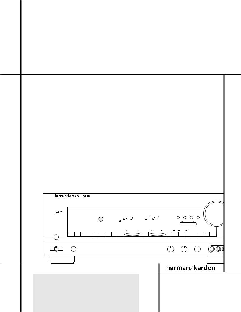
AVR 100 Audio/Video Receiver
OWNER’S MANUAL
|
|
|
|
|
|
|
|
|
|
|
|
|
|
|
|
|
|
|
|
|
|
|
Volume |
|
|
|
|
|
|
|
|
|
|
|
|
|
|
|
|
|
|
Speaker Channel Dig. Select |
Delay |
|
|||
|
|
|
|
|
|
|
|
|
|
|
|
|
|
|
|
|
|
|
|||||
|
|
|
|
|
|
|
|
|
|
|
|
|
|
|
|
|
|
|
|||||
|
|
|
|
|
|
|
|
|
|
|
|
|
|
|
|
|
|
|
|||||
|
|
|
|
|
|
|
|
|
|
|
COAX |
|
|
|
|
|
|
|
|
|
|
|
|
|
|
|
|
|
|
|
|
|
|
|
|
DIGITAL |
|
|
|
|
|
|
|
Set |
|
|
|
|
|
|
|
|
|
|
|
|
|
|
|
|
|
|
|
|
|
|
|
|
|
||
|
|
|
|
|
|
|
|
|
|
|
|
|
|
|
|
|
|
|
|
|
|
|
|
|
|
|
|
|
|
|
|
|
|
|
|
|
|
|
|
|
|
|
|
|
|
|
|
|
|
|
SLEEP |
TAPE |
CD |
DVD |
VID 1 |
VID 2 |
VID 3 |
|
6 CH. |
AM/FM |
TUNING |
PRESET SCAN |
PRESET |
FM MODE |
DIGITAL |
PRO LOGIC 3-STEREO HALL |
THEATER |
TEST TONE SURR. OFF |
|||
Power |
Phones |
|
|
|
|
|
|
|
|
|
|
|
|
|
Bass |
|
Treble |
Balance |
VIDEO 3 |
||||
Min |
Max |
Min |
Max |
L |
R |
Video |
L |
Audio |
|
|
|
|
|
|
|
® |
|
Power for the digital revolution.™
Version 7
October 5, 1999

AVR 100 Audio/Video Receiver
3Introduction
4Safety Information
4Unpacking
5Front-Panel Controls
7Front-Panel Information Display
8Rear-Panel Connections
10 Remote Control Functions
13 Installation and Connections
15 System Configuration
19 Operation
19Basic Operation
19Source Selection
20Surround-Mode Selection
21Surround-Mode Chart
22Tuner Operation
23Tape Recording
23Output-Level Trim Adjustment
236-Channel Direct Input
23Memory Backup
24Programming the Remote
24Direct Code Entry
24Auto-Search Method
24Code Readout
25Programmed Device Functions
25Resetting the Remote Memory
25Reassigning the DVD Button
27Function List
28 |
Setup Code Tables: TV |
30 |
Setup Code Tables: VCR |
32Setup Code Tables: DVD
33Setup Code Tables: LD
34Troubleshooting Guide
34Processor Reset
35Technical Specifications
Typographical Conventions
In order to help you use this manual with the remote control, front-panel controls and rear-panel connections, certain conventions have been used.
EXAMPLE – (bold type) indicates a specific remote control or front-panel button, or rear-panel connection jack
EXAMPLE – (OCR type) indicates a message that is visible on the front-panel information display
EXAMPLE – (outlined type) indicates a lit indicator in the front-panel information display
1– (number in a square) indicates a specific front-panel control
a– (number in an oval) indicates a button or indicator on the remote
¡ – (number in a circle) indicates a rear-panel connection
A– (letter in a square) indicates an indicator in the front-panel display
2 TABLE OF CONTENTS

Introduction
Thank you for choosing Harman Kardon!
With the purchase of a Harman Kardon
AVR 100 you are about to begin many years of listening enjoyment. The AVR 100 has been custom designed to provide all the excitement and detail of movie sound tracks and every nuance of musical selections. With onboard Dolby* Digital, the AVR 100 delivers six discrete channels of audio that take advantage of the digital sound tracks from the latest DVD and LD movies and Digital Television (DTV/HDTV) broadcasts.
While complex digital systems are hard
at work within the AVR 100 to make all of this happen, hookup and operation are simple. Color-keyed connections and a programmable remote control make the AVR 100 easy to use. To obtain the maximum enjoyment from your new receiver, we urge you to take a few minutes to read through this manual. This will ensure that connections to speakers, source playback units and other external devices are made properly. In addition, a few minutes spent learning the functions of the various controls will enable you to take advantage of all the power the AVR 100 is able to deliver.
If you have any questions about this product, its installation or its operation, please contact your dealer or custom installer. They are your best local source of information.
Description and Features
The AVR 100 is a full-featured A/V receiver, incorporating a wide variety of listening options. In addition to Dolby Digital decoding, Dolby Pro Logic* and Dolby 3 Stereo are available for compatibility with the tens of thousands of movies and television programs encoded with analog surround information. In addition, specially programmed Theater and Hall modes are available to enhance the enjoyment of conventional two-channel stereo recordings.
A total of four audio/video inputs, as well as three additional audio-only inputs, are selected through a learning remote control and an easy- to-read front-panel display.
The AVR 100’s powerful amplifier uses traditional Harman Kardon high-current design technologies to meet the wide dynamic range of any program selection.
Harman Kardon invented the high-fidelity receiver more than forty-five years ago. With state-of-the-art circuitry and time-honored circuit designs, the AVR 100 is one of the finest receivers ever offered by Harman Kardon.
■Onboard Dolby Digital Decoding
■Coax and Optical Digital Inputs
■Programmable Remote Control
■Composite Video Switching
■6-Channel Direct Input for use with external surround decoders or DVD-Audio
CAUTION
RISK OF ELECTRIC SHOCK
DO NOT OPEN
CAUTION: To prevent electric shock, do not remove the grounding plug on the power cord, or use any plug or extension cord that does not have a grounding plug provided.
Make certain that the
AC outlet is properly grounded. Do not use an adapter plug with this product.
The lightning flash with arrowhead symbol, within an equilateral triangle, is intended to alert the user to the presence of uninsulated “dangerous voltage” within the product’s
enclosure that may be of sufficient magnitude to constitute a risk of electric shock to persons.
The exclamation point within an equilateral triangle is intended to alert the user to the presence of important operating and maintenance (servicing) instructions in the
literature accompanying the appliance.
3 INTRODUCTION

Safety Information
Important Safety Information
Verify Line Voltage Before Use
Your AVR 100 has been designed for use with 120-volt AC current. Connection to a line voltage other than that for which it is intended can create a safety and fire hazard and may damage the unit.
If you have any questions about the voltage requirements for your specific model, or about the line voltage in your area, contact your selling dealer before plugging the unit into a wall outlet.
Do Not Use Extension Cords
To avoid safety hazards, use only the power cord attached to your unit. We do not recommend that extension cords be used with this product. As with all electrical devices, do not run power cords under rugs or carpets or place heavy objects on them. Damaged power cords should be replaced immediately with cords meeting factory specifications.
Handle the AC Power Cord Gently
When disconnecting the power cord from an AC outlet, always pull the plug, never pull the cord. If you do not intend to use the unit for any considerable length of time, disconnect the plug from the AC outlet.
Do Not Open the Cabinet
There are no user-serviceable components inside this product. Opening the cabinet may present a shock hazard, and any modification to the product will void your guarantee. If water or any metal object such as a paper clip, wire or a staple accidentally falls inside the unit, disconnect it from the AC power source immediately, and consult an authorized service station.
CATV or Antenna Grounding
If an outside antenna or cable system is connected to this product, be certain that it is grounded so as to provide some protection against voltage surges and static charges. Section 810 of the National Electrical Code, ANSI/NFPA No. 70-1984, provides information with respect to proper grounding of the mast and supporting structure, grounding of the leadin wire to an antenna discharge unit, size of grounding conductors, location of antenna discharge unit, connection to grounding electrodes and requirements of the grounding electrode.
NOTE TO CATV SYSTEM INSTALLER: This reminder is provided to call the CATV (Cable TV) system installer’s attention to article 820-
40 of the NEC that provides guidelines for proper grounding and, in particular, specifies that the cable ground shall be connected to the grounding system of the building, as close to the point of cable entry as possible.
Installation Location
■To assure proper operation and to avoid the potential for safety hazards, place the unit on a firm and level surface. When placing the unit on a shelf, be certain that the shelf and any mounting hardware can support the weight of the product.
■Make certain that proper space is provided both above and below the unit for ventilation. If this product will be installed in a cabinet or other enclosed area, make certain that there is sufficient air movement within the cabinet. Under some circumstances a fan may be required.
■Do not place the unit directly on a carpeted surface.
■Avoid installation in extremely hot or cold locations, or an area that is exposed to direct sunlight or heating equipment.
■Avoid moist or humid locations.
■Do not obstruct the ventilation slots on the top of the unit, or place objects directly over them.
Cleaning
When the unit gets dirty, wipe it with a clean, soft, dry cloth. If necessary, wipe it with a soft cloth dampened with mild soapy water, then a fresh cloth with clean water. Wipe dry immediately with a dry cloth. NEVER use benzene, aerosol cleaners, thinner, alcohol or any other volatile cleaning agent. Do not use abrasive cleaners, as they may damage the finish of metal parts. Avoid spraying insecticide near the unit.
Moving the Unit
Before moving the unit, be certain to disconnect any interconnection cords with other components, and make certain that you disconnect the unit from the AC outlet.
Important Information for the User
This equipment has been tested and found to comply with the limits for a Class-B digital device, pursuant to Part 15 of the FCC Rules. The limits are designed to provide reasonable protection against harmful interference in a residential installation. This equipment generates, uses and can radiate radio-frequency energy and, if not installed and used in accordance with the instructions, may cause harmful inter-
ference to radio communication. However, there is no guarantee that harmful interference will not occur in a particular installation. If this equipment does cause harmful interference to radio or television reception, which can be determined by turning the equipment off and on, the user is encouraged to try to correct the interference by one or more of the following measures:
■Reorient or relocate the receiving antenna.
■Increase the separation between the equipment and receiver.
■Connect the equipment into an outlet on a circuit different from that to which the receiver is connected.
■Consult the dealer or an experienced radio/TV technician for help.
This device complies with Part 15 of the FCC Rules. Operation is subject to the following two conditions: (1) this device may not cause harmful interference, and (2) this device must accept interference received, including interference that may cause undesired operation.
NOTE: Changes or modifications may cause this unit to fail to comply with Part 15 of the FCC Rules and may void the user’s authority to operate the equipment.
Unpacking
The carton and shipping materials used to protect your new receiver during shipment were specially designed to cushion it from shock and vibration. We suggest that you save the carton and packing materials for use in shipping if you move, or should the unit ever need repair.
To minimize the size of the carton in storage, you may wish to flatten it. This is done by carefully slitting the tape seams on the bottom and collapsing the carton. Other cardboard inserts may be stored in the same manner. Packing materials that cannot be collapsed should be saved along with the carton in a plastic bag.
If you do not wish to save the packaging materials, please note that the carton and other sections of the shipping protection are recyclable.
Please respect the environment and discard those materials at a local recycling center.
4 SAFETY INFORMATION

Front-Panel Controls
36 |
35 |
|
˘ ˆ |
 ¸¯˜
¸¯˜
Volume
|
|
|
|
|
|
|
|
|
|
|
|
|
|
|
|
Speaker Channel Dig. Select |
Delay |
|
|||
|
|
|
|
|
|
|
|
|
|
|
|
|
|
|
|
|
|||||
|
|
|
|
|
|
|
|
|
COAX |
|
|
|
|
|
|
|
|
|
|
|
|
|
|
|
|
|
|
|
|
|
|
DIGITAL |
|
|
|
|
|
|
|
Set |
|
|
|
|
|
|
|
|
|
|
|
|
|
|
|
|
|
|
|
|
|
|
|
||
|
|
|
|
|
|
|
|
|
|
|
|
|
|
|
|
|
|
|
|
|
|
|
|
|
|
|
|
|
|
|
|
|
|
|
|
|
|
|
|
|
|
|
|
|
SLEEP |
TAPE |
CD |
DVD |
VID 1 |
VID 2 |
VID 3 |
|
6 CH. |
AM/FM |
TUNING |
PRESET SCAN |
PRESET |
FM MODE |
DIGITAL |
PRO LOGIC 3-STEREO HALL |
THEATER |
TEST TONE SURR. OFF |
|||
|
|
|
|
|
|
|
Mute |
1 |
|
|
|
|
|
|
|
Power |
Phones |
Bass |
Treble |
|
Balance |
|
VIDEO 3 |
2 |
|
|
|
|
|
|
|
|
|
Min Max |
Min Max |
L |
R |
Video |
L Audio R |
3 |
4 |
5 |
6 |
|
7 |
|
8 |
|
9 )!@ # $% ^ & * ( ÓÔ ÒÚÛ Ù ı |
||||||
1 Main Power Switch
2 System Power Control
3 Power Indicator
4 Headphone Jack
5 Bass Control
6 Treble Control
7 Balance Control
8 Video 3 Inputs
9 Sleep Button
)Tape Input Selector
! CD Input Selector
@ DVD Input Selector
1 Main Power Switch: Press this button to apply power to the AVR 100. When the switch is pressed in, the unit is placed in a Standby mode, as indicated by the amber LED 3surrounding the System Power Control 2. This button MUST be pressed in to operate the unit. To turn the unit off and prevent the use of the remote control, this switch should be pressed until it pops out from the front panel so that the word “OFF” may be read at the top of the switch.
NOTE: In normal operation this switch is left in the “ON” position.
2 System Power Control: When the Main Power Switch 1is “ON,” press this button
# Video Input Selector
$ 6-Channel Selector
% AM/FM Button
^ Tuning Selector
& Preset Scan
* Preset Stations Selector
( Tuner Mode
Ó Dolby Digital Selector
Ô Dolby Pro Logic Selector
Dolby 3 Stereo Selector
Ò Hall Mode Selector
Ú Theater Mode Selector
to turn on the AVR 100; press it again to turn the unit off. Note that the Power Indicator surrounding the switch 3will turn green when the unit is on.
3 Power Indicator: This LED will illuminate in amber when the unit is in the Standby mode to signal that the unit is ready to be turned on. When the unit is in operation, the indicator will turn green.
4Headphone Jack: This jack may be used to listen to the AVR 100’s output through a pair of headphones. Be certain that the headphones have a standard 1/4" stereo phone plug. Note that the main room speakers will automatically be turned off when the headphone jack is in use.
Û Test Tone Button
Ù Surround Off
ı Mute
ˆ Volume Control
˜ Delay
¯ Digital Input Selector
˘ Set Button
¸ Channel Trim Button
33Speaker Select Button
34Selector Buttons
35Information Display
36Remote Sensor
5Bass Control: Turn this control to modify the low-frequency output of the left/right channels by as much as ±10dB. Set this control to a suitable position for your taste or room acoustics.
6Treble Control: Turn this control to modify the high-frequency output of the left/right channels by as much as ±10dB. Set this control to a suitable position for your taste or room acoustics.
7 Balance Control: Turn this control to change the relative volume for the front left/right channels.
NOTE: For proper operation of the surround modes this control should be at the midpoint or “12 o’clock” position.
5 FRONT-PANEL CONTROLS
Front-Panel Controls
8Video 3 Inputs: These audio/video inputs may be used for temporary connection of video games, camcorders, digital still cameras or portable audio products. To select a source connected to these jacks, press the Vid 3 Input Selector #.
9 Sleep Button: Press this button to place the AVR in the Sleep mode. Once the button is pressed, Information Display 35will show the time remaining before the unit will automatically go into the Standby mode. To decrease the remaining time before the unit goes into Standby, press the button again, and each press will decrease the time in the following order:
|
|
|
90 |
|
|
|
80 |
|
|
|
70 |
|
|
|
60 |
|
|
50 |
|
|
|
|
|
min |
|
|
min |
|
|
min |
|
|
min |
|
|
|
min |
|
|||
|
|
|
|
|
|
|
|
|
|
|
|
|
|
|
|
|
|
|
|
|
|
|
40 |
|
|
30 |
|
|
20 |
|
|
10 |
|
|
|
OFF |
|||||
|
|
|
min |
|
|
min |
|
|
min |
|
|
min |
|
|
|
|||||
|
|
|
|
|
|
|
|
|
|
|
|
|
|
|||||||
To cancel the Sleep timer setting, press and hold the button for two seconds and then release it.
)Tape Selector: Press this button to select the device connected to the Tape In jacks • as the listening source.
! CD: Press this button to select the device connected to the CD Input jacks ¶ as the listening source.
@ DVD Input Selector: Press this button to select the device connected to the DVD Input jacks § as the listening and viewing source.
#Video Input Selectors: Press one of these buttons to select a source connected to the rear panel Video inputs fl ‡, or the front panel Video 3 input 8.
$ 6-Channel Direct Selector: Press this button to select the output of an optional, external 6-channel decoder connected to the 6-Ch Direct inputs · as the listening source.
%AM/FM: Press this button to select the tuner as the AVR 100’s input source. When it is first pressed the last station tuned will be heard. Press it again to change between AM and FM bands.
^Tuning Button: Press the left side of the button to tune lower frequency stations and the right side of the button to tune higher frequency stations. When a station with a strong signal is reached, the TUNED indicator Mwill illuminate in the Information Display 35.
To tune manually, tap the button lightly and note that the tuner will step up one frequency per button press. When the button is held for a few seconds you will note that the unit will quickly search the frequency band. Release it
once the fast tuning starts and the tuner will automatically scan for the next station with an acceptable signal and then stop.
& Preset Scan: Press this button to automatically scan through the stations that have been programmed in the AVR 100’s memory. The tuner will play five seconds of each station before moving to the next preset station. To stop the scan when the desired station is heard, press the button again. (See page 22 for more information on the tuner memory system.)
* Preset Stations Selector: Press this button to select stations that have been entered into the preset memory. (See page 22 for more information on tuner programming.)
(Tuner Mode: Press this button to select the stereo or mono mode for FM tuning. In the STEREO mode a Stereo indicator Kwill illuminate in the information display, and stereo reception will be provided when stations are transmitting stereo signals. In the MONO mode the left and right signals from stereo broadcasts will be mixed together. Select MONO for better reception of weak signals.
Ó Dolby Digital Selector: Press this button to select the Dolby Digital surround mode when listening to a program that carries Dolby Digital information. (See pages 20–22 for more information on surround modes and digital audio.)
Ô Dolby Pro Logic Selector: Press this button to select the Dolby Pro Logic surround mode when listening to an analog program that is encoded with surround-sound information. (See page 20–22 for more information on surround modes.)
Dolby 3 Stereo Selector: Press this button to select the Dolby 3 Stereo listening mode. This mode is used primarily when a center channel speaker, but no surround speakers, is installed. (See pages 21 for more information on surround modes.)
Ò Hall Mode Selector: Press this button to activate the Hall mode as an alternative surround mode when stereo sources are in use. This mode provides the reverberant atmosphere of a medium-sized concert hall.
ÚTheater Mode Selector: Press this button to activate the Theater mode as an alternate surround mode when stereo sources are in use.
ÛTest Tone Button: Press this button to begin the process of setting the AVR 100’s output levels. When this button is pressed, a test tone will replace the listening source, and circulate among the various output channels at a three-second interval. The Information
Display 35 will show the location of the channel where the test tone noise should be heard. (See page 17 for complete information on setting the output levels.)
Ù Surround Off: Press this button to turn off all surround processing and to listen to a program in traditional stereo from the left-front and right-front speakers only.
ı Mute: Press this button to momentarily silence the speaker and headphone outputs of the AVR 100.
ˆVolume Control: Turn the knob clockwise to increase volume, counterclockwise to decrease the volume. If the AVR is muted, adjusting volume control will automatically release the unit from the silenced condition.
˜ Delay: Press this button to begin the sequence of steps required to enter delay time settings. (See pages 17–18 for more information on delay times.)
¯ Digital Input Selector: When playing a source that has a digital output, press this button to select between the Optical fi and Coaxial › Digital inputs. (See pages 20–22 for more information on digital audio.)
˘Set Button: When making choices during the setup and configuration process, press this button to enter the desired setting, as shown in the Information Display 35,, into the AVR 100’s memory.
¸ Channel Trim Button: Press this button to trim the output level settings using an input source as the program material. (See page 23 for complete information on trimming the output levels.)
33Speaker Select Button: Press this button to begin the process of selecting the speaker positions that are used in your listening room. (See pages 16–18 for more information on setup and configuration.)
34Selector Buttons: When you are establishing the AVR 100’s configuration settings, use these buttons to select between the choices available, as shown in the Information Display 35,.
35Information Display: This display delivers messages and status indications to help you operate the receiver. (See page 7 for a complete explanation of the Information Display.)
36Remote Sensor Window: The sensor behind this window receives infrared signals from the remote control. Aim the remote at this area and do not block or cover it unless an external remote sensor is installed.
6 FRONT PANEL CONTROLS
Front-Panel Information Display
Q P O N M L K J


 I
I
H
|
|
|
|
|
|
|
|
|
|
|
|
|
|
|
A |
|
B |
|
C |
|
|
|
|
|
|||
|
|
|
|
|
|
|
|
||||||
|
|
|
D |
E |
F |
G |
|||||||
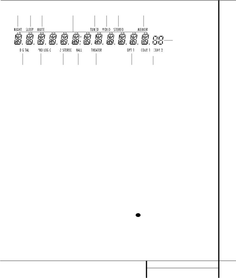
A Dolby Digital Indicator |
|
|
|
G Coax Source Indicators |
|
M Tuned Indicator |
|||||||
B Dolby Pro Logic Indicator |
|
|
|
H Preset Number |
|
N Main Information Display |
|||||||
CDolby 3 Stereo Indicator |
|
|
|
I Preset Indicator |
|
O Mute Indicator |
|||||||
D Hall Mode Indicator |
|
|
|
J Memory Indicator |
|
P Sleep Mode Indicator |
|||||||
E Theater Mode Indicator |
|
|
|
K Stereo Indicator |
|
Q Night Mode Indicator |
|||||||
F Optical Source Indicator |
|
|
|
L Mono Indicator |
|
|
|
||||||
A Dolby Digital Indicator: This indicator illuminates when a Dolby Digital source is being played.
B Dolby Pro Logic Indicator: This indicator illuminates when the AVR is in the Dolby Pro Logic mode.
C Dolby 3 Stereo Indicator: This indicator illuminates when the AVR is in the Dolby 3 Stereo mode.
D Hall Mode Indicator: This indicator illuminates when the Hall mode is in use.
ETheater Mode Indicator: This indicator illuminates when the Theater mode is in use.
F Optical Source: This indicator illuminates when a digital source is in use via a connection to the Optical Digital input fi.
G Coax Source Indicator: This indicator illuminates when a digital source is in use via a connection to either of the Coaxial Digital inputs ›.
HPreset Number: This two-digit display indicates the station preset number that is currently in use or that is being entered.
IPreset Indicator: This indicator illuminates when a station previously entered into the preset memory is tuned. The number that appears below the indicator is the preset station’s memory position.
J Memory: This indicator flashes when entering presets and other information into the tuner’s memory.
K Stereo Indicator: This indicator illuminates when an FM station is being tuned in stereo.
L Mono Indicator: This indicator illuminates when the tuner has been placed in the monaural mode by pressing the Tuner Mode button f (. Set the tuner for mono listening to reduce noise and improve the quality of distant stereo signals.
M Tuned Indicator: This indicator illuminates when a station is being received with sufficient signal strength to provide acceptable listening quality.
N Main Information Display: This display shows messages relating to the status, input source, surround mode, tuner, volume level or other aspects of the AVR’s operation.
OMute: This indicator illuminates to remind you that the AVR 100’s output has been silenced by pressing the Mute button ı 32 . Press the Mute button again to return to the previously selected output level.
P Sleep Indicator: This indicator is illuminated when the Sleep function is in use. The number that appears above the indicator is the number of minutes remaining before the AVR 100 will return to the Standby mode.
Q Night Mode Indicator: This indicator lights when the AVR 100 is in the Night mode, which preserves the dynamic range of digital program material at low volume levels.
7 FRONT-PANEL INFORMATION DISPLAY
Rear-Panel Connections
|
|
· ° |
|
‡ fl |
fi › |
|
|
|
|
|
|||
|
6 |
R |
L |
R-AUDIO-L |
|
VIDEO |
|
|
|
|
|
|
|
|
|
|
|
|
|
|
|
|
|
|
|
|
|
|
C |
|
|
|
REC. |
|
|
|
|
|
|
|
|
|
|
|
|
OUT |
|
|
|
|
|
|
|
|
|
|
H. |
|
|
|
|
|
|
|
|
|
|
|
|
|
FRONT |
|
|
|
|
|
|
|
|
|
|
|
|
ANTENNA |
D |
|
|
|
VIDEO 1 |
|
DIGITAL INPUT |
|
|
|
|
|
|
|
|
|
|
|
|
|
|
|
|
|
|
|
|
|
I |
|
|
|
PLAY |
|
OPTICAL |
|
|
|
|
|
|
|
R |
|
|
|
|
|
|
|
|
|
|
||
|
|
|
|
IN |
|
|
|
|
|
|
|
||
|
E |
SURR. |
|
|
|
|
|
|
|
|
|
|
|
|
|
|
|
|
|
|
|
|
|
|
|
||
|
C |
|
|
|
|
|
|
|
|
|
|
|
|
|
T |
|
|
|
|
|
|
|
|
|
|
|
|
¡ AM |
I |
|
|
|
VIDEO 2 |
|
|
|
|
|
|
|
|
SUB |
|
|
IN |
|
|
|
|
|
|
|
|
||
N |
WOOFER |
|
CENTER |
|
|
|
|
|
|
|
|
|
|
|
|
|
|
|
|
|
|
|
|
|
|
||
LOOP |
|
|
|
|
|
|
|
|
|
|
|
|
|
|
|
|
|
|
DVD IN |
|
|
|
|
|
|
|
|
|
|
|
|
|
|
|
COAX. 1 |
|
|
|
|
|
|
™ |
|
|
|
|
CD IN |
VIDEO |
|
|
|
S P E A K E R S 8 O h m s |
|
|
|
|
|
|
|
MON. |
|
|
|
|
AC 120V 60Hz |
||||
FM |
|
|
|
|
|
OUT |
COAX. 2 |
|
|
|
|
|
|
75Ω |
|
|
|
|
|
|
|
|
|
|
|
||
|
|
|
|
|
|
|
|
|
|
|
|
|
|
|
|
|
|
|
|
|
|
|
|
|
|
|
SWITCHED 100W 1A MAX |
|
|
SUB |
|
|
REC. |
|
|
|
|
|
|
|
|
|
|
WOOFER |
|
|
OUT |
|
|
|
|
|
|
|
|
£ |
|
OUT |
|
|
TAPE |
|
|
|
|
|
|
|
|
|
|
|
|
|
|
|
|
|
|
|
|
||
|
|
|
|
PLAY |
|
|
|
|
|
|
|
450W |
|
IN |
|
|
|
|
|
|
|
|
|
|
|
||
|
|
|
|
IN |
|
|
|
|
|
|
|
|
|
¢ |
|
|
|
|
|
|
|
|
|
|
|
|
|
OUT |
|
|
|
|
|
|
|
|
|
|
|
|
|
REMOTE CONTROL |
|
|
|
|
|
|
|
SURR. |
FRONT |
CENTER |
FRONT |
SURR. |
SWITCHED 100W 1A MAX |
|
|
|
|
|
|
|
RIGHT |
RIGHT |
|
LEFT |
LEFT |
||
|
|
|
|
|
|
|
|
|
|
||||
|
|
§ ¶ • ª ‚ |
|
|
|
⁄ |
|
|
¤ ‹ |
||||
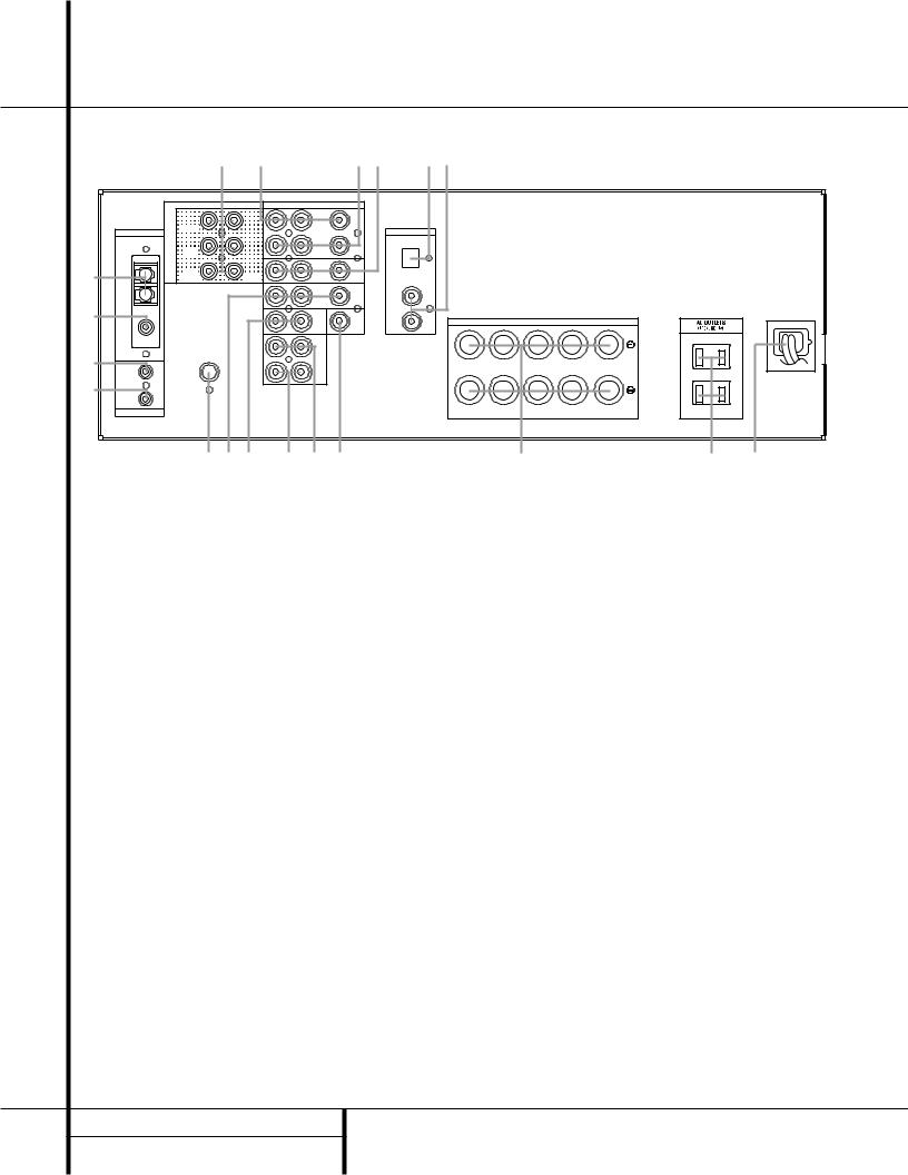
¡ AM Antenna |
ª Tape Outputs |
‡ Video 1 |
Inputs |
™ FM Antenna |
‚ Video Monitor Output |
° Video 1 |
Outputs |
£ Remote IR Input |
⁄ Speaker Output Terminals |
· 6-Channel Direct Inputs |
|
¢ Remote IR Output |
¤ Switched AC Outlet |
|
|
Subwoofer Output |
‹ AC Power Cord |
|
|
§ DVD Inputs |
› Coax Digital Inputs |
|
|
¶ CD Inputs |
fi Optical Digital Input |
|
|
• Tape Inputs |
fl Video 2 Inputs |
|
|
8 REAR-PANEL CONNECTIONS

Rear-Panel Connections
¡ AM Antenna: Connect the AM loop antenna supplied with the receiver to these terminals. If an external AM antenna is used, make connections to the AM and GND terminals in accordance with the instructions supplied with the antenna.
™ FM Antenna: Connect the supplied indoor or an optional external FM antenna to this terminal.
£ Remote IR Input: If the AVR 100’s frontpanel IR sensor is blocked due to cabinet doors or other obstructions, an external IR sensor may be used. Connect the output of the sensor to this jack.
¢ Remote IR Output: This connection permits the IR sensor in the receiver to serve other remote-controlled devices. Connect this jack to the “IR IN” jack on compatible equipment.
Subwoofer Output: Connect this jack to the line-level input of a powered subwoofer. If an external subwoofer amplifier is used, connect this jack to the subwoofer amplifier input.
§ DVD Inputs: Connect the analog audio outputs and composite video output of a DVD or LD player to these jacks.
¶ CD Inputs: Connect these jacks to the output of a compact disc player or CD changer.
• Tape Inputs: Connect these jacks to the PLAY/OUT jacks of an audio recorder.
ª Tape Outputs: Connect these jacks to the RECORD/INPUT jacks of an audio recorder.
‚ Video Monitor Output: Connect this jack to the composite video input of a TV monitor or video projector to view the output of any standard video source selected by the receiver’s video switcher.
⁄ Speaker Terminals: Connect these terminals to the appropriate speakers, following the designations shown.
NOTE: When making connections to the Speaker Terminals always be certain to maintain correct polarity between the speaker’s terminals and those on the AVR by connecting red (+) terminals to red, and black (–) terminals to black. (See page 13 for more information on speaker polarity.)
¤ Switched AC Outlet: This outlet may be used to power any device that you wish to have turn on when the unit is turned on with the
System Power Control switch 2.
NOTE: The power consumption of the device plugged into this outlet ¤ should not exceed 100 watts.
‹ AC Power Cord: Connect the AC plug to a nonswitched AC wall output.
› Coaxial Digital Inputs: Connect the coax digital output from a DVD player, HDTV receiver, LD player or CD player to these jacks. The signal may be either a Dolby Digital signal or a standard PCM digital source.
fi Optical Digital Input: Connect the optical digital output from a DVD player, HDTV receiver, LD player or CD player to this jack. The signal may be either a Dolby Digital signal or a standard PCM digital source.
fl Video 2 Inputs: Connect these jacks to the audio and video outputs of a TV Tuner, Cable TV converter box, satellite receiver or any other audio/video source.
‡ Video 1 Inputs: Connect these jacks to the audio and video PLAY/OUT jacks of a VCR.
° Video 1 Outputs: Connect these jacks to the audio and video RECORD/IN jacks of a VCR.
· 6-Channel Direct Inputs: If an external digital audio decoder is used, connect the outputs of that decoder to these jacks.
9 REAR-PANEL CONNECTIONS

Remote Control Functions
a Device Selectors
b AM/FM Tuner Select
c Main Power-Off Button
d Sleep Button
e Night Mode/Dim Switch
f FM Tuner Mode Button
g Disc-Skip Button
h DVD Function Buttons
i Play/Up Button
j Title/CDP Button
k Stop/Enter Button
l Tune Down/Rewind Button
m Pause/Down Button
n Preset Down/Channel-Down Button
o Numeric Keys
pSpeaker Select Button
q Channel-Select Button
r ‹/› Select Buttons
s Test Tone Button
t Set Button
u Digital Input Selector
v Clear Button
w Memory Button
x Direct/Random Play Button
y Slow-Play Buttons
z Delay Button
` Preset Up/Channel-Up Button
●28 Tune Up/Fast-Forward Button
●29 Menu/CDR Button
●30 Device Volume Control
●31 Master Volume Control
●32 Mute Button
●33 Surround Mode Selectors
●34 Open/Close Button
●35 Source Power Controls
●36 6-Channel Direct Selector
●37 Program/Command Indicator
NOTE: The function names shown here are each button’s feature when used with the AVR. Most buttons have additional functions when used with other devices. See page 27 for a list of these functions.
a |
|
TV |
VCR |
|
|
|
|
V1 |
V2 |
V3 |
DVD |
||
|
b |
|
INPUT/POWER ON |
|
||
|
AM/FM |
CD |
TAPE |
6 CH |
||
|
|
|||||
|
|
MAIN POWER |
SOURCE POWER |
|||
c d |
OFF |
|
ON |
OFF |
||
DIM/NIGHT |
SLEEP |
|
|
|||
e |
f |
|
|
|
|
|
g |
DISC SKIP |
MODE |
MUTE |
SURR. |
||
|
||||||
|
PS |
|
|
|
||
|
|
|
|
|
||
|
|
SUBTITLE |
ON/OFF |
|
|
|
|
h |
ANGLE |
AUDIO |
VOLUME |
MASTER VOL |
|
|
|
|||||
|
|
Sin |
Du |
|
|
|
i |
|
|
|
|
|
|
|
j |
TITLE |
|
|
MENU |
|
|
CDP |
|
|
CDR |
||
k
m
|
TUNING |
l |
R |
E |
|
|
W |
nCH
UP
STOP ENTER
DOWN
 /
/
TUNING
F
F
CH
|
|
DOWN |
|
PRESET TUNING |
|
UP |
o |
|
1 |
2 |
3 |
4 |
5 |
|
|
|
|
|
|
|
|
p |
6 |
7 |
8 |
9 |
0 |
|
SPK |
CH |
DELAY |
SLOW |
||
|
|
|||||
q |
r |
|
|
CLEAR |
RANDOM |
|
|
|
SET |
|
|
DIR |
|
s |
|
TEST TONE |
|
DIGITAL INPUT |
|
MEMORY |
|
|
|
|
|
PROG. |
|
t
37
36
35
34
33
32
31
30
29
28
`
z
y
x
w v u
10 REMOTE CONTROL FUNCTIONS
 Loading...