


W10CBS
Graco W10CBS, W15BBS, W15AAS, W15BAS, W15FAS Assembly
...
Instructions - Parts
®
Merkur
Pump
312794F
Assembly
For high-performance finishing and coating applications in hazardous or non-hazardous
locations. For professional use only.
Important Safety Instructions
Read all warnings and instructions in this manual.
Save these instructions.
See page 4 for model information, including maximum working pressure.
EN
TI12811a
ll 2 G

Contents
Pump Part Number Matrix . . . . . . . . . . . . . . . . . . . 3
Pump Models . . . . . . . . . . . . . . . . . . . . . . . . . . . . . . 4
Warnings . . . . . . . . . . . . . . . . . . . . . . . . . . . . . . . . . 5
Related Manuals . . . . . . . . . . . . . . . . . . . . . . . . . . . 6
Component Identification . . . . . . . . . . . . . . . . . . . . 7
Installation . . . . . . . . . . . . . . . . . . . . . . . . . . . . . . . . 8
General Information . . . . . . . . . . . . . . . . . . . . . . 8
Prepare the Operator . . . . . . . . . . . . . . . . . . . . . 8
Prepare the Site . . . . . . . . . . . . . . . . . . . . . . . . . 8
Grounding . . . . . . . . . . . . . . . . . . . . . . . . . . . . . . 8
Mount the Pump . . . . . . . . . . . . . . . . . . . . . . . . . 9
Air and Fluid Hoses . . . . . . . . . . . . . . . . . . . . . . . 9
Accessories . . . . . . . . . . . . . . . . . . . . . . . . . . . . . 9
Typical Installation . . . . . . . . . . . . . . . . . . . . . . . 10
Operation . . . . . . . . . . . . . . . . . . . . . . . . . . . . . . . . 11
Pressure Relief Procedure . . . . . . . . . . . . . . . . 11
Flush Before Using Equipment . . . . . . . . . . . . . 11
Trigger Lock . . . . . . . . . . . . . . . . . . . . . . . . . . . . 11
Wet Cup . . . . . . . . . . . . . . . . . . . . . . . . . . . . . . 11
Prime and Adjust the Pump . . . . . . . . . . . . . . . 12
Shutdown and Care of the Pump . . . . . . . . . . . 12
Maintenance . . . . . . . . . . . . . . . . . . . . . . . . . . . . . . 13
Preventive Maintenance Schedule . . . . . . . . . . 13
Tighten Threaded Connections . . . . . . . . . . . . . 13
Flush the Pump . . . . . . . . . . . . . . . . . . . . . . . . . 13
Wet Cup . . . . . . . . . . . . . . . . . . . . . . . . . . . . . . . 13
Troubleshooting . . . . . . . . . . . . . . . . . . . . . . . . . . . 14
Repair . . . . . . . . . . . . . . . . . . . . . . . . . . . . . . . . . . . 15
General Information . . . . . . . . . . . . . . . . . . . . . . 15
Disconnect the Displacement Pump . . . . . . . . . 15
Reconnect the Displacement Pump . . . . . . . . . 16
Disconnect the Air Motor . . . . . . . . . . . . . . . . . . 17
Reconnect the Air Motor . . . . . . . . . . . . . . . . . . 17
Pump Parts . . . . . . . . . . . . . . . . . . . . . . . . . . . . . . . 18
Parts That Vary by Model . . . . . . . . . . . . . . . . . 20
Repair Kits . . . . . . . . . . . . . . . . . . . . . . . . . . . . . . . 21
Performance Charts . . . . . . . . . . . . . . . . . . . . . . . . 22
Pump Dimensions . . . . . . . . . . . . . . . . . . . . . . . . . 29
Wall Bracket Mounting Dimensions . . . . . . . . . . . 30
Technical Data . . . . . . . . . . . . . . . . . . . . . . . . . . . . 31
Graco Standard Warranty . . . . . . . . . . . . . . . . . . . 32
Graco Information . . . . . . . . . . . . . . . . . . . . . . . . . 32
2 312794F
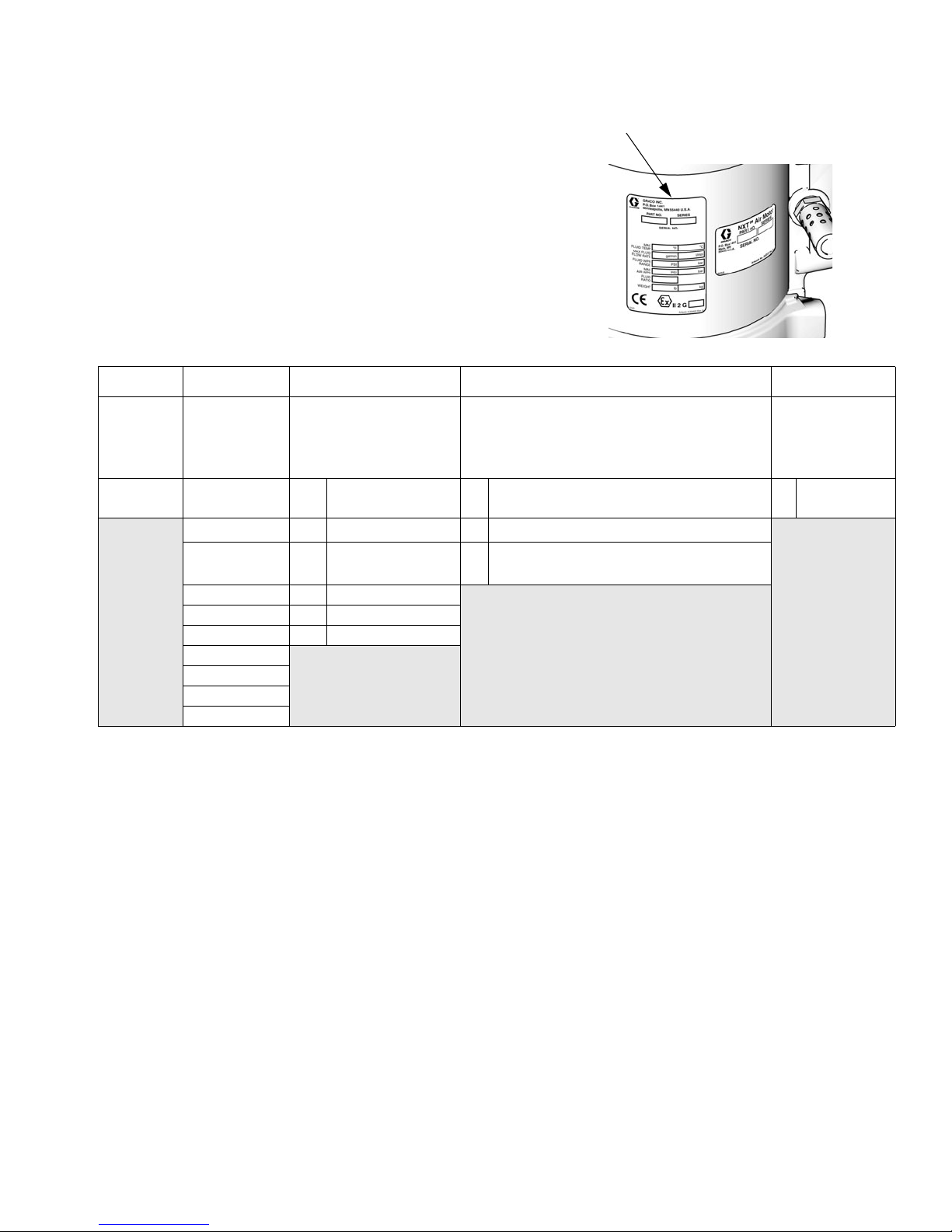
Pump Part Number Matrix
Pump Part Number Matrix
Check your pump’s identification plate (ID) for the 6-digit part number.
Use the following matrix to define the construction of your pump, based
on the six digits. For example, Part No. W 1 5 A A S represents a wet cup
pump (W), 15 to 1 ratio (15), 25 cc lower (A), 3 UHMWPE/2 PTFE packings with chromex rod coating, no data monitoring, low noise exhaust
(A), and stainless steel construction (S).
ID
W15 A A S
Second and
Third Digits
First Digit
(Wet cup)
W10A25 cc A 3:2/Chromex/No Monitoring/Low Noise S Stainless
(pressure
ratio - XX:1)
15 B 50 cc B
18 C 75 cc E
23 D 100 cc
24 E 125 cc
28 F 150 cc
30
36
45
48
Fourth Digit
(Displacement pump
volume per cycle*)
(Packings - X UHMWPE:X PTFE/
Data Monitoring/Exhaust)
3:2/Chromex/DataTrak
3:2/Chromex/DataTrak
Only/Low Noise
Fifth Digit
Piston Rod Coating/
™
/Low Noise
™
Cycle Count
Sixth Digit
(lower
material)
steel
ti12922a
* Cycle refers to combination of one upstroke and one downstroke.
312794F 3

Pump Models
Pump Models
Maximum Fluid
Air
Model, Series
W10CAS, Series A M04LN0
W10CBS, Series A M04LT0
W15AAS, Series A M02LN0 LW025A 1500 (10.3, 103) 0.4 (1.5) 1/2 in. npt 3/8 in. npt 1/4 npt(f)
W15BAS, Series A M04LN0
W15BBS, Series A M04LT0
W15FAS, Series A M12LN0
W15FBS, Series A M12LT0
W18EAS Series A M12LN0
W18EBS, Series A M12LT0
W23DAS, Series A M12LN0
W23DBS, Series A M12LT0
W24FAS, Series A M18LN0
W24FBS, Series A M18LT0
W28EAS, Series A M18LN0
W28EBS, Series A M18LT0
W30AAS, Series A M04LN0
W30ABS, Series A M04LT0
W30CAS, Series A M12LN0
257463 †, Series A M12LN0
W36DAS, Series A M18LN0
W36DBS, Series A M18LT0
W45BAS, Series A M12LN0
W45BBS, Series A M12LT0
262287 †, Series A M12LN0
262392 †, Series A M12FN0
W48CAS, Series A M18LN0
W48CBS, Series A M18LT0
Motor
Displacement
Pump
LW075A 1000 (6.9, 69) 1.2 (4.5) 3/4 in. npt 3/8 in. npt 1/4 npt(f)
LW050A 1500 (10.3, 103) 0.8 (3.0) 3/4 in. npt 3/8 in. npt 1/4 npt(f)
LW150A 1500 (10.3, 103) 2.4 (9.0) 1 in. npt 3/4 in. npt 1/2 npt(f)
LW125A 1800 (12.4, 124) 2.0 (7.5) 1 in. npt 1/2 in. npt 1/2 npt(f)
LW100A 2300 (15.8, 158) 1.6 (6.0) 3/4 in. npt 3/8 in. npt 1/2 npt(f)
LW150A 2400 (16.5, 165) 2.4 (9.0) 1 in. npt 3/4 in. npt 1/2 npt(f)
LW125A 2800 (19.3, 193) 2.0 (7.5) 1 in. npt 1/2 in. npt 1/2 npt(f)
LW025A 3000 (20.7, 207) 0.4 (1.5) 1/2 in. npt 3/8 in. npt 1/4 npt(f)
LW075A 3000 (20.7, 207) 1.2 (4.5) 3/4 in. npt 3/8 in. npt 1/2 npt(f)W30CBS, Series A M12LT0
LW100A 3600 (24.8, 248) 1.6 (6.0) 3/4 in. npt 3/8 in. npt 1/2 npt(f)
LW050A 4500 (31.0, 310) 0.8 (3.0) 3/4 in. npt 3/8 in. npt 1/2 npt(f)
LW075A 4800 (33.1, 331) 1.2 (4.5) 3/4 in. npt 3/8 in. npt 1/2 npt(f)
Working Pressure
psi (MPa, bar)
Flow Rate
at 60 cpm
gpm (lpm)
Fluid
Inlet
Fluid
Outlet Air Inlet
† Flush Kit Pumps do not utilize the part number matrix.
4 312794F

Warnings
Warnings
The following warnings are for the setup, use, grounding, maintenance, and repair of this equipment. The exclamation point symbol alerts you to a general warning and the hazard symbol refers to procedure-specific risk. Refer back
to these warnings. Additional, product-specific warnings may be found throughout the body of this manual where
applicable.
WARNING
FIRE AND EXPLOSION HAZARD
Flammable fumes, such as solvent and paint fumes, in work area can ignite or explode. To help prevent
fire and explosion:
• Use equipment only in well ventilated area.
• Eliminate all ignition sources; such as pilot lights, cigarettes, portable electric lamps, and plastic drop
cloths (potential static arc).
• Keep work area free of debris, including solvent, rags and gasoline.
• Do not plug or unplug power cords, or turn power or light switches on or off when flammable fumes
are present.
• Ground all equipment in the work area. See Grounding instructions.
• Use only grounded hoses.
• Hold gun firmly to side of grounded pail when triggering into pail.
• If there is static sparking or you feel a shock, stop operation immediately. Do not use equipment
until you identify and correct the problem.
• Keep a working fire extinguisher in the work area.
EQUIPMENT MISUSE HAZARD
Misuse can cause death or serious injury.
• Do not operate the unit when fatigued or under the influence of drugs or alcohol.
• Do not exceed the maximum working pressure or temperature rating of the lowest rated system
component. See Technical Data in all equipment manuals.
• Use fluids and solvents that are compatible with equipment wetted parts. See Technical Data in all
equipment manuals. Read fluid and solvent manufacturer’s warnings. For complete information
about your material, request MSDS forms from distributor or retailer.
• Check equipment daily. Repair or replace worn or damaged parts immediately with genuine manufacturer’s replacement parts only.
• Do not alter or modify equipment.
• Use equipment only for its intended purpose. Call your distributor for information.
• Route hoses and cables away from traffic areas, sharp edges, moving parts, and hot surfaces.
• Do not kink or over bend hoses or use hoses to pull equipment.
• Keep children and animals away from work area.
• Comply with all applicable safety regulations.
SKIN INJECTION HAZARD
High-pressure fluid from gun, hose leaks, or ruptured components will pierce skin. This may look like just
a cut, but it is a serious injury that can result in amputation. Get immediate surgical treatment.
• Do not point gun at anyone or at any part of the body.
• Do not put your hand over the spray tip.
• Do not stop or deflect leaks with your hand, body, glove, or rag.
• Do not spray without tip guard and trigger guard installed.
• Engage trigger lock when not spraying.
• Follow Pressure Relief Procedure in this manual, when you stop spraying and before cleaning,
checking, or servicing equipment.
312794F 5

Related Manuals
PRESSURIZED EQUIPMENT HAZARD
Fluid from the gun/dispense valve, leaks, or ruptured components can splash in the eyes or on skin and
cause serious injury.
• Follow Pressure Relief Procedure in this manual, when you stop spraying and before cleaning,
• Tighten all fluid connections before operating the equipment.
• Check hoses, tubes, and couplings daily. Replace worn or damaged parts immediately.
MOVING PARTS HAZARD
Moving parts can pinch or amputate fingers and other body parts.
• Keep clear of moving parts.
• Do not operate equipment with protective guards or covers removed.
• Pressurized equipment can start without warning. Before checking, moving, or servicing equipment,
TOXIC FLUID OR FUMES HAZARD
Toxic fluids or fumes can cause serious injury or death if splashed in the eyes or on skin, inhaled, or
swallowed.
• Read MSDS’s to know the specific hazards of the fluids you are using.
• Store hazardous fluid in approved containers, and dispose of it according to applicable guidelines.
• Always wear impervious gloves when spraying or cleaning equipment.
WARNING
checking, or servicing equipment.
follow the Pressure Relief Procedure in this manual. Disconnect power or air supply.
PERSONAL PROTECTIVE EQUIPMENT
You must wear appropriate protective equipment when operating, servicing, or when in the operating
area of the equipment to help protect you from serious injury, including eye injury, inhalation of toxic
fumes, burns, and hearing loss. This equipment includes but is not limited to:
• Protective eyewear
• Clothing and respirator as recommended by the fluid and solvent manufacturer
•Gloves
• Hearing protection
Related Manuals
Manual Description
312792 Merkur Displacement Pump
312796
312797 Merkur Non-Heated Spray Packages
312798
313255 Merkur Heated Spray Packages
™
NXT
Air Motor
Merkur Electrostatic Spray Packages,
Ambient and Heated
6 312794F
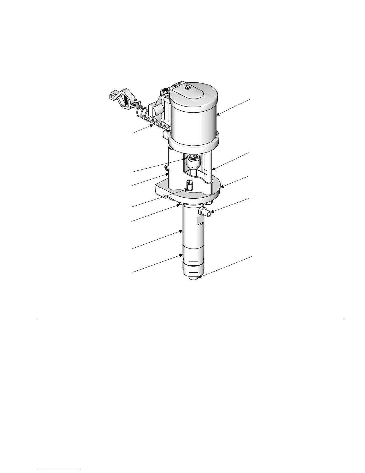
Component Identification
A
Component Identification
N
K
L
H
B
M
G
F
FIG. 1. Component Identification
Key:
A Ground Wire
B TSL Reservoir
C Wet Cup (not visible, under TSL reservoir)
D Fluid Outlet
E Fluid Inlet
F Lower Cylinder
G Upper Cylinder
H Tie Rod Shield
J Displacement Pump Adapter
KTie Rod
L Coupling Nut
MJam Nut
N Air Motor
J
D
E
ti11700a
312794F 7
Installation
Installation
General Information
Reference numbers and letters in parentheses in
the text refer to the callouts in the figures and the
parts drawing.
Always use Genuine Graco Parts and Accessories,
available from your Graco distributor. If you supply
your own accessories, be sure they are adequately
sized and pressure-rated for your system.
Prepare the Operator
All persons who operate the equipment must be trained
in the operation of all system components as well as the
proper handling of all fluids. All operators must thoroughly read all instruction manuals, tags, and labels
before operating the equipment.
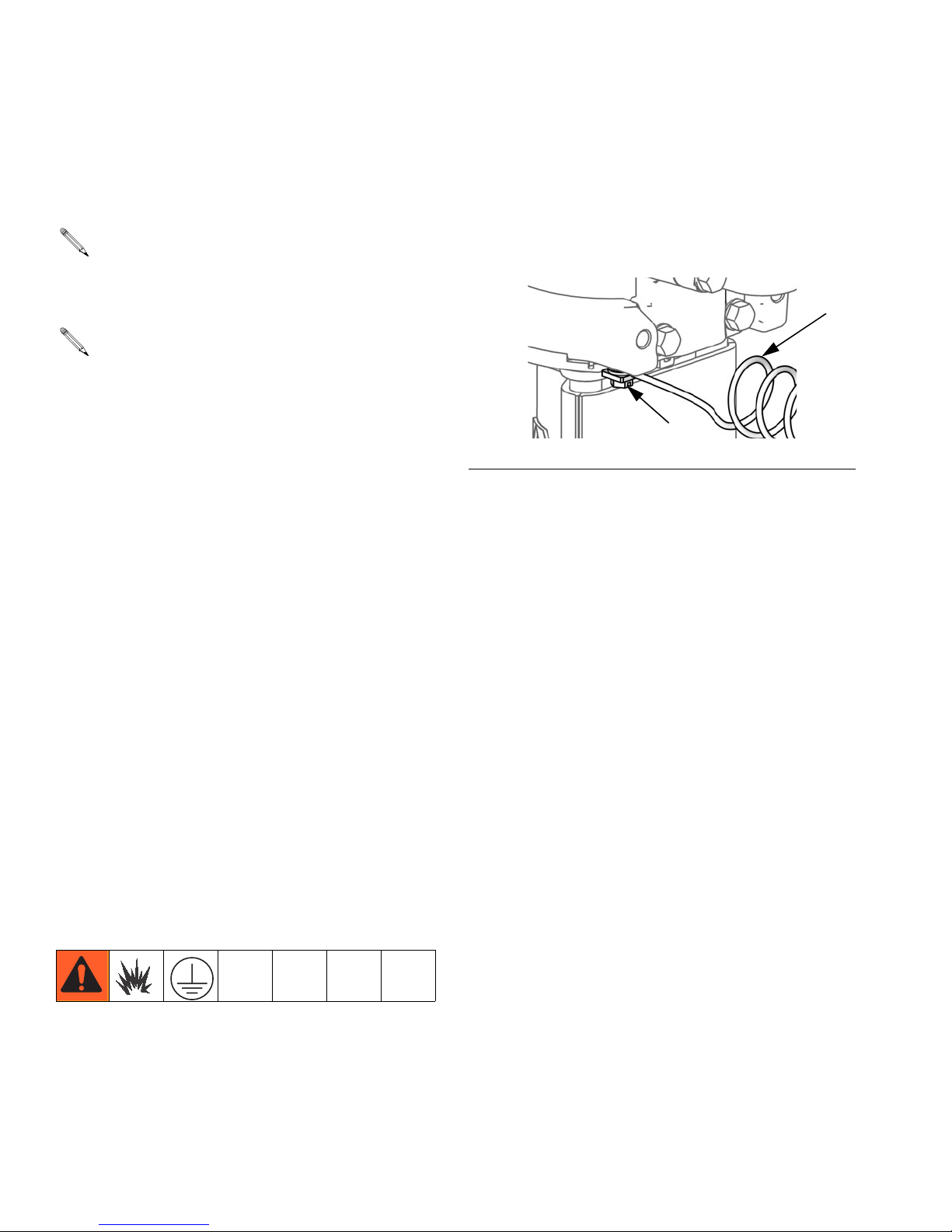
Prepare the Site
Pump: See F
attached and tightened securely to the air motor. Connect the other end of the ground wire (U) to a true earth
ground.
FIG. 2. Ground screw and wire
Air and fluid hoses: Static electricity may build up
when fluids flow through pumps, hoses, and sprayers. At
least one hose must be electrically conductive, with a
maximum of 500 ft. (150 m) combined hose length to
ensure grounding continuity. Check electrical resistance
of hose. If total resistance to ground exceeds 25 megohms, replace hose immediately.
IG. 2. Verify that the ground screw (GS) is
U
GS
ti12914a
Ensure that you have an adequate compressed air
supply.
Bring a compressed air supply line from the air compressor to the pump location. Be sure all air hoses are
properly sized and pressure-rated for your system. Use
only electrically conductive hoses.
Keep the site clear of any obstacles or debris that could
interfere with the operator's movement.
Have a grounded, metal pail available for use when
flushing the system.
Grounding
The equipment must be grounded. Grounding reduces
the risk of static and electric shock by providing an
escape wire for the electrical current due to static build
up or in the event of a short circuit.
Air compressor: follow manufacturer’s recommendations.
Spray gun / Dispense valve: Ground the spray gun
through connection to a Graco-approved grounded fluid
hose.
Fluid supply container: follow local code.
Object being sprayed: follow local code.
Solvent pails used when flushing: follow local code.
Use only conductive metal pails, placed on a grounded
surface. Do not place the pail on a nonconductive surface, such as paper or cardboard, which interrupts
grounding continuity.
To maintain grounding continuity when flushing or
relieving pressure: hold metal part of the spray
gun/dispense valve firmly to the side of a grounded
metal pail, then trigger the gun/valve.
8 312794F
Installation
Mount the Pump
Mount the pump only to Graco wall bracket 15T795, or
to a Graco cart, available from your distributor. Pump
dimensions are shown on page 29. For wall mounted
pumps, follow these guidelines:
1. Be sure the wall can support the weight of the
pump, bracket, hoses and accessories, as well as
the stress caused during operation.
2. Position the wall bracket about 1.2-1.5 m (4-5 ft)
above the floor. For ease of operation and service,
make sure the pump air inlet, fluid inlet, and fluid
outlet ports are easily accessible.
3. Using the wall bracket as a template, drill 10 mm
(0.4 in.) mounting holes in the wall. Wall mounting
dimensions are shown on page 30.
4. Attach the bracket to the wall. Use 9 mm (3/8 in.)
screws that are long enough to keep the pump from
vibrating during operation.
NOTE: Be sure the bracket is level.
• Pump air regulator (H): controls pump speed and
outlet pressure. Locate it close to the pump.
• Air line filter (B): removes harmful dirt and mois-
ture from compressed air supply.
• Air shutoff valve (A): isolates air line accessories
for servicing. Locate upstream from all other air line
accessories.
• Gun air regulator (D): controls air pressure to the
air-assisted spray gun.
Fluid Line
• Fluid filter (P): with a 60 mesh (250 micron) stain-
less steel element to filter particles from the fluid as
it leaves the pump.
• Fluid drain valve (W): required in your system, to
relieve fluid pressure in the hose and gun.
• Gun or valve (L): dispenses the fluid. The gun
shown in F
to medium viscosity fluids.
IG. 3 is an air-assisted spray gun for light
Air and Fluid Hoses
Be sure all air hoses (N) and fluid hoses (M) are properly sized and pressure rated for your system. See F
3. Use only electrically conductive fluid hoses.
IG.
Accessories
Install the following accessories in the order shown in
F
IG. 3, using adapters as necessary.
Air Line
• Bleed-type master air valve (E): required in your
system to relieve air trapped between it and the air
motor and gun when the valve is closed.
Trapped air can cause the pump to cycle unexpectedly,
which could result in serious injury from splashing or
moving parts.
• Fluid line swivel (K): for easier gun movement.
• Suction kit (V): enables the pump to draw fluid from
a container.
Be sure the valve is easily accessible from the pump
and located downstream from the air regulator.
312794F 9

Installation
Typical Installation
A Air Shutoff Valve
B Air Filter (optional accessory)
C Gun Air Pressure Gauge
D Gun Air Pressure Regulator
E Bleed Type Master Air Valve
F DataTrak
G Pump Air Pressure Gauge
H Pump Air Pressure Regulator
J Solenoid Release Button
(not visible)
KGun Swivel
L Air-Assisted Spray Gun
M Gun Fluid Supply Hose
N Gun Air Supply Hose
P Fluid Filter
R Pump Fluid Outlet
S Grounding Wire
T Wet-Cup (not visible, see F
U Pump Fluid Inlet
V Suction Hose
W Fluid Drain Valve
B
C
D
IG. 4, page 11)
A
F
G
G15 Spray Gun Shown
with Supply Hose
K
M
E
P
L
R
N
W
V
H
J
S
T
U
FIG. 3. Typical Installation. (Graco Cart-Mounted Package Shown.)
10 312794F
ti12800a
 Loading...