


XM6A00
Table of contents
 Loading...
Graco XM6A00, XM3A00, XM7A00, XM1B00, XM8A00 Operation Manual
...
Operation
™
XM
Plural-Component
312359J
Sprayers
For spraying two-component epoxy and urethane protective coatings in hazardous and
non-hazardous locations.
For professional use only.
EN
Important Safety Instructions
Read all warnings and instructions in this
manual. Save these instructions.
See page 7 for model information and agency approvals.
See page 84 for maximum working pressure.
ti21272a

Contents
Related Manuals . . . . . . . . . . . . . . . . . . . . . . . . . . . 3
Warnings . . . . . . . . . . . . . . . . . . . . . . . . . . . . . . . . . 4
Models . . . . . . . . . . . . . . . . . . . . . . . . . . . . . . . . . . . 7
Overview . . . . . . . . . . . . . . . . . . . . . . . . . . . . . . . . . . 9
Usage . . . . . . . . . . . . . . . . . . . . . . . . . . . . . . . . . 9
Isocyanate Hazard . . . . . . . . . . . . . . . . . . . . . . . 9
Material Self-Ignition . . . . . . . . . . . . . . . . . . . . . . 9
Moisture Sensitivity of Isocyanates . . . . . . . . . . . 9
Components A and B . . . . . . . . . . . . . . . . . . . . 10
Changing Materials . . . . . . . . . . . . . . . . . . . . . . 10
Location . . . . . . . . . . . . . . . . . . . . . . . . . . . . . . . . . 11
Grounding . . . . . . . . . . . . . . . . . . . . . . . . . . . . . 11
Proper Lifting of Sprayer . . . . . . . . . . . . . . . . . . . 11
Initial System Setup . . . . . . . . . . . . . . . . . . . . . . . 12
Component Identification . . . . . . . . . . . . . . . . . . . 13
Typical Setup: 20 Gallon Hoppers with Recirculation
(Front View) . . . . . . . . . . . . . . . . . . . . . . . . 13
Typical Setup: 20 Gallon Hoppers with Recirculation
(Back View) . . . . . . . . . . . . . . . . . . . . . . . . . 14
Fluid Control Assembly . . . . . . . . . . . . . . . . . . . 15
Junction Box/Heater Controls . . . . . . . . . . . . . . 16
Air Controls . . . . . . . . . . . . . . . . . . . . . . . . . . . . 16
User Interface . . . . . . . . . . . . . . . . . . . . . . . . . . 17
Setup . . . . . . . . . . . . . . . . . . . . . . . . . . . . . . . . . . . . 19
Connect Power Cord . . . . . . . . . . . . . . . . . . . . . 19
Configure to Supply Power . . . . . . . . . . . . . . . . 20
Wire Sprayers with Explosion-Proof Heaters . . 21
Connect Air Supply . . . . . . . . . . . . . . . . . . . . . . 21
Connect Fluid Hose Assembly . . . . . . . . . . . . . 22
Adjust Packing Nuts . . . . . . . . . . . . . . . . . . . . . 22
Basic Operation . . . . . . . . . . . . . . . . . . . . . . . . . . . 23
Power On (Alternator Power Supplied Systems) 23
Power On (Wall Power Supplied Systems) . . . . 23
Adjust Ratio and Setup . . . . . . . . . . . . . . . . . . . 23
Final Setup . . . . . . . . . . . . . . . . . . . . . . . . . . . . 23
View Alarms . . . . . . . . . . . . . . . . . . . . . . . . . . . 23
Set System Settings (Optional) . . . . . . . . . . . . . 24
Set Maintenance Parameters (Optional) . . . . . . 25
Set Sprayer Limits (Optional) . . . . . . . . . . . . . . 26
Prime . . . . . . . . . . . . . . . . . . . . . . . . . . . . . . . . . . . . 27
Prime A and B Fluids . . . . . . . . . . . . . . . . . . . . 27
Prime Solvent Flush Pump . . . . . . . . . . . . . . . . 29
Recirculate . . . . . . . . . . . . . . . . . . . . . . . . . . . . . . . 30
Without Heat . . . . . . . . . . . . . . . . . . . . . . . . . . . 30
With Heat . . . . . . . . . . . . . . . . . . . . . . . . . . . . . 31
Heat Fluid . . . . . . . . . . . . . . . . . . . . . . . . . . . . . 31
Spray . . . . . . . . . . . . . . . . . . . . . . . . . . . . . . . . . . . . 32
Adjust B Machine Outlet Restriction . . . . . . . . . . 33
Pressure Relief Procedure . . . . . . . . . . . . . . . . . . 34
Flush Mixed Material . . . . . . . . . . . . . . . . . . . . . . . 36
Park Fluid Pump Rods . . . . . . . . . . . . . . . . . . . . . . 38
Shutdown Entire System . . . . . . . . . . . . . . . . . . . . 39
System Verification . . . . . . . . . . . . . . . . . . . . . . . . 40
Mix and Integration Tests . . . . . . . . . . . . . . . . . . 40
Pump and Metering Test . . . . . . . . . . . . . . . . . . 40
Batch Ratio Dispense Test . . . . . . . . . . . . . . . . 43
Down Stream Valve Leak Test . . . . . . . . . . . . . . 44
XM Setup and Troubleshooting Guide . . . . . . . . 45
Empty and Flush Entire System
(new sprayer or end of job) . . . . . . . . . . . . . . 46
Download Data from USB . . . . . . . . . . . . . . . . . . . 48
USB Logs . . . . . . . . . . . . . . . . . . . . . . . . . . . . . 48
Download Setup . . . . . . . . . . . . . . . . . . . . . . . . 48
Download Procedure . . . . . . . . . . . . . . . . . . . . . 48
Maintenance . . . . . . . . . . . . . . . . . . . . . . . . . . . . . . 50
Filters . . . . . . . . . . . . . . . . . . . . . . . . . . . . . . . . . 50
Seals . . . . . . . . . . . . . . . . . . . . . . . . . . . . . . . . . 50
Cleaning Procedure . . . . . . . . . . . . . . . . . . . . . . 50
Alarms . . . . . . . . . . . . . . . . . . . . . . . . . . . . . . . . . . . 51
View Alarms . . . . . . . . . . . . . . . . . . . . . . . . . . . . 51
Diagnose Alarms . . . . . . . . . . . . . . . . . . . . . . . . 51
Clear Alarms . . . . . . . . . . . . . . . . . . . . . . . . . . . 51
Alarm Codes and Troubleshooting . . . . . . . . . . 52
LED Diagnostic Information . . . . . . . . . . . . . . . . 58
Accessories and Kits . . . . . . . . . . . . . . . . . . . . . . . 59
Appendix A . . . . . . . . . . . . . . . . . . . . . . . . . . . . . . . 61
User Interface Display . . . . . . . . . . . . . . . . . . . . 61
Setup Mode Screens . . . . . . . . . . . . . . . . . . . . . 62
Operator Command Functions Screens . . . . . . 69
Auto Display Screens . . . . . . . . . . . . . . . . . . . . 75
Appendix B . . . . . . . . . . . . . . . . . . . . . . . . . . . . . . . 77
Metering Diagrams . . . . . . . . . . . . . . . . . . . . . . 77
Appendix C . . . . . . . . . . . . . . . . . . . . . . . . . . . . . . . 79
Power Cord Guidelines . . . . . . . . . . . . . . . . . . . 79
Dimensions . . . . . . . . . . . . . . . . . . . . . . . . . . . . . . . 80
System Dimensions without Hoppers . . . . . . . . 80
System Dimensions with Hoppers . . . . . . . . . . . 81
System Dimensions with Hoppers . . . . . . . . . . . 82
Pump Performance Charts . . . . . . . . . . . . . . . . . . 83
Technical Data . . . . . . . . . . . . . . . . . . . . . . . . . . . . 84
Graco Standard Warranty . . . . . . . . . . . . . . . . . . . 86
Graco Information . . . . . . . . . . . . . . . . . . . . . . . . . 86
2 312359J

Related Manuals
Manuals are available at www.graco.com.
Component Manuals in U.S. English:
Manual Description
313289
313292
311762
311238
312747
309524
312145
312769
312794
406699
406739 Desiccant Kit Instructions-Parts
406690 Caster Kit Instructions-Parts
XM Plural-Component Sprayers
Repair-Parts
XM Plural-Component OEM Sprayers
Instructions-Parts
®
Xtreme
Displacement Pumps
Instructions-Parts
™
NXT
Air Motor Instructions-Parts
Double Wall Hopper Kit
Instructions-Parts
®
Viscon
XTR
HP Heater Instructions-Parts
™
5 and XTR™ 7 Spray Guns
Instructions-Parts
Feed Pump and Agitator Kits
Instructions-Parts
®
Merkur
Pump Assembly
Instructions-Parts
7-Gallon Hopper Installation Kit
Instructions-Parts
Related Manuals
406691 Hose Rack Kit Instructions-Parts
313258
313259
312770
312749
313293
313342
313343
Electric Heated Hose Power Supply Kit
Instructions-Parts
Hopper or Hose Heat Circulation Kit
Instructions-Parts
Lower Strainer and Valve Kit
Instructions-Parts
XM Mix Manifold Kit
Instructions-Parts
Alternator Conversion Kits
Instructions-Parts
Dosing Valve Repair Kit
Instructions-Parts
High Flow Severe Duty Shutoff Check
Valve Repair Kit Instructions-Parts
312359J 3

Warnings
Warnings
The following warnings are for the setup, use, grounding, maintenance, and repair of this equipment. The exclamation point symbol alerts you to a general warning and the hazard symbol refers to procedure-specific risk. Refer back
to these warnings. Additional, product-specific warnings may be found throughout the body of this manual where
applicable.
WARNING
WARNINGWARNINGWARNING
FIRE AND EXPLOSION HAZARD
Flammable fumes, such as solvent and paint fumes, in work area can ignite or explode. To help prevent
fire and explosion:
• Use equipment only in well ventilated area.
• Eliminate all ignition sources; such as pilot lights, cigarettes, portable electric lamps, and plastic drop
cloths (potential static arc).
• Keep work area free of debris, including solvent, rags and gasoline.
• Do not plug or unplug power cords, or turn power or light switches on or off when flammable fumes
are present.
• Ground all equipment in the work area. See Grounding instructions.
• Use only grounded hoses.
• Hold gun firmly to side of grounded pail when triggering into pail.
• If there is static sparking or you feel a shock, stop operation immediately. Do not use equipment
until you identify and correct the problem.
• Keep a working fire extinguisher in the work area.
• Do not connect USB device in explosive atmospheres.
SPECIAL CONDITIONS FOR SAFE USE
• To prevent the risk of electrostatic sparking, the equipment’s non-metallic parts must be cleaned with
only a damp cloth.
• Refer to the Viscon HP Heater manual for special conditions for safe use.
ELECTRIC SHOCK HAZARD
Improper grounding, setup, or usage of the system can cause electric shock.
• Turn off and disconnect power at main switch before disconnecting any cables and before servicing
equipment.
• Connect only to grounded power source.
• All electrical wiring must be done by a qualified electrician and comply with all local codes and
regulations.
4 312359J
Warnings
WARNING
INTRINSIC SAFETY
Intrinsically safe equipment that is installed improperly or connected to non-intrinsically safe equipment
will create a hazardous condition and can cause fire, explosion, or electric shock. Follow local regulations and the following safety requirements.
• Only models with model number XM_D_ _ or XM_E_ _, and packaged models with part numbers
ending in 00-13, 17-23, 27-29, 31, utilizing the air-driven alternator are approved for installation in a
Hazardous (explosive atmosphere) Location - see Approvals:, page 8. Only the models stated
above meet all local safety fire codes including NFPA 33, NEC 500 and 516, and OSHA 1910.107.
To help prevent fire and explosion:
• Do not install equipment approved only for a non-hazardous location in a hazardous location.
See model ID label for intrinsic safety rating of your model.
• Do not substitute system components as this may impair intrinsic safety.
• Equipment that comes in contact with the intrinsically safe terminals must be rated for Intrinsic
Safety. This includes DC voltage meters, ohmmeters, cables, and connections. Remove the unit
from the hazardous area when troubleshooting.
• Do not connect, download, or remove USB device unless unit is removed from the hazardous (explosive atmosphere) location.
• If explosion-proof heaters are used, ensure wiring, wiring connections, switches, and electrical distribution panel all meet flame-proof (explosion-proof) requirements.
SKIN INJECTION HAZARD
High-pressure fluid from gun, hose leaks, or ruptured components will pierce skin. This may look like just
a cut, but it is a serious injury that can result in amputation. Get immediate surgical treatment.
• Do not point gun at anyone or at any part of the body.
• Do not put your hand over the spray tip.
• Do not stop or deflect leaks with your hand, body, glove, or rag.
• Do not spray without tip guard and trigger guard installed.
• Engage trigger lock when not spraying.
•Follow Pressure Relief Procedure in this manual, when you stop spraying and before cleaning,
checking, or servicing equipment.
PRESSURIZED EQUIPMENT HAZARD
Fluid from the gun/dispense valve, leaks, or ruptured components can splash in the eyes or on skin and
cause serious injury.
•Follow Pressure Relief Procedure in this manual, when you stop spraying and before cleaning,
checking, or servicing equipment.
• Tighten all fluid connections before operating the equipment.
• Check hoses, tubes, and couplings daily. Replace worn or damaged parts immediately.
MOVING PARTS HAZARD
Moving parts can pinch or amputate fingers and other body parts.
• Keep clear of moving parts.
• Do not operate equipment with protective guards or covers removed.
• Pressurized equipment can start without warning. Before checking, moving, or servicing equipment,
follow the Pressure Relief Procedure in this manual. Disconnect power or air supply.
312359J 5

Warnings
WARNING
EQUIPMENT MISUSE HAZARD
Misuse can cause death or serious injury.
• Do not operate the unit when fatigued or under the influence of drugs or alcohol.
• Do not exceed the maximum working pressure or temperature rating of the lowest rated system
component. See Technical Data in all equipment manuals.
• Use fluids and solvents that are compatible with equipment wetted parts. See Technical Data in all
equipment manuals. Read fluid and solvent manufacturer’s warnings. For complete information
about your material, request MSDS forms from distributor or retailer.
• Check equipment daily. Repair or replace worn or damaged parts immediately with genuine manufacturer’s replacement parts only.
• Do not alter or modify equipment.
• Use equipment only for its intended purpose. Call your distributor for information.
• Route hoses and cables away from traffic areas, sharp edges, moving parts, and hot surfaces.
• Do not kink or over bend hoses or use hoses to pull equipment.
• Keep children and animals away from work area.
• Comply with all applicable safety regulations.
TOXIC FLUID OR FUMES HAZARD
Toxic fluids or fumes can cause serious injury or death if splashed in the eyes or on skin, inhaled, or
swallowed.
• Read MSDS’s to know the specific hazards of the fluids you are using.
• Store hazardous fluid in approved containers, and dispose of it according to applicable guidelines.
• Always wear impervious gloves when spraying or cleaning equipment.
BURN HAZARD
Equipment surfaces and fluid that’s heated can become very hot during operation. To avoid severe
burns, do not touch hot fluid or equipment. Wait until equipment/fluid has cooled completely.
PERSONAL PROTECTIVE EQUIPMENT
You must wear appropriate protective equipment when operating, servicing, or when in the operating
area of the equipment to help protect you from serious injury, including eye injury, inhalation of toxic
fumes, burns, and hearing loss. This equipment includes but is not limited to:
• Protective eyewear
• Clothing and respirator as recommended by the fluid and solvent manufacturer
•Gloves
• Hearing protection
6 312359J

Models
Models
XM sprayers are not approved for use in hazardous
locations unless the base model, all accessories, all
kits, and all wiring meet local, state, and national
codes.
Check the identification plate (ID) for the 6-digit part number of the sprayer. Use the following matrix to define the
construction of the sprayer, based on the six digits. For example, Part XM1A00 represents an XM Plural-Component
sprayer (XM); 5200 psi pump set with pump filters (1); wall power supply, no heaters, no junction box, and is not
approved for hazardous areas (A); with no additional kits (00).
NOTE:
Some configurations in the following matrix cannot be built. Consult with distributor or Graco representative.
To order replacement parts, see Parts section the XM Plural-Component Sprayer Repair-Parts manual 313289. The
digits in the matrix do not correspond to the Ref. Nos. in the Parts drawings and lists.
XM 1 A
First and
Second
Digits
XM
(plural com-
ponent
sprayer
mounted
on a frame)
(See Table 1 for lower models) Kit Choice
Pump Set
(hose/gun)
1 5200 psi
2 5200 psi B
3 6300 psi
4 6300 psi D
5 5200 psi
6 5200 psi
7 6300 psi
8 6300 psi
Third Digit Fourth Digit
System Choice
Pump
Filters
✔
✔
✔✔
✔✔
Remote
Manifold
✔
✔
Control
Box
Wall Power
A
Supply NE
Wall Power
Supply
Wall Power
C
Supply
IS/
Alternator EH
IS/
E
Alternator
Fluid
Heaters
Location Category Key:
Junction
Box
✔✔
✔
✔
Location
Category
Approvals
(see page 8
for approvals
CE, FM,
FMc
NE CE, FM,
c
FM
NE CE, FM,
FMc
CE, FM,
FMc, Ex
EH
CE, FM,
FMc, Ex
00
Fifth and
Sixth
Digits
Additional
Kit
See Table
2 for
)
selections
NE Not for use in explosive atmospheres.
EH For use in explosive atmospheres and hazardous
locations
312359J 7
.

Models
Approvals:
See appropriate column on page 7.
XM _ A_ _
XM _ B_ _
XM _ C_ _
XM _ D_ _
XM _ E_ _
Intrinsically safe for Class I, Div 1, Group D, T2
Class I, Division 1, Group D, T2
Ta = 0°C to 54°C
See Special Conditions for Safe Use in Warnings, page 4.
FM09ATEX0015X
II 2 G
Ex d ia px IIA T2 Tamb = 0ºC to 54ºC
Table 1: Lower Models and Corresponding Identification Codes
System Pressure
Code
(MPa, bar)
1 or 5 5200 psi (35, 350)
Pump
Filters
✔
A Lower
(see manual 311762)
L250C4 L220C4
B Lower
(see manual 311762)
2 or 6 5200 psi (35, 350) L250C3 L220C3
3 or 7 6300 psi (49, 490)
✔
L180C4 L145C4
4 or 8 6300 psi (49, 490) L180C3 L145C3
Table 2: Additional Kits - Identification Code/Part No. Index
7 Gal.
Hopper
Hopper
20 Gal.
Hopper
Kit
00
11 1111 1
13 11111
14 11111 1
15 11 11 1 1
16 11 11 11
17 1111 1 1
19 11111 1
21 2222
23 2222
24 22222
25 22 22 2
26 22 22 2
27 2222 1
29 2222 1
30 2
31 2
32 11
Hopper
Heater
Kit 240V
Hopper
Fluid
Inlet Kit
Universal
Mount
Kit
Twi stork
Agitator
Kit
T2 Pump
Feed Kit
(on
hopper)
5:1 Pump
Feed Kit
(on
hopper)
(Green)
and
Bracket
Kit
7 Gal.
Hopper
(Blue)
and
Bracket
Kit
Drum
Feed Kit
(Dual T2
and
Agitator)
Drum
Feed Kit
(Dual 5:1
and
Agitator)
Heated
Hopper/
Hose
Circulation
Kit
NOTE:
See Accessories and Kits, page 59, for more information.
See Related Manuals, page 3, for kit manual numbers.
8 312359J

Overview
Overview
Usage
XM plural-component sprayers can mix and spray most
two-component epoxy and urethane protective coatings.
When using quick-setting materials (less than 10 minute
pot life) a remote mix manifold must be used.
XM plural-component sprayers are operated via the user
interface, air controls, and fluid controls.
XM sprayers are not approved for use in hazardous
locations unless the base model, all accessories, all
kits, and all wiring meet local, state, and national
codes. See Models, page 7, to determine the appropriate location for your particular sprayer model.
Isocyanate Hazard
Spraying materials containing isocyanates creates
potentially harmful mists, vapors, and atomized particulates.
Material Self-Ignition
Some materials may become self-igniting if applied
too thick. Read material manufacturer’s warnings and
material MSDS.
Moisture Sensitivity of Isocyanates
Isocyanates (ISO) are catalysts used in two component
urethane coatings. ISO will react with moisture (such as
humidity) to form small, hard, abrasive crystals, which
become suspended in the fluid. Eventually a film will
form on the surface and the ISO will begin to gel,
increasing in viscosity. If used, this partially cured ISO
will reduce performance and the life of all wetted parts.
NOTE:
The amount of film formation and rate of crystallization
varies depending on the blend of ISO, the humidity, and
the temperature.
To prevent exposing ISO to moisture:
Read material manufacturer’s warnings and material
MSDS to know specific hazards and precautions
related to isocyanates.
Prevent inhalation of isocyanate mists, vapors, and
atomized particulates by providing sufficient ventilation in the work area. If sufficient ventilation is not
available, a supplied-air respirator is required for
everyone in the work area.
To prevent contact with isocyanates, appropriate personal protective equipment, including chemically
impermeable gloves, boots, aprons, and goggles, is
also required for everyone in the work area.
• Always use a sealed container with a desiccant
dryer in the vent, or a nitrogen atmosphere. Never
store ISO in an open container.
• Use moisture-proof hoses specifically designed for
ISO, such as those supplied with your system.
• Never use reclaimed solvents, which may contain
moisture. Always keep solvent containers closed
when not in use.
• Never use solvent on one side if it has been contaminated from the other side.
• Always park pumps when you shutdown.
• Always lubricate threaded parts with Part 217374
ISO pump oil or grease when reassembling.
312359J 9

Overview
Components A and B
IMPORTANT!
Material suppliers can vary in how they refer to plural
component materials.
Be aware that in this manual:
Component A refers to resin or major volume.
Component B refers to the hardener or minor volume.
NOTE:
This equipment doses the B component into the A component flow. An integration hose must always be used
after the mix manifold and before the static mixer.
NOTE:
Follow these recommendations for setup:
• use at least a 3/8 in. (10 mm) x 25 ft. (7 m) hose as
the integration hose.
• install a 24-element static mix tube after the integration hose.
Changing Materials
• When changing materials, flush the equipment multiple times to ensure it is thoroughly clean.
• Always clean the fluid inlet strainers and outlet filter
after flushing, Flush Mixed Material, page 36.
• Check with your material manufacturer for chemical
compatibility.
• Epoxies often have amines on the B (hardener)
side. Polyureas often have amines on the A (resin)
side.
NOTE:
If the amine will switch between the two sides, see
Flush Mixed Material, page 36.
Keep Components A and B Separate
NOTICE
To prevent cross-contamination of the equipment’s wetted parts, never interchange component A (resin) and
component B (hardener) parts.
10 312359J
Location
Location
XM sprayers are not approved for use in hazardous
locations unless the base model, all accessories, all
kits, and all wiring meet local, state, and national
codes. See ModelsModels, page 7, to determine the
appropriate location for your particular sprayer model.
Grounding
Connect the XM sprayer ground wire clamp (FG) to a
true earth ground. If wall power is used to power controls or heaters, ground electrical connection properly
according to local codes.
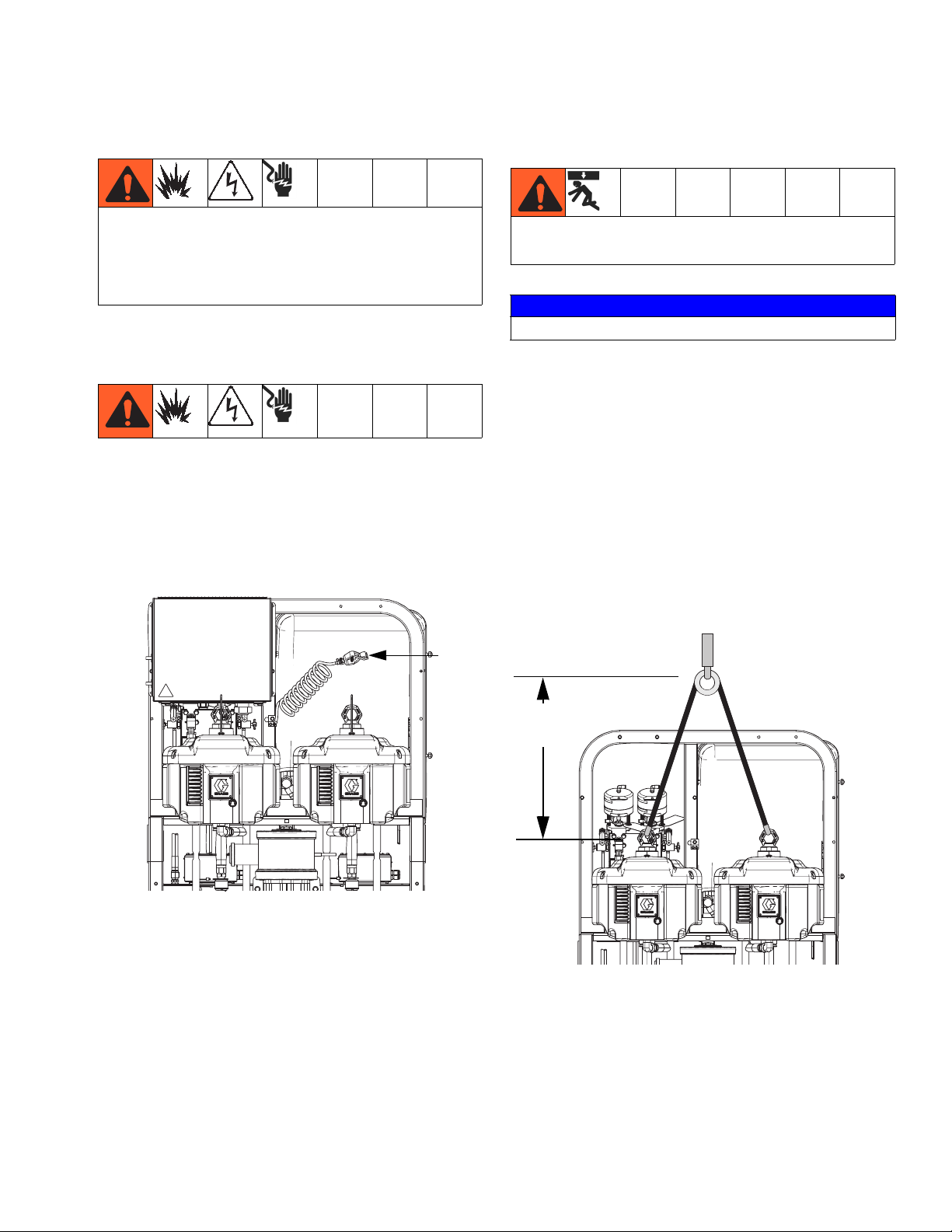
Proper Lifting of Sprayer
Follow instructions to avoid serious injury or damage
to equipment. Never lift with the hopper(s) filled.
NOTICE
Drain all fluid prior to lifting sprayer.
Lift Using a Forklift
Power must be off. Sprayer can be raised and moved
using a forklift. Carefully lift the sprayer; make sure it
balances evenly.
Lift Using a Hoist
Sprayer can also be lifted and moved using a hoist. Connect a bridle swing, hooking an end to each of the air
motor lift rings. Hook the center ring to a hoist. See the
following figure. Carefully lift the sprayer; make sure it
balances evenly.
ti21273a
FG
2.0 ft. (0.61 m)
minimum
ti21274a
312359J 11

Initial System Setup
Initial System Setup
Complete the following steps in the order they are listed,
as they apply to your specific system, for initial system
setup.
1. Check your shipment for accuracy. Ensure you have
received everything you ordered. See Component
Identification, page 13, to familiarize yourself with
typical system components.
2. Mount caster kit, if ordered. See manual 406690 for
instructions.
3. Mount hopper brackets, if ordered. See manual
312747 for instructions.
4. Loosely mount hoppers, if ordered, on brackets. See
manual 312747 for instructions.
5. Connect bottom hopper outlet if using a gravity feed
pump. See manual 312747 for instructions.
6. Tighten hopper mounting bolts. See manual 312747
for instructions.
7. Mount and connect agitator(s) and feed pump(s), if
ordered. See manual 312769 for instructions.
15. For hazardous location sprayers, connect explosion-proof heaters. See Wire Sprayers with Explo-
sion-Proof Heaters, page 21, and manual 309524
for instructions and recommendations.
16. Connect air supply line. See Connect Air Supply,
page 21, for instructions and recommendations.
17. Connect fluid hose assembly, including whip hose
and gun. See Connect Fluid Hose Assembly,
page 22, for instructions. Also connect remote mix
manifold, if ordered. See manual 312749 for instructions.
8. Mount and connect hopper immersion heater kit, if
ordered. See manual 312747 for instructions.
9. Connect recirculation hose, restrictor valve (including knob and nipple), and recirculation tube. Place
in hopper or drum. See manual 312747 for instructions.
10. Replace USB label (front of control panel) with correct language version, if needed.
11. Replace Alarms Codes label (under fluid control
valves) with correct language version, if needed.
12. Install hopper/hose heated circulation kit, if ordered.
See manual 313259 for instructions.
13. For non-hazardous location sprayers, connect
power cord (not supplied). See Connect Power
Cord, page 19, for instructions.
14. For non-hazardous location sprayers, connect junction box wiring for immersion or recirculation heaters. See manual 312747 for immersion heater
instructions. See manual 309524 for recirculation
heater instructions.
12 312359J
Component Identification
Component Identification
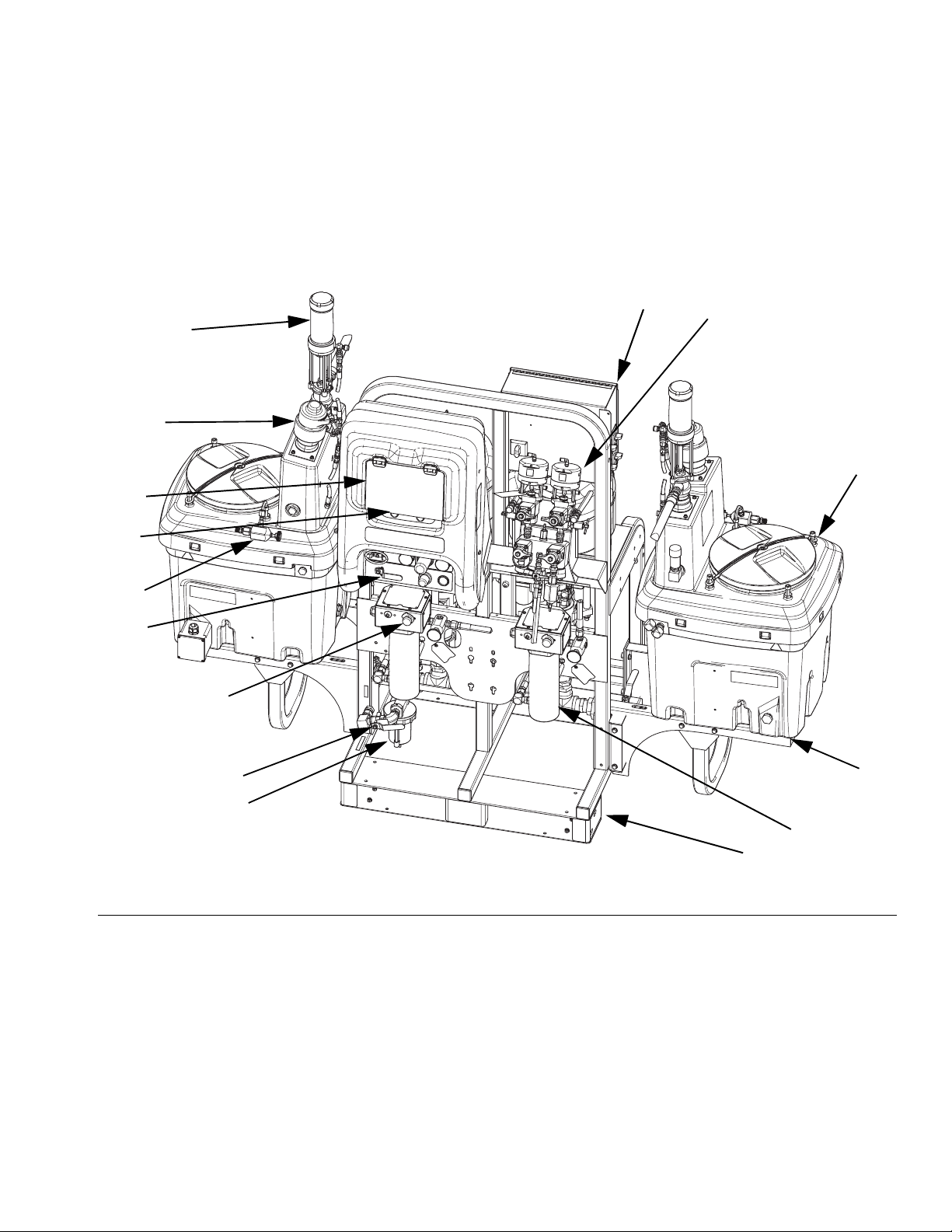
Typical Setup: 20 Gallon Hoppers with Recirculation (Front View)
L
P
N
F
G
R
J
B
C
M
E
H
K
A
D
ti21272a
FIG. 1: Typical Setup: 20 Gallon Hoppers with Recirculation (Front View)
AFrame
B Fluid Control Assembly (see Fluid Control Assembly,
page 15)
C 20 Gallon Hopper Assembly (see manual 312747)
D 20 Gallon Hopper Bracket (see manual 312747)
E Main Air Valve
F GCA Control Display (see User Interface Display, page
18)
312359J 13
G Pump Control On and Off Buttons
H Air Filter
J Air Controls
K Viscon HP Fluid Heater
L Junction Box/Heater Controls (see Junction Box/Heater
Controls, page 16)
M Inline Fluid Heater Control
N Air Powered Agitator
P Pressure Feed Pump
R Recirculation Control Valve

Component Identification
Typical Setup: 20 Gallon Hoppers with Recirculation (Back View)
S
T
FIG. 2: Typical Setup: 20 Gallon Hoppers with Recirculation (Back View)
S Air Motor
T High Pressure Fluid Pump
U Solvent Flush Pump (Merkur
V Fluid Inlet Assembly
®
Pump)
U
V
14 312359J

Fluid Control Assembly
Component Identification
AC
AL
AE
AH
AA
AB
AD
AF
AG
AM
AJ
AK
r_XM1A00_312359_313289_18A
FIG. 3: Fluid Control Assembly
AA Dosing Valve A
AB Dosing Valve B
AC Recirculation Valve A
AD Recirculation Valve B
AE Sampling Valve A
312359J 15
AF Sampling Valve B
AG Restriction Valve
AH Mix Manifold Shutoff / Check Valve A
AJ Mix Manifold Shutoff / Check Valve B
AK Solvent Shutoff Valve
AL Pressure Sensor
AM Solvent Check Valve

Component Identification
Junction Box/Heater Controls
BA
FIG. 4: Junction Box/Heater Controls
BB
BC
BE
BD
BA Main Power Disconnect Switch
BB Fluid Heater A Control
BC Fluid Heater B Control
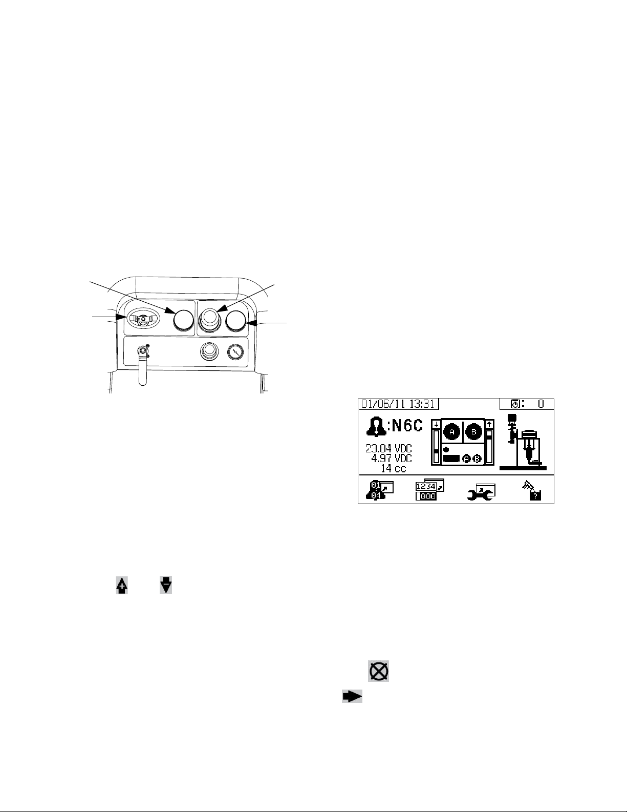
Air Controls
CA
CB
FIG. 5: Air Controls
BD Hopper Heater A Control
BE Hopper Heater B Control
CC
CD
CE
CF
CG
r_XM1A00_312359_313289_14A
CA Main Pump and Air On/Off Control
CB Solvent Pump Air On/Off Control
CC Inlet Air Pressure Gauge
CD Main Pump Air Regulator
16 312359J
CE Main Pump Air Regulator Gauge
CF Solvent Pump Air Gauge
CG Solvent Pump Air Regulator

User Interface
Component Identification
DJ
IG. 6: User Interface
F
DR
DA
DG
DF
DD
DM
DB
Buttons LEDs
DK
DC
ti13365a
DN
DH
DE
DP
Call
out Button Function
DA Display
Screen
DB Start Initiates Active Run Mode function cur-
DC Stop Terminates Active Run Mode function
DD Enter Press to open drop-down fields, selection
DE Alarm
Reset
DF Left/Right Move between screens in run or setup
DG Function Activates mode or action represented by
DH Up/Down Move between selection boxes,
DJ Setup Key
Lock
DR USB Port Connection for data download. Use only
Use to view Ratio, Mode Selection, Error
Conditions, Totalizers, System Information.
rently selected in Run Screen.
currently selected.
options, and save values.
Resets alarms and advisories.
modes.
the icon above each of the four buttons in
the LCD.
drop-down fields, and selectable values
within Setup screens.
Change ratio or enter Setup mode.
in non-hazardous locations.
There are four types of LEDs on the display.
Call
out LED Function
DK Blue Dosing valve active
• on - dosing valve is active
• off - dosing valve is not active
DM Green Spray mode active
• spray mode is on (active)
• spray mode is off (inactive)
DN Red Alarm
• on - alarm is present
• off - no alarm
DP Yellow Warning
• on - is active.
• off - no warning indicated. Ratio
and setup fields are not changeable.
• flashing - key is present and
turned. Ratio and setup fields
are changeable.
312359J 17

Component Identification
User Interface Display
NOTE:
For details regarding the user interface display see User
Interface Display, page 61.
Main Display Screen Components
The following figure calls out the navigational, status, and general informational components of each display screen.
Current Date and Time
Current Status Bar
Navigate to screens
within same group
Navigational Bar
F
IG. 7: Main Display Screen Components (shown with all display features enabled)
Remaining Potlife Time
Function Display
Go back one screen
NOTICE
To prevent damage to soft key buttons, do not press
the buttons with sharp objects such as pens, plastic
cards, or fingernails.
18 312359J

Setup
Setup
Connect Power Cord
(For sprayers with heater junction boxes.
Non-hazardous location sprayers only.)
Graco does not supply heater junction box power cords.
Use the following chart to determine which power cord
your specific model requires.
Power Cord Requirements
2
Voltage Cord Specification AWG (mm
240V, 1 PH 4 (21.2) 2 wire + ground
240V, 3 PH 6 (13.3) 3 wire + ground
380V, 3 PH 6 (13.3) 4 wire + ground
NOTE:
Sprayers without heaters for non-hazardous locations
include a U.S. style NEMA 5-15 power cord and an
IEC-320 power cord. (European and Australian adapters
are also included.) These power cords are rated for
90-240 Vac, 47-63 Hz. See the XM Plural-Component
Sprayers Repair-Parts manual or the XM Plural-Component OEM Sprayers Instructions-Parts manual for part
numbers.
)
230V, 1 Phase: Use a screwdriver to connect two power
leads to the top terminals N and L2 positions. Connect
green to ground (GND).
L2
L1
7L4
L1 L2 L3N
1L1
ti8611a
123N
L1
N
PE
GRND
G
L3
L2
230V, 3 Phase Delta: Use a screwdriver to connect
three power leads to top terminals L1, L2, and L3. Connect green to ground (GND).
PE
L3
L2
L1
L1 L2 L3N
1L1
ti8612a
123N
GRND
G
L3
L1
N
L2
380V, 3 Phase WYE: Use a screwdriver to connect three
power leads to the top terminals L1, L2, and L3. Connect
neutral to N. Connect green to ground (GND).
NOTE:
Disregard terminal numbers on disconnect switch
blocks. Wire to positions shown.
1. Open junction box cover.
N
7L4
L1 L2 L3
1L1
ti8613a
L1N
123N
GRND
G
L3
L1
N
L2
PE
L3
L2
2. Connect electrical cord as follows.
312359J 19

Setup
Configure to Supply Power
(Non-hazardous location sprayers only.)
NOTE:
Disregard terminal numbers on disconnect switch
blocks. Wire to positions shown.
1. Locate power jumpers.
2. Use a flat-blade screwdriver to move red jumpers
from storage positions to positions for your power as
shown below. Push jumpers firmly into new position.
NOTE:
For 230V, 1 Phase and 230V, 3 Phase Installations,
change jumper positions as shown below. Machine is
shipped with jumpers in the fail-safe 380 3Ø position.
3. Close junction box cover.
TB2
Terminal Blocks
Position red jumpers
as shown
ti18664a
L3
L2
L1
N
380V 3ø WYE
(as shipped)
Power
Jumpers
N
L1
L2
L3
230V 3ø Delta
N
L1
L2
230V 1ø
L3
20 312359J

Setup
Wire Sprayers with Explosion-Proof Heaters
(Hazardous location sprayers only)
If your sprayer is rated for hazardous areas, and you
have explosion-proof heaters, you must have a qualified electrician connect heater wiring. Ensure wiring
and installation comply with local electrical codes for
hazardous areas.
Improperly installed or connected equipment will create
a hazardous condition and cause fire, explosion, or electric shock. Follow local regulations.
When explosion-proof heaters are used, ensure wiring,
wiring connections, switches, and electrical distribution
panel all meet flame-proof (explosion-proof) requirements.
Refer to Viscon HP heater manual 309524 for electrical
connection instructions and guidelines in hazardous
locations.
Connect Air Supply
Connect air supply line to 3/4 npt(f) air filter inlet.
NOTE:
Use a 3/4 in. (19.1 mm) ID minimum air hose.
E
NOTE:
Air supply requirement: 150 psi (1.0 MPa, 10.3 bar)
maximum; 50 psi (0.35 MPa, 3.5 bar) minimum (while
running).
Flow volume required: 70 scfm (1.96 m
250 scfm (7.0 m
sure and flow rate are directly related to available air volume. See Pump Performance Charts, page 83.
3
/min) maximum. Available fluid pres-
3
/min) minimum;
General flow volume guidelines:
• 70 scfm (1.96 m
spraying
• 10 scfm (0.28 m
• 10 scfm (0.28 m
pump
NOTE:
If your sprayer is for use in hazardous areas, the control
box is powered by an air-driven alternator.
NOTE:
Dosing valves are operated by air. The sprayer will not
operate correctly if the inlet air gauge drops below 50
psi (0.35 MPa, 3.5 bar) while spraying.
3
/min) per gpm (lpm) while
3
/min) added per agitator
3
/min) added per drum feed
312359J 21

Setup
Connect Fluid Hose Assembly
1. Connect fluid hose to fluid manifold outlet. Do not
install gun spray tip yet.
Fluid
Integrator
Hose
NOTICE
Do not assemble static mixer directly to the fluid manifold. Install static mixer after first 25 ft. (7.5 m) of integrator hose to ensure material doses are completely
integrated. Spraying poorly integrated material could
require rework of parts sprayed.
2. Tighten all fittings.
Adjust Packing Nuts
1. Fill A and B pump packing nuts with throat seal liq-
™
uid (TSL
low instructions in Xtreme Lowers manual 311762.
NOTE:
After the first day of use re-torque packing nuts.
2. Fill metering valves A and B packing nuts with throat
seal liquid (TSL) and tighten 1/4 turn after nut contacts packings; about 145-155 in-lbs (16-18 N•m).
r_XM1A00_312359_313289_20A
TSL
NOTE:
For pump and meter valves, check packing nut tightness
after first hour of operation and again after 24 hours.
Then check as needed, or when TSL discolors or seeps
over packing nut. Also check tightness whenever
sprayer is transported. Tighten packing nuts only when
all fluid pressure is relieved.
) and torque to 50 ft-lbs (67.5 N•m). Fol-
TSL
22 312359J
Basic Operation
Basic Operation
Power On (Alternator Power Supplied Systems)
1. Set main pump air regulator (CD) to minimum setting.
2. Open main air valve (E) and main pump and air
valve (CA) to start air-powered alternator.
Main air pressure is displayed on gauge (CC). Fluid
Control screen will display after five seconds.
CC
CA
CD
CE
Final Setup
Perform the following steps if shutting down during
setup.
1. Relieve system pressure. See Pressure Relief Pro-
cedure, page 34.
2. Flush and prime system. See Prime (page 27),
Flush Mixed Material (page 36) and Park Fluid
Pump Rods (page 38).
3. Check ratio accuracy. Run Pump and Metering
Test (page 40) and Batch Ratio Dispense Test
(page 43) to check ratio accuracy.
View Alarms
When an alarm occurs the alarm information screen
automatically displays. It shows the current alarm code
along with a bell icon. It also shows the alarm location
with top and side views of the sprayer
Power On (Wall Power Supplied Systems)
Turn on main power disconnect. Fluid Control screen
will display after five seconds.
Adjust Ratio and Setup
1. Turn key to right (setup position). Yellow LED will
flash and the Home Setup screen will display.
2. Press and to change ratio.
3. When desired ratio is displayed, turn key to left. Yellow LED will turn off.
4. Change optional setup selections to desired parameters, as described in Set System Settings
(Optional), page 24.
There are two levels of error codes: alarms and advisories. A bell icon indicates an alarm. A solid bell icon with
an exclamation point and three audible alerts indicate a
alarm. And an outlined hollow bell icon and a single
audible alert indicate an advisory.
Diagnose Alarms
See Alarm Codes and Troubleshooting, page 52, for
causes and solutions to each alarm code.
Clear Alarms
Press to clear alarms and advisories. Press
to return the run (fluid control) screen.
For more information on alarms and alarm codes, see
Alarms, page 51.
312359J 23

Basic Operation
Set System Settings (Optional)
NOTE:
For details regarding the user interface display screens
see User Interface Display, page 61.
To set user interface parameters and USB parameters,
press from the Home Setup screen.
Set User Interface Parameters
Press from the potlife/hose length screen to
move to the user interface parameters screen.
The following user interface parameters are configurable:
• date format
• date (factory set)
• time (factory set)
• units of measurement for:
• fluid flow rate
•pressure
• temperature
• hose length
To change the date format, press to select the field.
To change the date and time, press to select the
field. Press to make the field selectable. Press
and to scroll through each digit. Press
and to move to the next digit in the field.
Press to save the change.
Set USB Parameters
Press from the user interface parameters
screen to move to the USB parameters screen.
To set the sprayer number, configure the number of
hours downloaded to external USB flash drive, and how
Press to open the drop down field. Press
and to select the preferred format. Press
again to save that date format. Follow this procedure to
change the units of measurement formats as well.
often the data will record: press and to move
through each field. Press to make a field select-
able. Press and to scroll through each digit.
Press and to move to the next digit in
each field. Press to save the change.
24 312359J
Basic Operation
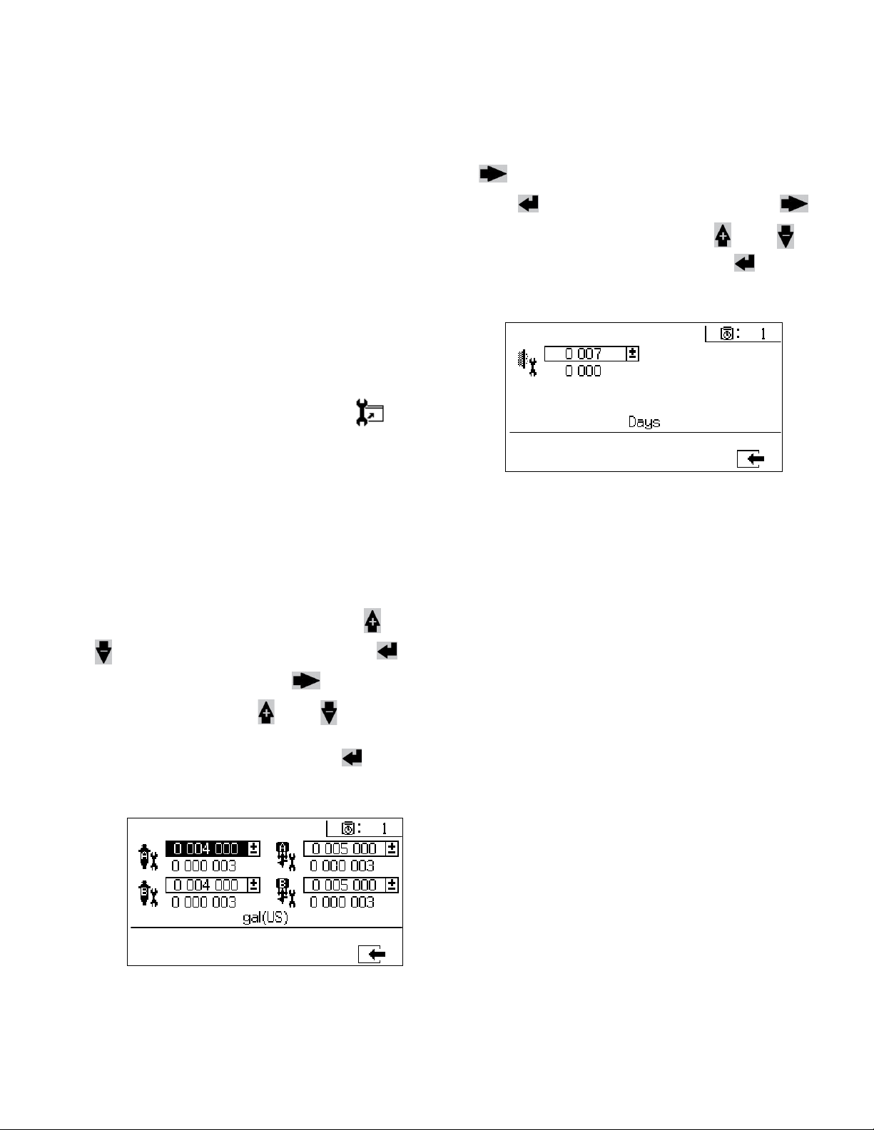
Set Maintenance Parameters (Optional)
NOTE:
Prior to configuring system settings, see Enable Setup
Screens, page 66, to ensure screens shown in this sec-
tion are viewable and configurable. If they are not, follow
instructions in Enable Setup Screens to enable them.
NOTE:
For details regarding the user interface display screens
see User Interface Display, page 61.
To set maintenance parameters for pumps and valves,
including maintenance schedules, press from
the Home Setup screen.
Use the first screen to set maintenance setpoint
amounts for pumps and dosing valves. Use the second
screen to set the maintenance schedule for changing
the incoming air filter.
Set Maintenance Schedule
To set the number of days between changing the incoming air filter that will result in a reminder advisory, press
to move to the Maintenance Setup 2 screen.
Press to make the field selectable. Press
to scroll through each digit, and press and to
scroll through the optional values. Press to save
the number of days value.
Set Maintenance Setpoints
To set maintenance setpoint values, press and
to move through each field, and press to
make a field selectable. Press to scroll through
each setpoint digit. Press and to scroll
through the optional values. Continue this process until
the desired setpoint is reached. Press to save
that setpoint.
312359J 25

Basic Operation
Set Sprayer Limits (Optional)
NOTE:
For details regarding the limits setup screens, see User
Limits Setup Screens, page 68.
To set and adjust pump pressure limits and temperature
limits:
1. Select in the Enable Setup 2 screen. See
Enable Setup Screens, page 66, for instructions.
2. From the Home Setup screen press to jump
to the limits screens.
3. Follow the instructions in Set Pressure Limits and
Set Temperature Limits.
Set Pressure Limits
Set Temperature Limits
Use the following instructions to set temperature limits
that if met will issue an advisory and/or warning.
Press to move to the temperature limits screen.
To set temperature limits, press and to move
through each field, and press to make a field
selectable. Press to scroll through each tempera-
ture digit, and press and to scroll through the
optional values. Continue this process until you reach
your desired temperature limit. Press to save the
value.
NOTE:
The allowable range for the temperature setpoint is 34° 160°F (1° - 71°C).
Use the following instructions to set pressure limits for
each pump that if met will issue an advisory and/or
warning.
To set pressure limits, press and to move
through each field, and press to make a field
selectable. Press to scroll through each pres-
sure digit, and press and to scroll through the
optional values. Continue this process until you reach
the desired pressure limit. Press to save.
NOTE:
The B pump pressure always runs 10-20% higher than
the A pump pressure.
26 312359J
Loading...